Embed Size (px)
Citation preview

Final Draft Version 3.0 September 30, 2004
GENERAL GUIDANCE AND SPECIFICATIONS
FOR AERONAUTICAL SURVEYS VOLUME B
AIRPORT IMAGERY ACQUISITION AND SUBMISSION TO THE NATIONAL GEODETIC SURVEY
FEDERAL AVIATION ADMINISTRATION

DRAFT
2
TABLE OF CONTENTS SUBJECT PAGE ______________________________________________________________________________ 1. GENERAL............................................................................................................. 3 2. DELIVERABLES.................................................................................................. 3 2.1 CONTRACTOR............................................................................................. 3 2.2 GOVERNMENT............................................................................................ 5 3. GROUND SURVEY IMAGE CONTROL POINTS…………………………… 6 3.1 IMAGE CONTROL POINTS……………………………………………… 6 3.2 IMAGE CONTROL POINT SKETCHES…………………………………. 6 3.3 ACCURACY AND DATUMS…………………………………………….. 6 3.4 SELECTION OF CONTROL POINTS……………………………………. 7 4. IMAGING EQUIPMENT AND MATERIALS.................................................... 7 4.1 CAMERA....................................................................................................... 7 4.2 FILM............................................................................................................... 7 5. FLYING HEIGHT................................................................................................. 8 6. WEATHER, SOLAR ALTITUDE, AND TIME OF YEAR................................. 8 6.1 CLOUDS........................................................................................................ 8 6.2 TREE LEAVES.............................................................................................. 8 6.3 WELL DEFINED IMAGES............................................................................ 8 6.4 VISIBILITY.................................................................................................... 8 6.5 SUN ANGLE.................................................................................................. 8 7. FLIGHT LINE NAVIGATION AND GUIDANCE............................................... 9
7.1 TILT................................................................................................................. 9 7.2 CRAB.............................................................................................................. 9 7.3 OVERLAP AND SIDELAP............................................................................. 9 8. IMAGE QUALITY................................................................................................ 9 9. POINTS OF CONTACT ...................................................................................... 9
DRAFT
3
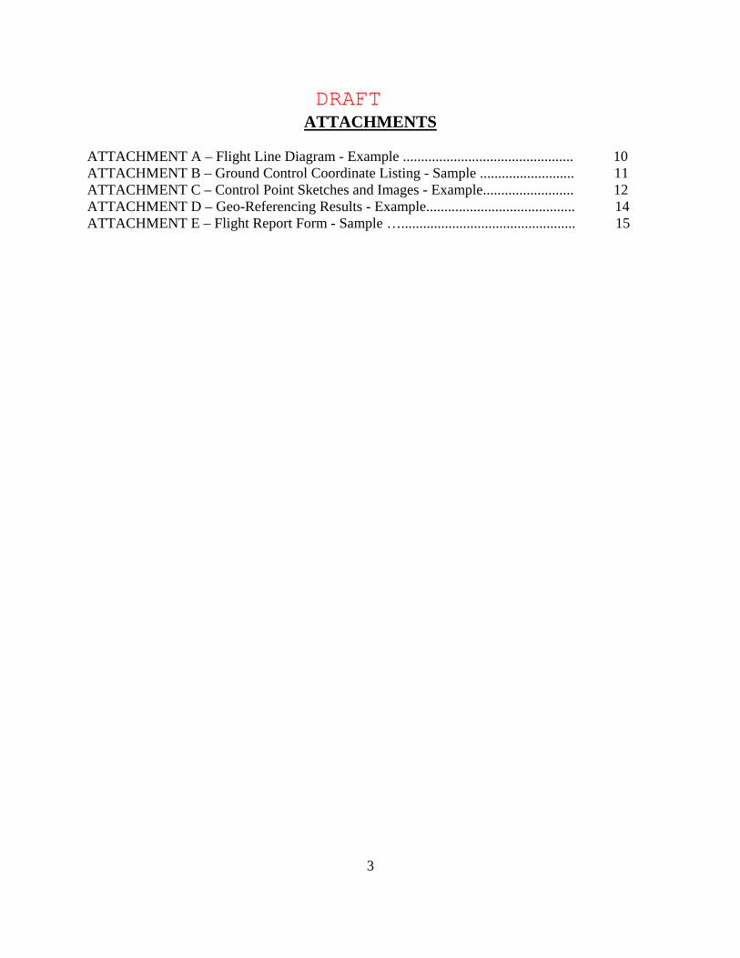
ATTACHMENTS ATTACHMENT A – Flight Line Diagram - Example ............................................... 10 ATTACHMENT B – Ground Control Coordinate Listing - Sample .......................... 11 ATTACHMENT C – Control Point Sketches and Images - Example......................... 12 ATTACHMENT D – Geo-Referencing Results - Example......................................... 14 ATTACHMENT E – Flight Report Form - Sample …................................................ 15
DRAFT
4
GENERAL GUIDANCE AND SPECIFICATIONS FOR AERONAUTICAL SURVEYS
VOLUME B AIRPORT IMAGERY ACQUISITION AND
SUBMISSION TO THE NATIONAL GEODETIC SURVEY
1. GENERAL These General Specifications provide guidance and specifications for contractors to acquire and submit airport imagery to The National Geodetic Survey (NGS) in support of airport surveys required by the Federal Aviation Administration’s (FAA) Airport Surveying-GIS Program. The FAA has tasked the Aeronautical Survey Program (ASP) at NGS to perform quality assurance on all airport surveys that are contracted by local airport authorities. The ASP is administered by NGS in accordance with an Interagency Agreement with the FAA. NGS will perform a photogrammetric analysis using this airport imagery to assure the survey data adheres to the most current editions of the appropriate FAA advisory circulars and documents. The following conventions have been adopted for this document. The term “shall” and “must” mean that compliance is required. The term “should” implies that compliance is not required, but is strongly recommended. All positional data provided under these specifications shall be referenced to the National Spatial Reference System (NSRS). The datum for the horizontal positions is the North American Datum of 1983 (NAD 83). The vertical datum is the North American Vertical Datum of 1988 (NAVD 88). Requests to exceed or deviate from this specification will be considered when written justification is provided to NGS in advance. No deviation is permitted until written approval is received from NGS. 2. DELIVERABLES 2.1 CONTRACTOR The contractor will provide to the Government (NGS ASP): A. Digital Stereo Imagery - The contractor shall provide NGS ASP with digital stereo imagery of the entire area to be analyzed. The dimensions of this area will depend on the type of survey that has been awarded to the contractor. Acquire the imagery within at least six (6) months prior to the ground survey. The digital imagery should be submitted well in advance to the ground survey and must be approved by NGS prior to the submission of ground survey data.
DRAFT
5
The imagery deliverables shall conform to the following requirements: - Delivery medium: - DVD or external USB compatible hard drive - Flight Line Diagram (see Attachment A) - File format - TIFF (Tagged Image File Format) or VITec Scanner Raster Format - Scanner (for imagery collected with film) - must use metric quality scanner - Pixel ground sample distance (GSD) 10-30 cm - Resolution - Must be of sufficient quality to allow photogrammetric measurement and
analysis of airport features - Image Quality - Shall meet the highest professional standards. Individual airport features shall
be readily discernable. B. Ground Control - The contractor shall provide NGS ASP with the following information: - Ground Control Survey Points File – An ASCII file listing the following: 1. Point ID/Station Name 2. Northing (UTM; meters, to 2 decimal places) 3. Easting (UTM; meters, to 2 decimal Places) 4. Orthometric Height (meters, to 2 decimal places; relative to NAVD 88) 5. Ellipsoid Height (meters, to 2 decimal places) (See Attachment B for coordinate file sample). - Ground Control Network Diagram - general diagram/sketch showing the
ground control network of control points. This may be incorporated with the Flight Line diagram (see Attachment A).
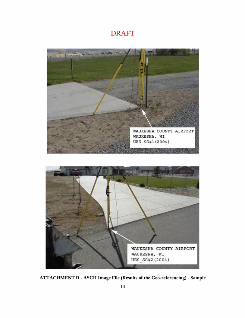
- Control Point Sketches/Images - Individual scanned sketches and digital
images of each ground control point (see Attachment C for sample). C. Geo-Referencing - The imagery provided shall be geo-referenced (such as by aero- triangulation, direct GPS/IMU observation, or both). For frame imagery, the contractor shall
provide an ASCII file that contains the focal length of the camera used and the X, Y, Z, omega, phi, kappa, of each image. The required coordinate system is the Universal Transverse Mercator (UTM) in NAD 83. Specify the UTM zone used. The submitted ASCII file must contain the following fields (See Attachment D for sample.):
1. Strip # 2. Image # 3. Easting (meters, to 2 decimal places) 4. Northing (meters, to 2 decimal places) 5. Orthometric Height (meters, to 2 decimal places) 6. Omega (in radians, to 7 decimal places) 7. Phi (in radians, to 7 decimal places) 8. Kappa (in radians, to 7 decimal places
DRAFT
6
D. Flight Report - The contractor shall submit an Imagery Flight Report to the NGS ASP. For a sample Flight Report see Attachment E. The contractor shall ensure all information contained on the sample Flight Report form is provided, if applicable. E. Camera Calibration Report - When an aerial film based camera system is used to acquire the imagery required for the survey, the contractor shall provide to NGS ASP the current USGS Camera Calibration certificate. This certificate shall be dated less than three (3) years from the time of imagery acquisition. If a digital camera is used, then the contractor shall provide NGS ASP with the calibration report and / or procedure for completing the equivalent as recommended by the manufacturer. F. Final Report - The contractor shall supply to NGS a Final Report including, at least, these sections:
1. Equipment used to perform this work, including hardware models and serial numbers, and software names and versions;
2. Flight planning, if performed; 3. Discussion of exposure settings used, filters used;
4. Ground Control Survey; 5. Geo-referencing procedures; 6. Aircraft navigation; 7. Weather, solar altitude, and time of year;
8. Any unusual circumstances or problems, including equipment malfunctions, (including those already reported);
9. Any deviations from these specifications (including those already reported); and 10. Any recommendations for changes in these specifications for future work.
G. Transmittal Letter - All submitted deliverables shall be accompanied with an appropriate Transmittal Letter. The Transmittal Letter shall contain an accurate listing of all enclosed items. 2.2 GOVERNMENT: The government (NGS ASP) will provide to the contractor: A. Receipt Acknowledgment - NGS ASP will acknowledge receipt of the imagery deliverables within two (2) working days. This acknowledgment, an e-mail from NGS ASP to the contractor, will also signify the start of the NGS ASP imagery acceptance review. B. Imagery Acceptance Review - NGS ASP will provide the contractor and FAA Surveying-GIS Program Manager with an Imagery Acceptance Report, via e-mail, within five (5) working days. If NGS ASP determines that the imagery is acceptable the contractor may then submit the airport ground survey data. If rejected the contractor shall re-submit new imagery as soon as possible for review. This is the primary reason for submitting the imagery well in advance of the airport ground survey portion. The imagery will be evaluated by the criteria listed below:
DRAFT
7
1. Ground Sample Distance - GSD between 10-30 cm 2. Stereo Coverage - Imagery has sufficient overlap to permit stereo coverage of
the entire area to be analyzed 3. Geometric Fidelity - Collection and processing of the image data will maintain, within accuracy requirements, the relationship between measurements made in the image model
and real world coordinates 4. Geo-Referencing - The imagery has been geo-referenced and the source data used for
completing the geo-referencing are provided (See Attachments B, C, and D) 5. Positional Accuracy- Positions of well defined points determined from the stereo imagery
shall be within 1 meter relative to the NSRS (NAD 83 NAVD 88) at the 95% confidence level for Easting, Northing, and orthometric height
6. Resolution - imagery must be sufficiently sharp to allow identification, analysis, and measurement of airport features and obstructions
7. Image Quality - The imagery shall be clear and evenly exposed across the format. The imagery shall be free from cloud, cloud shadows, smoke, haze, and any other
blemishes which interfere with the intended use of the imagery 8. Acquisition Date - The imagery should be acquired within the 6 month period prior the
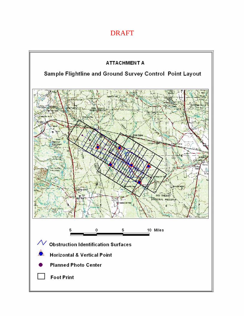
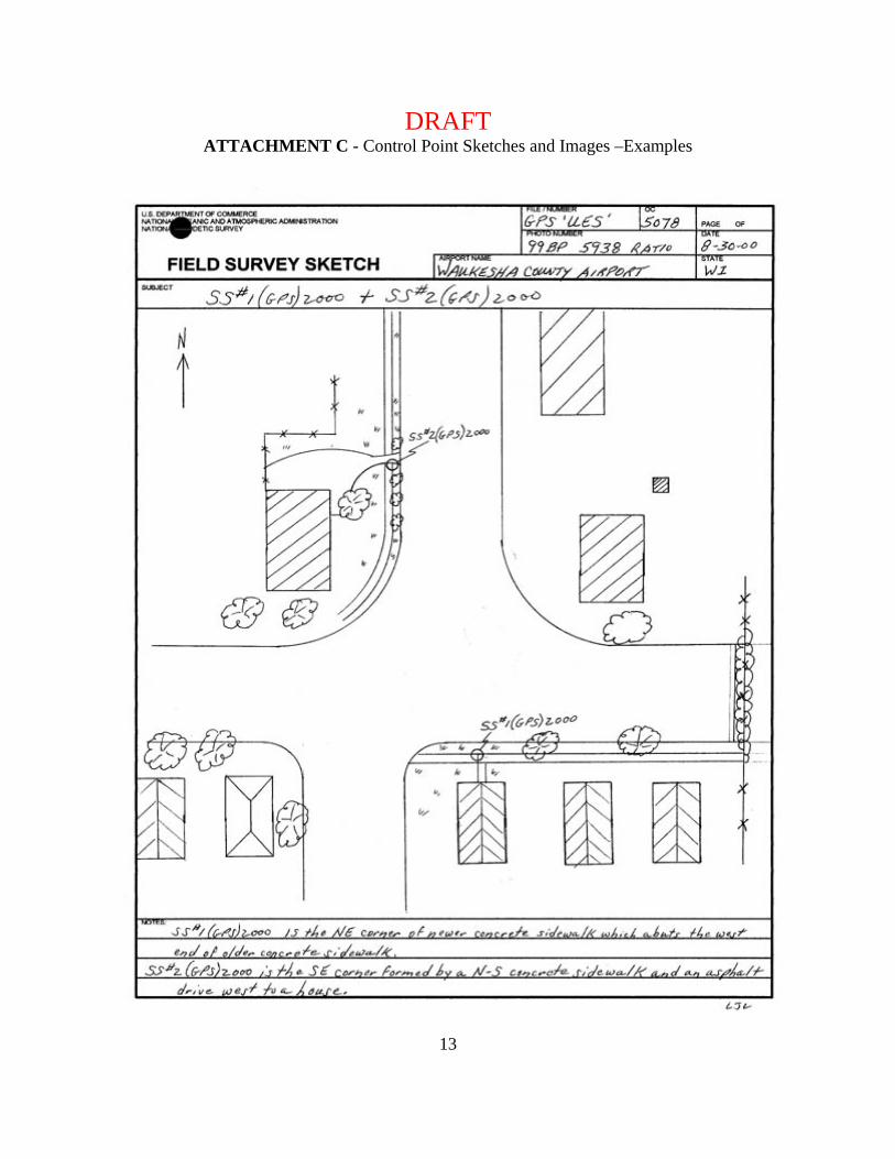
airport ground survey 9. Foliage – Imagery collected at time of full leaf foliage 3. GROUND SURVEY IMAGE CONTROL POINTS 3.1 IMAGE CONTROL POINTS - The contractor shall provide the ground surveyed control points used to geo-reference the imagery. A minimum of twenty (20) ground surveyed control points shall be provided at each airport. The control point locations shall be well defined, easily identifiable on the imagery, and well distributed throughout the area to be analyzed. 3.2 IMAGE CONTROL POINT SKETCHES - Two types of sketches are required. The first is a sketch of the entire airport area showing all control points (see Attachment A). Secondly, prepare a separate sketch of each control point, showing its immediate vicinity. See Attachment C “Field Survey Sketch,” for an example. Include a brief description of the point. 3.3 ACCURACY AND DATUMS
A. Horizontal positions shall be determined with an accuracy of 0.3 meters relative to the National Spatial Reference System (NSRS) NAD 83. B. Orthometric elevations shall be determined with an accuracy of 0.3 meters relative to the NSRS (NAVD 88). C. In Alaska and other areas outside the continental United States where NAVD 88 bench marks are not available, the Contractor shall make GPS ties to tidal bench marks or contact NGS for further guidance.
DRAFT
8
3.4 SELECTION OF CONTROL POINTS - The ideal type of point for control identification is one that produces a very small, recognizable, and symmetrical photographic image that has a distinct boundary of a relatively high to a lower contrast. Examples:
A. A point at well-defined junctions of intersecting features (sidewalks, abutments, and roads)
B. Corner points of any clear, well–defined feature (a parking lot, a tennis court, a road intersection)
C. The center of a small isolated bush. 4. EQUIPMENT AND MATERIAL GUIDANCE
4.1 CAMERA - The aerial camera used to collect imagery under these specifications and guidance shall be:
A. A Single lens film metric camera with quality equivalent to or better than a Wild RC 30
or Zeiss RMK-TOP, with Forward Motion Compensation;
OR B. Digital Aerial Sensors such as the Z/I DMC, Leica ADS 40, Emerge DDS, or
equivalent -The sensor shall be a geometrically stable and calibrated system suitable to use for
high-accuracy photogrammetric mapping;
-The sensor shall be of a high enough resolution and have a large enough Field of View (FOV) to meet the review requirements as listed in section 2.2.B.
-The sensor must record in the red, green, and blue (RGB) spectral bands and produce an image replicating natural color. If the sensor records in the near IR band, that shall also be provided.
4.2 FILM - If film is used to obtain images it shall be a high-resolution aerial film. Film emulsions shall be color negative (such as Kodak 2444 or Agfa X-100). The low contrast target resolution of the color negative emulsions shall be rated at greater than or equal to 80 lp/mm (line pairs per millimeter). Emulsion and filter combinations selected must be sensitive to and record on the film the green, yellow, orange, and red hues of the tree leaf canopy.
DRAFT
9
5. FLYING HEIGHT The target flying height shall be 12,000 feet above ground level (AGL) for film-based systems with a 6" focal length camera. The flying height shall not exceed 2% below or 5% above the target level. Flying height for a digital camera system shall be chosen to produce an image with resolution and quality greater than or equal to that obtained from a filmed based system as described above. 6. WEATHER, SOLAR ALTITUDE, AND TIME OF YEAR 6.1 CLOUDS - Clouds or cloud shadows shall NOT appear on the imagery. High, thin overcast will be permitted above the flying altitude if it does not cause ground mottling or a discernable reduction in light levels and/or ground object shadows. 6.2 TREE LEAVES - All imagery collected under these specifications and guidance shall show full tree leaf coverage to facilitate photogrammetric tree height determination. This requirement will limit the acquisition window depending on season and geographic location. 6.3 WELL DEFINED IMAGES - Imagery shall be collected only when well-defined images can be obtained. In addition to no clouds, imagery acquisition shall not be attempted where the ground is obscured by haze, smoke, smog, dust, or falling snow, sleet, rain, etc. Also, imagery acquisition shall not be conducted when the airport ground area is covered by water (flood), snow, or ice. 6.4 VISIBILITY - The minimum visibility at the time of exposure shall be 10 miles or greater. Visibility is determined by looking at objects on the ground toward the sun. The distance at which the detail of ground objects is clearly defined is the visibility. If the visibility is satisfactory, details of ground objects will be clearly defined at the edge of the view through the drift sight. 6.5 SUN ANGLE - Sun angle shall never be less than 30 degrees above the horizon at the time of imagery collection. Ideally, the sun angle should be between 40 and 60 degrees above the horizon because of the intermediate-size shadows produced. In mountainous areas with steep terrain and/or areas with tall trees, the minimum sun angle should be increased. Extreme shadowing may be cause for imagery rejection. Sun angle for a given day can be determined from a “Solar Altitude Diagram” or from appropriate computer software. See the U.S. Naval Observatory’s WWW site: http://aa.usno.navy.mil/data/docs/AltAz.html that computes sun altitudes and sun azimuths for U.S. locations and worldwide positions.
DRAFT
10
7. FLIGHT LINE NAVIGATION AND GUIDANCE All flight lines should be continuous. Flight lines should not be broken or patched. Note, a line re-flown shall have the original flight line number. See Attachment A for a flight line sample. 7.1 TILT - Care shall be taken to keep tilt (departure from the vertical) of the camera to a minimum. Tilt should not exceed +/- three (3) degrees. The average tilt for the entire project shall not exceed +/- one (1) degree. 7.2 CRAB - The imaging system shall be compensated for crab of the aircraft, with a resultant error not exceeding +/- five (5) degrees, as measured from the average line of flight, and the differential between any two successive exposures shall not exceed +/- five (5) degrees. 7.3 OVERLAP AND SIDELAP - For frame imaging systems, forward overlap shall average 60% between consecutive exposures. Forward overlap shall not be greater than 68% or less than 55% in any pair of consecutive images. Sidelap should be flight planned to minimize the collection of imagery outside of the area to be analyzed. This normally equates to 50% for a film-based system. The acceptable range for Sidelap shall be 30% to 60%. 8. IMAGE QUALITY Image quality shall meet the highest professional standards. Dark areas shall not bleed together and individual objects shall be readily discernable. Detail shall be sufficiently sharp to allow photogrammetric measurement of tree heights, compilation of runway/taxiway edges and other fine map features, and accomplishment of other intended uses for the imagery. Image products shall also be free of abrasions, blemishes, scratches, and irregularities. Fiducial marks shall be clearly visible and sharp on every image. 9. POINTS OF CONTACT: Image Review Coordinator Mgr. Aeronautical Survey Program National Geodetic Survey, NOAA National Geodetic Survey, NOAA ATTN: N/NGS33; SSMC3, Sta. 5359 ATTN: N/NGS, SSMC3, Sta. 8753 1315 East-West Highway 1315 East-West Highway Silver Spring, Maryland 20910 Silver Spring, Maryland 20910 301-713-2685 x-151 301-713-3198 x-100 FAX 301-713-4572 email: [email protected] email: [email protected]
DRAFT
11
DRAFT
12
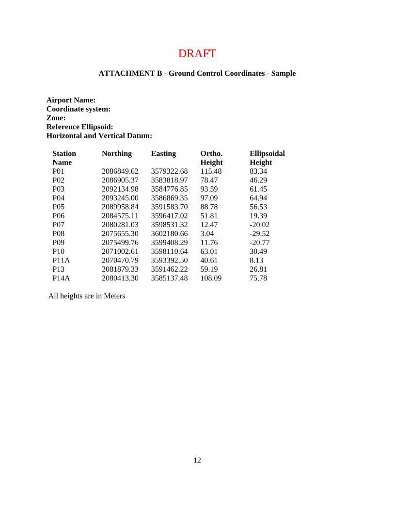
ATTACHMENT B - Ground Control Coordinates - Sample
Airport Name: Coordinate system: Zone: Reference Ellipsoid: Horizontal and Vertical Datum:
Station Name
Northing Easting Ortho. Height
Ellipsoidal Height
P01 2086849.62 3579322.68 115.48 83.34 P02 2086905.37 3583818.97 78.47 46.29 P03 2092134.98 3584776.85 93.59 61.45 P04 2093245.00 3586869.35 97.09 64.94 P05 2089958.84 3591583.70 88.78 56.53 P06 2084575.11 3596417.02 51.81 19.39 P07 2080281.03 3598531.32 12.47 -20.02 P08 2075655.30 3602180.66 3.04 -29.52 P09 2075499.76 3599408.29 11.76 -20.77 P10 2071002.61 3598110.64 63.01 30.49 P11A 2070470.79 3593392.50 40.61 8.13 P13 2081879.33 3591462.22 59.19 26.81 P14A 2080413.30 3585137.48 108.09 75.78
All heights are in Meters
DRAFT
13
ATTACHMENT C - Control Point Sketches and Images –Examples
DRAFT
14
ATTACHMENT D - ASCII Image File (Results of the Geo-referencing) - Sample
DRAFT
15
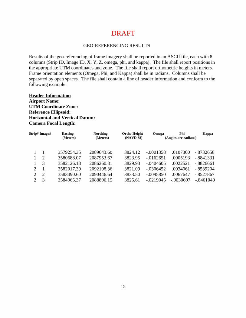
GEO-REFERENCING RESULTS Results of the geo-referencing of frame imagery shall be reported in an ASCII file, each with 8 columns (Strip ID, Image ID, X, Y, Z, omega, phi, and kappa). The file shall report positions in the appropriate UTM coordinates and zone. The file shall report orthometric heights in meters. Frame orientation elements (Omega, Phi, and Kappa) shall be in radians. Columns shall be separated by open spaces. The file shall contain a line of header information and conform to the following example: Header Information Airport Name: UTM Coordinate Zone: Reference Ellipsoid: Horizontal and Vertical Datum: Camera Focal Length: Strip# Image# Easting Northing Ortho Height Omega Phi Kappa (Meters) (Meters) (NAVD 88) (Angles are radians) 1 1 3579254.35 2089643.60 3824.12 -.0001358 .0107300 -.8732658 1 2 3580688.07 2087953.67 3823.95 -.0162651 .0005193 -.8841331 1 3 3582126.18 2086260.81 3829.93 -.0404605 .0022521 -.8826661 2 1 3582017.30 2092108.36 3821.09 -.0306452 .0034061 -.8539204 2 2 3583490.60 2090446.64 3833.50 -.0095850 .0067647 -.8527867 2 3 3584965.37 2088806.15 3825.61 -.0219045 -.0030697 -.8461040
DRAFT
16
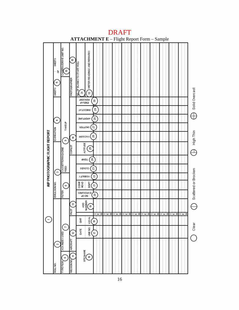
ATTACHMENT E – Flight Report Form – Sample
DRAFT
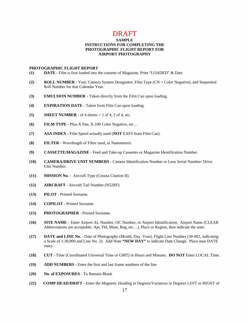
17
SAMPLE INSTRUCTIONS FOR COMPLETING THE PHOTOGRAPHIC FLIGHT REPORT FOR
AIRPORT PHOTOGRAPHY PHOTOGRAPHIC FLIGHT REPORT (1) DATE - Film is first loaded into the cassette of Magazine, Print “LOADED” & Date (2) ROLL NUMBER - Year, Camera System Designator, Film Type (CN = Color Negative), and Sequential
Roll Number for that Calendar Year. (3) EMULSION NUMBER – Taken directly from the Film Can upon loading. (4) EXPIRATION DATE - Taken from Film Can upon loading. (5) SHEET NUMBER - of 4 sheets = 1 of 4, 2 of 4, etc. (6) FILM TYPE - Plus-X Pan, X-100 Color Negative, etc… (7) ASA INDEX - Film Speed actually used (NOT EAFS from Film Can). (8) FILTER - Wavelength of Filter used, in Nanometers. (9) CASSETTE/MAGAZINE - Feed and Take-up Cassettes or Magazine Identification Number. (10) CAMERA/DRIVE UNIT NUMBERS - Camera Identification Number or Lens Serial Number/ Drive
Unit Number. (11) MISSION No. - Aircraft Type (Cessna Citation II). (12) AIRCRAFT - Aircraft Tail Number (N52RF) (13) PILOT - Printed Surname. (14) COPILOT - Printed Surname. (15) PHOTOGRAPHER - Printed Surname. (16) SITE NAME – Enter Airport AL Number, OC Number, or Airport Identification, Airport Name (CLEAR
Abbreviations are acceptable: Apt, Fld, Muni, Reg, etc…), Place or Region, then indicate the state. (17) DATE and LINE No. - Date of Photography (Month, Day, Year), Flight Line Number (30-002, indicating
a Scale of 1:30,000 and Line No. 2). Add Note “NEW DAY” to indicate Date Change. Place near DATE entry.
(18) CUT - Time (Coordinated Universal Time or GMT) in Hours and Minutes. DO NOT Enter LOCAL Time. (19) ADD NUMBERS - Enter the first and last frame numbers of the line (20) No. of EXPOSURES - To Remain Blank (21) COMP HEAD/DRIFT - Enter the Magnetic Heading in Degrees/Variances in Degrees LEFT or RIGHT of
DRAFT
18
the path of the Aircraft and Ground Tracking over the Planned Flight Line. (22) VISIBILITY - Distance in Statute Miles out from the Aircraft, in the Direction of the SUN, at which Tree
Crowns are still Separately Discernable. (23) CLOUDS - Enter an Estimate of Cloud-Cover from Choices at the Bottom of the Photographic Flight
Report. (24) TEMPERATURE - Enter the Temperature in Degrees Celsius at the Time of the Photography. (25) ALTITUDE - Feet Above Ground Level (AGL) over Airports. (26) VACUUM - Enter Vacuum Reading from Gauge or from Camera Display Panel (600 mmWs, or nominally
64 mb standard) (27) SHUTTER - Enter Speed of Shutter During Line of Photography. Enter, if in Automatic Mode, Variances
in Shutter Speeds (450-550). (28) APERTURE - Enter the Actual Aperture Used. Final Adjustment from Camera Indicator, NOT Base
Exposure from an Automatic Light meter. (29) RHEOSTAT - Enter the Rheostat Setting as a Function of the ASA (“PER xxx ASA”). (30) ENDLAP - Enter the Planned Endlap as a Whole Number (60, 80, etc.). (31) Number of Blanks to Start of Roll - “6" is Standard. (32) METER READINGS and REMARKS - Record the Automatic Light Meter Readings (4 @ 1000), a
Description of the Terrain, Local Ambient Conditions, and remarks concerning abnormalities.