Embed Size (px)
Citation preview
i
FINAL DRAINAGE REPORT for
7205 MAINE LANE Colorado Springs, Colorado
October 20, 2017
Prepared for:
Mountain Splendor Services
7205 Maine Lane Colorado Springs, CO 80923 Contact: Dan Combs
Prepared by:
Drexel, Barrell & Co. 3 South Seventh Street Colorado Springs, CO 80905 Contact: Tim McConnell, P.E. (719) 260-0887
ii
TABLE OF CONTENTS
1.0 CERTIFICATION STATEMENTS ............................................................................................ III 2.0 PURPOSE ............................................................................................................................. 1 3.0 GENERAL SITE DESCRIPTION .............................................................................................. 1 4.0 DRAINAGE CRITERIA .......................................................................................................... 2 5.0 EXISTING CONDITION ........................................................................................................ 2 6.0 EXISTING POLLUTANT SOURCES ........................................................................................ 3 7.0 SUMMARY ........................................................................................................................... 3 8.0 REFERENCES ....................................................................................................................... 3 APPENDICES VICINITY MAP SOILS MAP FLOODPLAIN MAP HYDROLOGY CALCULATIONS HYDRAULIC CALCULATIONS DRAINAGE MAP
iii
FINAL DRAINAGE REPORT for
7205 MAINE LANE Colorado Springs, Colorado
1.0 CERTIFICATION STATEMENTS ENGINEER'S STATEMENT The attached drainage plan and report were prepared under my direction and supervision and are correct to the best of my knowledge and belief. Said drainage report has been prepared according to the criteria established by El Paso County for drainage reports, and said report is in conformity with the master plan of the drainage basin. I accept responsibility for any liability caused by any negligent acts, errors or omission on my part in preparing this report. Tim D. McConnell, P.E. Date Colorado P.E. License No. 33797 For and on Behalf of Drexel, Barrell & Co. DEVELOPER'S STATEMENT I, the developer have read and will comply with all the requirements specified in this drainage report and plan. Business Name: Mountain Splendor Services By: Dan Combs Date Title: Owner Address: 7205 Maine Lane Colorado Springs, CO 80923 EL PASO COUNTY Filed in accordance with the requirements of the El Paso County Land Development Code, Drainage Criteria Manual Volumes 1 and 2, and the Engineering Criteria Manual, as amended. For the County Engineer Date CONDITIONS:
1
FINAL DRAINAGE REPORT for
7205 MAINE LANE Colorado Springs, Colorado
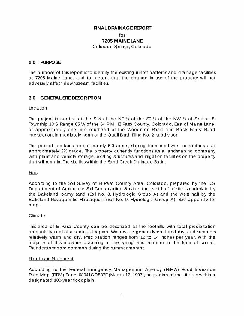
2.0 PURPOSE The purpose of this report is to identify the existing runoff patterns and drainage facilities at 7205 Maine Lane, and to present that the change in use of the property will not adversely affect downstream facilities.
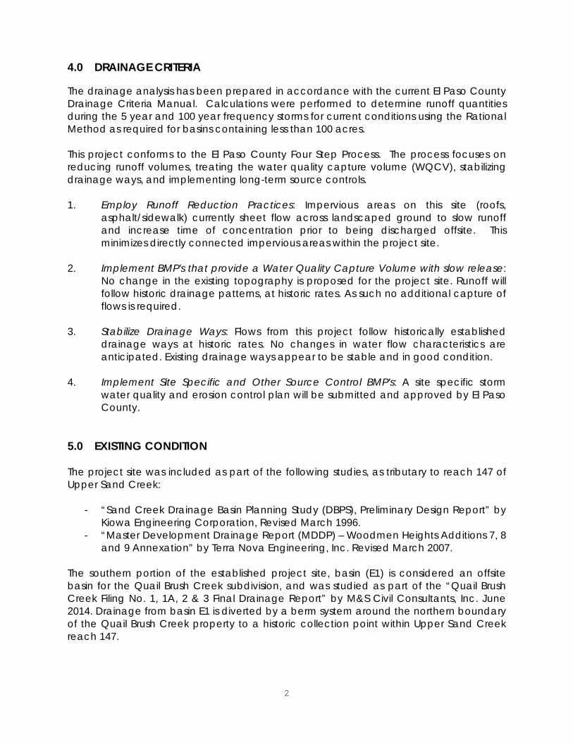
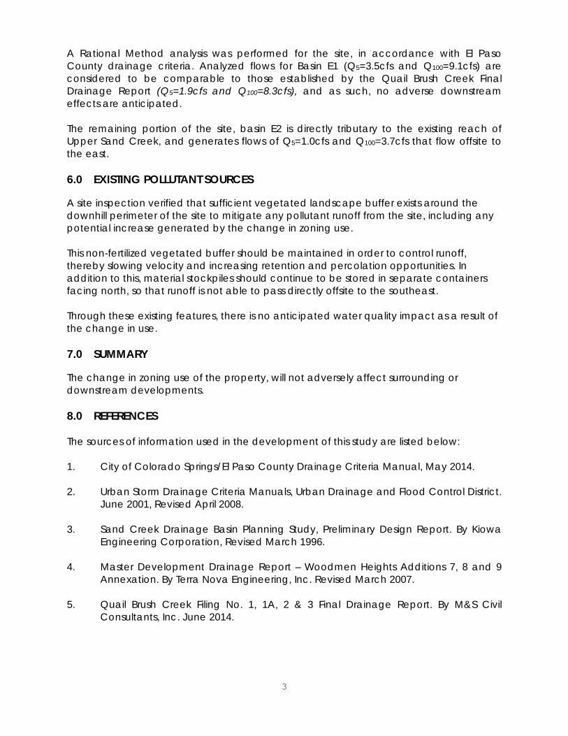
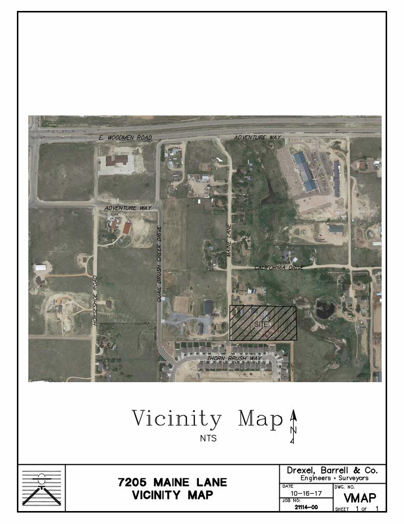
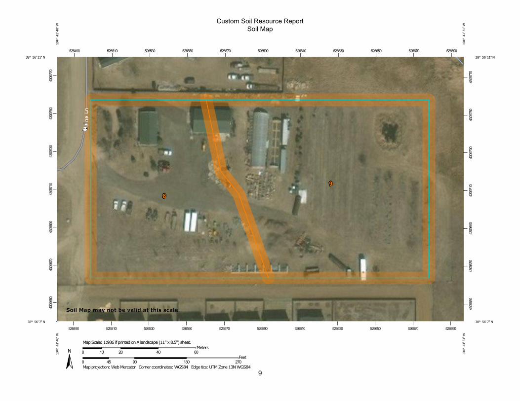
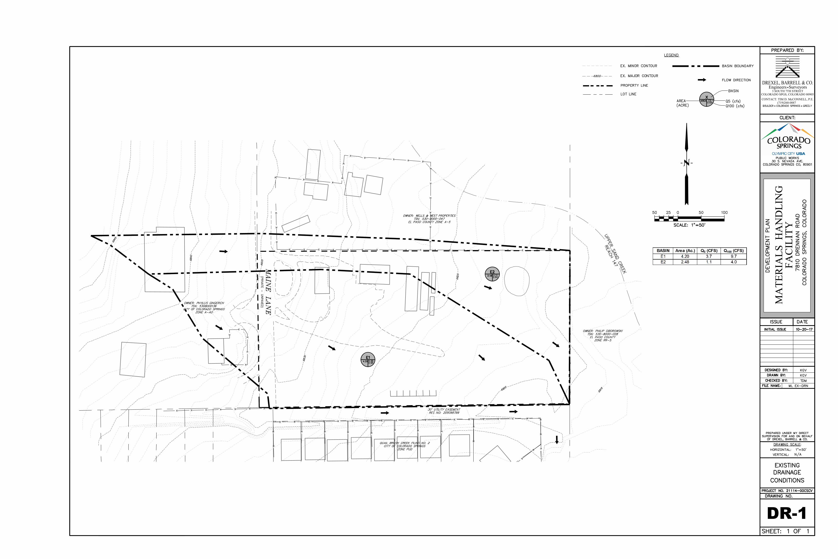
3.0 GENERAL SITE DESCRIPTION Location The project is located at the S ½ of the NE ¼ of the SE ¼ of the NW ¼ of Section 8, Township 13 S, Range 65 W of the 6th P.M., El Paso County, Colorado. East of Maine Lane, at approximately one mile southeast of the Woodmen Road and Black Forest Road intersection, immediately north of the Quail Brush Filing No. 2 subdivision The project contains approximately 5.0 acres, sloping from northwest to southeast at approximately 2% grade. The property currently functions as a landscaping company with plant and vehicle storage, existing structures and irrigation facilities on the property that will remain. The site lies within the Sand Creek Drainage Basin. Soils According to the Soil Survey of El Paso County Area, Colorado, prepared by the U.S. Department of Agriculture Soil Conservation Service, the east half of site is underlain by the Blakeland loamy sand (Soil No. 8, Hydrologic Group A) and the west half by the Blakeland-Fluvaquentic Haplaquolis (Soil No. 9, Hydrologic Group A). See appendix for map. Climate This area of El Paso County can be described as the foothills, with total precipitation amounts typical of a semi-arid region. Winters are generally cold and dry, and summers relatively warm and dry. Precipitation ranges from 12 to 14 inches per year, with the majority of this moisture occurring in the spring and summer in the form of rainfall. Thunderstorms are common during the summer months. Floodplain Statement According to the Federal Emergency Management Agency (FEMA) Flood Insurance Rate Map (FIRM) Panel 08041CO537F (March 17, 1997), no portion of the site lies within a designated 100-year floodplain.
2
4.0 DRAINAGE CRITERIA The drainage analysis has been prepared in accordance with the current El Paso County Drainage Criteria Manual. Calculations were performed to determine runoff quantities during the 5 year and 100 year frequency storms for current conditions using the Rational Method as required for basins containing less than 100 acres. This project conforms to the El Paso County Four Step Process. The process focuses on reducing runoff volumes, treating the water quality capture volume (WQCV), stabilizing drainage ways, and implementing long-term source controls. 1. Employ Runoff Reduction Practices: Impervious areas on this site (roofs,
asphalt/sidewalk) currently sheet flow across landscaped ground to slow runoff and increase time of concentration prior to being discharged offsite. This minimizes directly connected impervious areas within the project site.
2. Implement BMP's that provide a Water Quality Capture Volume with slow release:
No change in the existing topography is proposed for the project site. Runoff will follow historic drainage patterns, at historic rates. As such no additional capture of flows is required.
3. Stabilize Drainage Ways: Flows from this project follow historically established
drainage ways at historic rates. No changes in water flow characteristics are anticipated. Existing drainage ways appear to be stable and in good condition.
4. Implement Site Specific and Other Source Control BMP's: A site specific storm
water quality and erosion control plan will be submitted and approved by El Paso County.
5.0 EXISTING CONDITION The project site was included as part of the following studies, as tributary to reach 147 of Upper Sand Creek:
- “Sand Creek Drainage Basin Planning Study (DBPS), Preliminary Design Report” by Kiowa Engineering Corporation, Revised March 1996.
- “Master Development Drainage Report (MDDP) – Woodmen Heights Additions 7, 8 and 9 Annexation” by Terra Nova Engineering, Inc. Revised March 2007.
The southern portion of the established project site, basin (E1) is considered an offsite basin for the Quail Brush Creek subdivision, and was studied as part of the “Quail Brush Creek Filing No. 1, 1A, 2 & 3 Final Drainage Report” by M&S Civil Consultants, Inc. June 2014. Drainage from basin E1 is diverted by a berm system around the northern boundary of the Quail Brush Creek property to a historic collection point within Upper Sand Creek reach 147.
3
A Rational Method analysis was performed for the site, in accordance with El Paso County drainage criteria. Analyzed flows for Basin E1 (Q5=3.5cfs and Q100=9.1cfs) are considered to be comparable to those established by the Quail Brush Creek Final Drainage Report (Q5=1.9cfs and Q100=8.3cfs), and as such, no adverse downstream effects are anticipated. The remaining portion of the site, basin E2 is directly tributary to the existing reach of Upper Sand Creek, and generates flows of Q5=1.0cfs and Q100=3.7cfs that flow offsite to the east. 6.0 EXISTING POLLUTANT SOURCES A site inspection verified that sufficient vegetated landscape buffer exists around the downhill perimeter of the site to mitigate any pollutant runoff from the site, including any potential increase generated by the change in zoning use. This non-fertilized vegetated buffer should be maintained in order to control runoff, thereby slowing velocity and increasing retention and percolation opportunities. In addition to this, material stockpiles should continue to be stored in separate containers facing north, so that runoff is not able to pass directly offsite to the southeast. Through these existing features, there is no anticipated water quality impact as a result of the change in use. 7.0 SUMMARY The change in zoning use of the property, will not adversely affect surrounding or downstream developments. 8.0 REFERENCES The sources of information used in the development of this study are listed below: 1. City of Colorado Springs/El Paso County Drainage Criteria Manual, May 2014. 2. Urban Storm Drainage Criteria Manuals, Urban Drainage and Flood Control District. June 2001, Revised April 2008. 3. Sand Creek Drainage Basin Planning Study, Preliminary Design Report. By Kiowa
Engineering Corporation, Revised March 1996. 4. Master Development Drainage Report – Woodmen Heights Additions 7, 8 and 9
Annexation. By Terra Nova Engineering, Inc. Revised March 2007. 5. Quail Brush Creek Filing No. 1, 1A, 2 & 3 Final Drainage Report. By M&S Civil
Consultants, Inc. June 2014.

Vicinity Map

Soils Map
9
Custom Soil Resource ReportSoil Map
4309
650
4309
670
4309
690
4309
710
4309
730
4309
750
4309
770
4309
650
4309
670
4309
690
4309
710
4309
730
4309
750
4309
770
526490 526510 526530 526550 526570 526590 526610 526630 526650 526670 526690
526490 526510 526530 526550 526570 526590 526610 526630 526650 526670 526690
38° 56' 11'' N10
4° 4
1' 4
0'' W
38° 56' 11'' N
104°
41'
31'
' W
38° 56' 7'' N
104°
41'
40'
' W
38° 56' 7'' N
104°
41'
31'
' W
N
Map projection: Web Mercator Corner coordinates: WGS84 Edge tics: UTM Zone 13N WGS840 45 90 180 270
Feet0 10 20 40 60
MetersMap Scale: 1:986 if printed on A landscape (11" x 8.5") sheet.
Soil Map may not be valid at this scale.
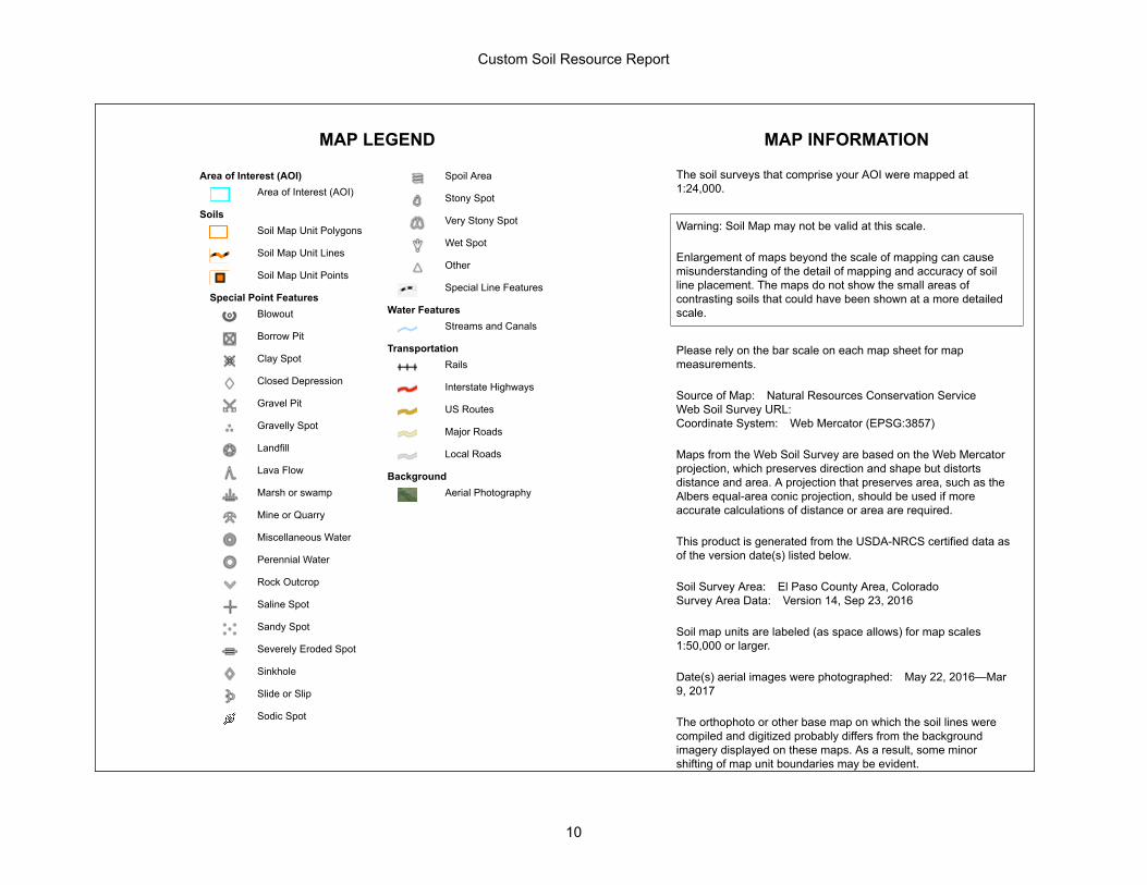
MAP LEGEND MAP INFORMATION
Area of Interest (AOI)Area of Interest (AOI)
SoilsSoil Map Unit Polygons
Soil Map Unit Lines
Soil Map Unit Points
Special Point FeaturesBlowout
Borrow Pit
Clay Spot
Closed Depression
Gravel Pit
Gravelly Spot
Landfill
Lava Flow
Marsh or swamp
Mine or Quarry
Miscellaneous Water
Perennial Water
Rock Outcrop
Saline Spot
Sandy Spot
Severely Eroded Spot
Sinkhole
Slide or Slip
Sodic Spot
Spoil Area
Stony Spot
Very Stony Spot
Wet Spot
Other
Special Line Features
Water FeaturesStreams and Canals
TransportationRails
Interstate Highways
US Routes
Major Roads
Local Roads
BackgroundAerial Photography
The soil surveys that comprise your AOI were mapped at1:24,000.
Warning: Soil Map may not be valid at this scale.
Enlargement of maps beyond the scale of mapping can causemisunderstanding of the detail of mapping and accuracy of soilline placement. The maps do not show the small areas ofcontrasting soils that could have been shown at a more detailedscale.
Please rely on the bar scale on each map sheet for mapmeasurements.
Source of Map: Natural Resources Conservation ServiceWeb Soil Survey URL:Coordinate System: Web Mercator (EPSG:3857)
Maps from the Web Soil Survey are based on the Web Mercatorprojection, which preserves direction and shape but distortsdistance and area. A projection that preserves area, such as theAlbers equal-area conic projection, should be used if moreaccurate calculations of distance or area are required.
This product is generated from the USDA-NRCS certified data asof the version date(s) listed below.
Soil Survey Area: El Paso County Area, ColoradoSurvey Area Data: Version 14, Sep 23, 2016
Soil map units are labeled (as space allows) for map scales1:50,000 or larger.
Date(s) aerial images were photographed: May 22, 2016—Mar9, 2017
The orthophoto or other base map on which the soil lines werecompiled and digitized probably differs from the backgroundimagery displayed on these maps. As a result, some minorshifting of map unit boundaries may be evident.
Custom Soil Resource Report
10
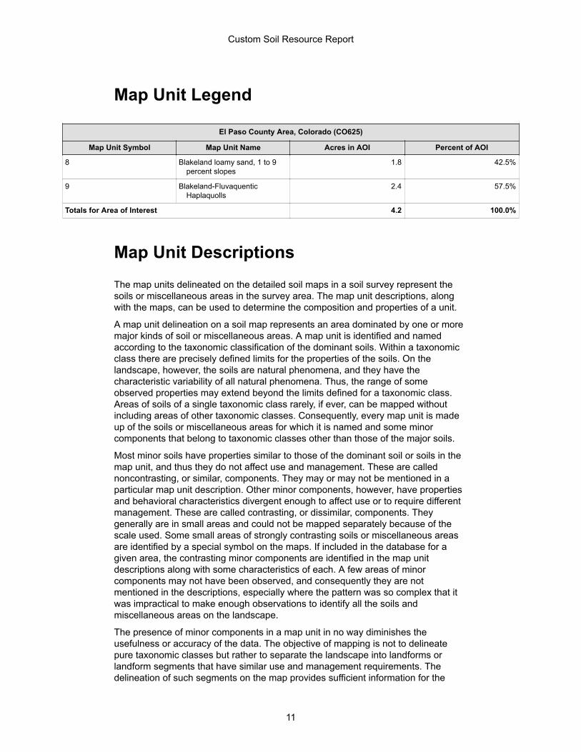
Map Unit Legend
El Paso County Area, Colorado (CO625)
Map Unit Symbol Map Unit Name Acres in AOI Percent of AOI
8 Blakeland loamy sand, 1 to 9percent slopes
1.8 42.5%
9 Blakeland-FluvaquenticHaplaquolls
2.4 57.5%
Totals for Area of Interest 4.2 100.0%
Map Unit DescriptionsThe map units delineated on the detailed soil maps in a soil survey represent thesoils or miscellaneous areas in the survey area. The map unit descriptions, alongwith the maps, can be used to determine the composition and properties of a unit.
A map unit delineation on a soil map represents an area dominated by one or moremajor kinds of soil or miscellaneous areas. A map unit is identified and namedaccording to the taxonomic classification of the dominant soils. Within a taxonomicclass there are precisely defined limits for the properties of the soils. On thelandscape, however, the soils are natural phenomena, and they have thecharacteristic variability of all natural phenomena. Thus, the range of someobserved properties may extend beyond the limits defined for a taxonomic class.Areas of soils of a single taxonomic class rarely, if ever, can be mapped withoutincluding areas of other taxonomic classes. Consequently, every map unit is madeup of the soils or miscellaneous areas for which it is named and some minorcomponents that belong to taxonomic classes other than those of the major soils.
Most minor soils have properties similar to those of the dominant soil or soils in themap unit, and thus they do not affect use and management. These are callednoncontrasting, or similar, components. They may or may not be mentioned in aparticular map unit description. Other minor components, however, have propertiesand behavioral characteristics divergent enough to affect use or to require differentmanagement. These are called contrasting, or dissimilar, components. Theygenerally are in small areas and could not be mapped separately because of thescale used. Some small areas of strongly contrasting soils or miscellaneous areasare identified by a special symbol on the maps. If included in the database for agiven area, the contrasting minor components are identified in the map unitdescriptions along with some characteristics of each. A few areas of minorcomponents may not have been observed, and consequently they are notmentioned in the descriptions, especially where the pattern was so complex that itwas impractical to make enough observations to identify all the soils andmiscellaneous areas on the landscape.
The presence of minor components in a map unit in no way diminishes theusefulness or accuracy of the data. The objective of mapping is not to delineatepure taxonomic classes but rather to separate the landscape into landforms orlandform segments that have similar use and management requirements. Thedelineation of such segments on the map provides sufficient information for the
Custom Soil Resource Report
11
development of resource plans. If intensive use of small areas is planned, however,onsite investigation is needed to define and locate the soils and miscellaneousareas.
An identifying symbol precedes the map unit name in the map unit descriptions.Each description includes general facts about the unit and gives important soilproperties and qualities.
Soils that have profiles that are almost alike make up a soil series. Except fordifferences in texture of the surface layer, all the soils of a series have majorhorizons that are similar in composition, thickness, and arrangement.
Soils of one series can differ in texture of the surface layer, slope, stoniness,salinity, degree of erosion, and other characteristics that affect their use. On thebasis of such differences, a soil series is divided into soil phases. Most of the areasshown on the detailed soil maps are phases of soil series. The name of a soil phasecommonly indicates a feature that affects use or management. For example, Alphasilt loam, 0 to 2 percent slopes, is a phase of the Alpha series.
Some map units are made up of two or more major soils or miscellaneous areas.These map units are complexes, associations, or undifferentiated groups.
A complex consists of two or more soils or miscellaneous areas in such an intricatepattern or in such small areas that they cannot be shown separately on the maps.The pattern and proportion of the soils or miscellaneous areas are somewhat similarin all areas. Alpha-Beta complex, 0 to 6 percent slopes, is an example.
An association is made up of two or more geographically associated soils ormiscellaneous areas that are shown as one unit on the maps. Because of presentor anticipated uses of the map units in the survey area, it was not consideredpractical or necessary to map the soils or miscellaneous areas separately. Thepattern and relative proportion of the soils or miscellaneous areas are somewhatsimilar. Alpha-Beta association, 0 to 2 percent slopes, is an example.
An undifferentiated group is made up of two or more soils or miscellaneous areasthat could be mapped individually but are mapped as one unit because similarinterpretations can be made for use and management. The pattern and proportionof the soils or miscellaneous areas in a mapped area are not uniform. An area canbe made up of only one of the major soils or miscellaneous areas, or it can be madeup of all of them. Alpha and Beta soils, 0 to 2 percent slopes, is an example.
Some surveys include miscellaneous areas. Such areas have little or no soilmaterial and support little or no vegetation. Rock outcrop is an example.
Custom Soil Resource Report
12
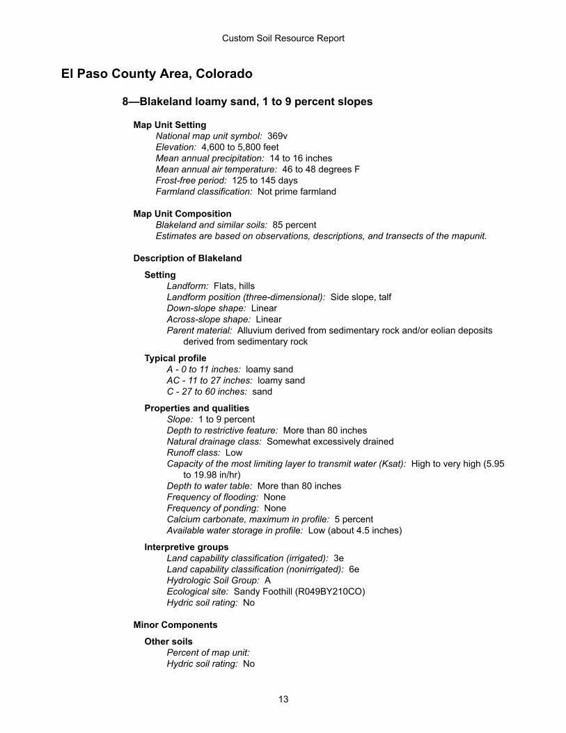
El Paso County Area, Colorado
8—Blakeland loamy sand, 1 to 9 percent slopes
Map Unit SettingNational map unit symbol: 369vElevation: 4,600 to 5,800 feetMean annual precipitation: 14 to 16 inchesMean annual air temperature: 46 to 48 degrees FFrost-free period: 125 to 145 daysFarmland classification: Not prime farmland
Map Unit CompositionBlakeland and similar soils: 85 percentEstimates are based on observations, descriptions, and transects of the mapunit.
Description of Blakeland
SettingLandform: Flats, hillsLandform position (three-dimensional): Side slope, talfDown-slope shape: LinearAcross-slope shape: LinearParent material: Alluvium derived from sedimentary rock and/or eolian deposits
derived from sedimentary rock
Typical profileA - 0 to 11 inches: loamy sandAC - 11 to 27 inches: loamy sandC - 27 to 60 inches: sand
Properties and qualitiesSlope: 1 to 9 percentDepth to restrictive feature: More than 80 inchesNatural drainage class: Somewhat excessively drainedRunoff class: LowCapacity of the most limiting layer to transmit water (Ksat): High to very high (5.95
to 19.98 in/hr)Depth to water table: More than 80 inchesFrequency of flooding: NoneFrequency of ponding: NoneCalcium carbonate, maximum in profile: 5 percentAvailable water storage in profile: Low (about 4.5 inches)
Interpretive groupsLand capability classification (irrigated): 3eLand capability classification (nonirrigated): 6eHydrologic Soil Group: AEcological site: Sandy Foothill (R049BY210CO)Hydric soil rating: No
Minor Components
Other soilsPercent of map unit: Hydric soil rating: No
Custom Soil Resource Report
13
PleasantPercent of map unit: Landform: DepressionsHydric soil rating: Yes
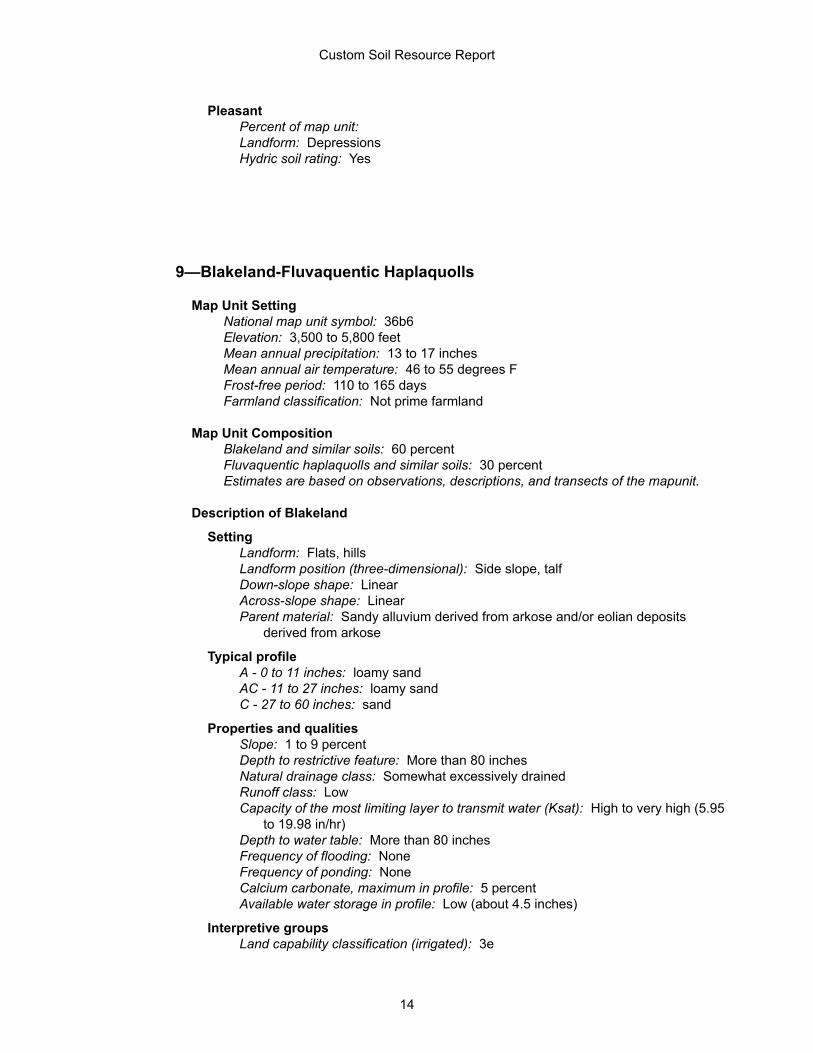
9—Blakeland-Fluvaquentic Haplaquolls
Map Unit SettingNational map unit symbol: 36b6Elevation: 3,500 to 5,800 feetMean annual precipitation: 13 to 17 inchesMean annual air temperature: 46 to 55 degrees FFrost-free period: 110 to 165 daysFarmland classification: Not prime farmland
Map Unit CompositionBlakeland and similar soils: 60 percentFluvaquentic haplaquolls and similar soils: 30 percentEstimates are based on observations, descriptions, and transects of the mapunit.
Description of Blakeland
SettingLandform: Flats, hillsLandform position (three-dimensional): Side slope, talfDown-slope shape: LinearAcross-slope shape: LinearParent material: Sandy alluvium derived from arkose and/or eolian deposits
derived from arkose
Typical profileA - 0 to 11 inches: loamy sandAC - 11 to 27 inches: loamy sandC - 27 to 60 inches: sand
Properties and qualitiesSlope: 1 to 9 percentDepth to restrictive feature: More than 80 inchesNatural drainage class: Somewhat excessively drainedRunoff class: LowCapacity of the most limiting layer to transmit water (Ksat): High to very high (5.95
to 19.98 in/hr)Depth to water table: More than 80 inchesFrequency of flooding: NoneFrequency of ponding: NoneCalcium carbonate, maximum in profile: 5 percentAvailable water storage in profile: Low (about 4.5 inches)
Interpretive groupsLand capability classification (irrigated): 3e
Custom Soil Resource Report
14
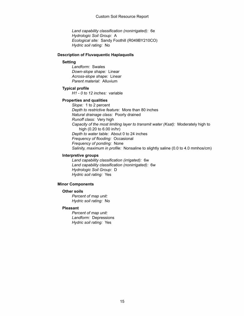
Land capability classification (nonirrigated): 6eHydrologic Soil Group: AEcological site: Sandy Foothill (R049BY210CO)Hydric soil rating: No
Description of Fluvaquentic Haplaquolls
SettingLandform: SwalesDown-slope shape: LinearAcross-slope shape: LinearParent material: Alluvium
Typical profileH1 - 0 to 12 inches: variable
Properties and qualitiesSlope: 1 to 2 percentDepth to restrictive feature: More than 80 inchesNatural drainage class: Poorly drainedRunoff class: Very highCapacity of the most limiting layer to transmit water (Ksat): Moderately high to
high (0.20 to 6.00 in/hr)Depth to water table: About 0 to 24 inchesFrequency of flooding: OccasionalFrequency of ponding: NoneSalinity, maximum in profile: Nonsaline to slightly saline (0.0 to 4.0 mmhos/cm)
Interpretive groupsLand capability classification (irrigated): 6wLand capability classification (nonirrigated): 6wHydrologic Soil Group: DHydric soil rating: Yes
Minor Components
Other soilsPercent of map unit: Hydric soil rating: No
PleasantPercent of map unit: Landform: DepressionsHydric soil rating: Yes
Custom Soil Resource Report
15

Floodplain Map
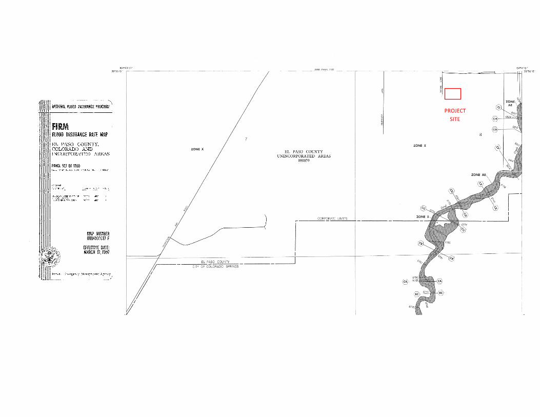
PROJECT SITE

Hydrology Calculations
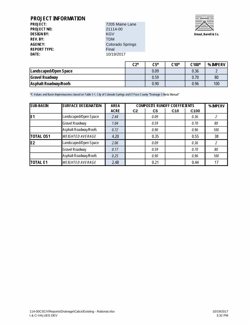
PROJECT INFORMATIONPROJECT:PROJECT NO:DESIGN BY:REV. BY:AGENCY:REPORT TYPE:
Drexel, Barrell & Co.
/ /
7205 Maine Lane21114-00KGVTDMColorado SpringsFinal
DATE:
C2* C5* C10* C100* % IMPERVLandscaped/Open Space 0.09 0.36 2Gravel Roadway 0.59 0.70 80Asphalt Roadway/Roofs 0.90 0.96 100
10/19/2017
*C-Values and Basin Imperviousness based on Table 5-1, City of Colorado Springs and El Paso County "Drainage Criteria Manual"
SUB-BASIN SURFACE DESIGNATION AREA % IMPERVACRE C2 C5 C10 C100
E1 2.44 0.09 0.36 2Gravel Roadway 1.04 0.59 0.70 80
0 72 0 90 0 96 100
COMPOSITE RUNOFF COEFFICIENTS
A h lt R d /R f
Landscaped/Open Space
0.72 0.90 0.96 100
TOTAL OS1 WEIGHTED AVERAGE 4.20 0.35 0.55 38E2 2.06 0.09 0.36 2
Gravel Roadway 0.17 0.59 0.70 800.25 0.90 0.96 100
TOTAL E1 WEIGHTED AVERAGE 2.48 0.21 0.44 17
Asphalt Roadway/Roofs
Landscaped/Open Space
Asphalt Roadway/Roofs
114-00CSCV\Reports\Drainage\Calcs\Existing - Rational.xlsxA & C-VALUES DEV
10/19/20173:32 PM
PROJECT INFORMATIONPROJECT: 7205 Maine LanePROJECT NO: 21114-00DESIGN BY: KGVREV. BY: TDMAGENCY: Colorado SpringsREPORT TYPE Fi l
Drexel, Barrell & Co.
REPORT TYPE: FinalDATE:
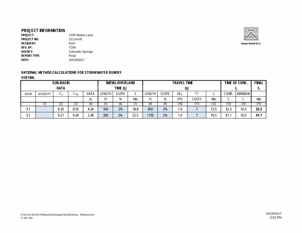
RATIONAL METHOD CALCULATIONS FOR STORM WATER RUNOFFEXISTING
SUB BASIN FINAL
10/19/2017
TIME OF CONC TRAVEL TIMEINITIAL/OVERLANDSUB-BASIN FINALDATA tc
BASIN DESIGN PT: C5 C100 AREA LENGTH SLOPE ti LENGTH SLOPE VEL. CV tt COMP. MINIMUMAc Ft % Min Ft % FPS COEFF Min tc t c Min
(1) (2) (3) (4) (5) (6) (7) (8) (9) (10) (11) (12) (13) (14) (15)
E1 0 35 0 55 4 20 300 2% 18 8 800 2% 1 0 7 13 5 32 3 10 0 32 3
tc
TIME OF CONC. TRAVEL TIME (tt)
INITIAL/OVERLANDTIME (ti)
E1 0.35 0.55 4.20 300 2% 18.8 800 2% 1.0 7 13.5 32.3 10.0 32.3E2 0.21 0.44 2.48 300 2% 22.5 1100 2% 1.0 7 18.5 41.1 10.0 41.1
H:\21114-00CSCV\Reports\Drainage\Calcs\Existing - Rational.xlsxTc dev site
10/19/20173:32 PM
PROJECT INFORMATIONPROJECT: 7205 Maine LanePROJECT NO: 21114-00DESIGN BY: KGVREV. BY: TDMAGENCY: Colorado Springs
Drexel, Barrell & Co.
p gREPORT TYPE: FinalDATE:
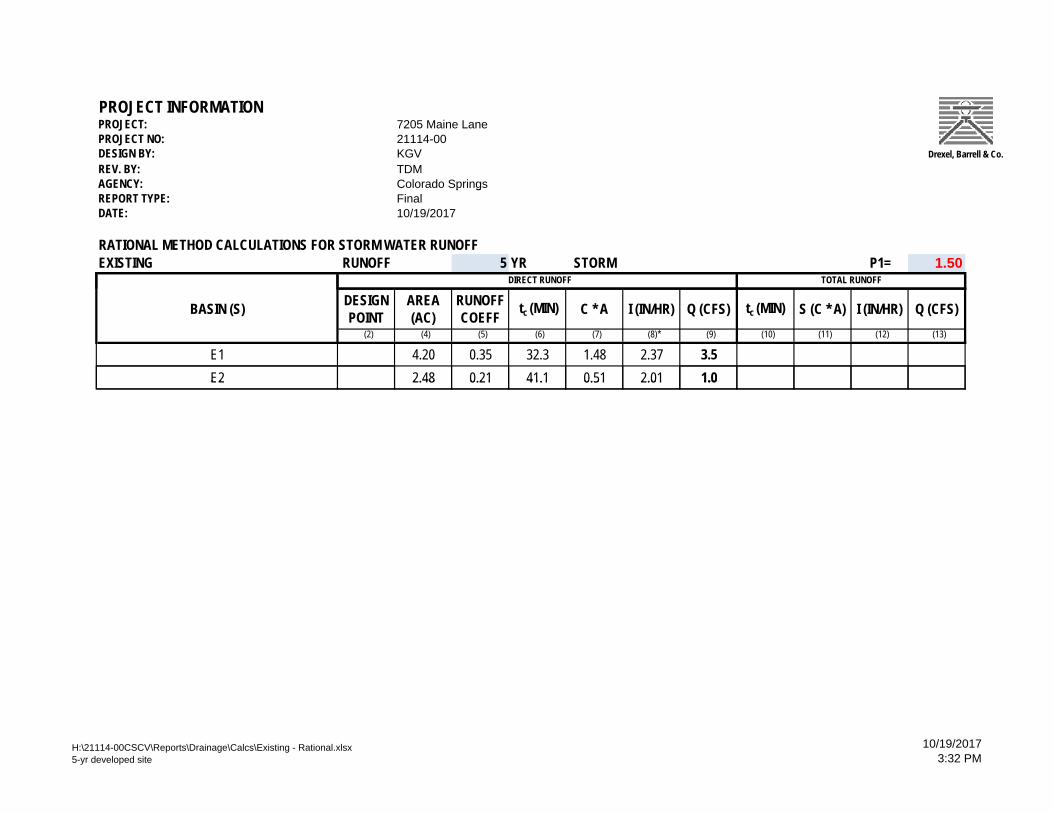
RATIONAL METHOD CALCULATIONS FOR STORM WATER RUNOFFEXISTING RUNOFF 5 YR STORM P1= 1.50
10/19/2017
TOTAL RUNOFF DIRECT RUNOFF
BASIN (S) DESIGN POINT
AREA (AC)
RUNOFF COEFF tc (MIN) C * A I (IN/HR) Q (CFS) tc (MIN) S (C * A) I (IN/HR) Q (CFS)
(2) (4) (5) (6) (7) (8)* (9) (10) (11) (12) (13)
E1 4.20 0.35 32.3 1.48 2.37 3.5E2 2.48 0.21 41.1 0.51 2.01 1.0E2 2.48 0.21 41.1 0.51 2.01 1.0
H:\21114-00CSCV\Reports\Drainage\Calcs\Existing - Rational.xlsx5-yr developed site
10/19/20173:32 PM
PROJECT INFORMATIONPROJECT: 7205 Maine LanePROJECT NO: 21114-00DESIGN BY: KGVREV. BY: TDMAGENCY: Colorado Springs
Drexel, Barrell & Co.
p gREPORT TYPE: FinalDATE:
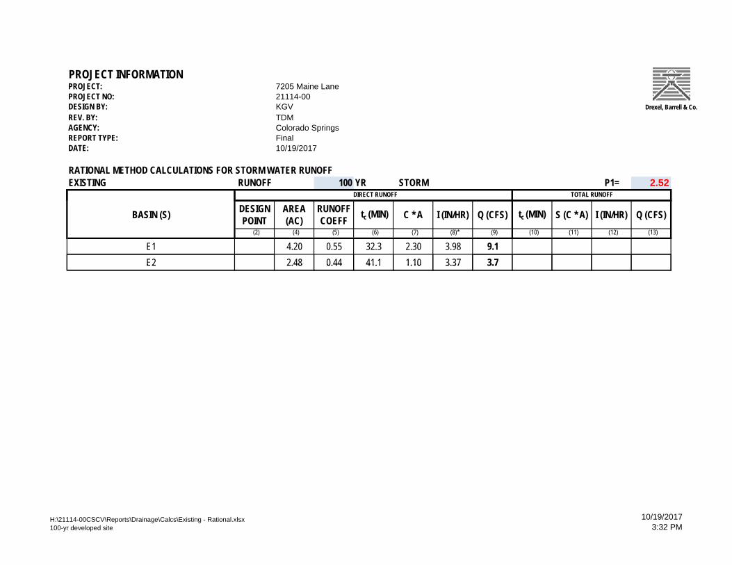
RATIONAL METHOD CALCULATIONS FOR STORM WATER RUNOFFEXISTING RUNOFF 100 YR STORM P1= 2.52
10/19/2017
TOTAL RUNOFF DIRECT RUNOFF
BASIN (S) DESIGN POINT
AREA (AC)
RUNOFF COEFF tc (MIN) C * A I (IN/HR) Q (CFS) tc (MIN) S (C * A) I (IN/HR) Q (CFS)
(2) (4) (5) (6) (7) (8)* (9) (10) (11) (12) (13)
E1 4.20 0.55 32.3 2.30 3.98 9.1E2 2.48 0.44 41.1 1.10 3.37 3.7E2 2.48 0.44 41.1 1.10 3.37 3.7
H:\21114-00CSCV\Reports\Drainage\Calcs\Existing - Rational.xlsx100-yr developed site
10/19/20173:32 PM

Drainage Map
DR-1
MA
TER
IALS
HA
ND
LIN
GFA
CIL
ITY
DREXEL, BARRELL & CO.Engineers Surveyors
3 SOUTH 7TH STREET COLORADO SPGS, COLORADO 80905CONTACT: TIM D. McCONNELL, P.E.
(719)260-0887