Embed Size (px)
Citation preview
ALASKA LNG PIPELINE Three-layer Polyethylene Coating
SPECIAL PERMIT: ATTACHMENT C DATE: AUGUST 1, 2019
Page 1 of 45
U.S. DEPARTMENT OF TRANSPORTATION
PIPELINE AND HAZARDOUS MATERIALS SAFETY ADMINISTRATION
Final Environmental Assessment
and
Finding of No Significant Impact
3LPE Coating Special Permit
Special Permit Information:
Docket Number: PHMSA-2017-0046
Requested By: Alaska Gasline Development Corporation
Operator ID#: 40015
Original Date Requested: April 14, 2017
Issuance Date: September 9, 2019
Effective Date: September 9, 2019
Code Section(s): 49 CFR 192.112(f)(1)
ALASKA LNG PIPELINE Three-layer Polyethylene Coating
SPECIAL PERMIT: ATTACHMENT C DATE: AUGUST 1, 2019
Page 2 of 45
Three-layer Polyethylene Coating - Special Permit
Final Environmental Assessment
This Final Environmental Assessment (FEA) analyzes the Alaska LNG Pipeline for a special permit
request from the Alaska Gasline Development Corporation (AGDC or Applicant) to waive the
requirements of 49 Code of Federal Regulations (CFR) 192.112(f)(1). The special permit request
described herein is related to, but distinct from, the Federal Energy Regulatory Commission (FERC)
decision making process for siting and permitting Alaska LNG’s Mainline pipeline to transport natural
gas to a facility on Alaska’s North Slope. The United States Department of Transportation’s (US DOT)
Pipeline and Hazardous Materials Safety Administration (PHMSA) does not have pipeline siting or
construction approval authority, but PHMSA’s Pipeline Safety Regulations impose certain safety
requirements that will apply to the Alaska LNG pipeline. The requirements for special permit
applications to PHMSA to request waiver from one or more safety regulations are described at
49 CFR 190.341. This FEA references the AGDC’s FERC Resource Reports to avoid duplication. The
FEA accompanies AGDC’s special permit request for the use of three-layer polyethylene (3LPE)
coating. This information can also be found in Appendix D, Environmental Information for Multi-Layer
Coating Special Permit of the Alaska LNG FERC Resource Report No. 11, Reliability and Safety found
on the FERC docket CP17-178, Accession Number 20170417-5342 which can be accessed through
https://elibrary.ferc.gov/IDMWS/common/OpenNat.asp?fileID=14562356.
I. Purpose and Need
AGDC is proposing to construct a 42-inch pipeline as part of an integrated liquefied natural gas
(LNG) project with interdependent facilities for the purpose of liquefying supplies of natural gas
from Alaska, in particular from the Point Thomson Unit (PTU) and Prudhoe Bay Unit (PBU)
production fields on the Alaska North Slope (North Slope), for export in foreign commerce and
for in-state deliveries of natural gas. The FERC is the lead federal agency. Pursuant to 49 USC
60101, et seq, and 49 CFR Part 192, PHMSA has authority over natural gas pipeline design,
construction, operation, and maintenance of natural gas pipelines to maintain safety. As noted
above, PHMSA does not have pipeline siting authority or construction approval authority.
Special permits can be granted under 49 CFR 190.341 for deviations from the regulatory
requirements. PHMSA imposes conditions on the grant of special permits to assure safety and
ALASKA LNG PIPELINE Three-layer Polyethylene Coating
SPECIAL PERMIT: ATTACHMENT C DATE: AUGUST 1, 2019
Page 3 of 45
environmental protection in accordance with 49 CFR 190.341. PHMSA complies with the
National Environmental Policy Act (NEPA) in deciding whether to issue the special permit.
The AGDC special permit will allow exemption from the requirements of 49 CFR 192.112(f)(1)
in pipeline segments that are built to comply with the alternative maximum allowable operation
pressure (MAOP) requirements of 49 CFR 192. This clause requires that “The pipe must be
protected against external corrosion by a non-shielding coating.”
The Alaska LNG Pipeline1 will traverse the state of Alaska. Construction will require transport of
line pipe significant distances to remote regions. Fusion bonded epoxy (FBE) coatings, which are
in common use in the contiguous U.S. (Lower 48), are susceptible to damage during
transportation and installation. As a result, the AGDC plans to utilize 3LPE coatings, which
consist of an FBE layer, a copolymer adhesive layer, and a polyethylene outer layer. 3LPE
coatings have increased resistance to damage during transportation and installation. A special
permit allows the application of 3LPE coatings to reduce the number of coating repairs, and
install a pipeline with fewer coating holidays and higher integrity. The special permit includes
conditions to ensure the pipeline has equal or greater safety than a pipeline constructed in
accordance with 49 CFR Part 192.
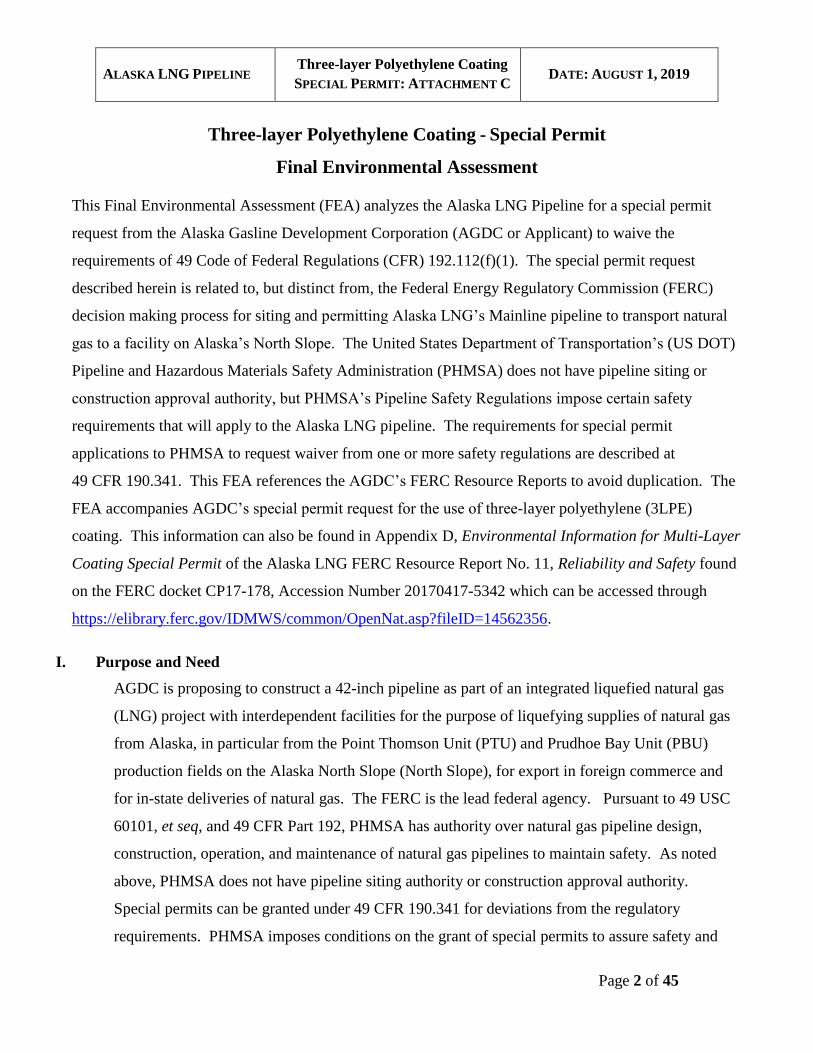
II. Background and Site Description
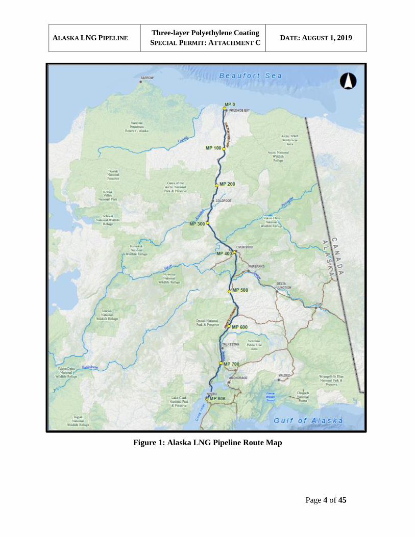
The Alaska LNG Pipeline route from the proposed gas treatment plant (GTP) located at Prudhoe
Bay to the LNG Plant site located on the Kenai Peninsula is shown in Figure 1. The Alaska LNG
Pipeline will be a 42-inch-diameter natural gas pipeline, approximately 807 miles in length,
extending from the GTP on the North Slope to the Liquefaction Facility on the shore of Cook
Inlet near Nikiski, including an offshore pipeline section crossing Cook Inlet. The onshore
pipeline will be a buried pipeline except for short, aboveground special design segments, such as
aerial water crossings and aboveground fault crossings.
ALASKA LNG PIPELINE Three-layer Polyethylene Coating
SPECIAL PERMIT: ATTACHMENT C DATE: AUGUST 1, 2019
Page 4 of 45
Figure 1: Alaska LNG Pipeline Route Map
ALASKA LNG PIPELINE Three-layer Polyethylene Coating
SPECIAL PERMIT: ATTACHMENT C DATE: AUGUST 1, 2019
Page 5 of 45
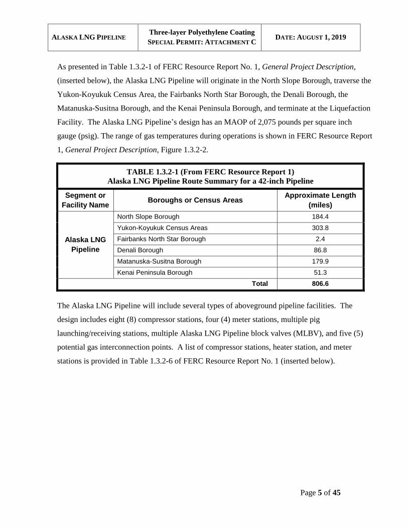
As presented in Table 1.3.2-1 of FERC Resource Report No. 1, General Project Description,
(inserted below), the Alaska LNG Pipeline will originate in the North Slope Borough, traverse the
Yukon-Koyukuk Census Area, the Fairbanks North Star Borough, the Denali Borough, the
Matanuska-Susitna Borough, and the Kenai Peninsula Borough, and terminate at the Liquefaction
Facility. The Alaska LNG Pipeline’s design has an MAOP of 2,075 pounds per square inch
gauge (psig). The range of gas temperatures during operations is shown in FERC Resource Report
1, General Project Description, Figure 1.3.2-2.
TABLE 1.3.2-1 (From FERC Resource Report 1)
Alaska LNG Pipeline Route Summary for a 42-inch Pipeline
Segment or
Facility Name Boroughs or Census Areas
Approximate Length
(miles)
Alaska LNG
Pipeline
North Slope Borough 184.4
Yukon-Koyukuk Census Areas 303.8
Fairbanks North Star Borough 2.4
Denali Borough 86.8
Matanuska-Susitna Borough 179.9
Kenai Peninsula Borough 51.3
Total 806.6
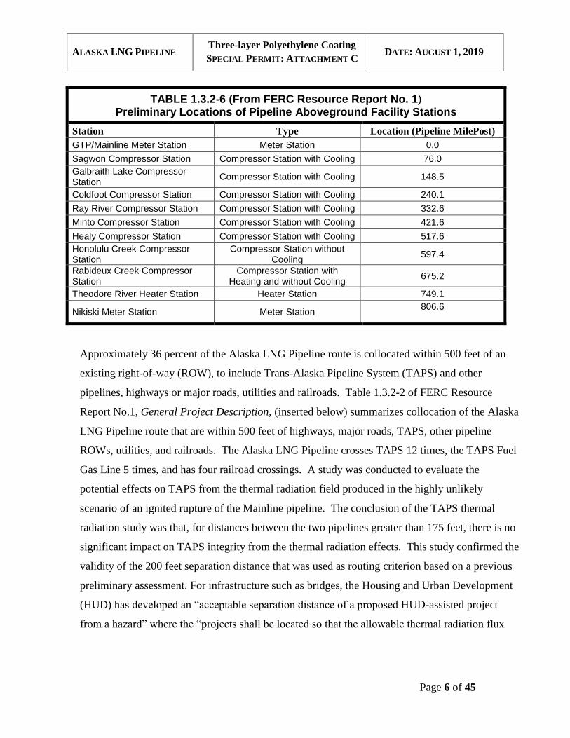
The Alaska LNG Pipeline will include several types of aboveground pipeline facilities. The
design includes eight (8) compressor stations, four (4) meter stations, multiple pig
launching/receiving stations, multiple Alaska LNG Pipeline block valves (MLBV), and five (5)
potential gas interconnection points. A list of compressor stations, heater station, and meter
stations is provided in Table 1.3.2-6 of FERC Resource Report No. 1 (inserted below).
ALASKA LNG PIPELINE Three-layer Polyethylene Coating
SPECIAL PERMIT: ATTACHMENT C DATE: AUGUST 1, 2019
Page 6 of 45
TABLE 1.3.2-6 (From FERC Resource Report No. 1) Preliminary Locations of Pipeline Aboveground Facility Stations
Station Type Location (Pipeline MilePost)
GTP/Mainline Meter Station Meter Station 0.0
Sagwon Compressor Station Compressor Station with Cooling 76.0
Galbraith Lake Compressor Station
Compressor Station with Cooling 148.5
Coldfoot Compressor Station Compressor Station with Cooling 240.1
Ray River Compressor Station Compressor Station with Cooling 332.6
Minto Compressor Station Compressor Station with Cooling 421.6
Healy Compressor Station Compressor Station with Cooling 517.6
Honolulu Creek Compressor Station
Compressor Station without Cooling
597.4
Rabideux Creek Compressor Station
Compressor Station with Heating and without Cooling
675.2
Theodore River Heater Station Heater Station 749.1
Nikiski Meter Station Meter Station 806.6
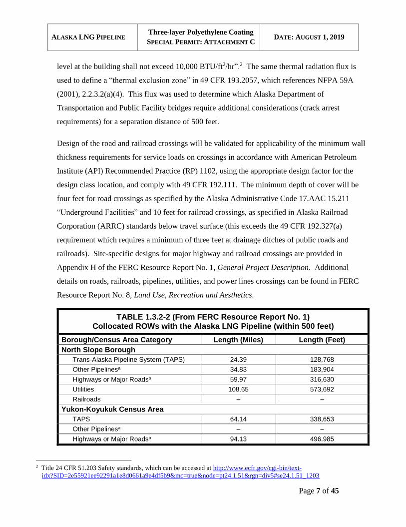
Approximately 36 percent of the Alaska LNG Pipeline route is collocated within 500 feet of an
existing right-of-way (ROW), to include Trans-Alaska Pipeline System (TAPS) and other
pipelines, highways or major roads, utilities and railroads. Table 1.3.2-2 of FERC Resource
Report No.1, General Project Description, (inserted below) summarizes collocation of the Alaska
LNG Pipeline route that are within 500 feet of highways, major roads, TAPS, other pipeline
ROWs, utilities, and railroads. The Alaska LNG Pipeline crosses TAPS 12 times, the TAPS Fuel
Gas Line 5 times, and has four railroad crossings. A study was conducted to evaluate the
potential effects on TAPS from the thermal radiation field produced in the highly unlikely
scenario of an ignited rupture of the Mainline pipeline. The conclusion of the TAPS thermal
radiation study was that, for distances between the two pipelines greater than 175 feet, there is no
significant impact on TAPS integrity from the thermal radiation effects. This study confirmed the
validity of the 200 feet separation distance that was used as routing criterion based on a previous
preliminary assessment. For infrastructure such as bridges, the Housing and Urban Development
(HUD) has developed an “acceptable separation distance of a proposed HUD-assisted project
from a hazard” where the “projects shall be located so that the allowable thermal radiation flux
ALASKA LNG PIPELINE Three-layer Polyethylene Coating
SPECIAL PERMIT: ATTACHMENT C DATE: AUGUST 1, 2019
Page 7 of 45
level at the building shall not exceed 10,000 BTU/ft2/hr”.2 The same thermal radiation flux is
used to define a “thermal exclusion zone” in 49 CFR 193.2057, which references NFPA 59A
(2001), 2.2.3.2(a)(4). This flux was used to determine which Alaska Department of
Transportation and Public Facility bridges require additional considerations (crack arrest
requirements) for a separation distance of 500 feet.
Design of the road and railroad crossings will be validated for applicability of the minimum wall
thickness requirements for service loads on crossings in accordance with American Petroleum
Institute (API) Recommended Practice (RP) 1102, using the appropriate design factor for the
design class location, and comply with 49 CFR 192.111. The minimum depth of cover will be
four feet for road crossings as specified by the Alaska Administrative Code 17.AAC 15.211
“Underground Facilities” and 10 feet for railroad crossings, as specified in Alaska Railroad
Corporation (ARRC) standards below travel surface (this exceeds the 49 CFR 192.327(a)
requirement which requires a minimum of three feet at drainage ditches of public roads and
railroads). Site-specific designs for major highway and railroad crossings are provided in
Appendix H of the FERC Resource Report No. 1, General Project Description. Additional
details on roads, railroads, pipelines, utilities, and power lines crossings can be found in FERC
Resource Report No. 8, Land Use, Recreation and Aesthetics.
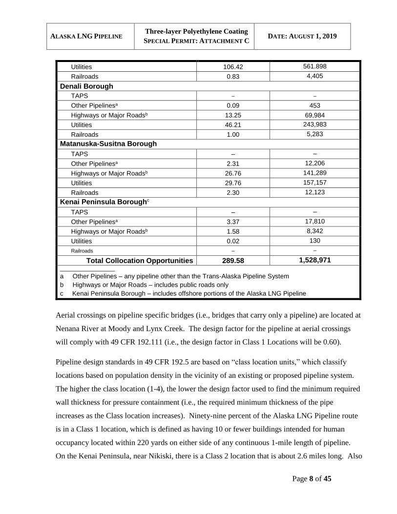
TABLE 1.3.2-2 (From FERC Resource Report No. 1) Collocated ROWs with the Alaska LNG Pipeline (within 500 feet)
Borough/Census Area Category Length (Miles) Length (Feet)
North Slope Borough
Trans-Alaska Pipeline System (TAPS) 24.39 128,768
Other Pipelinesa 34.83 183,904
Highways or Major Roadsb 59.97 316,630
Utilities 108.65 573,692
Railroads – –
Yukon-Koyukuk Census Area
TAPS 64.14 338,653
Other Pipelinesa – –
Highways or Major Roadsb 94.13 496.985
2 Title 24 CFR 51.203 Safety standards, which can be accessed at http://www.ecfr.gov/cgi-bin/text-
idx?SID=2e55921ee92291a1e8d0661a9e4df5b9&mc=true&node=pt24.1.51&rgn=div5#se24.1.51_1203
ALASKA LNG PIPELINE Three-layer Polyethylene Coating
SPECIAL PERMIT: ATTACHMENT C DATE: AUGUST 1, 2019
Page 8 of 45
Utilities 106.42 561.898
Railroads 0.83 4,405
Denali Borough
TAPS – –
Other Pipelinesa 0.09 453
Highways or Major Roadsb 13.25 69,984
Utilities 46.21 243,983
Railroads 1.00 5,283
Matanuska-Susitna Borough
TAPS – –
Other Pipelinesa 2.31 12,206
Highways or Major Roadsb 26.76 141,289
Utilities 29.76 157,157
Railroads 2.30 12,123
Kenai Peninsula Boroughc
TAPS – –
Other Pipelinesa 3.37 17,810
Highways or Major Roadsb 1.58 8,342
Utilities 0.02 130
Railroads – –
Total Collocation Opportunities 289.58 1,528,971 ___________________
a Other Pipelines – any pipeline other than the Trans-Alaska Pipeline System
b Highways or Major Roads – includes public roads only
c Kenai Peninsula Borough – includes offshore portions of the Alaska LNG Pipeline
Aerial crossings on pipeline specific bridges (i.e., bridges that carry only a pipeline) are located at
Nenana River at Moody and Lynx Creek. The design factor for the pipeline at aerial crossings
will comply with 49 CFR 192.111 (i.e., the design factor in Class 1 Locations will be 0.60).
Pipeline design standards in 49 CFR 192.5 are based on “class location units,” which classify
locations based on population density in the vicinity of an existing or proposed pipeline system.
The higher the class location (1-4), the lower the design factor used to find the minimum required
wall thickness for pressure containment (i.e., the required minimum thickness of the pipe
increases as the Class location increases). Ninety-nine percent of the Alaska LNG Pipeline route
is in a Class 1 location, which is defined as having 10 or fewer buildings intended for human
occupancy located within 220 yards on either side of any continuous 1-mile length of pipeline.
On the Kenai Peninsula, near Nikiski, there is a Class 2 location that is about 2.6 miles long. Also

ALASKA LNG PIPELINE Three-layer Polyethylene Coating
SPECIAL PERMIT: ATTACHMENT C DATE: AUGUST 1, 2019
Page 9 of 45
on the Kenai Peninsula there is a potential Class 3 location as the Alaska LNG Pipeline nears the
LNG Plant. In the Nenana Canyon region of Denali National Park (~milepost [MP] 536) there is
approximately a 0.5-mile of Class 3 location. Additional details on class locations for the Alaska
LNG Pipeline can be found in FERC Resource Report No. 11, Reliability and Safety, Section
11.7. Resource Report No. 11 Table 11.7.2-1 that outlines Class Locations for the Mainline of
Alaska LNG, Route Revision C2, is reproduced below.
TABLE 11.7.2-1 (From FERC Resource Report No. 11)
Class Locations for the Alaska LNG Pipeline
Milepost (MP)
Class Location
Start
(MP)
End
(MP)
0.00 535.99 1
535.99 536.49 3
536.49 798.65 1
798.65 801.27 2
801.27 803.78 1
803.78 806.25 2
806.25 806.57 1
There are 10 potential high consequence areas (HCA) along the Alaska LNG Pipeline as defined
under 49 CFR 192.903. Details of HCA locations can be found in FERC Resource Report No.
11, Section 11.7.
In addition, the pipeline route segments addressed in the special permit for Strain Based Design
([SBD] segments) will be incorporated into the integrity management program (IMP) and treated
as covered segments in HCA in accordance with 49 CFR Part 192, Subpart O, and the associated
special permit conditions if the special permit for Strain Based Design is granted by PHMSA.
The construction ROW width will vary depending on the type of terrain, the season of
construction, and the ease of access from nearby roads. The permanent ROW width will be 50
feet plus the diameter of the pipeline (i.e., 53.5 feet). Greater details on construction ROW can be
found in FERC Resource Report No. 1, General Project Description. The Alaska LNG Pipeline
will be sited on land composed of more than 85 percent federal, State of Alaska, and borough land
ALASKA LNG PIPELINE Three-layer Polyethylene Coating
SPECIAL PERMIT: ATTACHMENT C DATE: AUGUST 1, 2019
Page 10 of 45
of various holdings, with the remainder on privately owned land (see FERC Resource Report No.
8, Land Use, Recreation and Aesthetics).
The Alaska LNG Pipeline corridor spans nine ecoregions including the Beaufort Coastal Plain,
Brooks Foothills, Brooks Range, Kobuk Ridges and Valleys, Ray Mountains, Yukon-Tanana
Uplands, Tanana-Kuskokwim Lowlands, Alaska Range, and Cook Inlet Basin. These regions host
a variety of ecosystems including muskeg bogs, spruce upland forest, alpine and Arctic tundra, high
brush, and bottomland spruce and poplar forests. The associated ecosystems support a variety of
species which include grizzly and black bears, arctic foxes, seals, caribou, moose, small terrestrial
mammals, birds, and anadromous fish. A variety of marine mammals inhabit the coastal waters in
the Project area, including the bowhead whale, polar bear, beluga whale, ringed seal, bearded seal,
Stellar sea lion, harbor seal, ribbon seal and spotted seal. Some of these species are critical
subsistence resources for Alaska Native peoples. For additional information see FERC Resource
Report No.3, Fish, Wildlife and Vegetation Resources.
A detailed description of the Alaska LNG Pipeline ROW is included in Section 1.3.2.1 of FERC
Resource Report No. 1, General Project Description. Supporting facilities are described in
Section 1.3.2.1.3 and temporary construction infrastructure is described in Section 1.3.2.4 of
FERC Resource Report No. 1, General Project Description. Baseline environmental conditions
and the analysis of environmental effects resulting from construction and operation of the Alaska
LNG Pipeline are addressed in the individual FERC Resource Reports which can be accessed by
entering the FERC Docket Number “CP17-178” at
https://elibrary.ferc.gov/IDMWS/common/OpenNat.asp?fileID=14562356 and then opening the
Accession Number of the FERC filing for that Resource Report. Direct links to the Accession File
for each Resource Report are given below:
• Resource Report No. 1 (General Project Description) 20170417-5337.
https://elibrary.ferc.gov/idmws/file_list.asp?document_id=14561634
• Resource Report No. 2 (Water Use and Quality) 20170417-5341.
https://elibrary.ferc.gov/idmws/file_list.asp?document_id=14561641
• Resource Report No. 3 (Fish, Wildlife and Vegetation) 20170417-5351.
https://elibrary.ferc.gov/idmws/file_list.asp?document_id=14561657
ALASKA LNG PIPELINE Three-layer Polyethylene Coating
SPECIAL PERMIT: ATTACHMENT C DATE: AUGUST 1, 2019
Page 11 of 45
• Resource Report No. 4 (Cultural Resources) 20170417-5336.
https://elibrary.ferc.gov/idmws/file_list.asp?document_id=14561631
• Resource Report No. 5 (Socioeconomics) 20170417-5338.
https://elibrary.ferc.gov/idmws/file_list.asp?document_id=14561635
• Resource Report No. 6 (Geological Resources) 201704167-5338.
https://elibrary.ferc.gov/idmws/file_list.asp?document_id=14561635
• Resource Report No. 7 (Soils) 20170417-5345.
https://elibrary.ferc.gov/idmws/file_list.asp?document_id=14561645
• Resource Report No. 8 (Land Use, Recreation and Aesthetics) 20170417-5345.
https://elibrary.ferc.gov/idmws/file_list.asp?document_id=14561645
• Resource Report No. 9 (Air and Noise Quality) 20170417-5345.
https://elibrary.ferc.gov/idmws/file_list.asp?document_id=14561645
• Resource Report No. 10 (Alternatives) 20170417-5340
https://elibrary.ferc.gov/idmws/file_list.asp?document_id=14561638
• Resource Report No. 11, (Reliability and Safety) 20170417-5342.
https://elibrary.ferc.gov/idmws/file_list.asp?document_id=14561642
Description of Special Permit Needs
The pipeline will be installed with coatings and cathodic protection (CP) systems to prevent
external corrosion. This two-fold approach to protecting the pipeline from external corrosion is
required by 49 CFR Part 192, Subpart I “Requirements for Corrosion Control.” Coatings isolate
the underlying pipe steel from groundwater and oxygen that could cause corrosion if they were to
contact the pipe. In the case there is a coating damage that exposes bare steel, CP current
suppresses the corrosion reaction at the location of the coating holiday. With an increased
number of coating holidays for FBE due to transportation and installation damage and repairs and
in-service degradation of the coating system, a larger cathodic protection current is required. To
generate a larger current, larger cathodic protection systems with more power and more anode
ground beds may be required to provide protection against corrosion.
49 CFR 192.112, which describes additional design requirements for steel pipe using alternative
MAOP, states “the pipe must be protected against external corrosion by a non-shielding coating.”
ALASKA LNG PIPELINE Three-layer Polyethylene Coating
SPECIAL PERMIT: ATTACHMENT C DATE: AUGUST 1, 2019
Page 12 of 45
Although the regulations do not provide a definition of what is required to demonstrate a coating
is “non-shielding,” PHMSA has interpreted this requirement to necessitate the use of FBE
coatings (i.e., single or dual layer FBE coatings).3 AGDC plans to utilize alternative MAOP in
most Class 1 locations of the Alaska LNG Pipeline. AGDC plans to utilize 3LPE coatings for the
Alaska LNG Pipeline, except in locations where the pipeline is aboveground and where the
pipeline is installed by trenchless installation methods, which will utilize FBE with an abrasion
resistant overcoat. Since 3LPE coatings may shield CP current from reaching the exterior of the
pipe wall surface, AGDC is seeking relief from the requirement in 49 CFR 192.112(f)(1) to use a
“non-shielding” coating.
It is understood the requirement to utilize a “non-shielding” coating has been included in the
regulations in response to historical pipeline integrity issues that have resulted from the use of
tape wrap (including polyethylene), coal tar enamel and asphalt coatings that performed poorly in
service. Failures of these historically applied coating systems have occurred in a manner that has
allowed groundwater and oxygen to reach the steel surface, but blocked the flow of cathodic
protection current (i.e., caused CP shielding). Failure of these coating systems has been
associated with external corrosion and stress corrosion cracking (SCC). The 3LPE coating
system is a modern coating system with over 20 years of world-wide field experience that has not
been associated with the occurrence of similar issues. Although there has been limited use of this
system in the U.S., three-layer polyolefin (3LPO) coatings, a category of coatings that includes
3LPE, are the most commonly utilized coating systems in the world and have an overall track
record of good performance (see Attachment D – 3LPE Coating Technical Support document,
Section 7), although specific data is limited.
There are several challenges a coating system in Alaska must be able to overcome, including
resistance to damage, (from transport, UV degradation, and backfill), minimizing the potential for
interference between cathodic protection systems given the proximity to TAPS, and minimizing
the number of CP ground beds, given the remoteness of Alaska. While FBE coatings are often
3 PHMSA Enforcement Guidance – Alternative MAOP, FAQs: FAQ 34 and 35 (2016).
http://primis.phmsa.dot.gov/maop/faqs.htm.
ALASKA LNG PIPELINE Three-layer Polyethylene Coating
SPECIAL PERMIT: ATTACHMENT C DATE: AUGUST 1, 2019
Page 13 of 45
selected for pipelines in the Lower 48 due to their lower cost and acceptable performance when
good transportation infrastructure is available, 3LPE coatings have significant advantages over
FBE for application in Alaska. Construction of the Alaska LNG Pipeline will require transporting
pipe significant distances from the coating facilities by ship, railroad and/or truck. The limited
transportation infrastructure within Alaska means that significant distances of trucking over
unpaved roads and the unpaved pipeline right of way will be required. Although pipe handling
procedures, as described in the special permit conditions, will be employed to minimize risk of
damage to the pipe, the coated pipe will need to be handled many times between when the coating
is applied in a coating plant and when the pipe is installed in the trench. The inclusion of a
polyethylene outer layer in 3LPE coatings should provide increased resistance to damage of the
coating during transportation and handling compared to FBE only, if the same detail to handling
of the pipe is maintained in the AGDC procedures.4, 5, 6, 7
III. Alternatives
An applicant requesting a special permit from PHMSA has the option of building a pipeline
which will not require PHMSA to issue a special permit. This will require the design,
construction, and operation of a pipeline in compliance with 49 CFR Part 192, and will not
involve the use of 3LPE coatings in conjunction with alternative MAOP or strain based design
(SBD). Therefore, PHMSA’s NEPA assessment is slightly different from other agencies in that
the No Action alternative is not a “no build” alternative. Rather, the No Action alternative
reflects a pipeline design that will not require issuance of a special permit. The action alternative
4 IPC04-0572 Field Trial of Coating Systems for Arctic Pipelines - Robert Worthingham, Matt Cetiner, Meera Kothari,
TransCanada Pipelines, Proceedings of IPC 2004, International Pipeline Conference, October 4 - 8, 2004, Calgary, Alberta,
Canada.
5 IPC2008-64472 - Further Large-Scale Implementation of Advanced Pipeline Technologies - Joe Zhou, David Taylor and
David Hodgkinson, TransCanada Pipelines Limited, Proceedings of IPC 2008, 7th International Pipeline Conference,
September 29-October 3, 2008, Calgary, Alberta, Canada.
6 Engineering Failure Analysis, Vol 5, No 2, pp. 99-104, 1997, Using the Direct Current Voltage Gradient Technology as a
Quality Control Tool During Construction of New Pipelines – Zweni Masilela ¬ and Joe Pereira, Advance Engineering and
Testing Services, CSIR.
7 Pipeline Integrity Assessment: Effect of construction practices in external coating and its evaluation. Joan Soldevila.
PROCAINSA, S.A. Major, 40 – 08221 Terrassa (Spain).
ALASKA LNG PIPELINE Three-layer Polyethylene Coating
SPECIAL PERMIT: ATTACHMENT C DATE: AUGUST 1, 2019
Page 14 of 45
reflects Alaska LNG’s use of 3LPE for which a special permit with conditions will be issued. The
two alternatives are described below.
a. No Action Alternative – Construct the pipeline using FBE coatings where alternative MAOP
or SBD apply.
This alternative will involve the use of FBE coatings recognized by PHMSA as “non-shielding.”
The FBE coatings could be single or dual layer FBE. Dual layer FBE includes an abrasion
resistant overlay (ARO) as the outer layer.
Because single layer FBE coatings are more brittle than 3LPE coatings, an increased amount of
damage to the coatings will occur during transportation if not properly handled. In addition,
single layer FBE coatings are more susceptible to damage during installation and service
particularly due to contact with rocks during laying, burial, and operation of the pipeline.
Dual layer FBE coatings have been formulated to provide greater impact and abrasion resistance
than single layer FBE, but are not as resistant to damage as 3LPE. Both FBE and 3LPE coated
pipe can be damaged if procedures are not developed and implemented during construction to
control transportation and installation damage. At least one manufacturer does not recommend
the use of dual layer FBE for field bending8. Cracking of dual layer FBE has also been reported
during field bending in cold conditions in the Lower 489, and the lower temperatures in Alaska
may increase the frequency of cracking. Therefore, the suitability of dual layer FBE products for
application in arctic conditions needs to be confirmed to determine if this is a viable alternative.
Dual layer FBE are planned to be used in trenchless installations, but this application does not
require field bending of pipe.
The 3LPE coating is a more durable coating than FBE for transportation of coated pipe over non-
paved roads and pipe installation in frozen soils. As a result of increased susceptibility to
8 Dual Layer FBE Product Data Sheet, http://www.brederoshaw.com/non_html/pds/BrederoShaw_PDS_DLFBE.pdf..
9 A. Kehr, M. Dabiri, R. Hislop, “Dual-layer Fusion-bonded Epoxy (FBE) Coatings Protect Pipelines”, http://alankehr-anti-
corrosion.com/Technical%20Papers/Dual-layer%20fusion-
bonded%20epoxy%20(FBE)%20coatings%20protect%20pipelines.pdf.
ALASKA LNG PIPELINE Three-layer Polyethylene Coating
SPECIAL PERMIT: ATTACHMENT C DATE: AUGUST 1, 2019
Page 15 of 45
damage due to the Arctic environment, FBE coatings may have lower initial coating integrity; and
could degrade more rapidly in service than 3LPE coatings, thus requiring a greater cathodic
protection current.10 The use of FBE is not preferred for the following reasons:
• It will require a larger cathodic protection system capable of delivering a higher current.
Such a system will require increased power consumption and may require larger and more
closely spaced anode ground beds thereby increasing the Alaska LNG Pipeline’s footprint;
• The higher current demand required from the CP system will increase the risk of
interference of the Project’s CP system with other systems, including the system
protecting the existing TAPS pipeline;
• The lower coating integrity of an FBE system is expected to increase the risk of external
corrosion in service, requiring an increased number of repairs in service to maintain
pipeline safety; and
• The greater susceptibility to damage during transportation will require a greater number of
coating repairs to be performed during construction.
b. Action Alternative – Construct and operate the pipeline using 3LPE coating in compliance
with the special permit conditions, which generally require:11
• Line Pipe Coating Requirements:
i. Develop a coating procedure that meets specific industry standard;
ii. Inspections to confirm adequate coating thickness of each layer and that
application complied with above-described procedure; and
iii. Use of high voltage holiday detector.
• Field Joint Coatings:
i. Coating content;
ii. Pipe preparation and coating application, including thickness; and
iii. Coating holiday detection in accordance with industry standard.
• Integrity Management for Cracking
10 ISO 15589-1:2015, Petroleum, petrochemical and natural gas industries – Cathodic protection of pipeline systems – Part 1:
On-land pipelines, Table 2 – Typical design coating breakdown factors, column Δf.
11 The special permit contains the full list of special permit conditions. This list is summarized, and the special permit is
controlling.
ALASKA LNG PIPELINE Three-layer Polyethylene Coating
SPECIAL PERMIT: ATTACHMENT C DATE: AUGUST 1, 2019
Page 16 of 45
i. Electromagnetic acoustic transducer (EMAT) ILI tool 14 years after startup and
every seven (7) years thereafter;
ii. Assess for cracking during excavations and direct assessment using certain tools;
and
iii. Fracture mechanics analysis must be performed to evaluate cracking indications.
• Interference Current Control:
i. Perform interference surveys each calendar year;
ii. Address currents from interferences sources like pipelines, electric transmission
lines, etc. within 12 months; and
iii. Perform engineering analysis of actions to address interferences every seven (7)
years.
i. Explain what the special permit application asks for:
The special permit allows the use of 3LPE coatings in pipeline segments subject to the
requirements of 49 CFR 192.112: alternative MAOP and SBD segments.
ii. Cite regulation(s) for which special permit is sought in accordance with 49 CFR
190.341:
49 CFR 192.112(f), which states the pipe must be protected against external corrosion by
a “non-shielding” coating.
iii. Explain/summarize how the design/operation/maintenance of the pipeline operating
under the SP would differ from the pipeline in the no action alternative.
Except for the design of the coating system itself, the only change to the pipeline design
under the special permit will be to the cathodic protection system. Under both the
Proposed alternative and the No Action alternative, the cathodic protection system will be
designed to deliver sufficient current to prevent corrosion of the pipe steel at locations
where coating damage exposes the bare steel of the pipeline (“holidays”). However, the
No Action alternative will require an increased current capability due to the greater
number of holidays in the as-built condition and more rapid coating degradation. To
obtain this higher current capacity, the size and number of anode ground beds will need
to be increased. In some cases, this may require additional power generation facilities in
remote locations.
ALASKA LNG PIPELINE Three-layer Polyethylene Coating
SPECIAL PERMIT: ATTACHMENT C DATE: AUGUST 1, 2019
Page 17 of 45
The approach to operation and maintenance of the pipeline is expected to be similar
under the SP and the No Action alternative. Similar approaches to monitor coating
condition and cathodic protection system performance will be utilized, and similar
inspections for corrosion damage will be performed. Since a greater number of coating
holidays and more rapid coating degradation are expected under the No Action
alternative, it should be anticipated that, over the life of the pipeline, a greater number of
repairs will need to be performed for the No Action alternative with the commensurate
increase in ground disturbance along the pipeline route.
a) What mill applied and field joint coatings systems are being proposed for use?
3LPE is proposed as the mill applied coating system for the majority of the pipeline.
3LPE consists of a FBE layer (8-10 mils), a copolymer adhesive layer (6 mils) and a
polyethylene outer layer (47 – 118 mils). For more details, see the special permit
conditions. The polyethylene outer layer is commonly applied by extrusion, but one
available system uses a powder applied outer layer. This is the only coating system
that is subject to the special permit.
For a trenchless pipeline installation, the use of FBE with ARO is planned due to its
superior lubricity which results in less coating damage in this application.
Liquid applied epoxy or epoxy-urethane field joint coating system are preferred. FBE
field joint coatings may also be considered. To provide for good bonding to the 3LPE
coating, there will be an FBE ‘tail’, with the outer polyethylene layer removed, at the
end of each pipe joint. Prior to coating the field joint, the exposed FBE tail will be
prepared to remove non-adhering coating. The area will be preheated to remove
moisture. The polyethylene immediately adjacent to the field joint will be cleaned by
solvent wipe, roughened as needed to increase surface adhesion. The liquid
epoxy/urethane coating will be applied in accordance with approved procedures. The
field joint coating system will chemically bond to the FBE tail. Small repairs can be
heated using a hot melt adhesive if the FBE base coat is intact. Pipe with damaged
FBE coating will be repaired following a similar procedure to the application of
ALASKA LNG PIPELINE Three-layer Polyethylene Coating
SPECIAL PERMIT: ATTACHMENT C DATE: AUGUST 1, 2019
Page 18 of 45
liquid epoxy or epoxy-urethane field joint coating. The liquid repair will overlap with
the intact parent coating.
b) How do these proposed coating systems different from those used historically to coat
pipelines, to include FBE?
Numerous coating types have been used to coat pipelines historically including coal
tar enamel, asphalt enamel, adhesive backed polyethylene tapes and dual layer
polyethylene (PE), FBE and 3LPO coatings, a class of coatings that includes 3LPE.
However, issues with the long-term performance of other systems have led to FBE
and 3LPE being the predominant systems that are currently selected for new pipeline
systems.
The first layer of the 3LPE is similar to an FBE coating. The FBE layer in a 3LPE
system can be somewhat thinner (8-10 mils minimum dry film thickness for the
Alaska LNG Project) than a standalone FBE system (typically 12-20 mils minimum
dry film thickness) because the outer layers of the 3LPE system provide protection to
the inner FBE layer. The 3LPE system includes a copolymer adhesive layer and an
outer PE layer in addition to the FBE layer. The PE outer layer is designed to provide
increased impact and damage resistance, while the copolymer adhesive ensures good
bonding between the FBE and PE.
The field joint coating systems, described above, are the same systems that will be
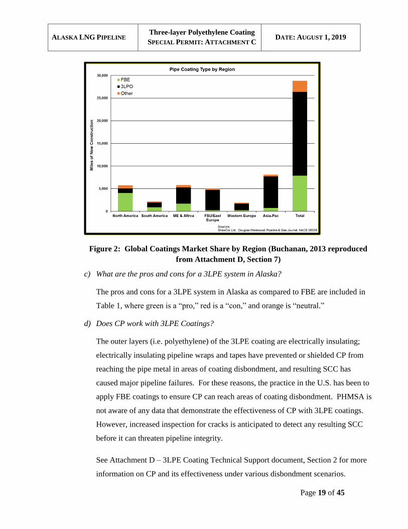
considered if FBE was to be used as the coating system. Figure 2 shows a summary
of recent coating system installations worldwide.
ALASKA LNG PIPELINE Three-layer Polyethylene Coating
SPECIAL PERMIT: ATTACHMENT C DATE: AUGUST 1, 2019
Page 19 of 45
Figure 2: Global Coatings Market Share by Region (Buchanan, 2013 reproduced
from Attachment D, Section 7)
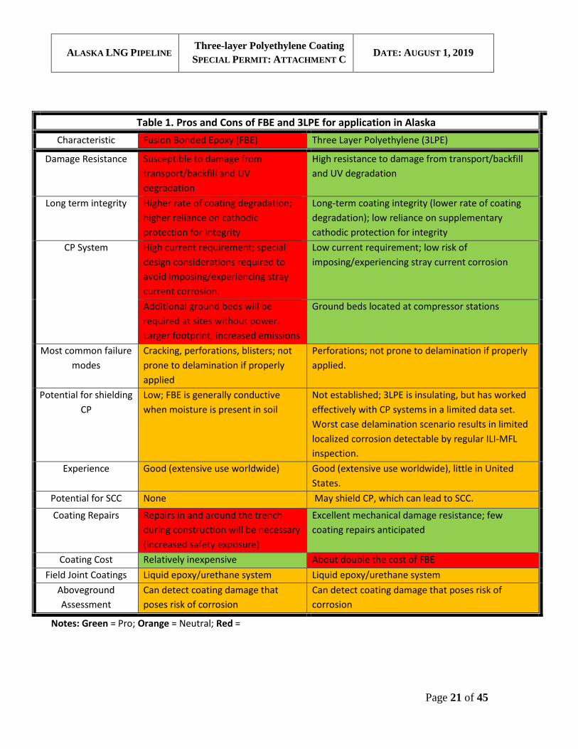
c) What are the pros and cons for a 3LPE system in Alaska?
The pros and cons for a 3LPE system in Alaska as compared to FBE are included in
Table 1, where green is a “pro,” red is a “con,” and orange is “neutral.”
d) Does CP work with 3LPE Coatings?
The outer layers (i.e. polyethylene) of the 3LPE coating are electrically insulating;
electrically insulating pipeline wraps and tapes have prevented or shielded CP from
reaching the pipe metal in areas of coating disbondment, and resulting SCC has
caused major pipeline failures. For these reasons, the practice in the U.S. has been to
apply FBE coatings to ensure CP can reach areas of coating disbondment. PHMSA is
not aware of any data that demonstrate the effectiveness of CP with 3LPE coatings.
However, increased inspection for cracks is anticipated to detect any resulting SCC
before it can threaten pipeline integrity.
See Attachment D – 3LPE Coating Technical Support document, Section 2 for more
information on CP and its effectiveness under various disbondment scenarios.
ALASKA LNG PIPELINE Three-layer Polyethylene Coating
SPECIAL PERMIT: ATTACHMENT C DATE: AUGUST 1, 2019
Page 20 of 45
e) Are over the line CP testing techniques (direct current voltage gradient (DCVG),
close inspection survey (CIS), etc.) effective in finding coating damage with 3LPE
coatings? Is there anything different with 3LPE coatings that would impair the
resultant over the line data? What will these techniques find, and miss with 3LPE
(e.g. disbondment vs. break in coating)?
The same over the pipeline inspection techniques [Close Interval Survey (CIS), Direct
Current Voltage Gradient (DCVG) and Alternating Current Voltage Gradient (ACVG)]
utilized for FBE are equally effective with 3LPE and will be implemented in compliance
with the requirements of 49 CFR 192.620 in areas where alternative MAOP and SBD are
utilized, at a minimum. For any coating system, over the line inspection, CP with
periodic monitoring and remediation, coupled with in-line-inspection are the most
effective ways to inspect, monitor, and remediate for coating integrity and corrosion. See
Attachment D, Section 6 for further discussion of the utility of over-the-line surveillance
techniques with 3LPE coated pipelines.
f) What In-Line Inspection technology will be used to detect SCC?
EMAT in-line inspection tool will be run to inspect for SCC. Additional details on
Integrity management for SCC can be found in the special permit conditions.
ALASKA LNG PIPELINE Three-layer Polyethylene Coating
SPECIAL PERMIT: ATTACHMENT C DATE: AUGUST 1, 2019
Page 21 of 45
Table 1. Pros and Cons of FBE and 3LPE for application in Alaska
Characteristic Fusion Bonded Epoxy (FBE) Three Layer Polyethylene (3LPE)
Damage Resistance Susceptible to damage from
transport/backfill and UV
degradation
High resistance to damage from transport/backfill
and UV degradation
Long term integrity Higher rate of coating degradation;
higher reliance on cathodic
protection for integrity
Long-term coating integrity (lower rate of coating
degradation); low reliance on supplementary
cathodic protection for integrity
CP System High current requirement; special
design considerations required to
avoid imposing/experiencing stray
current corrosion.
Low current requirement; low risk of
imposing/experiencing stray current corrosion
Additional ground beds will be
required at sites without power.
Larger footprint, increased emissions
Ground beds located at compressor stations
Most common failure
modes
Cracking, perforations, blisters; not
prone to delamination if properly
applied
Perforations; not prone to delamination if properly
applied.
Potential for shielding
CP
Low; FBE is generally conductive
when moisture is present in soil
Not established; 3LPE is insulating, but has worked
effectively with CP systems in a limited data set.
Worst case delamination scenario results in limited
localized corrosion detectable by regular ILI-MFL
inspection.
Experience Good (extensive use worldwide) Good (extensive use worldwide), little in United
States.
Potential for SCC None May shield CP, which can lead to SCC.
Coating Repairs Repairs in and around the trench
during construction will be necessary
(increased safety exposure)
Excellent mechanical damage resistance; few
coating repairs anticipated
Coating Cost Relatively inexpensive About double the cost of FBE
Field Joint Coatings Liquid epoxy/urethane system Liquid epoxy/urethane system
Aboveground
Assessment
Can detect coating damage that
poses risk of corrosion
Can detect coating damage that poses risk of
corrosion
Notes: Green = Pro; Orange = Neutral; Red =
ALASKA LNG PIPELINE Three-layer Polyethylene Coating
SPECIAL PERMIT: ATTACHMENT C DATE: AUGUST 1, 2019
Page 22 of 45
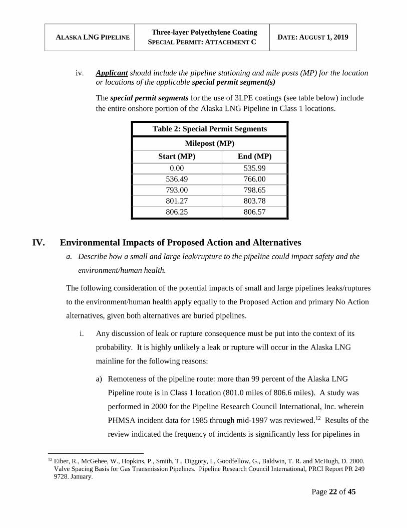
iv. Applicant should include the pipeline stationing and mile posts (MP) for the location
or locations of the applicable special permit segment(s)
The special permit segments for the use of 3LPE coatings (see table below) include
the entire onshore portion of the Alaska LNG Pipeline in Class 1 locations.
Table 2: Special Permit Segments
Milepost (MP)
Start (MP) End (MP)
0.00 535.99
536.49 766.00
793.00 798.65
801.27 803.78
806.25 806.57
IV. Environmental Impacts of Proposed Action and Alternatives
a. Describe how a small and large leak/rupture to the pipeline could impact safety and the
environment/human health.
The following consideration of the potential impacts of small and large pipelines leaks/ruptures
to the environment/human health apply equally to the Proposed Action and primary No Action
alternatives, given both alternatives are buried pipelines.
i. Any discussion of leak or rupture consequence must be put into the context of its
probability. It is highly unlikely a leak or rupture will occur in the Alaska LNG
mainline for the following reasons:
a) Remoteness of the pipeline route: more than 99 percent of the Alaska LNG
Pipeline route is in Class 1 location (801.0 miles of 806.6 miles). A study was
performed in 2000 for the Pipeline Research Council International, Inc. wherein
PHMSA incident data for 1985 through mid-1997 was reviewed.12 Results of the
review indicated the frequency of incidents is significantly less for pipelines in
12 Eiber, R., McGehee, W., Hopkins, P., Smith, T., Diggory, I., Goodfellow, G., Baldwin, T. R. and McHugh, D. 2000.
Valve Spacing Basis for Gas Transmission Pipelines. Pipeline Research Council International, PRCI Report PR 249
9728. January.
ALASKA LNG PIPELINE Three-layer Polyethylene Coating
SPECIAL PERMIT: ATTACHMENT C DATE: AUGUST 1, 2019
Page 23 of 45
Class 1 locations than in Class 2, 3 or 4. Specifically, the number of incidents per
1,000 mile-years in Class 1 Locations was 0.15 as compared with 0.24 and 0.65
for Class 2 and Class 3 and 4 Locations, respectively. When considering the
reported cause of the incident, the cause with the most significant difference in
incident rate was Damage by Outside Force. In fact, this cause was really the only
difference between Class 1 and Class 2 Locations.
b) Resilience to third party mechanical damage: there is very low risk of mechanical
damage given the remoteness of the pipeline and the high thickness of the
pipeline. Fracture mechanics calculations have shown the pipe is very resistant to
fracture, capable of withstanding a through wall thickness puncture of greater than
4 inches in length without rupturing for Class 1 locations of the pipeline designed
with AMAOP, and even longer lengths for the SBD segments and higher-Class
locations. Through wall thickness punctures of 4 inches or less will result in a
leak. The pipe will be designed to prevent a propagating fracture from occurring
in the unlikely event there was a rupture.
c) Very low probability of internal corrosion damage: The Alaska LNG Pipeline will
be transporting a dry, liquefied natural gas (LNG) specification gas, thereby
minimizing the probability of internal corrosion. To confirm the integrity of the
pipeline, the inline inspection program will comply with the robust requirements
of 49 CFR 192.620 and the special permit conditions. External corrosion will be
minimized and mitigated by using a high integrity coating and a cathodic
protection system.
d) Compliance with alternative MAOP requirements: the entire Alaska LNG
Pipeline will be operated and maintained per applicable requirements in 49 CFR
192.620 with the exception of coating requirements. Additionally, more than 615
miles of the total Alaska LNG Pipeline length will be designed, constructed,
operated and maintained to comply with applicable requirements in 49 CFR
192.112 and 192.328.
ALASKA LNG PIPELINE Three-layer Polyethylene Coating
SPECIAL PERMIT: ATTACHMENT C DATE: AUGUST 1, 2019
Page 24 of 45
ii. A small leak from a buried pipeline would result in a much slower release of gas,
when compared with a full-bore rupture, with the total amount of gas being released
dependent on the time it takes for the leak to be detected and fixed. Gas from a small
leak would permeate through the backfill material (soil) before dissipating into the
air. Small gas pipeline leaks may result in some impacts to, or loss of, surrounding
vegetation. This localized browning of vegetation can facilitate identification of
small underground leaks.
iii. A rupture would result in the rapid release of a large volume of natural gas resulting
in significant damage to the pipeline, and would create a trench or crater in the
immediate vicinity of the rupture. If an ignition source was present, an intense fire or
explosion would result.
iv. For a fire resulting from a rupture; the damage due to the fire would depend on the
extent of the combustible materials in the vicinity, (infrastructure, vegetation), and
local environmental conditions, (e.g., rain, snow cover, etc.).
b. Submit an explanation of delta/difference in safety and possible effects to the environment
between the 49 CFR Part 192 baseline (Code baseline) and usage of the special permit
conditions for multi-layer coating mitigation measures.
The anticipated differences in effects for individual resources between the No Action
alternative and the Proposed Action alternative are discussed below. The differences
are negligible. References are made to FERC Resource Reports, where applicable,
for further detailed information and analysis of impacted resources. The basis for the
FERC Resource Reports is the Proposed Action alternative; however, the associated
environmental impact analysis is also applicable to the No Action alternative, given
both alternatives are based on buried design and installation, and both follow an
identical route. In general, less long-term data is available for pipelines with 3LPE
coatings than pipelines with FBE coatings. Therefore, it is possible 3LPE may not
provide identical protection against external corrosion [and cracking], which could
increase the risk or rates of external corrosion development. However, Alaska LNG
maintains the 3LPE coating will be the most resistant to damage from shipping and
ALASKA LNG PIPELINE Three-layer Polyethylene Coating
SPECIAL PERMIT: ATTACHMENT C DATE: AUGUST 1, 2019
Page 25 of 45
handling over the long and potentially rough transport distances. Considering lesser
data availability related to external corrosion caused by coating holidays with 3LPE
coating, PHMSA will impose special permit conditions for Alaska LNG to
implement.
1. Human Health and Safety
As discussed above, the probability of a pipeline leak or rupture is considered low
due to several factors, largely independent of the coating system selected. While
3LPE coating has been in use for a shorter time than FBE, particularly in the U.S.
and, therefore, has less long-term data available, it has been in use for more than 20
years and, based on information available, no leaks or ruptures due to external
corrosion have been reported. Any possible increase in risk associated with the
development of SCC is mitigated through use of the additional cracking protocol,
including in line inspections and direct assessments requirements.
2. Air Quality
There will be no significant difference in emissions between the No Action and
Proposed Action alternatives. The majority of heavy equipment required for
construction in either alternative will be the same, including equipment such as
brushers and bulldozers for the clearing and leveling of the ROW, trucks for
transporting pipe, and side booms and welding trucks for pipe placement and
welding. Increased power generation will be required for the No Action alternative
given its larger CP system, although this is not likely to significantly increase overall
emissions. Operations and Maintenance activities to maintain the pipeline for the No
Action and Proposed Action alternatives would require similar equipment and
personnel.
Detailed descriptions of air emissions, including greenhouse gas emissions, from
pipeline construction and operations are contained in FERC Resource Report No. 9,
Air and Noise Quality.
3. Aesthetics
ALASKA LNG PIPELINE Three-layer Polyethylene Coating
SPECIAL PERMIT: ATTACHMENT C DATE: AUGUST 1, 2019
Page 26 of 45
There will be no difference in visual effects between the No Action and Proposed
Action alternatives. Visual effects from both will be limited to the ROW clearance,
which would be less obvious with winter snow cover.
Analysis of potential impacts to aesthetics, and associated mitigations, from a buried
pipeline are considered in FERC Resource Report No. 8, Land Use, Recreation and
Aesthetics.
4. Biological Resources (including vegetation, wetlands, and wildlife)
There will be no difference in impacts to vegetation, wetlands and wildlife between
the between the No Action and Proposed Action alternatives. Both alternatives will
be below ground, and follow the same route.
FERC Resource Report No. 3, Fish, Wildlife and Vegetation, contains descriptions of
vegetation and wildlife resources, and potential impacts associated with the Alaska
LNG Pipeline route. FERC Resource Report No. 2, Water Use and Quality, contains
a detailed analysis of wetlands affected by the Alaska LNG Pipeline route, and
mitigation of impacts.
5. Resilience and Adaptation
The potential effects of a changing climate on Alaska LNG Pipeline design and
operation are not expected to differ between the No Action and Proposed Action
alternatives. Project design criteria incorporated consideration of a range of variable
site conditions that could occur based upon historic information and future conditions.
Mitigations are integrated into the design where appropriate or required for facility
integrity and safe operations. Opportunities for resilience and adaptation to potential
weather effects have been considered in the design of the Alaska LNG Pipeline. For
example, geothermal modeling will be used to assess potential changes in ground
temperatures that could be caused by longer-term geothermal impacts of pipeline
construction, operations and changes in climate. Other resilience and adaptation
design considerations for the Alaska LNG Pipeline are addressed in FERC Resource
Report No. 1, General Project Description.
ALASKA LNG PIPELINE Three-layer Polyethylene Coating
SPECIAL PERMIT: ATTACHMENT C DATE: AUGUST 1, 2019
Page 27 of 45
FERC Resource Report No. 9, Air and Noise Quality discusses greenhouse gas
emissions from the Project.
6. Cultural Resources
There will be no difference in the effect on Cultural Resources between the No
Action and Proposed Action alternatives. Construction activities have the potential to
affect cultural resources. Ground-clearing activities under both cases will be similar.
The FERC is conducting the Section 106 consultation process with stakeholders; that
process will lead to the development of an agreement that will address identification
and management of known cultural resources as well as those that are inadvertently
discovered during project implementation. The cultural resource requirements will
apply to both the No Action and Proposed Action alternatives to mitigate effects on
these resources. FERC Resource Report No. 6, Cultural Resources, addresses
cultural resources affected by the Project, and associated mitigations.
7. Environmental Justice
Since both pipeline designs will be sited in the same footprint, there will be no
difference in effects on environmental justice resulting from construction or operation
of the pipeline between the No Action and Proposed Action alternatives.
8. Geology, Soils and Mineral Resources
There will be no difference in the effect on Geology, Soils and Mineral Resources
between the No Action and Proposed Action Alternatives. Construction activities
have the potential to affect soils in a localized manner with minimal effect on regional
geology or mineral resources. Construction activities that could contribute to erosion
include clearing and grading, excavation trenching, stockpile management,
backfilling, and the development of gravel pads. Most erosion effects are effectively
managed using erosion and sediment control measures, including, where appropriate:
• The use of winter construction in areas of inundated and frozen ground
conditions where practicable;
ALASKA LNG PIPELINE Three-layer Polyethylene Coating
SPECIAL PERMIT: ATTACHMENT C DATE: AUGUST 1, 2019
Page 28 of 45
• Use of settlement basins, silt fences, and other Best Management Practices
(BMP) for storm water control;
• Use of engineered flow diversions and slope breakers to control water flow on
slopes and around water courses; and
• Installation of trench breakers to address storm and groundwater flow through
the trench backfill or during construction.
Operations and maintenance activities along the pipeline right-of-way to meet 49
CFR Part 192 will be similar for the two alternatives. Operation and maintenance
excavations will be conducted as authorized under the applicable ROW
authorization. ROWs will be issued by one or both of the Bureau of Land
Management and Alaska Department of Natural Resources as the land
management agencies responsible for lands along the pipeline route. All
excavations and other applicable activities will be permitted through the
appropriate Federal and State agencies for both alternatives. Both alternatives will
have similar impacts on soil resources.
A more detailed discussion of impacts to soils and erosion resulting from the
pipeline construction and the potential mitigation measures to address those
impacts is contained in FERC Resource Report No. 7, Soils.
9. Indian Trust Assets
No Indian Trust Assets or Native allotments are located within the pipeline route.
10. Land Use, Subsistence, and Recreation
There will be no difference in the effect on Land Use, Subsistence, and Recreation
between the No Action and Proposed Action alternatives. During construction, land
use in the form of subsistence activities and recreation for both alternatives could be
altered in the immediate vicinity of activities. The pipeline’s remote location
combined with the relatively small width of the ROW will generally limit the extent
of displacement by users to the active construction zones.
ALASKA LNG PIPELINE Three-layer Polyethylene Coating
SPECIAL PERMIT: ATTACHMENT C DATE: AUGUST 1, 2019
Page 29 of 45
After construction, the ROW will be graded and revegetated to a stable condition. No
long term linear access along the pipeline alignment is proposed. However, under
either alternative, PHMSA regulations will require that the pipeline ROW is brushed
to prevent the growth of large vegetation over and around the pipeline to maintain a
clearly defined ROW.
FERC Resource Report No. 8, Land Use, Recreation and Aesthetics, considers
potential effects to land use and recreation activities. FERC Resource Report No. 5,
Socioeconomics, considers potential impacts to subsistence.
11. Noise
There will be no difference in Noise Impacts between the No Action and Proposed
Action alternatives. Impacts will generally be limited to the sounds of construction
equipment operations; human use of the area is transient and limited resulting in a
relatively short duration of effect, (transiting the area). Wildlife could also be
affected by construction-related noise. Noise related to operation of the pipeline itself
will primarily result from operation of compressor and heater stations, and periodic
ROW maintenance and inspection activities. Compression requirements are the same
for both alternatives, so there is no change to the number of compressor and heater
stations and the associated noise profile.
A detailed discussion of noise impacts associated with pipeline construction and
operation is provided in FERC Resource Report No. 9, Air and Noise Quality.
12. Water Resources
There will be no difference in impacts to water resources between the No Action and
the Proposed Action alternatives. For both alternatives, stabilization techniques,
including gravel blankets, riprap, gabions, or geosynthetics as appropriate for the
location, will be used to stabilize the channel bed and stream banks at stream
crossings. The majority of rivers and streams along the pipeline route will be crossed
by an open-cut method during winter months when flows are lowest and disturbance
of the channel and stream bank can be minimized. Burial depths for crossings have
ALASKA LNG PIPELINE Three-layer Polyethylene Coating
SPECIAL PERMIT: ATTACHMENT C DATE: AUGUST 1, 2019
Page 30 of 45
been based on site specific calculations to avoid the potential for scour. Methods for
each watercourse crossing are the same for both alternatives.
A detailed discussion regarding the management of water during construction and
operation of the pipeline and impacts to ground and surface water flow and quality
resulting from the construction and operation of the pipeline is presented in FERC
Resource Report No. 2, Water Use and Quality.
With the special permit conditions in place, PHMSA believes the Proposed Action
alternative will result in the same protection against external corrosion and cracking
as the No Action alternative. Therefore, PHMSA does not anticipate any change in
risk to the above resources could be caused by a pipeline failure resulting from
external corrosion or stress corrosion cracking.
c. Describe safety protections provided by the special permit conditions.
i. What factors were considered to ensure the conditions are adequate to protect against
waiving protections of the code.
The successful use of either FBE with ARO coating or 3LPE coating systems requires
that coating application, inspection and quality assurance procedures lead to a high-
quality coating with good adhesion of the coating to the pipe. Similarly, field joint
coatings will be liquid epoxy or epoxy-urethane material and compatible with the
coating system and the quality of the field joint coating must be ensured (See
Attachment D, Section 5).
The function of a coating system is to protect the pipeline from corrosion. The effect
of coating type on susceptibility to corrosion and stress corrosion cracking was also
considered.
Coating damage will be repaired in a manner similar to the field joint application
procedure. The damage area will be cleaned. The exposed FBE will be prepared to
remove non-adhering coating. The area will be preheated to remove moisture. The
polyethylene immediately adjacent to the damage will be cleaned by solvent wipe and

ALASKA LNG PIPELINE Three-layer Polyethylene Coating
SPECIAL PERMIT: ATTACHMENT C DATE: AUGUST 1, 2019
Page 31 of 45
roughened as needed to increase surface adhesion. The liquid epoxy or epoxy-
urethane coating will be applied in accordance with approved procedures.
ii. What are the safety and environmental risks from usage of 3LPE that need to be
protected against?
The safety and environmental risks associated with the Proposed Action will result
from a change to the risk of a leak or rupture and the subsequent release of gas and
possible explosion or fire. The risk of leak or rupture can be affected by coating
performance because external corrosion and stress corrosion cracking are failure
mechanisms that require failure of the coating. To ensure this benefit is achieved,
compliance with the special permit conditions, including ensuring coating application
procedures are qualified and adequate quality control is applied and a crack detection
protocol is in place, is necessary.
d. Explain the basis for the particular set of alternative mitigation measures used in the
special permit conditions. Explain whether the measures will ensure that a level of safety
and environmental protection equivalent to compliance with existing regulations is
maintained.
i. The special permit conditions were designed to ensure best practices and application,
testing and quality control for plant applied and field joint coating are applied.
The conditions were designed to reduce the risk of SCC. Although there is no history
that indicates pipelines coated with 3LPE are susceptible to SCC, EMAT in-line
inspection is required by the conditions to ensure this threat will be detected before it
will lead to leak or rupture of the pipeline. The use of the above measures helps to
ensure that no significant environmental impact will result from the use of 3LPE. It is
anticipated that the higher initial coating integrity and reduced rate of coating
degradation with the use of 3LPE will lead to an overall improvement in pipeline
safety and reduce potential environmental impact.
ALASKA LNG PIPELINE Three-layer Polyethylene Coating
SPECIAL PERMIT: ATTACHMENT C DATE: AUGUST 1, 2019
Page 32 of 45
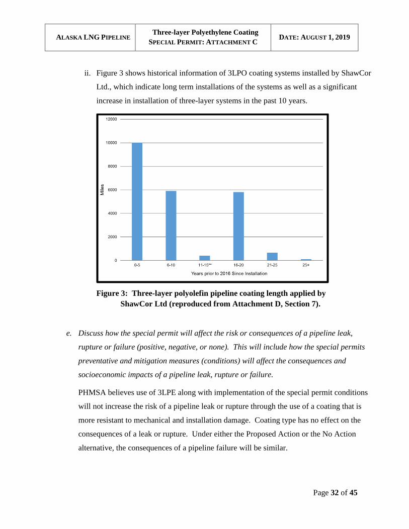
ii. Figure 3 shows historical information of 3LPO coating systems installed by ShawCor
Ltd., which indicate long term installations of the systems as well as a significant
increase in installation of three-layer systems in the past 10 years.
Figure 3: Three-layer polyolefin pipeline coating length applied by
ShawCor Ltd (reproduced from Attachment D, Section 7).
e. Discuss how the special permit will affect the risk or consequences of a pipeline leak,
rupture or failure (positive, negative, or none). This will include how the special permits
preventative and mitigation measures (conditions) will affect the consequences and
socioeconomic impacts of a pipeline leak, rupture or failure.
PHMSA believes use of 3LPE along with implementation of the special permit conditions
will not increase the risk of a pipeline leak or rupture through the use of a coating that is
more resistant to mechanical and installation damage. Coating type has no effect on the
consequences of a leak or rupture. Under either the Proposed Action or the No Action
alternative, the consequences of a pipeline failure will be similar.
ALASKA LNG PIPELINE Three-layer Polyethylene Coating
SPECIAL PERMIT: ATTACHMENT C DATE: AUGUST 1, 2019
Page 33 of 45
f. Discuss any effects on pipeline longevity and reliability such as life-cycle and periodic
maintenance including integrity management. Discuss any technical innovations as well.
Implementation of the special permit conditions will positively impact pipeline longevity
and reliability by reducing coating degradation, monitoring threats, and the implementation
of remediation measures for 3LPE coating degradation and other related pipeline integrity
threats.
PHMSA believes the approach for integrity management and maintenance of the pipeline is
similar for the Proposed Action and No Action alternatives. However, the special permit
conditions require additional inspection, and testing during the coating application, and
more robust in-line inspection and assessment requirements during Operation and
Maintenance for the Proposed Action alternative.
g. Discuss how the special permit would impact human safety.
Several layers of protection are utilized to prevent pipeline failures due to corrosion:
i. The coating system prevents external corrosion by acting as a barrier between ground
water, oxygen, and the steel pipe.
ii. The cathodic protection system prevents corrosion at any breaks in the coating.
iii. In-line inspection detects wall loss and cracking type defects allowing repair before
failure.
The use of 3LPE and compliance with the special permit conditions are expected to
positively impact the effectiveness of the first two items above. Reduced coating damage
and slower coating degradation are expected to lead to fewer coating defects. The higher
integrity of the 3LPE coatings are expected to lead to reduced current demand on the
cathodic protection system and reduced risk of interference with neighboring structures.
Thus, the special permit is expected to improve human safety by reducing the overall
likelihood of failure and the potential for injury from the resulting release of gas.
ALASKA LNG PIPELINE Three-layer Polyethylene Coating
SPECIAL PERMIT: ATTACHMENT C DATE: AUGUST 1, 2019
Page 34 of 45
h. Discuss whether the special permit would affect land use planning.
Special permit status will not change land use planning processes, given that the Proposed
Action and No Action alternatives will both be premised a belowground basis. The ROW
authorization requirements, and other land use planning notification processes will be the
same with or without a special permit.
i. Discuss any pipeline facility, public infrastructure, safety impacts and/or environmental
impacts associated with implementing the special permit. In particular, discuss how any
environmentally sensitive areas could be impacted.
The “No Action alternative” may require a small increase in size and number of anode
ground beds to accommodate the possible higher CP current requirements of an FBE
coating pipeline due to anticipated higher total current demand based on the difference in
coating breakdown factors. Implementation of the special permit will not affect any other
pipeline facilities, public infrastructure, or environmentally sensitive areas.
j. What scenario would be required for CP shielding leading to corrosion or SCC to occur?
How likely are these scenarios?
In the event that the coating disbondments occur, it is possible that the 3LPE coatings could
shield uncoated pipe from CP, which could lead to SCC over time. For this reason, AGDC
will be required to run an EMAT tool, which exceeds current regulatory requirements. See
Attachment D, Section 3 for a discussion of shielding and Section 4 for a discussion of
SCC scenarios.
k. Based on industry experience, 1) has SCC occurred with 3LPO coatings and what 2)
mitigation and 3) detection techniques will be employed?
1) Industry experience has not identified any instances of SCC with 3LPO coatings. See
Attachment D, Section 9 for a summarized record of the Applicant’s discussions with
various pipeline operators. In addition, DNV GL was contracted to perform a search of
global literature and pipeline operator data and did not identify any instances of SCC with
3LPE coatings.
ALASKA LNG PIPELINE Three-layer Polyethylene Coating
SPECIAL PERMIT: ATTACHMENT C DATE: AUGUST 1, 2019
Page 35 of 45
2) Mitigation: Stringent quality assurance and quality control (QA/QC) measures will be
employed during 3LPE coating application. The surface will be prepared by abrasive grit
blasting, which imparts a compressive stress on the surface of the metal that is recognized
to provide resistance to SCC. See Attachment D, Section 5 for more information on the
QA/QC of 3LPE coatings.
3) Detection: EMAT and high resolution magnetic flux leakage (HR-MFL) in line
inspection tools will be utilized to detect SCC and general corrosion.13
l. What survey techniques will be used during Operations?
The same survey techniques will be used during the construction and maintenance of 3LPE
as with any other coating system:
• DCVG and CIS as part of commissioning the cathodic protection system as well
as ongoing surveillance.
• ILI baseline upon commissioning and ongoing inspection in accordance with 49
CFR Part 192, Subpart O. The ILI tool results must address ILI tool tolerances.
Fracture mechanics analysis must be performed to evaluate cracking indications
reported by ILI or direct examinations. All cracking exceeding 40% of the pipe
wall thickness or with a failure pressure ratio (FPR) below the criteria in 49 CFR
192.620(d)(11) must be remediated. The special permit conditions have the crack
evaluation details.
m. What is the threat from interference initiated corrosion (e.g. Alternating Current (AC)
interference, Direct Current (DC) interference, stray current, telluric) and how do we plan
to monitor and mitigate it?
Electrical interference assessment, monitoring and mitigation are key aspects of pipeline
and cathodic protection design, and will be addressed during the detailed engineering
stages, in accordance with the special permit conditions and applicable requirements in 49
13 Although the utilization of a high resolution magnetic flux leakage (HR-MFL) in-line inspection (ILI) tool is not a
proposed condition of this special permit application, PHMSA will require the use of this tool in the special permit for
the use of strain based design (SBD) on the Alaska LNG Pipeline.
ALASKA LNG PIPELINE Three-layer Polyethylene Coating
SPECIAL PERMIT: ATTACHMENT C DATE: AUGUST 1, 2019
Page 36 of 45
CFR Part 192. Each type of interference (stray current, AC interference, and telluric) will
be evaluated and, where necessary, electrical interference mitigation systems will be
designed and installed. These actions are expected to confirm the functionality and
adequacy of CP, which is critical for pipeline integrity by preventing corrosion in areas of
coating disbondment.
Alaska LNG will implement a monitoring program and remediation plan in accordance
with 49 CFR Part 192, Subpart I and the special permit conditions.
AC Interference
AC interference can occur where pipelines are in close proximity to AC electric power
transmission system lines; particularly where pipelines are approximately parallel to power
lines. AC interference can occur during steady-state operation of power lines and during
fault conditions on power lines.
The electrical interference monitoring program and remediation plan will mitigate AC
interference by identifying exposures, identifying changes in power line operating
conditions that could cause or increase interference, and providing for mitigation to reduce
interference to acceptable levels. Mitigation can include installation of AC interference
mitigation grounding cells and parallel ribbons, potential gradient control mats and DC
decoupling devices.
DC Interference
DC interference can be caused by several sources, such as foreign IC CP systems, DC
electric power transmission systems, DC traction power systems and welding operations.
Some sources of DC interference are considered to be steady-state sources (such as foreign
IC CP systems), and some are considered to be stray sources (such as DC electric power
transmission systems, DC traction power systems and welding operations).
The electrical interference monitoring program and remediation plan will facilitate
mitigation of DC interference by identifying interference, by identifying the sources of
interference, and by providing for mitigation to reduce interference to acceptable levels.
Mitigation can include careful selection of sites for IC CP systems, collaborated adjustment
ALASKA LNG PIPELINE Three-layer Polyethylene Coating
SPECIAL PERMIT: ATTACHMENT C DATE: AUGUST 1, 2019
Page 37 of 45
of native and foreign IC CP systems, installation of bonds with interfering DC sources,
installation of galvanic anode current drains, and dielectric shielding (use of robust
coatings in areas of anticipated or known interference exposures).
Telluric Current Interference
Telluric current interference is electrical interference that results from the interaction of a
pipeline with the earth’s magnetic field and solar radiation passing around the earth. The
interaction creates electric fields in and around a pipeline which result in DC voltages and
current flow on the pipeline. Fluctuations in DC voltages and current flow caused by
telluric activity are very low frequency electrical phenomena.
Telluric current interference does not normally cause significant corrosion damage on
pipelines, but it can under certain conditions and/or over long periods of time. Pipe-to-soil
potential data collected during annual CP surveys will be used to monitor for telluric
current interference. When these pipe-to-soil potential measurements are made, telluric
current interference will readily be detected if it causes fluctuations in pipe-to-soil potential
measurements.
As a minimum telluric current interference will be mitigated in a manner that will achieve
pipe-to-soil potentials in compliance with 49 CFR Part 192 Subpart I. Mitigation can
include installation of galvanic anode current drains and installation of automatic potential
control IC CP system rectifiers at exposure locations.
Locations and types of CP test stations to be installed for operational monitoring of CP and
electrical interference will be determined during the detailed design phase of engineering
for the Project. Determination of test station requirements will be performed following
pipeline industry standards and regulatory requirements for special permit pipelines. As a
minimum for special permit segments of the pipeline, test stations will be installed as
follows:
• At least once every mile;
• At crossings of buried foreign metallic structures; and
ALASKA LNG PIPELINE Three-layer Polyethylene Coating
SPECIAL PERMIT: ATTACHMENT C DATE: AUGUST 1, 2019
Page 38 of 45
• On each side of major waterbody crossings.
Coupons will generally be installed at each test station, except at locations where coupons
will not function as intended (e.g. in permafrost). Coupons are used to determine the
amount of voltage gradient (IR drop) in the soil when the CP systems are energized (or
connected, in the case of sacrificial anodes). Use of coupons for this purpose is common
practice for complex or hybrid CP systems where it is difficult to effectively obtain IR-free
potential measurements by cycling the entire CP system on/off at the same time.
Remote monitoring will be installed to provide real time CP operating outputs. The
specific products and frequency of installation of these systems will be determined in
future Project engineering phases.
V. Consultation and Coordination
a. Please list the name, title and company of any person involved in the preparation of this
document.
PHMSA:
Amelia Samaras (Senior Attorney), Joshua Johnson (Engineer); Steve Nanney
(Engineer)
Alaska Gasline Development Corporation:
Frank Richards (Senior Vice President)
Alaska LNG LLC:
Rick Noecker (PHMSA Filing Coordinator), Alyssa Samson (Materials Engineer),
Mario Macia (Pipeline Technology Lead), Norm Scott (ERL Advisor)
Michael Baker International:
Keith Meyer (Senior Pipeline Advisor), Paul Carson (Corporate Pipeline Engineer).
ALASKA LNG PIPELINE Three-layer Polyethylene Coating
SPECIAL PERMIT: ATTACHMENT C DATE: AUGUST 1, 2019
Page 39 of 45
b. Please provide names and contact information for any person or entity you know will be
impacted by the special permit. PHMSA may perform appropriate public scoping. The
applicant’s assistance in identifying these parties will speed the process considerably.
Adjacent landowner’s/land managers potentially impacted:
Cook Inlet Region, Inc.
Ben Mohr
Sr. Director, Land and Resources
P.O. Box 93330
Anchorage, AK 99509
(907) 263-5140
Bureau of Land Management
Earle Williams
BLM Alaska State Office
222 W. 7th Avenue #13
Anchorage, AK 99513-7504
(907) 271-5762
Alaska Department of Natural Resources
Thomas Stokes
State Pipeline Coordinator
3651 Penland Parkway
Anchorage, AK 99508
(907) 269-6419
Alaska Department of Transportation & Public Facilities
Joseph Kemp
Gasline Liaison
2301 Peger Road
Fairbanks, AK 99709
(907) 451-2959
ALASKA LNG PIPELINE Three-layer Polyethylene Coating
SPECIAL PERMIT: ATTACHMENT C DATE: AUGUST 1, 2019
Page 40 of 45
Brooke Merrell
Chief of Planning and Compliance
United States National Park Service, Alaska Regional Office
240 W 5th Avenue
Anchorage, AK 99501
(907) 644-3397
Don Striker
Superintendent
Denali National Park and Preserve
P.O. Box 9
Denali Park, AK 99755-0009
(907) 683-9532
c. If you have engaged in any stakeholder or public communication regarding this request,
please include information regarding this contact.
Active stakeholder engagement has occurred throughout Alaska and federal, state and
local agency engagement is ongoing. In 2015 and 2016, one-on-one as well as
multiagency engagement meetings were held to cover pipeline design construction
and routing. Additionally, there have been over 20 engagement meetings between the
Applicant and PHMSA. The coatings systems described herein were a topic of
discussion at multiple meetings, and there have been responses to several requests for
additional information on coatings systems that were made by PHMSA.
Additionally, an overview of this special permit was provided at a joint meeting with
PHMSA and FERC on April 19, 2016.
PHMSA has participated in scoping and public outreach lead by FERC related to the
Alaska LNG FERC Resource Reports. Details of the public outreach, which included
both members of tribal entities and the general public, are provided in Section 1.9 and
Appendix D of Resource Report 1 of the FERC Resource Reports.
VI. Response to Public Comments Placed on Docket PHMSA-2017-0046
PHMSA published a Notice of Availability in the Federal Register on May 28, 2019 for four (4)
special permit requests for the line pipe of the Alaska LNG Pipeline. (84 FR 24594, Docket
Nos.: PHMSA-2017-0046, Usage of 3LPE Coating; PHMSA-2017-0044, Usage of Strain Based
ALASKA LNG PIPELINE Three-layer Polyethylene Coating
SPECIAL PERMIT: ATTACHMENT C DATE: AUGUST 1, 2019
Page 41 of 45
Design; PHMSA-2017-0045, Alternative Mainline Block Valve Spacing; and PHMSA-2017-
0047, Usage of Crack Arrestor Spacing at www.Regulations.gov). PHMSA requested comment
on the special permit applications, the draft permit conditions, and the draft environmental
analyses. The public notice comment period ended on July 29, 2019, with all comments
received through July 29, 2019, being reviewed and considered. PHMSA received a public
comment concerning usage of fossil fuels, the building of the Alaska LNG Pipeline, and the
building of a liquefied natural gas (LNG) facility. PHMSA does not have siting authority over
pipeline facilities. The public comment received did not submit concerns directed towards the
special permit, the environmental assessment, or the special permit conditions, which were the
issues within PHMSA’s decision making authority and the intent of the public notice.
VII. Finding of No Significant Impact
Although technically distinct, PHMSA considered the combined impacts and safety risks
associated with the issuance and implementation of the special permits, including the special
permit conditions, for usage of 3LPE coating, usage of strain based design, alternative spacing
of mainline block valves, and alternative spacing of crack arrestors. PHMSA finds that special
permits and associated special permit conditions will not impose a significant impact on the
human environment. The special permit conditions are designed to be consistent with pipeline
safety and to ensure the same or a greater level of safety as will be achieved if the pipeline were
designed, constructed, operated, and maintained in full compliance with 49 CFR Part 192.
VIII. Bibliography
Applicant to document information submitted, if they consulted a book, website, or other
document to answer the question, please provide a citation.
See footnotes.
IX. Conditions: Example of what special permit conditions address
a. Plant-applied coating system qualification and testing: What will be done to ensure the
long-term integrity of the coating and the disbondment failures will not occur?
ALASKA LNG PIPELINE Three-layer Polyethylene Coating
SPECIAL PERMIT: ATTACHMENT C DATE: AUGUST 1, 2019
Page 42 of 45
To ensure the integrity benefits of 3LPE coatings are achieved, the conditions require best
practices be applied to the qualification of the coating system. The qualification will
require each plant used for the application of coatings be qualified separately. The
qualified coating procedure and qualification testing must reflect the industry best practices
that are included in ISO 21809-114, a global standard for 3LPO coatings. Periodic testing
during coating application (production testing) confirms the properties achieved during
qualification continue to be achieved.
The coating application procedure will be in accordance with requirements of ISO 21809-1,
and will include details on the following:
a) Incoming inspection of pipes and pipe tracking.
b) Data sheets for coating materials and abrasive blasting materials.
c) Certification, receipt, handling and storage of materials for coating and abrasive
blasting.
d) Cleaning procedure for application equipment.
e) Preparation of the steel surface including monitoring of environmental parameters,
methods and tools for inspection, grinding of pipe surface defects and testing of surface
preparation.
f) Coating application, including tools/equipment for control of process parameters
essential for the quality of the coating.
g) Methods and tools/equipment for inspection and testing of the applied coating.
h) Repairs of coating defects and any associated inspection and testing.
i) Preparation of coating cutback areas.
j) Marking and traceability.
Qualification and production testing required by ISO 21809-1 includes:
• Inspection of surface preparation;
• Minimum epoxy thickness;
14 ISO 21809-1 (2011) Petroleum and natural gas industries - External coatings for buried or submerged pipelines used in
pipeline transportation systems Part 1: Polyolefin coatings (3-layer PE and 3- layer PP)
ALASKA LNG PIPELINE Three-layer Polyethylene Coating
SPECIAL PERMIT: ATTACHMENT C DATE: AUGUST 1, 2019
Page 43 of 45
• Minimum adhesive thickness;
• Degree of cure;
• Continuity (holiday detection);
• Total thickness of coating;
• Impact resistance;
• Peel strength;
• Indentation;
• Elongation at break;
• Cathodic disbondment;
• Hot water immersion test; and
• Flexibility.
b. Field Joint coating system qualification and testing: What will be done to ensure the long-
term integrity of the field joint coating?
Field joint coating systems are used to coat girth welds made in the field and the adjacent
pipe ends. Ensuring the success of the coating system requires the field joint coating
system achieve high integrity and the field joint coating system is compatible with the
plant-applied system. The conditions require the qualification of the field joint coating
procedure that will be used.
The conditions require that the field joint coating application procedure describe the
following:
• Method for surface preparation and required surface profile;
• Method for heating the pipe and monitoring temperature;
• Nominal steel temperature for application of field joint coating and permitted range;
• Manufacturer and brand name of product;
• Method and equipment for application of coating;
• Minimum dry film thickness; and
• Method for holiday detection and repair.
ALASKA LNG PIPELINE Three-layer Polyethylene Coating
SPECIAL PERMIT: ATTACHMENT C DATE: AUGUST 1, 2019
Page 44 of 45
The required field joint coating qualification tests include:
• Impact resistance testing;
• Hot-water soak/adhesion testing;
• Penetration resistance testing; and
• Cathodic disbondment testing.
In addition, the conditions require verification of the coating thickness on each field joint
and holiday detection for each field joint.
c. Inspection and qualification of inspectors: What will be done to ensure the qualifications of
inspectors?
The conditions require that coating and field joint coating operations are monitored by
certified coating inspectors.
d. What measures will be employed to detect SCC, if it were to occur?
There have been pipeline integrity issues due to stress corrosion cracking resulting from the
use of tape wrap, coal tar enamel, and asphalt coatings. Failures of these coatings have
occurred in a manner that has allowed ground water and oxygen to reach the pipe steel
surface, but blocked CP current (i.e., caused “CP shielding”). The 3LPE coating system is
a modern coating system that has not been associated with the occurrence of similar issues.
However, there is limited experience with 3LPE service times greater than 20 years. The
conditions contain provisions that ensure the threat of SCC will be assessed throughout the
life of the pipeline to ensure if long-term (i.e., 20+ years) use of these coatings leads to
increased susceptibility to SCC, the threat will be identified and managed before it leads to
leaks or ruptures of the pipeline.
The special permit conditions require periodic in-line inspection with a crack detection tool
to identify whether SCC is an integrity threat to the Alaska LNG pipeline. Electromagnetic
Acoustic Transducer (EMAT) is the crack detection tool required by the special permit
conditions.
ALASKA LNG PIPELINE Three-layer Polyethylene Coating
SPECIAL PERMIT: ATTACHMENT C DATE: AUGUST 1, 2019
Page 45 of 45
Because SCC can take at least 10 years to form, it should also be understood that by the
time Project pipelines reach an age at which SCC could begin to develop, significant
additional industry experience will be available with longer term use of 3LPE coatings. As
a result, there will be a substantial global experience base available to identify whether
3LPE coated pipelines are susceptible to SCC and this additional knowledge will be
available to further inform assessments of the risk of SCC.
e. How will interference currents control be addressed?
An induced AC or DC monitoring program and remediation plan to protect the pipeline
from corrosion caused by stray or interference currents must be in place within 1 year of
the pipe in these segments being installed in the ditch (including backfill).
Within 12 months of the results of the interference engineering analysis, any AC
interference causing AC current discharge greater than 50 amperes per meter squared of
surface area must be remediated. Remediation means the implementation of performance
measures including, but not limited to, additional grounding along the pipeline to reduce
interference currents. Any DC interference that results in CP levels that do not meet the
requirements of 49 CFR Part 192, Subpart I, must be remediated within 12 months of this
evaluation.
Completed by PHMSA in Washington, DC on: September 9, 2019