Embed Size (px)
Citation preview
Final implementation of a subnanosecond rise time, variablepulse duration, variable amplitude, repetitive, high-voltagepulse sourceCitation for published version (APA):Huiskamp, T., Heesch, van, E. J. M., & Pemen, A. J. M. (2015). Final implementation of a subnanosecond risetime, variable pulse duration, variable amplitude, repetitive, high-voltage pulse source. IEEE Transactions onPlasma Science, 43(1), 444-451. https://doi.org/10.1109/TPS.2014.2374535
DOI:10.1109/TPS.2014.2374535
Document status and date:Published: 01/01/2015
Document Version:Publisher’s PDF, also known as Version of Record (includes final page, issue and volume numbers)
Please check the document version of this publication:
• A submitted manuscript is the version of the article upon submission and before peer-review. There can beimportant differences between the submitted version and the official published version of record. Peopleinterested in the research are advised to contact the author for the final version of the publication, or visit theDOI to the publisher's website.• The final author version and the galley proof are versions of the publication after peer review.• The final published version features the final layout of the paper including the volume, issue and pagenumbers.Link to publication
General rightsCopyright and moral rights for the publications made accessible in the public portal are retained by the authors and/or other copyright ownersand it is a condition of accessing publications that users recognise and abide by the legal requirements associated with these rights.
• Users may download and print one copy of any publication from the public portal for the purpose of private study or research. • You may not further distribute the material or use it for any profit-making activity or commercial gain • You may freely distribute the URL identifying the publication in the public portal.
If the publication is distributed under the terms of Article 25fa of the Dutch Copyright Act, indicated by the “Taverne” license above, pleasefollow below link for the End User Agreement:www.tue.nl/taverne
Take down policyIf you believe that this document breaches copyright please contact us at:[email protected] details and we will investigate your claim.
Download date: 05. Feb. 2022
444 IEEE TRANSACTIONS ON PLASMA SCIENCE, VOL. 43, NO. 1, JANUARY 2015
Final Implementation of a Subnanosecond RiseTime, Variable Pulse Duration, Variable Amplitude,
Repetitive, High-Voltage Pulse SourceT. Huiskamp, E. J. M. van Heesch, and A. J. M. Pemen, Member, IEEE
Abstract— In this paper, we present the final implementationof our 0–50-kV picosecond rise time 0.5–10-ns pulse generator.The pulse generator will be used in future work to generate a(sub)-nanosecond streamer plasma for air purification research.The pulse generator is a single-line pulse generator with an oilspark-gap (SG), which generates 0.5–10-ns pulses with a 200-psrise time and can operate at repetition rates of over 1 kHz intoa 50-� load. It is an improvement over the first implementationof our nanosecond pulse generator that we designed and verifiedexperimentally in previous work. In this paper, we evaluate theperformance of the final design. Furthermore, we present 3-Delectromagnetic simulations of the nanosecond pulse generatorand show that the simulations are in good agreement with themeasurements. A variation in pulse duration from 0.5 to 10 nsis possible and the output pulses are square shaped without thelarge plateau behind the main pulse that was present in the pulsesfrom the first implementation of the nanosecond pulse generator.At high voltages, the pulse top becomes less flat due to a time-dependent mismatch in the spark-gap. Furthermore, investigationof electrode erosion of the oil spark-gap shows that the erosionrate of the electrodes is in the range of 200–600 μcm3 ·C−1 forthe electrode that is mainly the cathode and 100–300 μcm3 ·C−1
for the electrode that is mainly the anode, respectively. This isalmost an order of magnitude higher than most gas spark-gapstudies show for brass electrodes. Therefore, electrode erosion inthe oil spark-gap will be a limiting factor on the lifetime of thesystem. We designed a new electrode with a stainless steel headto increase this lifetime.
Index Terms— 3-D electromagnetic (EM) modeling, electrodeerosion, high voltage, nanosecond pulses, oil switch, pulsed powersupply, spark-gap (SG).
I. INTRODUCTION
RECENT research has shown that plasmas generated byvery short nanosecond high-voltage pulses are very effi-
cient for a variety of applications [3]–[7]. Nonthermal plasmaproves especially useful for air purification purposes [8], [9].In our research, we will study a corona reactor in whichwe generate a streamer plasma with very short (<10 ns)high-voltage pulses for air purification.
Manuscript received June 9, 2014; revised September 29, 2014,October 21, 2014, and October 27, 2014; accepted November 20, 2014. Dateof publication December 8, 2014; date of current version January 6, 2015.This work was supported by the Dutch Technology Foundation STW underContract 10751.
The authors are with the Electrical Energy Systems Group, EindhovenUniversity of Technology, Eindhoven 5612 AZ, The Netherlands (e-mail:[email protected]; [email protected]; [email protected]).
Color versions of one or more of the figures in this paper are availableonline at http://ieeexplore.ieee.org.
Digital Object Identifier 10.1109/TPS.2014.2374535
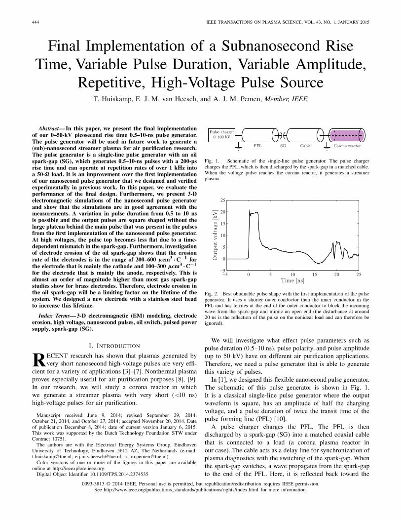
Fig. 1. Schematic of the single-line pulse generator. The pulse chargercharges the PFL, which is then discharged by the spark-gap in a matched cable.When the voltage pulse reaches the corona reactor, it generates a streamerplasma.
Fig. 2. Best obtainable pulse shape with the first implementation of the pulsegenerator. It uses a shorter outer conductor than the inner conductor in thePFL and has ferrites at the end of the outer conductor to block the incomingwave from the spark-gap and mimic an open end (the disturbance at around20 ns is the reflection of the pulse on the nonideal load and can therefore beignored).
We will investigate what effect pulse parameters such aspulse duration (0.5–10 ns), pulse polarity, and pulse amplitude(up to 50 kV) have on different air purification applications.Therefore, we need a pulse generator that is able to generatethis variety of pulses.
In [1], we designed this flexible nanosecond pulse generator.The schematic of this pulse generator is shown in Fig. 1.It is a classical single-line pulse generator where the outputwaveform is square, has an amplitude of half the chargingvoltage, and a pulse duration of twice the transit time of thepulse forming line (PFL) [10].
A pulse charger charges the PFL. The PFL is thendischarged by a spark-gap (SG) into a matched coaxial cablethat is connected to a load (a corona plasma reactor inour case). The cable acts as a delay line for synchronization ofplasma diagnostics with the switching of the spark-gap. Whenthe spark-gap switches, a wave propagates from the spark-gapto the end of the PFL. Here, it is reflected back toward the
0093-3813 © 2014 IEEE. Personal use is permitted, but republication/redistribution requires IEEE permission.See http://www.ieee.org/publications_standards/publications/rights/index.html for more information.
HUISKAMP et al.: FINAL IMPLEMENTATION OF A SUBNANOSECOND HIGH-VOLTAGE PULSE SOURCE 445
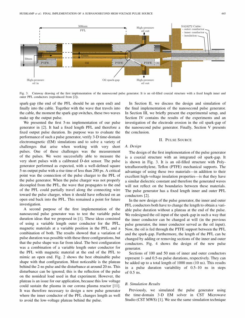
Fig. 3. Cutaway drawing of the first implementation of the nanosecond pulse generator. It is an oil-filled coaxial structure with a fixed length inner andouter PFL conductors (reproduced from [2]).
spark-gap (the end of the PFL should be an open end) andfinally into the cable. Together with the wave that travels intothe cable, the moment the spark-gap switches, these two wavesmake up the output pulse.
We presented the first 5-ns implementation of our pulsegenerator in [2]. It had a fixed length PFL and therefore afixed output pulse duration. Its purpose was to evaluate theperformance of such a pulse generator, verify 3-D time-domainelectromagnetic (EM) simulations and to solve a variety ofchallenges that arise when working with very shortpulses. One of these challenges was the measurementof the pulses. We were successfully able to measure thevery short pulses with a calibrated D-dot sensor. The pulsegenerator performed as expected, with a well-defined square5-ns output pulse with a rise time of less than 200 ps. A criticalpoint was the connection of the pulse charger to the PFL ofthe pulse generator. When the pulse charger was not properlydecoupled from the PFL, the wave that propagates to the endof the PFL could partially travel along the connecting wiretoward the pulse charger, when it should have reflected on anopen end back into the PFL. This remained a point for futureinvestigation.
A second purpose of the first implementation of thenanosecond pulse generator was to test the variable pulseduration ideas that we proposed in [1]. These ideas consistedof using a variable length outer conductor for the PFL,magnetic materials at a variable position in the PFL, and acombination of both. The results showed that a variation ofpulse duration was possible with these three configurations, butthat the pulse shape was far from ideal. The best configurationwas a combination of a variable length outer conductor forthe PFL with magnetic material at the end of the PFL tomimic an open end. Fig. 2 shows the best obtainable pulseshape with that configuration. Most noticeable is the plateaubehind the 2-ns pulse and the disturbance at around 20 ns. Thisdisturbance can be ignored; this is the reflection of the pulseon the nonideal load used in that experiment. However, theplateau is an issue for our application, because this low voltagecould sustain the plasma in our corona plasma reactor [11].It was therefore necessary to design a new pulse generatorwhere the inner conductor of the PFL changes length as wellto avoid the low-voltage plateau behind the pulse.
In Section II, we discuss the design and simulation ofthe final implementation of the nanosecond pulse generator.In Section III, we briefly present the experimental setup, andSection IV contains the results of the experiments and aninvestigation of the electrode erosion in the oil spark-gap ofthe nanosecond pulse generator. Finally, Section V presentsthe conclusion.
II. PULSE SOURCE
A. Design
The design of the first implementation of the pulse generatoris a coaxial structure with an integrated oil spark-gap. Itis shown in Fig. 3. It is an oil-filled structure with Poly-tetrafluoroethylene, Teflon (PTFE) mechanical supports. Theadvantage of using these two materials—in addition to theirexcellent high-voltage insulation properties—is that they havea similar dielectric constant and therefore the generated waveswill not reflect on the boundaries between these materials.The pulse generator has a fixed length inner and outer PFLconductors [2].
In the new design of the pulse generator, the inner and outerPFL conductors both have to change the length to obtain a vari-able pulse duration without a plateau at the end of the pulse.We redesigned the oil input of the spark-gap in such a way thatthe inner conductor can be changed at will (in the previouspulse generator, the inner conductor served as the oil input).Now, the oil is fed through the PTFE support between the PFLand the spark-gap. Furthermore, the length of the PFL can bechanged by adding or removing sections of the inner and outerconductors. Fig. 4 shows the design of the new pulsegenerator.
Sections of 100 and 50 mm of inner and outer conductorsrepresent 1- and 0.5-ns pulse durations, respectively. They canbe added up to a total length of 1000 mm (10 ns). This resultsin a pulse duration variability of 0.5–10 ns in stepsof 0.5 ns.
B. Simulation Results
Previously, we simulated the pulse generator usingthe time-domain 3-D EM solver in CST MicrowaveStudio (CST MWS) [1]. We use the same simulation technique
446 IEEE TRANSACTIONS ON PLASMA SCIENCE, VOL. 43, NO. 1, JANUARY 2015
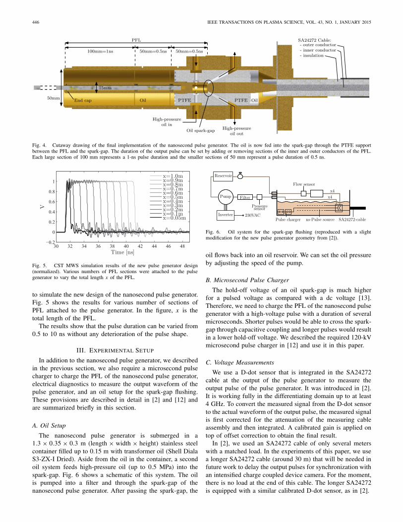
Fig. 4. Cutaway drawing of the final implementation of the nanosecond pulse generator. The oil is now fed into the spark-gap through the PTFE supportbetween the PFL and the spark-gap. The duration of the output pulse can be set by adding or removing sections of the inner and outer conductors of the PFL.Each large section of 100 mm represents a 1-ns pulse duration and the smaller sections of 50 mm represent a pulse duration of 0.5 ns.
Fig. 5. CST MWS simulation results of the new pulse generator design(normalized). Various numbers of PFL sections were attached to the pulsegenerator to vary the total length x of the PFL.
to simulate the new design of the nanosecond pulse generator.Fig. 5 shows the results for various number of sections ofPFL attached to the pulse generator. In the figure, x is thetotal length of the PFL.
The results show that the pulse duration can be varied from0.5 to 10 ns without any deterioration of the pulse shape.
III. EXPERIMENTAL SETUP
In addition to the nanosecond pulse generator, we describedin the previous section, we also require a microsecond pulsecharger to charge the PFL of the nanosecond pulse generator,electrical diagnostics to measure the output waveform of thepulse generator, and an oil setup for the spark-gap flushing.These provisions are described in detail in [2] and [12] andare summarized briefly in this section.
A. Oil Setup
The nanosecond pulse generator is submerged in a1.3 × 0.35 × 0.3 m (length × width × height) stainless steelcontainer filled up to 0.15 m with transformer oil (Shell DialaS3-ZX-I Dried). Aside from the oil in the container, a secondoil system feeds high-pressure oil (up to 0.5 MPa) into thespark-gap. Fig. 6 shows a schematic of this system. The oilis pumped into a filter and through the spark-gap of thenanosecond pulse generator. After passing the spark-gap, the
Fig. 6. Oil system for the spark-gap flushing (reproduced with a slightmodification for the new pulse generator geometry from [2]).
oil flows back into an oil reservoir. We can set the oil pressureby adjusting the speed of the pump.
B. Microsecond Pulse Charger
The hold-off voltage of an oil spark-gap is much higherfor a pulsed voltage as compared with a dc voltage [13].Therefore, we need to charge the PFL of the nanosecond pulsegenerator with a high-voltage pulse with a duration of severalmicroseconds. Shorter pulses would be able to cross the spark-gap through capacitive coupling and longer pulses would resultin a lower hold-off voltage. We described the required 120-kVmicrosecond pulse charger in [12] and use it in this paper.
C. Voltage Measurements
We use a D-dot sensor that is integrated in the SA24272cable at the output of the pulse generator to measure theoutput pulse of the pulse generator. It was introduced in [2].It is working fully in the differentiating domain up to at least4 GHz. To convert the measured signal from the D-dot sensorto the actual waveform of the output pulse, the measured signalis first corrected for the attenuation of the measuring cableassembly and then integrated. A calibrated gain is applied ontop of offset correction to obtain the final result.
In [2], we used an SA24272 cable of only several meterswith a matched load. In the experiments of this paper, we usea longer SA24272 cable (around 30 m) that will be needed infuture work to delay the output pulses for synchronization withan intensified charge coupled device camera. For the moment,there is no load at the end of this cable. The longer SA24272is equipped with a similar calibrated D-dot sensor, as in [2].
HUISKAMP et al.: FINAL IMPLEMENTATION OF A SUBNANOSECOND HIGH-VOLTAGE PULSE SOURCE 447
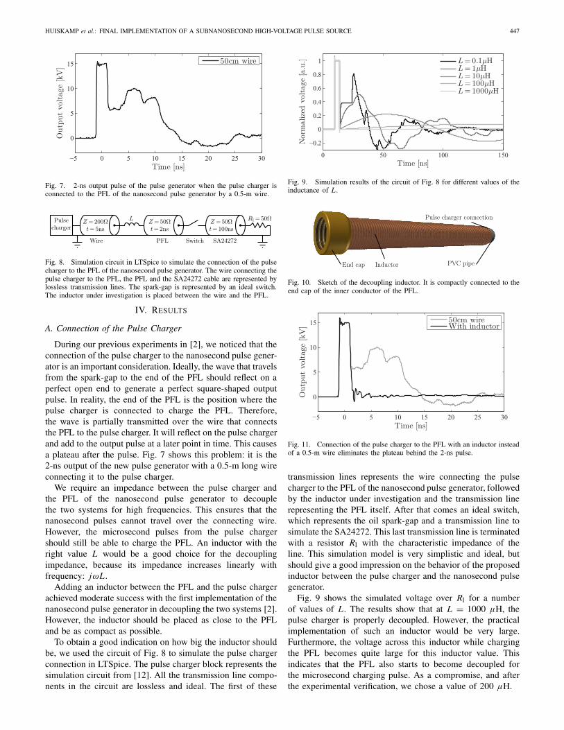
Fig. 7. 2-ns output pulse of the pulse generator when the pulse charger isconnected to the PFL of the nanosecond pulse generator by a 0.5-m wire.
Fig. 8. Simulation circuit in LTSpice to simulate the connection of the pulsecharger to the PFL of the nanosecond pulse generator. The wire connecting thepulse charger to the PFL, the PFL and the SA24272 cable are represented bylossless transmission lines. The spark-gap is represented by an ideal switch.The inductor under investigation is placed between the wire and the PFL.
IV. RESULTS
A. Connection of the Pulse Charger
During our previous experiments in [2], we noticed that theconnection of the pulse charger to the nanosecond pulse gener-ator is an important consideration. Ideally, the wave that travelsfrom the spark-gap to the end of the PFL should reflect on aperfect open end to generate a perfect square-shaped outputpulse. In reality, the end of the PFL is the position where thepulse charger is connected to charge the PFL. Therefore,the wave is partially transmitted over the wire that connectsthe PFL to the pulse charger. It will reflect on the pulse chargerand add to the output pulse at a later point in time. This causesa plateau after the pulse. Fig. 7 shows this problem: it is the2-ns output of the new pulse generator with a 0.5-m long wireconnecting it to the pulse charger.
We require an impedance between the pulse charger andthe PFL of the nanosecond pulse generator to decouplethe two systems for high frequencies. This ensures that thenanosecond pulses cannot travel over the connecting wire.However, the microsecond pulses from the pulse chargershould still be able to charge the PFL. An inductor with theright value L would be a good choice for the decouplingimpedance, because its impedance increases linearly withfrequency: jωL.
Adding an inductor between the PFL and the pulse chargerachieved moderate success with the first implementation of thenanosecond pulse generator in decoupling the two systems [2].However, the inductor should be placed as close to the PFLand be as compact as possible.
To obtain a good indication on how big the inductor shouldbe, we used the circuit of Fig. 8 to simulate the pulse chargerconnection in LTSpice. The pulse charger block represents thesimulation circuit from [12]. All the transmission line compo-nents in the circuit are lossless and ideal. The first of these
Fig. 9. Simulation results of the circuit of Fig. 8 for different values of theinductance of L .
Fig. 10. Sketch of the decoupling inductor. It is compactly connected to theend cap of the inner conductor of the PFL.
Fig. 11. Connection of the pulse charger to the PFL with an inductor insteadof a 0.5-m wire eliminates the plateau behind the 2-ns pulse.
transmission lines represents the wire connecting the pulsecharger to the PFL of the nanosecond pulse generator, followedby the inductor under investigation and the transmission linerepresenting the PFL itself. After that comes an ideal switch,which represents the oil spark-gap and a transmission line tosimulate the SA24272. This last transmission line is terminatedwith a resistor Rl with the characteristic impedance of theline. This simulation model is very simplistic and ideal, butshould give a good impression on the behavior of the proposedinductor between the pulse charger and the nanosecond pulsegenerator.
Fig. 9 shows the simulated voltage over Rl for a numberof values of L. The results show that at L = 1000 μH, thepulse charger is properly decoupled. However, the practicalimplementation of such an inductor would be very large.Furthermore, the voltage across this inductor while chargingthe PFL becomes quite large for this inductor value. Thisindicates that the PFL also starts to become decoupled forthe microsecond charging pulse. As a compromise, and afterthe experimental verification, we chose a value of 200 μH.
448 IEEE TRANSACTIONS ON PLASMA SCIENCE, VOL. 43, NO. 1, JANUARY 2015
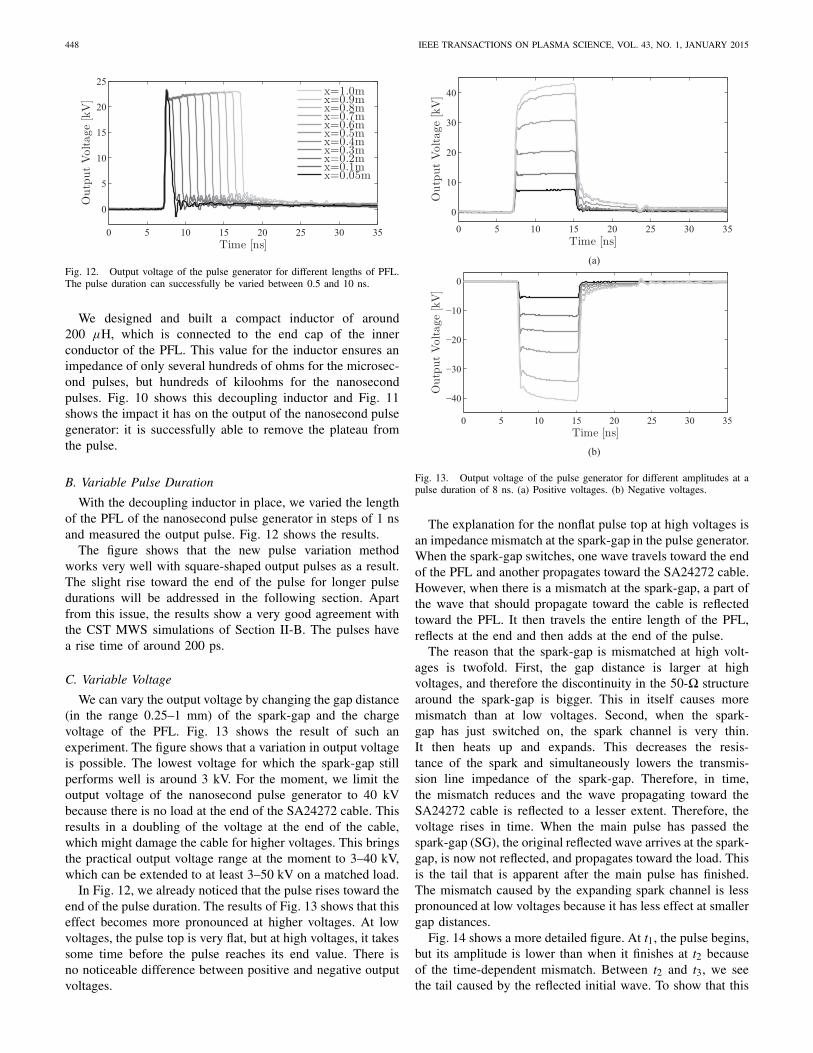
Fig. 12. Output voltage of the pulse generator for different lengths of PFL.The pulse duration can successfully be varied between 0.5 and 10 ns.
We designed and built a compact inductor of around200 μH, which is connected to the end cap of the innerconductor of the PFL. This value for the inductor ensures animpedance of only several hundreds of ohms for the microsec-ond pulses, but hundreds of kiloohms for the nanosecondpulses. Fig. 10 shows this decoupling inductor and Fig. 11shows the impact it has on the output of the nanosecond pulsegenerator: it is successfully able to remove the plateau fromthe pulse.
B. Variable Pulse Duration
With the decoupling inductor in place, we varied the lengthof the PFL of the nanosecond pulse generator in steps of 1 nsand measured the output pulse. Fig. 12 shows the results.
The figure shows that the new pulse variation methodworks very well with square-shaped output pulses as a result.The slight rise toward the end of the pulse for longer pulsedurations will be addressed in the following section. Apartfrom this issue, the results show a very good agreement withthe CST MWS simulations of Section II-B. The pulses havea rise time of around 200 ps.
C. Variable Voltage
We can vary the output voltage by changing the gap distance(in the range 0.25–1 mm) of the spark-gap and the chargevoltage of the PFL. Fig. 13 shows the result of such anexperiment. The figure shows that a variation in output voltageis possible. The lowest voltage for which the spark-gap stillperforms well is around 3 kV. For the moment, we limit theoutput voltage of the nanosecond pulse generator to 40 kVbecause there is no load at the end of the SA24272 cable. Thisresults in a doubling of the voltage at the end of the cable,which might damage the cable for higher voltages. This bringsthe practical output voltage range at the moment to 3–40 kV,which can be extended to at least 3–50 kV on a matched load.
In Fig. 12, we already noticed that the pulse rises toward theend of the pulse duration. The results of Fig. 13 shows that thiseffect becomes more pronounced at higher voltages. At lowvoltages, the pulse top is very flat, but at high voltages, it takessome time before the pulse reaches its end value. There isno noticeable difference between positive and negative outputvoltages.
Fig. 13. Output voltage of the pulse generator for different amplitudes at apulse duration of 8 ns. (a) Positive voltages. (b) Negative voltages.
The explanation for the nonflat pulse top at high voltages isan impedance mismatch at the spark-gap in the pulse generator.When the spark-gap switches, one wave travels toward the endof the PFL and another propagates toward the SA24272 cable.However, when there is a mismatch at the spark-gap, a part ofthe wave that should propagate toward the cable is reflectedtoward the PFL. It then travels the entire length of the PFL,reflects at the end and then adds at the end of the pulse.
The reason that the spark-gap is mismatched at high volt-ages is twofold. First, the gap distance is larger at highvoltages, and therefore the discontinuity in the 50-� structurearound the spark-gap is bigger. This in itself causes moremismatch than at low voltages. Second, when the spark-gap has just switched on, the spark channel is very thin.It then heats up and expands. This decreases the resis-tance of the spark and simultaneously lowers the transmis-sion line impedance of the spark-gap. Therefore, in time,the mismatch reduces and the wave propagating toward theSA24272 cable is reflected to a lesser extent. Therefore, thevoltage rises in time. When the main pulse has passed thespark-gap (SG), the original reflected wave arrives at the spark-gap, is now not reflected, and propagates toward the load. Thisis the tail that is apparent after the main pulse has finished.The mismatch caused by the expanding spark channel is lesspronounced at low voltages because it has less effect at smallergap distances.
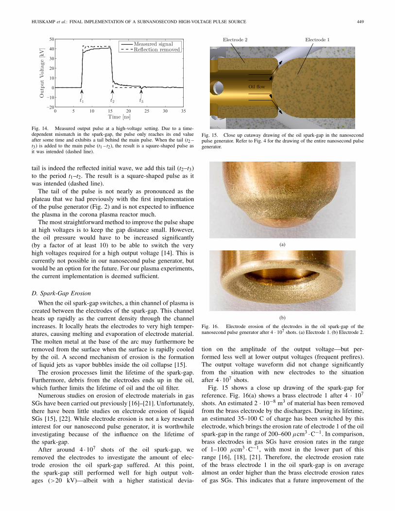
Fig. 14 shows a more detailed figure. At t1, the pulse begins,but its amplitude is lower than when it finishes at t2 becauseof the time-dependent mismatch. Between t2 and t3, we seethe tail caused by the reflected initial wave. To show that this
HUISKAMP et al.: FINAL IMPLEMENTATION OF A SUBNANOSECOND HIGH-VOLTAGE PULSE SOURCE 449
Fig. 14. Measured output pulse at a high-voltage setting. Due to a time-dependent mismatch in the spark-gap, the pulse only reaches its end valueafter some time and exhibits a tail behind the main pulse. When the tail (t2 –t3) is added to the main pulse (t1 – t2), the result is a square-shaped pulse asit was intended (dashed line).
tail is indeed the reflected initial wave, we add this tail (t2–t3)to the period t1–t2. The result is a square-shaped pulse as itwas intended (dashed line).
The tail of the pulse is not nearly as pronounced as theplateau that we had previously with the first implementationof the pulse generator (Fig. 2) and is not expected to influencethe plasma in the corona plasma reactor much.
The most straightforward method to improve the pulse shapeat high voltages is to keep the gap distance small. However,the oil pressure would have to be increased significantly(by a factor of at least 10) to be able to switch the veryhigh voltages required for a high output voltage [14]. This iscurrently not possible in our nanosecond pulse generator, butwould be an option for the future. For our plasma experiments,the current implementation is deemed sufficient.
D. Spark-Gap Erosion
When the oil spark-gap switches, a thin channel of plasma iscreated between the electrodes of the spark-gap. This channelheats up rapidly as the current density through the channelincreases. It locally heats the electrodes to very high temper-atures, causing melting and evaporation of electrode material.The molten metal at the base of the arc may furthermore beremoved from the surface when the surface is rapidly cooledby the oil. A second mechanism of erosion is the formationof liquid jets as vapor bubbles inside the oil collapse [15].
The erosion processes limit the lifetime of the spark-gap.Furthermore, debris from the electrodes ends up in the oil,which further limits the lifetime of oil and the oil filter.
Numerous studies on erosion of electrode materials in gasSGs have been carried out previously [16]–[21]. Unfortunately,there have been little studies on electrode erosion of liquidSGs [15], [22]. While electrode erosion is not a key researchinterest for our nanosecond pulse generator, it is worthwhileinvestigating because of the influence on the lifetime ofthe spark-gap.
After around 4 ·107 shots of the oil spark-gap, weremoved the electrodes to investigate the amount of elec-trode erosion the oil spark-gap suffered. At this point,the spark-gap still performed well for high output volt-ages (>20 kV)—albeit with a higher statistical devia-
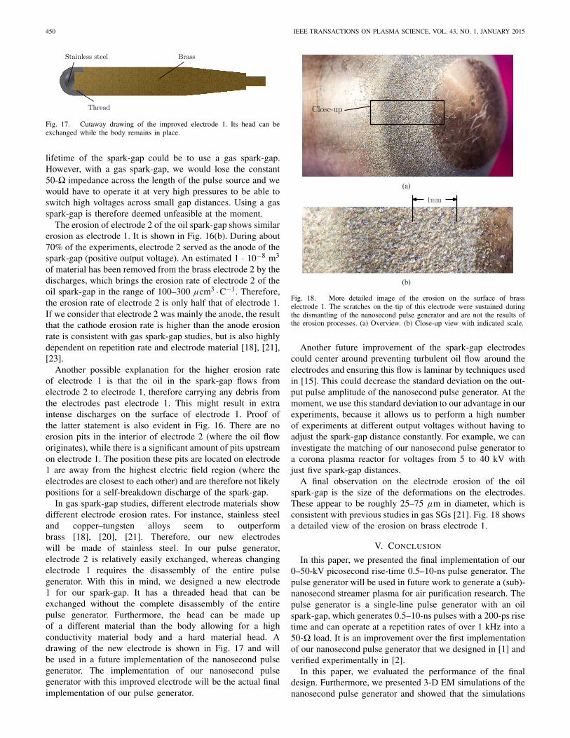
Fig. 15. Close up cutaway drawing of the oil spark-gap in the nanosecondpulse generator. Refer to Fig. 4 for the drawing of the entire nanosecond pulsegenerator.
Fig. 16. Electrode erosion of the electrodes in the oil spark-gap of thenanosecond pulse generator after 4 · 107 shots. (a) Electrode 1. (b) Electrode 2.
tion on the amplitude of the output voltage—but per-formed less well at lower output voltages (frequent prefires).The output voltage waveform did not change significantlyfrom the situation with new electrodes to the situationafter 4 ·107 shots.
Fig. 15 shows a close up drawing of the spark-gap forreference. Fig. 16(a) shows a brass electrode 1 after 4 · 107
shots. An estimated 2 · 10−8 m3 of material has been removedfrom the brass electrode by the discharges. During its lifetime,an estimated 35–100 C of charge has been switched by thiselectrode, which brings the erosion rate of electrode 1 of the oilspark-gap in the range of 200–600 μcm3 ·C−1. In comparison,brass electrodes in gas SGs have erosion rates in the rangeof 1–100 μcm3 ·C−1, with most in the lower part of thisrange [16], [18], [21]. Therefore, the electrode erosion rateof the brass electrode 1 in the oil spark-gap is on averagealmost an order higher than the brass electrode erosion ratesof gas SGs. This indicates that a future improvement of the
450 IEEE TRANSACTIONS ON PLASMA SCIENCE, VOL. 43, NO. 1, JANUARY 2015
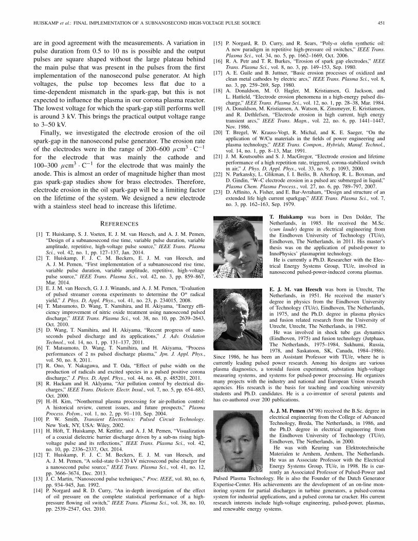
Fig. 17. Cutaway drawing of the improved electrode 1. Its head can beexchanged while the body remains in place.
lifetime of the spark-gap could be to use a gas spark-gap.However, with a gas spark-gap, we would lose the constant50-� impedance across the length of the pulse source and wewould have to operate it at very high pressures to be able toswitch high voltages across small gap distances. Using a gasspark-gap is therefore deemed unfeasible at the moment.
The erosion of electrode 2 of the oil spark-gap shows similarerosion as electrode 1. It is shown in Fig. 16(b). During about70% of the experiments, electrode 2 served as the anode of thespark-gap (positive output voltage). An estimated 1 · 10−8 m3
of material has been removed from the brass electrode 2 by thedischarges, which brings the erosion rate of electrode 2 of theoil spark-gap in the range of 100–300 μcm3 ·C−1. Therefore,the erosion rate of electrode 2 is only half that of electrode 1.If we consider that electrode 2 was mainly the anode, the resultthat the cathode erosion rate is higher than the anode erosionrate is consistent with gas spark-gap studies, but is also highlydependent on repetition rate and electrode material [18], [21],[23].
Another possible explanation for the higher erosion rateof electrode 1 is that the oil in the spark-gap flows fromelectrode 2 to electrode 1, therefore carrying any debris fromthe electrodes past electrode 1. This might result in extraintense discharges on the surface of electrode 1. Proof ofthe latter statement is also evident in Fig. 16. There are noerosion pits in the interior of electrode 2 (where the oil floworiginates), while there is a significant amount of pits upstreamon electrode 1. The position these pits are located on electrode1 are away from the highest electric field region (where theelectrodes are closest to each other) and are therefore not likelypositions for a self-breakdown discharge of the spark-gap.
In gas spark-gap studies, different electrode materials showdifferent electrode erosion rates. For instance, stainless steeland copper–tungsten alloys seem to outperformbrass [18], [20], [21]. Therefore, our new electrodeswill be made of stainless steel. In our pulse generator,electrode 2 is relatively easily exchanged, whereas changingelectrode 1 requires the disassembly of the entire pulsegenerator. With this in mind, we designed a new electrode1 for our spark-gap. It has a threaded head that can beexchanged without the complete disassembly of the entirepulse generator. Furthermore, the head can be made upof a different material than the body allowing for a highconductivity material body and a hard material head. Adrawing of the new electrode is shown in Fig. 17 and willbe used in a future implementation of the nanosecond pulsegenerator. The implementation of our nanosecond pulsegenerator with this improved electrode will be the actual finalimplementation of our pulse generator.
Fig. 18. More detailed image of the erosion on the surface of brasselectrode 1. The scratches on the tip of this electrode were sustained duringthe dismantling of the nanosecond pulse generator and are not the results ofthe erosion processes. (a) Overview. (b) Close-up view with indicated scale.
Another future improvement of the spark-gap electrodescould center around preventing turbulent oil flow around theelectrodes and ensuring this flow is laminar by techniques usedin [15]. This could decrease the standard deviation on the out-put pulse amplitude of the nanosecond pulse generator. At themoment, we use this standard deviation to our advantage in ourexperiments, because it allows us to perform a high numberof experiments at different output voltages without having toadjust the spark-gap distance constantly. For example, we caninvestigate the matching of our nanosecond pulse generator toa corona plasma reactor for voltages from 5 to 40 kV withjust five spark-gap distances.
A final observation on the electrode erosion of the oilspark-gap is the size of the deformations on the electrodes.These appear to be roughly 25–75 μm in diameter, which isconsistent with previous studies in gas SGs [21]. Fig. 18 showsa detailed view of the erosion on brass electrode 1.
V. CONCLUSION
In this paper, we presented the final implementation of our0–50-kV picosecond rise-time 0.5–10-ns pulse generator. Thepulse generator will be used in future work to generate a (sub)-nanosecond streamer plasma for air purification research. Thepulse generator is a single-line pulse generator with an oilspark-gap, which generates 0.5–10-ns pulses with a 200-ps risetime and can operate at a repetition rates of over 1 kHz into a50-� load. It is an improvement over the first implementationof our nanosecond pulse generator that we designed in [1] andverified experimentally in [2].
In this paper, we evaluated the performance of the finaldesign. Furthermore, we presented 3-D EM simulations of thenanosecond pulse generator and showed that the simulations
HUISKAMP et al.: FINAL IMPLEMENTATION OF A SUBNANOSECOND HIGH-VOLTAGE PULSE SOURCE 451
are in good agreement with the measurements. A variation inpulse duration from 0.5 to 10 ns is possible and the outputpulses are square shaped without the large plateau behindthe main pulse that was present in the pulses from the firstimplementation of the nanosecond pulse generator. At highvoltages, the pulse top becomes less flat due to atime-dependent mismatch in the spark-gap, but this is notexpected to influence the plasma in our corona plasma reactor.The lowest voltage for which the spark-gap still performs wellis around 3 kV. This brings the practical output voltage rangeto 3–50 kV.
Finally, we investigated the electrode erosion of the oilspark-gap in the nanosecond pulse generator. The erosion rateof the electrodes were in the range of 200–600 μcm3 · C−1
for the electrode that was mainly the cathode and100–300 μcm3 · C−1 for the electrode that was mainly theanode. This is almost an order of magnitude higher than mostgas spark-gap studies show for brass electrodes. Therefore,electrode erosion in the oil spark-gap will be a limiting factoron the lifetime of the system. We designed a new electrodewith a stainless steel head to increase this lifetime.
REFERENCES
[1] T. Huiskamp, S. J. Voeten, E. J. M. van Heesch, and A. J. M. Pemen,“Design of a subnanosecond rise time, variable pulse duration, variableamplitude, repetitive, high-voltage pulse source,” IEEE Trans. PlasmaSci., vol. 42, no. 1, pp. 127–137, Jan. 2014.
[2] T. Huiskamp, F. J. C. M. Beckers, E. J. M. van Heesch, andA. J. M. Pemen, “First implementation of a subnanosecond rise time,variable pulse duration, variable amplitude, repetitive, high-voltagepulse source,” IEEE Trans. Plasma Sci., vol. 42, no. 3, pp. 859–867,Mar. 2014.
[3] E. J. M. van Heesch, G. J. J. Winands, and A. J. M. Pemen, “Evaluationof pulsed streamer corona experiments to determine the O* radicalyield,” J. Phys. D, Appl. Phys., vol. 41, no. 23, p. 234015, 2008.
[4] T. Matsumoto, D. Wang, T. Namihira, and H. Akiyama, “Energy effi-ciency improvement of nitric oxide treatment using nanosecond pulseddischarge,” IEEE Trans. Plasma Sci., vol. 38, no. 10, pp. 2639–2643,Oct. 2010.
[5] D. Wang, T. Namihira, and H. Akiyama, “Recent progress of nano-seconds pulsed discharge and its applications,” J. Adv. OxidationTechnol., vol. 14, no. 1, pp. 131–137, 2011.
[6] T. Matsumoto, D. Wang, T. Namihira, and H. Akiyama, “Processperformances of 2 ns pulsed discharge plasma,” Jpn. J. Appl. Phys.,vol. 50, no. 8, 2011.
[7] R. Ono, Y. Nakagawa, and T. Oda, “Effect of pulse width on theproduction of radicals and excited species in a pulsed positive coronadischarge,” J. Phys. D, Appl. Phys., vol. 44, no. 48, p. 485201, 2011.
[8] R. Hackam and H. Aklyama, “Air pollution control by electrical dis-charges,” IEEE Trans. Dielectr. Electr. Insul., vol. 7, no. 5, pp. 654–683,Oct. 2000.
[9] H.-H. Kim, “Nonthermal plasma processing for air-pollution control:A historical review, current issues, and future prospects,” PlasmaProcess. Polym., vol. 1, no. 2, pp. 91–110, Sep. 2004.
[10] P. W. Smith, Transient Electronics: Pulsed Circuit Technology.New York, NY, USA: Wiley, 2002.
[11] H. Höft, T. Huiskamp, M. Kettlitz, and A. J. M. Pemen, “Visualizationof a coaxial dielectric barrier discharge driven by a sub-ns rising high-voltage pulse and its reflections,” IEEE Trans. Plasma Sci., vol. 42,no. 10, pp. 2336–2337, Oct. 2014.
[12] T. Huiskamp, F. J. C. M. Beckers, E. J. M. van Heesch, andA. J. M. Pemen, “A solid-state 0–120 kV microsecond pulse charger fora nanosecond pulse source,” IEEE Trans. Plasma Sci., vol. 41, no. 12,pp. 3666–3674, Dec. 2013.
[13] J. C. Martin, “Nanosecond pulse techniques,” Proc. IEEE, vol. 80, no. 6,pp. 934–945, Jun. 1992.
[14] P. Norgard and R. D. Curry, “An in-depth investigation of the effectof oil pressure on the complete statistical performance of a high-pressure flowing oil switch,” IEEE Trans. Plasma Sci., vol. 38, no. 10,pp. 2539–2547, Oct. 2010.
[15] P. Norgard, R. D. Curry, and R. Sears, “Poly-α olefin synthetic oil:A new paradigm in repetitive high-pressure oil switches,” IEEE Trans.Plasma Sci., vol. 34, no. 5, pp. 1662–1669, Oct. 2006.
[16] R. A. Petr and T. R. Burkes, “Erosion of spark gap electrodes,” IEEETrans. Plasma Sci., vol. 8, no. 3, pp. 149–153, Sep. 1980.
[17] A. E. Guile and B. Juttner, “Basic erosion processes of oxidized andclean metal cathodes by electric arcs,” IEEE Trans. Plasma Sci., vol. 8,no. 3, pp. 259–269, Sep. 1980.
[18] A. Donaldson, M. O. Hagler, M. Kristiansen, G. Jackson, andL. Hatfield, “Electrode erosion phenomena in a high-energy pulsed dis-charge,” IEEE Trans. Plasma Sci., vol. 12, no. 1, pp. 28–38, Mar. 1984.
[19] A. Donaldson, M. Kristiansen, A. Watson, K. Zinsmeyer, E. Kristiansen,and R. Dethlefsen, “Electrode erosion in high current, high energytransient arcs,” IEEE Trans. Magn., vol. 22, no. 6, pp. 1441–1447,Nov. 1986.
[20] T. Bregel, W. Krauss-Vogt, R. Michal, and K. E. Saeger, “On theapplication of W/Cu materials in the fields of power engineering andplasma technology,” IEEE Trans. Compon., Hybrids, Manuf. Technol.,vol. 14, no. 1, pp. 8–13, Mar. 1991.
[21] J. M. Koutsoubis and S. J. MacGregor, “Electrode erosion and lifetimeperformance of a high repetition rate, triggered, corona-stabilized switchin air,” J. Phys. D, Appl. Phys., vol. 33, no. 9, p. 1093, 2000.
[22] N. Parkansky, L. Glikman, I. I. Beilis, B. Alterkop, R. L. Boxman, andD. Gindin, “W–C electrode erosion in a pulsed arc submerged in liquid,”Plasma Chem. Plasma Process., vol. 27, no. 6, pp. 789–797, 2007.
[23] D. Affinito, A. Fisher, and E. Bar-Avraham, “Design and structure of anextended life high current sparkgap,” IEEE Trans. Plasma Sci., vol. 7,no. 3, pp. 162–163, Sep. 1979.
T. Huiskamp was born in Den Dolder, TheNetherlands, in 1985. He received the M.Sc.(cum laude) degree in electrical engineering fromthe Eindhoven University of Technology (TU/e),Eindhoven, The Netherlands, in 2011. His master’sthesis was on the application of pulsed-power toInnoPhysics’ plasmaprint technology.
He is currently a Ph.D. Researcher with the Elec-trical Energy Systems Group, TU/e, involved innanosecond pulsed-power-induced corona plasmas.
E. J. M. van Heesch was born in Utrecht, TheNetherlands, in 1951. He received the master’sdegree in physics from the Eindhoven Universityof Technology (TU/e), Eindhoven, The Netherlands,in 1975, and the Ph.D. degree in plasma physicsand fusion related research from the University ofUtrecht, Utrecht, The Netherlands, in 1982.
He was involved in shock tube gas dynamics(Eindhoven, 1975) and fusion technology (Jutphaas,The Netherlands, 1975–1984, Sukhumi, Russia,1978, and Saskatoon, SK, Canada, 1984–1986).
Since 1986, he has been an Assistant Professor with TU/e, where he iscurrently leading pulsed power research. Among his designs are variousplasma diagnostics, a toroidal fusion experiment, substation high-voltagemeasuring systems, and systems for pulsed-power processing. He organizesmany projects with the industry and national and European Union researchagencies. His research is the basis for teaching and coaching universitystudents and Ph.D. candidates. He is a co-inventor of several patents andhas co-authored over 200 publications.
A. J. M. Pemen (M’98) received the B.Sc. degree inelectrical engineering from the College of AdvancedTechnology, Breda, The Netherlands, in 1986, andthe Ph.D. degree in electrical engineering fromthe Eindhoven University of Technology (TU/e),Eindhoven, The Netherlands, in 2000.
He was with Keuring van ElektrotechnischeMaterialen te Arnhem, Arnhem, The Netherlands.He was an Associate Professor with the ElectricalEnergy Systems Group, TU/e, in 1998. He is cur-rently an Associated Professor of Pulsed-Power and
Pulsed Plasma Technology. He is also the Founder of the Dutch GeneratorExpertise-Center. His achievements are the development of an on-line mon-itoring system for partial discharges in turbine generators, a pulsed-coronasystem for industrial applications, and a pulsed corona tar cracker. His currentresearch interests include high-voltage engineering, pulsed-power, plasmas,and renewable energy systems.