Embed Size (px)
Citation preview

Arithmetic
A basic operation in all digital computers is the addition and subtraction of two numbers
They are implemented, along with the basic logic functions such as AND,OR, NOT,EX-
OR in the ALU subsystem of the processor. In this chapter we will study how to
implement these operations by using different techniques.
Addition and Subtraction of Signed Numbers
Half Adder
Figure 1(a),(b),(c),(d): Implementation of Half Adder
Full Adder
The following figure 2 shows the logic truth table for the sum and carry-out functions for
adding equally weighted bits xi and yi in two numbers X and Y. The figure also shows
logic expressions for these functions, along with an example of addition of the 4-bit
unsigned numbers 7 and 6.
Sum
s
0
1
1
0
Carry
c
0
0
0
1
0
0 +
0
1 +
1 0 0 0
1
0 +
1 0
1
1 +
0 1
x
y +
s c
Sum Carry
(a) The four possible cases
x y
0
0
1
1
0
1
0
1
(b) Truth table
x
y s
c
HAx
y
s
c
(c) Circuit (d) Graphical symbol
www.alls
yllab
us.co
m
vtu.allsyllabus.com www.allsyllabus.com
www.allsyllabus.com
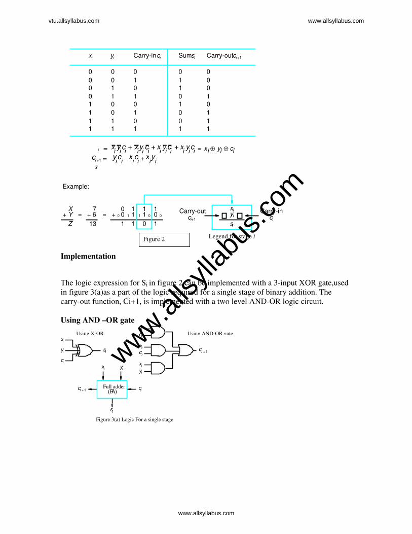
Implementation
The logic expression for Si in figure 2 can be implemented with a 3-input XOR gate,used
in figure 3(a)as a part of the logic required for a single stage of binary addition. The
carry-out function, Ci+1, is implemented with a two level AND-OR logic circuit.
Using AND –OR gate
Full adder(F A)
c i
y i x i
c i 1 +
s i
Figure 3(a) Logic For a single stage
c i
y i
x i c
i
y i x i
x i
c i y i s i c
i 1 +
Using X-OR Using AND-OR gate
s
i =c
i +1 =
13
7+ Y
1
0 0 0 1 0
1
1
0 0 1 1 0
1 1
0
0
1
1
0
1
0
0
1
0
0
0
0
1
1
1
1
0
0
0
0
1
1
1
1
Example:
10 = = 0 0
1 1 1
1 1 0 01
1 1 10
Legend for stage i
x i y i Carry-inc i Sums i Carry-outc i +1
X
Z + 6 0 +
x i y i s i
Carry-outc i +1
Carry-inc i
x i y i c i x
i y i c i x i y i c i x
i y i c i x i y i c i ⊕ ⊕=+ + +
y i c i x
i c i x i y i +
Figure 2
www.alls
yllab
us.co
m
vtu.allsyllabus.com www.allsyllabus.com
www.allsyllabus.com

A cascaded connection of n full adder blocks, as shown in figure 4(a), can be use to add
two n-bit numbers. Since the carries must propagate, or ripple through this cascade, the
configuration is called n-bit ripple carry adder.
Overflow – Overflow occurs in signed numbers having same signs, and sign of the result
is different, and also it is shown that carry bits Cn and C n-1 are different. A circuit is
added to detect overflow, eg. C n-1⊕ Cn
In order to perform the subtract operation X-Y on 2’s complement numbers X and Y, we
form the 2s-complement of Y and add it to X. The logic circuit network shown in figure
(5) can be used to perform either addition or subtraction based on the value applied to the
Add/Sub input control line. This line is set to 0 for addition, applying the Y vector un
changed to one of the adder inputs along with a carry-in signal,C0 of 0 . When Add/Sub
control line is set to 1, the Y vector is 1’s complemented by the XOR gates and C0 is set
to 1 to complete the 2’s complementation of Y. Remember that 2’s complementing a
negative number is done exactly same manner as for positive number. An XOR gate can
be added to Figure(5) to detect the overflow condition C n-1⊕ Cn
Add/Subcontrol
n -bit adder
x n 1- x1 x 0
c n
sn 1- s1 s0
c0
y n 1- y 1 y0
Figure 6.3. Binary addition-subtraction logic netw ork.
FA c 0
y 1x 1
s 1
FA
c 1
y 0x 0
s 0
FA c n 1-
y n 1- x n 1-
c n
s n 1-
Figure 4(a) An n-bit ripple carry adder
Most significant bit(MSB) position
Least significant bit (LSB) position
www.alls
yllab
us.co
m
vtu.allsyllabus.com www.allsyllabus.com
www.allsyllabus.com
Design of Fast Adders If an n-bit ripple carry adder is used in the addition /subtraction unit of Figure (3), it may
have too much delay in developing its outputs, s0 through sn-1 and c n. The delay through
any combinational logic network constructed from gates in a particular technology is
determined by adding up the number of logic gate delays along the longest signal
propagation path through the network. In the case of n-bit ripple-carry adder, the longest
path is from inputs x0,y0, and c0 at the LSB position to outputs cn and sn-1 at the most-
significant-bit(MSB) position.
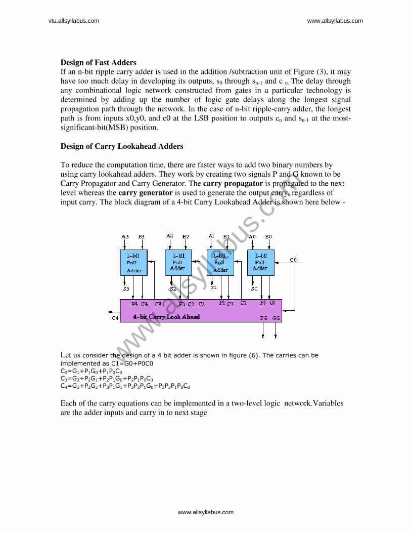
Design of Carry Lookahead Adders To reduce the computation time, there are faster ways to add two binary numbers by
using carry lookahead adders. They work by creating two signals P and G known to be
Carry Propagator and Carry Generator. The carry propagator is propagated to the next
level whereas the carry generator is used to generate the output carry, regardless of
input carry. The block diagram of a 4-bit Carry Lookahead Adder is shown here below -
Let us consider the design of a 4 bit adder is shown in figure (6). The carries can be implemented as C1=G0+P0C0
C2=G1+P1G0+P1P0C0
C3=G2+P2G1+P2P1G0+P2P1P0C0 C4=G3+P3G2+P3P1G1+P3P2P1G0+P3P2P1P0C0
Each of the carry equations can be implemented in a two-level logic network.Variables
are the adder inputs and carry in to next stage
www.alls
yllab
us.co
m
vtu.allsyllabus.com www.allsyllabus.com
www.allsyllabus.com
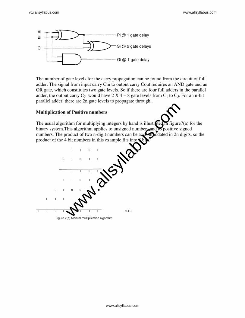
The number of gate levels for the carry propagation can be found from the circuit of full
adder. The signal from input carry Cin to output carry Cout requires an AND gate and an
OR gate, which constitutes two gate levels. So if there are four full adders in the parallel
adder, the output carry C5 would have 2 X 4 = 8 gate levels from C1 to C5. For an n-bit
parallel adder, there are 2n gate levels to propagate through..
Multiplication of Positive numbers
The usual algorithm for multiplying integers by hand is illustrated in figure7(a) for the
binary system.This algorithm applies to unsigned numbers and to positive signed
numbers. The product of two n-digit numbers can be accommodated in 2n digits, so the
product of the 4 bit numbers in this example fits into 8 bits.
(13) 1
1
(143)
(11) 1
0
0
1
1
1
1 1 0 1
1011
0000
1011
01 0 0 1 1 1 1
×
Figure 7(a) Manual multiplication algorithm
Pi @ 1 gate delay
Ci Si @ 2 gate delays
Bi
Ai
Gi @ 1 gate delay
www.alls
yllab
us.co
m
vtu.allsyllabus.com www.allsyllabus.com
www.allsyllabus.com
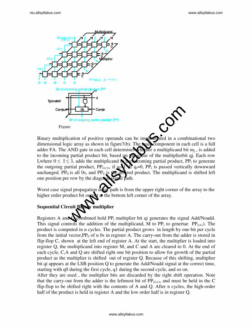
Binary multiplication of positive operands can be implemented in a combinational two
dimensional logic array as shown in figure7(b). The main component in each cell is a full
adder FA. The AND gate in each cell determines whether a multiplicand bit mj , is added
to the incoming partial product bit, based on the value of the multiplierbit qj. Each row
I,where 0 ≤ I ≤ 3, adds the multiplicand to the incoming partial product, PPi to generate
the outgoing partial product, PP(i+1), if qi=1. If qi=0, PPi is passed vertically downward
unchanged. PP0 is all 0s, and PP4 is the desired product. The multiplicand is shifted left
one position per row by the diagonal signal path.
Worst case signal propagation delay path is from the upper right corner of the array to the
higher order product bit output at the bottom left corner of the array.
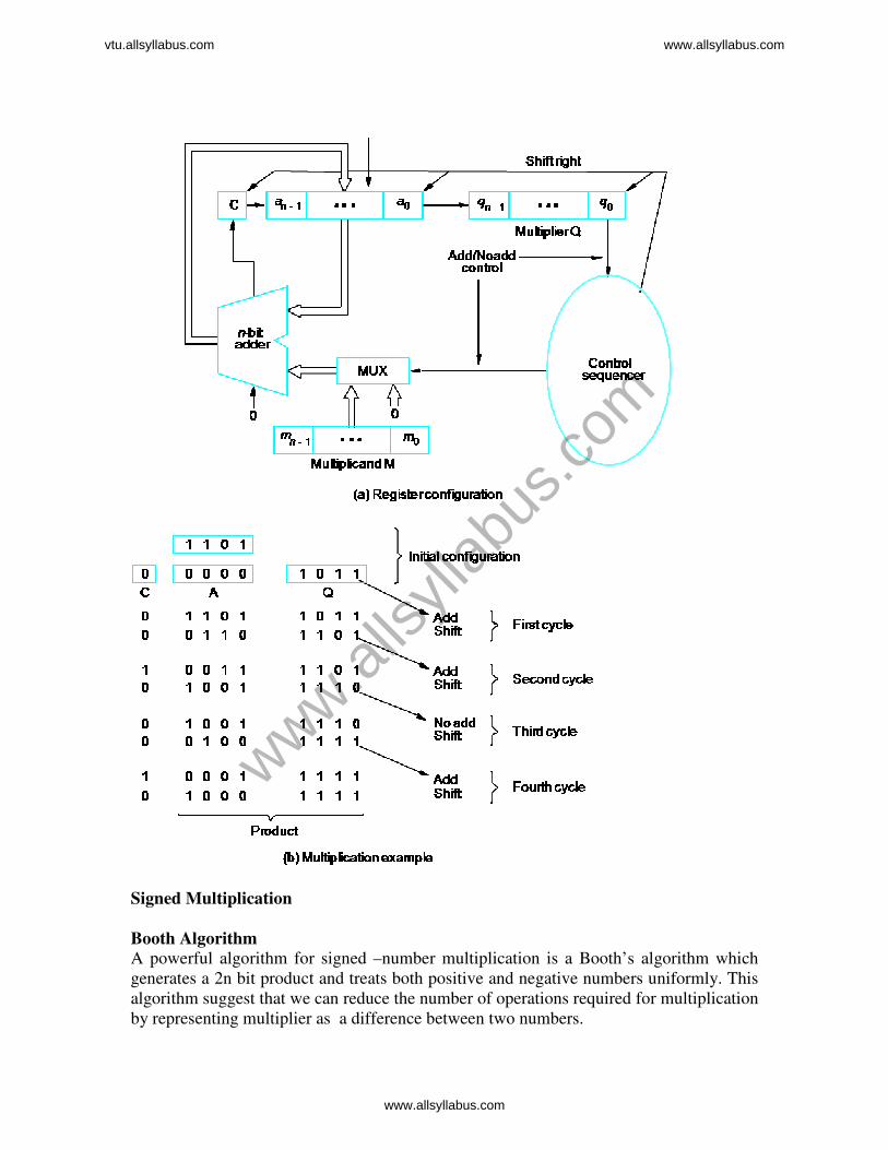
Sequential Circuit Binary multiplier
Registers A and Q combined hold PPi multiplier bit qi generates the signal Add/Noadd.
This signal controls the addition of the multiplicand, M to PPi to genertae PP(i+1). The
product is computed in n cycles. The partial product grows in length by one bit per cycle
from the initial vector,PP0 of n 0s in register A. The carry-out from the adder is stored in
flip-flop C, shown at the left end of register A. At the start, the multiplier is loaded into
register Q, the multiplicand into register M, and C and A are cleared to 0. At the end of
each cycle, C,A and Q are shifted right one bit position to allow for growth of the partial
product as the multiplier is shifted out of register Q. Because of this shifting, multiplier
bit qi appears at the LSB position Q to generate the Add/Noadd signal at the correct time,
starting with q0 during the first cycle, q1 during the second cycle, and so on.
After they are used , the multiplier bits are discarded by the right shift operation. Note
that the carry-out from the adder is the leftmost bit of PP(i+1), and must be held in the C
flip-flop to be shifted right with the contents of A and Q. After n cycles, the high-order
half of the product is held in register A and the low order half is in register Q.
Multiplier
Multiplicand
m3 m2 m1 m00 0 0 0
q3
q2
q1
q 0
p2
p1
p 0
0
0
0
p3 p4p5 p6 p7
Multiplier
Multiplicand
m3 m2 m1 m00 0 0 0
q3
q2
q1
q0 0
p2
p1
p 0
0
0
0
p3 p4p5 p6 p7
PP1
PP2
PP3
P artialproduct (PP0)
p,p, ...pPP4 = 7 6 0= Product
Carry- in
qi
mj Bit of incoming partial product (PPi )
Bit of outgoing partial product [PP( i +1)]
Carry-out
Typical cell
FA Carry- in
qi
mj Bit of incoming partial product (PPi )
Bit of outgoing partial product [PP( i +1)]
Carry-out
Typical cell
FA
Figure
www.alls
yllab
us.co
m
vtu.allsyllabus.com www.allsyllabus.com
www.allsyllabus.com
Signed Multiplication
Booth Algorithm A powerful algorithm for signed –number multiplication is a Booth’s algorithm which
generates a 2n bit product and treats both positive and negative numbers uniformly. This
algorithm suggest that we can reduce the number of operations required for multiplication
by representing multiplier as a difference between two numbers.
www.alls
yllab
us.co
m
vtu.allsyllabus.com www.allsyllabus.com
www.allsyllabus.com

For example, multiplier 0 0 1 1 1 0(14) can be represented as follows.
0 1 0 0 0 0 (16)
- 0 0 0 0 1 0 (2)
-----------------------
0 0 1 1 1 0 (14)
Therefore, the product can be computed by adding 24 times the multiplicand to the 2s
complement of 21 times the multiplicand. In simple notations, we can describe the
sequence of required operations be recoding the preceding multiplier as
0 + 1 0 0 -1 0
In general , For Booth’s algorithm recoding scheme can be given as
-1 times the shifted multiplicand is selected when moving from 0 to 1,+1 times the
shifted multiplicand is selected when moving from 1 to 0, and 0 timesw the shifted
muluiplicand is selected for none of the above case,as multiplier is scanned from right to
left.
Fast Multiplication -- Booth's Algorithm
The Booth's algorithm serves two purposes:
1. Fast multiplication (when there are consecutive 0's or 1's in the multiplier).
2. Signed multiplication.
First consider two decimal multiplications: and . It is obvious that If straight forward
multiplication is used, the first one is easier than the second as only two single-digit
multiplications are needed for the first while four are needed for the second. However, as
we also realize that:
the two multiplications should be equally easy.
Example 1
If there is a sequence of 0's in the multiplier, the multiplication is easy as all 0's can be
skipped.
www.alls
yllab
us.co
m
vtu.allsyllabus.com www.allsyllabus.com
www.allsyllabus.com
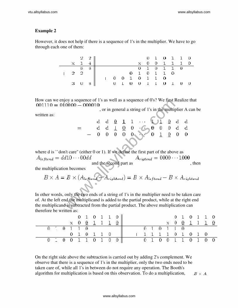
Example 2
However, it does not help if there is a sequence of 1's in the multiplier. We have to go
through each one of them:
How can we enjoy a sequence of 1's as well as a sequence of 0's? We first Realize that
, or in general a string of 1's in the multiplier A can be
written as:
where d is ``don't care'' (either 0 or 1). If we define the first part of the above as
and the second part as , then
the multiplication becomes
In other words, only the two ends of a string of 1's in the multiplier need to be taken care
of. At the left end the multiplicand is added to the partial product, while at the right end
the multiplicand is subtracted from the partial product. The above multiplication can
therefore be written as:
On the right side above the subtraction is carried out by adding 2's complement. We
observe that there is a sequence of 1's in the multiplier, only the two ends need to be
taken care of, while all 1's in between do not require any operation. The Booth's
algorithm for multiplication is based on this observation. To do a multiplication,
www.alls
yllab
us.co
m
vtu.allsyllabus.com www.allsyllabus.com
www.allsyllabus.com

where
• is the multiplicand
• is the multiplier
we check every two consecutive bits in at a time:
where , and when , .
Why does it work? What we did can be summarized as the following
* Recall that the value of a signed-2's complement number (either positive or negative)
can be found by:
www.alls
yllab
us.co
m
vtu.allsyllabus.com www.allsyllabus.com
www.allsyllabus.com

Another Example:
Assume bits available. Multiply by
. First represent both operands and their negation in
signed 2's complement:
Then carry out the multiplication in the hardware:
The upper half of the final result is in register [A] while the lower
half is in register [Q]. The product is given in signed 2's complement and its actual value
is negative of the 2's complement:
www.alls
yllab
us.co
m
vtu.allsyllabus.com www.allsyllabus.com
www.allsyllabus.com
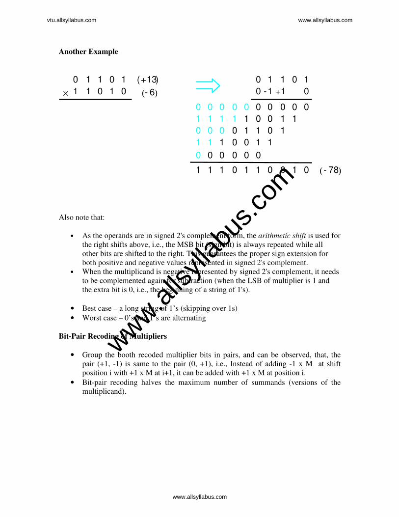
Another Example
Also note that:
• As the operands are in signed 2's complement form, the arithmetic shift is used for
the right shifts above, i.e., the MSB bit (sign bit) is always repeated while all
other bits are shifted to the right. This guarantees the proper sign extension for
both positive and negative values represented in signed 2's complement.
• When the multiplicand is negative represented by signed 2's complement, it needs
to be complemented again for subtraction (when the LSB of multiplier is 1 and
the extra bit is 0, i.e., the beginning of a string of 1's).
• Best case – a long string of 1’s (skipping over 1s)
• Worst case – 0’s and 1’s are alternating
Bit-Pair Recoding of Multipliers
• Group the booth recoded multiplier bits in pairs, and can be observed, that, the
pair (+1, -1) is same to the pair (0, +1), i.e., Instead of adding -1 x M at shift
position i with +1 x M at i+1, it can be added with +1 x M at position i.
• Bit-pair recoding halves the maximum number of summands (versions of the
multiplicand).
01
0
1 1 1 1 0 1 1
0 0 0 0 0 0 0 0 0
00
0110
0 0 0 0 1 1 0
1100111
0 0 0 0 0 0
01000 11111
1
10 1 1 0 1 1 1 0 1 0 6- ( )
13+ ( )
×
78- ( )
+1 1-
www.alls
yllab
us.co
m
vtu.allsyllabus.com www.allsyllabus.com
www.allsyllabus.com

Example
i 1+ i 1
(b) Table of multiplicand selection decisions
selected at position i
Multiplicand Multiplier bit-pair
i
0
0 1
1
1 0 1 0
1
1
1
1
0
0
0
1
1
0
0
1
0
0
1
Multiplier bit on the right
0 0 M×
1+ M×
1 M×
1+ M×
0 M×
1 M×
2 M×
2+ M×
−
−
−
1 +1 −
0
0 0 0
1 1 0 1 0 Implied 0 to right of LSB
1
0
Sign extension
1
2 1− −
www.alls
yllab
us.co
m
vtu.allsyllabus.com www.allsyllabus.com
www.allsyllabus.com
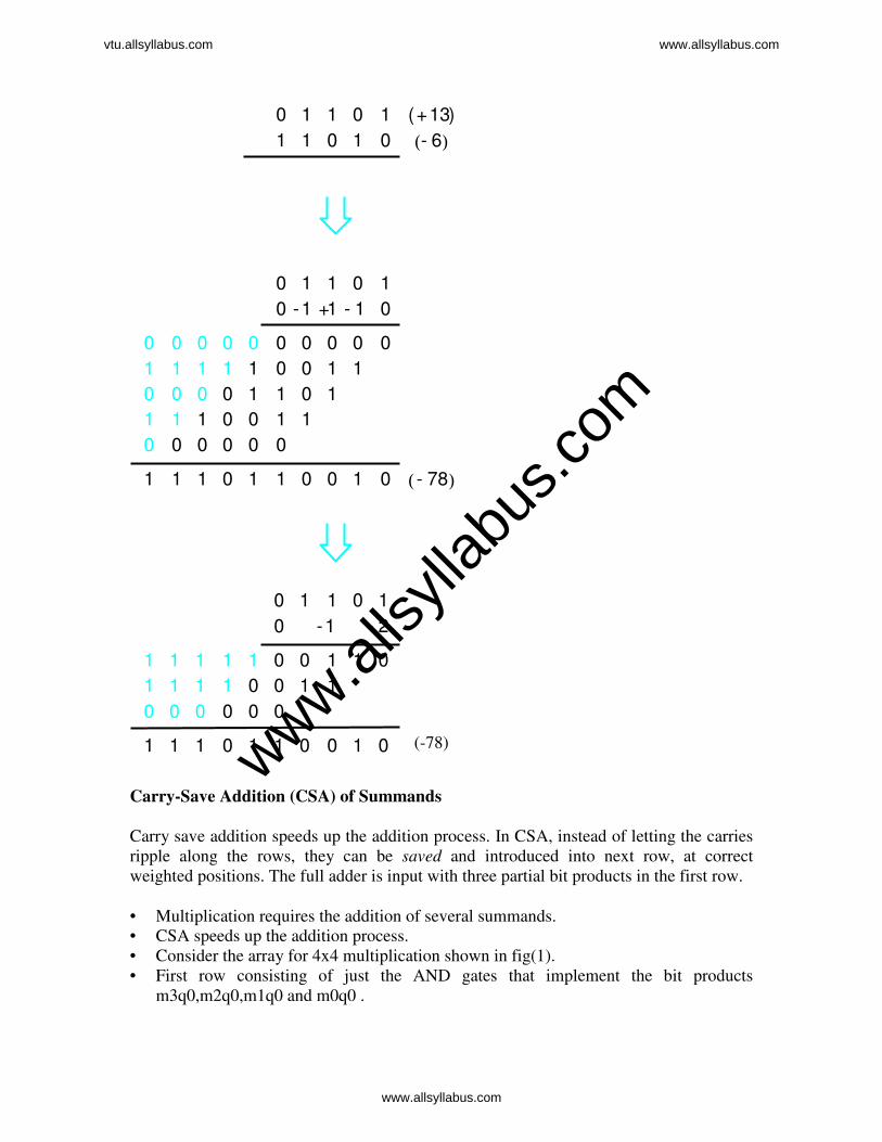
Carry-Save Addition (CSA) of Summands
Carry save addition speeds up the addition process. In CSA, instead of letting the carries
ripple along the rows, they can be saved and introduced into next row, at correct
weighted positions. The full adder is input with three partial bit products in the first row.
• Multiplication requires the addition of several summands.
• CSA speeds up the addition process.
• Consider the array for 4x4 multiplication shown in fig(1).
• First row consisting of just the AND gates that implement the bit products
m3q0,m2q0,m1q0 and m0q0 .
1 -
0 000
1 1 1 1 1 0 0 0 0 0 1 1
1 1 1 1 1 0 0
0 0 0 0 0 0 000 0 11 1111
0 1 1 0 1
0
1 010011 11 1
1 1 1 1 0 0 1 1
0 0 0 0 0 0
1 1 1 0 1 1 0 0 1 0
0
1
0 0
1 0
1
0 0
0
0 1
0
0 1
10
0
010
0 1 1 0 1
1 1
1 -
6 -( ) 13+ ( )
1+
78- ( )
1- 2-
(-78) www.alls
yllab
us.co
m
vtu.allsyllabus.com www.allsyllabus.com
www.allsyllabus.com

F A F A F AF A
F A F A F AF A
F A F A F AF A
p7 p6 p5 p4 p3 p1 p0p2
0 m 3q0
m3q 1
(a) Ripple-c arry a rray (Figure 6.6 s t ructure)
m2q1
m2 q0 m1q0
m1q1 m 0q1
m 3q2 m2q 2 m1q2 m0q2
m3q3 m2q3 m1 q3 m0q3
0
0
0
m0 q0
• The delay through the carry-save array is somewhat less than delay through the
ripple-carry array. This is because the S and C vector outputs from each row are
produced in parallel in one full-adder delay.
• Consider the addition of many summands, we can:
• Group the summands in threes and perform carry-save addition on each of these
groups in parallel to generate a set of S and C vectors in one full-adder delay
• Group all of the S and C vectors into threes, and perform carry-save addition on
them, generating a further set of S and C vectors in one more full-adder delay
• Continue with this process until there are only two vectors remaining
FA FA FAFA
FA FA FAFA
FA FA FAFA
p7 p6 p5 p4 p3 p1 p0p2
0 m3q0
m3q1
(b) Carry-save array
m2q1
m2q0 m1q0
m1q1 m0q1
m2q3 m1q3 m0q3 0
0
0
m2q2 m1q2 m0q2m3q2
m3q3
m0q0
Figure 6.16. Ripple-carry and carry-save arrays for the
multiplication operation M x Q = P for 4-bit operands.
www.alls
yllab
us.co
m
vtu.allsyllabus.com www.allsyllabus.com
www.allsyllabus.com

• They can be added in a RCA or CLA to produce the desired product.
• When the number of summands is large, the time saved is proportionally much
greater.
www.alls
yllab
us.co
m
vtu.allsyllabus.com www.allsyllabus.com
www.allsyllabus.com

• Delay: AND gate + 2 gate / CSA level + CLA gate delay, Eg., 6 bit number
require 15 gate delay, array 6x6 require 6(n-1)-1 = 29 gate D.
• In general CSA takes 1.7 log2 k -1.7 levels of CSA to reduce k summands
Integer Division
Manual Division
Longhand Division Steps
• Position the divisor appropriately with respect to the dividend and performs a
subtraction.
• If the remainder is zero or positive, a quotient bit of 1 is determined, the
remainder is extended by another bit of the dividend, the divisor is
repositioned, and another subtraction is performed.
• If the remainder is negative, a quotient bit of 0 is determined, the dividend is
restored by adding back the divisor, and the divisor is repositioned for another
subtraction.
Restoring Division
• Similar to multiplication circuit
• N-bit positive divisor is loaded into register M and an n-bit positive dividend is
loaded into register Q at the start of the operation.
• Register A is set to 0
• After the division operation is complete, the n-bit quotient is in register Q and the
remainder is in register A.
• The required subtractions are facilitated by using 2’s complement arithmetic.
• The extra bit position at the left end of both A and M accomodates the sign bit
during subtraction.
• Shift A and Q left one binary position
• Subtract M from A, and place the answer back in A
• If the sign of A is 1, set q0 to 0 and add M back to A (restore A); otherwise, set q0
to 1
21
27426
13
1413
1
1101 100010010 1101
10000
1101
1110
1101
1
10101
www.alls
yllab
us.co
m
vtu.allsyllabus.com www.allsyllabus.com
www.allsyllabus.com
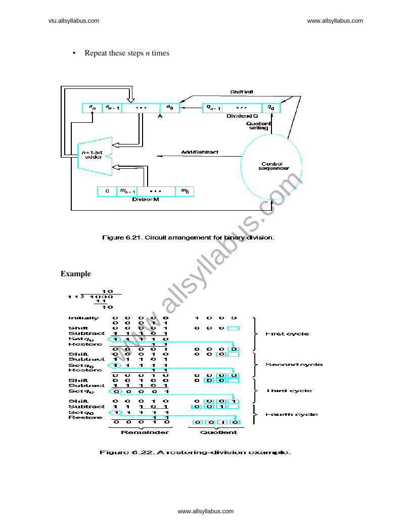
• Repeat these steps n times
Example
www.alls
yllab
us.co
m
vtu.allsyllabus.com www.allsyllabus.com
www.allsyllabus.com
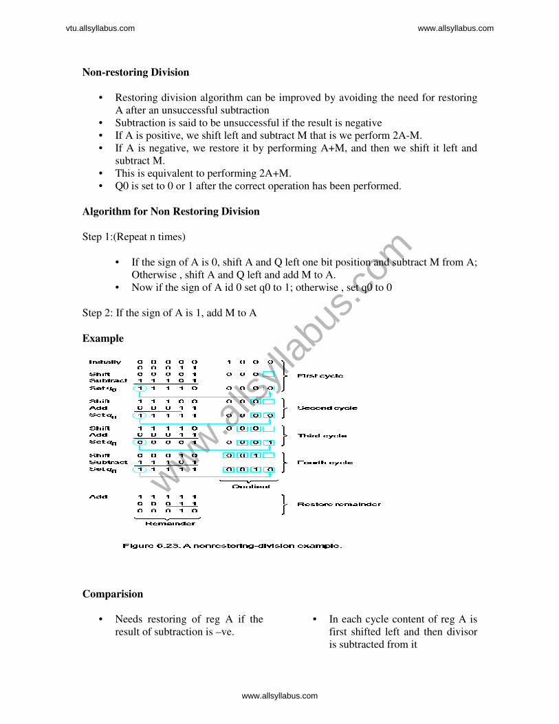
Non-restoring Division
• Restoring division algorithm can be improved by avoiding the need for restoring
A after an unsuccessful subtraction
• Subtraction is said to be unsuccessful if the result is negative
• If A is positive, we shift left and subtract M that is we perform 2A-M.
• If A is negative, we restore it by performing A+M, and then we shift it left and
subtract M.
• This is equivalent to performing 2A+M.
• Q0 is set to 0 or 1 after the correct operation has been performed.
Algorithm for Non Restoring Division
Step 1:(Repeat n times)
• If the sign of A is 0, shift A and Q left one bit position and subtract M from A;
Otherwise , shift A and Q left and add M to A.
• Now if the sign of A id 0 set q0 to 1; otherwise , set q0 to 0
Step 2: If the sign of A is 1, add M to A
Example
Comparision
• Needs restoring of reg A if the
result of subtraction is –ve.
• In each cycle content of reg A is
first shifted left and then divisor
is subtracted from it
www.alls
yllab
us.co
m
vtu.allsyllabus.com www.allsyllabus.com
www.allsyllabus.com

• Does not need restoring of
remainder
• Slower algorithm
• Does not need restoring
• Needs restoring of remainder if
remainder is –ve
• In each cycle the content of reg
A is first shifted left and then the
divisor is added or subtracted
with the content of reg A
depending on the sign of A
• Faster algorithm
Floating-Point Numbers and Operations
• So far we have dealt with fixed-point numbers and have considered them as
integers.
• Floating-point numbers: the binary point is just to the right of the sign bit.
• In the 2’s complement system, the signed value F,represented n-bit binary fraction
B=b0b-1b-2…….b-(n-1)
F(B)= -b0 x20+b-1x2
-1+b-2x2
-2……….b-(n-1)x2
-(n-1)
• Where the range of F is:2 -(n-1)
≤ F ≤ 1-2-(n-1)
• The position of the binary point is variable and is automatically adjusted as
computation proceeds.
• If n=32, then the value range is approximately
2(-31)≤ F ≤ 1-2
-(31) (1-2.3283X10
-10)
• But this range is not sufficient to represent fractional numbers,
• To accommodate very large integers and very small fractions, a computer must be
able to represent numbers and operate on them in such a way that the position of
the binary point is variable and is automatically adjusted as computation proceeds.
• In this case the binary point is said to float, and the numbers are called floating
point numbers.
• What are needed to represent a floating-point decimal number?
• It needs three fields
• Sign
• Mantissa (the significant digits)
• Exponent to an implied base (scale factor)
“Normalized” – the decimal point is placed to the right of the first (nonzero) significant
digit
www.alls
yllab
us.co
m
vtu.allsyllabus.com www.allsyllabus.com
www.allsyllabus.com

• Let us consider the number 111101.1000110 to be represented in floating point
format.
• To represent the number in floating point format, first binary point is shifted to
right of the first bit and the number is multiplied by the scaling factor to get the
same value.
• The number is said to be Normalized form and is given as
111101.1000110 1.11101100110 x 25
IEEE Standard for Floating-Point Numbers
Think about this number (all digits are decimal): ±X1.X2X3X4X5X6X7×10±Y1Y2
.It is
possible to approximate this mantissa precision and scale factor range in a binary
representation that occupies 32 bits: 24-bit mantissa (1 sign bit for signed number), 8-bit
exponent.
Instead of the signed exponent, E, the value actually stored in the exponent field is an
unsigned integer E’=E+127, so called excess-127 format.
Single Precision
101000)2=4010 ; 40-127=-87
Double Precision
Scale factor
Normalized form
Exponent
www.alls
yllab
us.co
m
vtu.allsyllabus.com www.allsyllabus.com
www.allsyllabus.com

Problem
1)Represent 1259.12510 in single precision and double precision formats • Step 1 :Convert decimal number to binary format
1259(10)=10011101011(2)
Fractional Part
0.125 (10)=0.001
• Binary number = 10011101011+0.001
=10011101011.001
Step 2:Normalize the number
10011101011.001=1.0011101011001 x 210
Step3:Single precision format:
For a given number S=0,E=10 and M=0011101011001
Bias for single precision format is = 127
E’=E+127=10+127=137 (10)
=10001001 (2)
• Number in single precision format
0 10001001 0011101011001….0
Exponent Mantissa(23 bit)
Step 4:Double precision format:
For a given number S=0,E=10 and M=0011101011001
Bias for double precision format is = 1023
E’=E+1023=10+1023=1033 (10)
=10000001001 (2)
• Number in double precision format is given as
0 10001001 0011101011001….0 Exponent Mantissa(23 bit)
IEEE Standard
Sign
Sign
www.alls
yllab
us.co
m
vtu.allsyllabus.com www.allsyllabus.com
www.allsyllabus.com

• For excess-127 format, 0 ≤ E’ ≤ 255. However, 0 and 255 are used to represent
special value. So actually 1 ≤ E’ ≤ 254. That means -126 ≤ E ≤ 127.
• Single precision uses 32-bit. The value range is from 2-126
to 2+127
.
• Double precision used 64-bit. The value range is from 2-1022
to 2+1023
.
Normalization
• If a number is not normalized, it can always be put in normalized form by shifting
the fraction and adjusting the exponent. As computations proceed, a number that
does not fall in the representable range of normal numbers might be generated.
• In single precision, it requires an exponent less than -126 (underflow) or greater
than +127 (overflow). Both are exceptions that need to be considered.
Special Values
• The end value 0 and 255 are used to represent special values.
• When E’=0 and M=0, the value exact 0 is represented. (±0)
• When E’=255 and M=0, the value ∞ is represented. (± ∞) • When E’=0 and M≠0, de normal numbers are represented. The value is ±0.M´2
-
126. (allow for Gradual underflow)
• When E’=255 and M≠0, Not a Number (NaN).
• NaN is the result of performing an invalid operation, such as 0/0 or square root of
-1.
Exceptions
www.alls
yllab
us.co
m
vtu.allsyllabus.com www.allsyllabus.com
www.allsyllabus.com

• A processor must set exception flags if any of the following occur in performing
operations: underflow, overflow, divide by zero, inexact, invalid.
• When exception occurs, the results are set to special values.
Arithmetic Operations on Floating-Point Numbers
Add/Subtract rule
1. Choose the number with the smaller exponent and shift its mantissa right a
number of steps equal to the difference in exponents.
2. Set the exponent of the result equal to the larger exponent.
3. Perform addition/subtraction on the mantissas and determine the sign of the result.
4. Normalize the resulting value, if necessary.
Subtraction of floating point numbers
• Similar process is used for subtraction
• Two mantissas are subtracted instead of addition
• Sign of greater mantissa is assigned to the result
Step 1: Compare the exponent for sign bit using 8bit subtractor
Sign is sent to SWAP unit to decide on which number to be sent to
SHIFTER unit.
Step2: The exponent of the result is determined in two way
multiplexer depending on the sign bit from step1
www.alls
yllab
us.co
m
vtu.allsyllabus.com www.allsyllabus.com
www.allsyllabus.com

Step3: Control logic determines whether mantissas are to be
added or subtracted. Depending on sign of the operand.
There are many combinations are possible here, that depends
on sign bits, exponent values of the operand.
Step4: Normalization of the result depending on the leading zeros,
and some special case like 1.xxxxx operands. Where result is 1x.xxx
and X = -1, therefore will increase the exponent value.
Example
Add single precision floating point numbers A
and B, where A=44900000 H and B = 42A00000H.
Solution
Step 1 :Represent numbers in single precision format
A = 0 1000 1001 0010000….0
B = 0 1000 0101 0100000….0
Exponent for A = 1000 1001 =137
Therefore actual exponent = 137-127(Bias) =10
Exponent for B = 1000 0101 = 133
Therefore actual exponent = 133-127(Bias) = 6
With difference 4. Hence its mantissa is shifted right by 4 bits as shown below
Step 2:Shift mantissa
Shifted mantissa of B = 0 0 0 0 0 1 0 0…0
Step 3: Add mantissa
Mantissa of A = 00100000…0
Mantissa of B = 00000100…0
Mantissa of result = 00100100…0
As both numbers are positive, sign of the result is positive
Result =0100 0100 1001 0010 0…0
=44920000H
Multiply rule
• Add the exponents and subtract 127.
• Multiply the mantissas and determine the sign of the result.
• Normalize the resulting value, if necessary.
Divide rule
• Subtract the exponents and add 127.
• Divide the mantissas and determine the sign of the result.
Normalize the resulting value, if necessary
Guard Bits
www.alls
yllab
us.co
m
vtu.allsyllabus.com www.allsyllabus.com
www.allsyllabus.com

• During the intermediate steps, it is important to retain extra bits, often called
guard bits, to yield the maximum accuracy in the final results.
• Removing the guard bits in generating a final result requires truncation of
the extended mantissa.
Truncation
• Chopping – Remove the guard bits
0.b-1b-2b-3000 -- 0.b-1b-2b-3111à0.b-1b-2b-3
Error ranges from 0 to 0.000111.
Chopping is biased because is not symmetrical
about 0, 0 to 1 at LSB.
• Von Neumann Rounding - All 6-bit fractions with b-4b-5b6 not equal to 000
are truncated to to 0.b-1b-21
• This truncation is unbiased, error ranges: -1 to +1 at LSB.
• unbiased rounding is better because positive error tend to offset negative
errors as the computation proceeds.
• Rounding (A 1 is added to the LSB position of the bits to be retained if there
is a 1 in the MSB position of the bits being removed) – unbiased, -½ to +½ at
LSB.
0.b-1b-2b-31 .... is rounded to 0.b-1b-2b-3+ 0.001
� Round to the nearest number or nearest even number in case of a tie
(0.b-1b-20100 -> 0.b-1b-20; 0.b-1b-21100 -> 0.b1b21+0.001)
� Best accuracy
� Most difficult to implement
Addition and Subtraction
Floating point addition is analogous to addition using scientific notation. For example, to
add 2.25x to 1.340625x :
www.alls
yllab
us.co
m
vtu.allsyllabus.com www.allsyllabus.com
www.allsyllabus.com

1. Shift the decimal point of the smaller number to the left until the exponents are
equal. Thus, the first number becomes .0225x .
2. Add the numbers with decimal points aligned:
3. Normalize the result.
Once the decimal points are aligned, the addition can be performed by ignoring the
decimal point and using integer addition.
The addition of two IEEE FPS numbers is performed in a similar manner. The number
2.25 in IEEE FPS is:
The number 134.0625 in IEEE FPS is:
1. To align the binary points, the smaller exponent is incremented and the mantissa
is shifted right until the exponents are equal. Thus, 2.25 becomes:
2. The mantissas are added using integer addition:
3. The result is already in normal form. If the sum overflows the position of the
hidden bit, then the mantissa must be shifted one bit to the right and the exponent
incremented. The mantissa is always less than 2, so the hidden bits can sum to no
more than 3 (11).
The exponents can be positive or negative with no change in the algorithm. A smaller
exponent means more negative. In the bias-127 representation, the smaller exponent has
the smaller value for E, the unsigned interpretation.
www.alls
yllab
us.co
m
vtu.allsyllabus.com www.allsyllabus.com
www.allsyllabus.com
An important case occurs when the numbers differ widely in magnitude. If the exponents
differ by more than 24, the smaller number will be shifted right entirely out of the
mantissa field, producing a zero mantissa. The sum will then equal the larger number.
Such truncation errors occur when the numbers differ by a factor of more than ,
which is approximately . The precision of IEEE single precision floating point
arithmetic is approximately 7 decimal digits.
Negative mantissas are handled by first converting to 2's complement and then
performing the addition. After the addition is performed, the result is converted back to
sign-magnitude form.
When adding numbers of opposite sign, cancellation may occur, resulting in a sum which
is arbitrarily small, or even zero if the numbers are equal in magnitude. Normalization in
this case may require shifting by the total number of bits in the mantissa, resulting in a
large loss of accuracy.
When the mantissa of the sum is zero, no amount of shifting will produce a 1 in the
hidden bit. This case must be detected in the normalization step and the result set to the
representation for 0, E = M = 0. This result does not mean the numbers are equal; only
that their difference is smaller than the precision of the floating point representation.
Floating point subtraction is achieved simply by inverting the sign bit and performing
addition of signed mantissas as outlined above.
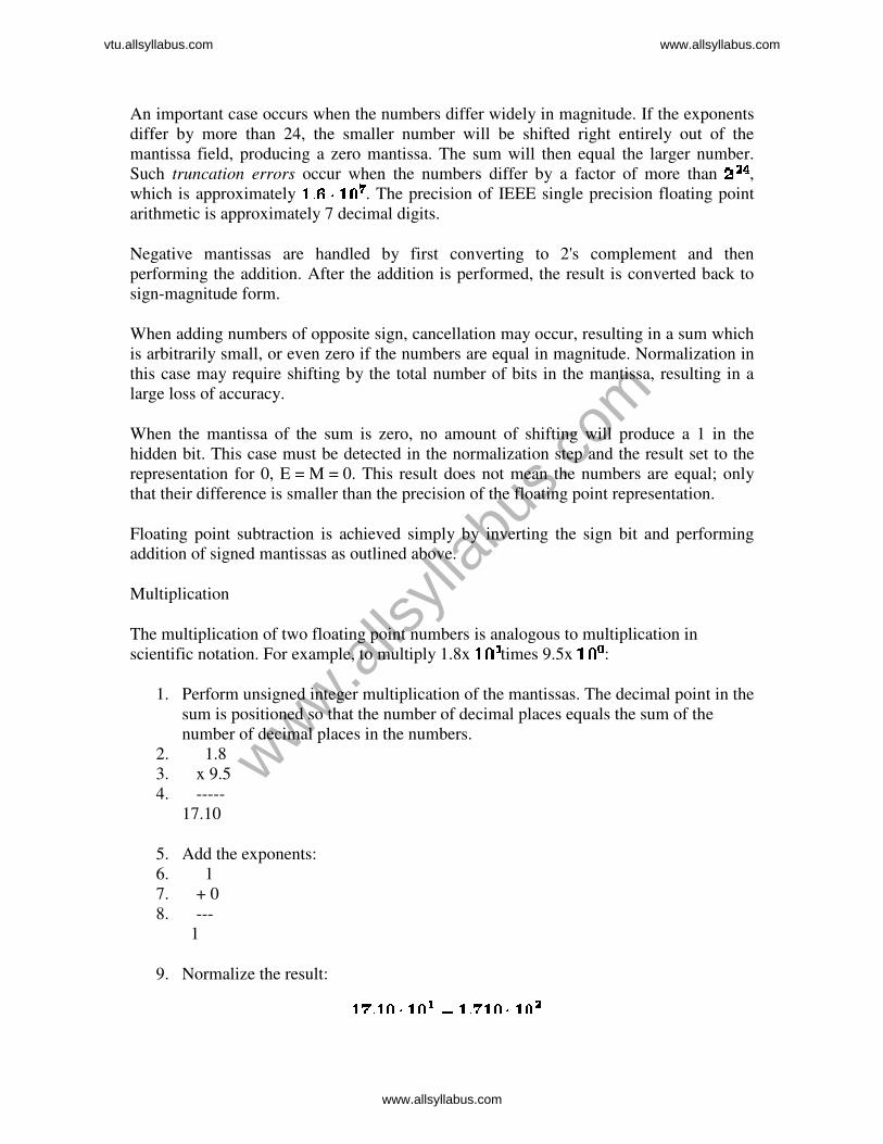
Multiplication
The multiplication of two floating point numbers is analogous to multiplication in
scientific notation. For example, to multiply 1.8x times 9.5x :
1. Perform unsigned integer multiplication of the mantissas. The decimal point in the
sum is positioned so that the number of decimal places equals the sum of the
number of decimal places in the numbers.
2. 1.8
3. x 9.5
4. -----
17.10
5. Add the exponents:
6. 1
7. + 0
8. ---
1
9. Normalize the result:
www.alls
yllab
us.co
m
vtu.allsyllabus.com www.allsyllabus.com
www.allsyllabus.com

10. Set the sign of the result.
The multiplication of two IEEE FPS numbers is performed similarly. The number 18.0 in
IEEE FPS format is:
The number 9.5 in IEEE FPS format is:
1. The product of the 24 bit mantissas produces a 48 bit result with 46 bits to the
right of the binary point:
Truncated to 24 bits with the hidden bit in (), the mantissa is:
2. The biased-127 exponents are added. Addition in biased-127 representation can
be performed by 2's complement with an additional bias of -127 since:
The sum of the exponents is:
E
1000 0011 (4)
+ 1000 0010 (3)
-----------
0000 0101
+ 1000 0001 (-127)
-----------
1000 0110 (+7)
3. The mantissa is already in normal form. If the position of the hidden bit
overflows, the mantissa must be shifted right and the exponent incremented.
4. The sign of the result is the xor of the sign bits of the two numbers.
When the fields are assembled in IEEE FPS format, the result is:
www.alls
yllab
us.co
m
vtu.allsyllabus.com www.allsyllabus.com
www.allsyllabus.com

Rounding occurs in floating point multiplication when the mantissa of the product is
reduced from 48 bits to 24 bits. The least significant 24 bits are discarded.
Overflow occurs when the sum of the exponents exceeds 127, the largest value which is
defined in bias-127 exponent representation. When this occurs, the exponent is set to 128
(E = 255) and the mantissa is set to zero indicating + or - infinity.
Underflow occurs when the sum of the exponents is more negative than -126, the most
negative value which is defined in bias-127 exponent representation. When this occurs,
the exponent is set to -127 (E = 0). If M = 0, the number is exactly zero.
If M is not zero, then a denormalized number is indicated which has an exponent of -127
and a hidden bit of 0. The smallest such number which is not zero is . This number
retains only a single bit of precision in the rightmost bit of the mantissa.
www.alls
yllab
us.co
m
vtu.allsyllabus.com www.allsyllabus.com
www.allsyllabus.com