Embed Size (px)
Citation preview
1
Project Report
On
SETTING UP OF ELECTROPLATING UNIT
FOR FABRICATION OF AGRICULTURAL
TOOLS
Submitted in Partial Fulfilment of the requirement for the award of degree of
Bachelor Engineering
In
Mechanical Engineering
BY
Kumar Saheb Manoj Kumar Rajput Apoorva Kumar
1PI10ME061 1PI10ME065 1PI10ME024
Under the guidance of
Dr. C. S. RAMESH
Professor
Department of Mechanical Engineering
PES Institute of Technology
2
PEOPLES EDUCATION SOCIETY
I N S T I T U T E O F T E C H N O L O G Y
100 Feet Ring Road, BSK III Stage, Bangalore - 560 085.
Tel : 26721983
DEPARTMENT OF MECHANICAL ENGINEERING
C E R T I F I C A T E
Certified that the mini project entitled “Setting up of electroplating unit for the
fabrication of agricultural tools” is a bonafide work carried out by Kumar Saheb
(1PI10ME061), Manoj Kumar Rajput (1PI10ME065) and Apoorva Kumar
(1PI10ME024) in partial fulfillment for the award of degree of Bachelor of Engineering
in Mechanical engineering of the Visveswaraya Technological University, Belgaum
during the year 2013 - 2014. It is certified that all corrections/suggestions indicated for
Internal Assessment have been incorporated in the report deposited in the
departmental library. The project report has been approved as it satisfies the academic
requirements in respect of project work prescribed for the Bachelor of Engineering
Degree.
Dr C.S Ramesh Dr K.S Sridhar
Professor, HOD,
Dept of Mech Engg, Dept of Mech Engg,
Pesit,Bangalore Pesit,Bangalore
Signature of the examiners
(Examiner 1) (Examiner 2)
3
DECLRATION
I hereby declare that the project work entitled “SETTING UP OF
ELECTROPLATING UNIT FOR FABRICATION OF
AGRICULTURAL TOOLS” submitted to PES Institute of
Technology, is a record of an original work done by us under
the guidance of Dr. C. S. Ramesh Professor, PES Institute of
Technology, Bangalore, and this project work has not
performed the basis for award of any Degree or Diploma/
Associate ship/ Fellowship and similar project if any.
Kumar Saheb Manoj Kumar Rajput Apoorva Kumar
(1PI10ME061) (IPI10ME065) (1PI10ME024)
4
ACKNOWLEDGEMENT
The satisfaction and euphoria that accompany the successful completion
of any task would be incomplete without the mention of the people who
made it possible, whose constant guidance and encouragement crowned
out effort with success.
We express our deep sense of gratitude to my
guide Dr. C.S Ramesh, Professor, P.E.S. Institute of Technology
Bangalore for his untiring and valuable guidance with constant
encouragement at every stage of this project work. We are grateful to Dr.
K.S. Sridhar, Professor& Head of the Department of Mechanical
Engineering, P.E.S. Institute of technology for giving me the consent to
carry out the dissertation work. We also express my sincere gratitude to
Dr. K.N. Balasubramanya Murthy, Principal & Director, P.E.S. Institute of
technology, Bangalore for permitting to carry out the dissertation work.
We
sincerely thank Dr. K.T. Kashayp, Professor, Department Mechanical
Engineering, P.E.S Institute of technology for his constant support in
carrying out project work. I sincerely thank Dr. Rajesh Mathivanan N,
Associate Professor, Department Mechanical Engineering, P.E.S Institute
of technology for his constant support and valuable advice
We are very grateful to all the teaching, non-teaching, and administrative
staff of Department of Mechanical Engineering, P.E.S. Institute of
Technology for their kind co-operation during this work. Finally, we thank
to almighty, Our Parents, friends for their help and support throughout our
course and all who have helped me directly and indirectly during this
course of project
5
ABSTRACT
Low carbon steel with manganese as a major alloying element is the most
popular material for fabrication of harvester blades. During harvesting,
these blades tend to get corroded and also get worn out quickly due to the
abrasive and erosive nature of the hard particles of soil. This leads to huge
problems of either getting the worn harvester blades replaced by a new
set of blades resulting in uncalled increased farming investments. In
recent years, surface engineering methods offer solutions to the address
the above issues in farming.
In the light of the above, this work focuses on nickel-silicon carbide
composite electroplating of harvester blades. Nickel electroplating is
commercially proven technique with it unique advantages being low
temperature process and easily the most economical one. Nickel coatings
offer excellent corrosion resistance even under harsh environment during
farming. SiC has been used to enhance hardness of the blade.
Erosive wear of the coated and uncoated harvester blade material will be
characterized using air jet erosive wear test rig. The effect of standoff
distance (50 mm,40mm,30mm,20mm) and test duration time (5,10,15,20
minutes),Vickers hardness value of both coated and uncoated harvester
blade material is reported.
6
TABLE OF CONTENTS
Cover page..............................................................................................1
Certificate …………………………………………………………………..…2
Declaration .............................................................................................3
Acknowledgements... .............................................................................4
Abstract…………….................................................................................5
Table of Contents…………………………………………………….…. .....6
Chapter 1: Introduction .........................................................................8
1.1: Aim of the Project
1.2: Present scenario
Chapter 2: Brief Literature survey…….………………..........................9
2.1: Advantage of Composite coating over base alloy coating.
2.2: Air Jet erosion test over MMC’s
Chapter 3: The Combined harvester ………………………………… 13
3.1: Functions and working
3.2: Parameters affecting combined harvester blades
Chapter 4: Experimental Procedure...................................................20
4.1: Chemical composition test
4.1.1: Principal of the test
7
4.1.2: Result of the test
4.2: Hardness test before the electroplating
4.2.1: Principal of the test
4.2.2: Result of the test
4.3: The electroplating process
4.3.1: The coating process
4.3.2: Why Nickel as base metal for electroplating?
4.3.3: Why SiC used as reinforcement?
4.3.4: Electroplating experimental procedure
4.4: Hardness test after the electroplating
4.5: Air jet erosive Wear test
4.5.1: Air jet tester details
4.5.2: Test condition and parameter
4.5.3: Observations and Results
4.5.3.1: Effect of varying stand of distance
4.5.3.2: Effect of varying test duration
Chapter 5: Conclusion and Future work...........................................47
Chapter 6: References........................................................................48
8
CHAPTER 1
Introduction
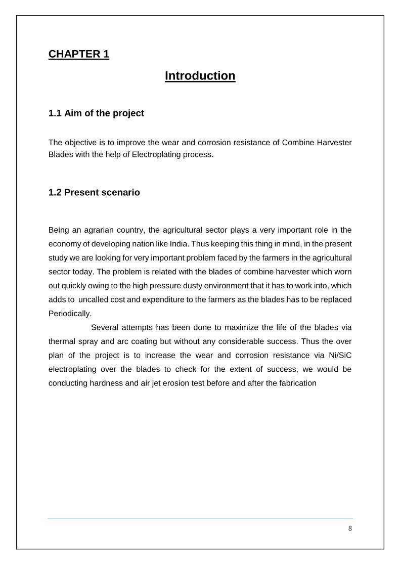
1.1 Aim of the project
The objective is to improve the wear and corrosion resistance of Combine Harvester
Blades with the help of Electroplating process.
1.2 Present scenario
Being an agrarian country, the agricultural sector plays a very important role in the
economy of developing nation like India. Thus keeping this thing in mind, in the present
study we are looking for very important problem faced by the farmers in the agricultural
sector today. The problem is related with the blades of combine harvester which worn
out quickly owing to the high pressure dusty environment that it has to work into, which
adds to uncalled cost and expenditure to the farmers as the blades has to be replaced
Periodically.
Several attempts has been done to maximize the life of the blades via
thermal spray and arc coating but without any considerable success. Thus the over
plan of the project is to increase the wear and corrosion resistance via Ni/SiC
electroplating over the blades to check for the extent of success, we would be
conducting hardness and air jet erosion test before and after the fabrication
9
Chapter 2
Brief Literature survey
2.1 Advantage of Composite coating over base alloy coating
Coatings are used in both aqueous and high temperature applications. Electric power
generation, and waste incineration involve severe conditions and thick coatings have
proved effective. Diesel and gas turbine engines are subjects of the high temperature
corrosion and highly beneficial coatings have been developed. Some nuclear power
systems also rely on coatings. Factors that must be taken into account include
substrate compatibility, adhesion, porosity, the possibility of repair or recoating,
interdiffusion, the effect of thermal cycling, resistance to wear and corrosion, and not
at last the cost.
Advances in materials performance often require the development of
composite systems. Coated materials could be one form to use. The abrasion and
corrosion resistance of components can be greatly increased by protective coatings
and this is a growing industry of considerable economic importance. Both
measurements of electrochemical corrosion and friction coefficient show a better
resistance of nano-structured composite coating compared with pure nickel coating.
The nano-composite coating show a bigger polarisation resistance and reduced
corrosion current density compared with pure nickel coating in moving conditions. The
friction coefficient of nano-composite coating is smaller compared with pure nickel
coating.
Deposition of electrochemical composite coatings (ECC) is not a newly
developed technique [1], but has been in continuous development since the 1970s [2–
9]. The steady interest is explained by easy maintainability and low cost of ECC
manufacture as well as by a possibility of changing the properties and adapting them
to many applications. Due to their high wear resistance and the low cost of ceramic
powder, Ni–SiC composites have been investigated to the greatest extent and
10
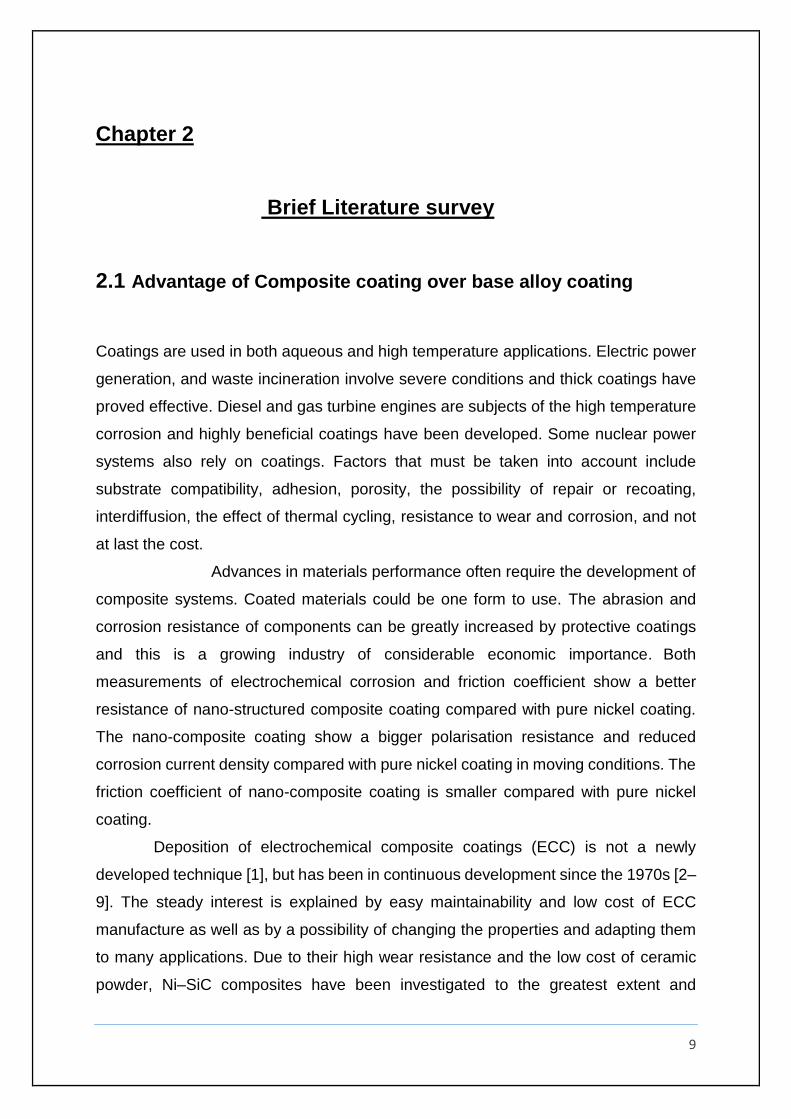
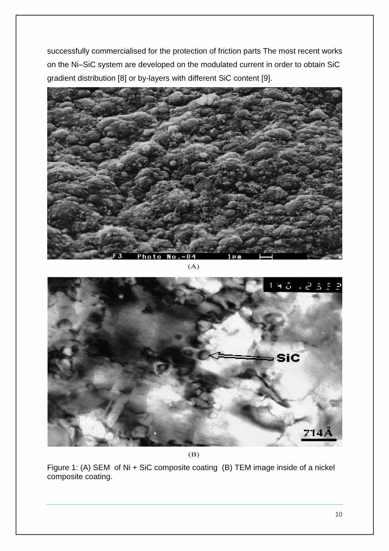
successfully commercialised for the protection of friction parts The most recent works
on the Ni–SiC system are developed on the modulated current in order to obtain SiC
gradient distribution [8] or by-layers with different SiC content [9].
Figure 1: (A) SEM of Ni + SiC composite coating (B) TEM image inside of a nickel composite coating.
11
2.1 Air Jet erosion over MMC’S
Metal matrix composites (MMC’s) are presently the most preferred innovative
materials due to their excellent strength, higher wear resistance, better thermal
conductivity and low coefficient of thermal expansion. It has been nearly three
decades, that these exotic materials are mainly processed by two well established
techniques namely the powder and liquid metallurgy. Homogeneity in the distribution
and high volume fractions of reinforcements in the matrix alloy are the characteristics
features of the powder metallurgical processing technique. However, the liquid
metallurgy processing technique possesses unique features such as mass production
of large and complex shaped composite castings. A blend of the above two processes
will positively bring out enhanced homogeneity, greater volume incorporation of
reinforcements, leading to production of light weight large structures with improved
mechanical and tribological properties of the composites [10]. It has been re-ported
that increased content of hard reinforcement in the soft matrix alloy has resulted in
effective decrease in wear rates of the composites [11]. Majority of the metal matrix
composite materials systems studied are reinforced with ceramics possessing high
hardness and strength either continuous in the form of fibre or discontinuous in the
form of whisker, platelets or particulate reinforcements embedded in a ductile metallic
matrix [12]. Most of the researchers have focused their attention on 9
Processing and characterization of mechanical and adhesive wear behaviour of
MMC’s [13,14,15]. Currently MMC’s are being explored as the candidate materials for
components subjected to hard solid particle erosion. Merger information is available
as regards the assessment of solid particle erosion wear of MMC’s although
researchers have reported on erosive wear behaviour of polymer based composites
[16,17]. Decrease in the angle of impact from 90˚ to 20˚ has resulted in significant
increase in erosion wear loss and ductility [18]. The mass loss of the target material
subjected to sand particle erosion tests is directly proportional to kinetic energy and is
inversely to the hardness of the target material [19]. Metal matrix composites with
silicon carbide as the reinforcement possesses the maximum erosion wear resistance
its mass fraction ranging from 60 to 75 Weight% [20]. Interesting work on erosive wear
of polymer based composites has been reported. Factors such as impingement angle,
12
impact velocity, erodent size and amount of reinforcement are the major factors
affecting the erosion rate of composites [21,17]. It has been reported that glass and
carbon fibre reinforced composites do exhibit semi-ductile erosion characteristics with
the peak erosion wear occurring at 60˚ impingement angle [22,23]. Hybridization of
the reinforcements with use of discontinuous fibres and hard particulates in processing
of MMC’s leads to improved hardness, strength and wear resistance. However, no
information is available as regards the erosive wear of hybrid MMC’s with hard
particulate and discontinuous fibre reinforcements. In the light of the above, this work
focuses on novel processing of hybrid MMC’s and assessing its erosive wear
behaviour.
13
Chapter 3
The Combined harvester
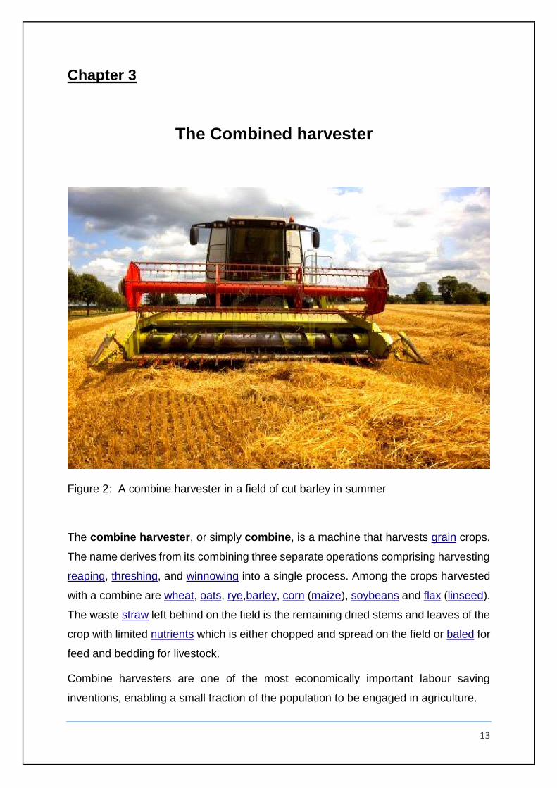
Figure 2: A combine harvester in a field of cut barley in summer
The combine harvester, or simply combine, is a machine that harvests grain crops.
The name derives from its combining three separate operations comprising harvesting
reaping, threshing, and winnowing into a single process. Among the crops harvested
with a combine are wheat, oats, rye,barley, corn (maize), soybeans and flax (linseed).
The waste straw left behind on the field is the remaining dried stems and leaves of the
crop with limited nutrients which is either chopped and spread on the field or baled for
feed and bedding for livestock.
Combine harvesters are one of the most economically important labour saving
inventions, enabling a small fraction of the population to be engaged in agriculture.

14
3.1 How does it work?
The crops we grow in our fields, such as wheat, barley, and rye, are only partly edible.
We can use the seeds at the top of each plant (known as the grain) to make products
like bread and cereal, but the rest of the plant (the chaff) is inedible and has to be
discarded.
Before modern-day machines were developed, agricultural workers had to
harvest crops by carrying out a series of laborious operations one after another. First
they had to cut down the plants with a long-handled cutting tool such as a scythe.
Next, they had to separate the edible grain from the inedible chaff by beating the cut
stalks—an operation known as threshing. Finally, they had to clean any remaining
debris away from the seeds to make them suitable for use in a mill. All this took a lot
of time and a lot of people.
Thankfully, modern combine harvesters do the whole job
automatically: you simply drive them through a field of growing crops and they cut,
thresh, and clean the grains all by themselves using rotating blades, wheels, sieves,
and elevators. The grain collects in a tank inside the combine harvester (which is
periodically emptied into tractors that drive alongside), while the chaff spurts from a
big exit pipe at the back and falls back down onto the field.
Figure 3: Wheat crop
15
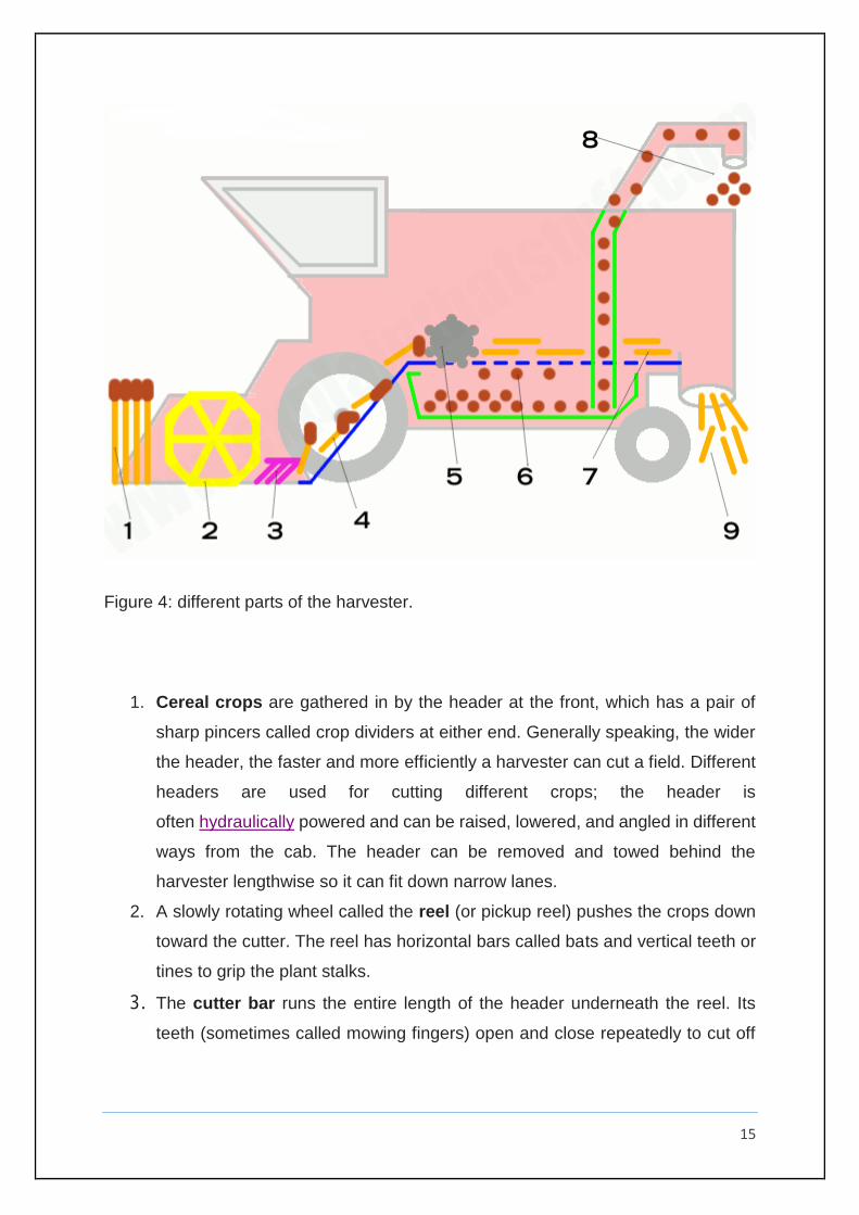
Figure 4: different parts of the harvester.
1. Cereal crops are gathered in by the header at the front, which has a pair of
sharp pincers called crop dividers at either end. Generally speaking, the wider
the header, the faster and more efficiently a harvester can cut a field. Different
headers are used for cutting different crops; the header is
often hydraulically powered and can be raised, lowered, and angled in different
ways from the cab. The header can be removed and towed behind the
harvester lengthwise so it can fit down narrow lanes.
2. A slowly rotating wheel called the reel (or pickup reel) pushes the crops down
toward the cutter. The reel has horizontal bars called bats and vertical teeth or
tines to grip the plant stalks.
3. The cutter bar runs the entire length of the header underneath the reel. Its
teeth (sometimes called mowing fingers) open and close repeatedly to cut off

16
the crops at their base, a bit like a giant electric hedge cutter sweeping along
at ground level.
Figure 5: Close-up of the cutter on a John Deere combine harvester. Left: Looking
from the front; Right: looking down from the cab toward the incoming crops.
4. Behind the cutter bar, the cut crops are fed toward the centre by spinning augurs
(screws) and travel up a conveyor to the processing mechanism inside the main part
of the combine.
5. A threshing drum beats the cut crops to break and shake the grains away from
their stalks.
6. The grains fall through sieves into a collecting tank below.
7. The chaff (unwanted material) passes along conveyors called straw
walkers toward the back of the machine. More grain falls through into the tank.
8. When the grain tank is full, a tractor with a trailer on the back pulls alongside the
combine. The grain is carried up from the tank by an elevator and shoots out of a side
pipe (sometimes called the unloader) into the trailer.
17
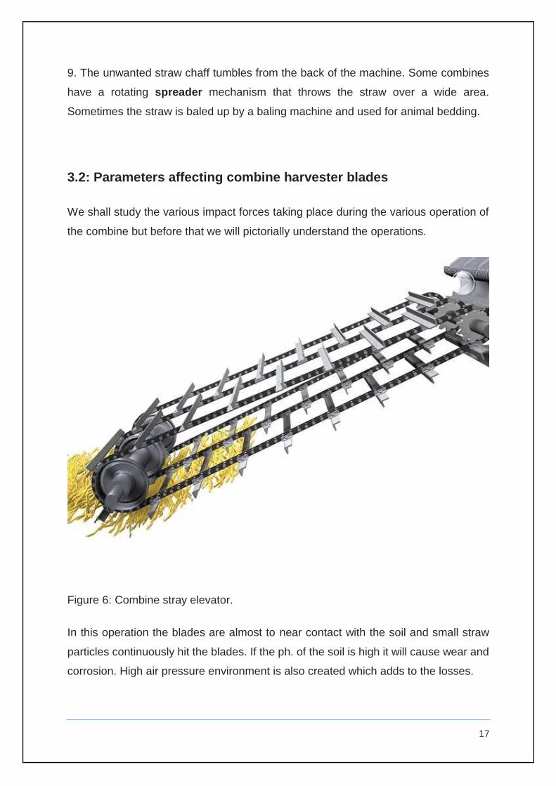
9. The unwanted straw chaff tumbles from the back of the machine. Some combines
have a rotating spreader mechanism that throws the straw over a wide area.
Sometimes the straw is baled up by a baling machine and used for animal bedding.
3.2: Parameters affecting combine harvester blades
We shall study the various impact forces taking place during the various operation of
the combine but before that we will pictorially understand the operations.
Figure 6: Combine stray elevator.
In this operation the blades are almost to near contact with the soil and small straw
particles continuously hit the blades. If the ph. of the soil is high it will cause wear and
corrosion. High air pressure environment is also created which adds to the losses.
18
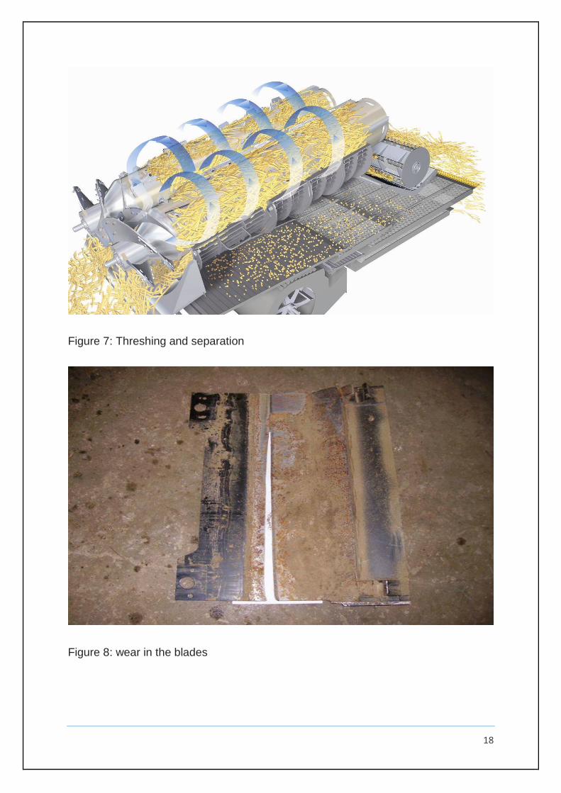
Figure 7: Threshing and separation
Figure 8: wear in the blades

19
The impact on the blades include the soil and dusty hitting the blades at various angles
which will be studied in the air jet erosion test.
20
CHAPTER 4
EXPERIMENTAL PROCEDURE
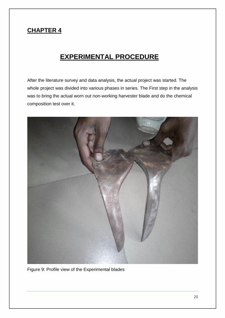
After the literature survey and data analysis, the actual project was started. The
whole project was divided into various phases in series. The First step in the analysis
was to bring the actual worn out non-working harvester blade and do the chemical
composition test over it.
Figure 9: Profile view of the Experimental blades
21
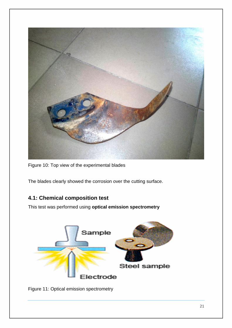
Figure 10: Top view of the experimental blades
The blades clearly showed the corrosion over the cutting surface.
4.1: Chemical composition test
This test was performed using optical emission spectrometry
Figure 11: Optical emission spectrometry
22
4.1.1: Principle of the test
Optical emission spectrometry involves applying electrical energy in the form of spark
generated between an electrode and a metal sample, whereby the vaporized atoms
are brought to a high energy state within a so-called “discharge plasma”.
These excited
atoms and ions in the discharge plasma create a unique emission spectrum specific
to each element. Thus, a single element generates numerous characteristic emission
spectral lines.
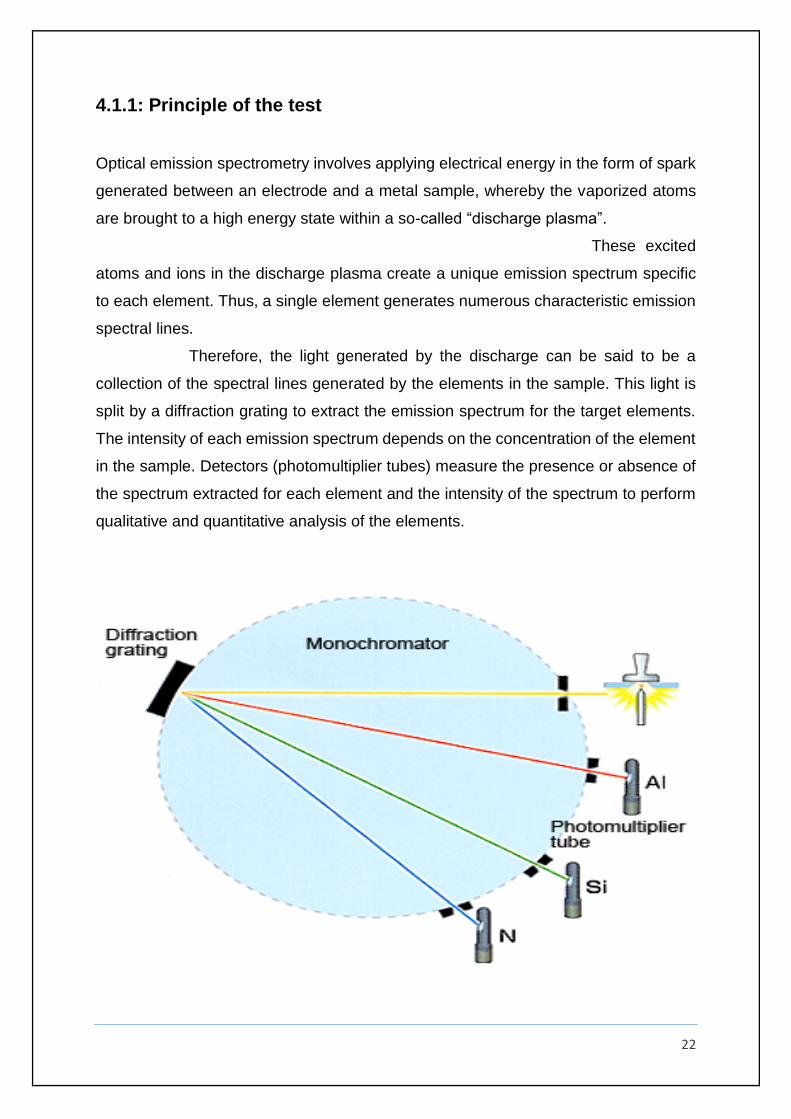
Therefore, the light generated by the discharge can be said to be a
collection of the spectral lines generated by the elements in the sample. This light is
split by a diffraction grating to extract the emission spectrum for the target elements.
The intensity of each emission spectrum depends on the concentration of the element
in the sample. Detectors (photomultiplier tubes) measure the presence or absence of
the spectrum extracted for each element and the intensity of the spectrum to perform
qualitative and quantitative analysis of the elements.
23
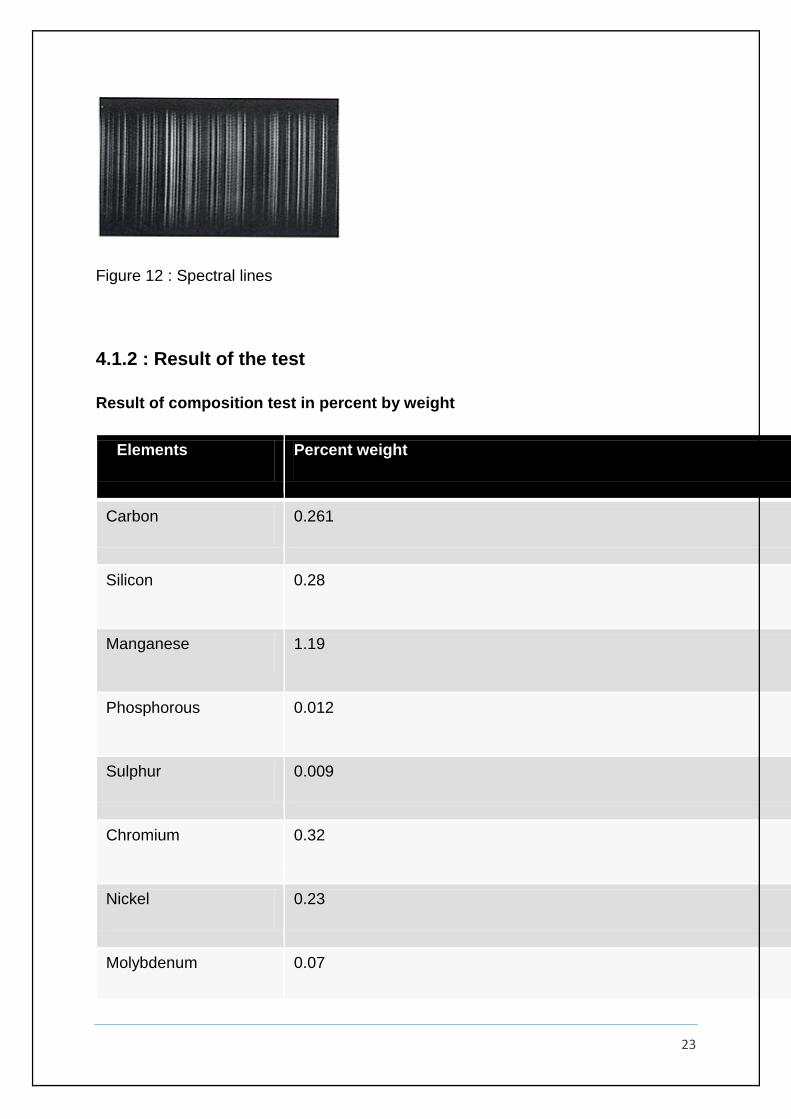
Figure 12 : Spectral lines
4.1.2 : Result of the test
Result of composition test in percent by weight
EElements Percent weight
Carbon 0.261
Silicon 0.28
Manganese 1.19
Phosphorous 0.012
Sulphur 0.009
Chromium 0.32
Nickel 0.23
Molybdenum 0.07
24
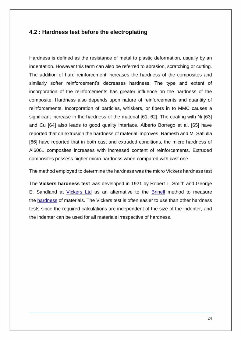
4.2 : Hardness test before the electroplating
Hardness is defined as the resistance of metal to plastic deformation, usually by an
indentation. However this term can also be referred to abrasion, scratching or cutting.
The addition of hard reinforcement increases the hardness of the composites and
similarly softer reinforcement’s decreases hardness. The type and extent of
incorporation of the reinforcements has greater influence on the hardness of the
composite. Hardness also depends upon nature of reinforcements and quantity of
reinforcements. Incorporation of particles, whiskers, or fibers in to MMC causes a
significant increase in the hardness of the material [61, 62]. The coating with Ni [63]
and Cu [64] also leads to good quality interface. Alberto Borrego et al. [65] have
reported that on extrusion the hardness of material improves. Ramesh and M. Safiulla
[66] have reported that in both cast and extruded conditions, the micro hardness of
Al6061 composites increases with increased content of reinforcements. Extruded
composites possess higher micro hardness when compared with cast one.
The method employed to determine the hardness was the micro Vickers hardness test
The Vickers hardness test was developed in 1921 by Robert L. Smith and George
E. Sandland at Vickers Ltd as an alternative to the Brinell method to measure
the hardness of materials. The Vickers test is often easier to use than other hardness
tests since the required calculations are independent of the size of the indenter, and
the indenter can be used for all materials irrespective of hardness.
25
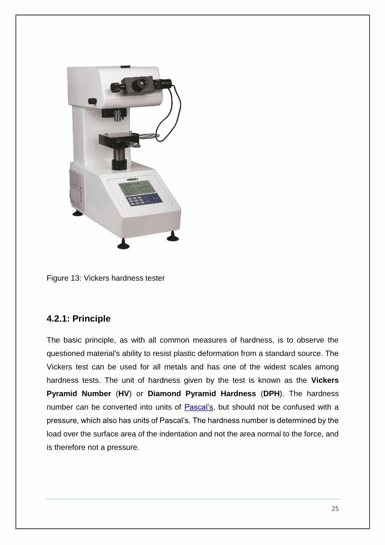
Figure 13: Vickers hardness tester
4.2.1: Principle
The basic principle, as with all common measures of hardness, is to observe the
questioned material's ability to resist plastic deformation from a standard source. The
Vickers test can be used for all metals and has one of the widest scales among
hardness tests. The unit of hardness given by the test is known as the Vickers
Pyramid Number (HV) or Diamond Pyramid Hardness (DPH). The hardness
number can be converted into units of Pascal’s, but should not be confused with a
pressure, which also has units of Pascal’s. The hardness number is determined by the
load over the surface area of the indentation and not the area normal to the force, and
is therefore not a pressure.
26
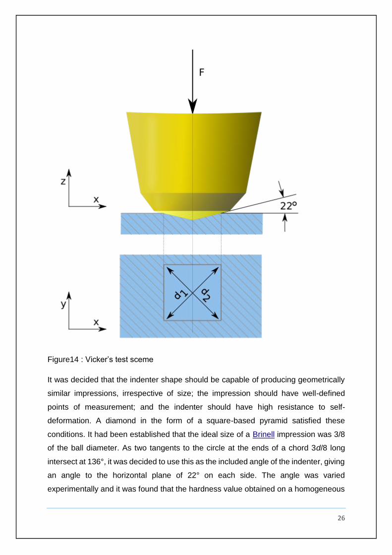
Figure14 : Vicker’s test sceme
It was decided that the indenter shape should be capable of producing geometrically
similar impressions, irrespective of size; the impression should have well-defined
points of measurement; and the indenter should have high resistance to self-
deformation. A diamond in the form of a square-based pyramid satisfied these
conditions. It had been established that the ideal size of a Brinell impression was 3/8
of the ball diameter. As two tangents to the circle at the ends of a chord 3d/8 long
intersect at 136°, it was decided to use this as the included angle of the indenter, giving
an angle to the horizontal plane of 22° on each side. The angle was varied
experimentally and it was found that the hardness value obtained on a homogeneous
27
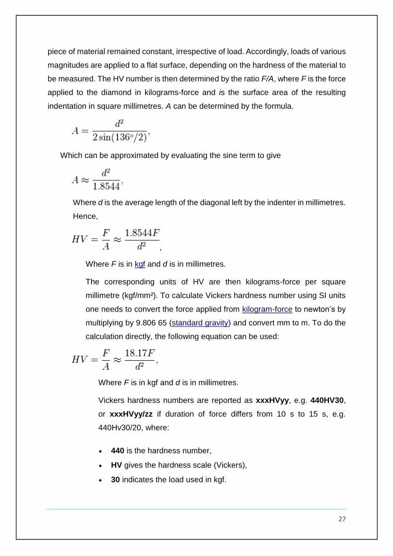
piece of material remained constant, irrespective of load. Accordingly, loads of various
magnitudes are applied to a flat surface, depending on the hardness of the material to
be measured. The HV number is then determined by the ratio F/A, where F is the force
applied to the diamond in kilograms-force and is the surface area of the resulting
indentation in square millimetres. A can be determined by the formula.
Which can be approximated by evaluating the sine term to give
Where d is the average length of the diagonal left by the indenter in millimetres.
Hence,
,
Where F is in kgf and d is in millimetres.
The corresponding units of HV are then kilograms-force per square
millimetre (kgf/mm²). To calculate Vickers hardness number using SI units
one needs to convert the force applied from kilogram-force to newton’s by
multiplying by 9.806 65 (standard gravity) and convert mm to m. To do the
calculation directly, the following equation can be used:
Where F is in kgf and d is in millimetres.
Vickers hardness numbers are reported as xxxHVyy, e.g. 440HV30,
or xxxHVyy/zz if duration of force differs from 10 s to 15 s, e.g.
440Hv30/20, where:
440 is the hardness number,
HV gives the hardness scale (Vickers),
30 indicates the load used in kgf.
28
20 indicates the loading time if it differs from 10 s to 15 s
Vickers values are generally independent of the test force: they will
come out the same for 500 gf and 50 kgf, as long as the force is at least
200 gf.
For thin samples indentation depth can be an issue due to substrate
effects. As a general rule of thumb the sample thickness should be kept
greater than 2.5 times the indent diameter. Alternatively indent depth
can be calculated according to:
5.2.2 : Hardness test result
Trial 1 478 HV
Trial 2 486 HV
Trial 3 482 HV
Average value 482 HV
5.3 : The electroplating process
Electroplating is a process that uses electrical current to reduce dissolved
metal cations so that they form a coherent metal coating on an electrode. The term is
also used for electrical oxidation of anions onto a solid subtrate, as in the formation
silver chloride on silver wire to make silver/silver-chloride electrodes. Electroplating is
primarily used to change the surface properties of an object (e.g. abrasion and wear
resistance, corrosion protection,lubricity, aesthetic qualities, etc.), but may also be
used to build up thickness on undersized parts or to form objects by electroforming.
29
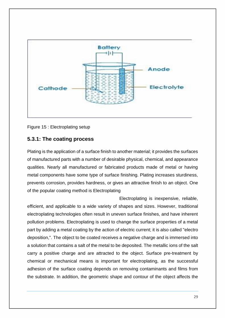
Figure 15 : Electroplating setup
5.3.1: The coating process
Plating is the application of a surface finish to another material; it provides the surfaces
of manufactured parts with a number of desirable physical, chemical, and appearance
qualities. Nearly all manufactured or fabricated products made of metal or having
metal components have some type of surface finishing. Plating increases sturdiness,
prevents corrosion, provides hardness, or gives an attractive finish to an object. One
of the popular coating method is Electroplating
Electroplating is inexpensive, reliable,
efficient, and applicable to a wide variety of shapes and sizes. However, traditional
electroplating technologies often result in uneven surface finishes, and have inherent
pollution problems. Electroplating is used to change the surface properties of a metal
part by adding a metal coating by the action of electric current; it is also called "electro
deposition,". The object to be coated receives a negative charge and is immersed into
a solution that contains a salt of the metal to be deposited. The metallic ions of the salt
carry a positive charge and are attracted to the object. Surface pre-treatment by
chemical or mechanical means is important for electroplating, as the successful
adhesion of the surface coating depends on removing contaminants and films from
the substrate. In addition, the geometric shape and contour of the object affects the
30
thickness of the deposited layer. Objects with sharp corners and features will have
thicker deposits on the outside corners and thinner ones in the recessed areas,
because the current flows more densely to prominent points than to less accessible
areas. This characteristic of electroplating limits applications with uneven surfaces or
that have depressions or hidden holes. Some metals used in electroplating are
aluminium, brass, bronze, cadmium, copper, chromium, iron, lead, nickel, tin, and zinc,
as well as precious metals such as gold, platinum, and silver. Different types of
coatings can be achieved through control of parameters such as voltage, amperage,
temperature, residence times, and purity of the bath solutions. Applications of
electroplating are numerous because it is an inexpensive and simple method; it is used
in all aspects of electronics, optics, and the automobile industry where, for example,
chrome plating is used to enhance the corrosion resistance of metal parts .
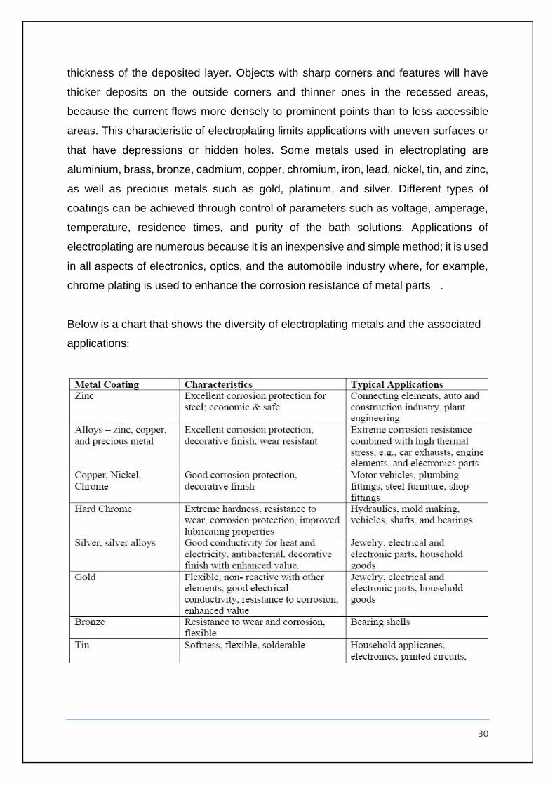
Below is a chart that shows the diversity of electroplating metals and the associated
applications:
31
4.3.2: Why Nickel chosen as a base element for electroplating?
Nickel electroplating is a commercially important and versatile surface-finishing
process. Its commercial importance may be judged from the amount of nickel in the
form of metal and salts consumed annually for electroplating, now roughly 100,000
metric tons worldwide, as well as its versatility from its many current applications. The
applications of nickel electroplating fall into three main categories: decorative,
functional, and electroforming.
In decorative applications, electroplated nickel is most often applied in combination
with electrodeposited chromium. The thin layer of chromium was first specified to
prevent the nickel from tarnishing. It was originally deposited on top of a relatively
thick, single layer of nickel that had been polished and buffed to a mirror-bright finish.
Today decorative nickel coatings are mirror bright as deposited and do not require
polishing prior to chromium plating. Multi-layered nickel coatings outperform single-
layer ones of equal thickness and are widely specified to protect materials exposed to
severely corrosive conditions. The corrosion performance of decorative, electroplated
nickel plus chromium coatings has been further improved by the development of
processes by which the porosity of chromium can be varied and controlled on a
microscopic scale (micro discontinuous chromium). Modern multi-layered nickel
coatings in combination with micro discontinuous chromium are capable of protecting
steel, zinc, copper, aluminium, and many other materials from corrosion for extended
periods of time. The complexity of modern-day nickel plus chromium coatings is more
than offset by the greatly improved corrosion resistance that has been achieved
without significantly increasing coating thickness and costs.
There are many functional applications where decoration is not the issue. Instead,
nickel and nickel alloys with matte or dull finishes are deposited on surfaces to improve
corrosion and wear resistance or modify magnetic and other properties. The properties
of nickel electrodeposits produced under different conditions of operation are of
particular interest in this connection. Electroforming is electroplating applied to the
fabrication of products of various kinds. Nickel is deposited onto a mandrel and then
32
removed from it to create a part made entirely of nickel. A variation of this is electro
fabrication where the deposit is not separated from the substrate and where fabrication
may involve electrodeposition through masks rather than the use of traditional
mandrels. The many current applications of nickel electroplating are the result of
developments and improvements that have been made almost since the day the
process was discovered. This is evident in the following retrospective on the
development of nickel electroplating solutions as well as in subsequent sections that
deal with basics, decorative electroplating, functional applications and deposit
properties, nickel electroforming, nickel anode materials, quality control, and pollution
prevention.
The amount of nickel deposited at the cathode and the amount dissolved at the anode
are directly proportional to the product of the current and time and may be calculated
from the expression q ,where m is the amount of nickel deposited at the cathode (or
dissolved at the anode) in grams, I is the current that flows through the plating tank in
amperes, t is the time that the current flows in hours, and a is the current efficiency
ratio (see Chapter 1 for the definition of current efficiency). The proportionality constant
(1.095) in grams per ampere hour equals M/nF, where M is the atomic weight of nickel
(58.69), n is the number of electrons in the electrochemical reaction (2), and F is
Faraday’s constant, equal to 26.799 A-h (more commonly given as 96,500 C).
m = 1.095xaxt …….[q]
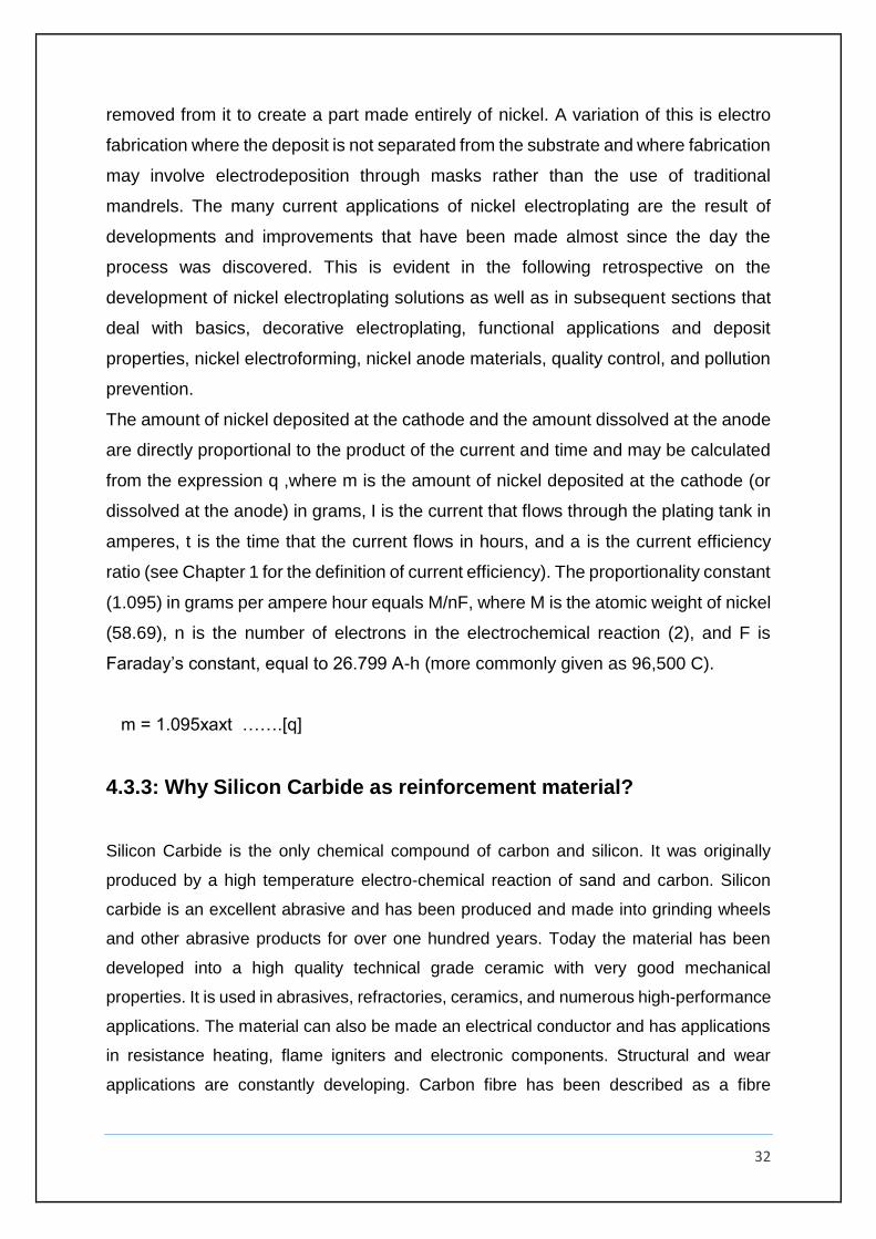
4.3.3: Why Silicon Carbide as reinforcement material?
Silicon Carbide is the only chemical compound of carbon and silicon. It was originally
produced by a high temperature electro-chemical reaction of sand and carbon. Silicon
carbide is an excellent abrasive and has been produced and made into grinding wheels
and other abrasive products for over one hundred years. Today the material has been
developed into a high quality technical grade ceramic with very good mechanical
properties. It is used in abrasives, refractories, ceramics, and numerous high-performance
applications. The material can also be made an electrical conductor and has applications
in resistance heating, flame igniters and electronic components. Structural and wear
applications are constantly developing. Carbon fibre has been described as a fibre
33
containing at least 90% carbon obtained by the controlled pyrolysis of appropriate fibres.
Carbon fibre composites are ideally suited to applications where strength, stiffness, lower
weight, and outstanding fatigue characteristics are critical requirements. They also can be
used in the occasion where high temperature, chemical inertness and high damping are
important.
Figure 16: Properties of silicon Carbide.
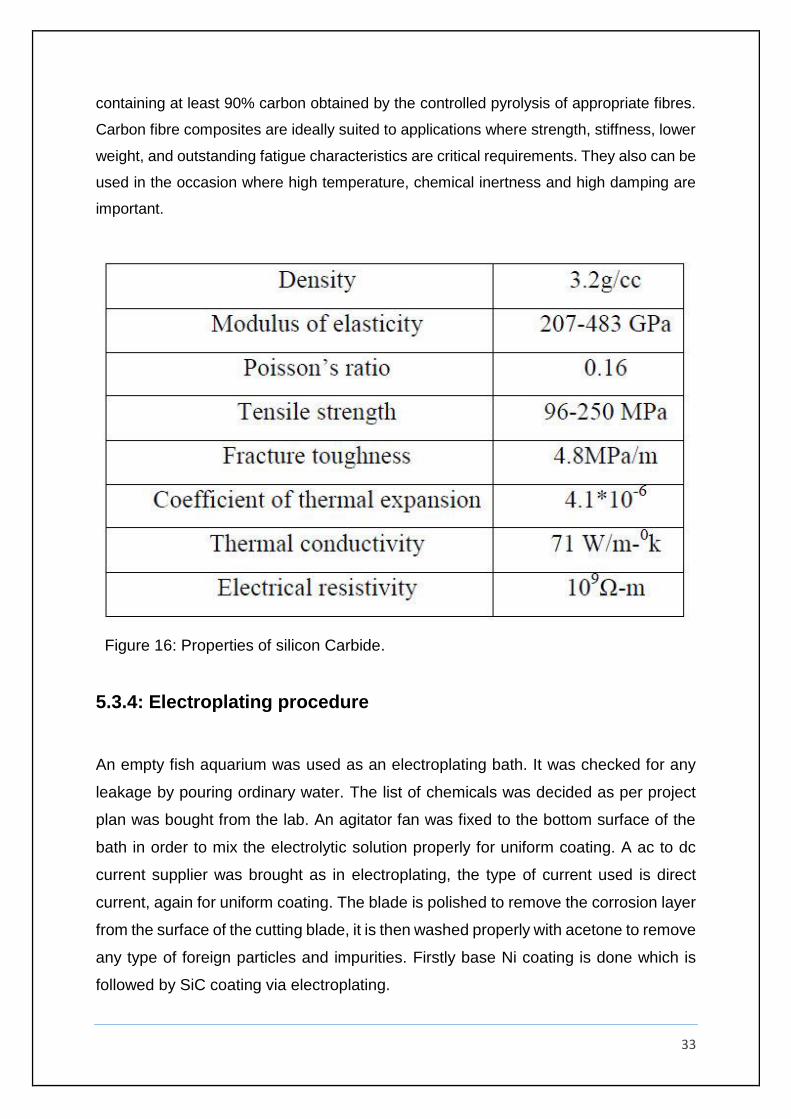
5.3.4: Electroplating procedure
An empty fish aquarium was used as an electroplating bath. It was checked for any
leakage by pouring ordinary water. The list of chemicals was decided as per project
plan was bought from the lab. An agitator fan was fixed to the bottom surface of the
bath in order to mix the electrolytic solution properly for uniform coating. A ac to dc
current supplier was brought as in electroplating, the type of current used is direct
current, again for uniform coating. The blade is polished to remove the corrosion layer
from the surface of the cutting blade, it is then washed properly with acetone to remove
any type of foreign particles and impurities. Firstly base Ni coating is done which is
followed by SiC coating via electroplating.
34
Chemicals Value
Nickel sulfamate 120 g/L
Ferrous sulphate 1 g/L
Dimethyl formamide 1 L
Boric Acid 25 g/L
BN powder 5-20 g/L
Table 2: List of chemical that is to be used.
Figure 17: The Electroplating bath
35
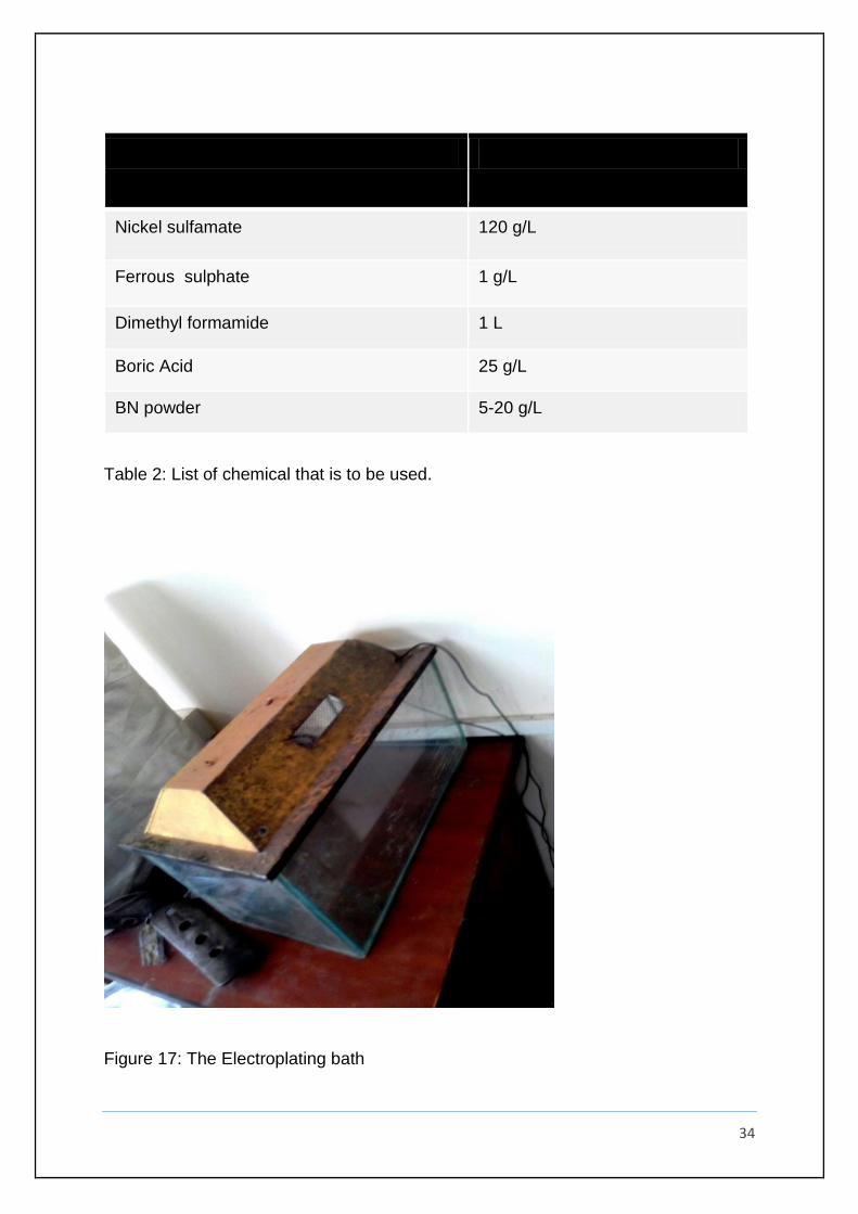
Figure 18: setting up of agitator
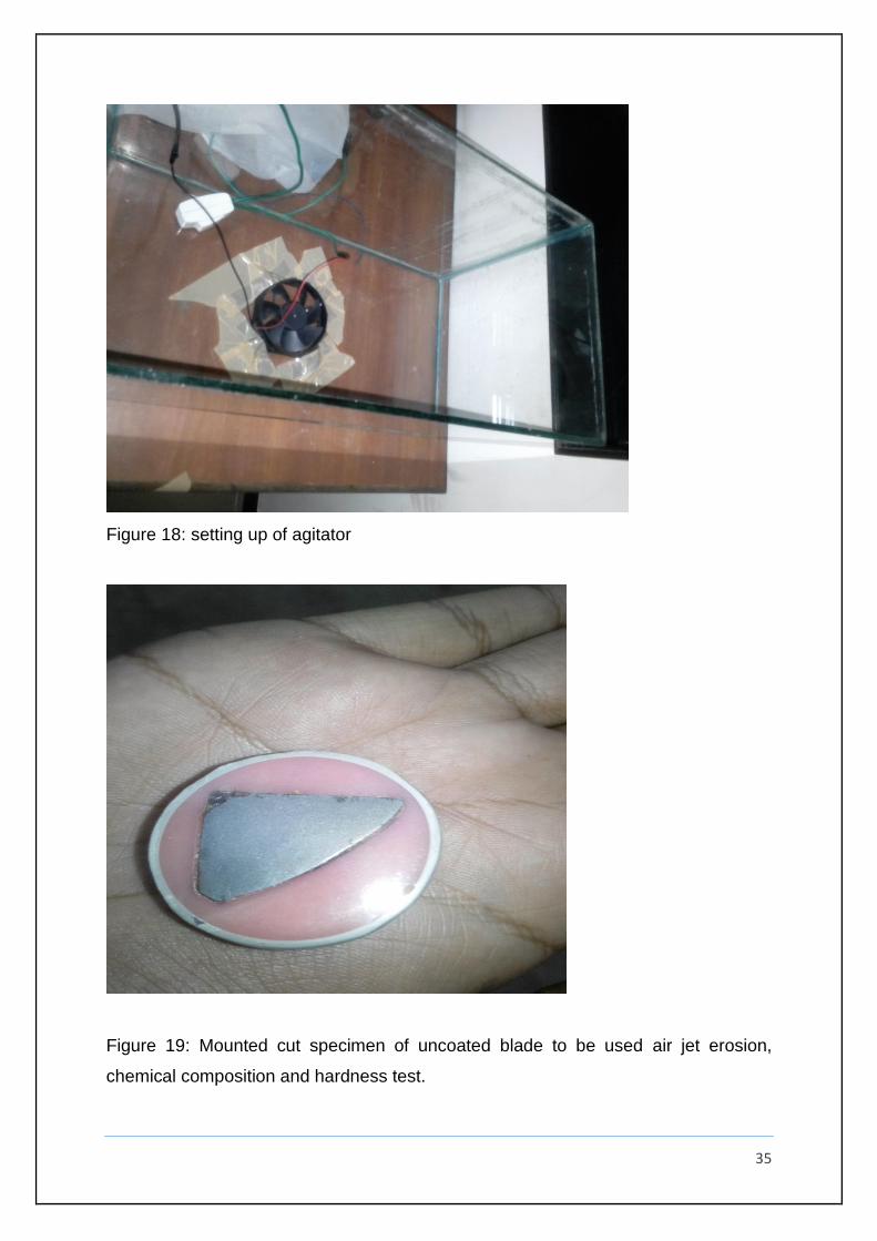
Figure 19: Mounted cut specimen of uncoated blade to be used air jet erosion,
chemical composition and hardness test.
36
Figure 20: Masking of the blade after treating it with acetone
Figure 21: preparation of required chemical mixture
37
Figure 22: electrolytic mixture poured into the bath
Figure 22: Final electroplating setup.
38
Figure 23: Picture after Ni electroplating
Figure 24: Picture after Sic composite coating.
39
4.4: Hardness test after the coating
Figure 25: Specification of the wicker’s hardness tester used
Hardness value before electroplating: 482HV
Hardness value after electroplating: 638HV
Percentage increase = 32.36
0
100
200
300
400
500
600
700
blue = before coating ; orange =after coating
hardness before and after the electroplating
Series 1 Series 2 Column1
40
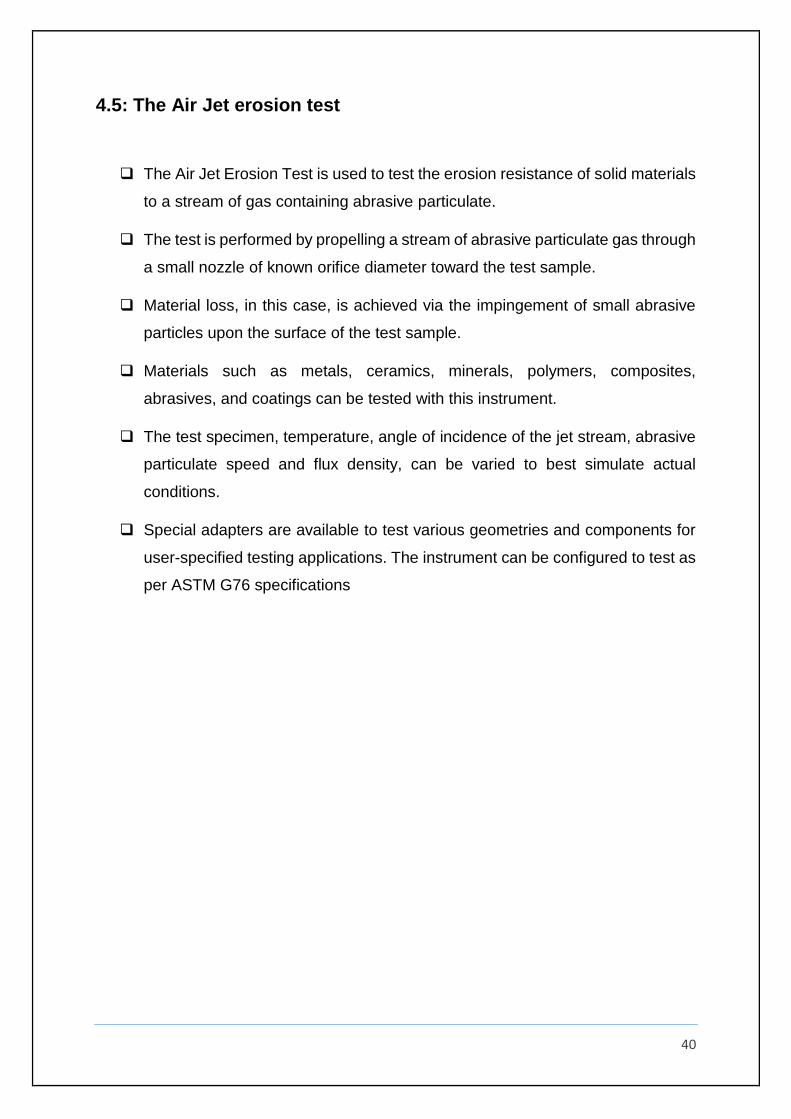
4.5: The Air Jet erosion test
The Air Jet Erosion Test is used to test the erosion resistance of solid materials
to a stream of gas containing abrasive particulate.
The test is performed by propelling a stream of abrasive particulate gas through
a small nozzle of known orifice diameter toward the test sample.
Material loss, in this case, is achieved via the impingement of small abrasive
particles upon the surface of the test sample.
Materials such as metals, ceramics, minerals, polymers, composites,
abrasives, and coatings can be tested with this instrument.
The test specimen, temperature, angle of incidence of the jet stream, abrasive
particulate speed and flux density, can be varied to best simulate actual
conditions.
Special adapters are available to test various geometries and components for
user-specified testing applications. The instrument can be configured to test as
per ASTM G76 specifications
41
Figure 26: Air jet erosion tester as per ASTM 76 standard
42
4.5.1: TEST CONDITION AND PARAMETERS
1. Erodent material: Silica sand
2. Erodent size [μm]: 300
3. Particle velocity [m/s]: 30
4. Erodent feed rate [g/m]: 2
5. Impact angle [degrees]: 90
6. Test temperature: Room temperature
7. Test time [minutes]: 5,10,15,20
8. Sample size [mm]: random
9. Nozzle inner diameter [mm]: 1.5
10. Standoff distance [mm]:50, 40, 30, 20
11. System pressure [bar] : 1.4
Note: - Weight loss of the blade specimen before and after electroplating were
recorded using a precision micro balance of accuracy 0.1 mg.
43
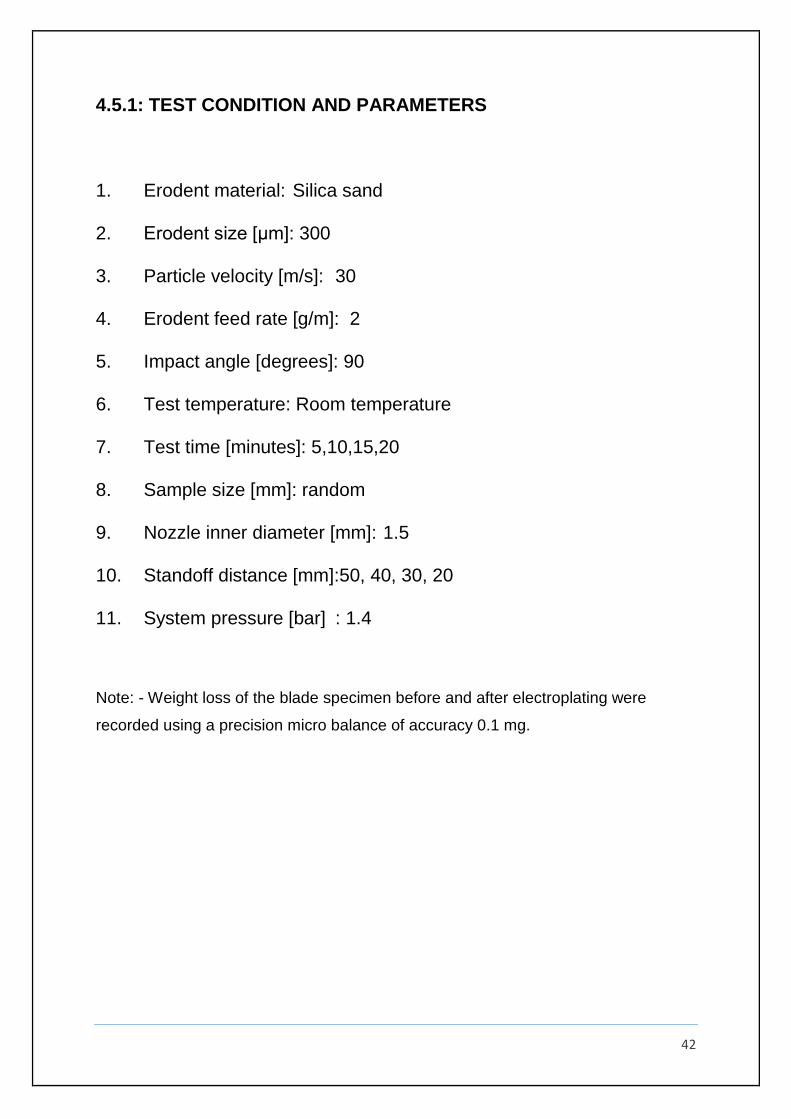
Fig 27: setup of specimen on air jet tester before testing
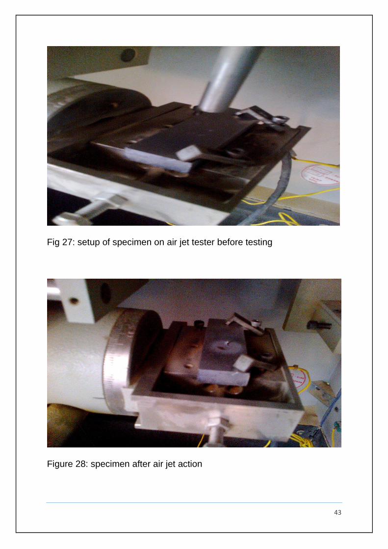
Figure 28: specimen after air jet action
44
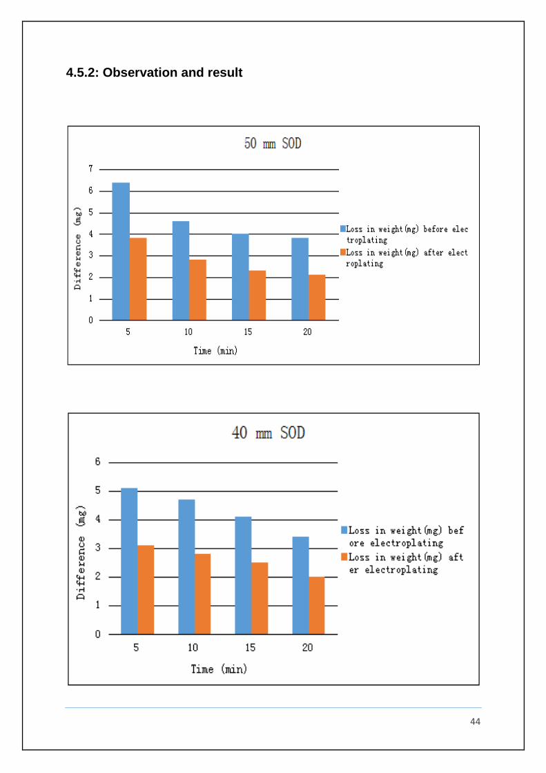
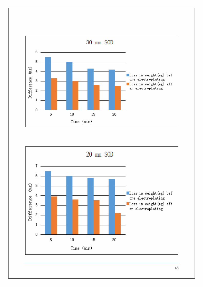
4.5.2: Observation and result
45
46
Study of air jet erosion before and after the electroplating on the blade specimen is the
last stage of our undertaken project but surely the most important one. An air jet
erosion test machine was used to assess the erosion wear behaviour. As stated earlier
the study is performed by varying two very important parameters of air jet erosion
testing i.e. duration and stand of distance of abrasive sand particles over the
specimen. We shall take up their result and discussion separately in the next section.
Looking into the various result one thing which is
very clear is that in all the case the losses after the coating is considerably less. An
average of 40% less losses is seen which proves that coating adopted by us is very
useful for combine harvester blades. The blades come contact with the components
which are eccentrically mounted over the central shaft of the harvester, hence the
distance of impact keep changing. This parameter is studied with stand of distance
which is the distance between the surface of the specimen and the tip of the nozzle. It
can be seen that with increasing time the wear losses decreases in all the cases. Since
an angle of 90 has been used there has been high losses in both the cases as with 90
degree the specimen is in direct contact with the specimen i.e the nozzle is directly
over the specimen .We can also observe a linear drop in the losses with time in both
before and after the fabrication.
Now if we make a comparison of the various stand-off
distance, it is expected that with decreasing SOD the wear loss should increase but
does not follow completely. Before the electroplating the loss was highest for 50 mmm
sod followed by 20, 30, and 40. This is because we had used the same sample for all
the sod and started with 20mm sod which gave considerable losses owing to the less
distance, so more impact. With 50 mm sod it should give the least loss but it gives the
highest loss because by this time the specimen becomes worn out and loses all its
toughness thus with higher sod also it is able to give the highest loses. Now studying
effect for before the fabrication the loses are same for 20 and 50 sod with 30 and 40
being in the intermediate range. Here also the reason can be accounted for the same
reason as stated above.
47
CHAPTER 5
CONCLUSION AND FUTURE WORKS
The project was undertaken with a mission to develop a better material for a harvester
blades. Which was achieved successfully with the use of Ni-SiC composite coating
over the blade. This was proved through hardness and air jet erosion test before and
after the electroplating. There was a 32.36% increase in the hardness and Air jet
erosion showed around 40 % less wear and erosion loses for all the cases after the
fabrication. Thus through this project we have proven the above used combination of
electroplating very much useful and superior for the harvester blades currently being
used in the agricultural sector.
The future works that can be undertaken
can be study of the above coated blade for more parameter changes in the air jet
erosion test like taking different grain size, various pressure of the air from the nozzle,
different angle of orientation. Coating combination can also be varied to check for
cheaper coating.
48
CHAPER 6
REFRENCES
[1] N. Guglielmi, J. Electrochem. Soc. 8 (119) (1972) 1009–1012.
[2] L. Benea, Composite Electrodeposition—Theory and Practice, Porto Franco,
Romania,ISBN 973 557 490 X, (1998), 173 pp.
[3] S.W. Watson, J. Electrochem. Soc. 140 (1993) 2235.
[4] G. Maurin, A. Lavanant, J. Appl. Electrochem. 25 (1995) 1113–1121.
[5] L. Benea, G. Carac, Metal. New Mater. Res. 2 (1997) 1–19.
[6] L. Benea, in: P.M. Natishan, H.S. Isaacs, M. Janik-Czachor, V.A. Macagno, P.
Marcus, M. Seo (Eds.), Proceeding volume Passivity and Its Breakdown, 1997, ISBN
1-56677-179-X.
[7] L. Benea, Mater. Manufact. Processes 14 (2) (1999) 231–242.
[8] L. Orlowskaja, N. Pereine, M. Kurtinaitiene, S. Surviliene, Surf. Coat. Technol. 111
(1999) 234–239.
[9] S.K. Kim, H.J. Yoo, Surf. Coat. Technol. 108109 (1998) 564–569.
[10] Ramesh.C.S, Harsha.R.Gudi, Nirupama Mohan and Adarsh.H, Development of
innovative Al6061-SiC composite by hybrid technique. Editors- Proceedings of STLE
Conference May 6-10, 2012, St. Louis, USA, 2012.
[11] C.S. Ramesh and Mir Safiulla, Wear behaviour of hot extruded Al6061 based
composites, Wear Vol. 263, (2007) 629-635.
[12] C.S. Ramesh and T.B. Prasad, Dry sliding friction and wear behaviour of
hypereutectic Al-Si-Carbon fibre metal matrix composite, Tribology Vol. 1 No. 4, (2007)
197-202.
[13] C.S. Ramesh, R. Keshavamurthy, S. Pramod and Praveennath G. Koppad,
Abrasive wear beha-vior of Ni–P coated Si3N4 reinforced Al6061 composites, Journal
of Materials Processing Tech-nology Vol. 211, (2011) 1423–1431.
49
[14] R.K. Uyyuru, M.K. Surappa, and S. Brusethaug, Tribological behavior of Al–Si–
SiCp compo-sites/automobile brake pad system under dry sliding conditions,
Tribology International Vol. 40, (2007) 365–373.
[15] Ranjit Bauri and M.K. Surappa, Sliding wear behavior of Al–Li–SiCp composites,
Wear Vol. 265, (2008) 1756–1766.
[16] Tamer Sinmazcelik, Sinan Fidan and Volkan Gunay, Residual mechanical
properties of car-bon/polyphenylenesulphide composites after solid particle erosion,
Materials and Design Vol. 29, (2008) 1419–1426.
[17] S.S. Mahapatra and Amar Patnaik, Study on mechanical and erosion wear
behavior of hybrid composites using Taguchi experimental design, Materials and
Design Vol. 30, (2009) 2791–2801.
[18] Brian E. MacMillin, Christopher D. Roll and Paul Funkenbusch, Erosion and
surface structure development of metal–diamond particulate composites, Wear Vol.
269, (2010) 875–883.
[19] R.J.K. Wood and A.J. Speyer, Erosion–corrosion of candidate HVOF aluminium-
based marine coatings, Wear Vol. 256, (2004) 545–556.
[20]] Z. Huang, Z.Z. Li and X. Yuan, The effect of reinforcing particles on the erosive
wear behavior of particles reinforced silicone matrix composite coating, Wear Vol. 249,
(2001) 1046–1050.
[21] A.P. Harsha and Avinash A. Thakre, Investigation on solid particle erosion
behaviour of polye-therimide and its composites, Wear Vol.262, (2007) 807–818.
[22] S.S. Mahapatra, Amar Patnaik and Alok Satapathy, Taguchi method applied to
parametric ap-praisal of erosion behaviour of GF-reinforced polyester composites,
Wear Vol. 265, (2008) 214–222.
[23] A.P. Harsha and Deepak Kumar Bhaskar, Solid particle erosion behaviour of
ferrous and non-ferrous materials and correlation of erosion data with erosion models,
Materials and Design Vol. 29, (2008) 1745–1754.

50