Embed Size (px)
Citation preview
FINAL PRESENTATIONMichigan Technological University
David Wanless4/6/2021
University Image Logo
Team Introductions
Members: John Kurburski, Jake Lehmann, Andrew Ward
Alexander Provoast
Faculty advisor: Dave Wanless
Mentors: Courtney Castelic & Cedrick Barber
Midway Summary 2/11/21• Design Objectives: Schematics Finalized
Shortly After Midway Review
• Vehicle Design: Placements of Motor and
Pump
• Fluid Power Circuit Design: Schematic
Was Not Finalized
Midway Summary 2/11/21• Selection of Hardware: Mix of Parts on
Hand, on Order, and Waiting to be
Ordered
• Results and Incorporations: Feedback
Taken from Both Review and Mentor
Consultations, Changed and Improved
Designs
Spring Objectives
• Build a Safe and Reliable Vehicle
• Finalize Hydraulic Design
• Finalize Pneumatic Circuit Design
• Fully Assemble Hydraulic and Pneumatic
Circuits
• Successfully Test All Functions of the Bike
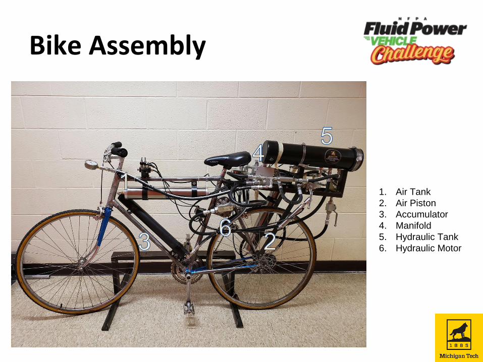
Bike Assembly
1. Air Tank
2. Air Piston
3. Accumulator
4. Manifold
5. Hydraulic Tank
6. Hydraulic Motor
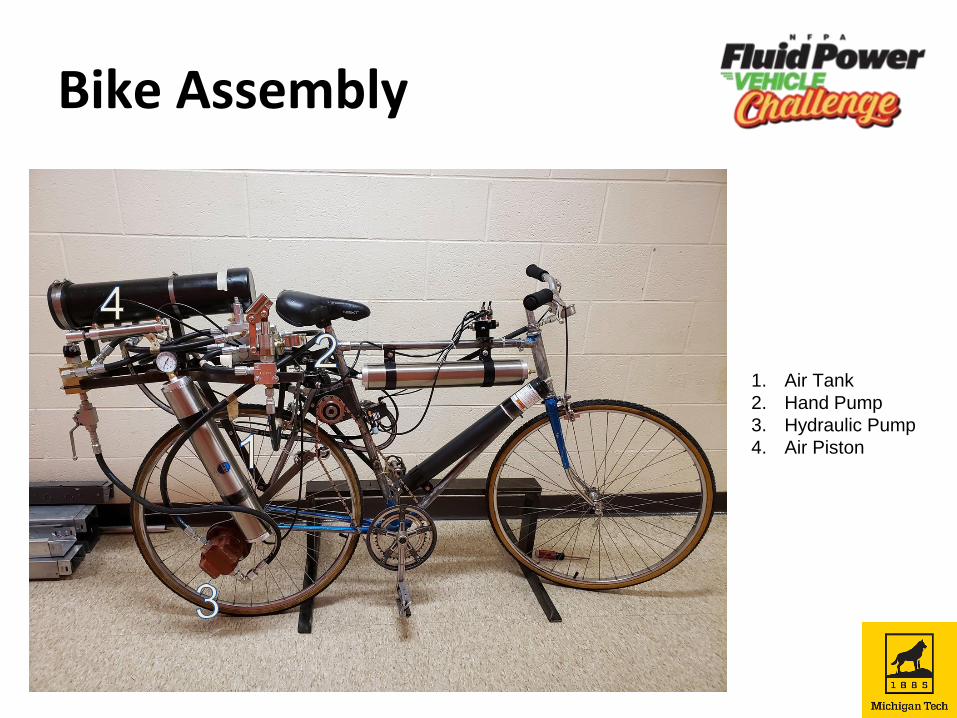
Bike Assembly
1. Air Tank
2. Hand Pump
3. Hydraulic Pump
4. Air Piston
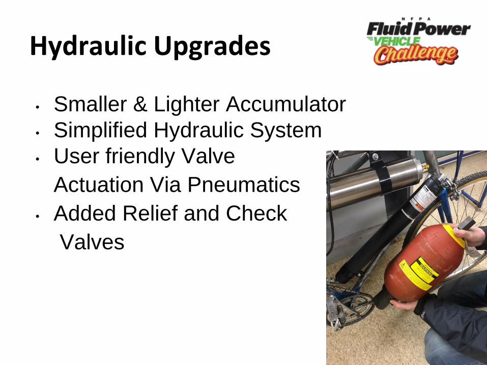
Hydraulic Upgrades
• Smaller & Lighter Accumulator
• Simplified Hydraulic System
• User friendly Valve
Actuation Via Pneumatics
• Added Relief and Check
Valves
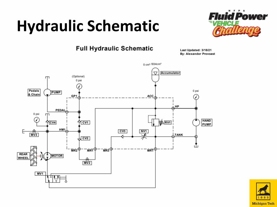
Hydraulic Schematic
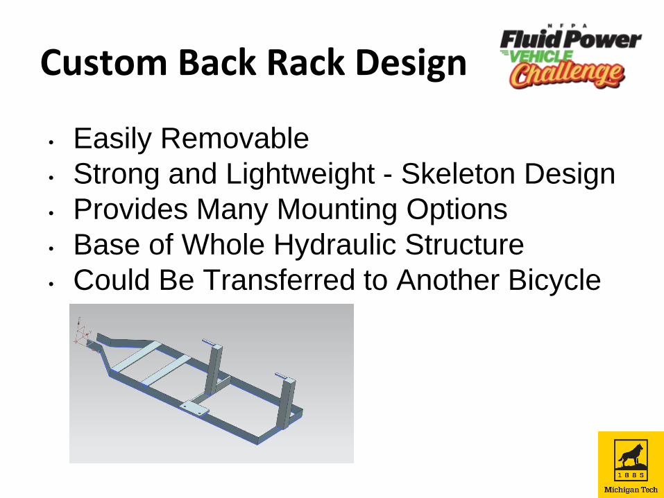
Custom Back Rack Design
• Easily Removable
• Strong and Lightweight - Skeleton Design
• Provides Many Mounting Options
• Base of Whole Hydraulic Structure
• Could Be Transferred to Another Bicycle
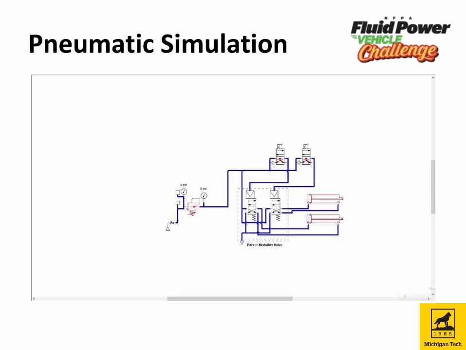
Pneumatic System Updates
• Finalized Pneumatic Layout
• Spec’d Pneumatic Cylinders
• Ordered and Installed Parts
• Performed System Test
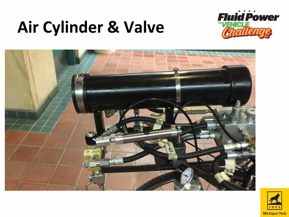
Valve Actuation
• Use of air cylinders to open and close
hydraulic valves
• Switches Near Handlebar for Easy
Actuation
• Allows Hydraulics and Pneumatics to
Work Together
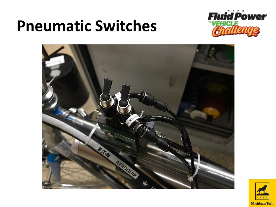
Pneumatic Switches
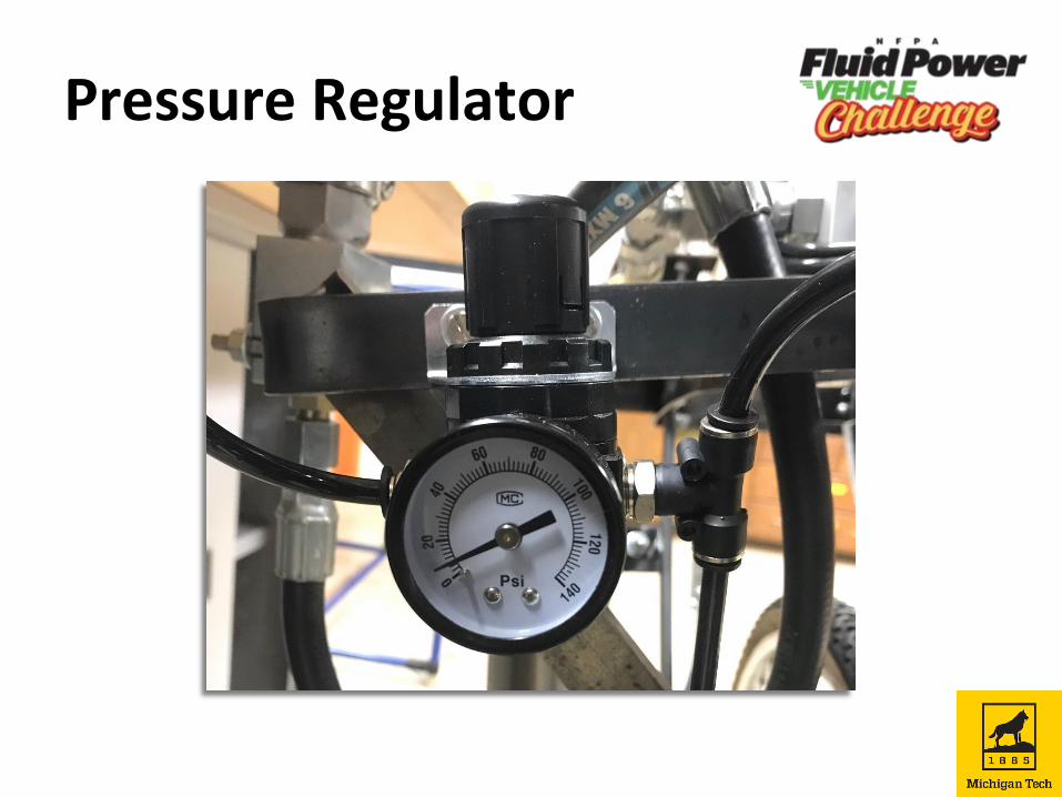
Pressure Regulator
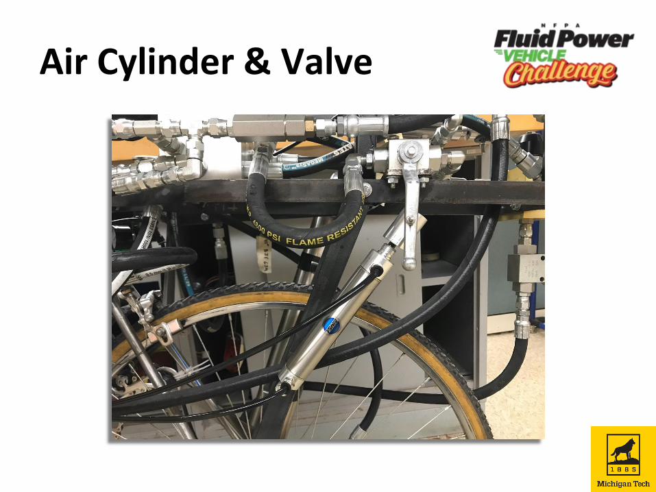
Air Cylinder & Valve
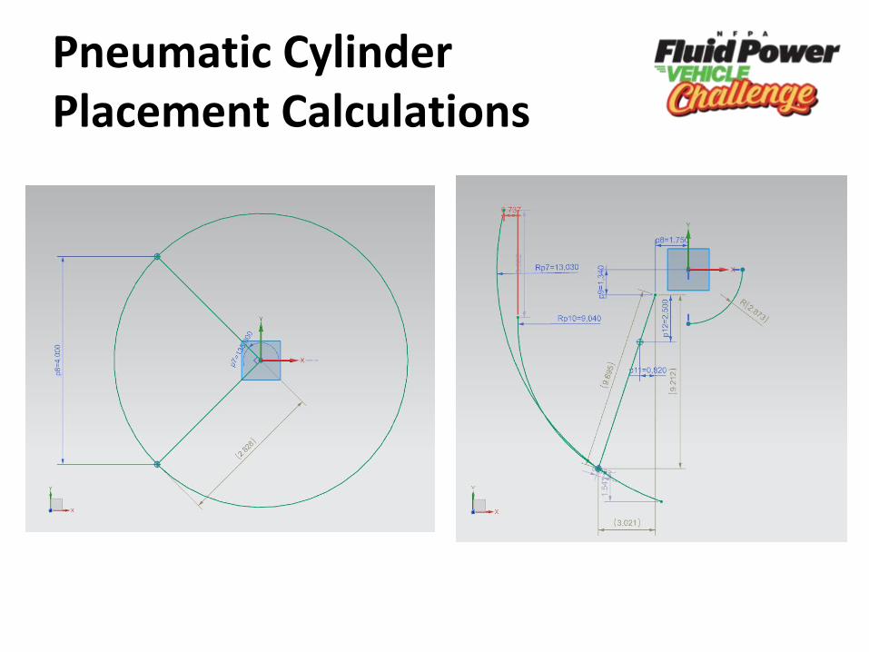
Pneumatic Cylinder Placement Calculations
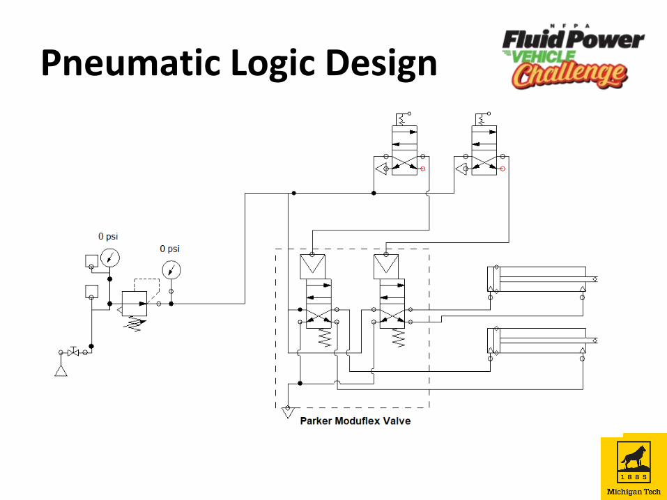
Pneumatic Logic Design
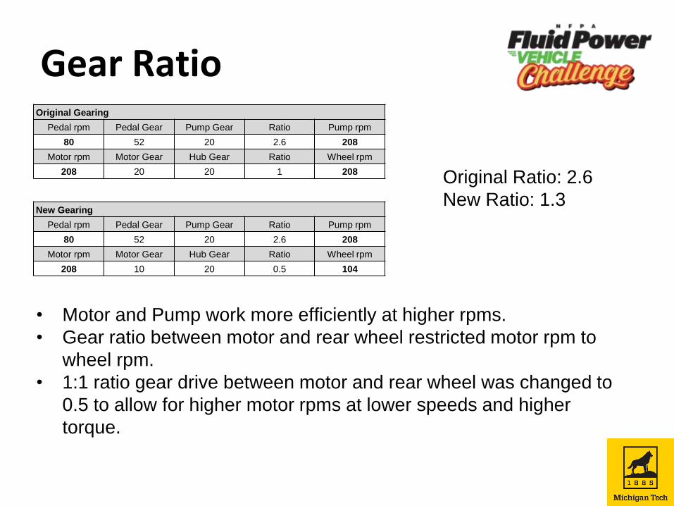
Gear Ratio
• Motor and Pump work more efficiently at higher rpms.
• Gear ratio between motor and rear wheel restricted motor rpm to
wheel rpm.
• 1:1 ratio gear drive between motor and rear wheel was changed to
0.5 to allow for higher motor rpms at lower speeds and higher
torque.
Original Gearing
Pedal rpm Pedal Gear Pump Gear Ratio Pump rpm
80 52 20 2.6 208
Motor rpm Motor Gear Hub Gear Ratio Wheel rpm
208 20 20 1 208
New Gearing
Pedal rpm Pedal Gear Pump Gear Ratio Pump rpm
80 52 20 2.6 208
Motor rpm Motor Gear Hub Gear Ratio Wheel rpm
208 10 20 0.5 104
Original Ratio: 2.6
New Ratio: 1.3
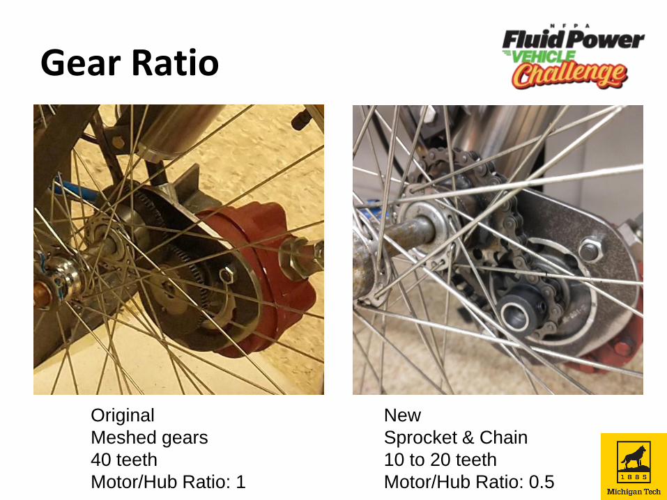
Gear Ratio
Original
Meshed gears
40 teeth
Motor/Hub Ratio: 1
New
Sprocket & Chain
10 to 20 teeth
Motor/Hub Ratio: 0.5
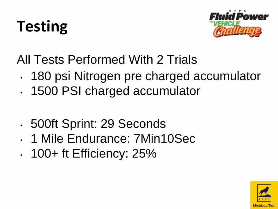
Testing
All Tests Performed With 2 Trials
• 180 psi Nitrogen pre charged accumulator
• 1500 PSI charged accumulator
• 500ft Sprint: 29 Seconds
• 1 Mile Endurance: 7Min10Sec
• 100+ ft Efficiency: 25%
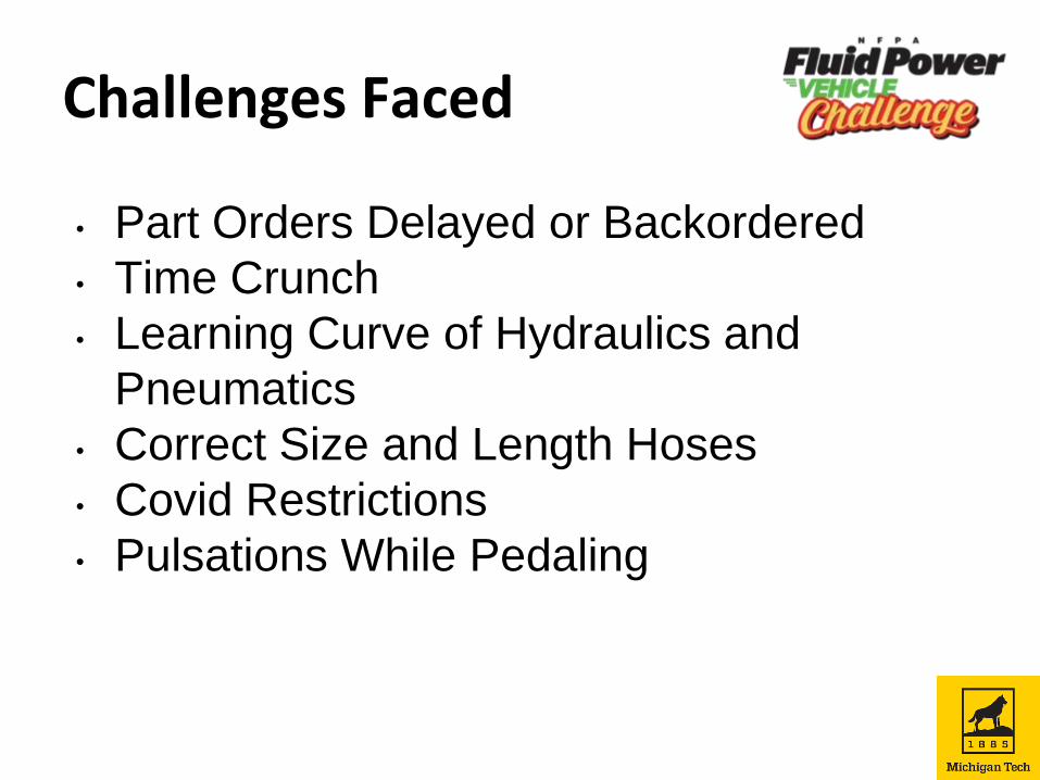
Challenges Faced
• Part Orders Delayed or Backordered
• Time Crunch
• Learning Curve of Hydraulics and
Pneumatics
• Correct Size and Length Hoses
• Covid Restrictions
• Pulsations While Pedaling
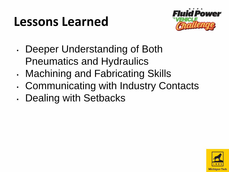
Lessons Learned
• Deeper Understanding of Both
Pneumatics and Hydraulics
• Machining and Fabricating Skills
• Communicating with Industry Contacts
• Dealing with Setbacks

Thank You for Your Time
Are There Any Questions?