Embed Size (px)
Citation preview
UNIT – 3
Flexure and Serviceability Limit State
Beam
A structural member that support transverse (Perpendicular to the axis of the member)
load is called a beam. Beams are subjected to bending moment and shear force. Beams are
also known as flexural or bending members. In a beam one of the dimensions is very large
compared to the other two dimensions. Beams may be of the following types:
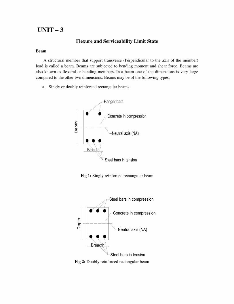
a. Singly or doubly reinforced rectangular beams
Fig 1: Singly reinforced rectangular beam
Fig 2: Doubly reinforced rectangular beam
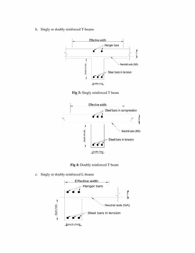
b. Singly or doubly reinforced T-beams
Fig 3: Singly reinforced T beam
Fig 4: Doubly reinforced T beam
c. Singly or doubly reinforced L-beams
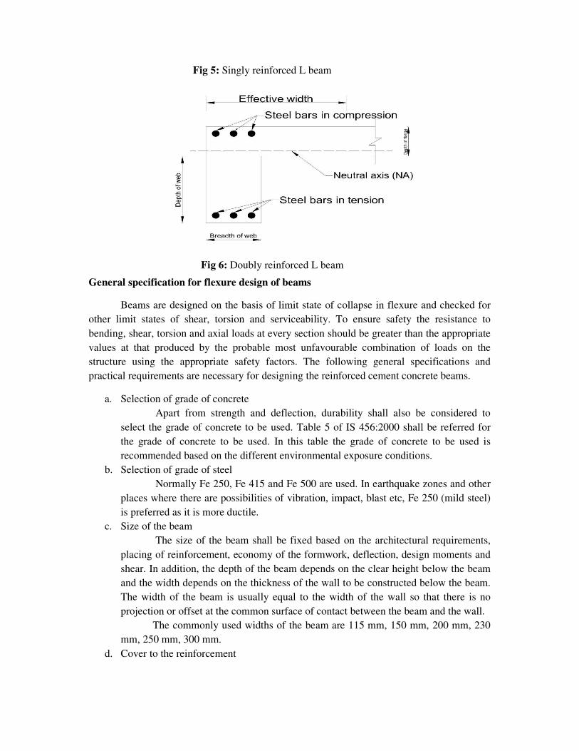
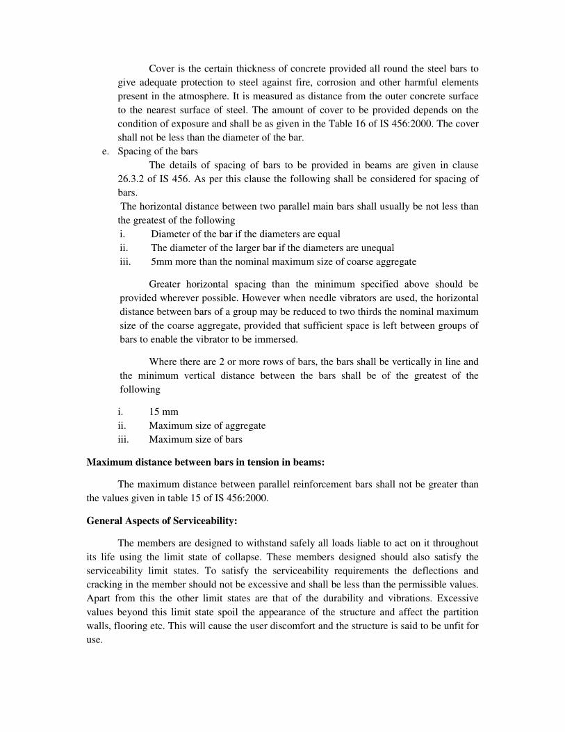
Fig 5: Singly reinforced L beam
Fig 6: Doubly reinforced L beam
General specification for flexure design of beams
Beams are designed on the basis of limit state of collapse in flexure and checked for
other limit states of shear, torsion and serviceability. To ensure safety the resistance to
bending, shear, torsion and axial loads at every section should be greater than the appropriate
values at that produced by the probable most unfavourable combination of loads on the
structure using the appropriate safety factors. The following general specifications and
practical requirements are necessary for designing the reinforced cement concrete beams.
a. Selection of grade of concrete
Apart from strength and deflection, durability shall also be considered to
select the grade of concrete to be used. Table 5 of IS 456:2000 shall be referred for
the grade of concrete to be used. In this table the grade of concrete to be used is
recommended based on the different environmental exposure conditions.
b. Selection of grade of steel
Normally Fe 250, Fe 415 and Fe 500 are used. In earthquake zones and other
places where there are possibilities of vibration, impact, blast etc, Fe 250 (mild steel)
is preferred as it is more ductile.
c. Size of the beam
The size of the beam shall be fixed based on the architectural requirements,
placing of reinforcement, economy of the formwork, deflection, design moments and
shear. In addition, the depth of the beam depends on the clear height below the beam
and the width depends on the thickness of the wall to be constructed below the beam.
The width of the beam is usually equal to the width of the wall so that there is no
projection or offset at the common surface of contact between the beam and the wall.
The commonly used widths of the beam are 115 mm, 150 mm, 200 mm, 230
mm, 250 mm, 300 mm.
d. Cover to the reinforcement
Cover is the certain thickness of concrete provided all round the steel bars to
give adequate protection to steel against fire, corrosion and other harmful elements
present in the atmosphere. It is measured as distance from the outer concrete surface
to the nearest surface of steel. The amount of cover to be provided depends on the
condition of exposure and shall be as given in the Table 16 of IS 456:2000. The cover
shall not be less than the diameter of the bar.
e. Spacing of the bars
The details of spacing of bars to be provided in beams are given in clause
26.3.2 of IS 456. As per this clause the following shall be considered for spacing of
bars.
The horizontal distance between two parallel main bars shall usually be not less than
the greatest of the following
i. Diameter of the bar if the diameters are equal
ii. The diameter of the larger bar if the diameters are unequal
iii. 5mm more than the nominal maximum size of coarse aggregate
Greater horizontal spacing than the minimum specified above should be
provided wherever possible. However when needle vibrators are used, the horizontal
distance between bars of a group may be reduced to two thirds the nominal maximum
size of the coarse aggregate, provided that sufficient space is left between groups of
bars to enable the vibrator to be immersed.
Where there are 2 or more rows of bars, the bars shall be vertically in line and
the minimum vertical distance between the bars shall be of the greatest of the
following
i. 15 mm
ii. Maximum size of aggregate
iii. Maximum size of bars
Maximum distance between bars in tension in beams:
The maximum distance between parallel reinforcement bars shall not be greater than
the values given in table 15 of IS 456:2000.
General Aspects of Serviceability:
The members are designed to withstand safely all loads liable to act on it throughout
its life using the limit state of collapse. These members designed should also satisfy the
serviceability limit states. To satisfy the serviceability requirements the deflections and
cracking in the member should not be excessive and shall be less than the permissible values.
Apart from this the other limit states are that of the durability and vibrations. Excessive
values beyond this limit state spoil the appearance of the structure and affect the partition
walls, flooring etc. This will cause the user discomfort and the structure is said to be unfit for
use.
The different load combinations and the
used for the limit state of serviceability are given in Table 18 of IS 456:2000.
Limit state of serviceability for flexural members:
Deflection
The check for deflection is done through the following two
456:2000 (Refer clause 42.1)
1 Empirical Method
In this method, the deflection criteria of the member is said to be satisfied
when the actual value of span to depth ratio of the member is less than the
permissible values. The IS code
are as given below
a. Choosing the basic values of span to effective depth ratios (l/d) from the
following, depending on the type of beam
1. Cantilever = 8
2. Simply supported = 20
3. Continuous
b. Modify the value of basic span to depth ratio to get the allowable span to depth
ratio.
Allowable l/d = Basic l/d x M
Where, Mt = Modification factor obtained from fig 4 IS 456:2000. It depends
on the area of tension
Mc = Modification factor obtained from fig 5 IS 456:2000. This depends on
the area of compression steel used.
Mf = Reduction factor got from fig 6 of IS 456:2000
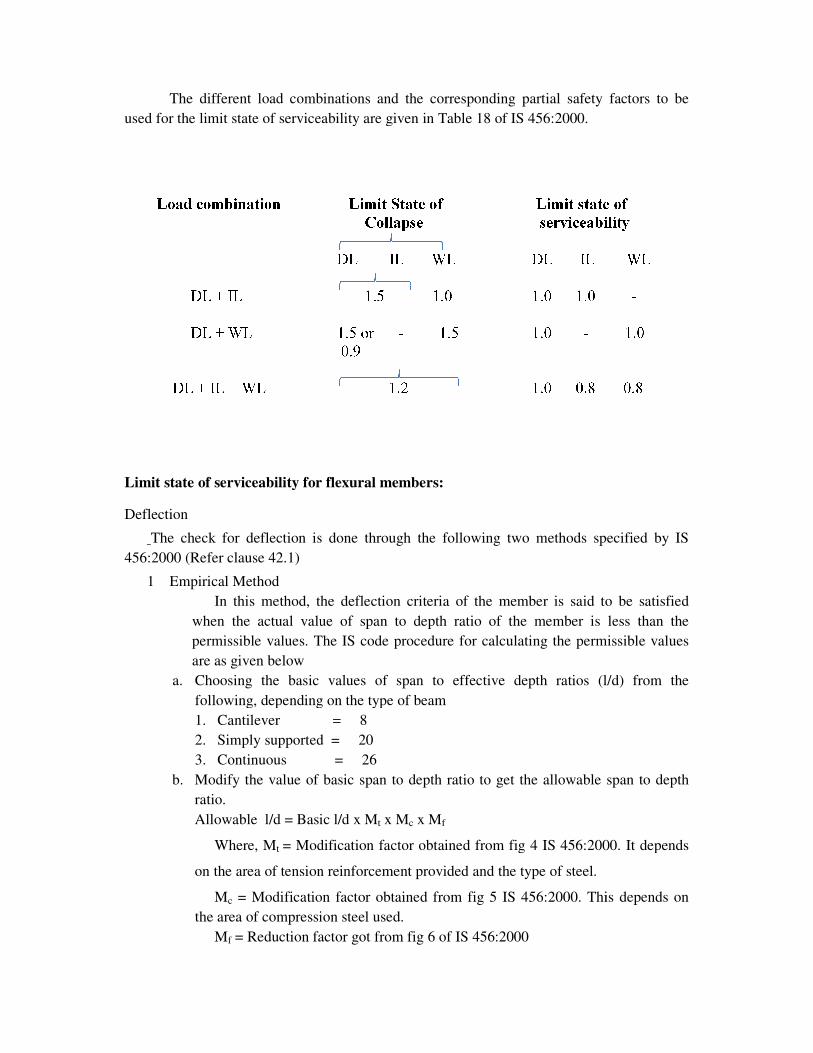
The different load combinations and the corresponding partial safety factors to be
used for the limit state of serviceability are given in Table 18 of IS 456:2000.
Limit state of serviceability for flexural members:
The check for deflection is done through the following two methods specified by IS
In this method, the deflection criteria of the member is said to be satisfied
when the actual value of span to depth ratio of the member is less than the
permissible values. The IS code procedure for calculating the permissible values
Choosing the basic values of span to effective depth ratios (l/d) from the
following, depending on the type of beam
Cantilever = 8
Simply supported = 20
= 26
the value of basic span to depth ratio to get the allowable span to depth
Allowable l/d = Basic l/d x Mt x Mc x Mf
= Modification factor obtained from fig 4 IS 456:2000. It depends
on the area of tension reinforcement provided and the type of steel.
= Modification factor obtained from fig 5 IS 456:2000. This depends on
the area of compression steel used.
= Reduction factor got from fig 6 of IS 456:2000
corresponding partial safety factors to be
methods specified by IS
In this method, the deflection criteria of the member is said to be satisfied
when the actual value of span to depth ratio of the member is less than the
the permissible values
Choosing the basic values of span to effective depth ratios (l/d) from the
the value of basic span to depth ratio to get the allowable span to depth
= Modification factor obtained from fig 4 IS 456:2000. It depends
= Modification factor obtained from fig 5 IS 456:2000. This depends on
Note: The basic values of l/d mentioned above is valid upto spans of 10m. The basic values
are multiplied by 10 / span in meters except for cantilever. For cantilevers whose span
exceeds 10 m the theoretical method shall be used.
2 Theoretical method of checking deflection
The actual deflections of the members are calculated as per procedure given in
annexure ‘C’ of IS 456:2000. This deflection value shall be limited to the
following
i. The final deflection due to all loads including the effects of temperature, creep and
shrinkage shall not exceed span / 250.
ii. The deflection including the effects of temperature, creep and shrinkage occurring
after erection of partitions and the application of finishes shall not exceed
span/350 or 20 mm whichever is less.
Cracking in structural members
Cracking of concrete occurs whenever the tensile stress developed is greater than the
tensile strength of concrete. This happens due to large values of the following:
1. Flexural tensile stress because of excessive bending under the applied load
2. Diagonal tension due to shear and torsion
3. Direct tensile stress under applied loads (for example hoop tension in a circular
tank)
4. Lateral tensile strains accompanying high axis compressive strains due to
Poisson’s effect (as in a compression test)
5. Settlement of supports
In addition to the above reasons, cracking also occurs because of
1. Restraint against volume changes due to shrinkage, temperature creep and
chemical effects.
2. Bond and anchorage failures
Cracking spoils the aesthetics of the structure and also adversely affect the durability
of the structure. Presence of wide cracks exposes the reinforcement to the atmosphere due to
which the reinforcements get corroded causing the deterioration of concrete. In some cases,
such as liquid retaining structures and pressure vessels cracks affects the basic functional
requirement itself (such as water tightness in water tank).
Permissible crack width
The permissible crack width in structural concrete members depends on the type of
structure and the exposure conditions. The permissible values are prescribed in clause 35.3.2
IS 456:2000 and are shown in table below
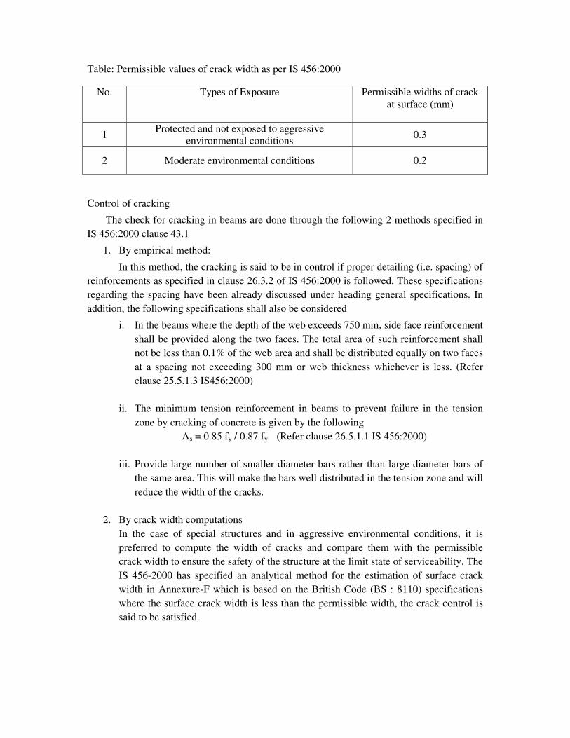
Table: Permissible values of crack width as per IS 456:2000
No. Types of Exposure Permissible widths of crack
at surface (mm)
1 Protected and not exposed to aggressive
environmental conditions 0.3
2 Moderate environmental conditions 0.2
Control of cracking
The check for cracking in beams are done through the following 2 methods specified in
IS 456:2000 clause 43.1
1. By empirical method:
In this method, the cracking is said to be in control if proper detailing (i.e. spacing) of
reinforcements as specified in clause 26.3.2 of IS 456:2000 is followed. These specifications
regarding the spacing have been already discussed under heading general specifications. In
addition, the following specifications shall also be considered
i. In the beams where the depth of the web exceeds 750 mm, side face reinforcement
shall be provided along the two faces. The total area of such reinforcement shall
not be less than 0.1% of the web area and shall be distributed equally on two faces
at a spacing not exceeding 300 mm or web thickness whichever is less. (Refer
clause 25.5.1.3 IS456:2000)
ii. The minimum tension reinforcement in beams to prevent failure in the tension
zone by cracking of concrete is given by the following
As = 0.85 fy / 0.87 fy (Refer clause 26.5.1.1 IS 456:2000)
iii. Provide large number of smaller diameter bars rather than large diameter bars of
the same area. This will make the bars well distributed in the tension zone and will
reduce the width of the cracks.
2. By crack width computations
In the case of special structures and in aggressive environmental conditions, it is
preferred to compute the width of cracks and compare them with the permissible
crack width to ensure the safety of the structure at the limit state of serviceability. The
IS 456-2000 has specified an analytical method for the estimation of surface crack
width in Annexure-F which is based on the British Code (BS : 8110) specifications
where the surface crack width is less than the permissible width, the crack control is
said to be satisfied.
Problems:
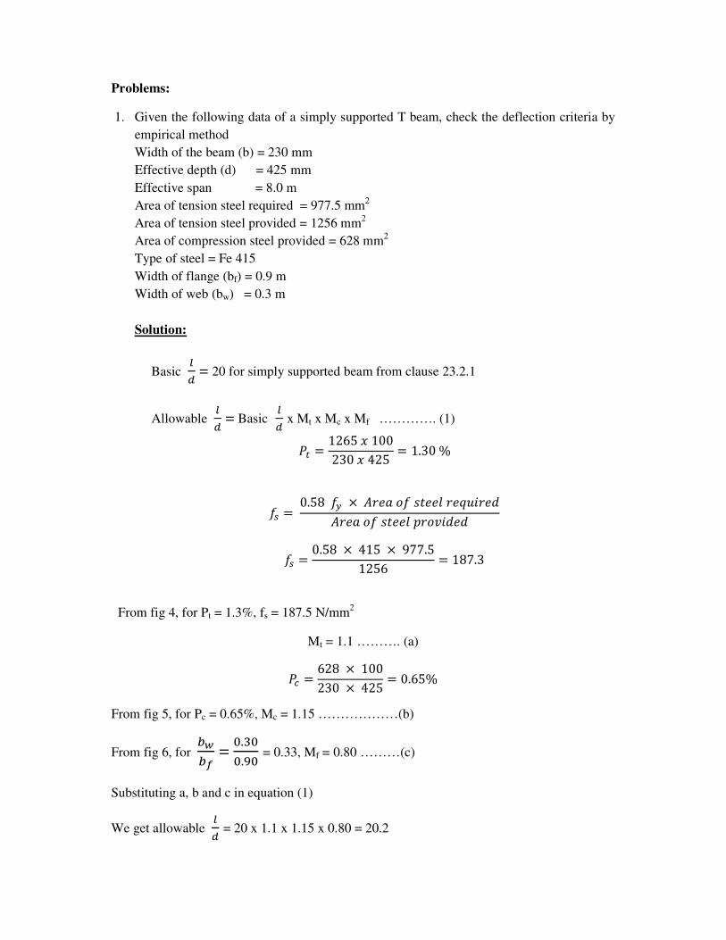
1. Given the following data of a simply supported T beam, check the deflection criteria by
empirical method
Width of the beam (b) = 230 mm
Effective depth (d) = 425 mm
Effective span = 8.0 m
Area of tension steel required = 977.5 mm2
Area of tension steel provided = 1256 mm2
Area of compression steel provided = 628 mm2
Type of steel = Fe 415
Width of flange (bf) = 0.9 m
Width of web (bw) = 0.3 m
Solution:
Basic �� = 20 for simply supported beam from clause 23.2.1
Allowable �� = Basic
�� x Mt x Mc x Mf …………. (1)
�� = 1265�100230�425 = 1.30%
�� = 0.58�� × ��������������� ��!�����������"��# !�!
�� = 0.58 × 415 × 977.51256 = 187.3
From fig 4, for Pt = 1.3%, fs = 187.5 N/mm2
Mt = 1.1 ………. (a)
�& = 628 × 100230 × 425 = 0.65%
From fig 5, for Pc = 0.65%, Mc = 1.15 ………………(b)
From fig 6, for '(') =
*.+**.,* = 0.33, Mf = 0.80 ………(c)
Substituting a, b and c in equation (1)
We get allowable �� = 20 x 1.1 x 1.15 x 0.80 = 20.2
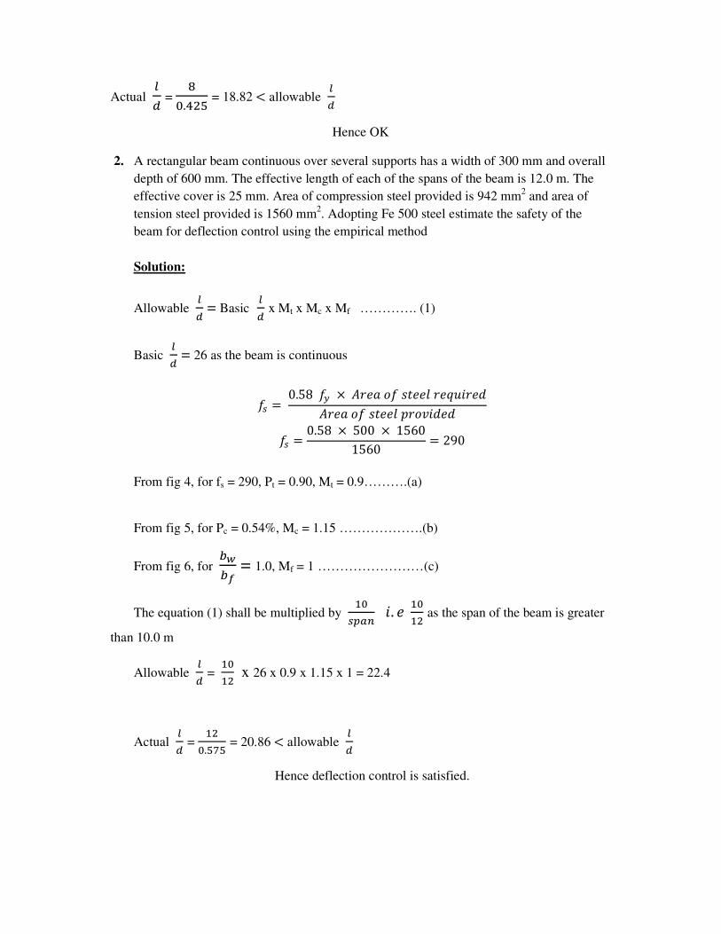
Actual �� =
-*../0 = 18.82 < allowable
��
Hence OK
2. A rectangular beam continuous over several supports has a width of 300 mm and overall
depth of 600 mm. The effective length of each of the spans of the beam is 12.0 m. The
effective cover is 25 mm. Area of compression steel provided is 942 mm2 and area of
tension steel provided is 1560 mm2. Adopting Fe 500 steel estimate the safety of the
beam for deflection control using the empirical method
Solution:
Allowable �� = Basic
�� x Mt x Mc x Mf …………. (1)
Basic �� = 26 as the beam is continuous
�� = 0.58�� × ��������������� ��!�����������"��# !�!
�� = 0.58 × 500 × 15601560 = 290
From fig 4, for fs = 290, Pt = 0.90, Mt = 0.9……….(a)
From fig 5, for Pc = 0.54%, Mc = 1.15 ……………….(b)
From fig 6, for '(') = 1.0, Mf = 1 ……………………(c)
The equation (1) shall be multiplied by 2*
�345 . � 2*2/ as the span of the beam is greater
than 10.0 m
Allowable �� =
2*2/ x 26 x 0.9 x 1.15 x 1 = 22.4
Actual �� =
2/*.060 = 20.86 < allowable
��
Hence deflection control is satisfied.
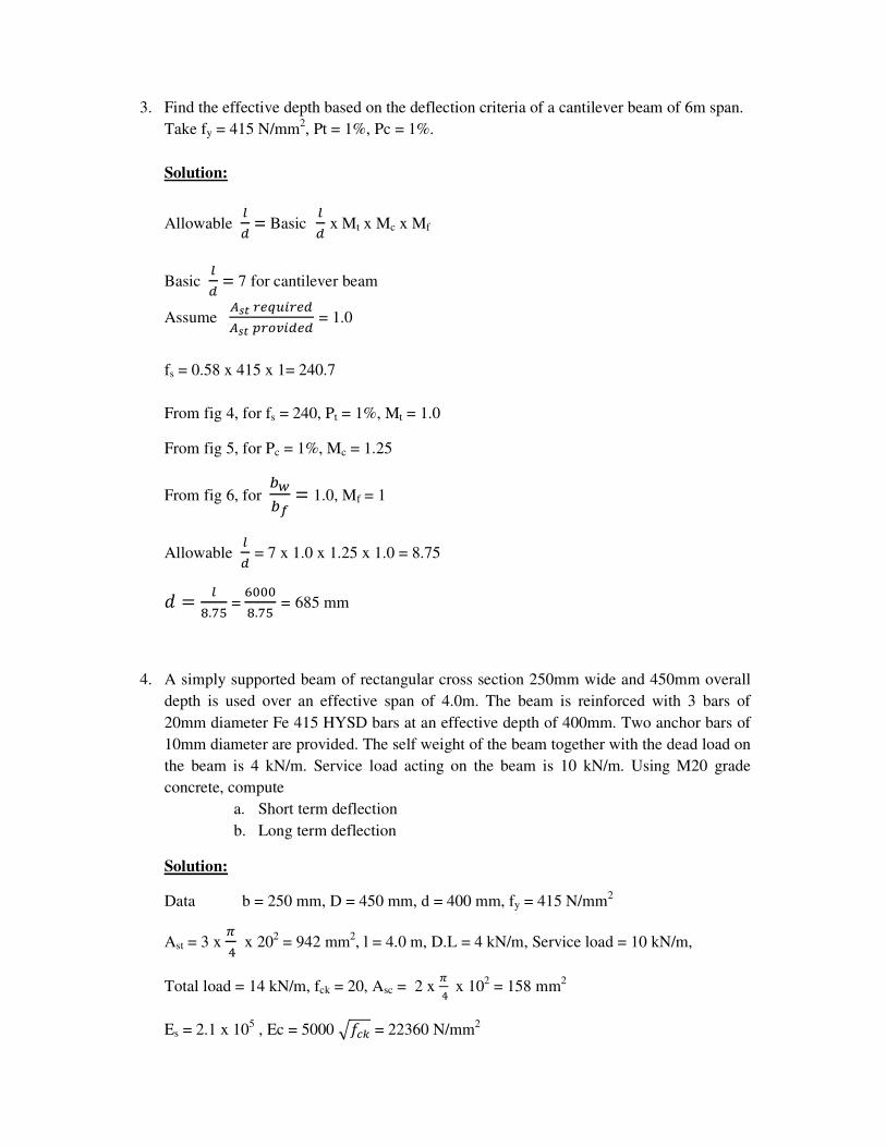
3. Find the effective depth based on the deflection criteria of a cantilever beam of 6m span.
Take fy = 415 N/mm2, Pt = 1%, Pc = 1%.
Solution:
Allowable �� = Basic
�� x Mt x Mc x Mf
Basic �� = 7 for cantilever beam
Assume 789:;<=>:;�7893:?@>�;� = 1.0
fs = 0.58 x 415 x 1= 240.7
From fig 4, for fs = 240, Pt = 1%, Mt = 1.0
From fig 5, for Pc = 1%, Mc = 1.25
From fig 6, for '(') = 1.0, Mf = 1
Allowable �� = 7 x 1.0 x 1.25 x 1.0 = 8.75
! = �-.60 =
A***-.60 = 685 mm
4. A simply supported beam of rectangular cross section 250mm wide and 450mm overall
depth is used over an effective span of 4.0m. The beam is reinforced with 3 bars of
20mm diameter Fe 415 HYSD bars at an effective depth of 400mm. Two anchor bars of
10mm diameter are provided. The self weight of the beam together with the dead load on
the beam is 4 kN/m. Service load acting on the beam is 10 kN/m. Using M20 grade
concrete, compute
a. Short term deflection
b. Long term deflection
Solution:
Data b = 250 mm, D = 450 mm, d = 400 mm, fy = 415 N/mm2
Ast = 3 x B.x 20
2 = 942 mm
2, l = 4.0 m, D.L = 4 kN/m, Service load = 10 kN/m,
Total load = 14 kN/m, fck = 20, Asc = 2 x B.x 10
2 = 158 mm
2
Es = 2.1 x 10⁵ , Ec = 5000 C�&D = 22360 N/mm
2
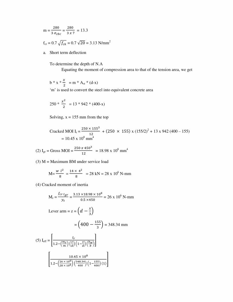
m = /-*
+EFGF = /-*
+H6= 13.3
fcr = 0.7 C�&D = 0.7 √20 = 3.13 N/mm2
a. Short term deflection
To determine the depth of N.A
Equating the moment of compression area to that of the tension area, we get
b * x * H/ = m * Ast * (d-x)
‘m’ is used to convert the steel into equivalent concrete area
250 * HJ/ = 13 * 942 * (400-x)
Solving, x = 155 mm from the top
Cracked MOI Ir = /0*×200K
2/ + L250 × 155M x (155/2)2 + 13 x 942 (400 – 155)
= 10.45 x 108 mm
4
(2) Igr = Gross MOI = /0*H.0*K
2/ = 18.98 x 108 mm
4
(3) M = Maximum BM under service load
M= N�J
- = 2.×.J
- = 28 kN = 28 x 106 N-mm
(4) Cracked moment of inertia
Mr = OFPQRP�9 =
+.2+×2-.,-×2*S*.0×.0* = 26 x 10
6 N-mm
Lever arm = z = T! − H+V
= T400 − 200+ V = 348.34 mm
(5) Ieff = W XP2./YTZPZ VT[\VT2Y]\VTG(G V^
_ 2*..0×2*S2./Y`Ja×bca
JS×bcadTKeS.Keecc VT2YbffeccVL2Mg
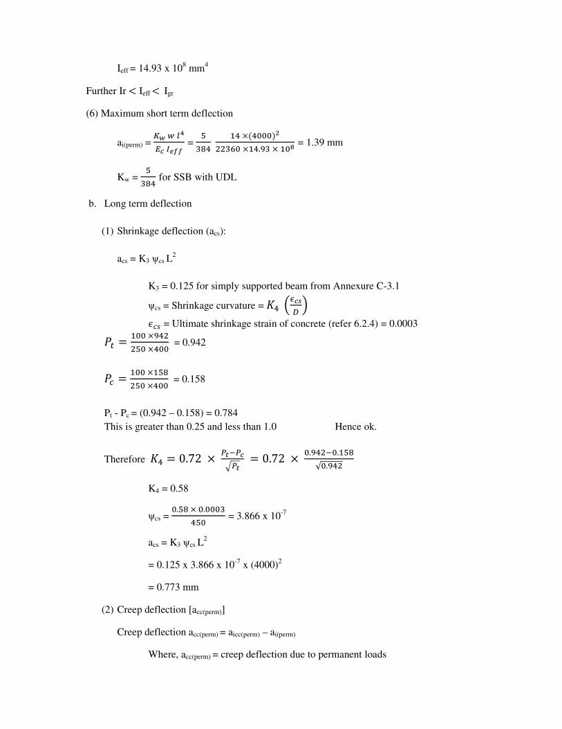
Ieff = 14.93 x 108 mm
4
Further Ir < Ieff < Igr
(6) Maximum short term deflection
ai(perm) = h(N�eiFXj)) =
0+-. 2.×L.***MJ
//+A*×2..,+×2*S = 1.39 mm
Kw = 0
+-. for SSB with UDL
b. Long term deflection
(1) Shrinkage deflection (acs):
acs = K3 ψcs L2
K3 = 0.125 for simply supported beam from Annexure C-3.1
ψcs = Shrinkage curvature = k. TlF8m V
n&� = Ultimate shrinkage strain of concrete (refer 6.2.4) = 0.0003
�� = 2**×,.//0*×.** = 0.942
�& = 2**×20-/0*×.** = 0.158
Pt - Pc = (0.942 – 0.158) = 0.784
This is greater than 0.25 and less than 1.0 Hence ok.
Therefore k. = 0.72 ×o9YoFCo9 = 0.72 ×*.,./Y*.20-√*.,./
K4 = 0.58
ψcs = *.0-×*.***+
.0* = 3.866 x 10⁻⁷
acs = K3 ψcs L2
= 0.125 x 3.866 x 10-7
x (4000)2
= 0.773 mm
(2) Creep deflection [acc(perm)]
Creep deflection acc(perm) = aicc(perm) – ai(perm)
Where, acc(perm) = creep deflection due to permanent loads
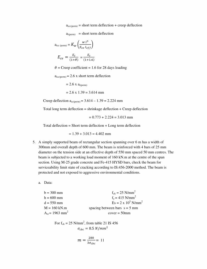
aicc(perm) = short term deflection + creep deflection
ai(perm) = short term deflection
aicc (perm) = kN ` N�KiFjXj))d
p&; = iFL2qrM = iFL2q2.AM
s = Creep coefficient = 1.6 for 28 days loading
aicc(perm) = 2.6 x short term deflection
= 2.6 x ai(perm)
= 2.6 x 1.39 = 3.614 mm
Creep deflection acc(perm) = 3.614 – 1.39 = 2.224 mm
Total long term deflection = shrinkage deflection + Creep deflection
= 0.773 + 2.224 = 3.013 mm
Total deflection = Short term deflection + Long term deflection
= 1.39 + 3.013 = 4.402 mm
5. A simply supported beam of rectangular section spanning over 6 m has a width of
300mm and overall depth of 600 mm. The beam is reinforced with 4 bars of 25 mm
diameter on the tension side at an effective depth of 550 mm spaced 50 mm centres. The
beam is subjected to a working load moment of 160 kN.m at the centre of the span
section. Using M-25 grade concrete and Fe-415 HYSD bars, check the beam for
serviceability limit state of cracking according to IS:456-2000 method. The beam is
protected and not exposed to aggressive environmental conditions.
a. Data:
b = 300 mm fck = 25 N/mm2
h = 600 mm fy = 415 N/mm2
d = 550 mm Es = 2 x 10⁵ N/mm
2
M = 160 kN.m spacing between bars s = 5 mm
Ast = 1963 mm2
cover = 50mm
For fck = 25 N/mm2, from table 21 IS 456
t&'& = 8.5u/ww/
w = /-*+EFGF
= 11
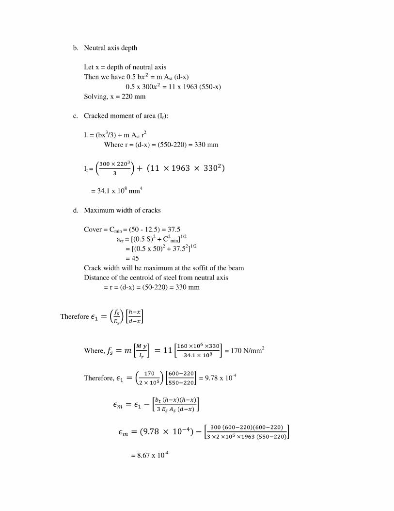
b. Neutral axis depth
Let x = depth of neutral axis
Then we have 0.5 b�/ = m Ast (d-x)
0.5 x 300�/ = 11 x 1963 (550-x)
Solving, x = 220 mm
c. Cracked moment of area (Ir):
Ir = (bx3/3) + m Ast r
2
Where r = (d-x) = (550-220) = 330 mm
Ir = T+**×//*K+ V +L11 × 1963 ×330/M
= 34.1 x 108 mm
4
d. Maximum width of cracks
Cover = Cmin = (50 - 12.5) = 37.5
acr = [(0.5 S)2 + C
2min]
1/2
= [(0.5 x 50)2 + 37.5
2]1/2
= 45
Crack width will be maximum at the soffit of the beam
Distance of the centroid of steel from neutral axis
= r = (d-x) = (50-220) = 330 mm
Therefore n2 = TO8i8V yzYH�YH{
Where, �� = w y|�XP { = 11 y2A*×2*a×++*
+..2×2*S { = 170 N/mm2
Therefore, n2 = T 26*/×2*fV yA**Y//*
00*Y//*{ = 9.78 x 10⁻⁴
n} = n2 − y'9LzYHMLzYHM+i878L�YHM {
n} = L9.78 × 10Y.M − y +**LA**Y//*MLA**Y//*M+×/×2*f×2,A+L00*Y//*M{
= 8.67 x 10⁻⁴
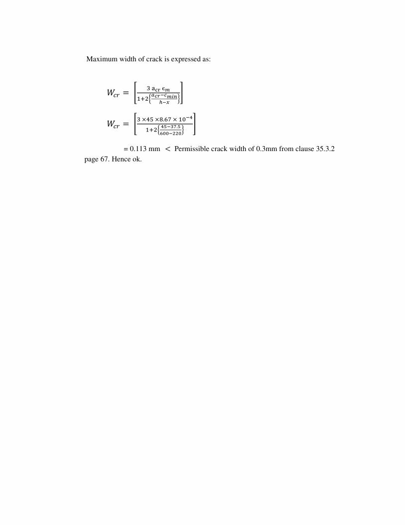
Maximum width of crack is expressed as:
~&: = W +���єZ2q/��FP�FZ����] �^
~&: = W+×.0×-.A6×2*�e2q/� ef�K�.facc�JJc� ^
= 0.113 mm< Permissible crack width of 0.3mm from clause 35.3.2
page 67. Hence ok.