Embed Size (px)
Citation preview

FINAL REPORT
1
AAIU Formal Report No: 2008-023
AAIU File No: 2007-0002
State File No: IRL00900867
Published: 15/09/2008
Operator: Aer Lingus
Manufacturer: Airbus
Model: A330-301
Nationality: Ireland
Registration: EI-DUB
Location: Approach to Runway (RWY) 22R,
Chicago O’Hare Airport (KORD), USA
Date/Time (UTC): 16 September 2006 @ 21.45 hrs UTC
NOTIFICATION
The Air Accident Investigation Unit (AAIU) was informed of this event on 9 January 2007,
almost four months after the incident. By that time, most records concerning the flight had
been discarded, other than the Operator’s Flight Data Monitoring (FDM) data. Although the
aircraft was not in any immediate danger during the occurrence, the AAIU had concerns due
to the reported late ATC clearance for a non-precision approach, the incident itself and the
amount of time this incident was within the Operator’s system without action or the AAIU
being notified.
The Chief Inspector of Air Accidents, in accordance with the provisions of SI 205 of 1997, on
09 January 2007, appointed Mr. Paddy Judge as the Investigator-in-Charge to carry out an
Investigation into this Incident and prepare a Formal Report.
SYNOPSIS
Three runways were in use for landing at Chicago O’Hare. The Commander, who was the
Pilot Flying (PF), briefed the Pilot-Not-Flying (PNF) for an Instrument Landing System (ILS)
approach to each landing runway. ATC vectored the aircraft towards an ILS approach to
RWY 22R but an unexpected and unusual clearance for a non-precision approach was
received shortly before commencing the approach. During the subsequent approach, in fine
weather with good visibility, the PF miscalculated the rate of descent required and descended
too rapidly. On realising that they were too low, power was increased and subsequently go-
around power was selected for a short period. The aircraft climbed to the proper profile and a
normal landing ensued. The maximum altitude deviation below the correct flight path was
774 ft. There was no injury or damage.

FINAL REPORT
2
INDEX
1. FACTUAL INFORMATION
1.1 History of the Flight
1.1.1 PF Interview
1.1.2 PNF Interview
1.1.3 Head of the Air Safety Office Interview
1.2 Injuries To Persons
1.3 Damage To Aircraft
1.4 Other Damage
1.5 Personnel Information 1.5.1 Commander
1.5.2 First Officer
1.6 Aircraft Information
1.7 Meteorological Information
1.8 Aids to Navigation
1.9 Communications 1.9.1 Air Traffic Control Clearance Phraseology
1.10 Aerodrome Information
1.11 Flight Recorders 1.11.1 Cockpit Voice Recorder
1.11.2 Flight Data Recorder
1.11.3 Flight Data Monitoring
1.12 Wreckage and Impact Information
1.13 Medical Information
1.14 Fire
1.15 Survival Aspects
1.16 Tests and Research
1.16.1 KORD/ORD ILS 22R Glide Path
1.17 Organizational and Management Information
1.17.1 General
1.17.1.1 Operations Manual Part A – SOPs for Approach and Go-around
1.17.1.2 Data Gathering Systems Agreement (DGSA)
1.17.1.3 Air Safety Office (ASO)
1.17.1.4 Operator Incident Classification
1.17.1.5 Operations Manual – Incident Reporting
1.18 Additional Information
1.18.1 International Civil Aviation Organisation (ICAO)
1.18.1.1 ICAO Annex 2 (Rules of the Air)
1.18.1.2 ICAO Annex 10, Vol. II (Aeronautical Communication Procedures)
1.18.1.3 ICAO Annex 11 (Air Traffic Services)
1.18.1.4 Filed Differences
1.18.2 Localiser Approach ATC Clearance
1.18.2.1 USA - Federal Aviation Administration (FAA)
1.18.2.1.1 Aeronautical Information Manual – FAA publication
1.18.2.1.2 Air Traffic Control handbook, FAA publication
1.18.2.2 ATC Localiser Approach Clearance – Ireland
1.18.2 3 ATC Localiser Approach Clearance – UK
1.18.2.4 ATC Localiser Approach Clearance – JAR
FINAL REPORT
3
1.18.3 Minimum Heights – General
1.18.3.1 Minimum Heights – Approach
1.18.4 Mandatory Occurrence Reporting (MOR)
1.18.5 PF Reporting of Occurrence
1.18.6 Flight Operations Management Interview
1.18.7 Operator’s Reporting and Recording system
1.18.8 Flight Data Monitoring System (FDM)
1.18.9 Instrument Approach Procedures – General
1.18.9.1 Non-Precision Approach Procedures
1.18.9.2 Flight Safety Foundation Data
1.18.9.3 Korean Air flight 801 on August 06, 1997
1.18.9.4 Delta Connection Flight 6448 on 18 February 2007
1.18.10 Non-Precision Approach Procedures - A330
1.18.10.1 Selected Approach
1.18.10.2 Managed Approach
1.18.10.3 Lateral Guidance
1.18.10.4 A330 Procedures
1.18.10.5 Navigation Database
1.18.11 In-Close Approach Change (ICAC)
1.19 Useful or Effective Investigation Techniques
2. ANALYSIS
2.1 Overview
2.2 The Incident 2.2.1 General
2.2.2 Standard Operating Procedures (SOPs)
2.3 ATC Factors
2.3.1 Overview
2.3.2 ATC Clearance Terminology and Phraseology
2.3.3 Regional Phraseology Variations
2.4 Non-Precision Approaches
2.4.1 General
2.4.2 Development
2.4.3 Technology Induced Constraints
2.4.4 Training Issues
2.4.5 Approach RWY 22R Vertical Profile
2.5 Approach Preparation
2.5.1 General
2.5.2 Vertical Profile Estimation
2.5.3 Human Factors
2.5.3.1 General
2.5.3.2 Clearance Clarification Difficulty
2.5.3.3 Approach
2.5.3.4 Go-Around
2.5.3.5 VFR Approaches
2.5.3.6 Visual Factors
2.5.4 Crew Resource Management (CRM)
2.5.5 Reporting of Incident
2.5.6 Confidential Report

FINAL REPORT
4
2.6 Operator’s Safety Management System
2.6.1 General
2.6.2 Occurrence Reporting
2.6.3 Air Safety Office
2.6.4 Air Safety Manual (ASM)
2.6.5 Flight Data Monitoring System
2.6.6 Data Gathering System Agreement
3. CONCLUSIONS
(a) Findings
(b) Cause
(c) Contributory Causes
4. SAFETY RECOMMENDATIONS
Appendix A
Chart 1 – KORD, Jeppesen 21-8, ILS RWY 22R
Chart 2 – KORD, Jeppesen 20-9, Chicago O’Hare ground chart
Chart 3 – KORD, FAA AL-166, ILS RWY 22R
Appendix B
Photo 1 KORD RWY 22R Approach at 6 nm
Photo 2 KORD RWY 22R Approach at 3 nm
Appendix C
KORD 22R Approach Slope Calculations
Appendix D
Haversine Calculations
Appendix E Glossary
FINAL REPORT
5
1. FACTUAL INFORMATION
1.1 History of the Flight
The flight operated from Dublin Airport (EIDW) to Chicago O’Hare (KORD) with the
Commander as PF and was conducted under Instrument Flight Rules (IFR). The flight
departed EIDW at 14.00 hrs UTC and was normal up to the commencement of the approach
to KORD. The aircraft was given radar vectors towards an expected ILS approach to RWY
22R, for which the crew had previously briefed. The pilot stated that the flight was then
cleared by ATC for an ILS 22R approach “Glide Slope (G/S) unusable” shortly before
position FNUCH (Appendix A, Chart 1). This required reprogramming the Flight
Management Guidance Computer (FMGC) and beginning a non-precision approach for
which the crew had not briefed. The approach was flown with the aircraft configured for
landing, gear down and flaps fully extended. The PF stated that he had initially set the correct
3º glide path angle but subsequently increased it, as he believed they were high. Shortly after
position RIDGE (4.5 nm from the threshold of RWY 22R), the PF realised that he was low.
Power was applied, and after initial uncertainty, the flight rapidly regained the correct profile
and a normal landing ensued at 21.56 hrs.
1.1.1 PF Interview
The PF stated he had briefed the PNF during the descent for a full ILS approach to each of the
three active runways, 22L, 22R and 27L, as identified on the ATIS (Automatic Terminal
Information Service). Subsequent to this, the flight was given radar vectors towards an
approach to RWY 22R.
About 3 to 4 nm before FNUCH, they were cleared for an “ILS 22R approach - Glide Slope
unusable”. This was the first indication the crew had that there was a problem with the ILS.
Although they were uncertain about this clearance, they decided the ATC controller meant a
“localiser only” (LOC) approach, as a G/S inoperative warning was showing on their
instruments, and proceeded on that basis. He commented that late runway changes happen
quite often at KORD.
This different approach clearance required reprogramming the FMGC through its keyboard
on the Multi-Control Display Unit (MCDU) and beginning an approach for which they had
not briefed. The PF requested the PNF to arm LOC and to set the Minimum Descent Altitude
(MDA) to 1,030 ft, or MDA + 50 ft1 in accordance with the Operator’s Standard Operating
Procedures (SOPs). The Progress page was selected on the MCDU and an entry made to
display the distance to go in nautical miles to the threshold of the runway as calculated by the
FMGC.
The approach, according to the PF’s recollection, was flown with autothrottle (AT) and
autopilot (AP) engaged, LOC mode engaged and with FPA (Flight Path Angle) mode2
selected. The approach was commenced with the aircraft configured gear down, full flaps
extended and was fully stabilised on the correct glide path at NOLEN, 13 miles out. The PF
initially set a normal 3º descent angle but increased this subsequently in his belief that they
were high. After position RIDGE, at about 200 ft above the MDA, the PF realised that he
was low. His recollection was that he saw the runway and the “landscape looked flat”.
1 An extra 50 ft is added to the MDA due to the inertia of the aircraft in descent.
2 This guidance mode allows the pilot to select a vertical flight path angle, as the FMGC compensates for
varying groundspeed.

FINAL REPORT
6
At this point he applied power, he believed Maximum Continuous Thrust (MCT), levelled off
and started a slight climb while assessing the situation. At this point also, some doubt came
into the situation with the PF believing he had called “Go-Around” but saying that, as the
PNF did not recall it, he could not be certain. He stated that if he had not called go-around he
had intended to do so.
The PF stated he then selected TOGA or go-around thrust and rotated the aircraft towards a
go-around pitch attitude. He thought he had also called for go-around flaps but could not be
sure. This would be normal in a go-around, but flaps were not repositioned. At this point the
aircraft was climbing and the PNF told the PF that he knew what was wrong and to just level
off. As they were coming into the normal visual landing slot and the aircraft was still
configured for landing, the PF made a decision to land. The aircraft regained the correct
profile and a normal landing ensued.
Following shutdown, there was a brief discussion of the incident where it emerged that the PF
had not taken the altitude of the airport into account when mentally calculating the rate of
descent required for landing. He believed this was due to insufficient time to brief for the
approach and an impression that he was high. That evening the PF recorded brief notes about
the flight, as was his normal procedure. The PF and PNF did not meet during the stopover,
which was not unusual. On the subsequent flight back, the following night, the PF believed
that they had a short discussion of the incident, which he stated the PNF did not remember.
Neither pilot was sure if the occurrence was a reportable incident as such. However, both felt
it should be reported due to the nature of the late change in approach procedure.
The PF had never previously encountered the ATC phraseology of “ILS 22R approach -
Glide Slope unusable” and admitted that doubt about the clearance may have affected his
performance.
The PF stated that he had not practised non-precision approaches (NPA) with intermediate
platform heights as the method trained by the Operator is to use a steady rate of descent from
the final approach fix (in this case NOLEN) to arrive at the MDA at or slightly before the
missed approach point. The PF appeared to the Investigation to view the 2,200 ft platform
restriction somewhat more desirable than mandatory.
In further communications, the PF confirmed that he had been initially trained in QFE3
procedures.
1.1.2 PNF Interview
The PNF recollection was that the weather was fine during the approach with good ground
contact but without being visual with the runway. He remembered a change of approach
procedure and the unusual ATC clearance for an “ILS 22R approach - Glide Slope unusable”
which he had not heard before. At the request of the PF, he reconfigured the FMGC for a
localiser only approach, crosschecked it and checked the go-around procedure, following
which he briefed the PF.
The approach seemed fine and a short distance before RIDGE he believed he selected the
Progress Page on the MCDU possibly on the request of the PF. When changed to the tower
frequency for landing he normally selects the Ground Control frequency on standby to
prepare for a frequency change immediately after landing.
3 An altimeter barometric setting that displays height above the runway.

FINAL REPORT
7
This would have required him to review the KORD Airport layout – Jeppesen Chart 20-9
(Appendix A, Chart 2) and so he believed he was out of the loop and not monitoring the
flight path for some time. He was not anticipating any problem. He remembered looking up
and thinking this does not look right. The PF said, “Something is wrong here”. He saw the
runway and the preceding aircraft ahead and knew the picture did not look right. He checked
the RADALT (Radio Altimeter) versus the distance to go on the Progress Page and knew
what was wrong. He believed he said to the PF “…I know what’s wrong I’ll talk to you on
the ground - if you level off”. He stated that by then, “we were about 4 miles from the
threshold and 400-500 ft low, but not dangerously so, the aircraft was fully configured and
we were well above the minimum descent altitude (MDA)”. The PF applied power. He did
not expect him to select TOGA as he assumed the PF would use about 75% power to regain
the landing slot. Having climbed slightly the aircraft continued the approach and landed
normally. He did not remember the PF calling go-around or for go-around flaps and did not
select flaps to the go-around position.
There was a short discussion of the incident after landing. At the termination of the flight, the
PNF stated he was under the impression that the PF was going to submit a Captain’s Special
Report (CSR) and assumed he did.
Later he had checked the time required to physically change the approach on the MCDU. He
could not do this in less than 10 seconds. In addition, 12 seconds was required for checking
ATC ground frequency and selecting it on the radios.
He believed there was a good professional relationship between himself and the PF and was
upset that he had not monitored the situation adequately as he had not expected anything
abnormal to happen.
1.1.3 Head of the Air Safety Office (ASO) Interview
The Head of Air Safety (HAS), when interviewed four months after the occurrence, recalled
that three to four weeks after the event the PF visited him. The PF discussed submitting
either a confidential report or a CSR through normal executive channels.
Two to three weeks afterwards a written report was submitted by the PF. This confidential
report inaccurately stated that the aircraft arrived at 100 ft above minima at 3 nm before the
runway. This confidential report, de-identified and undated, was immediately typed up and
sent by the HAS to Flight Operations Management (Flt Ops). The HAS kept no records and
had no further contact, at that time, with the PF in accordance with the confidential system
guidance as given in the Air Safety Manual.
However, the HAS was subsequently involved in investigating the occurrence and
interviewing the crew who, he stated, cooperated fully.
The HAS felt he was somewhat limited in his ability to assess the occurrence, when it was
initially reported, as his background was technical without any flying experience.
None of the staff members in the ASO had flying experience and only the HAS had
investigation training. He therefore, on the verbal information supplied to him by the PF, the
lack of any data from the flight and his own lack of operational expertise, was in a limited
position to assess whether this was a reportable occurrence or not and to advise what
reporting channel should consequently be used.

FINAL REPORT
8
1.2 Injuries To Persons No injuries were reported to the investigation
Injuries Crew Passengers Total in aircraft Others
Fatal: 0 0 0 0
Serious: 0 0 0 0
Minor: 0 0 0 Not applicable
None: 12 307 319 Not applicable
TOTAL: 12 307 319 0
1.3 Damage To Aircraft
None.
1.4 Other Damage
None.
1.5 Personnel Information
1.5.1 (Commander)
Personal Details: Male, aged 48 years
Licence: ATPL
Last Periodic Check 13 Sept 2006
Medical Certificate 01 Sept 2006
Flying Experience:
Total all types: 11,938 hours
Total all types PI 8,648 hours
Total on type: 2,986 hours
Total on type PI 2,900 hours
Last 90 days: 126 hours
Last 28 days: 75 hours
Last 24 hours: 0 hours
Duty Time:
Duty Time up to incident: 9 hours
Rest period prior to duty: 40 hours 10 mins
1.5.2 (First Officer)
Personal Details: Male, aged 42 years
Licence ATPL
Last Periodic Check: 27 April 2006
Medical Certificate: 25 August 2006
Flying Experience:
Total all types: 6,861 hours
Total all types PI: 0 hours
Total on type: 1,618 hours
Total on type PI: 0 hours

FINAL REPORT
9
Last 90 days: 144 hours
Last 28 days: 43 hours
Last 24 hours: 0 hours
Duty Time:
Duty Time up to incident: 9 hours
Rest period prior to duty: 96 hours
Both pilots’ licences were valid with current medicals, instrument ratings and competency
certificates issued by the Irish Aviation Authority (IAA).
1.6 Aircraft Information
There were no significant defects in the Technical Log. Neither powerplant nor the
maintenance condition of the aircraft, which was properly certified, was a factor in this
incident.
1.7 Meteorological Information
Meteorological Actual Reports (METARs) for KORD for the day were obtained. These
indicated that, at the time of the event, it was a clear day with some cloud at high levels. The
METAR recorded at 21.51 hrs UTC, shortly after the occurrence, shows a wind velocity of
160º/13 kts, 10 miles visibility4, few clouds at 12,000 ft, broken cloud at 25,000 ft,
temperature 25 C, and dew point 14 C with a sea level pressure of 29.92 inches5. The
weather reports for one hour before and after the event are similar, indicating a fine autumnal
day with good visibility and a slight crosswind from the left for approach and landing.
Conditions were similar to those photographs later recorded on approach to KORD ILS 22R
(Appendix B).
1.8 Aids to Navigation
The ILS on KORD RWY 22R transmits on 111.3 MHz with an inbound bearing of 220º.
Chicago ATC's records indicate that the RWY 22R glide slope was out of service from
21.20 hrs to 21.57 hrs. The occurrence happened during this period.
1.9 Communications
1.9.1 Air Traffic Control Clearance Phraseology
The flight crew both stated that they felt uncertainty about the ATC approach clearance
phraseology of an “ILS 22R approach - Glide Slope unusable”, which they did not clarify.
They stated that they believed the approach clearance should have been for a “localiser only
approach” for which they would have been cleared in their native JAR6 environment from
whence the aircraft departed.
The Investigation is aware that the clearance for an “ILS approach - Glide Slope unusable” is
given in other regions of the world in circumstances where the ATC glide slope monitoring
status indicator is unserviceable but the ILS is transmitting.
4 Visibility in excess of 10 miles is not recorded.
5 A sea level pressure or QNH of 29.92 inches converts to 1013.2 hectopascals or standard atmospheric pressure.
6 Joint Aviation Requirements are used by 42 European countries.
FINAL REPORT
10
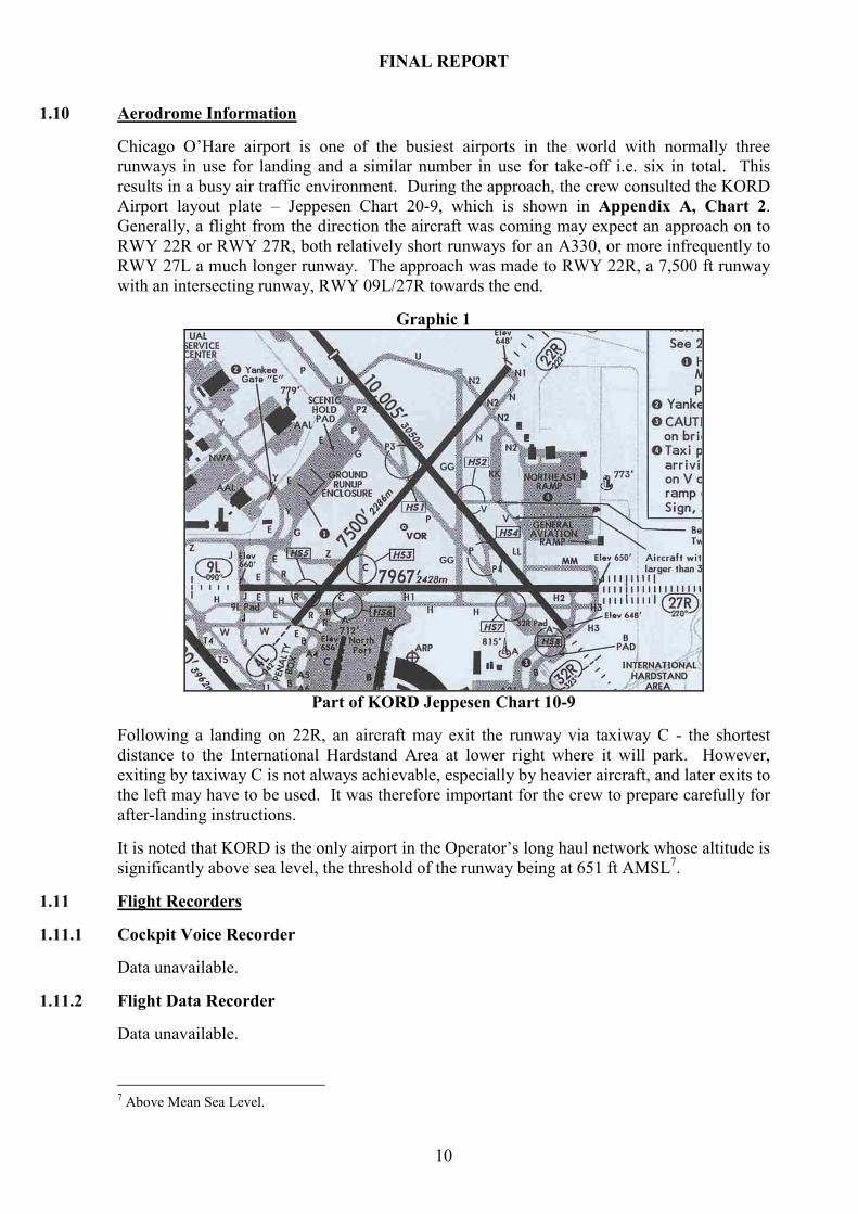
1.10 Aerodrome Information
Chicago O’Hare airport is one of the busiest airports in the world with normally three
runways in use for landing and a similar number in use for take-off i.e. six in total. This
results in a busy air traffic environment. During the approach, the crew consulted the KORD
Airport layout plate – Jeppesen Chart 20-9, which is shown in Appendix A, Chart 2.
Generally, a flight from the direction the aircraft was coming may expect an approach on to
RWY 22R or RWY 27R, both relatively short runways for an A330, or more infrequently to
RWY 27L a much longer runway. The approach was made to RWY 22R, a 7,500 ft runway
with an intersecting runway, RWY 09L/27R towards the end.
Graphic 1
Part of KORD Jeppesen Chart 10-9
Following a landing on 22R, an aircraft may exit the runway via taxiway C - the shortest
distance to the International Hardstand Area at lower right where it will park. However,
exiting by taxiway C is not always achievable, especially by heavier aircraft, and later exits to
the left may have to be used. It was therefore important for the crew to prepare carefully for
after-landing instructions.
It is noted that KORD is the only airport in the Operator’s long haul network whose altitude is
significantly above sea level, the threshold of the runway being at 651 ft AMSL7.
1.11 Flight Recorders
1.11.1 Cockpit Voice Recorder
Data unavailable.
1.11.2 Flight Data Recorder
Data unavailable.
7 Above Mean Sea Level.

FINAL REPORT
11
1.11.3 Flight Data Monitoring (FDM)
The following data in Table 1 is derived from both the Operator’s FDM system for the
incident flight and the published approach plate, Jeppesen Chart 21.8 of 10 MAR 06
(Appendix 1, Chart 1), as used by the flight crew. Graphic 2 overleaf depicts Table 1 in
graph format.
Table 1
Waypoint ORD DME
Dist to RWY
Aircraft Altitude
Platform Altitude
Deviation from Platform
Aircraft Height
Ideal Height
Deviation from ideal
FNUCH 19.5 18.8 6,000 7,000 -1,000 5,349 6,086 -737
NOLEN 13.7 13 5,000 5,000 0 4,349 4,208 +141
8.7 8 2,880 2,200 680 2,229 2,590 -361
7.7 7 2,500 2,200 300 1,849 2,266 -417
6.7 6 2,080 2,200 -120 1,429 1,942 -513
5.7 5 1,620 2,200 -580 969 1,619 -650
RIDGE 5.2 4.5 1,426 2,200 -774 775 1,457 -682
4.7 4 1,160 1,220 -60 509 1,295 -786
3.7 3 1,420 1,220 200 769 971 -202
2.7 2 1,400 1,220 180 749 647 +102
D.2.2 2.4 1.7 1,280 1,220 60 629 550 +79
1.7 1 1,000 980 20 349 324 +25
RWY 0.7 0 0
Approach Data – RWY 22R KORD
NOTES on Table 1:
1) Data taken from the FDM is identified by bold type, approach platform restrictions by
yellow and deviation by red.
2) Height refers to the distance the aircraft is above the ground (specifically the runway
Touchdown Zone) whereas altitude, which the pilot flew, refers to the distance of the
aircraft above sea level.
3) The ORD DME was not recorded by the FDM, fix information was. ORD DME
distances are derived from a 0.7 nm correction added to the recorded Distance to
Runway. This is calculated from the D2.2 fix on the chart (2.2 – (0.4+1.1) = 0.7 nm).
4) Dist to RWY and Aircraft Altitude were obtained from the aircraft’s FDM recordings.
5) Platform Altitude is taken from the published approach and is explained in Section
1.16.1.
6) Deviation from Platform is the result of Aircraft Altitude less Platform Altitude.
7) Aircraft Height is height above the touchdown zone (651 ft AMSL) of the runway at
that time, calculated at Aircraft Altitude less 651 ft.
8) Ideal heights have been calculated from the published groundspeed on the chart of 140
knots at a rate of descent of 753 ft/min. This equates to a rate of descent of 322.7 ft per
NM. The descent rates published on the chart vary from 319 ft to 323 ft per NM for
groundspeeds from 100 kts to 160 kts.
9) Deviation from ideal results from Aircraft Height less Ideal Height.

FINAL REPORT
12
Graphic 2
NOTE: Scale distance in the above graphic is non-linear.
The data showed the flight crossing waypoint FNUCH at 6,000 ft or 1,000 ft lower than the
published approach height. This is a common ATC procedure. Passing NOLEN the aircraft
was correctly positioned on the vertical profile. At 6 nm from the runway, it had descended
120 ft below platform. It continued the descent and reached its maximum deviation (774 ft)
at RIDGE, 4.5 nm from the runway threshold.
At 4 nm, the flight was at the lowest point during the incident, 1,160 ft or 509 ft above the
ground. However, platform deviation had reduced to 60 ft - as the platform height reduced
from 2,200 ft to 1,220 ft at RIDGE. From this point, the aircraft climbed and subsequently
tracked the correct profile.
The FDM data showed that the approach was conducted with both autopilot (AP) and
autothrust (AT) engaged, gear down and full flaps extended. At 4 nm, the PF initially applied
Maximum Continuous Thrust (MCT) for 5 seconds followed by Take-Off/Go-Around
(TOGA) thrust. The PF disconnected the autopilot and increased the nose-up pitch attitude
from +1º to +7.5º. TOGA was engaged for 4 seconds after which power was reduced. The
aircraft configuration of gear down and full flap deployed was not changed.
1.12 Wreckage and Impact Information
Not Applicable.
1.13 Medical Information
Not Applicable.

FINAL REPORT
13
1.14 Fire
Not Applicable.
1.15 Survival Aspects
Not Applicable.
1.16 Tests and Research
1.16.1 KORD/ORD ILS 22R Glide Path
This Graphic depicts the glide slope/glidepath8 of the published ILS RWY 22R at KORD and
is an extract from Jeppesen Chart 21.8 of 10 MAR 06, Appendix A, Chart 1.
Graphic 3
Glide Path ILS 22R KORD –
NOTE:
• The glide slope (GS) is shown as a 3.00º angle (see blue arrow).
• NPA platform altitudes, the minimum altitudes during that sector of the approach,
are shown as a dashed line.
• The NPA platform altitude shows above the glide slope at RIDGE and D2.2
• The terminology used on the chart for an approach with a glide slope inoperative is
“LOC (GS out)”
Due to the unusual depiction of platform heights above the glidepath at RIDGE and D2.2, the
Investigation examined this further. Calculations of the descent angles from each platform
height fix point to touchdown are detailed in Table 2 below.
8 In this document, the term glide slope refers specifically to the vertical element of the ILS beam whereas
glidepath refers to the descent profile determined for vertical guidance during any final approach.

FINAL REPORT
14
Table 2
Platform
Altitude
Platform
Height
Stage
Distance
Total
Dist
Total
Dist ft Slope
Descent
angle
FNUCH 7000 6349 5.80 18.90 114,912 0.055 3.16
NOLEN 5000 4349 8.60 13.26 80,648 0.054 3.09
RIDGE 2200 1549 3.00 4.66 28,360 0.055 3.13
D2.2 1220 569 1.50 1.66 10,120 0.056 3.22
Touchdown 651 0 0.16 0.16 1,000 0.000 0.00
KORD RWY 22R Glidepath angles
NOTE: A touchdown distance of 0.16 nm (1,000 ft) has been added, as landing aircraft
should touchdown 1,000 ft down the runway.
Calculations show that the glidepath and glide slope angle at FNUCH is close to 3.2º and at
NOLEN 3.1º. The glidepath at the Final Approach Fix RIDGE is 3.1º and at D2.2, 3.2º. This
reflects the Jeppesen approach chart depiction of platform heights above the published
3º glide slope.
In view of the differences between the published glide slope and the angles calculated the
Investigation requested a copy of the USA FAA approach chart in force on the date of the
event. The heights, distances and glide slope angle on the FAA 22R AIP chart (Appendix A,
Chart 3) were identical to those on the Jeppesen chart. As a result, latitude and longitude
coordinates for each platform point and the runway threshold were requested through the
National Transportation Safety Board (NTSB) of the USA. From these, inter-fix distances
were calculated using the Haversine9 formula. The calculations confirmed the accuracy of the
distances published on the AIP chart. Minor differences in distance (a maximum of 266 ft at
NOLEN) due to rounding up were noted, but the accuracy of the inter-stage distances
published on the charts was confirmed. These minor differences did not affect the
calculations in the Slope or G/P angle columns above.
Approach designs in the United States are published under Terminal Design Procedures
(TERPS). In TERPS, the larger air transport Group 4 aircraft is assumed to be over the
runway threshold at 55 ft when landing. The approach 3º glide slope was consequently
assumed to pass through that point and the resulting altitudes at the Fixes were calculated as
per Appendix C. This also showed a similar picture to the above regarding the glidepath.
1.17 Organizational and Management Information
1.17.1 General
Standard Operating Procedures (SOPs) are guidelines or directives designed to protect the
aircraft, its crew and passengers by giving a standard set of actions to deal with situations.
Within the context of this Investigation, of initial interest are the Operator and Manufacturer
published SOPs for operation of the aircraft, which the crew should have followed during the
approach. Of further interest is the incident classification system published by the Operator
and the method used to report and record the incident. Of relevance also are the FDM system
that revealed the occurrence, the procedures associated with FDM and the function of and
procedures within the Air Safety Office.
9 The Haversine formula is an equation used in spherical trigonometry that gives great-circle distances between
two points on the surface of a sphere by using their longitudes and latitudes.

FINAL REPORT
15
1.17.1.1 Operations Manual Part A – SOPs for Approach and Go-around
The Operator has published general crew guidance and SOPs for approach in its Operations
Manual (Part A Date: 01/01/04, Issue 2).
8.1.2 GENERAL GUIDANCE
One of the main reasons for collision with terrain would appear to be complacency, or
lack of a sense of immediate danger, in the cockpit. It is suggested that the best remedy
lies in the realm of cockpit procedures, particularly during initial approach. It is
imperative, during descent and approach, that Commander and co-pilot independently
monitor the navigation of the aircraft and thus eliminate gross navigational errors.
Navigation, of course, is three-dimensional and height should be monitored as well as
geographical position. It is important, therefore, that the PM (Pilot Monitoring i.e.
PNF) particularly does not allow supplementary activities to distract him from
monitoring of the aircraft’s position or of its altitude.
8.4.8.1 STANDARD APPROACH PROCEDURES - GENERAL
It is company policy that every approach is stabilised early enough for pilots to be able
to detect wind shear or other unacceptable deviations from the correct flight profile.
1,000 ft Gate: On all approaches at 1,000 ft above terrain, as measured by the radio
altimeter, the aircraft should be stabilized in the planned landing or final approach
configuration, and the glide slope or correct vertical profile established. If these
criteria are not met, then serious consideration should be given to initiating an
immediate go-around or missed approach.
8.7 APPROACH ANGLE NON PRECISION APPROACH
In all cases of final approach where no glidepath reference is available (e.g. no ILS,
VASI, etc.), the flying pilot shall aim for a 3° glidepath.
The Operators Operations Manual Part B1-33 specifies the Operating Procedures for a
Selected Non-Precision Approach on the Airbus A330.
DESCENT PROFILE
Pilots should arrange descent profile to fly continuous descent approaches where
possible, subject to remaining at or above minimum descent altitudes.
The SOPs for approach include:
PM calls out recommended/hard altitudes for each nautical mile of the approach
(Where these are not promulgated on the approach plate, insert the runway threshold in
the MCDU PROG page and calculate estimated altitudes for each NM).
GO-AROUND
Part of the SOPs for go-around states “Once the decision has been taken to Go-around during
final approach no decision to abandon this shall be taken.”
Once the go-around has been initiated, the aircraft FCOM (Flight Crew Operating Manual
Volume) 3.2.3 SOP initial actions for go-around are:
FINAL REPORT
16
Apply the following three actions simultaneously:
THRUST LEVERS TOGA
ANNOUNCE "GO AROUND – FLAPS”
ROTATION PERFORM
1.17.1.2 Data Gathering Systems Agreement (DGSA)
Over 20 years ago, the operator and its pilots implemented an Operational Monitoring System
whose principles were incorporated in an agreement, the DGSA. It states that the system
aims to enhance flight safety by monitoring data on an active basis to detect undesirable
practice and negative trends and correct them before they can ever be manifested as
accidents or incidents. The agreement also guarantees the internal confidentiality of the
system’s workings and data.
ICAO Annex 6 Part I Paragraph 3.2.3 requires the operators of aeroplanes of a certificated
take-off mass in excess of 27,000 kg to establish and maintain a Flight Data Monitoring
Program as part of its Accident Prevention and Flight Safety Program, effective from 1
January 2005. Paragraph 3.6.4 states that the flight data analysis programme shall be non-
punitive and shall contain adequate safeguards to protect the source(s) of the data. ICAO
Safety Management Manual (SMM) Doc 9859 AN/460 in paragraph 16.3.5 states, regarding
a Flight Data Analysis (FDA) programme, that; the details are normally contained in a
formal agreement between management and flight crew. As a consequence of this the parties
then reviewed the DGSA to ensure it was ICAO Annex 6 compliant and the system was
thereafter referred to as the FDM program.
Although the system is designed as non-punitive and should not be used to monitor or check a
pilot’s judgement, it can be used in defined circumstances, such as to remedy individual bad
practice or training issues, or in association with an incident investigation, hence the
sensitivities associated with FDM use. Usually though, it is more concerned with general
trends in the operation or, as in this case, particular types of approaches at specific airports.
It is noted that paragraph A8 of the DGSA states that the FDM data will be provided on
request to the Investigator-In-Charge (IIC) in the event of an accident/incident category A &
B as defined in the Aer Lingus Safety Manual. However, under S.I. 205 of 1997 paragraph 9,
the AAIU may take possession of whatever data it deems relevant to investigating an
occurrence and the voluntary provisions of the DGSA no longer apply.
1.17.1.3 Air Safety Office (ASO)
Guidance on Safety Management Systems is provided in the ICAO Safety Management
Manual (SMM) Doc 9859 AN/460. Chapter 12 outlines operator guidance for a Safety
Office, part of which includes the requirement for selection of staff with adequate skill sets
and relevant experience and to provide subsequent safety training. The Air Safety Office has
three staff, all from a technical or administrative background.
The Operator’s Air Safety Systems and procedures are published internally in its Air Safety
Manual (ASM), Revision 1 March 2004:
The primary objective of the Air Safety organisation is the discovery and elimination, or
avoidance of risk. The Air Safety Office provides an independent safety oversight of
operations.

FINAL REPORT
17
A secondary function is to investigate any accident or incident involving one of its
aircraft.
The ASO is an advisory, not an executive, function. As such, it did not, at the time of the
incident, report through the management structure but independently to the Accountable
Manager10
, in this case the Chief Executive.
The ASO operates two incident reporting systems, one a non-punitive system and the other a
confidential system. The ASM gives examples of incidents that may be reported through the
non-punitive incident reporting system. However, no examples or guidance is given
regarding incidents that may be reported by means of a confidential report.
Paragraph 2.1.1 of the Air Safety Manual (ASM) states:
It is the responsibility of the Head of Air Safety to (inter-alia):
9. Operate a Confidential Reporting System. The Head of Air Safety has absolute
discretion in the handling of all information provided under this confidential system,
detailed in Part 2, Para 2.5 of this manual.
Part 2, paragraph 2.5, outlines the confidential reporting system procedures. Here the HAS is
authorised to accept a confidential report from any staff member, who may report in person,
by phone or anonymously. If the reporter supplies a name it must be deleted after 48 hours,
after which time the HAS does not contact the reporter. The HAS has absolute discretion in
handling the information supplied and the ASM states he may decide that “anonymised
details of confidential reports may be published in the interests of enhancing Air Safety”.
It is noted that neither the management chart in 1.3 nor management functions chart in 2.1.5
reflected the management structure at the time.
1.17.1.4 Operator Incident Classification
Part 3 of the Air Safety Manual covers Incident categories or classification and reporting
procedures. Paragraph 3.2.1 defines Safety events under the following categories:
Category A: Major Accident
Category B: Serious Incident
Category C: Incident
The ASM continues by defining these categories and gives procedures to be used when an
accident or incident is reported. Of relevance in this occurrence is Category C, or
occurrences that significantly reduce the Air Safety margins of the operation. Among the
many examples listed, the following are relevant to this incident:
5. Unstabilised Approach,
9. Altitude Deviation in excess of 300 feet, and ……
42. Any event, which may provide useful information for the enhancement of Air Safety
10 The nominated manager who had corporate responsibility for ensuring that all operations and maintenance
activities can be financed and carried out to the required standard under JARs.

FINAL REPORT
18
1.17.1.5 Operations Manual – Incident Reporting
The Operator, in Part A, 11.2 of its Operations Manual, publishes crew procedures for
accidents and incidents.
In 11.2.1, an incident is defined as:
For Flight Operations’ purposes an incident is defined as any occurrence, other than an
accident, associated with the operation of an aircraft which: (Seven examples are then given
of incidents of which the most relevant is)
(b) Under slightly varied circumstances, may have jeopardised the safety of the
passengers, crew or aircraft, or may have resulted in an aircraft accident and/or
incident.
Section 11.2.2 of the manual continues by outlining the procedures for informing base. It
further states that if a Commander is in any doubt an incident signal should be raised.
Section 11.2.3 lists the subsequent executive action to be taken.
Section 11.3 introduces Mandatory Incident Reports and gives many examples of a list of
incidents that must be reported, which include:
11.3.2.13 When a Height Control error of more than 300 feet occurs.
and
11.3.2.33 When Any Event, which may provide useful information for the enhancement
of air safety, occurs.
It also states that the list is not exhaustive.
The ASM states that the line manager must report incidents directly to Operations Control.
The Duty Operations Controller will promulgate an Incident Signal, such Incident Signals
being copied to the relevant Irish Authorities, namely the IAA and the AAIU. The HAS also
has the authority to raise an Incident Signal. It also states that Incident Signals concerning
events in Category A and B must be discussed, before transmission, with the Chief Executive.
1.18 Additional Information
1.18.1 International Civil Aviation Organisation (ICAO)
ICAO publishes internationally agreed procedures for civil aviation. These agreed
procedures are translated into local law by individual States. ICAO was founded as a result
of the Chicago Convention of 1944. The Convention recognises that every State has
exclusive sovereignty over the airspace above its country. The ICAO procedures are
published in the form of Annexes to the Convention on International Civil Aviation of which
there are 18. Standards and Recommended Practices (SARPS) are published in each Annex;
a Standard is compulsory, a Recommended Practice is desirable.
Relevant to the ATC dimension of this incident are:
Annex 2 (Rules of the Air).
Annex 10 (Aeronautical Communications), Volume II covers Procedures.
Annex 11 (Air Traffic Services) of which ATC is a subset.

FINAL REPORT
19
The SARPS in Annexes 2 and 6 cover rules and operation of the flight while those in
Annexes 10 and 11 and the PANS ATM (Procedures for Air Navigation Services – Air
Traffic Management) govern the application of the Procedures.
1.18.1.1 ICAO Annex 2 (Rules of the Air)
Section 3.6 in Note 2 states: If an air traffic control clearance is not satisfactory to a pilot-
in-command of an aircraft, the pilot-in-command may request and, if practicable, will be
issued an amended clearance.
1.18.1.2 ICAO Annex 10, Vol. II (Aeronautical Communication Procedures)
Annex 10, Aeronautical communications, contains five volumes of which Volume II covers
Communication Procedures including those with PANS status.
PANS or Procedures for Air Navigation Services are approved by ICAO for worldwide
application. They contain, for the most part, operating procedures regarded as not yet having
attained a sufficient degree of maturity for adoption as International Standards and
Recommended Practices, as well as material of a more permanent character which is
considered too detailed for incorporation in an Annex, or is susceptible to frequent
amendment, for which the processes of the Convention would be too cumbersome.
Part 5.1 General states inter alia:
5.1.1.1 ICAO standardized phraseology shall be used in all situations for which it has been
specified. Only when standardized phraseology cannot serve an intended transmission, plain
language shall be used.
Note - Detailed language proficiency requirements appear in the Appendix to Annex 1.
5.1.1.3 Recommendation. — In all communications, the consequences of human performance
which could affect the accurate reception and comprehension of messages should be taken
into consideration.
Note - Guidance material on human performance can be found in the Human Factors
Training Manual (Doc 9683).
5.2.1.9.1 Communications shall be concise and unambiguous, using standard phraseology
whenever available.
In addition:
• Section 5.2 covers Radiotelephony procedures and,
• Subsection 5.2.1.5.8 gives standard words and phrases that shall be used in
radiotelephony communications.
Standard phraseologies for these procedures are further outlined in ICAO Air Traffic
Management Doc 4444, ATM/501 where Section 12.3 deals with ATC phraseologies and
Section 12.3.3 covers Approach control services. The phraseology published here is for
general type approaches but that phraseology is amplified in the Manual of Radiotelephony
Doc 9432 AN/925, Third Edition 2006 where it states” ICAO phraseologies are developed to
give efficient, clear, concise and unambiguous communications”. However, it further states,
“it is not possible to provide phraseologies to cover every conceivable situation which may
arise and the examples contained in the manual are not exhaustive, but merely representative
of radio telephony phraseology in common use”.

FINAL REPORT
20
Instrument approach phraseology is covered in Chapter 7.3 Approach Control – IFR Arrivals,
and clearance examples are given for ILS (7.3.1) and NDB (7.3.2) approaches. Although
phraseology examples of various types of radar approaches are given, there are no examples
of approaches for either a localiser or a VOR approach.
1.18.1.3 ICAO Annex 11 (Air Traffic Services)
This Annex pertains “to the establishment of airspace, units and services necessary to
promote a safe, orderly and expeditious flow of air traffic. A clear distinction is made
between air traffic control service, flight information service and alerting service. Its
purpose, together with Annex 2 is to ensure that flying on international air routes is carried
out under uniform conditions designed to improve the safety and efficiency of air operation”.
1.18.1.4 Filed Differences
Where differences exist between the national legislation of contracting states and an ICAO
Annex the state is required to notify ICAO of those differences.
The Supplement to Annex 10 shows that both Ireland and United States have notified ICAO
that no differences exist in regard to this Annex.
The Supplement to Annex 11 shows that Ireland has notified ICAO that no differences exist
whereas no information has been received from the United States.
1.18.2 Localiser Approach ATC Clearance
The Investigation therefore contacted the Federal Aviation Administration (FAA) of the
United States and both local and international Authorities of Europe to clarify ATC clearance
phraseology for a localiser approach.
1.18.2.1 USA - Federal Aviation Administration (FAA)
The FAA clarified the clearance as follows. The relevant FAA/ATC procedures for an NPA
with a glide slope unusable are given in two manuals; guidance for pilots is provided in the
Aeronautical Information Manual (AIM), and for ATC controllers in the Air Traffic Control
Handbook.
1.18.2.1.1 Aeronautical Information Manual – FAA publication
The Aeronautical Information Manual (AIM) advises:
AIM 1-1-9. Instrument Landing System (ILS):(j) Inoperative ILS Components (2) Inoperative
glide slope. When the glide slope fails, the ILS reverts to a non -precision localizer approach.
In communication with the Investigation, the FAA stated that this paragraph does not
constitute any basis for the phraseology that is used by the controller in such cases, it simply
makes the pilot aware of the limitations on the navigation signal in this configuration.
1.18.2.1.2 Air Traffic Control handbook, 7110.65 – FAA publication
The FAA has indicated that the Air Traffic Control handbook, FAA Document 7110.65
establishes the criteria and phraseology to be used by the controller.

FINAL REPORT
21
Section 8, Approach Clearance Procedures, states inter alia:
4-8-1. APPROACH
a. Clear aircraft for "standard" or "special" instrument approach procedures only. To
require an aircraft to execute a particular instrument approach procedure, specify in the
approach clearance the name of the approach as published on the approach chart. Where
more than one procedure is published on a single chart and a specific procedure is to be
flown, amend the approach clearance to specify execution of the specific approach to be
flown. If only one instrument approach of a particular type is published, the approach needs
not be identified by the runway reference. An aircraft conducting an ILS/MLS approach
when the glide slope/glidepath is reported out of service shall be advised at the time an
approach clearance is issued. Standard Instrument Approach Procedures shall commence at
an Initial Approach Fix or an Intermediate Approach Fix if there is not an Initial Approach
Fix.
PHRASEOLOGY-
(To authorize a pilot to execute an ILS/MLS approach when the glide slope/glidepath is out of
service),
CLEARED (type) APPROACH, GLIDE SLOPE/GLIDEPATH UNUSABLE.
EXAMPLE-
………….
"Cleared I-L-S Runway Three Six Approach, glide slope unusable."
NOTE:
The name of the approach, as published, is used to identify the approach, even though a
component of the approach aid, other than the localizer on an ILS or the azimuth on an MLS
is inoperative.
1.18.2.2 ATC Localiser Approach Clearance - Ireland
The Investigation has not been able to identify any documentation defining the ATC
phraseology that should be used for a localiser non-precision instrument approach. Following
queries to the Irish Aviation Authority (IAA) the Investigation has been informed that the
standard ATC clearance for such an approach is “Cleared localiser only approach, RWY XX”.
1.18.2.3 ATC Localiser Approach Clearance - UK
The United Kingdom ATC Radiotelephony Manual is titled CAP 413, Edition 16. Examples
of radar, VDF, NDB and VOR approaches are given in this manual. Localiser Only
approaches are not covered. The UK CAA has informed the Investigation that the normal
ATC clearance in UK airspace for an approach with an inoperative glide slope is “Cleared for
Localiser Approach Runway XX”.
1.18.2.4 ATC Localiser Approach Clearance - JAR
The Joint Aviation Authority (JAA) Administrative & Guidance Material Section One:
General Part 3: Temporary Guidance Leaflets in Section 1, Part 3, 6-38 states;

FINAL REPORT
22
7.1 The following items should also be included in flight crew training programmes:
(a) knowledge and understanding of standard ATC phraseology used in each area of
operations.
JAR-OPS, Section 4/Part 2 Procedures (App. 2-6 01.0606.988) defines what is meant by area
of operation and the factors that limit its extent:
1. Areas of Operation
1.1 The Authority, when considering the issue of an AOC, should stipulate a geographical
limit within which the operation is to be confined. In some circumstances it will be
appropriate to permit commercial operations ‘world-wide’ or ‘with no geographical
limit’.
1.2 The following factors should be taken into account when deciding the Area of
Operation within which Commercial Air Transportation will be permitted…
d) The need for the Flight Crew to comply with non-standard ATC requirements such
as:
- the use of non-standard phraseology;
- the use of altitude clearances in metres;
- the use of altimeter settings
JAR FCL 1 and 2 also cover ATC phraseology but this is in association with initial pilot
training in standard communication procedures and phraseology. The Investigation has been
unable to discover any other relevant ATC phraseology references in JAA publications.
1.18.3 Minimum Heights - General
As the aircraft was flying in the United States at the time of the event, the Rules of the Air
appropriate to that region were in force. FAR Part 91 (Applicable to all aircraft) Section
91.119 states, inter alia:
Except when necessary for take-off or landing, no person may operate an aircraft below the
following altitudes:
(b) Over congested areas. Over any congested area of a city, town, or settlement, or over
any open air assembly of persons, an altitude of 1,000 ft above the highest obstacle
within a horizontal radius of 2,000 ft of the aircraft.
(c) Over other than congested areas. An altitude of 500 ft above the surface, except over
open water or sparsely populated areas. In those cases, the aircraft may not be operated
closer than 500 ft to any person, vessel, vehicle, or structure.
However, as the aircraft nears the runway it needs to descend and the minimum heights for
this phase of flight are published using approach design criteria.
1.18.3.1 Minimum Heights - Approach
Approach design guidance criteria are published in ICAO PANS-OPS DOC 8168 and TERPS
procedures in the United States, which are similar to PANS-OPS. In the approach design, a
platform height is the minimum obstacle clearance height for a specific sector of an approach.
Platform heights are published to ensure the aircraft is at a safe height above the ground at all
times during instrument approaches. The obstacle clearance heights are derived from a
complex three-dimensional surface projection based on the PANS-OPS criteria above.
FINAL REPORT
23
1.18.4 Mandatory Occurrence Reporting
As a result of Directive 2003/42/EC of the European Commission, the Irish Aviation
Authority issued Aeronautical Notice (AN) No. G10 Issue 1 of 31/08/2005.
This covers mandatory reporting of relevant occurrences and contains a comprehensive list of
aircraft operations, maintenance, repair and manufacturer-related occurrences that must be
reported.
It is noted that since this incident Statutory Instruments S.I. No. 285 of 2007, European
Communities (Occurrence Reporting in Civil Aviation) Regulation 2007 has been enacted
into Irish Law and updates AN G10 above.
While not related to this specific occurrence the Investigation also notes that company
procedures do not reflect S.I. 205 of 1997, which in Regulation 11 states:
When an accident or serious incident to which these regulations apply occurs, the pilot, or if
the pilot is incapacitated, the operator of the aircraft, shall, as soon as practicable, send
notice of the accident or serious incident to the Chief Inspector at the AAIU by the quickest
practicable means available and, in the case of an accident, shall also immediately notify the
Garda Síochána11 or, if it occurs outside the State, the appropriate local authorities.
1.18.5 PF Reporting of Occurrence
The PF stated that he had intended to report the occurrence but was not sure what method to
use. There were three available:
1) A CSR, the normal method of reporting operational events to Flight Operations
Management (Flt Ops),
2) A report directly to the Fleet Captain or,
3) A report through the ASO.
Although the PF was not happy with the poorly executed approach he did not believe an
incident had occurred as he was not aware how significant the deviation was until he later
saw the FDM data.
He was more concerned about the safety aspects of the event and how a late change in
approach procedures led to a miscalculation on his part. He felt he was a conscientious
operator and that if it had happened to him it was liable to happen to anyone. He said that at
no point did those, his peers, with whom he discussed the occurrence, suggest that an incident
should be reported. On balance he had felt, as the issue was safety related, it should be
reported through the air safety system. He had felt that the confidential reporting system in
place within the ASO might make it stand out and if questions arose from the evaluation of
the incident by Flt Ops, they could be directed to him via the ASO.
Some weeks later, the PF visited the ASO and discussed his memory of the occurrence and
possible reporting methods. He subsequently submitted a confidential report to the ASO
approximately a month to six weeks after the incident. When contacted by the FDM Review
Group he submitted a written report and cooperated fully with them. He found that his
impression of being high during the approach did not agree with the FDM data. His earlier
impression, he accepted, was incorrect.
11 Irish police force.
FINAL REPORT
24
The PF stated he had not read what he subsequently considered to be the relevant section of
the Operator’s Administration Manual, Part A, 11.3.2, in relation to the occurrence that
stated:
3.2 Incidents which must be reported…
13. When a height control error of more than 300 feet occurs.
He only realised the limitations and inappropriateness of reporting the occurrence through the
confidential reporting system much later when he read the Operator’s Air Safety Manual.
1.18.6 Flight Operations Management Interview
The result of submitting a confidential de-identified report was that Flt Ops Management,
when informed, believed that they were not in a position to determine who was involved in
the incident or when it happened and therefore it could not be identified, so no further action
was taken concerning the report at that time. However, the judgement of Flt. Ops was that if
the occurrence was significant, it would eventually emerge as an incident through the
Operator’s FDM program. This in fact occurred.
Flt. Ops, at that time, was commencing a management restructuring process that resulted in
the then Chief Pilot assuming responsibility for corporate safety and the ASO reporting to
him.
1.18.7 Operator’s Reporting and Recording System
The Operator has a number of different systems, both manual and automatic, for reporting or
recording operational and technical events, of which the following are of significance in this
investigation:
(a) Operational occurrences during flights are normally reported by a CSR that a captain can
complete post flight. This is a hand written document and is processed by the executive
function of Flt. Ops. That system was not used in this case.
(b) As with most major airlines a confidential reporting system is available to any staff
member who may not want to be identified. This function is part of the Operator’s ASO
and was used by the PF.
(c) The Operator also maintains a Flight Data Monitoring (FDM) programme where
operational parameters associated with the flight are automatic evaluated and monitored.
This is discussed in Section 1.18.8. FDM data has been used to analyse this event.
(d) Flight Data Recorder data is normally only used to investigate accidents or incidents.
However, in exceptional circumstances where events occur that are not recorded by either
a Post Flight Report (PFR) or FDM and where further investigation is needed, FDR data
may be used by the Operator in accordance with the DGSA.
FDR data is taken from the aircraft’s digital bus and is stored in solid-state memory in the
Type 1 FDR unit. The data recorded is stored digitally for a 25 hr period after which it is
overwritten. The FDR is active if either engine is operating or the aircraft is airborne. As the
25 hrs time period had been exceeded, by the time of notification, FDR data was not available
to investigate the incident.
1.18.8 Flight Data Monitoring System (FDM)
ICAO in its Safety Management Manual Doc 9859, subsection 16.3 Flight Data Analysis
(FDA) Programme, outlines guidance for installing an FDA or FDM programme by an
operator in order to provide proactive identification of hazards and avoiding accidents.

FINAL REPORT
25
These guidelines are expanded in CAA CAP 739. The guidelines involve establishing a
baseline for operational parameters, identifying and quantifying deviations from the baseline,
measuring associated risk factors and taking remedial action.
Effectively FDM allows the operator to compare SOPs with what is actually achieved in
everyday line flights and to adjust procedures and training where necessary in the interests of
safety. It should be noted that FDM data is recorded for the full duration of the flight. FDM
occurrences are later identified when trigger values or parameters set in a software algorithm
are exceeded. By their nature, these values are physical measurements or combinations of
measurements. FDM therefore cannot detect what it does not or cannot measure e.g. minima
transgressions or human factor issues.
The Operator’s FDM system was composed of the following; an onboard data storage unit,
data transfer to base, data evaluation at base, identification of areas of operational risk,
making changes to the operation where necessary and a feedback loop to pilots.
The FDM onboard unit stores data that is a subset of the complete FDR data, generally at a
lower sampling rate to minimise storage. This data subset is saved to a Quick Access
Recorder (QAR), whose storage is PCMCIA12
based, by which means they are transferred to
the Operator’s FDM evaluation software at base. The QAR data is collected once monthly
from the entire Operator’s fleet of aircraft. A software program run by a technician then
screens this data. This program identifies and rates occurrences as the parameters, or
combination of parameters are exceeded. The various parameters are based on the normal
operating characteristics of the aircraft and SOPs. This Operator uses 152 triggers with an
additional 20 retained for further use as necessary. Occurrences are rated according to
severity. They are later evaluated at monthly meetings of a Review Group.
In screening this particular event the FDM system detected a minor event - a rate of descent
below 1,000 ft Radio Altitude that was higher than normal. On examining the specific
parameters, the alert FDM analysis technician noticed that the approach had an unusual
vertical profile and reported it to the November meeting of the FDM committee. As a result,
in accordance with the DGSA between the Operator and its Pilots, the Review Group
requested a CSR from the Captain. His report was received in December 2006.
1.18.9 Instrument Approach Procedures - General
An instrument approach has two requirements; both horizontal and vertical flight path
guidance to navigate towards a runway. At the MDA, either visual clues must provide the
pilot with adequate visual reference for landing or a go-around should be commenced.
Instrument approaches may be divided into two types; precision approaches (such as an ILS)
and non-precision approaches, the essential difference being the accuracy such approaches are
capable of. An ILS precision approach provides guidance that gets more accurate,
horizontally and vertically, as the runway is neared. This is not the case in a non-precision
approach.
1.18.9.1 Non-Precision Approach Procedures
Horizontally, a NPA approach is flown with reference to a Navaid - a ground based facility
such an NDB, VOR or Localiser. The accuracy of the approach is dictated by the accuracy of
the type of Navaid, the location and distance of the Navaid with reference to the runway and
to what extent vertical flight guidance is available.
12 A small credit card sized data storage card.

FINAL REPORT
26
If the NPA Navaid is a localiser, based on the runway with a paired DME, then the ability of
the pilot to track it laterally is superior because this aid increases in sensitivity as the runway
is neared. If the Navaid is a NDB located on the approach some miles from the runway, with
no distance to go measurement, then it is inferior.
Vertically the flight path of the NPA is a series of stepped descents to MDA. Each descent
position is fixed with reference to a Navaid. The steps or platform heights are the minimum
height at which obstacle clearance is guaranteed. There are two ways of flying such an
approach. The first being the original method behind NPA design; that of flying over each
point and descending to level off at the next platform height in a series of discontinuous
descents. The second being to try to descend along a continuous stabilised glide path that
intersects each stepped descent point at the required height and distance. This latter method
is only achievable when the continuous descent profile conforms to the published glide slope
for the runway.
NPA approaches at an angle to the runway, requiring a visual turn at low level, are
occasionally encountered at international airports e.g. VOR/DME approach 22L and Canarsie
13L/R VOR approaches at KJFK.
It is noted that most Enhanced Ground Proximity Warnings (EGPWS) are inactive once
landing gear and flaps are extended on a non-precision instrument approach with the
exception of Mode 1 'Excessive Descent Rate' warning and Terrain Clearance Floor (TCF).
The former warning is triggered by the aircraft descending at too high a rate of descent close
to the ground, or over twice the rate of descent recorded for the incident aircraft. The latter
TCF warning is triggered by a descent below a reducing floor height as the runway is neared,
the floor height for the last 12 miles is 400 ft, reducing linearly to zero between 5 nm and the
threshold.
1.18.9.2 Flight Safety Foundation (FSF) Data
The Flight Safety Foundation Approach and Landing Accident Reduction (ALAR) Task
Force13
found that more than half the accidents and serious incidents involving Controlled
Flight Into Terrain (CFIT) occur during step down non-precision approaches. Other data
showed that such approaches are five times more hazardous than precision approaches. As a
result, step down approaches are avoided where possible with the aviation industry striving to
evolve them into constant descent angle/stabilized approaches. The report also notes that
further development of Global Positioning Systems, Inertial Navigation Systems and Flight
Management (FM) Computers have provided aircraft with the technical capability to provide
constant descent angle capability.
1.18.9.3 Korean Air flight 801 on August 06, 1997
The ATC and Cockpit Voice Recorder (CVR) transcripts (Docket SA-517 Exhibit 12A) for
the fatal Korean Air flight 801 on August 06, 1997 flying an NPA to RWY 06 at GUAM,
showed the same phraseology used by ATC in "cleared for ILS 6L approach, glide slope
unusable". The First Officer confirmed only that they were cleared for an ILS approach but
did not acknowledge glide slope unusable.
Subsequent to the clearance being issued, there was a discussion by the flightcrew of the glide
slope status and it was again mentioned on subsequent occasions.
13 Flight Safety Foundation, Air Safety World, October 2007.

FINAL REPORT
27
Although there was a NOTAM (Notice to Airmen) published indicating that the glide slope
was inoperative and cockpit voice recorder transcripts show that the crew had heard that the
glide slope was unusable, its status was commented on a number of times during the
approach.
The airplane was cleared to land on RWY 6L at A.B. Won Guam International Airport,
Agana, Guam, following the localizer only approach but crashed into high terrain about 3
miles short of the airport.
The NTSB determined that “the probable cause of the Korean Air flight 801 accident was the
captain’s failure to adequately brief and execute the non-precision approach and the first
officer’s and flight engineer’s failure to effectively monitor and cross-check the captain’s
execution of the approach.”
The following extract from the CVR transcript includes those parts relevant to the localiser
approach. 15:39:44 CERAP KA801 cleared for ILS 6L approach glide slope unusable
15:39:48 RDO-2 Korean eight zero one roger .. cleared ILS runway six left
15:39:55 CAM-3 is glide slope working?
15:39:56 CAM-1 yes it's working
15:39:57 CAM-3 ah so
15:39:58 CAM-? Check the glide slope if working?
15:39:59 CAM-?Why is it working?
15:40:00 CAM-2 not usable
15:40:22 CAM-? (glide slope is incorrect)
15:40:37 CAM-1 since today's glide slope condition is not good, maintain 1,440, please set it
15:41:46 CAM-1 isn't glide slope working
1.18.9.4 Delta Connection Flight 6448 on 18 February 2007
The NTSB Reporter publication, Vol. 26, No. 7, July 2008, contains information on a runway
overrun by Delta Connection flight 6448 (operated by Shuttle America, Inc.) while landing at
Cleveland Ohio on 18 February 2007. The NTSB Reporter publication contains the
following information:
“About 1458:46, the approach controller informed a Jet Link aircrew that the flight was
cleared for an ILS runway 28 approach and that the glide slope was unusable. The Shuttle
America flightcrew heard this transmission, and the crew began to discuss how that flight
could be cleared for an ILS approach if the glide slope was unusable. About 1459:10 the
approach controller instructed the Shuttle America flightcrew to descend from 6,000 to 3,000
ft, and the captain acknowledged this instruction. Afterwards the Captain stated, “its not an
ILS if there’s no glide slope”, to which the first officer replied, “exactly, it’s a localizer.”
During the post accident interviews, both pilots stated that they were confused by the term
“unusable,” but the CVR indicated that neither pilot asked the controller for clarification
regarding the status of the glide slope”.
1.18.10 Non-Precision Approach (NPA) Procedures - A330
NPA approaches in the A330 may be flown either using a selected or a managed approach.
Airbus recommends a stabilized approach procedure for non-precision approaches. A
stabilized approach means the aircraft intercepts the final descent path, at the final approach
fix, in the landing configuration at the correct speed and continues descent down the flight
path in a consistent and stable manner with no altitude steps.

FINAL REPORT
28
FCOM 3.19 states that three different approach strategies are available to perform non-
precision approaches:
1. Lateral and vertical guidance selected by the pilot: TRK-FPA (or HDG-V/S) modes.
2. Lateral and vertical guidance managed by the FMGC: FINAL APP14
mode.
3. Lateral guidance managed by the FM, and vertical guidance selected by the pilot:
NAV-FPA (or NAV-V/S) modes.
NOTE: SOPs require that in all cases the flightcrew, using the appropriate raw data, must
laterally and vertically monitor the final approach. Where guidance for an approach is not in
the database the ILS/VOR frequencies, inbound radials and minima must be manually entered
and checked and the other pilot must then crosscheck for errors. Where guidance for an
approach is in the database, the details must still be checked.
1.18.10.1 Selected Approach
A “Selected” approach uses the lateral and vertical guidance selected by the crew. This is a
traditional NPA approach where:
(a) Horizontally, lateral guidance (e.g. VOR) is displayed on both the Navigation Display
(ND) and the Primary Flight Display (PFD)15
. The pilot can track this information in
either heading (HDG) or track (TRK) mode, either being a selectable mode on the A330.
In heading the aircraft flies a compass direction while in track the FMGC automatically
compensates for wind/drift change therefore facilitating tracking. In addition, as in this
incident, the pilot can select the aircraft to directly track a localiser signal.
(b) Vertically either a specific flight path descent angle (FPA) or a rate of descent in ft/min
(V/S) can be set. The FPA mode compensates for changes in groundspeed and maintains
a constant descent angle so in theory by selecting FPA with a flight path angle that
matches that published on the ILS chart, the aircraft should maintain the glide slope
correctly to MDA. However, in practice the pilot needs to start the descent before the
required point due to the inertia of the aircraft and regularly re-adjust the FPA as
deviations from the required descent profile arise.
It should be noted that, as in this incident, a Selected Approach procedure is normally used to
conduct a localiser approach; the horizontal mode being LOC and the vertical being FPA.
1.18.10.2 Managed Approach
In a managed approach, lateral and vertical guidance is provided by the FMGC. This type of
approach requires (a) a high degree of positional accuracy from the FMGC and (b) that a
valid approach procedure is already stored in the navigation database. The pilot effectively
selects the required NPA from the FMGC and all frequencies and parameters associated with
the approach are then automatically selected by the navigation system. Following interception
of the inbound track a virtual or pseudo glide slope, commonly referred to by the pilots as the
“brick”, is generated by the aircraft’s navigational system and displayed on the flight
instruments. Either the pilot or the autopilot can track this down to the MDA.
14 This is a Flight Management (FM) mode displayed by the system on the pilots’ PFDs.
15 The ND and the PFD are flight instrument displays used to navigate and fly the aircraft.
FINAL REPORT
29
1.18.10.3 Lateral Guidance
In the lateral guidance mode, lateral control is supplied by the FMGC and vertical guidance,
or flight path control, by the pilot. This mode is a combination of both managed and selected
guidance, as high positional lateral navigation is supplied but no glide path angle guidance is
available.
1.18.10.4 A330 Procedures
FCOM 3.3.19 details approach guidance for LOC non-precision approaches.
The Standard Operating Procedure of this section can be used for flying LOC
approaches, provided the following approach guidance items are observed.
For LOC… intermediate and final approach, use the LOC… mode for lateral navigation,
associated with the FPA (or V/S) for vertical navigation.
Vertical navigation must be monitored using raw data (altimeter, distance to the runway
given by radio-navaid).
FCOM 4 details the FMGC mode change when TOGA is selected and the FMGC enters GO-
AROUND mode:
When the GO-AROUND phase is engaged, the previously flown approach is
automatically strung back into the flight plan at the end of the missed approach
procedure.
In the GO-AROUND phase, the system makes no predictions. Consequently, CLB and
DES modes are not available, and the pilot must observe constraints.
When the aircraft leaves the GO-AROUND phase, all predictions and modes become
available again. In a go-around, the managed speed is green dot.
NOTE: In the go-around the pilot must observe whatever speed and altitude constraints are
applicable. Green dot is the speed corresponding to the best lift-to-drag ratio.
1.18.10.5 Navigation Database
Following the introduction of the A330 in 1994, the Operator flew NPAs using managed
approach procedures. In July 2001, FCOM Bulletin 10-2 was issued by Airbus, which
required the operator to individually validate each non-precision approach, as the validity of
the navigational database could not be guaranteed. Following this Bulletin the Operator, in
line with industry practice, decided against using “Managed Approach” procedures at all
times because, as the database changed with each ARINC cycle (28 days), it was not practical
to continuously validate every non-precision approach that might occasionally be used, both
for destination airports and alternates.
Subsequent to this incident, as part of the preparation for P-RNAV16
, the Operator received
confirmation from its navigation database supplier by copy of a Letter of Approval (LOA)
that its navigation database production process meets the integrity requirements of FAA
RTCA17
/DO-200A and Eurocae ED7618
standards for processing aeronautical data.
16 Precision RNAV (P-RNAV), having a navigation performance equal to or better than a track keeping accuracy
of ± 1.85 km (± 1 NM) for 95% of the flight time of all aircraft using Precision RNAV equipment. 17 Radio Technical Commission for Aeronautics functions as a Federal Advisory Committee in the USA.
18 A European standard that covers flight critical and essential navigational data as established in ICAO SARPS
Annex Appendix 7.

FINAL REPORT
30
The Operator has informed the Investigation that, because of this LOA; it is now satisfied
with the validity and integrity of its navigational database for NPAs and is in the process of
retraining its crews in non-precision approaches. This is being done as part of the Operator’s
Spring 2008 training program.
1.18.11 In-Close Approach Change (ICAC)
In the USA, a late runway change by ATC that results in an incident is also known as an In-
Close Approach Change (ICAC). In “Callback”, published in November 2007 by NASA’s19
Aviation Safety Reporting System (ASRS), 313 ICAC events are recorded for air carrier
operations in the USA since 1996.
The article states “A typical ICAC event involves a late or changed runway assignment that
may require a flight crew to make multiple changes to the autoflight system within a short
period of time, often resulting in increased workload and potential data entry errors.”
It is noteworthy that the ASRS’s analysts identified Flight Crew Human Performance as the
most frequently occurring primary problem. The report also lists Contributing Factors as
follows in Graphic 4.
Graphic 4
Callback ASRS, November 2007
Callback further states, “For pilots, a change in runway assignment often involves changes to
their arrival routing and transitions - further adding to their communication, traffic watch
and arrival task workload in an already high-workload environment. The need to program
these changes in aircraft equipped with complex FMS navigation systems compounds the
problem, as waypoints, routing, transitions and runways must be quickly and accurately re-
entered into the computer. The task saturation that can accompany these changes can result
in data entry errors and contribute to a variety of downstream impacts including a
breakdown in crew coordination, cockpit monitoring tasks, un-stabilized approaches, loss of
separation, wake vortex encounters, and track, altitude and speed deviations.”
1.19 Useful or Effective Investigation Techniques
Not applicable.
19 The National Aeronautics and Space Administration of the USA.

FINAL REPORT
31
2. ANALYSIS
2.1 Overview
The Investigation has determined that the following were not significant factors in the event:
• The incident happened in fine weather.
• There were no operational or equipment problems with the aircraft.
• The crew were both experienced and familiar with the aircraft.
The Investigation initially examined this occurrence regarding its severity followed by its
sequential links or chain of events. In addition, systemic issues associated with reporting the
incident are also examined. These are listed below in the order encountered by the flight:
• ATC phraseology for an approach with the glides slope inoperative.
• Non-precision approaches in modern technology aircraft.
• Crew performance and human factors.
• Non-precision approach design.
• The Operator’s Air Safety System
2.2 The Incident
2.2.1 General
The salient feature of this approach was an inappropriate descent below the vertical profile
resulting in a substantial deviation at RIDGE, the Final Approach Fix, of 774 ft below the
platform height. As identified in Section 1.18.3 flights in the USA may not be conducted
over a congested area at a height less than 1,000 ft, or over other areas at less than 500 ft in
Visual Flight Rules (VFR). However, although the flight was in VMC20
and VFR could have
been declared, the Operator does not recommend VFR approaches in the United States since
accepting a VFR clearance requires the pilot to provide his own aerial separation from other
aircraft, a requirement that is the normal function of ATC under IFR. The Operator’s policy
is due to its belief that this is a safer option. The flightcrew had not deviated from this policy
and accordingly the aircraft was still under ATC control and operating under IFR at the time
of the occurrence.
FAR Part 121.661 requires the pilot not to descend below the pertinent minimum altitude for
initial approach (as specified in the instrument approach procedure for that facility) until his
arrival over that facility. This requirement was complied with.
Thereafter when the pilot accurately flies the lateral and vertical profile for an instrument
approach, the approach is conducted with adequate clearance of all obstacles on the ground.
The platform heights published for a non-precision approach are calculated in accordance
with the regulations in force, in this case TERPS, and provide sufficient height to allow the
aircraft to safely approach the runway in IMC21
.
A descent below those heights endangers an aircraft if the pilot cannot see the obstacles. In
this case, the local terrain is relatively flat and the flightcrew appeared to have adequate visual
reference to avoid obstacles but the descent was significantly below obstacle clearance limits.
However, the aircraft was not in immediate danger due to the fact that adequate visual
reference existed in the prevailing meteorological conditions.
20 Visual Meteorological Conditions.
21 Instrument Meteorological Conditions, i.e. the aircraft is flown by reference to instruments only.

FINAL REPORT
32
2.2.2 Standard Operating Procedures (SOPs)
The Operator’s Approach SOP requires that the correct instrument glide path profiles be
adhered to during an approach. The SOPs for approach state, “In all cases of final approach
where no glidepath reference is available (e.g. no ILS, VASI, etc.), the flying pilot shall aim
for a 3° glidepath.” In addition, they also state “Pilots should arrange descent profile to fly
continuous descent approaches where possible, subject to remaining at or above minimum
descent altitudes.”
However, FDM showed the PF initially set a glidepath angle of 3º but that he subsequently
increased it. PF stated that his reason for increasing the descent rate was that he had
miscalculated the rate of descent needed by not taking the height of the airport into account
when calculating the height loss required and therefore over estimated the rate of descent
required. SOPs are designed to eliminate mistakes, such as this erroneous increase in descent
rate.
The Operator’s general crew procedures or SOPs for approach require that: PM (PNF) calls
out recommended/hard altitudes22 for each nautical mile of the approach (Where these are
not promulgated on the approach plate, insert the runway threshold in the MCDU PROG
page and calculate estimated altitudes for each NM).” While heights for each nautical mile
were not published on the approach plate the MCDU PROG information displayed by the
FMGC should have enabled the correct altitude/height to be calculated in this case. Both
pilots agreed that information was displayed during the approach. Had the call outs been
made the flightcrew should have detected the deviation. It appears that those call outs were
not made by the PNF who was also apparently unaware that the PF had increased the flight
path angle.
The aircraft operation FCOM 3.3.19 states:
Standard Operating Procedure of this section can be used for flying LOC approaches
provided….. Vertical navigation must be monitored using raw data (altimeter, distance to the
runway given by radio-navaid). This SOP required the PF to observe the DME distances at
RIDGE and conform to the published platform height. That was not done in this case. At
positions other than the stipulated positions, the height/distance relationship calculation is
more complex and this is further complicated by the DME not reading zero at the threshold.
This is discussed further in Section 2.4 of this Report.
The Operator SOPs for go-around state “Once the decision has been taken to Go-around
during final approach no decision to abandon this shall be taken. The aircraft configuration
of gear down and full flaps deployed was not changed during the approach. Although the PF
believed he had called Go-around the PNF did not recollect that. The FDM data showed that,
if the PF intended to Go-around, the correct procedure was not followed; Go-around flap was
not selected, the aircraft with a pitch change of +6.5º was not rotated to the correct Go-around
pitch attitude and the autopilot was disconnected.
The Investigation is therefore of the opinion that though the PF may have been considering
this action it is probable that it was not announced. If the command had been voiced with
Go-around flap called for, and the PNF had not complied with the instruction, it is most
unlikely the PF would not have remembered such a serious issue.
22 Hard altitudes are published altitudes that must be complied with.
FINAL REPORT
33
2.3 ATC Factors
2.3.1 Overview
While the ATC clearance was not a causal factor in this incident, it nevertheless appears as
the initial destabilizing link in the chain of events and is thus considered by the Investigation
as a contributory factor. In the JAR and other international environments in which the pilots
had flown, the clearance would have been for a “localiser” or “localiser only” approach, thus
warning pilots that the vertical guidance element of the flight path is not available - that it is a
non-precision approach and that localiser minima apply. It is eminently arguable that the
clearance given "ILS approach, glide slope unusable" amounts to exactly the same thing.
This is particularly so in light of the fact that the pilots reported glide slope inoperative flags
showing in their PFDs during the approach. However, it is a clearance a non-USA pilot
would not expect and, even though he might logically deduce what it means, it introduces an
element of doubt into the situation, which is not an ideal way to start a particular type of
instrument approach that is recognized as having a much higher inherent risk factor.
Although the Rules of the Air require the pilot to seek clarification of an ambiguous
clearance, this is not always immediately possible at very busy periods in international
airports. There is a possibility that radio traffic was high at KORD and they may have had
little opportunity of clarifying the clearance. Unfortunately, due to the late reporting of the
incident, ATC tapes were not available to establish if this was the case.
It is an unfortunate fact that clearances into busy airports in the USA, when multiple runways
are in use, are frequently only given very late in descent and immediately before beginning
the approach. Because of this, multiple briefings are needed to cover the approach
eventualities envisaged. Equally, on occasion, runway changes have to be given immediately
before beginning an instrument approach. Although the function of ATC is the safe, orderly
and expeditious flow of air traffic in the use of approach path and runways, this is sometimes
at the expense of systematic procedures in the cockpit, where FM technology requires a
longer lead in time to an approach.
It is noted that the glide slope was unserviceable from 21.20 hrs to the time of the incident or
about 20 minutes before the incident approach was commenced, but the flightcrew were
unaware of it and stated that the ATIS did not include this information. The Investigation
was unable to discover if other aircraft ahead had been issued with the same approach
clearance by ATC while the flightcrew were on frequency.
In any case, there should have been adequate time to alert the flightcrew in advance of this
major change to the approach procedure, as late changes in approach procedure are
particularly difficult for pilots operating modern technology aircraft. This issue has already
been discussed in the November 2007 issue of Callback, Section 1.18.9, where ICAC
incidents were discussed.
As ATC records are unavailable for the time of the event, the Investigation is unable to
comment further on the issue of late runway approach clearances by ATC at KORD, even
should it wish to do so.
2.3.2 ATC Clearance Terminology and Phraseology
To a pilot unfamiliar with the clearance "ILS approach, glide slope unusable" the clearance
itself is an apparent contradiction in terms. The contradiction arises in that an ILS has two
elements, a localiser and a glide slope. If either is inoperative then it is not an ILS.

FINAL REPORT
34
Such a clearance introduces a logical contradiction at a sub-optimal moment, which naturally
results in the uncertainty expressed by the pilots.
A further issue is in the expression “glide slope unusable”. To a pilot not familiar with FAR
terminology the word “unusable” is imprecise as unusable may not mean that it is not
working, just that it should not be used. Generally either “unserviceable” or “inoperative”
convey the meaning that something is not working. Therefore, the mental picture conveyed
to the pilot by the clearance “cleared ILS, glide slope unusable” can vary from a pilot who is
familiar with the phraseology, to a pilot who expects a full ILS display but that ATC cannot
confirm the glide slope is functioning properly. In the former case, the pilot will correctly
ignore whatever display the glide slope shows but in the latter, there can be a tendency,
especially in cases of overload and uncertainty or where local phraseology is in place, to
follow an erroneous glide slope if it is displayed.
In the latter case the glide slope and its status, at a minimum, becomes a serious distraction as
may possibly have happened in Korean Flight 801 referred to previously in Section 1.18.7.3
with the captain saying “yes, yes it is working” but later that the “….glide slope condition is
not good…”.
It is unclear from the NTSB report on the above accident if the PNF of that flight, who
operated the radio, had ever heard that particular clearance phraseology previously. The ATC
controller transmitted," Korean Air eight zero one...cleared for the ILS runway six left .. glide
slope unusable." The first officer responded, “Korean eight zero one roger .. cleared ILS
runway six left," an incorrect reply as he did not acknowledge that the glide slope was
unusable, though the transcript shows that the flightcrew had heard it.
More recently the information released in the NTSB Reporter, regarding the Delta
Connection Flight 6448 overrun (see Section 1.18.9.5), indicates that this confusion
concerning an ATC clearance for an ILS approach, glide slope unusable is not confined to
international non-USA pilots but, in fact, it also happens to USA pilots.
Within the FAA documentation examined by the Investigation, there are differences in
phraseology regarding this type of approach:
AIM in 1-1-9 advises the pilot: “Inoperative glide slope. When the glide slope fails, the ILS reverts to a non-precision
localizer approach”
In the Air Traffic Control handbook, 7110.65 the ATC phraseology is defined as; "Cleared I-
L-S Runway Three Six Approach, glide slope unusable." However, this manual is not readily
available to pilots.
In the Jeppesen chart, which the pilots used, the terminology shown for an approach with an
inoperative glide slope is “LOC (GS out)” (Appendix A Chart 1).
In the USA FAA Chart for ILS RWY 22R KORD the terminology appears to be Loc Only
and S-LOC” (Appendix A Chart 3).
In the JAA/EU environment the Investigation has been unable to discover any published ATC
clearance phraseology for use for an approach with the glide slope inoperative. However,
having consulted ATC units in a number of jurisdictions, the Investigation has been advised
that the same phraseology is used, i.e., a clearance for a “Localiser” or a “Localiser Only”
approach.
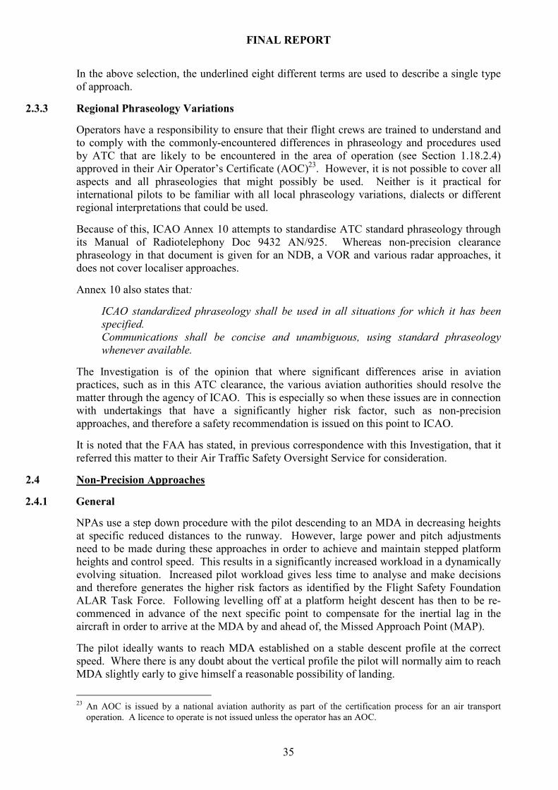
FINAL REPORT
35
In the above selection, the underlined eight different terms are used to describe a single type
of approach.
2.3.3 Regional Phraseology Variations
Operators have a responsibility to ensure that their flight crews are trained to understand and
to comply with the commonly-encountered differences in phraseology and procedures used
by ATC that are likely to be encountered in the area of operation (see Section 1.18.2.4)
approved in their Air Operator’s Certificate (AOC)23
. However, it is not possible to cover all
aspects and all phraseologies that might possibly be used. Neither is it practical for
international pilots to be familiar with all local phraseology variations, dialects or different
regional interpretations that could be used.
Because of this, ICAO Annex 10 attempts to standardise ATC standard phraseology through
its Manual of Radiotelephony Doc 9432 AN/925. Whereas non-precision clearance
phraseology in that document is given for an NDB, a VOR and various radar approaches, it
does not cover localiser approaches.
Annex 10 also states that:
ICAO standardized phraseology shall be used in all situations for which it has been
specified.
Communications shall be concise and unambiguous, using standard phraseology
whenever available.
The Investigation is of the opinion that where significant differences arise in aviation
practices, such as in this ATC clearance, the various aviation authorities should resolve the
matter through the agency of ICAO. This is especially so when these issues are in connection
with undertakings that have a significantly higher risk factor, such as non-precision
approaches, and therefore a safety recommendation is issued on this point to ICAO.
It is noted that the FAA has stated, in previous correspondence with this Investigation, that it
referred this matter to their Air Traffic Safety Oversight Service for consideration.
2.4 Non-Precision Approaches
2.4.1 General
NPAs use a step down procedure with the pilot descending to an MDA in decreasing heights
at specific reduced distances to the runway. However, large power and pitch adjustments
need to be made during these approaches in order to achieve and maintain stepped platform
heights and control speed. This results in a significantly increased workload in a dynamically
evolving situation. Increased pilot workload gives less time to analyse and make decisions
and therefore generates the higher risk factors as identified by the Flight Safety Foundation
ALAR Task Force. Following levelling off at a platform height descent has then to be re-
commenced in advance of the next specific point to compensate for the inertial lag in the
aircraft in order to arrive at the MDA by and ahead of, the Missed Approach Point (MAP).
The pilot ideally wants to reach MDA established on a stable descent profile at the correct
speed. Where there is any doubt about the vertical profile the pilot will normally aim to reach
MDA slightly early to give himself a reasonable possibility of landing.
23 An AOC is issued by a national aviation authority as part of the certification process for an air transport
operation. A licence to operate is not issued unless the operator has an AOC.

FINAL REPORT
36
If the aircraft arrives at the MDA too late, it is too high to land and stop on the runway and it
must therefore perform a Go-around. The advent of larger and less manoeuvrable air
transport aircraft with bigger engines and slower acceleration times has compounded these
problems. The result, therefore, is that where the pilot becomes unsure of his along track
position, there can be a tendency in VMC to increase the rate of descent in order to ensure
avoiding a later Go-around. This is especially so where the runway is relatively short for the
aircraft.
2.4.2 Development
NPAs were originally developed by flying to and/or from ground-based radio aids using a
step down platform system to control the vertical profile. Timing was used to estimate
distance to the runway threshold and advisory rates of descent being based on groundspeed.
This NPA system is still used on approach charts where horizontal information may be
provided by a navigation aid but the vertical flight path is usually a discontinuous series of
descents. In addition, older, non-FMS equipped aircraft do not have the capability to generate
an accurate distance to run to the runway; consequently an exact along track position is not
available. Because of this, the flightcrew’s knowledge of their vertical position in relation to
the required vertical flight path angle is always inaccurate to some extent. It is therefore not
surprising that non-precision approaches have a higher intrinsic risk factor than precision
approaches e.g. ILS approaches. Although some NPAs have associated DMEs, the DME is
often not referenced to the runway threshold, as in this case, and can therefore be an
additional source of calculation error.
In modern aircraft equipped with FMS, such as this aircraft, the FMS computes the position
of the aircraft continuously and accurately and therefore the distance to the runway threshold
is available if selected. Theoretically, the pilot can roughly calculate in advance the height
required at each mile distance from the runway. However, this assumes that he is aware in
advance that this information may be required, as was not the case in this incident. It also
assumes that the information he is working from is accurate and, in addition, there is the
possibility that there may be significant errors in such calculations performed under time
pressure, as happened in this occurrence. Ideally, the pilot wants to fly an NPA using a
constant descent profile with sufficient information to regularly determine and correct his
vertical flight path. Such information is not provided in current published State approach
charts. The Operator subsequently informed the Investigation that it had contracted Jeppesen
to include recommended crossing altitudes (derived) on all approach plates.
2.4.3 Technology Induced Constraints
In older technology aircraft, following a change of approach procedure, one pilot flew the
aircraft while the other set up the required navaids following which a mutual briefing was
held to ensure unanimity of view.
There are distinct advantages to FMS equipped aircraft, in holding accurate approach data in
its database, but the correct approach must be selected and the FM predicted flight path
crosschecked against the published approach chart. Each pilot must then verify the
significant items of information contained in the approach database while the other monitors
the flight of the aircraft. Following this, a mutual briefing is held. Normally this process is
completed well before the approach is commenced. In this case, that did not occur due to the
late ATC clearance.

FINAL REPORT
37
Although this process substantially reduces potential errors in setting up an approach, it is
time spent in activity that removes the attention of each pilot from monitoring the aircraft’s
flight path for a longer period. That time has become longer as technology has improved.
The PNF alluded to this in his interview by his experiments with the time taken to change an
approach procedure. The PNF stated that he could not physically make the changes required
in less than about 20 seconds. This did not include crosschecking the approach and Go-
around path in the FMGC. This coupled with preparing for the movement of the aircraft post
landing meant the PNF was out of his direct monitoring function for a period.
The distance from NOLEN to RIDGE is 8.6 nm. At a speed of 140 kts the aircraft would
have taken over 3.5 minutes to reach RIDGE. Assuming the PNF monitored the PF setting
and commencing the correct flight path angle, he should still have had time to return to
monitoring the aircraft and seeing the deviation. However, he was not expecting problems.
When interviewed later by the Investigation the PNF could not recollect what preoccupied
him during that critical period, but it was most likely briefing himself for post landing
activity.
2.4.4 Training Issues
The Operator’s training policy teaches correctly that the safest and most consistent way to fly
a non-precision approach is by flying a stabilised approach with a constant descent profile
that complies with obstacle clearance heights. The PF stated that he had not practiced NPA’s
with intermediate platform heights as the method trained by the Operator is to use a steady
rate of descent from the final approach fix (in this case RIDGE) to arrive at the MDA at, or
slightly before, the missed approach point. When questioned as to why he had not complied
with the 2,200 ft platform restriction the PF appeared to the Investigation to consider that the
requirements to fly a stabilised approach with a constant descent profile took precedence over
platform heights. Neither was the requirement to conform to platform heights readily
apparent in the interview with the PNF.
The Operator’s SOPs clearly identify that minimum or “hard altitudes” should be called by
the PNF during the approach but this did not happen in this incident. Although the Operator
subsequently informed the Investigation that its simulator training sessions normally include
NPAs, the event coupled with the pilot interviews leads the Investigation to believe that there
is a training issue involved. The Operator subsequently supplied details of its forthcoming
training programme to the Investigation. The training programme, both ground school and
simulator, addresses minimum altitude issues and also covers the reintroduction of managed
non-precision approaches due to its navigation database approval (see Section 1.18.10.5).
The Investigation notes that the Operations Manual, Part A 8.7, specified that the pilot shall
aim for a 3º glidepath. It did not provide guidance for those occasions where the glidepath
was not 3º, e.g. KORD RWY 22R. The Operator has subsequently published guidance and a
worked example for flightcrew that removes ambiguities regarding descent profiles. This has
also reinforced the requirement to observe minimum procedure altitudes (“hard heights”)
when conducting NPAs. In view of these measures, no Safety Recommendation is made.
2.4.5 Approach RWY 22R Vertical Profile
There is a difference in the type of information provided on a non-precision approach from
that provided on a precision approach regarding the vertical profile:
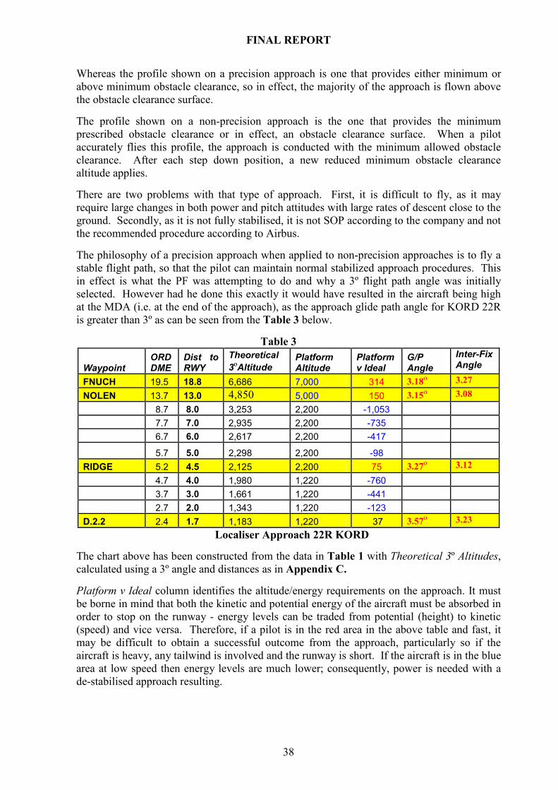
FINAL REPORT
38
Whereas the profile shown on a precision approach is one that provides either minimum or
above minimum obstacle clearance, so in effect, the majority of the approach is flown above
the obstacle clearance surface.
The profile shown on a non-precision approach is the one that provides the minimum
prescribed obstacle clearance or in effect, an obstacle clearance surface. When a pilot
accurately flies this profile, the approach is conducted with the minimum allowed obstacle
clearance. After each step down position, a new reduced minimum obstacle clearance
altitude applies.
There are two problems with that type of approach. First, it is difficult to fly, as it may
require large changes in both power and pitch attitudes with large rates of descent close to the
ground. Secondly, as it is not fully stabilised, it is not SOP according to the company and not
the recommended procedure according to Airbus.
The philosophy of a precision approach when applied to non-precision approaches is to fly a
stable flight path, so that the pilot can maintain normal stabilized approach procedures. This
in effect is what the PF was attempting to do and why a 3º flight path angle was initially
selected. However had he done this exactly it would have resulted in the aircraft being high
at the MDA (i.e. at the end of the approach), as the approach glide path angle for KORD 22R
is greater than 3º as can be seen from the Table 3 below.
Table 3
Waypoint ORD DME
Dist to RWY
Theoretical
3ºAltitude Platform Altitude
Platform v Ideal
G/P Angle
Inter-Fix Angle
FNUCH 19.5 18.8 6,686 7,000 314 3.18º 3.27
NOLEN 13.7 13.0 4,850 5,000 150 3.15º 3.08
8.7 8.0 3,253 2,200 -1,053
7.7 7.0 2,935 2,200 -735
6.7 6.0 2,617 2,200 -417
5.7 5.0 2,298 2,200 -98
RIDGE 5.2 4.5 2,125 2,200 75 3.27º 3.12
4.7 4.0 1,980 1,220 -760
3.7 3.0 1,661 1,220 -441
2.7 2.0 1,343 1,220 -123
D.2.2 2.4 1.7 1,183 1,220 37 3.57º 3.23
Localiser Approach 22R KORD
The chart above has been constructed from the data in Table 1 with Theoretical 3º Altitudes,
calculated using a 3º angle and distances as in Appendix C. Platform v Ideal column identifies the altitude/energy requirements on the approach. It must
be borne in mind that both the kinetic and potential energy of the aircraft must be absorbed in
order to stop on the runway - energy levels can be traded from potential (height) to kinetic
(speed) and vice versa. Therefore, if a pilot is in the red area in the above table and fast, it
may be difficult to obtain a successful outcome from the approach, particularly so if the
aircraft is heavy, any tailwind is involved and the runway is short. If the aircraft is in the blue
area at low speed then energy levels are much lower; consequently, power is needed with a
de-stabilised approach resulting.
FINAL REPORT
39
The G/P Angle column identifies the descent angle of the platform heights for the published
non-precision localiser approach to RWY 22R at KORD. Although the published glide slope
angle is 3º, and that is the only vertical profile angle information available to the pilot,
calculation shows that at the Final Approach Fix RIDGE the glidepath is 3.27º and at D2.2 it
is 3.57º. This is reflected by platform heights on the Jeppesen approach chart showing above
the glide slope, at RIDGE, at D2.2 and at Minima on the approach chart. In addition, the
inter-fix angles confirm that picture. It is noted that there is no visual depiction of an NPA
flight path on the AIP chart.
As the FPA selector of the aircraft is calibrated to a tenth of a degree and aircraft can fly to
that level of accuracy, the Investigation is of the view that the published final glide slope
angle should reflect reality. As the approach procedure has been constructed in accordance
with TERPS and, as all the fixes are movable reference positions, the Investigation is
unaware of any reason why the approach cannot be designed to provide a singular flight path
angle and so facilitate stabilised approaches. The Investigation therefore believes that the
FAA should review the KORD RWY 22R published glide slope and glidepath design.
Graphic 5
Extract Jeppesen 21-8 KORD ILS RWY, Appendix A
The visual picture presented on the approach chart is quite distracting and confusing to a pilot
unsure of his vertical flight path. In examining the approach chart non-precision vertical
profile, the aircraft is depicted as high at both RIDGE and D2.2, if it maintains platform
heights. This visual depiction is correct, as was borne out by the analysis of the flight path.
However it is confusing, especially to a pilot who intends to perform a stabilised 3º glide
path, in accordance with his SOPs. At a quick glance all he knows is that if he follows the
platform altitudes he will be high, and that is not a good option when faced with a short
runway. It is possible that this confusion contributed to the pilot’s decision to ignore the
platform height at RIDGE and concentrate on his height/distance profile, which he had
incorrectly calculated.
It is noted that on the Airbus A330 during NPAs for both VORs and NDBs a pseudo glide
path is generated by the FMGC. This can be used in managed guidance in accordance with
the guidance conditions outlined in Section 1.18.10.2 thus improving flight path stability and
safety. However, the manufacturer states that non-precision localiser approaches should be
flown in lateral (LOC) and vertical (FPA) guidance.
The Investigation questions why such a useful tool as the pseudo glide path is not made
available for localiser approaches. This could provide the ability to perform these approaches
more safely due to much better awareness of the flight path of the aircraft relative to the
correct vertical profile and accordingly a Safety Recommendation is issued requesting the
manufacturer to review the case.

FINAL REPORT
40
2.5 Approach Preparation
2.5.1 General
In addition to laterally tracking the navaid and flying the aircraft, the pilot tactically needs to
continually assess his vertical trajectory during the approach. Because of the difficulty of this
exercise, when combined with the normal handling of the aircraft and ATC, checklists, etc,
pilots strategically try to prepare in advance for non-precision approaches by careful
briefings. Many pilots draw the approach or a table with calculated checkpoint heights and
distances for the final segment of the descent as an aide memoir. This process is normally a
fully coordinated flightcrew approach where the shared strength and experience of its
individuals are brought to bear and errors eliminated.
2.5.2 Vertical Profile Estimation
SOPs require the PNF to call out recommended or hard altitudes for each nautical mile of the
approach. Although the SOPs of the operator specify this requirement no guidance or
examples on how this should be calculated is provided.
During a normal approach, an aircraft descends about 300 feet for each nautical mile on a 3°
glide path. This rule of thumb enables the pilot to mentally calculate whether he is high or
low on the flight path e.g. if an aircraft is at a distance of 3 nm from landing the height above
the ground should be 900 feet. In addition, the height calculated must be adjusted by runway
threshold elevation to give altitude. Finally, the pilot compares this reference altitude with
the aircraft’s altimeter to determine if he is high or low on the vertical profile. If the DME is
located at the touchdown point then its readout can be used directly. If it is not, as at KORD
22R, then the DME readout has to be adjusted by its distance from the touch down point.
Where the altitudes/distances are not promulgated and the glide slope is not a 3º angle, the
calculation becomes more complex. In addition, mental calculations in themselves are
fallible, especially in the heat of the moment when the additional demands of operating the
aircraft are to hand. Therefore, it seems appropriate that a table of distances versus heights
should be published on all charts that might potentially be used for a non-precision approach,
thereby eliminating such errors, and a Safety Recommendation is issued to ICAO to that
effect. The Operator has informed the Investigation that a table of distances versus heights
has been implemented on their US approach charts (using Jeppesen-derived data), although
published data does not include this.
2.5.3 Human Factors
2.5.3.1 General
The fact that there were no adverse preconditions may have assisted in lulling the flightcrew
into a false sense of security during the approach as no problems were expected. The two
experienced pilots expected a simple ILS, the automatic flight systems were reliable and the
weather was fine. With autopilot and autothrottle engaged the PF role is essentially
monitoring the automatic flight of the aircraft to ensure it conforms to the pre-checked flight
path. However, a sudden change to an approach changed the PF role completely - from
monitoring to actively controlling a different flight path and with little time to prepare. It is
probable that, after the long flight, flightcrew arousal levels were relatively low and therefore
performance was affected. There was initial uncertainty about the clearance, both from its
unfamiliar phraseology and meaning, which was not clarified.

FINAL REPORT
41
The late and unusual approach clearance by ATC did not allow adequate time to brief for the
approach. As a result, the flightcrew had no pre-shared understanding or plan regarding the
approach procedure. Normal SOPs ensued, with the PNF checking approach charts and
setting up the FMGC for the new approach and the PF actively using selected vertical
parameters to control the aircraft.
A crew resource management (CRM) issue arose when the PF changed the flight path, while
the PNF was not monitoring, and the PNF stated the PF did not communicate that fact to him.
The PNF stated that he did not observe the change, as he was otherwise occupied, possibly
distracted by other duties.
2.5.3.2 Clearance Clarification Difficulty
Annex 2 (Rules of the Air) allows the pilot, when unsure, to request clarification of an ATC
clearance but this does not always happen in reality. The reasons for this can vary from
inexperience, lack of confidence and possible loss of face, to lack of opportunity in a busy
ATC environment as mentioned previously.
A pilot should question any clearance that he has doubt about and get a clear, factually correct
picture of what is intended by the controller. If not clarified immediately a pilot must make
some assumption about a clearance, as the aircraft continues at speed, and then act on that
basis. Frequently any procrastination in immediately questioning the clearance results in the
opportunity being lost as concentration becomes focused on the developing approach and an
initial assumption then becomes an established fact. However, as in this case, there is usually
an element of residual doubt that may distract the pilot and detracts from the normal level of
confidence with which he should perform. In a multi-crew situation, other factors such as a
cross-cockpit command gradient may also have a heavy influence on flightcrew decision to
clarify. There is no evidence that this latter factor was at play here, just the initial uncertainty
generated and a possible subsequent distraction factor.
2.5.3.3 Approach
SOPs for the approach require the PNF to call out recommended altitudes for each nautical
mile of the approach. These were not published on the approach chart and the flightcrew had
inadequate time to prepare them in advance. Where this is the case, SOPs recommend using
the PROG page on the MCDU to check height versus distance profile. The PF did this, but
incorrectly. The PNF was out of the loop and was not monitoring the vertical profile. Thus,
the SOP recommendation was not complied with.
The descent profile should have been in accordance with the published platform height at
RIDGE. This fix is DME based and would appear as a symbol in the PF’s display. It is
probable that the PF was not paying attention to the obligatory DME but more to the FMGC
distance to go and trying to acquire the runway visually. This error is simple to make in an
aircraft with so much information available and for processing that task prioritising is
essential.
There is also the issue of the PF increasing the rate of descent substantially but the PNF being
unaware of it. The Investigation notes that the hand of the PF over the FPA controller may
mask a change in selection from the PNF, if the PNF is in the right hand seat. Therefore it is
important for a pilot to communicate any change in selection as otherwise the change is only
detected by a change of angle displayed on the PFD and then later, a change in rate of
descent. During both pilot interviews, the emphasis on maintaining a stabilised descent flight
path during an NPA appeared uppermost in the mind-set of both pilots.
FINAL REPORT
42
Consequently, an approach, such as KORD 22R, which has different inter-fix angles and
three platform heights, two of which appear in the chart as above the 3º glide slope, would
have clashed with this mind-set. In reality, both goals are incompatible. If there had been
adequate time to brief for this approach, such issues could have been discussed and resolved
and the pre-approach briefing would have improved the CRM performance of the flightcrew,
as there would have been a shared mental concept.
2.5.3.4 Go-Around
The data shows that the PF initially applied MCT power for 5 seconds, followed by TOGA
thrust for 4 seconds but reduced this subsequently to manual thrust. The result of selection of
TOGA is that the FMGC goes to Go-around mode where the command bars indicate the
overshoot pitch attitude required and the navigation system indicates the Go-around path to
be followed with the previously flown approach added. Speed is then referenced to minimum
drag speed and power increases to maximum. Exiting from this mode is not simple.
It is unclear if the PF ever really made a decision to Go-around. What appears more likely is
that the PF may have thought about it but, during his hesitation, the PNF realised what was
wrong by checking the RADALT versus the distance to go and deduced that they were low
early - a useful check since the terrain was flat. Although the PF appears to have been
indecisive, in whether to Go-around or not, a final decision to level off was suggested by the
PNF and the balance of decision-making swung to that side of the cockpit as the suggestion
was adopted by the PF.
2.5.3.5 VFR Approaches
To some extent, this was essentially a visual approach under Instrument Flight Rules, as a
visual approach was flown while using an NPA procedure for 22R. Visual approaches are
familiar territory for an airline crew as there are occasions when approaches are conducted
under VFR, varying from practice visual approaches and landings to when approach aids fail.
Good airmanship requires that a pilot practice his range of skills including VFR visual
approaches. If conducting a visual approach, descent should not be below a height of 1,000 ft
over the ground until a 3º glide path is intersected and thereafter the descent should be on the
glide path. A too early descent, in addition to obstacle clearance problems, also causes
environmental noise problems when a large aircraft is flown closer to the ground than
necessary, which is poor airmanship.
2.5.3.6 Visual Factors
As the approach was conducted in the late afternoon in the autumn, it is probable that the
runway approach lights and the airport itself would have been difficult to identify at a
distance even though the visibility was probably in excess of 10 miles (Appendix B Photos 1
& 2). The former was due to the southwesterly approach into diffused sun light and the latter
due to lack of terrain colour contrast at that time of year.
In addition, having got low on the glide slope, the runway would have been harder to identify,
as it would not appear in the normal or expected position in the cockpit windows. That low
view is not one most pilots are accustomed to, as they are used to the view presented when
approaching on a normal 3º glide path angle. As the aircraft got progressively lower, the
view of the approach area would deteriorate and the runway would become more difficult to
identify.
FINAL REPORT
43
2.5.4 Crew Resource Management (CRM)
It was not a good crew performance from a CRM aspect, from the errors of the PF to the
distraction or possible complacency of the PNF. Yet, many pilots have found themselves in a
similar position at some stage in their flying career. When unprepared for an approach, or
prepared for a different approach, a large change has to be made in strategic thinking and
leadership is needed to ensure effective teamwork and functioning. Priorities need to be
established and workload allocated - the first priority being flying the aircraft and keeping it
safe. As a result attention and awareness are directed and dispersed among concurrent tasks;
flying, adjusting procedures and navaids, calculating and setting new MDA, etc.
There is a limit to working memory and cognitive capacity, which, as approached, reduces the
spare capacity for strategic thinking, planning ahead and analysing current tasks and results.
As overload approaches these higher-level analytical facilities yield to more tactical tasks and
a reactive situation develops which erodes safety margins. Tactics that have priority in an
NPA are tracking the inbound bearing while keeping aware of the vertical profile required by
calculating the distance/height relationship using mental arithmetic. If things do not happen
as expected then mental overload can occur. In an overload, pro-active strategic management
of the flight is dropped and the pilot just reacts to the developing situation. Situational
awareness becomes less and judgement is consequentially impaired. There is some evidence
for this in the poor communications, false hypotheses and indecision of the PF while
assessing the situation. Similarly, working memory limitation may have required the PNF to
revise the airport details shortly before landing so that he was familiar with the possible ATC
clearances that might ensue after landing. This may partly explain why the PNF did not
observe the change in descent rate during the approach.
The other routes flown by the Operator are to airports whose altitudes are close to sea level.
Therefore, airport altitude is not normally a factor in calculating the height loss required
during the approach. This possibly explains why the PF forgot to include runway height in
his calculations. A further consideration is that the PF had been originally trained in and had
used QFE procedures for much of his career. In a QFE approach, the altimeter indicates the
height of the aircraft above the airport and airport elevation correction is not required.
It is of interest that there appears to have been little discussion of the incident by the
flightcrew after the occurrence. Subsequently the PNF was not aware that a report had not
been submitted again indicative of a communication problem. It is probable that, if
communications between the flightcrew had been better, the incident would have been
detected at an early stage by the PNF who was unaware of what the PF was doing and was
“out of the loop”.
The Operator has informed the Investigation that its CRM courseware is being modernised
and updated with a project pilot tasked with leading this review. The project pilot has been
selected and further training has been scheduled at a facility abroad. A recurrent CRM
training module for all pilots will include inter-pilot communication requirements.
2.5.5 Reporting of Incident
Rules of the Air required that a height control error of more than 300 feet be reported. In
addition, ICAO states that if any event occurs that might provide useful information for the
enhancement of air safety it should be reported. The approach was stabilised but there was a
substantial altitude deviation below the platform height. Operator procedures state that if a
Commander is in any doubt an incident signal should be raised.
FINAL REPORT
44
The confidential report submitted by the PF showed he believed he was 1,000 ft high through
much of the approach. This is at variance with FDM data. The aircraft was on the correct
vertical profile at NOLEN but got progressively below it afterwards. The confidential report
stated that the aircraft arrived at 100 ft above minima at 3 nm when it was in fact 180 ft above
minima at 4 nm. It did not mention the platform altitude deviation at RIDGE. Otherwise, the
report accurately reflected both pilots’ interviews and FDM data. The PF stated he did not
initially believe that an incident had happened, as he believed he was high during the
approach.
However, the PF stated that when he saw the FDM data he realised the occurrence should
have been formally reported. The PF had the ability to request a copy of the FDM data for
his flight in order to clarify the occurrence. This facility is rarely used by Line Pilots. The
reason for this is discussed in Section 2.6.5.
Therefore, the PF neither reported the incident nor sought clarification of the occurrence but
went to the ASO to discuss the matter. It is significant that of the three reporting options the
PF chose an option that resulted in his flight being de-identified. When questioned about this
he indicated he felt the ASO was an appropriate forum for what he believed to be an air safety
incident as he felt if it happened to him, it could happen to anyone. He did not realise how
circumscribed that non-executive function was, in its ability to act, until he afterwards read
the details of the confidential system in the ASM.
2.5.6 Confidential Report
Confidential reporting is used by many organisations and is internationally recognised as a
useful tool in safety management. In this case, however a confidential report was accepted by
the ASO on an operational incident that should have been reported through the executive
management function. It was accepted because the seriousness of the deviation was
underestimated by the reporter and the HAS was unable to check FDM flight parameters, due
to the terms of the confidentiality system. Even if he had been able to do so, it is doubtful if
the HAS would have been able to correctly assess the report due to lack of operational
experience, or access to such experience, by any of the staff members of the ASO.
There is also the issue that whereas the ASM gives examples of incidents that may be
reported through the non-punitive incident reporting system, no guidance is given regarding
incidents that should not be reported by a confidential report. If a confidential report is made
concerning a mandatory reportable occurrence then the ASO, as a function of the company, is
required to report what it knows about the incident, including the identity of the reporter.
There are cases where such incidents are reported confidentially and anonymously, e.g. by
telephone, Internet etc. In these cases, the ASO must still report the matter, if it is satisfied
about the validity of the report, even though it cannot identify the reporter.
In addition, having submitted the de-identified report to Flt. Ops, there was no facility to
provide any further feedback, even though the PF would have been willing to provide it.
Although the ASM states that the HAS has absolute discretion in handling the confidential
report, the ASO operates within an integrity system and any breach or perceived breach of
integrity by an ASO would be extremely counterproductive, especially where no guidance is
given. Therefore, the Investigation believes that the facility should be provided, within the
confidential system, through the ASO to forward a query from management to the
confidential reporter who may answer it on a voluntary basis. It also recommends that
guidance should be provided in the ASM as to what is acceptable in a confidential report and
what is a reportable occurrence.

FINAL REPORT
45
Consideration should also be given to allow those within the ASO with suitable operational
expertise to promptly check FDM occurrences within the terms of the confidentiality system.
The Investigation therefore recommends that the Operator review the guidelines and
operating procedures of its confidential reporting system.
2.6 Operator’s Safety Management System
2.6.1 General
The Operator’s Air Safety System functions through normal operational reports being
collected and investigated by the executive management. Here the routine line problems are
addressed. In cases of accidents or incidents, the event will also be investigated by the ASO,
which monitors the overall functioning of the line Departments. Critically, as with normal
airline practice and in line with the guidelines in the ICAO SMM, the ASO reported directly
to top management, in this case the Chief Executive where the ultimate responsibility for a
safe operation lies.
The Air Safety System is not just a function of the Air Safety Office. It extends from staff
culture and ethos, to SOPs and operational training, to monitoring compliance and
investigating events by the executive management and to the overview exercised by the ASO.
The report of this occurrence was made not through the normal reporting channel but through
a confidential system that served to both mask and delay its investigation. However,
management were aware that such a report was in the system due to the transcript of the
confidential report submitted by the HAS. Although aware of the report
Flt. Ops management did not know how substantial the deviation was and were not in a
position to determine its severity. Ultimately the strength of a system is how it deals with the
exceptional and here the Operator’s Air Safety System failed to identify and deal with the
incident in a timely manner.
2.6.2 Occurrence Reporting
This particular case does not fall into the normal pattern of operational incidents, as the PF
was unsure if an incident had occurred and probably hoped one had not. If that were the case,
the pilot would be unlikely to want to check FDM data to see if an incident had occurred that
warranted mandatory reporting. This is especially so as he would have, in accordance with
the DGSA, to initially submit a written request stating why. If he was in any doubt, he should
have reported the event as required by Air Regulations, the Operator’s Operations Manual
and the DGSA. Incident Signals concerning events in Category A and B, as defined in the
Operator’s procedures, must be discussed, before transmission, with the Chief Executive.
However, legislation requires the commander, or pilot-in-command, to report any such
occurrence promptly to the authorities. The legal onus is on the pilot. It is only where the
pilot is incapacitated or otherwise unavailable that the responsibility defaults to the company.
It is noteworthy that the Operator’s Operations Manual Part A section 1.1.1 initially states
that fact. However, it subsequently outlines procedures and details of how the commander
notifies its operations base and thereafter all procedures are internal company related. There
are no further details given in the Operations Manual of how the commander may notify or
contact the appropriate authorities24
.
24 Notification of Authorities procedures are detailed in the ASM.

FINAL REPORT
46
In practice, however most operators fulfil that function on the part of their pilots in the
interests of speed and efficiency as the pilot may be otherwise occupied. In addition, as
airlines operate internationally local procedures may vary from place to place and therefore
the operator’s local representative, if any, may be in a better position to fulfil that function.
However, there appears to be no procedural feedback loop to the commander to inform him if
or when his mandatory obligation has been complied with.
The Operator has subsequently amended its Operations Manual to comply with Mandatory
Occurrence Reporting Procedures and to provide the commander with appropriate guidance
concerning immediate notification of reportable events to the appropriate authorities. In view
of this no safety recommendation is considered necessary.
2.6.3 Air Safety Office (ASO)
The Investigation notes that although the Operator’s ASO conforms in principle to the
guidance of the ICAO Safety Management Manual its specifics do not. In the ICAO SMM,
reference is made to a Safety Office whereas the Operator has an Air Safety Office. It is
surprising therefore, that none of the staff in the office has any experience either as a pilot or
as a cabin-crew member.
In addition, investigative training has been provided to the HAS alone. Although one of the
staff had crisis management training this is more relevant to post accident/incident
management than preventing it, which is the function of the Air Safety Office. The
Investigation therefore considers that the ASO should have access to flying and operational
expertise within its office.
The Investigation believes this lack of skill sets and training in an essential airline function is
inappropriate. However, the Investigation is satisfied that the HAS completed his duties
responsibly and in accordance with the Operator’s procedures.
Since the incident the Operator has restructured Safety Management within the organisation
and the ASO function. It has assigned additional staff to the ASO including a current line
pilot and an additional technical investigator. Training scheduled will include ICAO SMS
courses and Air Accident Investigator courses. In view of this no Safety Recommendation is
required.
2.6.4 Air Safety Manual (ASM)
The ASM is an important document where a core operating ethos of an airline is published.
Here operating philosophy and policies are outlined, standards delineated and how accidents
and incidents are managed is stated. The document also covers the oversight functions of the
ASO, the duties of its HAS and his reporting lines. The duties of the HAS regarding the
confidential system are discussed in Section 2.5.5 in which there are recommendations that
affect the ASM.
In addition, the ASM categorises accidents, incidents and occurrences. This covers both
mandatory and other relevant occurrences. It is noted that this categorisation did not conform
to occurrence legislation in force at the time.
It is noted that neither the management chart in 1.3 nor management functions chart in 2.1.5
were up to date with organisational change.

FINAL REPORT
47
The Investigation has been subsequently informed that Mandatory Occurrence Reporting
guidance material has now been included in the Operator’s Operations Manual and that the
Operator has amended ASM Part 2.9.4 to address the above deficiencies.
2.6.5 Flight Data Monitoring System (FDM)
The Investigation notes that the FDM system, structures and its associated agreement in use
by the Operator complies fully with the guidance for such systems as issued by ICAO in its
Safety Management Manual, Doc 9859 and identified in Section 1.18.6.
However, the Investigation was concerned with the length of time taken from data being
recorded on board during an occurrence to when that event was identified by FDM analysis
and subsequently investigated. That length of time was due to the following factors:
1. The PCMCIA method of recording the data required physical transfer of the data.
2. The monthly procedural method of collecting the data, as aircraft were available.
3. Analysis meetings were held monthly.
4. Although not a factor in this incident, the possible unavailability of the Link person to
feedback information on the occurrence could introduce a further delay.
As data was collected monthly, an event of interest may have been recorded at the beginning
of that monthly cycle. In addition, as data was only removed while the aircraft was at base
that too took time. Following this, the data was analysed and finally the triggered event came
before the Review Group. It is probable that the average time period from occurrence to
initial analysis by the group was in the order of six weeks. By that time most records
concerning the flight were discarded. Therefore, it was not possible to investigate a FDM
incident within a reasonable timescale.
Subsequent to the incident, the Investigation has been advised that the Operator is modifying
its complete fleet to provide instantaneous download of FDM data to base post flight. This
system uses microwave technology to download the compressed and encrypted data with the
result that FDM data is available for screening immediately following a flight. The net effect
of this is to reduce the Operator’s FDM screening and analysis time by over a month
therefore no Safety Recommendation is required specific to data handling.
2.6.6 Data Gathering System Agreement (DGSA)
The DGSA regulates the operation of the FDM programme within the airline. The
Investigation notes that this agreement is according to ICAO guidance Doc 9859. The airline
uses this monitoring program as part of its Accident Prevention and Flight Safety Program.
The program is non-punitive and contains adequate safeguards to protect the source of the
data.
The DGSA provided for monthly meetings of the Review Group. By the time the Review
Group met other recorded data and information associated with the incident was no longer
available. Generally, that was not a problem as the primary function of the FDM is to
monitor trends. However, on occasions such as this incident, specific action may need to be taken much
faster. The monthly meeting structure of the DGSA inhibits that ability, as the DGSA has no
provisions to speed the process. Therefore the DGSA needs to be amended to incorporate
this ability. In addition, the occurrences listed in this document are no longer in line with the
recent mandatory occurrence reporting requirements as outlined in Section 1.18.4.

FINAL REPORT
48
A similar restriction to that in the ASM is found in paragraph 3.4.1.1 - that Incident signals on
serious events must be discussed, before transmission, with the Chief Executive. The
Investigation is of the view that, whereas this may be appropriate in internal company
interface procedures, the clause is not appropriate where statutory obligations exist.
The DGSA, in paragraph D.14, permits the pilot to apply in writing (stating reasons) to view
FDM data from his flight, but he can only do this with the permission of other pilots on the
flight. Having formally requested the data in writing, he must state the reasons why. The
Investigation believes that these restrictions are unduly cumbersome and inhibits pilot
analysis of their flights and in-flight events.
The Investigation therefore recommends that both parties review the DGSA to enable
speedier identification and investigation of operational incidents, to make it compatible with
current mandatory reporting requirements and to facilitate pilot analysis of their particular
flights.
3. CONCLUSIONS
(a) Findings
1. The aircraft was properly certified for the purpose of the flight.
2. The flightcrew were properly licensed with valid medicals.
3. The flightcrew were both experienced and familiar with the aircraft.
4. Meteorological conditions are not considered a factor in this incident.
5. There were no operational or equipment problems with the aircraft.
6. The ILS glide slope on RWY 22R at KORD failed before the aircraft commenced its
approach.
7. The ATC controller gave a clearance for an “ILS 22R – Glide slope unusable” shortly before
the approach commenced.
8. The flightcrew were unfamiliar with this clearance and it caused uncertainty.
9. This non-precision approach ATC clearance was in accordance with applicable FAA
phraseology guidelines.
10. International ICAO phraseology guidance is not published for an instrument non-precision
localiser approach.
11. Non-precision approaches on FMC equipped aircraft take more time to setup than on older
technology aircraft.
12. The PF initially set a 3º flight path angle, in accordance with procedures, but increased it
inappropriately due to an erroneous calculation.
13. The PF did not communicate this higher selection to the PNF contrary to good crew resource
management.
14. The PNF did not monitor the rate of descent as required.

FINAL REPORT
49
15. The aircraft descended during the approach to 774 ft below the platform height at RIDGE.
16. Following selection of TOGA, the PF did not continue the Go-around.
17. As VMC conditions prevailed, the PF elected to continue to land.
18. The aircraft subsequently landed without further incident.
19. The PF inappropriately reported the event through the ASO confidential reporting system.
20. The Operator provided no guidance to the ASO regarding its statutory obligation for
mandatory occurrence reporting of operational events when accepting a confidential report.
21. Lack of line operational experience in the Air Safety Office impeded its response to this
operational occurrence.
22. The delays, both individual and systemic, in reporting and detection of the incident were
excessive.
23. The FDM system, both data handling and support agreements, impeded the speedy analysis
and reporting of occurrences.
(b) Cause
1. The PF selected an incorrect rate of descent during the approach to RWY 22R at KORD due
to a miscalculation of height loss required.
(c) Contributory Causes
1. The approach was not properly monitored by the PNF.
2. The late change of approach by ATC, from an ILS to a non-precision localiser approach, did
not allow the flightcrew sufficient time to carry out a briefing for that particular type of
approach.
3. The ATC clearance phraseology used was unfamiliar to the flightcrew and may have
introduced uncertainty.

FINAL REPORT
50
4. SAFETY RECOMMENDATIONS
1. That standard ATC phraseology be agreed, through the agency of ICAO, for an Air Traffic
Control approach clearance for a non-precision localiser only, glide slope
inoperative/unusable approach and that such phraseology be included in the ICAO Doc 9432
AN/925. (SR 16 of 2008)
2. That ICAO introduce a PANS-OPS standard requiring that a table of altitude and distance to
go for each nautical mile, is published on instrument approach charts used for non-precision
approaches. (SR 17 of 2008)
3. That Airbus considers providing a pseudo glide path display on Flight Management
Computer equipped aircraft during non-precision localiser approaches. (SR 18 of 2008)
4. That the FAA reviews the published glide slope angle and platform altitudes for an
instrument approach to KORD, ILS RWY 22R. (SR 19 of 2008)
5. That the Operator reviews its Air Safety Manual to ensure compliance with Mandatory
Occurrence Reporting procedures. (SR 20 of 2008)
6. That the Operator and its pilots review their Data Gathering System Agreement to ensure that
it is compatible with current legislation and that it enables timely investigation of operational
incidents. (SR 21 of 2008)
Response:
The Operator has informed the Investigation that it accepts Safety Recommendation SR 20 of
2008 and SR 21 of 2008.

FINAL REPORT
51
Appendix A
Chart 1
KORD ILS Approach RWY 22R - Jeppesen Chart 21-8

FINAL REPORT
52
Appendix A
Chart 2
KORD Airport layout – Jeppesen Chart 20-9
In general, a traffic counter-flow system operated on the inner and outer taxiways. Circles
indicate where accidental runway incursions (Hot Spots) are likely and where extra vigilance
is required when taxiing.

FINAL REPORT
53
Appendix A
Chart 3
KORD ILS RWY 22R - FAA USA

FINAL REPORT
54
Appendix B
Photo No. 1
KORD RWY 22R Approach at 6 nm
Photo No. 2
KORD RWY 22R at 3 nm in good visibility

FINAL REPORT
55
Appendix C
KORD 22R Approach Slope Calculations
A 3º angle was assumed to commence at 55 ft over the runway threshold, which is the
Threshold Crossing Height (TCH) identified in the FAA TERPS manual for larger air
transport Group 4 aircraft.
Graphic 5
The Haversine formula, which is sufficiently accurate for this analysis, was used to determine
inter-fix distances from their geographic co-ordinates, this when summed resulted in
distances to the runway threshold. These international nautical mile distances were converted
to feet.
The elevations at the various fix distances were than calculated (distance x tangent 3º). The
TCH and RWY 22R altitude (55 + 651 = 706) were then added to give the Theoretical 3º
Platform Altitudes at the fix positions.
The platform altitudes at the various fixes were taken and this height divided by the distance
resulted in a slope, which was converted to a descent angle. This calculation was completed
for both the angle to the threshold crossing point and the inter-fix angles.
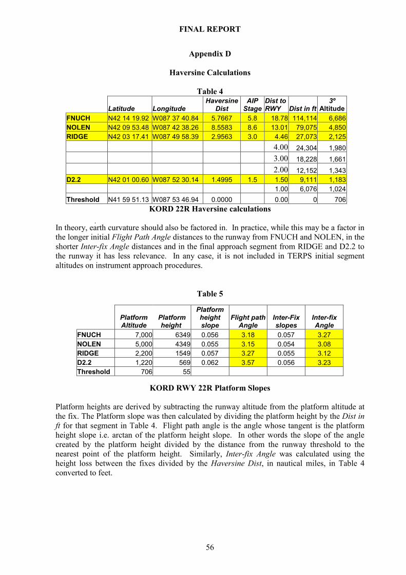
FINAL REPORT
56
Appendix D
Haversine Calculations
Table 4
Latitude Longitude Haversine
Dist AIP Stage
Dist to RWY Dist in ft
3º Altitude
FNUCH N42 14 19.92 W087 37 40.84 5.7667 5.8 18.78 114,114 6,686
NOLEN N42 09 53.48 W087 42 38.26 8.5583 8.6 13.01 79,075 4,850
RIDGE N42 03 17.41 W087 49 58.39 2.9563 3.0 4.46 27,073 2,125
4.00 24,304 1,980
3.00 18,228 1,661
2.00 12,152 1,343
D2.2 N42 01 00.60 W087 52 30.14 1.4995 1.5 1.50 9,111 1,183
1.00 6,076 1,024
Threshold N41 59 51.13 W087 53 46.94 0.0000 0.00 0 706
KORD 22R Haversine calculations
In theory, earth curvature should also be factored in. In practice, while this may be a factor in
the longer initial Flight Path Angle distances to the runway from FNUCH and NOLEN, in the
shorter Inter-fix Angle distances and in the final approach segment from RIDGE and D2.2 to
the runway it has less relevance. In any case, it is not included in TERPS initial segment
altitudes on instrument approach procedures.
Table 5
KORD RWY 22R Platform Slopes
Platform heights are derived by subtracting the runway altitude from the platform altitude at
the fix. The Platform slope was then calculated by dividing the platform height by the Dist in
ft for that segment in Table 4. Flight path angle is the angle whose tangent is the platform
height slope i.e. arctan of the platform height slope. In other words the slope of the angle
created by the platform height divided by the distance from the runway threshold to the
nearest point of the platform height. Similarly, Inter-fix Angle was calculated using the
height loss between the fixes divided by the Haversine Dist, in nautical miles, in Table 4
converted to feet.
Platform Altitude
Platform height
Platform height slope
Flight path Angle
Inter-Fix slopes
Inter-fix Angle
FNUCH 7,000 6349 0.056 3.18 0.057 3.27
NOLEN 5,000 4349 0.055 3.15 0.054 3.08
RIDGE 2,200 1549 0.057 3.27 0.055 3.12
D2.2 1,220 569 0.062 3.57 0.056 3.23
Threshold 706 55

FINAL REPORT
57
Appendix E
Glossary A/P Autopilot
A/T Auto-thrust
AAIU Air Accident Investigation Unit Ireland
AIM Aeronautical Information Manual - USA
AIP Aeronautical Information Publication, published by each country
ALAR Safety Foundation Approach and Landing Accident Reduction Task Force
AMSL Above Mean Seal Level
AOC Air Operator’s Certificate
ARINC Aeronautical Radio Incorporated: specifies standards for avionic equipment
ASM Air Safety Manual.
ASO Air Safety Office
ATC Air Traffic Control
ATS Air Traffic Services
B-RNAV Basic RNAV
CAA Civil Aviation Authority - UK
CFIT Controlled Flight Into Terrain
CRM Crew Resource Management
CSR Captain’s Special Report
CVR Cockpit Voice Recorder
DGSA Data Gathering Systems Agreement
DME Distance Measuring Equipment
EASA European Aviation Safety Agency - EU
ECAC European Civil Aviation Conference - Europe
EGPWS Enhanced Ground Proximity Warning System – aircraft system
EIDW Dublin Airport
EU European Union
FAA Federal Aviation Administration - USA
FAF Final Approach Fix
FARs Federal Aviation Regulations published by the FAA
FCI Flight Crew Instruction
FCL Flight Crew Licensing
FCOM Flight Crew Operating Manual - published by Airbus
FDA Flight Data Analysis - the same as FDM
FDM Flight Data Monitoring – a system used to monitor operational parameters
FDR Flight Data Recorder
FINAL APP An FMGC approach mode that provides both lateral and vertical guidance
Flt Ops Flight Operations Management
FM Flight Management – aircraft system
FMGC Flight Management Guidance Computer – a unit within the FM/FMS
FMS Flight Management System – aircraft FMS as a totality
FPA Flight Path Angle – the vertical descent or ascent profile in degrees
G/P Glide Path
G/S Glide Slope
GNSS Global Navigation Satellite System
GPS Global Positioning System
HAS Head of Air Safety
HDG Heading mode – aircraft navigation mode
IAA Irish Aviation Authority
IAP Instrument Approach Procedure
ICAC In-Close Approach Change - a late runway change by ATC
ICAO International Civil Aviation Organisation
IFR Instrument Flight Rules
ILS Instrument Landing System
INS Inertial Navigation Systems

FINAL REPORT
58
JAA Joint Aviation Authority
JAR(s) JAA Requirement(s)
KJFK New York Kennedy Airport
KORD Chicago O’Hare Airport
LOA Letter of Approval
LOC Localiser only mode – aircraft navigation mode
MAP Missed Approach Point
MCDU Multi Control Display Unit
MCT Maximum Continuous Thrust
MDA Minimum Descent Altitude
METAR Meteorological Actual Report
MOR Mandatory Occurrence Report
NAV FMGC Navigation mode
Navaid A ground based RF
ND Navigation Display
NDB Non Directional radio Beacon
NOTAM Notice to Airmen
NPA Non-Precision Approach
NTSB National Transportation Safety Board- USA
OPS Operations
PANS-ATM Procedures for Air Navigation Services – Air Traffic Management, ICAO
PANS-OPS ICAO approach design criteria
PCMCIA Personal Computer Memory Card International Association - a data card
PF Pilot Flying
PFD Primary Flight Display
PFR Post Flight Report
PNF Pilot Not Flying
P-RNAV Precision RNAV
PROG A FMGC Progress page that can be displayed on the MCDU
QAR Quick Access Recorder
QFE An altimeter barometric setting that displays the height above the runway
QNH An altimeter barometric setting that displays altitude above sea level
RADALT Radio Altimeter
RF Radio Fix
RNAV Area Navigation, navigation capability that allows the aircraft to navigate
accurately outside the airways system
RWY Runway
SARPS Standards and Recommended Practices - ICAO
SMM Safety Management Manual ICAO Doc 9859
SOP Standard Operating Procedures
TERPS Terminal Design Procedures – FAA
TOGA Take Off/Go-Around thrust
TRK Track - FMGC navigation mode
V/S Vertical Speed -rate of climb/descent in ft/min
VASI Visual Approach Slope Indicators
VFR Visual Flight Rules
VMC Visual Meteorological Conditions
- END -