Embed Size (px)
Citation preview

/
FINAL REPORT
•DEVELOPMENT PROGRAM FOR IMPROVING FOUNDRY AND REPAIR WELDING TECHNIQUES FOR
ZE41 - TYPE MAGNESIUM ALLOY CASTINGS
By
JAYDEV DESAI
September 1976
CONTRACT NO: DAAA-25-754M)599
PITMAN - DUNN LABORATORY, FRANKFORD ARSENAL PHILADELPHIA, PA 19137
WORK DONE BY
HITCHCOCK INDUSTRIES INC.
MINNEAPOLIS, MINNESOTA
FOR
U. S. ARMY AVIATIONS SYSTEMS COMMAND
ST. LOUIS, MO 63116
PROJECT MANAGER - J. M. THORP
Approved for public release; distribution unlimited.

SECURITY CLASSIFICATION OF THIS PAGE (Whon Duta Bntorod)
REPORT DOCUMENTATION PAGE I. REPORT NUMBER 2. GOVT ACCESSION NO.
4. TITLE Cond Subtitle;
Development Program for Improving Foundry and Repair Welding Techniques for ZE41-type Magnesium Alloy Castings.
7. AUTHORf*;
Jaydev Desai, Hitchcock Industries Inc.
9. PERFORMING ORGANIZATION NAME AND ADDRESS
Hitchcock Industries Inc. 8701 Harriet Avenue South Minneapolis. Minnesota 55420 II. CONTROLLING OFFICE NAME AND ADDRESS
U. S. Army Aviation Systems Command P.O. Box 209, Main Post Office St. Louis, Missouri 63116
READ INSTRUCTIONS BEFORE COMPLETING FORM
3. RECIPIENT'S CATALOG NUMBER
5. TYPE OF REPORT & PERIOD COVERED
Final Report July 1975 to June 1976
6. PERFORMING ORG. REPORT NUMBER
8. CONTRACT OR GRANT NUMBERfi;
DAAA-25-75-C0599
10. PROGRAM ELEMENT, PROJECT, TASK AREA & WORK UNIT NUMBERS
14. MONITORING AGENCY NAME ft AODRESSf// dllferant /rom Controlling OIHce)
Pitman - Dunn Laboratory L3100 Frankford Arsenal Philadelphia, PA 19137
12. REPORT DATE
September 1976 13. NUMBER OF PAGES
54 15. SECURITY CLASS, (ol thim report)
UNCLASSIFIED
I5a. DECLASSIFICATION/DOWNGRADING SCHEDULE
te. DISTRIBUTION STATEMENT (ol this Report)
Approved for Public Release; Distribution Unlimited.
17. DISTRIBUTION STATEMENT (ol the abstract mterad In Block 20, II dlllerent tram Report)
Approved for Public Release; Distribution Unlimited.
18. SUPPLEMENTARY NOTES
19. KEY WORDS (Continue on reverse aide II neceaaary end Identity by btocit number)
Magnesium Alloys Castings ZE41 Alloy Aircraft - Quality Castings
Tensile Properties Repair Welding Weld Cracking
20. ABSTRACT (Continue an reyerae aide H neceamsry and identity by block number)
This report describes a development program for Improved foundry and repair welding techniques for large complex ZE41-type magnesium castings, such as j currently specified by the designers of next generation of army aircraft (e.g. the AAH, UTTAS, etc.). This one year program was directed at resolv- ing the weld cracking problem in ZE41 magnesium alloy combiner housing casting for the HLH aircraft, and making it a high quality reproducible part.
DO,^2S''73l473 EDITION OF 1 NOV 65 IS OBSOLETE
SECURITY CLASSIFICATION OF THIS PAGE fWhen Data Entered)

SECURITY CLASSIFICATION OF THIS PAOEOThan Dmta Bnfnd)
ABSTRACT (CONT'D)
It was verified in this program that the tendency towards weld crack- ing increases with an increase in zinc content and a decrease in rare earth content in ZE41-type magnesium alloys. Zinc increases the tensile strength and yield strength and reduces elongation for a given rare earth content, while the rare earth component improves the weldability but re- duces tensile properties. Within ZE41 range, low zinc and high rare earth content had the best weldability but the lowest tensile properties. The results showed that a chemical composition between that of EZ33 and ZE41 was less prone to weld cracking as compared to ZE41, but such an alloy had lower tensile properties than ZE41 alloy. The tensile proper- ties of ten (10) different chemical compositions (six in ZE41 range and four between EZ33 and ZE41X resulting from various heat treatments ex- amined in this program, were similar. Deterioration of tensile properties with prolonged heat treatments was not observed up to twenty (20) hours at 625* F and twelve (12) hours at 675* F. This stability of properties indicate that ZE41-type castings can withstand several preheating, welding, and post heat treating cycles without deteriorating the tensile properties.
The results on one HLH combiner housing casting poured with a chemical composition between that of EZ33 and ZE41 alloys, showed that the tensile properties of the machined test bars taken from various section thick- nesses and chill/riser/neutral locations were similar, and that the tensile properties of welded and nonwelded areas were comparable. Two step heat treatment (625* F or 675* F for two (2) hours, air cool, 340* F for twelve (12) hours) provided effective stress relief. Thus for large complicated magnesium castings, such as the HLH combiner housing, the cracking in the weld areas during welding as well as delayed cracking in the weld areas can be overcome by the proper selection of chemical composition and heat treatment.
SECURITY CLASSIFICATION OF THIS PAGEflWien Datm Bntnea)

r *^*^ .,-* ^,.^;if4tfiu^i^i^- .
CONTENTS
Page
LEST OF FIGURES AND TABLES V
I. INTRODUCTION 1
II. EXPERIMENTAL PROCEDURE AND RESULTS 2 A. PHASE I (Test Bars & Test Plates) 2 B. PHASE II (HLH Combiner Housing) 5
III. DISCUSSION OF RESULTS 8 A. PHASE I OF THE PROGRAM 8 B. PHASE II OF THE PROGRAM 11 C. GENERAL DISCUSSION 12
IV. CONCLUSIONS 14
V. RECOMMENDATIONS 15
VI. REFERENCES 16
FIGURES AND TABLES 17 to 51
DISTRIBUnON 52
IV

Figure
1
2
3
4
5,6
7
8
9
10,11
12 to 15
16
17,18
19
20
LIST OF FIGURES AND TABLES
FIGURES
Schematic representation of alloy ranges
Multiple test bars with gates and risers attached
Test plate - dimensional sketch
Test plate with gates and risers attached
HLH combiner housing casting with gates and risers
A typical photomicrograph of the polished sections of a fracture bar - Phase I
Weld area for separately cast test bars
Processing of HLH combiner housing casting
Typical weld areas on two halves of HLH combiner housing...
Machined test bar locations for HLH combiner housing
Schematic representation of the effect of variation in chemical composition on tensile properties and weldability for zinc-rare earth-zirconium type magnesium alloys
Photomicrographs of selected test bars machined from HLH combiner housing
Identification of weld areas of test plates for Table V...,
Tensile test bar locations for test plate
Page
17
18
19
20
21,22
23
23
24
26,27
29 to 32
33
34,35
40
46

TABLES
Table Page
I Selected chemical compositions 36
II Selected heat treatments 37
III AMS 4439 specification requirements for ZE41 alloy 37
IV Chemical analysis of actual melts poured 38
V Defects in welded areas of test plates - X-ray radiographic inspection - Phase 1 39
VI Explanation of weld areas of test plates for Table V 41
VII Average tensile properties of separately cast test bars - Phase I 42,43
VIII Average tensile properties of machined test bars from test plates - Phase 1 44,45
IX Explanation of test bar locations for test plate shown in Figure 20 47
X Tensile properties of machined test bars cut from HLH combiner housing - Phase II 48,49,50
XI Tensile properties of test bars machined from areas of test plate containing flow-line tjrpe of segregation 51
XII Summary table of weld areas on two halves of HLH combiner hous ing 25
XIII Summary of machined test bar locations for HLH combiner housing 28
VI

I. INTRODUCTION
The objective of this work was to develop foundry and repair welding techniques for producing sound ZE41-type magnesium castings. The program utilized commercially available materials and existing foundry equipment. Industrial experience with large magnesium alloy castings over the past several years has revealed certain problem areas, especi- ally in the case of complicated ZE41 magnesium alloy castings, such as currently specified by the designers of the next generation of army aircraft (e.g. the AAH, UTTAS, etc.). This one year program was direct- ed at making the ZE41 magnesium alloy combiner housing for the HLH air- craft, a reproducible high quality part, utilizing the latest R&D information on magnesium casting practice and the industrial experience with combiner housing. The goal was to determine an optimum combination of chemical composition and heat treatment which will provide castability, adequate strength and ductility and resistance to weld cracking.
The parameters studied in terms of such castings included:
1. Alloy composition - to obtain the optimum combination of strength and resistance to cast and weld cracking.
Rare earth component reduces microporosity and hot tearing tendency and improves weldability. (1) Increase in rare earth content reduces tensile strength and elongation. (1) Increase in zinc content in- creases tensile strength and yield strength and reduces elongation. (1) Thus, because of the difficult balance required between tensile properties, castability and weldability a systematic variation of composition was studied across the range of ZE41 alloy and across the gap between EZ33 and ZE41. Ranges of zinc and rare earth for EZ33 and ZE41 are schematically shown in Figure 1. The chemical compositions were selected based on factorial experimental design principles. This included several zinc levels at each of several rare earth levels, such that trends can be seen. Selected chemical compositions are shown in Table I.
2, Stress relief heat treatment - to avoid cracking and yet retain sufficiently high strength.
The reported detrimental effect of extensive stress-relief treat- ments on mechanical properties was evaluated for various chemical compositions. Selected heat treatments are shown in Table II.
Aerospace Material Specification (AMS) 4439 was used as a reference specification for ZE41 alloy in this program. The chemical compo- sition and mechanical property requirements per this specification are given in. Table III.

II. EXPERIMENTAL PROCEDURE AND RESULTS
The experimental procedure was designed to conduct a series of tests on separately cast test bars, test plates and full size HLH combiner housing in order to determine optimum conditions for casting and welding complicated aircraft quality castings in ZE41 or from across the gap between EZ33 and ZE41.
A standard sand-cast, four tensile bar mold was used for separately cast bars. They are standard RI-.505 diameter test bars per method 211 of MIL-STD-151 tested unmachined. They were cast in green sand molds and a photograph of test bars with gates and risers attached is shown in Figure 2.
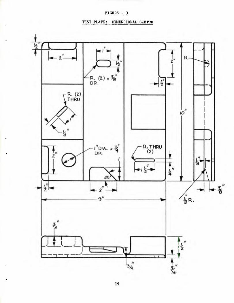
A test plate was designed with eight (8) areas representing typical weld repairs encountered in practice. This included various section thick- nesses (thin- 3/16", intermediate- 3/4" and thick- 1/2") and different constraints and sizes for each thickness. Figure 3 shows the dimensional details for the test plate. The test plate was mounted on a wood board pattern and the gating and risering system was affixed. Figure 4 shows the test plate with gates and risers attached.
HLH combiner housing casting was made using the dry sand pattern equipment consisting of 93 core boxes. Figures 5 and 6 show the cast- ing with gates and risers attached.
A. PHASE I; TEST BARS AND TEST PLATES
Melting and Pouring;
The metal was prepared from alloyed EZ33 or ZE41 ingots, foundry returns (gates, risers and scrap castings) and alloying elements (pure zinc, pure magnesium, rare earth as Mischaloy and zirconium as Zirmax), using standard melting and alloying procedure recommended by Magnesium Electron. (1) Various chemical compositions are shown in Table I. The following variables, which can have a major effect on chemical analysis, mechanical properties and internal and surface defects were closely controlled and maintained fairly constant for all ten melts.
1. Alloying temperature - 1450* F. 2. Time duration between alloying and pouring - 1 to 2 hours. 3. Zirconium grain refinement checked by fracturing one inch diameter
by twelve inches long fracture bars poured in cast iron mold. 4. Pouring temperature - 1500* F. 5. Pouring time - 8 to 9 seconds for test plates and 5 seconds for
test bars. 6. Pouring distance from the mold. 7. Time duration between pouring and shake out - 30 minutes.
The data was recorded on a record sheet for all ten melts. All molds were made using green sand with regular foundry additives for magnesium. An attempt was made to keep the chemical composition as close to the nominal as possible. Actual chemical analysis of all ten melts is shown in Table IV. Degree of grain refinement was checked, prior to pouring.

using one Inch diameter fracture bars. Zirconium was maintained at the same level for all ten melts to avoid large variation in grain size. Grain size is a major factor for mechanical properties of zirconium containing magnesium alloys. Contamination with elements such as iron, aluminum, etc., which are detrimental to zirconium grain refining was avoided. A typical photomicrograph of the polished section of a fracture bar is shown in Figure 7. The fracture bars from all ten melts had similar microstructure and grain size. A higher initial pouring temper- ature of 1500 F was used for test plates and test bars to account for the decrease in molten metal temperature because of heat losses that will occur in pouring thirty six (36) molds. (28 test bar molds plus 8 test plate molds.)
Separately cast test bars were grouped to minimize the effect of variables such as pouring temperature, mold material, etc. There were twenty eight (28) test bar molds in each melt, each mold having four test bars. These were divided into four groups of seven molds each. Groups were numbered 1, 2, 3 and 4, which indicates the order of pouring and hence a slight decrease in pouring temperature because of heat losses from the pot of molten metal while pouring. The following identification marking was used.
-9435-X-
Same for all— ' Melt number ^ Heat treat lot test bars and varies from number varies test plates. 1 to 10 for from 1 to 8 for
10 different 8 different heat melts. treatments.
On any melt X, 4-9435-X-Hl will consist of four test bars from groups 1, 2 and 3 described above. 4-9435-X-H2 will consist of four test bars from groups 4, 1 and 2 and so on. This will minimize the effect of variation in pouring temperature from mold 1 to 28. Thus, for any melt (X) heat treat (Y) combination, there were twelve test bars from three different molds as selected above. Two test bars from each of these three molds were used for welding as described in the next section, and the remaining six bars were not welded. This will minimize the effect of variation in molding sand and mold variables.
Eight test plates for each melt were numbered 1 to 8 in order of pour- ing. On any melt X, number 1 plate will be 4-9435-X-Hl, number 2 will be 4-0435-X-H2 and so on. Melt and heat treat numbers were steel stamped on test bars and test plates right after pouring to maintain tracability.
From each melt two standard spectrographlc discs were poured (one before pouring and one after pouring) and analysis was conducted per ASTM-E-2. The results were recorded and identified by melt number. Chemical analysis of actual melts poured is shown in Table IV.
Welding;
Test plates and half of the separately cast test bars were welded as follows.
Grooves were machined on all the separately cast test bars to maintain con-

slstency in size and location of the weld area. The grooves were machined on the cope side of all the test bars. Figure 8 is a sketch of the test bar used for welding.
On each test plate, eight areas were welded. Optimum preheat temperature, best welding procedure and the sequence of welding eight welds on each test plate were established by experimenting on preliminary test plates, prior to the welding of test plates on the test program.
Preheat temperature:
No preheat and preheat temperature of 400* F and 600 * F were tried. Weld quality was examined by zyglo and x-ray. Best results were obtained with 600* F preheat. Preheat time required to reach the temperature of 600* F in the thinnest section of the test plate was approximately thirty (30) minutes.
Through thickness weld:
The following were tried: No back-up material, mild-steel back-up and carbon back-up. Carbon back-up gave best results.
Sequence of welding:
The sequence of welding eight welds was determined on the basis of ease of welding a particular area (determined by thickness and location of the area for a given composition) and maintaining favorable heat flow to get enough temperature in the last area to be welded. Weld area identification numbers in Figure 19 also indicate the sequence of welding eight welds, weld number 1 being the first area welded, weld number 2 being the second area welded, and so on.
The same welding procedure, preheat time and temperature, and sequence of welding eight welds were maintained for all test plates. Weld areas for all the test plates were prepared by routing surface oxides using rotary cutters. Size of each weld was maintained reasonably constant from plate to plate. The test plates and test bars were vapor degreased prior to welding and were welded on the same day to prevent the surface from getting oxidized. All the weld areas were welded using extruded ZE41 weld rods w'th the following chemical composition: zinc - 4.20%, rare earth - 1.60%, zirconium - 0.52%. All the welded areas were cleaned and blended after welding.
Nondestructive Testing Of Weld Areas:
Welded areas of test plates were examined using fluorescent penetrant. Fluorescent penetrant inspection of the welded areas was also performed after heat treatment to Identify the effect of eight different heat treatments on all ten melts. After heat treatment test plates and test bars were examined radiographlcally per MIL-STD-453. Three separate ex- posures were made for three different thicknesses of each test plate. Test bars were x-rayed for reduced section only. Aii exposures were made using ZE41 penetrameters and the films were identified with identification marking explained before. Defects found in the weld areas of the test plates (see Figure 19 and Table VT) during radlographic inspection are

given In Table V.
Heat Treatments;
Time-temperatures for eight different heat treatments are given in Table II. Two step heat treatment (designated HI in Table II) is recommended by Magnesium Electron for ZE41 magnesium alloy. (1,2) Other heat treat- ments with longer time and higher temperature were examined to see the effect of prolonged heat treatments on tensile properties. They were also used to simulate repeated preheating and post heat treatment encountered during repeated welding. Steps were taken to ensure Identical temperature conditions for different heat treat loads. Time and temperatures were recorded on charts using an automatic recorder.
Mechanical Testing;
Separately cast test bars:
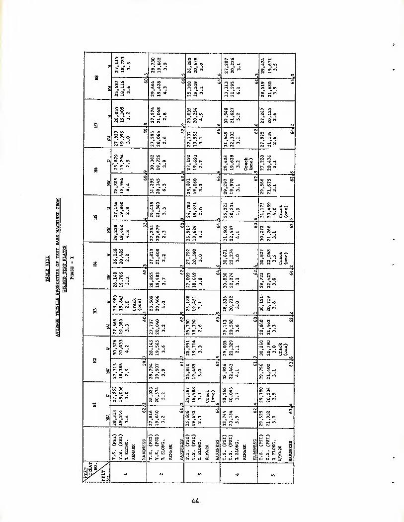
Five welded and five nonwelded test bars were tested for all eighty (80) melt-heat combination (10 melts x 8 heat treatments = 80). In all, 800 separately cast test bars were tested, which Included 400 welded and 400 nonwelded test bars. The testing was done for tensile, yield and elong- ation at room temperature per ASTM-E-8 using an automatic recorder on the tensile tester. One welded and one nonwelded test bar are being retained for further testing as necessary. The results for separately cast bars are shown in Table VII.
Test Plates:
Tensile testing was done on all ten melts, each melt consisting of eight test plates representing eight different heat treatments. Test bars were machined from- welded and nonwelded areas of test plates for all three thicknesses (thin - 3/16", intermediate - 3/4", and thick - 1 1/2") and tested for tensile, yield and elongation (see Figure 20 and Table IX). All the tensile specimens were flat, 1 inch gage length specimen dimensioned half size to F2 of method 211.1 of Federal Test Method Standard number 151. The location of the machined test bars from cast or welded surface was maintained constant for all test plates to minimize the variation in mechanical properties with distance from the cast or welded surface. The tensile testing was done at room temperature per ASIM-E-S using an automatic recorder on the test instrument.
Tensile properties for machined test bars from test plates are shown in Table VIII, along with Brinell hardness (500 kg load and 10 mm ball).
B. PHASE II; HLH COMBINER HOUSING CASTING
Data from the phase I of the program were analyzed to determine chemical composition and heat treatment for optimum combination of tensile pro- perties and weldability. The folowing chemical composition was selected: Zinc - 3.0 - 3.57,, Rare Earth - 1.8 - 2.27. and Zirconium - 0.7 - 0.9Z.
HLH Main Combiner Transmission Housing was poured and processed as shown in Figure 9.
Two different melting pots were used because of the large amount of metal
5

required. The average chemical composition of the two pots was: Zinc - 3.19% Rare Earth - 2.06% Zirconium - 0.72% Balance - Magnesium and Impurities.
The casting was poured at 1450* F. The weight of the casting with gates and risers was approximately 1,000 pounds.
After preliminary fluorescent penetrant Inspection, all the defects were removed and recorded. Radlographlc inspection did not reveal any addi- tional defect, except scattered areas of segreagation. The casting was cut into two halves and weld areas were cut out to have Identical loca- tions and sizes on both the halves. (See Figures 10 and 11 and Table XII) All areas were welded using extruded EZ33 weld rods because the chemical composition of the casting was closer to EZ33 alloy. The chemical composi- tion of EZ33weld rod was: Zinc - 2.20%, Rare Earth - 3.20%, and Zirconium - 0.56%. Extruded ZE41 weld rods were used In the Phase I of the program for welding of test plates on all ten (10) melts to get comparable data. A maximum preheat temperature of 600* F was used, wherever necessary. Sixteen (16) areas were welded on each section with welds varying in size and complexity. The casting was allowed to cool in air after welding. Weld areas were cleaned and dye checked. Small hair-line cracks were de- tected in two areas (one in each half) after preliminary dye check. Welds were examined radiographically and all welds were acceptable. Thus routing and rewelding of the same weld area was necessary. Two halves (designated section A and section B.) were heat treated as follows:
Section A: 625* F - 2 hours Air cool 340* F - 12 hours
Section B: 675* F - 2 hours Air cool 340* F - 12 hours
Heat treatment used for section A (designated Hi In Table II) is the one recommended by Magnesium Electron for ZE41 magnesium alloy (1,2). A higher temperature first step of 675* F was used for section B, which might relieve more residual stresses. Section A was retained to observe any delayed cracking, because it was more likely to exhibit delayed cracking than section B. Section B was used for evaluation of tensile properties.
After heat treatment both halves were inspected visually and with fluorescent penetrant, and all weld areas were found to be satisfactory.
Test bar locations for evaluation of tensile properties were marked on section B (See Figures 12 to 15 and Table XIII). Test locations were selected as follows:
1. Thin, thick and average nonwelded areas. 2. Thin, thick and average welded areas. 3. Areas with segregation detected in x-ray.
Section thickness and riser/chill/neutral location of each test bar were recorded and is shown in Table X, along with tensile properties, (tensile strength, yield strength and % elongation) and Brinell hardness at each location. Tensile testing was done at room temperature per ASDl- E-8, using an automatic recorder on the test instrument.
r~
Section A, which was retained to observe any delayed cracking did not reveal any cracking in the weld areas during visual and fluorescent penetrant inspection after thirty days.

III. DISCUSSION OF RESULTS
PHASE I OF THE PROGRAM:
Data from the Phase I of the program were used to determine chemical composition and heat treatment which give optimum combination of weldability and tensile properties. Weldability was determined from the following:
1. Tensile properties of welded bars - both separately cast and machined from test plates.
2, Defects in welded areas of test plates detected during non- destructive testing. (Fluorescent penetrant and x-ray radio- graphy.)
For a given section size, tensile properties of magnesium alloys con- taining zirconium as a grain refiner, depend mainly on the grain size and also on alloy content, heat treatment and presence of discontinuities, (oxides etc). (1) Grain size is mainly determined by soluble zirconium content, which can be checked by visual observation of grain structure of one inch diameter fracture bar. (1) Grain size was maintained reason- ably constant for ten different chemical compositions for the Phase I of the program. Thus the variation in tensile properties will be due to variations in chemical composition, heat treatment and random discon- tinuities.
As stated before ten different chemical compositions were selected with varying zinc and rare earth contents and each chemical composition was given eight different heat treatments.
Zinc and rare earth are the major alloying elements for EZ33, ZE41 and intermediate zinc-rare earth type magnesium alloys. Zinc increases tensile strength and yield strength slightly, and reduces elongation. (1) Rare earth metals reduce microporosity and hot tearing tendency and make the alloys weldable. (1) Rare earth metals also reduce tensile strength and elongation. (1) Thus zinc improves the strength values while rare earth reduces tensile properties but improves castability and weldability. Thus by varying zinc and rare earth contents, tensile properties, castability and weldability can be varied significantly. The chemical compositions selected in the phase I of the program will exhibit different levels of tensile properties, castability and weld- ability. In Table I, chemical compositions 4, 5, 6, 7, 8 and 9 are within ZE41 specification, while 1, 2, 3 and 10 are from the gap be- tween EZ33 and ZE41. Chemical composition 10 has higher rare earth than allowed by AMS 4439 specification for ZE41 alloy.
Tensile Properties:
Separately cast test bars: Table VII (nonwelded bars):
In general, ZE41 alloy (chemical compositions 4, 5, 6, 7, 8 and 9) shows higher tensile properties (Approximately 127o higher T.S., 15% higher Y.S. and higher elongation) as compared to alloys from across the gap between EZ33 and ZE41 (chemical compositions 1, 2, 3).
Within the ZE41 range, at the same zinc level, tensile properties decrease

slightly with the increase in rare earth content, as expected. Chemical composition number 2 shows the best, and chemical composition, number 3, the worst tensile properties from melt numbers 1, 2, 3 and 10. (Which are outside ZE41 range).
Machined test bars from test plates: Table VIII (nonwelded bars):
Tensile properties of nonwelded machined test bars from test plates show a trend similar to separately cast bars. Again the tensile properties of ZE41 alloys are higher than the alloys taken from the gap between EZ33 and ZE41 (melt numbers 1, 2, 3 and 10). Chemical composi- tion number 2 shows the best and number 3 the worst tensil properties from melt numbers 1, 2, 3 and 10 (which are outside ZE41 range). Within ZE41 range at the same zinc level, tensile properties decrease slightly with the increase in rare earth content, as expected.
Weldability:
1. Tensile Properties:
Separately cast test bars: Table VII (welded bars):
Withing ZE41 range melt numbers 4 (low zinc and low rare earth) and 5 (low zinc and high rare earth) have the best tensile properties. Melt numbers 6, 7, 8 and 9 have slightly lower tensile strength, similar yield strength and much lower elongation as compared to melt numbers 4 and 5.
Outside ZE41 range, melt number 2 shows the best tensile properties. In general, welded test bars have lower tensile strength and elongation and similar yield strength as compared to nonwelded bars.
Machined test bars from welded test plates: Table VIII (welded bars):
Tensile strength and yield strength of welded test bars are very similar to nonwelded test bars, while % elongation shows a big scatter. At the same zinc level more cracking is observed in alloys with low rare earth content as compared to alloys with high rare earth content. Yield strength of welded test bars is less sensitive to changes in chemical composition than tensile strength and elongation.
Chemical compositions numbers 2 and 5 show consistently high properties for welded test bars and the tensile strength, yield strength and elongation are very similar to nonwelded test bars.
2. Nondestructive Testing:
Fluorescent penetrant inspection and x-ray radiography were used to detect and identify defects (mainly cracks) in the welded areas of test plates. Cracking in the welded areas was the major problem on pre- production HLH combiner housing castings.
Table V summarizes the defects found in the welded areas of test plates.
In general, as would be expected, chemical compositions number 1, 2, 3

(which are from across the gap between EZJ^3 and ZE41) exhibit less cracking in welded areas as compared to ZE41 alloy (chemical composi- tion numbers 4, 5, 6, 7, 8 and 9). This is because chemical composi- tion numbers 1, 2 and 3 have lower zinc and higher rare earth as compared to ZE41 alloy, and rare earth improves the weldability in these alloys. Within ZE41 range chemical composition number 5 (low zinc and high rare earth within ZE41 specification) gives best weld- ability, as would be expected. At the same zinc level, weld cracking decreases with increase in rare earth content - compare chemical com- positions number 4 and 5, 6 and 7, and 8 and 9. Chemical composition number 2 shows the least tendency for weld cracking.
Optimum Combination Of Weldability And Tensile Properties:
As stated before one of the objectives of the program was to resolve the weld cracking problem on HLH combiner housing casting by varying the chemical composition. As explained before this has to be done at the expense of tensile properties. As discussed in the previous section, chemical composition number 2 showed least tendency for weld cracking from all the chemical compositions selected, while chemical composition number 5 showed least tendency for weld cracking within ZE41 range.
Comparison of tensile properties of chemical compositions number 2 and 5, shows that chemical composition number 2 has approximately lOZ lower tensile strength, 12% lower yield strength and 107, lower elonga- tion, for nonwelded separately cast test bars. On nonwelded test bars machined from test plates, chemical composition number 2 shows 3% lower tensile strength, 8% lower yield strength and 187, higher elongation as compared to chemical composition number 5. Thus, chemical composition number 2 exhibits much better weldability (Table V) and slightly lower tensile properties as compared to the optimum chemical composition number 5 within ZE41 range. Hence it was decided to use chemical composition number 2 on HLH combiner housing casting for the phase II of the program:
Zinc - 3.0 - 3.57, Rare Earth - 1.8 - 2.27, Zirconium - 0.7 - 0.97, Balance - magnesium and impurities
The effect of variation in chemical composition (zinc and rare earths) on tensile properties and weldability for zinc-rare earth zirconium tjrpe magnesium alloys is schematically shown in Figure 16.
Various heat treatments listed in Table II included a heat treatment (designated Hi) recommended for ZE41 alloy by Magnesium Electron Company (1) Other heat treatments were selected to see the effect on tensile pro- perties of prolonged heat treatments as would be encountered in repeated preheating and post heat treating during repeated welding. It is clear that various heat treatments give similar tensile properties, and prolonged exposure at 625* F up to twenty (20) hours and at 675* F up to twelve (12) hours, does not appreciably affect the tensile properties. Within the limits of time and temperatures for various heat treatments it appears that the precipitation hardening process for this type of magnesium alloys is not very sensitive to changes in heat treatment.
10

,' ft..', ■■■-^^^■i ^ a.
B. PHASE II OF THE PROGRAM:
Phase II of the program used the data from the Phase I of the program for the pouring and the processing of HLH combiner housing casting. Excellent weldability of the chemical composition number 2 was estab- lished by successful welding of thirty two (32) areas (16 each on each of the two halves) of various complexities - various section thicknesses and various thickness constraints surrounding the weld area. All the welded areas were acceptable per fluorescent penetrant inspection and x-ray radiography, and rewelding of the same area was not necessary. Machined test bars were taken from various section thicknesses and various locations (chill/riser/neutral). In general, tensile proper- ties of the machined test bars from HLH combiner housing are lower than cut test bars from test plates (chemical composition number 2) because of the much larger size of the casting as compared to the test plate (poured weight: HLH combiner housing - 1,000 pounds, test plate - 10 pounds). Tensile properties of machined test bars from HLH combiner housing reveals the following: (See Table X)
1. Tensile properties of test bars taken from different thicknesses and different locations (chill/riser/neutral) are comparable (test bar number 1 through 11, 16 through 20, 23). This means that for sand castings, faster solidification through the use of chills may not improve the tensile properties appreciably (test bar number 35 through 39).
2. Segregation detected in x-ray radiography does not affect the tensile properties significantly as shown by the results on test bar number 21 and 22 (See Table X) . These test bars had number 3 segregation based on ASlM-E-155 - reference radiographs for inspection of alumi- num and magnesium castings.
3. Tensile properties of test bars cut from welded areas are very similar to nonwelded test bars. (Test bar number 24 through 34). This points to the excellent weldability of the recommended chemical composition.
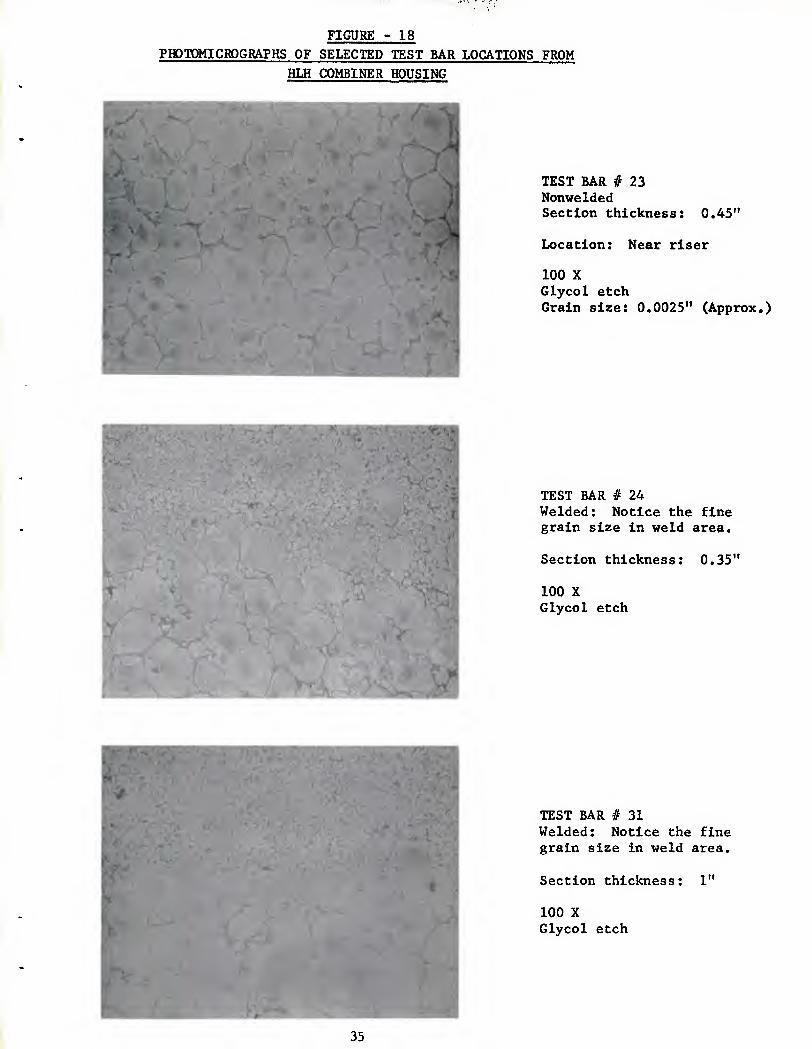
Photomicrographs of some selected test bars machined from HLH combiner housing are given in Figures 17 and 18. Notice the diff-^rence in grain size because of the following factors.
(a) Section thickness: Test bar taken from thin section has finer grain size as compared to test bar taken from thick section.
(b) Location: Test bar taken from chilled section has slightly finer grain size as compared to test bar taken from risered section.
Difference in grain size accounts for the slight difference in tensile properties of different nonwelded test bars in Table X. Extremely fine grain size in the weld area results from the extremely fast solidification rate (instantaneous solidification) of the small mass of molten metal in the weld area.
11

C. GENERAL DISCUSSION
The following discussion although not directly related to the objective of this program can be helpful to casting designers, quality control personnel and for future review of AMS and other specifications. Most of the comments are based on the results obtained in Phase I and Phase II of the program.
1. Tensile properties of test bars taken from various section thicknesses of the test plates vary slightly, the tensile strength and elongation being affected more than yield strength. However, the tensile pro- perties do not appear to decrease as much with the increase in section thickness, as found in other casting alloys. This is because of the fact that in this type of magnesium alloys, zirconium grain refining is a major determinant of tensile properties. The grain size will be mainly established at the melting stage by the amount of soluble zirconium in the alloy, and will vary only slightly with different solidification rates encountered in different section thicknesses.
2. Room temperature tensile properties are not very sensitive to various heat treatments selected for this program. It appears that for the temperatures investigated, time at which tensile properties might start to decrease was not reached by the selected heat treatments. Tensile properties are stable up to twenty (20) hours at 625* F and up to twelve (12) hours at 675* F.
3. For a given chemical composition, hardness is not very sensitive to different heat treatment times and temperatures, and varies only slightly with chemical compositions. As can be seen from Table VIII, hardness specified for ZE41 alloy by AMS 4439, (Brinell 65 to 80 using 500 kg load), is on the high side. Hardness varies from Brinell 60 to 69, for different heat treatments and chemical compositions for ZE41 alloy.
4. Within ZE41 range, low zinc and high rare earth gives the best weld- ability. It may be necessary to control the composition near low zinc and high rare earth for expensive castings that must be salvaged by welding. Low zinc and high rare earth range of ZE41 alloy gives the lowest tensile properties obtainable from ZE41 alloy, and the tensile property requirements for both separately cast and machined test bars per AMS 4439 specification may not be met.
5. Tensile properties of machined test bars taken from chill, riser or neutral areas of the HLH combiner housing are comparable. Thus, the tensile properties cannot be changed significantly by chilling (see Table X).
6. There does not appear to be any direct correlation between tensile properties and Brinell hardness (see Table X).
7. The tensile properties of test bars cut from ZE41-type castings will vary with the size and the geometry of the castings, as with all casting alloys. The tensile properties of test bars machined from HLH combiner housing (Table X) are lower than those machined from test plates. (Table VIII, Melt number 2).
12

8. Test bars machined from areas containing flow-line type of segregation detected in x-ray radiography show properties similar to test bars machined from sound areas of test plates (see Table XI).
9. Some of the separately cast and machined test bars had oxide inclu- sions in the fractured surface. It appears that small oxide inclu- sions do not have any detrimental effect on tensile properties. On the other hand, large oxide inclusions will reduce the tensile strength and elongation. In general, magnesium alloys are prone to oxidation during melting and pouring.
10. Welding: Thin areas are more prone to cracking in welding than thick areas. Thin area constrained by heavy sections on both sides is most difficult to weld followed by thin area with heavy section on one and medium section on the other side, followed by thin section on the edge of the casting. For the test plate used in this program weld area number 1 and 2 were most prone to cracking. (See Figure 19).
11. Two step heat treatment (625* F for two (2) hours, air cool, 340* F for twelve (12) hours) provides effective stress relief in ZE41- type castings. Low temperature heat treatment of 480* F for twenty- four (24) hours was not examined in this program, which may give acceptable mechanical properties but could result in less effective stress relief.
12. The creep properties of the alloy selected for pouring of the HLH combiner housing (taken from the gap between EZ33 and ZE41), were not investigated, but they might be better than ZE41 alloy because of higher rare earth content. The creep properties of the selected alloy may be inferior to EZ33 alloy because of lower rare earth content. Rare earth component is responsible for creep properties in this type of magnesium alloys.
13

IV. CONCLUSIONS
1. It was verified in this program that the tendency towards weld cracking increases with an increase in zinc content and a decrease in rare earth content in ZE41-type magnesium alloys.
2. Zinc increases the tensile strength and yield strength, and reduces elongation for a given rare earth content, while the rare earth com- ponent improves the weldability but reduces tensile properties.
3. Within ZE41 range, low zinc and high rare earth content had the best weldability but the lowest tensile properties.
4. One chemical composition taken from the gap between ZE41 and EZ33 magnesium alloys exhibited the best weldability from ten (10) dif- ferent chemical compositions selected for this program. This alloy (the selected alloy) had better weldability but lower tensile pro- perties than low zinc, high rare earth range of ZE41 alloy.
5. The tensile properties of the selected alloy and other chemical com- positions, resulting from various heat treatments, examined in this program were similar. Deterioration of tensile properties with pro- longed heat treatments was not observed up to twenty (20) hours at 625* F and twelve (12) hours at 675* F. This stability of properties indicate that ZE41-type castings can withstand several preheating, welding, and post heat treating cycles without deteriorating the tensile properties.
6. Sixteen areas of different complexities were welded on each half of the HLH combiner housing casting without any weld cracking. (Chemical composition of the casting: zinc - 3.197,, rare earth - 2.06% and zirconium - 0.72%). All the weld areas were acceptable per fluores- cent penetrant and x-ray radiographic inspection.
7. Average tensile properties of test bars machined from the welded areas of the HLH combiner housing were similar to nonwelded areas.
8. The tensile properties of the selected alloy, taken from various section thicknesses and chill/riser/neutral locations of the HLH combiner housing, were very similar. Thus, for sand castings, in- creasing the rate of solidification by chilling may not improve the tensile properties significantly.
9. Brinell hardness of the selected alloy ranged from 50 to 60 (500 kg load and 10 mm ball).
10. High temperature heat treatment (Two step process: 625* F or 675* F for two (2) hours, air cool, 340* F for twelve (12) hours) provides effective stress relief in the selected alloy.
11. For large, complicated magnesium castings, such as the HLH combiner housing, the cracking in the weld areas during welding as well as delayed cracking in the weld areas can be overcome by proper selection of chemical composition and heat treatment.
14

V. RECOMMENDATIONS
1. For large complicated magnesium castings, such as the HLH combiner housing, a chemical composition from across the gap between EZ33 and ZE41 magnesium alloys will be more suitable, because it is less prone to weld cracking as compared to ZE41 magnesium alloy. The following chemical composition is recommended.
Min. Max. Zinc 3.0 - 3.5
Cerium (Total Flare Earths) 1.8 - 2.2
Zirconium (Total) 0.6 - 1.0
Zirconium, Soluble 0.4
Manganese - - 0.15
Copper - - 0.10
Nickel - - 0.01
Other Impurities (Total) - - 0.30
Magnesium - - Remainder
The tensile properties of this alloy are lower than ZE41 alloy. The alloy can be welded with EZ33 rods, using a preheat temperature of 600* F, when necessary. Two step heat treatment (625* F for two (2) hours, air cool, 340* F for twelve (12) hours) provides adequate stress relief in this alloy.
This recommendation is based on static tensile properties and weldability. It should be emphasized that the above alloy is recommended for large, complex magnesium castings, where excellent weldability is a major con- sideration. For most magnesium castings currently designed by the heli- copter and aerospace industry, low zinc and high rare earth range of ZE41 alloy gives the best combination of tensile properties and weld- ability.
2. Issue a new specification for this alloy or study EZ33 and ZE41 alloy specifications to see if the recommended alloy can be incorporated in the specification.
3. Investigate creep and fatigue properties of the recommended alloy.
15

VI. REFERENCES
1. MEL Foundry Instructions, USNH 73, "The preparation of magnesium - zirconium alloys for sand castings", published by Magnesium Electron LTD, London, England.
2. E. F. Emley, Principles of Magnesium Technology, Pergamon Press, 1966.
16

FIGURE
SCHEMAnC REPRESENTATION OF ALLOY RANGES
5 '
CO
^ 3 .
H O H
M P4
MELT # 10
ZE4I ALLOY
(MELT #4 THRU 9)
PERCENT ZINC
17

FIGURE - 2
MULTIPLE TEST BARS WITH GATES AND RISERS ATTACHED
18
r ..,,-j,. „.,,.,- ..-.5., ^jj
FIGURE - 3
TEST PLATE; DIMENSIONAL SKETCH
19
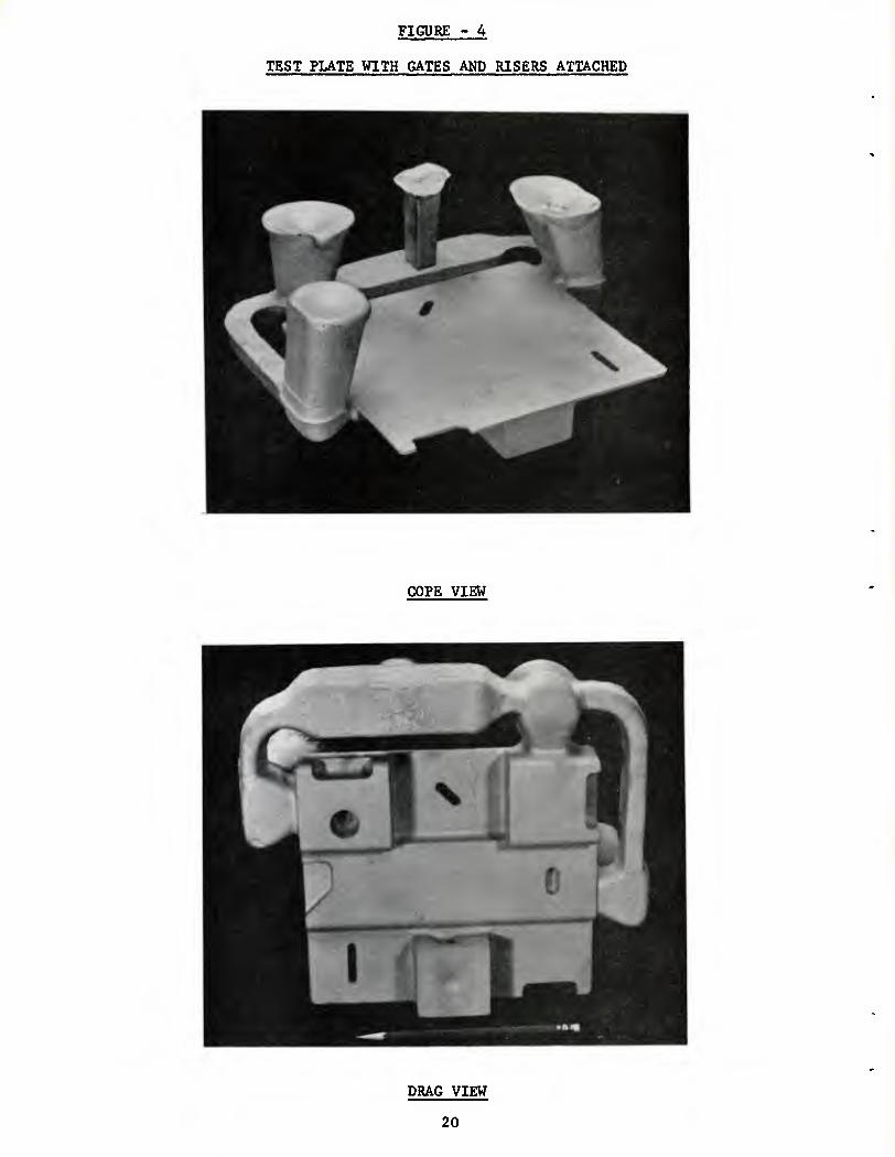
FIGURE - 4
TEST PLATE WITH GATES AND RISERS ATTACHED
COPE VIEW
DRAG VIEW
20
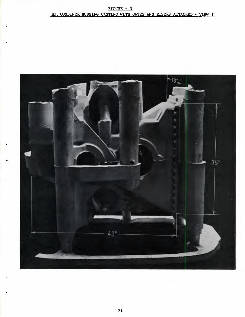
FIGURE - 5 HLH COMBINER HOUSING CASTING WITH GATES AND RISERS ATTACHED - VIEW 1
21
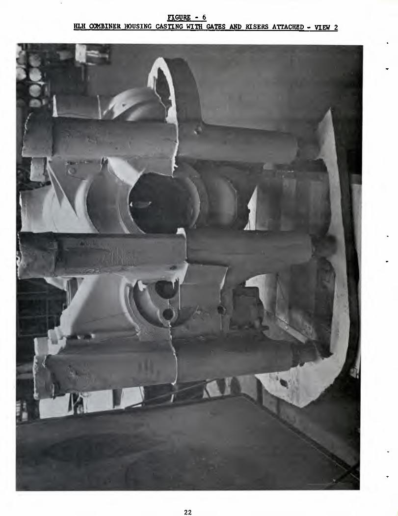
FIGURE - 6 HLH aMBINER HOUSING CASHNG WITH GATES AND RISERS ATTACHED ■. VIEW 2
22
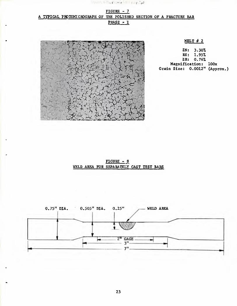
FIGURE - 7 A TYPICAL PHOTOMICROGRAPH OF THE POLISHED SECTION OF A FRACTURE BAR
PHASE - I
MELT # 2
ZN: 3.30% RE: 1.95% ZR: 0.76%
Magnification: lOOx Grain Size: 0.0012" (Approx.)
FIGURE - 8 WELD AREA FOR SEPARATELY CAST TEST BARS
0.75" DIA. 0.505" DIA. 0.25" WELD AREA
23

(Reject)
(Hgjgy^:)
FIGURE - 9
PROCESSING OF HLH COMBINER HOUSING
Core Making and Assembly
? He 1ting
f Pouring
? Sandblast
f Sawing: Gates and Risers
f Benching
f Acid Clean
f Pickle (Dow 1)
f Zyglo
? X-ray
f Saw Casting in Two Halves
? Preparation of Weld Areas
f Welding
? (Preheat temperature: 600* F,
when necessary)
Clean and Dye Check Weld Areas (Accept) f
X-ray Welds ■ (Accept)
Heat Treatment
? Sandblast
? Pickle (Dow 1)
? Zyglo
f Tensile Testing (Cut Bars)
24

TABLE - XII
SUMMARY TABLE OF WELD AREAS ON TWO HALVES OF HLH COMBINER HOUSING
The following is sunmary table for the weld areas for the HLH combin-
er housing. All the defects were cut out from both the sections
and similar areas were cut out to have Identical weld areas on
both halves. The type of defect found in visual and fluorescent
Inspection is also given in the table. Typical weld areas are
shown In the following photographs.
Weld Number
Size of The Weld:Length (inch) X Width (inch) X Depth (inch)
Section A Section B
1 2x1x1 .•«.. Shrinkage
2 1.5 X 1.5 X 1.5 _-- Shrinkage
3 0.5 X 0.5 X 0.25 Shrinkage ...
4 1 X 0.5 X 0.1 Shrinkage ...
5 2" X 0.4 X Thru wall Shrink crack ...
6 2 X 1 X 0.25 Shrink crack ...
7 1.25 X 1.25 X 1 Shrinkage ...
8 1 X 0.75 X 0.2 _-- Shrinkage
9 1 X 0.7 X 0.5 _•• Dirt hole
10 3.5 X 1.25 X 0.25 M»» Shrinkage
11 1 X 0.5 X Thru wall _-_ Crack
12 4 X 0.5 X 0.25 — MM Shrink crack
13 3 X 1.25 X 0.25 Shrinkage ...
14 1 X 0.5 X 0.3 ... Dirt hole
15 0.7 X 0.5 X 0.4 ... Shrinkage
16 0.5 X 0.5 X 0.2 ... Dirt hole
25
FIGURE - 10
TYPICAL WELD AREAS ON TWO HALVES OF HLH COMBINER HOUSING
VIEW - 1
VIEW - 2
26

FIGURE - 11
TYPICAL WELD AREAS ON TWO HALVES OF HLH COMBINER HOUSING
VIEW
VIEW
27

TABLE XIII
SUMMARY OF MACHINED TEST BAR LOCATIONS FOR HLH COMBINER HOUSING
The following photographs are numbered. Refer to the following
table to identify test bar locations.
View #
Test Bar Numbers
1 1. 2, 3. 5, 7. 11. 17, 21, 24, 25
2 6, 8. 10, 16. 30, 31
3 4. 9, 11, 17, 22, 23, 26, 29, 33
4 18, 19, 32. 34
5 20
6 27. 28
7 35. 36, 37. 38. 39
Refer to Table X for section thickness, chill/riser/neutral locations,
tensile properties and other details.
28
evj
O s
O
W CO
s U
8
g
O
6
z o M H CJ M CO
< H CO
M
s
CM
g ^
29
CO
M OS
g CO
O
PQ
iZi O w H O H CQ
H CO
g CO
I
51
30

FIGURE - 14 MACHINED TEST BAR LOCATIONS FOR HLH COMBINER HOUSING
SECTION B
VIEW - 5
VIEW - 6
31
FIGURE - 15 MACHINED TEST BAR LOCATIONS FOR HLH COMBINER HOUSING
SECTION B
np mmmji^mi^^
/J^JM W^^ Ifl
4 Mi 1 s^l^B^B
Hp f^ ^H^ ^B mmgy- m
^^^^^^^HJ^^^HHv ^^^^^H
VIEW - 7
NOTE: These test bars were taken from similar locations on section B of the casting.
32

FIGURE - 16
SCHEMATIC REPRESENTATION OF THE EFFECT OF
VARIATION IN CHEMICAL COMPOSITION ON
TENSILE PROPERTIES AND WELDABILITY
FOR ZINC-RARE EARTH-ZIRCONIUM TYPE
MAGNESIUM ALLOYS
LOWEST MECHANICAL PROPERTIES BEST WELDABILITY
CO
8
H P4
RECOMMENDED ALLOY
INTEBMEDIATE MECHANICAL PROPERTIES
GOOD WELDABILITY
HIGHEST MECHANICAL PROPERTIES
POOR WELDABILITY
3.0 4.0
PERCENT ZINC
Low zinc and high rare earth chemical composition within ZE41 range also has good weldability, which is adequate for most castings of current design. The recommended alloy (recommended for large complex castings with intricate de- sign) has better weldability and slightly lower tensile properties. Good weldability Implies that the alloy is less prone to weld cracking.
33

FIGURE - 17 PHOTOMICROGRAPHS OF SELECTED TEST BAR LOCATIONS FROM
HLH COMBINER HOUSING
APPENDAGE # 2 Nonwelded Section thickness: 0.5" Chilled
Location: Intermediate between riser and chill
100 X Glycol etch Grain size: 0.0025" (Approx.)
TEST BAR # 6 Nonwelded Section thickness: 0.40"
Location: Neutral
100 X Glycol etch Grain size: 0.0020" (Approx.)
TEST BAR # 9 Nonwelded Section thickness: 2.75"
Location: Riser
100 X Glycol etch Grain size: 0.0033" (Approx.)
34
' ■- i-'^nM"i't,-T'''5r'>-^
FIGURE "IS PHOTOMICROGRAPHS OF SELECTED TEST BAR LOCATIONS FROM
HLH COMBINER HOUSING
TEST BAR #23 Nonwelded Section thickness: 0.45"
Location: Near riser
100 X Glycol etch Grain size: 0.0025" (Approx.)
TEST BAR # 24 Welded: Notice the fine grain size in weld area.
Section thickness: 0.35"
100 X Glycol etch
TEST BAR # 31 Welded: Notice the fine grain size in weld area.
Section thickness: 1"
100 X Glycol etch
35

TABLE I
SELECTED CHEMICAL COMPOSITIONS
MELT HOy CHEMICAL COMPOSITBN NUMBER
ZINC Mln Max
RARE EARTH Min Max
ZIRCONIUM TOTAL
Mln Max MN. Max
CU. Max
NI. Max
IMPURITIES TOTAL
Max
4-9435-1 3.0 - 3.5 1.5 - 1.9 0.7 - 0.9 0.15 O.IO .01 0.30
4-9435-2 3.0 - 3.5 1.8 - 2.2 0.7 - 0.9 0.15 0.10 .01 0.30
4-9435-3 3.0 - 3.5 2.1 - 2.5 0.7 - 0.9 0.15 0.10 .01 0.30
4-9435-4 3.5 - 4.0 0.75 - 1.25 0.7 - 0.9 0.15 0.10 .01 0.30
4-9435-5 3.5 - 4.0 1.25 - 1.750 0.7 - 0.9 0.15 0.10 .01 0.30
4-9435-6 4.0 - 4.5 0.75 - 1.25 0.7 - 0.9 0.15 0.10 .01 0.30
4-9435-7 4.0 - 4.5 1.25 - 1.750 0.7 - 0.9 0.15 0.10 .01 0.30
4-9435-8 4.5 - 5.0 0.75 - 1.25 0.7 - 0.9 0.15 0.10 .01 0.30
4-9435-9 4.5 - 5.0 1.25 - 1.750 0.7 - 0.9 0.15 0.10 .01 0.30
4-9435-10 4.25- 4.75 1.8 - 2.0 0.7 - 0.9 0.15 0.10 .01 0.30
NOMINAL COMPOSITION
MELT NUMBER ZINC RARE EARTH ZR.
4-9435- 4-9435- 4-9435- 4-9435- 4-9435- 4-9435- 4-9435- 4-9435- 4-9435- 4-9435-
1 2 3 4 5 6 7 8 9 10
3.25 3.25 3.25 3.75 3.75 4.25 4.25 4.75 4.75 4.5
1.70 2.00 2.30 1.0 1.5 1.0 1.5 1.0 1.5 2.0
0.8 0.8 0.8 0.8 0.8 0.8 0.8 0.8 0.8 0.8
NOTES: (1) Maintain pouring temperature for test bars and test casting to within ± 50" F. (2) Four as close to the mold as possible. (3) Four two discs before and after pouring. Leave some melt at the bottom. (4) Check Zr. grain refinement using fracture bars.
36

TABLE II
SELECTED HEAT TREATMENTS
IDENnFICATION TEMP CF) TIME (Hrs.) TEMP TIME
HI 625 2 Alrcool 340 12
H2 625 4 Alrcool
H3 625 8 Aircool —_
84 625 12 Aircool 340 12
H5 625 20 Aircool —
H6 675 2 Aircool 340 12
H7 675 8 Aircool _>_
H8 675 12 Aircool _-_
TABLE III
AMS 4439 SPECIFICATION REQUIREMENTS FOR ZE41 ALLOY Chemical Composition
Min. Max. Zinc 3.5 - 5.0 Cerium (Total Rare Earths) 0.75 - 1.75 Zirconium, total 0.40 - 1.0 Zirconium, soluble (1) 0.40 - Manganese (1) — - 0.15 Copper (1) — - 0.10 Nickel (1) — - 0.01 Other impurities, total — - 0.30 Magnesium Remainder
(1) Determination not required for routine acceptance.
Tensile Properties
PROPERTY CAST TENSILE SPECIMENS SPECIMENS CUT
Average
FROM CASTINGS
Minimum
Tensile strength, PSI 29,000 28,000 26,000
Yield strength at 0.2 % offset, PSI 19,500 19,500 17,500
Elongation, % in 2 inch 2.5 2.5 2.0
37
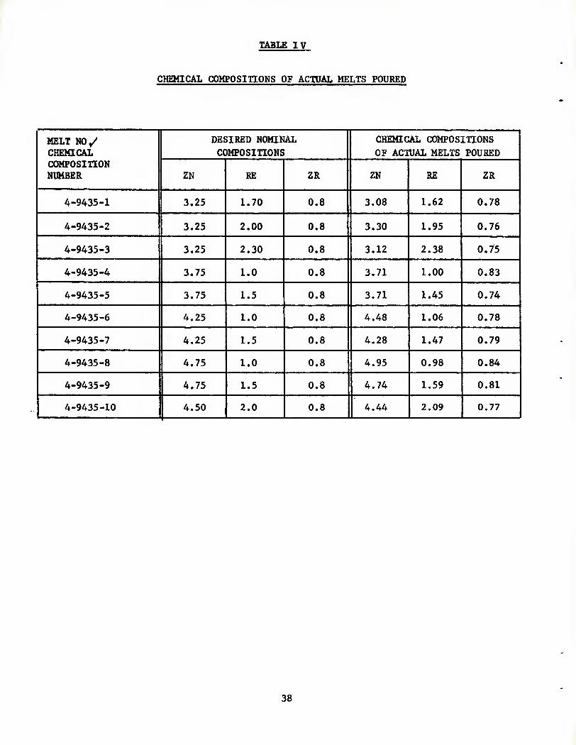
TABLE IV
CHEMICAL COMPOSinONS OF ACTUAL MELTS POURED
MELT NO/ CHEMICAL COMPOSITION NUMBER
DESIRED NCMtNAL COMPOSITIONS
CHEMICAL COMPOSITIONS OF ACTUAL MELTS POURED
ZN RE ZR ZN RE ZR
4-9435-1 3.25 1.70 0.8 3.08 1.62 0.78
4-9435-2 3.25 2.00 0.8 3.30 1.95 0.76
4-9435-3 3.25 2.30 0.8 3.12 2.38 0.75
4-9435-4 3.75 1.0 0.8 3.71 1.00 0.83
4-9435-5 3.75 1.5 0.8 3.71 1.45 0.74
4-9435-6 4.25 1.0 0.8 4.48 1.06 0.78
4-9435-7 4.25 1.5 0.8 4.28 1.47 0.79
4-9435-8 4.75 1.0 0.8 4.95 0.98 0.84
4-9435-9 4.75 1.5 0.8 4.74 1.59 0.81
4-9435-10 4.50 2.0 0.8 4.44 2.09 0.77
38

TABLE V
DEFECTS IN WELDED AREAS OF TEST PLATES - X-RAY
RADIOGRAPHIC INSPECTION
PHASE - I
1 ■
\WELD XAREA
MELTX No. \
1 2 3 4 5 6 7 8
1 3-C 2-D
6-C 2-D
3-C 1-C 3-D
2 1-C 4-D
5-C 3-D
1-D
3 4-C 3-D
4-C 3-D
1-D 1-D
4 5-C 7-C 5-C 5-C
5 5-C 8-C 3-C
6 7-C 7-C 4-C 7-C
7 S-D 5-C
2-D 2-C 3-C
2-D
8 8-C 8-C 6-C 7-C
9 4-C 8-C 1-C 6-C
10 3-C 1-D
6-C 2-C 8-C
NOTES: (1) See Figure 19, and Table VI for the explanation of weld areas of test plates. (1 through 8)
(2) Defect code: C: crack, D: dross (Foreign material, less dense.) Cracks vary in size. Dross appears as a single particle.
(3) Each melt has eight test plates. The above table indicates the total number of defects, (sum of the defects on eight test plates) in each of the eight weld areas for each melt.
(4) All the test plates had flow line type of eutectic segregation in weld area number 8, which resulted from multiple passes used for welding this thin area on the edge of the test plate. This defect does not have any detrimental effect on tensile properties. (See text for details.)
39

FIGURE - 19 IDENnFICATION OF WELD AREAS OF TEST PLATE FOR
TABLE V
I ' J
^
cr
'
)
)
^
\ V
V
40

TABLE VI
EXPLANATION OF WELD AREAS OF TEST PLATE FOR
TABLE V
WELD AREA #
EXPLANATION
1 Thru the thickness weld in thin section: Heavy section on one side
2 Thru the thickness weld in thin section: Heavy sections on both sides
3 Intermediate section: Weld on the edge
4 Thick section
5 Thick section: Weld on the edge
6 Thick section: Weld on the edge
7 Intermediate section
8 Thru the thickness weld in thin section: Weld on the edge
Section
Thin Intermediate Thick
Thickness
3/16" 3/4" 1 1/2"
As can be seen from Table V, thin sections constrained by nearby
heavy sections (weld number 1 & 2) are most prone to weld cracking and
hence most difficult to weld. Tendency towards weld cracking increases
with increasing zinc and decreasing rare earth content (that is
increasing zinc/rare earth ratio).
41

r
s »<
o fS (Ti en 3 en o lA o <t n •* o% CO o <t lA lA CM {» o C\ O O 00 <M 00 VO o 00 ON •-I vO en **
r^ <r> n •^o 0^ eM -* CO CM <7N 1-4 cn 00 CM CM
a <N rH es »H CN CN CM rl CM
O CM \o lO 3 r-^ en o tA a CO CM o en CM 00 cn *A £ 00 a* -* »o CM r*. CM t-l <^ ^ o CO »4 O CM
r-H. <^ en r>- o* en u-t <T> >-i o (M tn ^ cn -* CM <-i CM es eN ■-M CO CM tn C-4
<* o* 3 !>. 00 O cn VO r^, ■-* o en oo cn en cn CM ON
3 ■J- c^ 00 cn -* cn O^ "* o -4- 1-4 lA o -* CM
\0 <7» CM f** o cn <T e» CM (7^ CM CM o CM cn (N w CM CM CM CM CM tn CM
r^ X
>H •* cn •^ CM MD lA CM 00 cn <N r*. <*■ ^ •<»■ r* lA 00 o lA S .-1 *rt *» m 00 CM ■<r en eM I-* CM O 00 r^ VO
r^ o\ fO 00 o cn en 00 CM eN (M lA o CM en M fW CM CM CM rH en CM cn CM
<t o O cn O VO lA 1-4 »A r- ^ 00 r^ n r^ <t f-i r>. <t CM » ^ 00 r^ O} 00 r-4 m VO lA 1-1 cn <r 5 o o io 00 M r-* 00 <f en r* CM O en CM Ov CM cn CJ ■-4 CM r-l CN< 1-4 CO CM (M CM
^o X
n a -* rj ON VO lA o\ 00 CO tNJ lO CM ■^ sr en m vO o
3 <M f*. rv ^t^ »n 00 vO en r- •-4 cn CO ON fH lA
•^ r*. oo' en CO o* cn >J 00 CM CM cn <n o en CO CM l-l <M CM CM iH en CM cn CM
^0 o ON vO r^ P-* CM CM lA lA ON Cft 00 a^ eM vO ON o o r^
» o ON .-* o 00 cn ON O lA ^* r^ >J ^ r>-
r^ o CM CO »-( CM vO e^ r^ o cn CM ON CM CM CM CM CM CM CM F-4 cn CM CM CM
3 __ —— 03 vO CO ■sj- CM \o i-i VO o tA m o <i ri 00 <t GO r-< CO cn g r* o *o <i^ o 00 o l-< m r- r^ NO cn r-4 <M
^ o o CM r^ o* CM ITl C7N CM CM cn •^ o en cn CM CM (M CM CM iH cn CM en CM
c^ O ON r«. •-* r«. 00 rH CM lA .-( CM <r ^o CO u-i CM VO ON en 3 en CO m CM m •* r-» <!■ •-( f^^ lA **. -J"^ ON lA
A M
■o <F> CM l>- ON tn ry f^ CM ON CM tM o CM CM CM tH CM rH CM t-t CM CM cn CM
3 U^ O r^ cn CM cn CM 00 p^ r-s m CM o» r* VO CO lA p-l NO CO s o u-i -* .-1 ■-H o O CM r* e^ r^ Oi cn CTN
\o <^ CM r^ o CO ^ 00 CM CM CM ■4' ^ en CM <M *-4 CM CM CM r-l tn CM cn CM
lA n O 00 {^ cn lA tA r-l cn <yv CO 00 m \D CO cn lA lA lA
3 n r>. iH CM cn r-- CO r-«. o VO -* lA lA CM m
vD CO cn ON CO en r-* CM o CM cn ON CM CM C^l " >H CM l-< CM iH n CM CM
3 o 00 .-1 ON o o CO O •~i O o> CO Mi NO ON ON ON CM lA 00 o SJ- en o CO ON lA tn QO en tn <f CM CM NO
ON en r-v CJ\ CM en 00 <M CM lA i-< cn cn CM 1-1 CM f-l CM w m CM cn CM
^ ^ <f ON vO o o rv CO cn a\ ■Xl CM CM ■<t m o cn
cn 3 r>. -* *-K ^x> >* en r^ 0^ o\ r^ 00 CM ON
m (^ cn vO 00 cn -j' p^ CM ON CM CN CTN i~i CM
CM r-* CM l~t CM >-4 CM CM CM- (M
3 CTs »o r-^ CM CM r^ o\ CO lA m li-1 ■<r fvl r^ 00 CM o (M CM <r\ m 00 00 m ^ O r>. CJN -t o 00 CM VO o» r- 00 cn ■vD ON tn to CM CM CO -* .-4 CM CO CM i-i C^ •-H CM tH cn CM CO CM
** CM CM o CTN tn cn CM CM ON CM »n cn <J- O en en <t CM NO QO OS <s 00 r^ CM en .H O \o lA lA O p*. M3
3 ^O CO cn ■-o ON CO <t CO CM ON CM CM ^ CM CM
Ol r-4 CM t-* CM rH CM CM cn CM
X
m CO P>. CO f^ CM <»■ CM r- O
00 CM r^ ^ CO <J- cn CTv \o vO o-j O vO cn CJN <f CJN IN ON O ON *A O
r* C3> cn r*. ON cn -* 00 CM CM en (A o tn fO
CM »-t r4 .H CM f-A cn CM cn CM
M M W M M >-*
H W M • Wl tl to M VI to t/1 CO
P« o 04 (Xi o h f>^ O (^ Pk g P^ iU o w ;<!; V; *-^ 'fC
, , 3 , , a , , 3 , , 3 M CO M (J\ « M w W M to to W to m w H >^ H t-* >^ H H t>^ r* H t^ H H >^ H
H • /" —_—.
II?- ta o
iH CM cn -* lA
42

ss
o •-H O i-( lO r^ sD 00 CO in CM CO 00 <f CO in r^ 00 CO a •* CM m « lO CO r- »n CO OS OS OS CO M3 CO
oo' 1-4 CM r^. rg i-g 00 N eg 00 eg rg so fH t~t Ol CM eg n eg eg eg CM eg CM
a to ' n cn o m CO OS o m CO CO r* CO ** f^ cn <7s so -d- ■<t
S -* s^ 00 00 m O eg iv rH OS rH O o\ m CM
•-I CM <T a\ CM CO eg CJ m r-t fO -*' so eg rH n _c^_ eg eg CO eJ <o eg CM CM
00 00 O o CO rg o o OS r% CJ o o CO in OS so OS <t CM » o\ 1-1 ^O ^ r^ o r^ *n s* CM rH CO in O in
CO »-4 CM rn •H pg CO eg eg O CO CM 00 eg r-t (S CM eg CM eg eg fO CM eg CM
t^ ta
C>J \o 00 r^ pj m o 1^ ^ r*.
g M 1-4 00 CO 1^ OS in rH eg m o\ lO CM *-4 so o o_ so CO CO eg •<f r-. r^ r^
Q i-t -* ^ eg •* e^ CM ■^t •-g CO CO r- rg rH m t^l CO CM CO eg CO CM c^l eg
a» lO vO t O^ r-i OS 00 OS r^ OS rw CO r^ •3" r-. o r^ o V£> m CO 00 vo m so ^ m o 00 <f .r-t ^ •^
"co M •-I o CO CM crs ^ r-t OS CO CM so CM eg
\o
eg CM CO CM eg CM eg CM Ci CM
S sC >* OS <t r^ <)■
r>. OS eg rg xO •H o CO •■o OS crs oo f^ g cn CO OS tA CM OS OS CM r^ r-4 SO so so CM
«t CM eg (O PH CO ■<f (M <!■ ■^ eg <J- CO r-- CO CM rn CM -J fO CM fO eg CO CM CM eg
o r** 00 r«. CO CM CO r-« O vo 00 CO m h* OS <J- o m tn m o ■H \o lA »n O •H CM OS CT» CO OS CM r*. tn
3 •• 00 M CM CO CM CM O CO eg o CO eg r-* CO rg N CM CM CM CO eg CO eg CM CM
a CO tn 00 o in i-i 00 r-» »n <t CO en r*. -* -d- CO C-) OS eg m
g \o r-l m 00 lO r-1 r> 00 CO o •J 00 O CO OA
eg CO vt o CO CO CO CO m CO <t CO 00 -* rg <n C«J CO eg CO eg CO CM eg CM
m r-( r^ (JS vo r% eg rH O r^ <n ^O r-l r- r- OS o OD in CO vO r^ rW •-I OS lO so o 00 O^ to ON CO m rH
3 M 1
CO CM eg oo eg .-1 OS <f r-i OS CO rH in rH rH CM CM eg CM eg eg eg CM eg eg a
K
vO cn p-4 r-l 03 m tn rg <!■ a\ ■<t o »n rn "O -3- ei i-O O OS CM r^ -* CO 1^ CO rH rN. CO ■cf rH w^ in
CM cn -* o eg eg CO vj CO CO ^ <J- CO eg eg fn CM CO CM e-t CM CO eg CM CM
m n OS ei <J- o r* O eg- eg lit CM tn w r-4 00 OS CO os CO
3 ■^ w -* OS 00 o ^_^ 00 rH ■<r OS ■^ ■"^ -d- CM
00 CJ eg 00 CM eg ON CM eg o" CM eg CO CM CM c<- CM CM CM eg eg CO eg eg CM
s ^o CM CO m CO vO CN o (7s »n in \o CM oo fO 00 <T\ r- CM OS FN. •-4 ^ CO i-g UO so CM ■d- 00 so CO r^ eg CM
CM CO tn •-t CO n fO CO in CM CO CO r^, ■-I CM tn CM CO CM CO CM n CM eg CM
% CM •^ C^ eg so OS eg LO CO CO OS O m OS \0 crs o <r
a <t r-l CO r» O^ 00 -Jh^ so m 00 -t tn vo C?s ^O
OV CM c-l OS eg CM CO eg rg r^ eg r-t \o o ,-t CM rg eg CM CM eg CM CM eg eg
3 n r** OS so <t m r^ t^ 01 r-* CT» CM sf sr OS
\ o <*■ so CO
g vO 1^ r^ m (i-i r^ 03 p^ O-^ oo in CO >t O
CM (M CO •~t eg fO CO CO ■<t rg CO CO r^ eg ej n c-J n CM (O CM CO CM CM CM
r^ rH CO CJS fO CM o CO r- SO OS CO o eg CO <? ■<r m 00 r-« *H eg CO o r- o p^ c^ CO O o CO in
a f-4 vO CM a\ CO f-g o <r •-* CO CO eg 00 rH CM
I-<
tn CM CM eg fl eg CM CM a CM
a CO CT» 00 o CM OS <t o o 00 r>. vO c^ CO eg 00 in CO •<f CO lO rH r«. 00 r^ ^^ <T< eg 00 CO OS r- so in ■^
g M
CM ITJ CO rH CO CO S so eg CM «t CO p^ rg eg P-V eg CO <M eg CO CM eg CM
H <->
M M /-s M w M
^-s t-i H
W V> « W tA Ol (-1 V^ to tri A4 P4 O P4 o* o PH P4 U Ft* fU O P^ fit O
3 *-/ I s-* 1 %
%-* Z
Vi c/) Ul H LQ u yi W M W VI W to yi w
H >^ H H >« H H >< t* H >* J^ H >t H H • /
. -^o / Hga < O |p/ vO r» 00 crs rH
§5
J3 rg la to h
-o r> U <^ > a a ^ S « ^ rt «»
,o (0 « 0) 43
u H U) 4i
O u § g5
•o o -a o u o
T) eu-o »-t «
B rH O o U 'H a H CQ o U Of c a ri 4J W T) u o 0 •M F: , (3 a- (4 * „
0) tf o 3 S T!
o !>^ ja 3 ■
■o « U t4 ^
92 ig ^ O CD Q« 4i « 0 CO O ;4 0) «]
« OJ (X -M O M
ja dl U Q) cd O »H > H H « •H •rl p.
Q> rg fl 4t «u W •U iM 43 to -^ HOW
43
i-< 00 ^ l-x CO
O M O 0* r- vo ■^ »-c
__ <n vo CO r^ CO CM r-. f^
3 r* vo o CM vo o CM CM •-* -^ vo lA
f^ CO n 00 ff* cn vo o cn r^ o cn ON ov cn M i-i CM i-i CM CM CM CM r^i i-«
S2 lA u-i vo cn
4 o
—J to O O vj ~~" r*. *a vo •tf 00 \o 00 a^ VO n lA vo Ov O vo en *-* vo CM o cn r-l KTs >-* 00
g vO >-4 Ml
tn 00 fn
VO -t cn
0^ 0\ -^ CM »-*
f-. cn .-1
lA o^ cn CM .-*
cn lA r-4
cn -M VO cn CM
lA vo lA
ON r-c rn CM CM
<n o o (o oi
vO 00 \n <t O r«- fH lA
» 00 O 00 cn wn O CM lA
<r CM lA vo CM
vt CM CM rM VO
oo a^ <o f*- r-t CM ON O «tf CM •-< lA rs. o CM <N| ^ CM CM CM CM cn CM CM CM
00 e^ VO vo CM
C^ CM <t c^ "" <t r>. ^o m m vo vo r^ lA VO ON cn so lA st VO eS o% <T\ vo cn iA <t o r*. e^
^ CO CO O
r^ a» fo CM -H
CM O vO
r- o CM (M CM
-* m F^
r«» o\ cn CM r^
^o cn i-C
.-4 CM m m CM
ON f-4 VO
r^ •-I CM CM C^l
2? St CM vo CM C^ 00 CO O vo r-* o\ CO CM 0^ <7V O CM M ^-v CM r^ » CO CM tn m r* o\ .-4 vo r- ^ SO fs|
1^ o
CM ** ^
'u-» 0\ tM o ov cn r^ CN CM c^ CTN cn C^ O CM s C»* I-I cn ^ CM rM CM •-« u <> CM CM <?\ vC vO u-i vO
"~~—■ ' • O O •4- CM CM UU -* ^O tn tA MD ■-( o 'O r* o vo VO lA vO
g O vO CT» ^ Ov vo ON r>. vo r>. OO <Tt ^ CM ^ cn 00 o cn CM ON i-M lA vO <-l
00 CO Nt -t o vo lA c^ cn ON CJN cn ON »-« cn esj w^ cn CM CM r-* CM r~* CM CM
ii 9 «o o 00 •-( CJ -< lA C3N vO ^ '-* <t CO f~N CM tn r^ CO ^ x-\
3 ^ 00 00 ^ cn en r^ cjv o cn CM lA rH ^ O o 0) ... c9 o r^ o% csi ON rt cn ■* ON CM lA O ^ ^ o -* U
3 C4 •-( CM CM CM tH CM CM (Ti CM O <t 0^ vo vo ON
cn O <f o CM 00 CM vo CM Ov vo r^ .* vo lA r^ vo CM VO VO
g m vo tA r^ ^ CM o cn r^ vo cj vD en CM vo en ON vo r-C vo Sf r-l CM CM iH * • • 0\ (TV ^ r^ o CM VO 00 cn .-( CM -* O rH cn <N .-1 CM CM CM r-C Ol CM m CM
00 iTi t^ 00 CM O rH -* r»- eo
3 m 00 r-t O C7N 0\ r-» ^» CM vO ^ •-<<)• CM CO vo eg r*. »A o vo CM O 00 O lA o Of
as ^ O O CM r» r-C CM 1^ o cn o CM cn o cj cn U 3 <N CM CM CM CM CM cn CM cn CM o cn CM VO -* CM
f-4 CM ^ CM
__ >^ CO \o vo lA rn \o ON ON vD o <r vo i-M cn vO
g ■sj- CO »A CO o < cn r-- CM CM ^ r^ CO CO C7^ r^ O v£> 00 00 CM ^ r^ "4- O OO C> rO 00 ON cn r^ 00 cn CD CM cn ON CM cn Csl .-« CM —t CM t-t cn CM CM CM
i2 *2 m vo 00 iH vo CM rH Cft 2 ::3t -^ ^-N o o CO lA r^ rH lA iH a ON 00 o o
•n 0^ csj ^,
V
§ lA ^ O
00 o cn
•H sj- ^
vo CJN CM
0^ r^ o
00 o cn
rH f^ 00
o o cn n CM f-l U N*- CM CM CM -C CM CM e^ CM 3J IT) c^ lA ft CM
o CM O o _—
CM 00 o \o r*. o VO o o vO cn 00 vo CO CM VO vO CO S3.S ON CJN ^ 00 ■vT vo
i ■^ en d f^ r* vi3 ►-* lA vo CO -sf cn
p^ <y. en r^ o m lA CO CM c^ o cn CO r-i cn CM .-4 CM CM CM ^ CM CM CM CM
vo en lA lA ^ -* lA ON O O CM cn <!■ \0 ON -1 cn CM vo ON ^ <—\ en o CM .H lA vO oi r^ cn o cn ^ CM r^ O o 0)
3 (4 o O O -sj- CO c^ m 00 <JN cn ON «-< CM o O Cl u
en CM CM rH CM r-t CM CM cn CM o w
<N r- r. lA f^ X ——~»
X <^ r-t CM rH cn to \0 lO -* r^ VO O ON VO \o cn VO vo o vO i-< 00 c^ o vo CO CM <r ON o
g en r* ON r*. o* ON 00 St o a\ <t *^ r^ <?■ f-M
r^ 03 CM 00 <^ cn «A o» cn CM CM <J- ON .-M ro CM f-l CM rH CM ^ cn CM C»J CM
(M MD cn s* r- CO CO cn o <»■ lA 0\ M f>- 00 00 ^ >-v \0 vO 00 t^ o\ O O O lA CM m ON r*- y a n o r^ r* CM lA
3 r^ <?\ cn CM -*
CO o cn CM c-i
o-» CO cn CM ■-•
v^ o CD o cn tn CM
CJN o cn CM CM
r-* CM m vD X-* <r CM <f CM cn m <* o vo O vo vO CM VD >3- si- vO lA CM vO
en c=S ^ ^ vj o cn ^ w-» CM m
g CO •* CM vo vo cn r- ^^ ON 1-T CJN O
00 c\ en 1^ <j\ r^ lA Ov CM ci tn lA CTv t-M cn CM t-4 CM »-l CM -4 CO CM CM CM
*-v ^-s -.^ -^ *-N y^ .^ M M H H l-C M H I"* H H W « • irt W W • M tn « • m t/l CO • W CO to • CO
w A *** 52 .> w P^ (:^ U C/1 P^ ft* o t/i P4 P4 O CO P4 ^ p
•■si W W W jC w w w i: 1 en w P W CO ftl W CO w
^ ?
H >4* H 3 H >** M 2 S H >^ M a a N >^ H J-1 >4 f-J S S H •
. -^ o Hg X/ (4 |K h i-l CM cn sf »A
44

8
O O ^ SO O to
o r-^ r^ Ov ir>
S
I
u-l Ji '-v o cn ^ V
il^ in \n m.cS
r-i u U u ^ (N CM O^-' m 00 i-H
&t iTi i-i o 1* - • . « C
00 o m h o
\0 iTt
oo ^
oo o o U V
\o iH rsi vi o
o n
OS <M n m
vo r<k IT) u oj
so 00 r^ u V
ffs ON ro u O
«* m iri O
CM CO
CO »n
o
-H 00 ^ M ■M
en ,H o^ in m
oo vo i-t \o r^ -* 00
O CM CO <o m en in oo CM U-i 00 CM o
W H CO CO ■ P4 (Li O
. a M M U
H >^ r*
OS OS en u «
^ O CO Jj o
r^ oo •-<
CO 00 CM 00 CO so 00
(M .-I 00
O •-• pg MO a
eg r-J CO V* *J
r-< (O o ^ 00 o ^
P^ CM ^
OS O CO u u
vO vD .-I
u en •
CO en u
H >^ fr<
vO 00
OS -d-
^^ CO r-v
r^ OS CM
l-l CO sf)
o ■-I ro CM
lA OS O -* OO CM CO CM CM
00 r^ o o oj
vO OS CO t4 o
00 so FN. CM m CO
tn so oo 00 OS in
r- r-i OS o o - . fd »
00 CM M i-i
so m r- o 11 - " • « S
OS OS CO MO
cn tn
CM CM OS OS si> CO
OS ,-t
CM CM
o CO m m 'tf- o c^ CM Csi CM
\o SO m y o * _r • « S
■* •-< CM t< *-> CM CM CJ ^^
• • a! en en S >
H* >^ »^ (
U ^
> c Jd 4-1 *J
C M V 4J (Q « CO U u U » ;3 o u (d
og u 73 (U M CO ^ BO .-t <a R cd H fL, 1-1 0} 4J ji CO » •H
^ u 4J u U-l (0 jj en o S 3
4J a> CO C u d) OJ ■H
4-) 4J • 4-1 « ■a CO c rH Q) fH
J3 TD in cn I-l CO
•o 0) M T4 •H
§ » V a a 4J •o 1 01 0) M
.-N o jC a 0> O •4-1 4-> j:^ 1-1
u u 09 •o H ao -o
o c 10 B 4J 0} x: c o> fi 4-1 o C4-I or
•H •o ^-' m u V M.4 4J w at
M V •o o at B <u o a « a •H > § C ^ m 0) a 0 4-> td
rH .-H n M 3 a)
W QO M m h vl 4) o 4J 0} (0 01 4J Q) CD (0 4J IH o J» u -o o
S.'a m -o c B 4-1 •r4 3 s^ O •D CO 01 f>f
. 1-1 4) 41 •o <U CO 0) 4-) 1-1 a) M M :> 4J 4J
•H » 10 cit C U 3 CO B U J3 O O <U •-I O
0 0 0) c a •H > 4-1 c a g CO -a T4
j: " 4J 4-1
^ ^ cd Cd Oi O ca (0 •O TD c w •H
u <u <u u CO T4 R o * •o -w •-I CO 01 GO CO 1-1 iH a c
M (d CO > » (U 4J <d :« M J3 41 /-\ U
1-< M :» u m o «J 0)
C (0 U 4J 01
■M a O T) X X B >4-i 0) 4J CO
M „fe •H tn <u dj (II ^ 14-1 n
.-< TJ C 0) i-r u cn f-1
■-( ^5 cn •-I H > •H H 1-^ 3 0) 4 «
01 o :3 J3 -- n 3 « a> .. 0) a c B 01 C M
en 3 CD cd (d •p^ S5 *J «
45

FIGURE - 20 TENSILE TEST BAR LOCAnONS FOR TEST PLATE
AVERAGE TENSILE PROPERTIES FOR WELDED AND NONWELDED TEST BARS ARE GIVEN IN TABLE VIII
^■^m' '
i
-
"•>
—/
\ 1 1
\ \
LJU.
DRAG SURFACE
(ALL TEST BARS TAKEN FROM DRAG SURFACE)
46
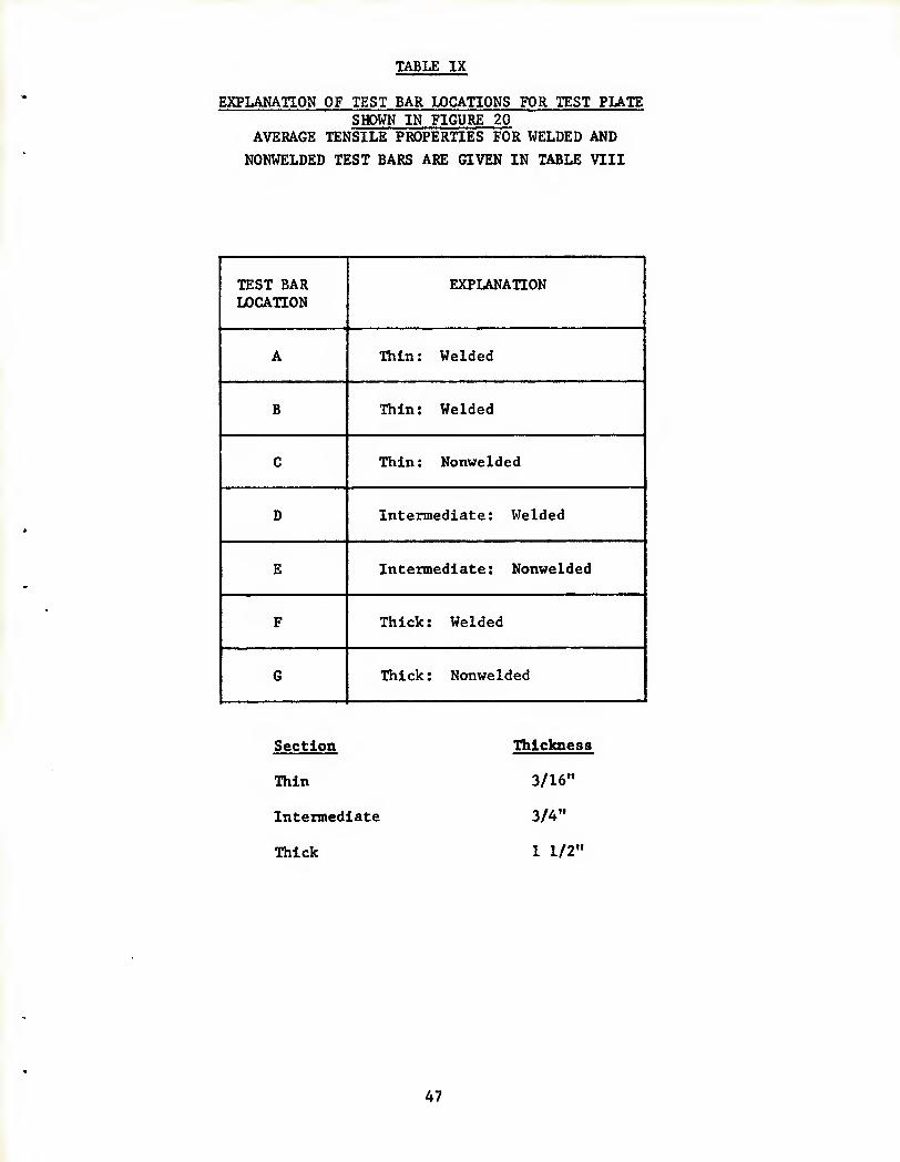
TABLE IX
EXPLANAnON OF TEST BAR LOCATIONS FOR TEST PLATE SHOWN IN FIGURE 20
AVERAGE TENSILE PROPERTIES FOR WELDED AND
NONWELDED TEST BARS ARE GIVEN IN TABLE VIII
TEST BAR LOCATION
EXPLANATION
A ■Riiin: Welded
B Thin: Welded
C Thin: Nonwelded
D Intermediate: Welded
E Intermediate: Nonwelded
F Thick: Welded
6 Thick: Nonwelded
Section
Thin
Intermediate
Thick
Thtcknest
3/16"
3/4"
1 1/2"
47

TABLE X
TENSILE PROPERTIES OF MACHINED TEST BARS CUT FROM
HLH COMBINER HOUSING
PHASE - II
Test Bar
Number
(Fig. 10)
Section
Thickness
(Inch)
Location:
Chill/Riser/
Neutral
T.S.
(PSI)
Y.S.
(PSI)
Elongation
a) Brinell Hardness
(500 kg load, 10
mm. ball)
TEST BARS TAKEN FROM NONWELDED AKEAS
1 3" Intermediate:
Between Riser & Chill
24,221 15,015 3.0 51.8
2 3" Intermediate:
Between Riser & Chill
23,504 15,283 4.0 55.1
3 0.48" Neutral 25,121 15,894 4.5 55.1
4 0.42" Neutral 22,803 15,335 3.5 56.8
5 0.40" Neutral 22,571 15,943 3.0 56.8
6 0.40" Neutral 26,951 17,268 5.0 55.1
7 0.45" Neutral 25,035 15,425 4.0 58.6
8 0.45" Neutral 25,581 16,567 4.0 53.4
9 2.75" Riser 21,183 15,261 3.0 55.1
10 0.31" Neutral 23,326 14,903 3.0 56.8
11 0.30" Neutral 24,111 15,353 3.5 55.1
16 1.21 Intermediate:
Between 24,489 15,472 4.0 55.1
17 1.3", 1.6" Intermediate:
Between Rispr f. nhm
25,560 15,432 4.0 58.6
18 0.4" Neutral 24,903 14,929 4.0 53.4
19 0.3", 0.5" Neutral 22,916 15,000 3.5 56.8
20 0.3" Neutral 25,153 15,000 4.0 53.4
23 0.45" Near Riser 27,557 16,941 5.5 55.1
TEST BARS TAKHN FROM SEGREGATION AREAS
21 0.35" Near Riser 23,513 15,176 3.5 56.8
22 0.35" Neutral 23,750 16,590 3.0 55.1
48

TABLE X (CONT'D)
TENSILE PROPERTIES OF MACHINED TEST BARS CUT FROM
HLH COMBINER HOUSING
PHASE - II
Test Bar
Number
(Fig. 10)
Section
Thickness
(Inch)
Location:
Chill/Riser/
Neutral
T.S.
(PSI)
Y.S.
(PSI)
Elongation
(%)
Brinell Hardness
(500 kg load, 10
mm. ball)
TEST BARS TAKEN FROM WELDED AREAS
24 0.35" 21,460 15,241 3.5 53.4
25 0.27" 24,755 16,447 3.5 56.8
26 0.35" 24,275 14,190 3.5 55.1
27 2.0" 22,900 16,779 3.0 56.8
28 0.62" 25,707 16,156 4.0 58.6
29 1.60" — 23,471 15,834 4.0 55.1
30 1.0" 22,609 16,119 2.5 58.6
31 1.0" 22,973 16,565 2,5 53.4
32 0.45", 1.5" 26,887 16,500 4.0 53.4
33 0.3" 26,439 16,979 4.5 55.1
34 0.4",0.6",0.8" 26,682 15,981 5.0 53.4
TEST BARS TAKEN FROM CHILLED AREAS
35 1.3" Chill 25,965 17,109 2.0 58.6
36 1.5" Chill 24,924 14,591 4.0 58.6
37 1.0" Chill 25,680 15,648 4.2 56.8
38 1.8" Chill 23,517 16,550 2.0 56.8
39 1.25" Chill 24,576 16,525 4.0 56.8
TEST BARS MACHINED FROM CAST APPENDAGES
■■ «• 0.5" Chill 27,088 15,527 5.0 --
— 0.5" Chill 27,313 15,723 6.5 —
49

TABLE X (CONT'D)
TENSILE PaOPERTIES OF MACHINED TEST BARS CUT FiEODM
HLH COMBINER HOUSING
PHASE - II
AVERAGE TENSILE PROPERTIES OF VARIOUS AREAS
Test Bar Location AVERAGE TENSILE PROPERTIES
T.S.
(PSI)
Y.S.
(PSI)
ELONGATION
(%)
Nonwelded Areas 24,410 15,590 3.8
Segregation Areas
(detected in x-ray) 23,632 15,883 3.2
Welded Areas 24,378 16,072 3.6
Chilled Areas 24,932 16,085 3.2
Cast Appendages 27,201 15,625 5.7
NOTES: (1) See Figures 12 to 15 for test bar locations.
(2) Tensile properties of test bars taken from thick sections
and riser locations are slightly lower than thin sections
and chilled locations. But, in general, the tensile pro-
perties of different test bars are quite similar.
(3) (a) All the nonwelded test bars were taken from the middle of the section thickness.
(b) All the welded test bars were taken from the weld surfaces.
(c) All the chilled test bars were taken from the chilled
surfaces.
50

TABLE XI
TENSILE PROPERTIES OF TEST BARS MACHINED FROM AREAS OF
TEST PLATE CONTAINING FLOW-LINE TYPE OF SEGREGATION
Flow-line type of segregation resulted from welding of a thin area on
the edge of the test plate using multiple passes (weld area number
eight (8) in Figure - 19). Tensile properties of the test bars
machined from this area are given below, along with the tensile pro-
perties of test bars machined from an adjacent nonwelded, sound area
of identical thickness. The following results are for eight different
heat treatments (Table II), for chemical composition number 5 (Table I),
HEAT TREATMENT
(Fl<
T.S. (PSI)
DEFECTIVE 3w-line Sag
Y.S. (PSI)
AREA regation)
ELONGATION (%)
DEFECT
T.S. (PSI)
FREE. S(
Y.S. (PSI)
)UND AREA
ELONGATION (%)
HI 30,849 22,058 3.5 30,794 22,476 3.0
H2 30,260 20,790 3.0 30,369 22,860 3.0
H3 29,818 20,605 4.0 28,213 22,144 3.0
H4 28,850 21,818 3.0 30,135 22,642 3.0
H5 31,565 20,308 4.0 30,105 23,274 2.5
H6 30,026 21,841 2.5 27,218 22,740 2.0
H7 26,421 20,274 2.0 25,587 22,530 3.0
H8 31,973 20,043 5.0 28,404 22,340 3.5
51
DISTRIBUTION
Commander US Army Armament Command Rock Island IL 61201
Attn: AMXPE-MT, G. Ney
Director Air Force Materials Laboratory Attn: AFML, Technical Library Wright Patterson AFB Dayton OH 45433
Commander Wright-Patterson Air Force Base Dayton OH 45433
Commander US Army Material, Development & Readiness Command 5001 Eisenhower Av Alexandria VA 22333
1 Attn:
1 Attn:
1 Attn:
1 Attn:
DRCDE-A L. Groan
DRCDMD
DRGDMR
DRCDMD-T
1 Attn: DRCDE-F Foreign Science & Technology
1 Attn:
1 Attn:
DRCDE-W
DRCMT
Commander US Army Ballistic Research Lab. Aberdeen Proving Ground MD 21005
Attn: Technical Information Div.
Commander US Army Eglin Air Force Base FL 32542
Attn: AFATL-DLOU, A. Lopez
Commander Picatinny Arsenal Dover NJ 07801
1 Attn: SARPA-AD
1 Attn: Technical Information Division
Commander Watervliet Arsenal Materials Engineering Division Watervliet NY 12189
Attn: Technical Information Division
Commander Andrews Air Force Base MD 20331
1 Attn
1 Attn: Hq AFSC-INA
Hq AFSC-SDW, R. W. Hartmeyer
Commander Air University Library Maxwell Air Force Base AL 36112
Commander Rock Island Arsenal Attn: Technical Information Division Rock Island IL 61201
52
^J.V.)V'.l
Commander Army Materials & Mechanincs Research Center Watertown MA 02172
Attn: Technical Information Div.
Commander Office of Naval Research Dept. of the Navy Attn: 423 Washington DC 20025
Commander US Army Research Office PO Box 12211 Attn: Dr. George Mayer, Director
Metallurgy & Materials Science Division
Research Triangle Park NC 27709
Commander Frankford Arsenal Philadelphi PA 19137
1 Attn: SARFA-TD
1 Attn: SARFA-CE
1 Attn: PD
1 Attn: PD, Mr. G. White
3 Attn: PDM, J. D. Corrie
1 Attn: PIM-A, A. Gallaccio
7 Attn: PIM-P, R. E. Edelman
3 Attn: SARFA-TSP-L/51-2 1-Reference copy 1-Circulation copy 1-Tech Rpts Editing
Commander Naval Air Development Center Johnsville, Aero Materials Dept. Attn: Mr. Forrest Williams Warminster PA 18974
Aerospace Corporation Attn: E. G. Kendall El Segundo CA 90245
Director National Academy of Science Attn: Materials Advisory Board 2101 Constitution Av NW Washington DC 20418
Metals & Ceramic Information Center Battelle Memorial Institute 505 King Av Columbus OH 43201
Defense Documentation Center Cameron Station Alexandria VA 22314
(5)
Commander US Army Aviation Systems Command PO Box 209 St. Lousi MO
15 Attn: DRSAV-LEP J. Thorp
1 Attn: DRCPM-IAP-T J. Chevalier
1 Attn: DRSAV-EQA W. McClane
Mr. John Fody P38-21 Boeing-Vertol Company Box 16858 Philadelphia PA 19142
Mr. Irian S. Reasor, Jr. Bell Helicopter Textron Dept. 81 PLT5A PO Box 482 Ft. Worth TX 76101
53

■^'HDL-J^WijIB'
Mr. Glenn E. Lattin # Chief, Materials Engineering Sikorsky Aircraft Stratford CT 06602 *
Mr. John C. French Hughes Helicopters Division of Sunma Corp. Centlnela Av at Teal St Culver City CA 90230
Mr. Jeremy J. Walters Manager, Materials Lab. AVCO Lycoming Division 550 S Main St Stratford CT 06602
54