Embed Size (px)
Citation preview
Final Report by Power Transformers Evaluation Standards Subcommittee, Energy Efficiency Standards Subcommittee of the Advisory Committee for Natural
Resources and Energy
Data 5
December, 2011
Ministry of Economy, Trade and Industry
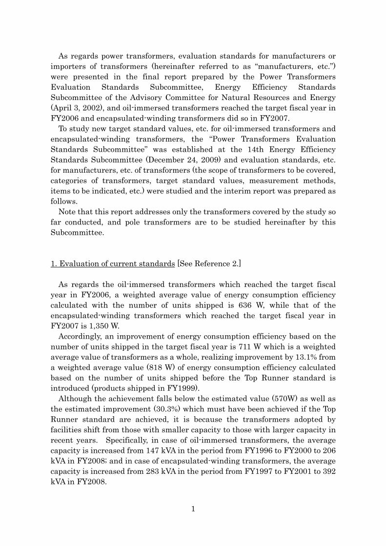
As regards power transformers, evaluation standards for manufacturers or importers of transformers (hereinafter referred to as “manufacturers, etc.”) were presented in the final report prepared by the Power Transformers Evaluation Standards Subcommittee, Energy Efficiency Standards Subcommittee of the Advisory Committee for Natural Resources and Energy (April 3, 2002), and oil-immersed transformers reached the target fiscal year in FY2006 and encapsulated-winding transformers did so in FY2007.
To study new target standard values, etc. for oil-immersed transformers and encapsulated-winding transformers, the “Power Transformers Evaluation Standards Subcommittee” was established at the 14th Energy Efficiency Standards Subcommittee (December 24, 2009) and evaluation standards, etc. for manufacturers, etc. of transformers (the scope of transformers to be covered, categories of transformers, target standard values, measurement methods, items to be indicated, etc.) were studied and the interim report was prepared as follows.
Note that this report addresses only the transformers covered by the study so far conducted, and pole transformers are to be studied hereinafter by this Subcommittee. 1. Evaluation of current standards [See Reference 2.]
As regards the oil-immersed transformers which reached the target fiscal year in FY2006, a weighted average value of energy consumption efficiency calculated with the number of units shipped is 636 W, while that of the encapsulated-winding transformers which reached the target fiscal year in FY2007 is 1,350 W.
Accordingly, an improvement of energy consumption efficiency based on the number of units shipped in the target fiscal year is 711 W which is a weighted average value of transformers as a whole, realizing improvement by 13.1% from a weighted average value (818 W) of energy consumption efficiency calculated based on the number of units shipped before the Top Runner standard is introduced (products shipped in FY1999).
Although the achievement falls below the estimated value (570W) as well as the estimated improvement (30.3%) which must have been achieved if the Top Runner standard are achieved, it is because the transformers adopted by facilities shift from those with smaller capacity to those with larger capacity in recent years. Specifically, in case of oil-immersed transformers, the average capacity is increased from 147 kVA in the period from FY1996 to FY2000 to 206 kVA in FY2008; and in case of encapsulated-winding transformers, the average capacity is increased from 283 kVA in the period from FY1997 to FY2001 to 392 kVA in FY2008.
1
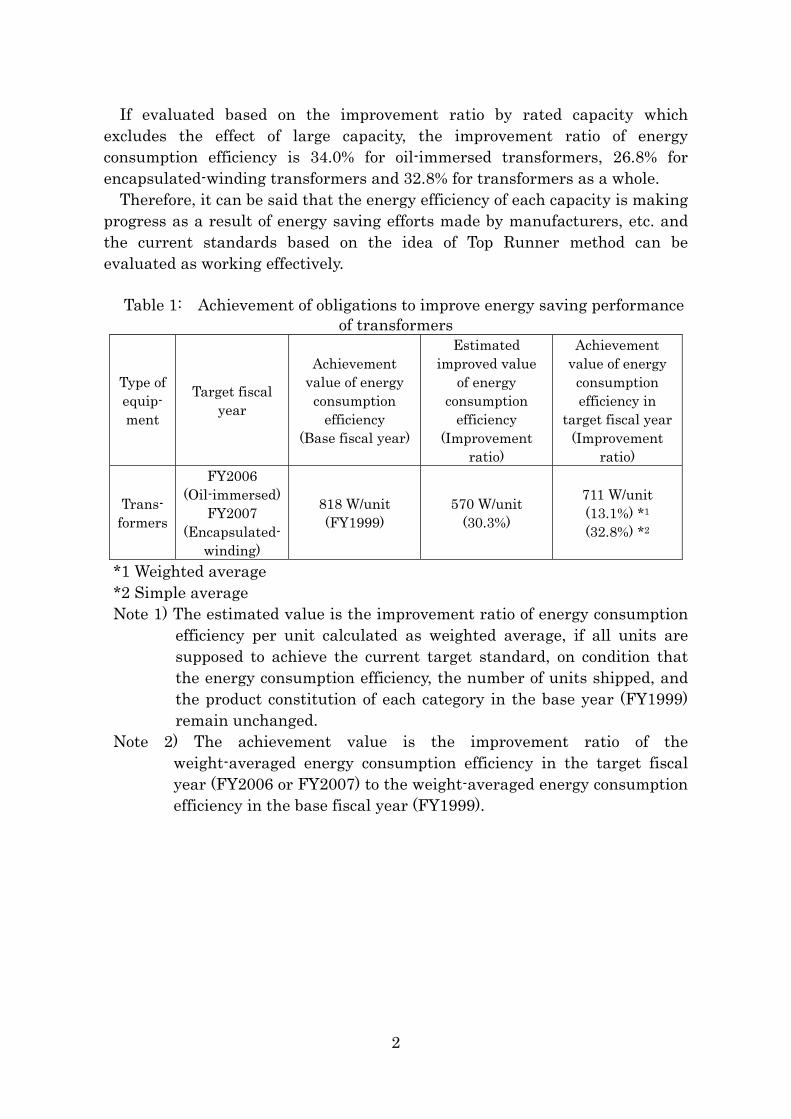
If evaluated based on the improvement ratio by rated capacity which excludes the effect of large capacity, the improvement ratio of energy consumption efficiency is 34.0% for oil-immersed transformers, 26.8% for encapsulated-winding transformers and 32.8% for transformers as a whole.
Therefore, it can be said that the energy efficiency of each capacity is making progress as a result of energy saving efforts made by manufacturers, etc. and the current standards based on the idea of Top Runner method can be evaluated as working effectively.
Table 1: Achievement of obligations to improve energy saving performance of transformers
Type of equip- ment
Target fiscal year
Achievement value of energy
consumption efficiency
(Base fiscal year)
Estimated improved value
of energy consumption
efficiency (Improvement
ratio)
Achievement value of energy
consumption efficiency in
target fiscal year (Improvement
ratio)
Trans- formers
FY2006 (Oil-immersed)
FY2007 (Encapsulated-
winding)
818 W/unit (FY1999)
570 W/unit (30.3%)
711 W/unit (13.1%) *1
(32.8%) *2
*1 Weighted average *2 Simple average Note 1) The estimated value is the improvement ratio of energy consumption
efficiency per unit calculated as weighted average, if all units are supposed to achieve the current target standard, on condition that the energy consumption efficiency, the number of units shipped, and the product constitution of each category in the base year (FY1999) remain unchanged.
Note 2) The achievement value is the improvement ratio of the weight-averaged energy consumption efficiency in the target fiscal year (FY2006 or FY2007) to the weight-averaged energy consumption efficiency in the base fiscal year (FY1999).
2
2. Target scope [See Attachment 1.]
The same for the current standards, transformers to be covered shall be those whose rated primary voltage is above 600 V and 7,000 V or below and which are connected to alternating current circuit.
Also the same for the current standards, the following transformers are excluded from the application of specified equipment. 1) Those using gas as insulation material (Gas-immersed transformers) 2) Those using H class insulation material (H class insulation dry-type
transformers) 3) Scott-connected transformers 4) Those with 3 or more windings (Multi-winding transformers) 5) Pole transformers 6) Those which are single-phase transformers and whose rated capacity is 5
kVA or below, or above 500 kVA 7) Those which are three-phase transformers and whose rated capacity is 10
kVA or below, or above 2,000 kVA 8) Those which are three-phase transformers using insulation material made
of resin and used to transform three phase alternating current into single phase alternating current and three phase alternating current (Double power encapsulated-winding transformers)
9) Those whose rated secondary voltage is below 100 V or above 600 V 10) Those which are air-cooled type or water-cooled type 3. Matters to be evaluation standards for manufacturers, etc. (1) Target fiscal year [See Attachment 2.]
The target fiscal year for transformers shall be FY2014 for both oil-immersed transformers and encapsulated-winding transformers.
(2) Categories and target standard values for setting targets [See Attachment 3
to 4.] As regards transformers shipped by manufacturers, etc. of transformers
in Japan in the target fiscal year, the value obtained from weight-averaging energy consumption efficiency measured using the method described in paragraph (3) with the number of units shipped by each manufacturer for each category in the table below shall not exceed the target standard values.
3
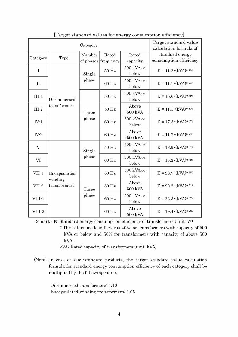
[Target standard values for energy consumption efficiency]
Category
Category Type Number of phases
Rated frequency
Rated capacity
Target standard value calculation formula of
standard energy consumption efficiency
I 50 Hz 500 kVA or below E = 11.2・(kVA)0.732
II
Single phase
60 Hz 500 kVA or below E = 11.1・(kVA)0.725
III-1 50 Hz 500 kVA or below E = 16.6・(kVA)0.696
III-2 50 Hz Above 500 kVA E = 11.1・(kVA)0.809
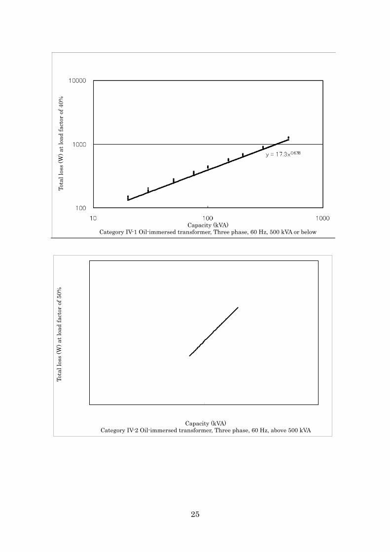
IV-1 60 Hz 500 kVA or below E = 17.3・(kVA)0.678
IV-2
Oil-immersed transformers
Three phase
60 Hz Above 500 kVA E = 11.7・(kVA)0.790
V 50 Hz 500 kVA or below E = 16.9・(kVA)0.674
VI
Single phase
60 Hz 500 kVA or below E = 15.2・(kVA)0.691
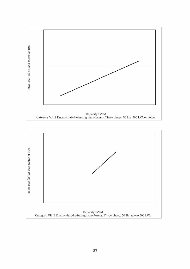
VII-1 50 Hz 500 kVA or below E = 23.9・(kVA)0.659
VII-2 50 Hz Above 500 kVA E = 22.7・(kVA)0.718
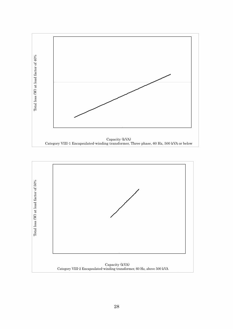
VIII-1 60 Hz 500 kVA or below E = 22.3・(kVA)0.674
VIII-2
Encapsulated-winding transformers
Three phase
60 Hz Above 500 kVA E = 19.4・(kVA)0.737
Remarks E: Standard energy consumption efficiency of transformers (unit: W) * The reference load factor is 40% for transformers with capacity of 500
kVA or below and 50% for transformers with capacity of above 500 kVA.
kVA: Rated capacity of transformers (unit: kVA)
(Note) In case of semi-standard products, the target standard value calculation formula for standard energy consumption efficiency of each category shall be multiplied by the following value.
Oil-immersed transformers: 1.10 Encapsulated-winding transformers: 1.05
4
(3) Method for measuring energy consumption efficiency [See Attachment 5.] Energy consumption efficiency of transformers in II. (2) shall be “total loss
(W)” and calculated by the following formula; the no load loss (W) and the load loss (W) shall be measured using the method prescribed by JIS C 4304 and JIS C 4306.
Total loss (W) = No load loss (W) + × Load loss (W)
Where, the following values shall be used for m. m: Reference load factor
Transformers whose capacity is 500 kVA or below 40 (%) Transformers whose capacity is above 500 kVA 50 (%)
(4) Display items, etc.
1) Display items Following items shown from i) to x) shall be specified as display items
regarding energy consumption efficiency of transformers, the same as those for the current standards.
i) Product name and model name ii) Type of transformer (structure) (oil-immersed or
encapsulated-winding) iii) Rated capacity (kVA) iv) Number of phases v) Rated frequency (Hz) vi) Rated primary voltage and rated secondary voltage (V) vii) Energy consumption efficiency (total loss (W)) viii) Reference load factor (%) ix) Standard name (standard (JIS standard or JEM standard) or
semi-standard) x) Name of manufacturer, etc.
5
2) Compliance items
Followings shall be compliance items regarding energy consumption efficiency of transformers, the same as those for the current standards. - Energy consumption efficiency (total loss W) said in item vii) of
paragraph 1) above shall be indicated to 3 or more significant figures (however, 2 or more significant figures if the efficiency is below 100 W).
- Reference load factor (%) said in item viii) of paragraph 1) above shall be the value prescribed in the foregoing paragraph (3) in integers.
- Display items listed in paragraph 1) above shall be indicated in an indelible way on noticeable spots in catalogues describing the performance of transformers and in materials presented by manufacturers, etc. when consumers selecting products.
4. Proposals, etc. for energy conservation (1) Actions of Government
From the viewpoint of promoting the spread of transformers with excellent energy consumption efficiency, the government shall make efforts to take necessary actions such as the spread and enlightenment activities, in order to promote actions of users and manufacturers, etc.
(2) Actions of manufacturers, etc.
1) Efforts shall be made to promote technological development for further energy efficiency of transformers and to develop products with excellent energy consumption efficiency.
2) From the viewpoint of promoting the spread of transformers with excellent energy consumption efficiency, efforts shall be made to provide appropriate information so that users can select transformers with excellent energy consumption efficiency, by means of, for example, indicating energy consumption efficiency not only on catalogues and user manuals but also on easily noticeable spots in materials which manufacturers, etc. will present to help users select transformers.
(3) Actions of users
Efforts shall be made not only to select transformers with excellent energy consumption efficiency and adequate capacity, but also to promote energy conservation by using transformers correctly and efficiently.
6
Attachment 1
Scope of Power Transformers Covered 1. Basic ideas
Transformers covered in this study shall be those whose rated primary voltage is above 600 V and 7,000 V or below and which are used in alternating current circuit. Applicable scope shall include not only transformers with standard specifications whose capacity, voltage, etc. are prescribed by JIS, etc. but also transformers with non-standard specifications (semi-standard products). 2. Transformers excluded out of the scope (1) Those using gas as insulation material (Gas-immersed transformers)
Transformers using sulfur hexafluoride which is one of greenhouse gases as the base material of insulation. Production of these transformers has been curtailed because emission of the gas must be contained. (The number of units shipped in FY2009 is 0.)
(2) Those using H class insulation material (H class insulation dry-type
transformers) Dry-type transformers which use heat resistant class H (tolerable
maximum temperature 180°C) prescribed by JIS C4003 “Thermal evaluation and classification of electrical insulation” as main insulation base material and whose surfaces are varnished. They had been used as emergency transformers before encapsulated-winding transformers were introduced. Shipment of these transformers decreased as encapsulated-winding transformers spread because their withstand voltage is lower than that of oil-immersed types as well as because they require more frequent maintenance than encapsulated-winding types for their poor dust proof and humidity resistance performance. (The number of units shipped in FY2009 is 0.)
(3) Scott-connected transformers
Transformers which transform three phase alternating current into two phase and can take single phase load from each of them. When a single phase alternating current load is taken from a three phase alternating current, unbalanced voltage which affects the primary side is generated; therefore, Scott-connected transformers are used to minimize this impact. Because of the volumetric efficiency, they are mainly used for small-scale facilities such as emergency power supply systems in buildings and factories, etc. in addition to the usage for electric railway signals. However, the demand for this type of transformers is not much, compared to the shipment of transformers as a whole. (The number of units shipped in FY2009 is 388.)
7
(4) Those with 3 or more windings (Multi-winding transformers) Transformers whose winding capacity is designated for each product and
which are used for special usage such as where one unit supplies two or more types of voltage to the secondary side. As a standard product is equipped with two windings, the voltage supplied to the secondary side is limited to one type only, but, in some cases, a product is equipped with multiple windings such as three or four if multiple voltage supplies are required in factories, etc. The demand for this type is not much in the shipment of transformers as a whole. (The number of units shipped in FY2009 is 84.)
(5) Those which are single-phase transformers and whose rated capacity is 5 kVA
or below, or above 500 kVA Small capacity products are frequently used for the usage other than
distribution of electricity, such as usage for the control of breakers, protection relays, maintenance lights, etc. or for railway signals. As for large capacity products, the demand is low due to constraints to the capacity and voltage fluctuation affecting power supply of large current breakers used together, etc. (The number of units shipped in FY2009 is 119 in case of capacity 5 kVA or below and 16 in case of capacity above 500 kVA.)
(6) Those which are three-phase transformers and whose rated capacity is 10 kVA
or below or above 2,000 kVA Small capacity products are used as power supplies for motors, etc. whose
load is minimal. As for large capacity products, the main application is as power supplies of places where electric power loads are concentrated such as large-scale plants; however, there is no general versatility with these products for constraints to large current breakers, etc., so the demand for this type of transformers is not much. (The number of units shipped in FY2009 is 83 in case of capacity 10 kVA or below, and 149 in case of capacity above 2,000 kVA.)
(7) Those which are three-phase transformers using resin insulation material and
used to transform three phase alternating current into single phase alternating current and three phase alternating current (Double power encapsulated-winding transformers)
For the use with small cubicle-type power receiving and distributing facilities for both lighting and powering, oil-immersed transformers are mainly used. Thus, from the aspect of price, the demand for encapsulated-winding transformers is not much. (The number of units shipped in FY2009 is 44.)
(8) Those whose rated secondary voltage is below 100 V or above 600 V
Transformers used as power supplies for equipment such as imported products designed to operate on a rated voltage which is different from the one generally used in Japan. The demand for this type of transformers is not much in the shipment of transformers as a whole. (The number of units shipped in FY2009 is 212.)
8
(9) Air-cooled type transformers and water-cooled type transformers Most of air-cooled transformers are large capacity models used for power
stations and substations as well as for special high voltage power receiving and distributing, etc., and the demand for this type of transformers whose capacity is below 2,000 kVA is not much. (The number of units shipped in FY2009 is 1.)
Water-cooled type transformers are mainly used for electric furnaces, but the demand for this type of transformers for the purpose of high voltage power receiving and distributing is not much. (The number of units shipped in FY2009 is 0.)
9
Attachment 2
Target Fiscal Year, etc. of Power Transformers 1. Target fiscal year
Major improvement of energy consumption efficiency of transformers is mainly made when the efficiency standards of laws, standards, specifications, etc. are changed following the improvement of energy saving technologies or materials. Since the model change of transformers is made at the interval of 7 to 8 years, it is thought necessary to give opportunities for transformers to improve energy consumption efficiency at least once or twice in order to realize a drastic improvement in the energy consumption efficiency.
In light of the above, it is appropriate to set the target fiscal year of transformers as FY2014 which is 8 years after FY2006, the target fiscal year of the current standards for oil-immersed transformers.
Meanwhile, although the target fiscal year for the current standards for encapsulated-winding transformers has been set differently from that for oil-immersed transformers, it is appropriate to set the next target fiscal year as FY2014, the same as for the oil-immersed transformers, for early energy efficiency improvement. 2. Improvement achieved in target fiscal year
The improvement ratio of energy consumption efficiency (total loss (W)) in the target fiscal year is estimated as 12.5% against the current target standard value on the premise of that the number of units shipped and the product constitution of each category in FY2009 remain unchanged. <Summary of estimation> (1) Energy consumption efficiency per unit (total loss (W)) derived from
weight-averaging the target standard values for the transformers shipped in FY2009 with the number of units shipped.
Approximately 596.1 W/unit
10
(2) Energy consumption efficiency per unit (total loss (W)) derived from
weight-averaging the target standard values for the transformers assumed to be shipped in the target fiscal year with the number of units shipped.
Approximately 521.8 W/unit
* As a prerequisite, the number of units to be shipped and the product
constitution are the same as in FY2009. (3) Improvement ratio of energy consumption efficiency 596.1 W/unit − 521.8 W/unit 596.1 W/unit = Approximately 12.5%
11
Attachment 3
Categories for Setting Targets for Power Transformers 1. Basic ideas
Transformers shall be classified based on the principles referred to as “the basic idea concerning the development and revision of evaluation standards for manufacturers, etc. to be considered in relation to the improvement in performance of specific equipment” (the 10th Energy Efficiency Standards Subcommittee of the Advisory Committee for Natural Resources and Energy, revised on June 18, 2007) (hereinafter referred to as “the principles”).
“The basic idea concerning the development and revision of evaluation standards for manufacturers, etc. to be considered in relation to the improvement in performance of specific equipment” - Extract - Principle 2: Specific equipment is classified based on certain indices. The indices
(basic indices) are those which are deeply related to energy consumption efficiency such as physical amount and functions, and they are determined considering factors which consumers use as standards when choosing products (factors representing consumers’ needs).
Principle 3: Target standard value is determined by one value or functional formula for each category based on the basic indices, where it is feasible and appropriate to target at the same energy consumption efficiency.
Principle 4: When setting categories, additional functions are disregarded in principle. However, if the energy consumption efficiency of a product without a certain additional function is set as a target standard value, other products with additional functions may withdraw from the market, despite that market needs for the latter products are thought to be high, because they cannot comply with the target standard value. If the probability of such case is high, then it is acceptable to make another category (sheet) for those products.
Principle 5: As regards products which are expensive but excellent in energy consumption efficiency because they use advanced energy saving technologies, although it is possible to classify them into separate categories, it is desirable to treat them in the same category with others wherever possible so that manufacturers can actively sell the products with excellent energy consumption efficiency.
Principle 6: When setting a target standard value for a category, special products shall be excluded. However, availability of technologies employed in such special products shall be also reviewed when studying the future efficiency improvement possibly realized by technology development, etc.
12
2. Specific classification method
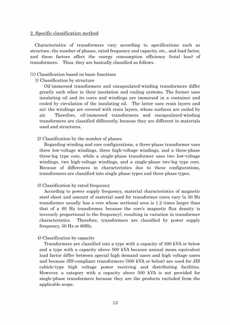
Characteristics of transformers vary according to specifications such as structure, the number of phases, rated frequency and capacity, etc., and load factor, and these factors affect the energy consumption efficiency (total loss) of transformers. Thus, they are basically classified as follows. (1) Classification based on basic functions
1) Classification by structure Oil-immersed transformers and encapsulated-winding transformers differ greatly each other in their insulation and cooling systems. The former uses insulating oil and its cores and windings are immersed in a container and cooled by circulation of the insulating oil. The latter uses resin layers and air; the windings are covered with resin layers, whose surfaces are cooled by air. Therefore, oil-immersed transformers and encapsulated-winding transformers are classified differently, because they are different in materials used and structures.
2) Classification by the number of phases Regarding winding and core configurations, a three-phase transformer uses three low-voltage windings, three high-voltage windings, and a three-phase three-leg type core, while a single-phase transformer uses two low-voltage windings, two high-voltage windings, and a single-phase two-leg type core. Because of differences in characteristics due to these configurations, transformers are classified into single phase types and three phase types.
3) Classification by rated frequency According to power supply frequency, material characteristics of magnetic steel sheet and amount of material used for transformer cores vary (a 50 Hz transformer usually has a core whose sectional area is 1.2 times larger than that of a 60 Hz transformer, because the core’s magnetic flux density is inversely proportional to the frequency), resulting in variation in transformer characteristics. Therefore, transformers are classified by power supply frequency, 50 Hz or 60Hz.
4) Classification by capacity Transformers are classified into a type with a capacity of 500 kVA or below and a type with a capacity above 500 kVA because annual mean equivalent load factor differ between special high demand users and high voltage users and because JIS-compliant transformers (500 kVA or below) are used for JIS cubicle-type high voltage power receiving and distributing facilities. However, a category with a capacity above 500 kVA is not provided for single-phase transformers because they are the products excluded from the applicable scope.
13
(2) Classification by voltage, connection, or other specifications
Semi-standard products whose voltage and connection are different from the JIS standard are generally made based on standard products but by means of modifying the optimized design of standard products, so the characteristics of semi-standard transformers are inferior to those of standard transformers. Besides, reducing the loss of semi-standard products to the level of standard products will result in increased costs due to increases in the number of wire types as well as in the number of jigs for production of cores and windings.
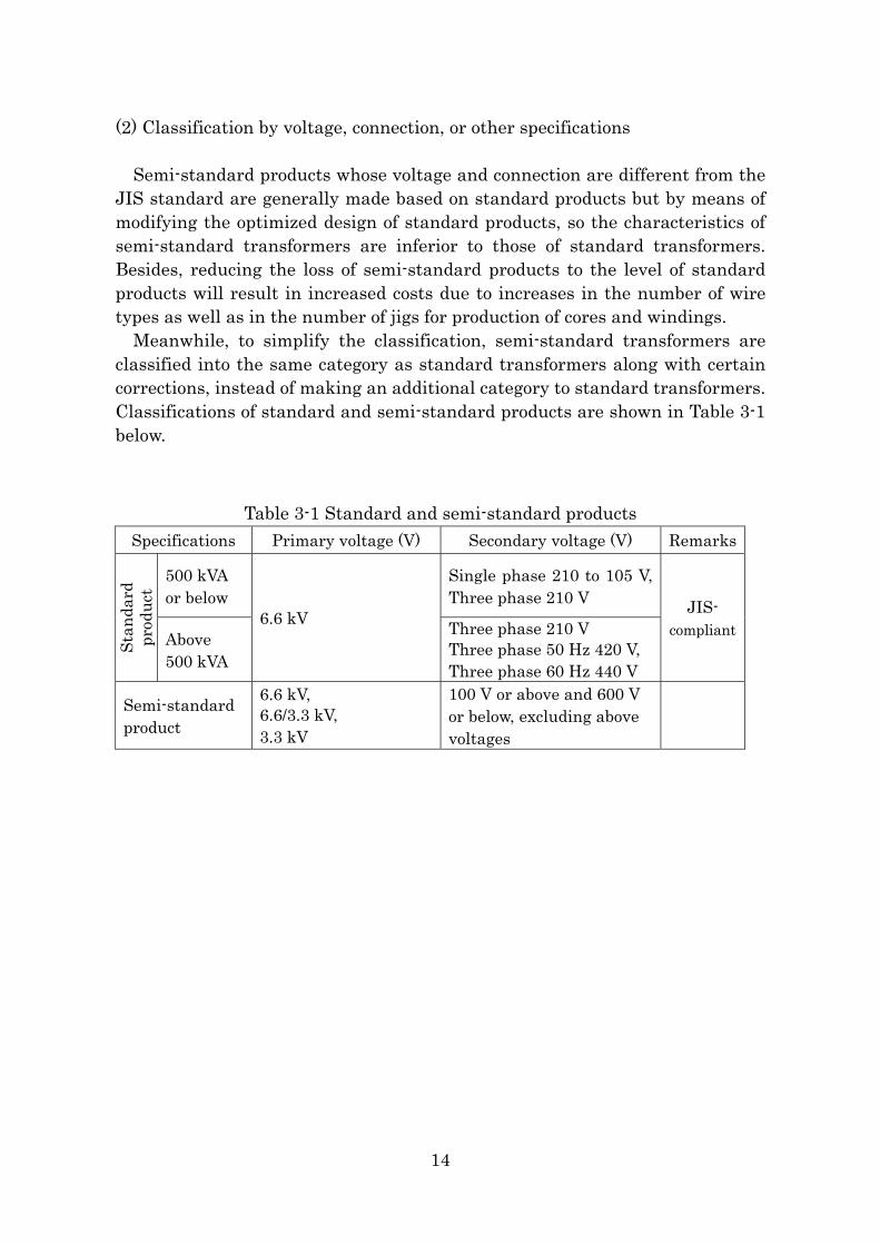
Meanwhile, to simplify the classification, semi-standard transformers are classified into the same category as standard transformers along with certain corrections, instead of making an additional category to standard transformers. Classifications of standard and semi-standard products are shown in Table 3-1 below.
Table 3-1 Standard and semi-standard products Specifications Primary voltage (V) Secondary voltage (V) Remarks
500 kVA or below
Single phase 210 to 105 V, Three phase 210 V
Stan
dard
pr
oduc
t
Above 500 kVA
6.6 kV Three phase 210 V Three phase 50 Hz 420 V, Three phase 60 Hz 440 V
JIS- compliant
Semi-standard product
6.6 kV, 6.6/3.3 kV, 3.3 kV
100 V or above and 600 V or below, excluding above voltages
14
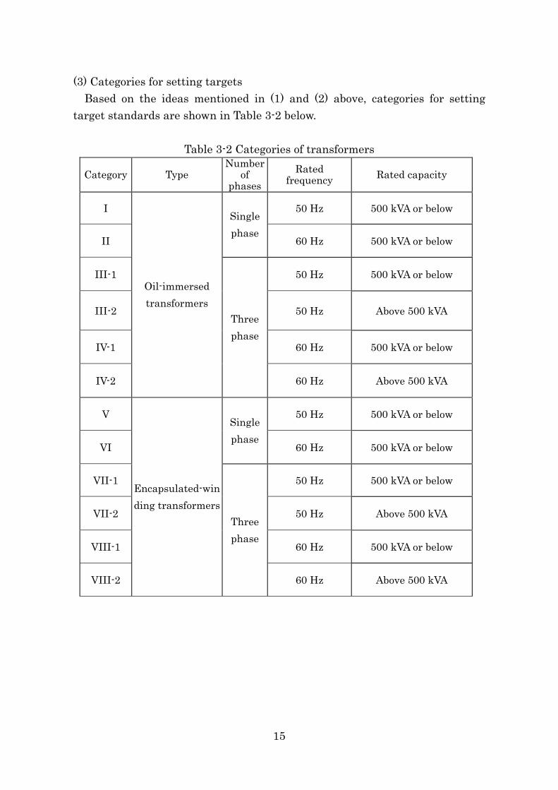
(3) Categories for setting targets Based on the ideas mentioned in (1) and (2) above, categories for setting
target standards are shown in Table 3-2 below.
Table 3-2 Categories of transformers
Category Type Number
of phases
Rated frequency Rated capacity
I 50 Hz 500 kVA or below
II
Single phase
60 Hz 500 kVA or below
III-1 50 Hz 500 kVA or below
III-2 50 Hz Above 500 kVA
IV-1 60 Hz 500 kVA or below
IV-2
Oil-immersed transformers
Three phase
60 Hz Above 500 kVA
V 50 Hz 500 kVA or below
VI
Single phase
60 Hz 500 kVA or below
VII-1 50 Hz 500 kVA or below
VII-2 50 Hz Above 500 kVA
VIII-1 60 Hz 500 kVA or below
VIII-2
Encapsulated-winding transformers
Three phase
60 Hz Above 500 kVA
15
Attachment 4
Target Standard Values for Power Transformers 1. Basic ideas
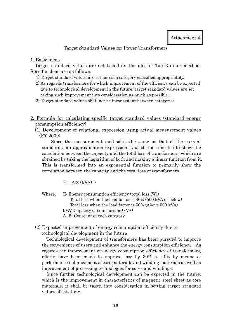
Target standard values are set based on the idea of Top Runner method. Specific ideas are as follows.
1) Target standard values are set for each category classified appropriately. 2) As regards transformers for which improvement of the efficiency can be expected
due to technological development in the future, target standard values are set taking such improvement into consideration as much as possible.
3) Target standard values shall not be inconsistent between categories. 2. Formula for calculating specific target standard values (standard energy
consumption efficiency) (1) Development of relational expression using actual measurement values
(FY 2009) Since the measurement method is the same as that of the current
standards, an approximation expression is used this time too to show the correlation between the capacity and the total loss of transformers, which are obtained by taking the logarithm of both and making a linear function from it. This is transformed into an exponential function to primarily show the correlation between the capacity and the total loss of transformers.
E = A × (kVA) B
Where, E: Energy consumption efficiency (total loss (W)) Total loss when the load factor is 40% (500 kVA or below) Total loss when the load factor is 50% (Above 500 kVA)
kVA: Capacity of transformer (kVA) A, B: Constant of each category
(2) Expected improvement of energy consumption efficiency due to
technological development in the future Technological development of transformers has been pursued to improve
the convenience of users and enhance the energy consumption efficiency. As regards the improvement of energy consumption efficiency of transformers, efforts have been made to improve loss by 30% to 40% by means of performance enhancement of core materials and winding materials as well as improvement of processing technologies for cores and windings.
Since further technological development can be expected in the future, which is the improvement in characteristics of magnetic steel sheet as core materials, it shall be taken into consideration in setting target standard values of this time.
16
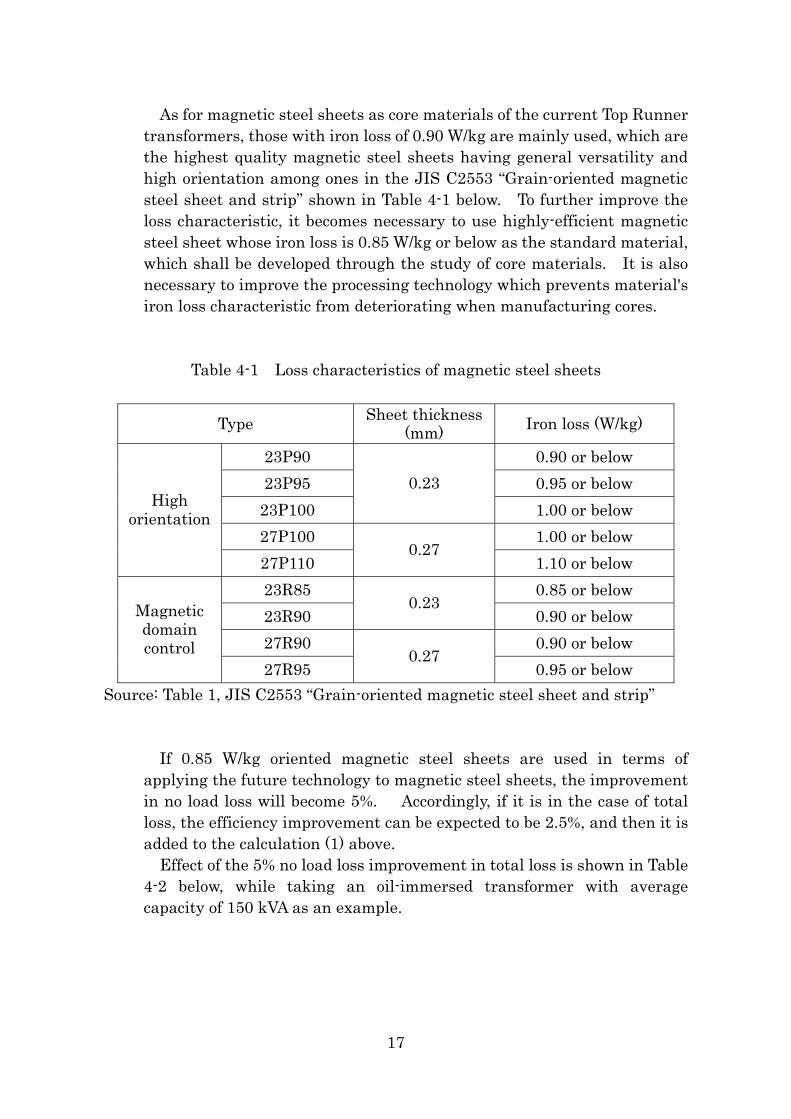
As for magnetic steel sheets as core materials of the current Top Runner transformers, those with iron loss of 0.90 W/kg are mainly used, which are the highest quality magnetic steel sheets having general versatility and high orientation among ones in the JIS C2553 “Grain-oriented magnetic steel sheet and strip” shown in Table 4-1 below. To further improve the loss characteristic, it becomes necessary to use highly-efficient magnetic steel sheet whose iron loss is 0.85 W/kg or below as the standard material, which shall be developed through the study of core materials. It is also necessary to improve the processing technology which prevents material's iron loss characteristic from deteriorating when manufacturing cores.
Table 4-1 Loss characteristics of magnetic steel sheets
Type Sheet thickness (mm) Iron loss (W/kg)
23P90 0.90 or below 23P95 0.95 or below
23P100 0.23
1.00 or below 27P100 1.00 or below
High orientation
27P110 0.27
1.10 or below 23R85 0.85 or below 23R90
0.23 0.90 or below
27R90 0.90 or below
Magnetic domain control
27R95 0.27
0.95 or below Source: Table 1, JIS C2553 “Grain-oriented magnetic steel sheet and strip”
If 0.85 W/kg oriented magnetic steel sheets are used in terms of applying the future technology to magnetic steel sheets, the improvement in no load loss will become 5%. Accordingly, if it is in the case of total loss, the efficiency improvement can be expected to be 2.5%, and then it is added to the calculation (1) above.
Effect of the 5% no load loss improvement in total loss is shown in Table 4-2 below, while taking an oil-immersed transformer with average capacity of 150 kVA as an example.
17
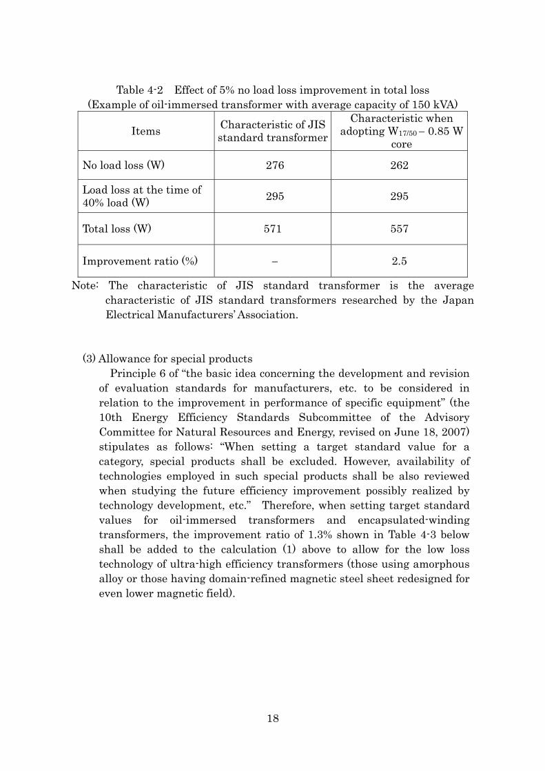
Table 4-2 Effect of 5% no load loss improvement in total loss
(Example of oil-immersed transformer with average capacity of 150 kVA)
Items Characteristic of JIS standard transformer
Characteristic when adopting W17/50 − 0.85 W
core
No load loss (W) 276 262
Load loss at the time of 40% load (W) 295 295
Total loss (W) 571 557
Improvement ratio (%) − 2.5
Note: The characteristic of JIS standard transformer is the average characteristic of JIS standard transformers researched by the Japan Electrical Manufacturers’ Association.
(3) Allowance for special products Principle 6 of “the basic idea concerning the development and revision
of evaluation standards for manufacturers, etc. to be considered in relation to the improvement in performance of specific equipment” (the 10th Energy Efficiency Standards Subcommittee of the Advisory Committee for Natural Resources and Energy, revised on June 18, 2007) stipulates as follows: “When setting a target standard value for a category, special products shall be excluded. However, availability of technologies employed in such special products shall be also reviewed when studying the future efficiency improvement possibly realized by technology development, etc.” Therefore, when setting target standard values for oil-immersed transformers and encapsulated-winding transformers, the improvement ratio of 1.3% shown in Table 4-3 below shall be added to the calculation (1) above to allow for the low loss technology of ultra-high efficiency transformers (those using amorphous alloy or those having domain-refined magnetic steel sheet redesigned for even lower magnetic field).
18
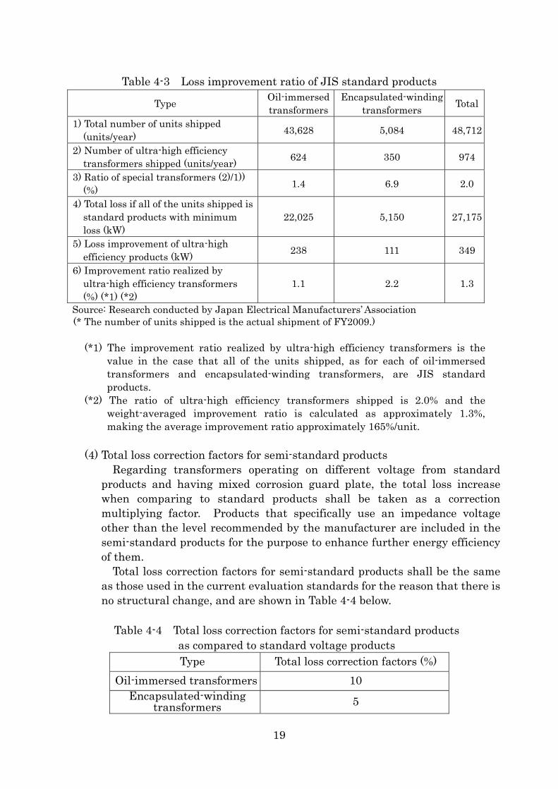
Table 4-3 Loss improvement ratio of JIS standard products
Type Oil-immersed transformers
Encapsulated-winding transformers Total
1) Total number of units shipped (units/year) 43,628 5,084 48,712
2) Number of ultra-high efficiency transformers shipped (units/year) 624 350 974
3) Ratio of special transformers (2)/1)) (%) 1.4 6.9 2.0
4) Total loss if all of the units shipped is standard products with minimum loss (kW)
22,025 5,150 27,175
5) Loss improvement of ultra-high efficiency products (kW) 238 111 349
6) Improvement ratio realized by ultra-high efficiency transformers (%) (*1) (*2)
1.1 2.2 1.3
Source: Research conducted by Japan Electrical Manufacturers’ Association (* The number of units shipped is the actual shipment of FY2009.)
(*1) The improvement ratio realized by ultra-high efficiency transformers is the value in the case that all of the units shipped, as for each of oil-immersed transformers and encapsulated-winding transformers, are JIS standard products.
(*2) The ratio of ultra-high efficiency transformers shipped is 2.0% and the weight-averaged improvement ratio is calculated as approximately 1.3%, making the average improvement ratio approximately 165%/unit.
(4) Total loss correction factors for semi-standard products
Regarding transformers operating on different voltage from standard products and having mixed corrosion guard plate, the total loss increase when comparing to standard products shall be taken as a correction multiplying factor. Products that specifically use an impedance voltage other than the level recommended by the manufacturer are included in the semi-standard products for the purpose to enhance further energy efficiency of them.
Total loss correction factors for semi-standard products shall be the same as those used in the current evaluation standards for the reason that there is no structural change, and are shown in Table 4-4 below.
Table 4-4 Total loss correction factors for semi-standard products
as compared to standard voltage products Type Total loss correction factors (%)
Oil-immersed transformers 10 Encapsulated-winding
transformers 5
19
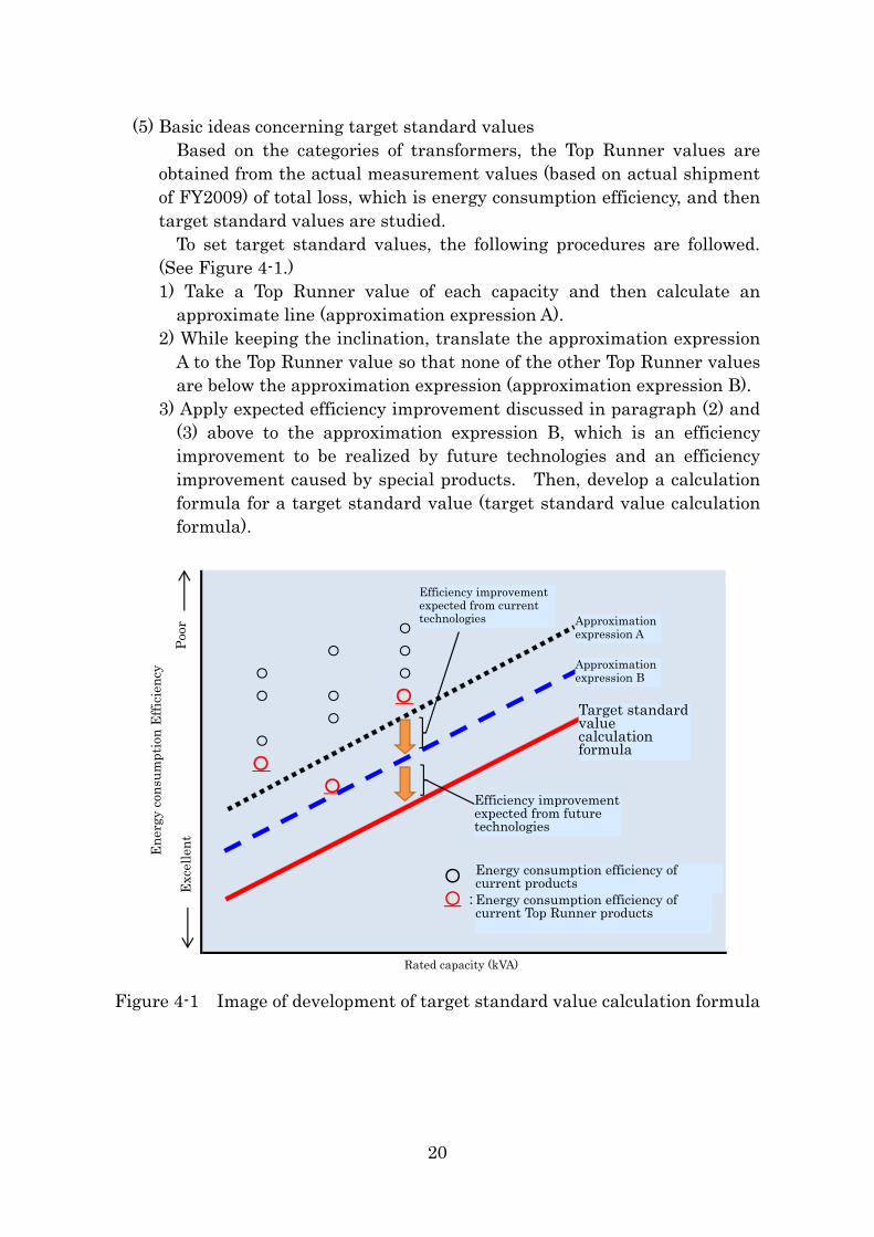
(5) Basic ideas concerning target standard values Based on the categories of transformers, the Top Runner values are
obtained from the actual measurement values (based on actual shipment of FY2009) of total loss, which is energy consumption efficiency, and then target standard values are studied.
To set target standard values, the following procedures are followed. (See Figure 4-1.) 1) Take a Top Runner value of each capacity and then calculate an
approximate line (approximation expression A). 2) While keeping the inclination, translate the approximation expression
A to the Top Runner value so that none of the other Top Runner values are below the approximation expression (approximation expression B).
3) Apply expected efficiency improvement discussed in paragraph (2) and (3) above to the approximation expression B, which is an efficiency improvement to be realized by future technologies and an efficiency improvement caused by special products. Then, develop a calculation formula for a target standard value (target standard value calculation formula).
○ 近似式A
○ ○
○ ○
○ ○
近似式B
○○
○
目標基準値
算定式
○
○
○ 効率: 現行製品のエネルギー消費
○ :
定
現行のトップランナー製品の
エネルギー消費効率
格容量(kVA)
エネルギー
消費効率
現行の技術によ
る効率改善分悪い
良い
将来技術による
効率改善分
Approximation expression B
Target standard value calculation formula
Efficiency improvement expected from future technologies
Energy consumption efficiency of current products Energy consumption efficiency of current Top Runner products
Rated capacity (kVA)
Exc
elle
nt
Ene
rgy
cons
umpt
ion
Effi
cien
cy
Approximation expression A
Efficiency improvement expected from current technologies
Poor
Figure 4-1 Image of development of target standard value calculation formula
20
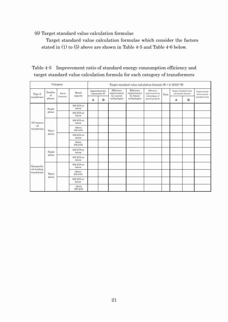
(6) Target standard value calculation formulae Target standard value calculation formulae which consider the factors
stated in (1) to (5) above are shown in Table 4-5 and Table 4-6 below. Table 4-5 Improvement ratio of standard energy consumption efficiency and target standard value calculation formula for each category of transformers
A B A B
50Hz 500kVA以下 11.6 0.732 9.7% 2.5% 1.3% 3.8% 11 .2 0 .732 12.8%
60Hz 5 11.5 0.725 9.0% 2.5% 1.3% 3.8% 11 .1 0 .725 12.2%
5 17.3 0.696 8.5% 2.5% 1.3% 3.8% 16 .6 0 .696 11.7%
50 11.5 0.809 6.6% 2.5% 1.3% 3.8% 11 .1 0 .809 9.9%
5 18.0 0.678 8.0% 2.5% 1.3% 3.8% 17 .3 0 .678 11.6%
50 12.2 0.790 10.5% 2.5% 1.3% 3.8% 11 .7 0 .790 14.2%
50Hz 5 17.6 0.674 10.6% 2.5% 1.3% 3.8% 16 .9 0 .674 14.2%
60Hz 5 15.8 0.691 12.0% 2.5% 1.3% 3.8% 15 .2 0 .691 15.4%
5 24.8 0.659 10.6% 2.5% 1.3% 3.8% 23 .9 0 .659 13.9%
50 23.6 0.718 7.4% 2.5% 1.3% 3.8% 22 .7 0 .718 11.0%
5 23.2 0.674 12.1% 2.5% 1.3% 3.8% 22 .3 0 .674 15.5%
50 20.2 0.737 10.1% 2.5% 1.3% 3.8% 19 .4 0 .737 13.2%
変圧器の
50Hz
60Hz
現
50Hz
60Hz
00kVA以下
00kVA以下
0kVA超過
00kVA以下
0kVA超過
00kVA以下
00kVA以下
00kVA以下
0kVA超過
00kVA以下
0kVA超過
将来技術による効率改
善分
特殊品の技術による効率改善分
現行技術による効率改
善分
区分
種別相数
定格周波数
定格容量近似式B
単相
三相
行基準値からの改善
目標基準値算定式 ( E=A・(kVA)^B )
モールド変圧器
単相
三相
計
目標基準値算定式
油入変圧器
Category Target standard value calculation formula (E = A・(kVA)^B)
Efficiency improvement
by current technologies
Efficiency improvement
by future technologies
Approximation expression B
Efficiency improvement by technologies of
special products
Target standard value calculation formula
Improvement from current
standard value
Number of
phases
Rated capacity
Rated frequency
Type of transformer
Total
500 kVA or below Single
phase 500 kVA or below
500 kVA or below Oil-immers
ed transformer
500 kVA or below
500 kVA or below
500 kVA or below
500 kVA or below
500 kVA or below
Above
Above 500 kVA
Above 500 kVA
500 kVA Three phase
Single phase
Encapsulated-winding transformer Three
phase
Above 500 kVA
21
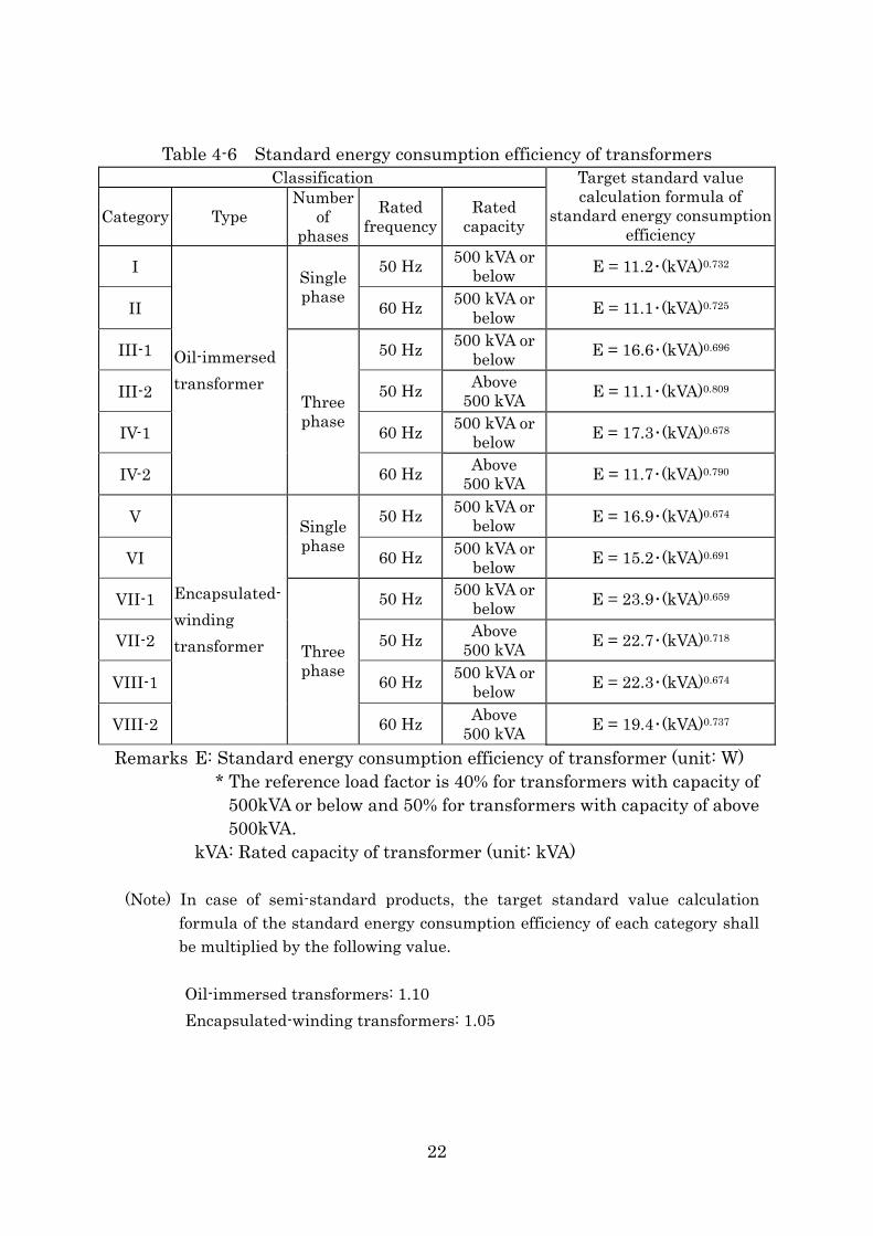
Table 4-6 Standard energy consumption efficiency of transformers
Classification
Category Type Number
of phases
Rated frequency
Rated capacity
Target standard value calculation formula of
standard energy consumption efficiency
I 50 Hz 500 kVA or below E = 11.2・(kVA)0.732
II
Single phase 60 Hz 500 kVA or
below E = 11.1・(kVA)0.725
III-1 50 Hz 500 kVA or below E = 16.6・(kVA)0.696
III-2 50 Hz Above 500 kVA E = 11.1・(kVA)0.809
IV-1 60 Hz 500 kVA or below E = 17.3・(kVA)0.678
IV-2
Oil-immersed transformer
Three phase
60 Hz Above 500 kVA E = 11.7・(kVA)0.790
V 50 Hz 500 kVA or below E = 16.9・(kVA)0.674
VI
Single phase
60 Hz 500 kVA or below E = 15.2・(kVA)0.691
VII-1 50 Hz 500 kVA or below E = 23.9・(kVA)0.659
VII-2 50 Hz Above 500 kVA E = 22.7・(kVA)0.718
VIII-1 60 Hz 500 kVA or below E = 22.3・(kVA)0.674
VIII-2
Encapsulated-winding transformer Three
phase
60 Hz Above 500 kVA E = 19.4・(kVA)0.737
Remarks E: Standard energy consumption efficiency of transformer (unit: W) * The reference load factor is 40% for transformers with capacity of
500kVA or below and 50% for transformers with capacity of above 500kVA.
kVA: Rated capacity of transformer (unit: kVA)
(Note) In case of semi-standard products, the target standard value calculation formula of the standard energy consumption efficiency of each category shall be multiplied by the following value.
Oil-immersed transformers: 1.10 Encapsulated-winding transformers: 1.05
22
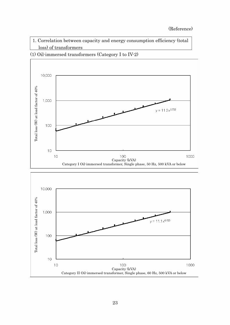
(Reference)
1. Correlation between capacity and energy consumption efficiency (total loss) of transformers
(1) Oil-immersed transformers (Category I to IV-2)
Tota
l los
s (W
) at l
oad
fact
or o
f 40%
Capacity (kVA)Category II Oil-immersed transformer, Single phase, 60 Hz, 500 kVA or below
Tota
l los
s (W
) at l
oad
fact
or o
f 40%
Capacity (kVA)Category I Oil-immersed transformer, Single phase, 50 Hz, 500 kVA or below
23
区分Ⅲ-1 油入変圧器 三相・50Hz・500kVA以下
y = 16.6x0.696
10
100
1,000
10,000
10 100 1000
量(kVA)
負荷
率40%時
の損
失(W
)
容
Tota
l los
s (W
) at l
oad
fact
or o
f 40%
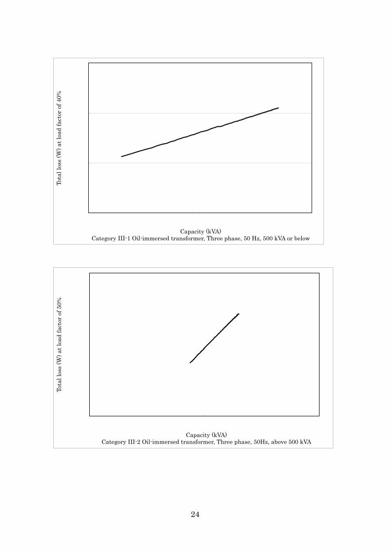
Capacity (kVA)Category III-1 Oil-immersed transformer, Three phase, 50 Hz, 500 kVA or below
y = 11.1x0.809
1,000
10,000
100 1000 10000
負荷
率50%時
の全
損失
(W)
区分Ⅲ-2 油入変圧器 三相・50Hz・500kVA超過容量(kVA)
Tota
l los
s (W
) at l
oad
fact
or o
f 50%
Capacity (kVA)Category III-2 Oil-immersed transformer, Three phase, 50Hz, above 500 kVA
24
y = 11.7 x0.790
1,000
10,000
100 1000 10000
負荷
率50%時
の全
損失
(W)
容量(kVA)区分Ⅳ-2 油入変圧器 三相・60Hz・500kVA超過
Capacity (kVA)Category IV-1 Oil-immersed transformer, Three phase, 60 Hz, 500 kVA or below
Tota
l los
s (W
) at l
oad
fact
or o
f 40%
Capacity (kVA)Category IV-2 Oil-immersed transformer, Three phase, 60 Hz, above 500 kVA
Tota
l los
s (W
) at l
oad
fact
or o
f 50%
25
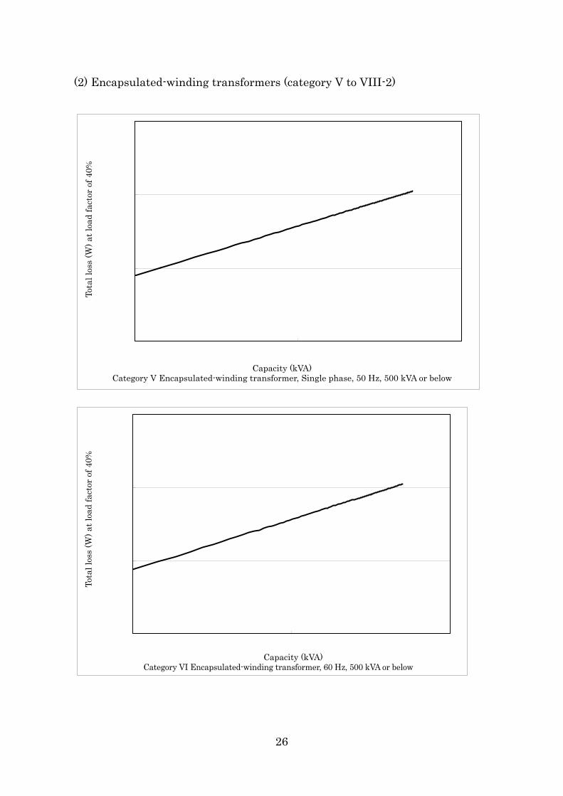
(2) Encapsulated-winding transformers (category V to VIII-2)
y = 16.9x0.674
10
100
1,000
10,000
10 100 1000
負荷
率40%時
の全
損失
(W)
区分Ⅴ モールド変圧器 単相・50Hz・500kVA以下
)容量(kVACapacity (kVA)Category V Encapsulated-winding transformer, Single phase, 50 Hz, 500 kVA or below
Tota
l los
s (W
) at l
oad
fact
or o
f 40%
y = 15.2x0.691
10
100
1,000
10,000
10 100 1000
負荷
率40%時
の損
失(W
)
容量(kVA) 区分Ⅵ 受配電用変圧器(モールド変圧器・60Hz・500kVA以下)
Capacity (kVA)Category VI Encapsulated-winding transformer, 60 Hz, 500 kVA or below
Tota
l los
s (W
) at l
oad
fact
or o
f 40%
26
区分Ⅶ-1 モールド変圧器 三相・50Hz・500kVA以下
y = 23.9x0.659
100
1,000
10,000
10 100 1000
kVA)
負荷
率40%時
の全
損失
(W)
容量(Capacity (kVA)Category VII-1 Encapsulated-winding transformer, Three phase, 50 Hz, 500 kVA or below
Tota
l los
s (W
) at l
oad
fact
or o
f 40%
y = 22.7x0.718
1,000
10,000
100 1000 10000
負荷
率50%時
の全
損失
(W)
区分Ⅶ-2 モールド変圧器 三相・50Hz・500kVA超過A)容量(kVCapacity (kVA)
Category VII-2 Encapsulated-winding transformer, Three phase, 50 Hz, above 500 kVA
Tota
l los
s (W
) at l
oad
fact
or o
f 50%
27
区分Ⅷ-1 モールド変圧器 三相・60Hz・500kVA以下
y = 22.3x0.674
100
1,000
10,000
10 100 1000
kVA)
負荷
率40%時
の全
損失
(W)
容量(Capacity (kVA)Category VIII-1 Encapsulated-winding transformer, Three phase, 60 Hz, 500 kVA or below
Tota
l los
s (W
) at l
oad
fact
or o
f 40%
区分Ⅷ-2 受配電用変圧器(モールド変圧器・60Hz・500kVA超過)
y = 19.4x0.737
1,000
10,000
100 1000 10000
負荷
率50%時
の損
失(W
)
容量(kVA) Capacity (kVA)Category VIII-2 Encapsulated-winding transformer, 60 Hz, above 500 kVA
Tota
l los
s (W
) at l
oad
fact
or o
f 50%
28
Attachment 5
Energy Consumption Efficiency of Power Transformers
and its Measurement Method 1. Basic ideas Transformers have been designated as specified equipment since FY2002,
and total loss (W) prescribed in JIS C4304 “6kV Oil-immersed distribution transformers” and JIS C4306 “6kV Encapsulated-winding distribution transformers” has been adopted to be used for the evaluation of energy consumption efficiency and its measurement method.
When studying new standards, it is deemed reasonable to continue to use it as a practical index to evaluate energy consumption efficiency of transformers.
2. Specific energy consumption efficiency and its measurement method (1) Energy consumption efficiency
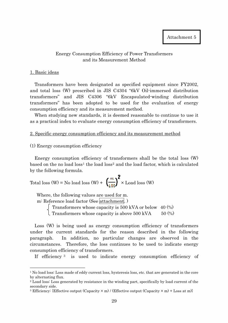
Energy consumption efficiency of transformers shall be the total loss (W) based on the no load loss1 the load loss2 and the load factor, which is calculated by the following formula. Total loss (W) = No load loss (W) + × Load loss (W)
Where, the following values are used for m. m: Reference load factor (See attachment. )
Transformers whose capacity is 500 kVA or below 40 (%) Transformers whose capacity is above 500 kVA 50 (%)
Loss (W) is being used as energy consumption efficiency of transformers
under the current standards for the reason described in the following paragraph. In addition, no particular changes are observed in the circumstances. Therefore, the loss continues to be used to indicate energy consumption efficiency of transformers.
If efficiency 3 is used to indicate energy consumption efficiency of
1 No load loss: Loss made of eddy current loss, hysteresis loss, etc. that are generated in the core by alternating flux. 2 Load loss: Loss generated by resistance in the winding part, specifically by load current of the secondary side. 3 Efficiency: {Effective output (Capacity × m) / (Effective output (Capacity × m) + Loss at m)}
29
transformers, the loss will become extremely small against the effective output and the energy saving turns out to be a value under the decimal point. In this case, when calculating the amount of energy to be saved, it needs to be converted to loss, making its handling inconvenient. Therefore, loss is used to indicate energy consumption efficiency because being an absolute value makes it easy to handle and because it can be expressed by the unit of W (watt) allowing easier application to other purposes such as calculation of effect, etc. By the way, loss used here as energy consumption efficiency is the loss generated when a transformer operating at prescribed load factor. (2) Measuring method of energy consumption efficiency
Measuring method of no load loss and load loss shall be in accordance with “9.2 Measurement of Winding Resistance”, “9.3 No load Current and No Load Loss Testing”, and “9.5 Load Loss and Short-circuit Impedance Testing” stipulated by JIS C 4304 “6kV Oil-immersed distribution transformers” and JIS C 4306 “6kV Encapsulated-winding distribution transformers”.
30
Attachment
Reference Load Factor
When setting a reference load factor, considering the fact that load loss greatly changes (3 to 8 times greater than the case of no-load loss) depending on a reference load factor used, it is necessary to pay attention to that 1) it is a value based on actual use and 2) sufficient energy saving effect can be achieved even if the load factor actually used changes. From these points of view, study is made to set reasonable reference load factor. 1. Type of rated capacity based on JIS
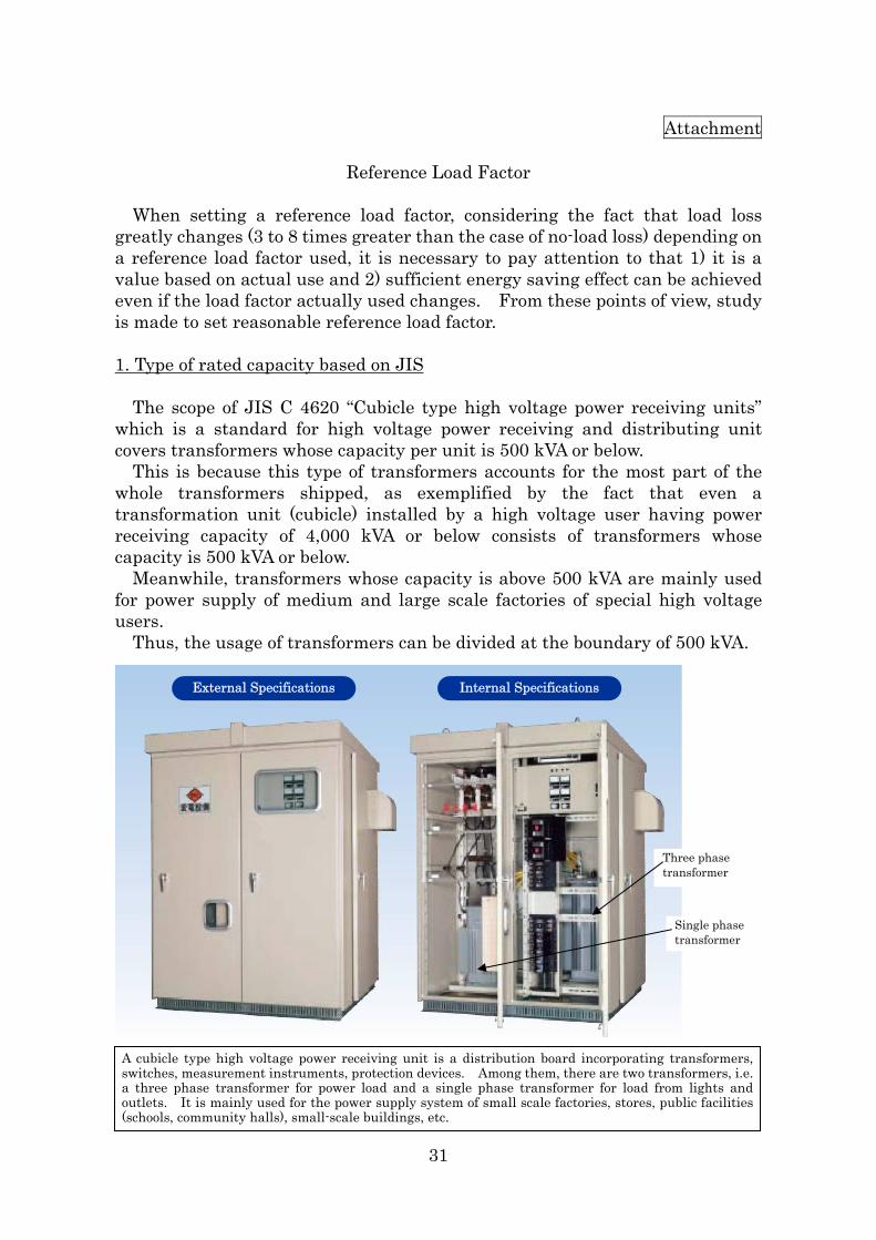
The scope of JIS C 4620 “Cubicle type high voltage power receiving units” which is a standard for high voltage power receiving and distributing unit covers transformers whose capacity per unit is 500 kVA or below.
This is because this type of transformers accounts for the most part of the whole transformers shipped, as exemplified by the fact that even a transformation unit (cubicle) installed by a high voltage user having power receiving capacity of 4,000 kVA or below consists of transformers whose capacity is 500 kVA or below.
Meanwhile, transformers whose capacity is above 500 kVA are mainly used for power supply of medium and large scale factories of special high voltage users. hus, the usage of transformers can be divided at the boundary of 500 kVA. T
External Specifications Internal Specifications
Three phase transformer
Single phase transformer
A cubicle type high voltage power receiving unit is a distribution board incorporating transformers, switches, measurement instruments, protection devices. Among them, there are two transformers, i.e. a three phase transformer for power load and a single phase transformer for load from lights and outlets. It is mainly used for the power supply system of small scale factories, stores, public facilities (schools, community halls), small-scale buildings, etc.
31
2. Selection of reference load factor (1) Research results of reference load factor
According to the survey of user companies on annual load factor conducted by the Japan Electrical Manufacturers’ Association and Japan Switchboard and Control System Industries Association in FY2010, the annual load factor is 36.4% in daytime, 9.7% at nighttime and 26.6% in average for transformers of 500 kVA or below, and the annual load factor is 47.1% in daytime, 29.6% at nighttime and 39.3% in average for transformers of above 500 kVA.
However, this result needs to consider the correction of power factor made by a phase advanced capacitor.
In power receiving units, the load power factor on the secondary side of a transformer is normally from 0.80 to 0.85 and the actual load factor of a transformer is higher than that of the high voltage receiving end. Generally, a phase advanced capacitor is used on high-voltage receiving ends with the aim of achieving a power factor of 0.95, and thus the actual load factor of transformers is higher by 12% to 19%.
Based on this, the actual load factor is estimated to be approximately 11% to 42% for transformers of 500 kVA or below and approximately 34% to 54% for transformers of above 500 kVA. (2) Adequacy of reference load factor According to the research said in the foregoing paragraph (1), the average load factor by user’s application shifted as shown in Table 1 below.
Table 1 Comparison of average load factor by user’s application FY2001 FY2010
Factories 40.8% 31.4% Buildings 19.7% 29.4%
Public facilities 21.0% 40.8%
Load factor by user’s application varies greatly and there is no consistency in the change of load factor.
In other words, when determining a certain reference load factor, while considering the actual load factor, it is necessary to pay attention to the energy saving effect regardless of how it is used (changes of the load factor).
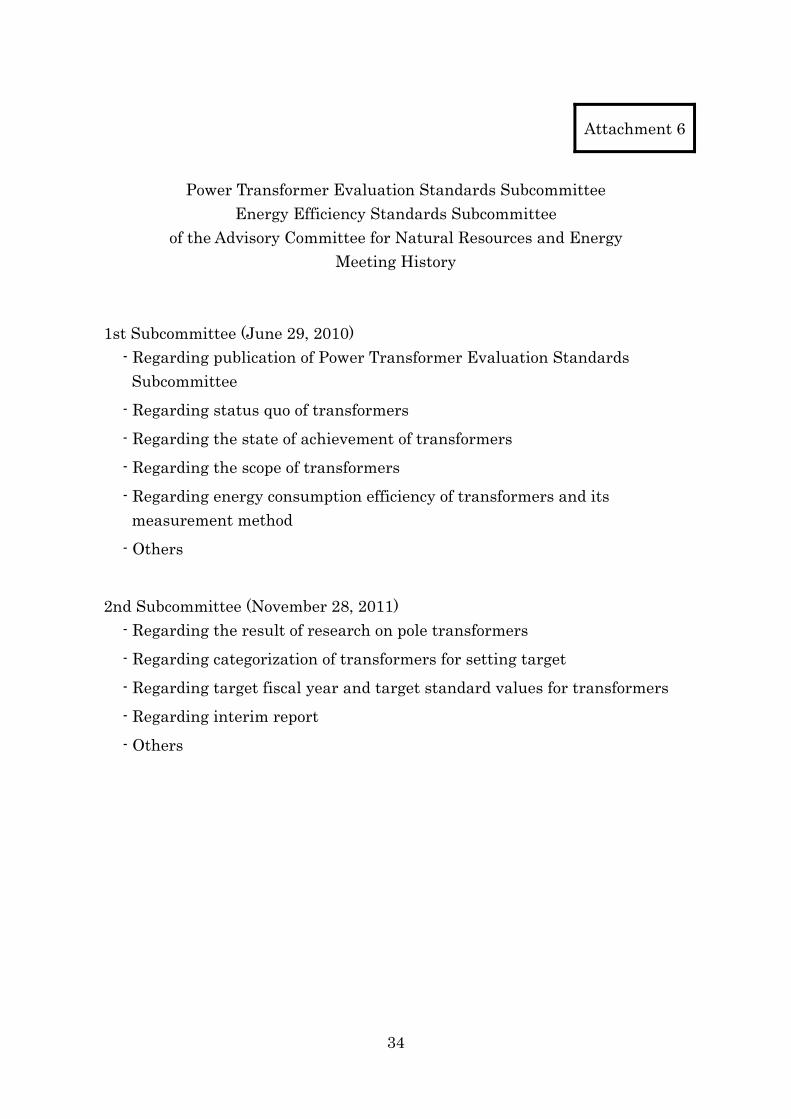
Figure 1 shows the values of total loss of a normal three-phase 200 kVA transformer (current average) whose efficiency was already improved by 20%, when it is designed to achieve the highest efficiency at the reference load factor of 20%, 30%, 40% 50% and 60% respectively. Figure 2 shows these values in index numbers while taking the current average as 1. As Figure 2 shows, the efficiency of the transformer improved in a way that achieves the highest efficiency at the reference load factor of 40% is better than that of the current product in the whole area, indicating that an effective energy saving standard can be set by selecting an intermediate value of the reference load factors. If an extreme load factor is used, to the contrary, it may deviate from practical use
32
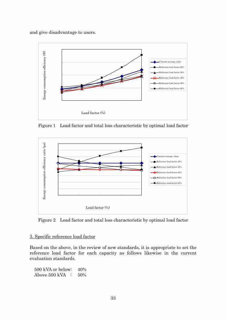
and give disadvantage to users.
0
500
1000
1500
2000
20% 30% 40% 50% 60%
エネ
ルギ
ー消
費効
率(W
)
負荷率(%)
現行平均値
基準負荷率20%
基準負荷率30%
基準負荷率40%
基準負荷率50%
基準負荷率60%
Ene
rgy
cons
umpt
ion
effic
ienc
y (W
)
Reference load factor 60%
Reference load factor 40%
Reference load factor 50%
Reference load factor 30%
Current average value
Reference load factor 20%
Load factor (%)
Figure 1 Load factor and total loss characteristic by optimal load factor
0
0.2
0.4
0.6
0.8
1
1.2
1.4
1.6
20% 30% 40% 50% 60%
負荷率(%)
エネ
ルキ
゙ー消
費効
率比
(pu)
現行平均値
基準負荷率20%
基準負荷率30%
基準負荷率40%
基準負荷率50%
基準負荷率60%
Ene
rgy
cons
umpt
ion
effic
ienc
y ra
tio (p
u)
Load factor (%)
Reference load factor 60%
Reference load factor 50%
Reference load factor 40%
Reference load factor 20%
Reference load factor 30%
Current average value
Figure 2 Load factor and total loss characteristic by optimal load factor
3. Specific reference load factor Based on the above, in the review of new standards, it is appropriate to set the reference load factor for each capacity as follows likewise in the current evaluation standards.
500 kVA or below: 40% Above 500 kVA : 50%
33
Attachment 6
Power Transformer Evaluation Standards Subcommittee
Energy Efficiency Standards Subcommittee of the Advisory Committee for Natural Resources and Energy
Meeting History 1st Subcommittee (June 29, 2010)
- Regarding publication of Power Transformer Evaluation Standards Subcommittee
- Regarding status quo of transformers
- Regarding the state of achievement of transformers
- Regarding the scope of transformers
- Regarding energy consumption efficiency of transformers and its measurement method
- Others
2nd Subcommittee (November 28, 2011) - Regarding the result of research on pole transformers
- Regarding categorization of transformers for setting target
- Regarding target fiscal year and target standard values for transformers
- Regarding interim report
- Others
34
Attachment 7
Power Transformer Evaluation Standards Subcommittee
Energy Efficiency Standards Subcommittee of the Advisory Committee for Natural Resources and Energy
List of Members
Chairman Ryuichi Yokoyama Professor, Graduate School of Environment and Energy
Engineering, Faculty of Science and Engineering, Waseda University
Members Kenji Ishiwatari Japan Switchboard & Control System Industries Association (Manager, Power Distribution Board Designing Section, Osaki Electric Systems Co., Ltd.)
Tatsuki Okamoto Chief Researcher, Electric Power Engineering Research Laboratory, Central Research Institute of Electric Power Industry
Akio Tanaka Manager, Planning and Research Office, Jyukankyo Research Institute Inc. (Replaced by Mr. Tsurusaki below from the second meeting)
Keidai Tsurusaki Chief Researcher, Jyukankyo Research Institute Inc. (from the second meeting)
Yoichi Hanji General Manager, Energy Conservation Technology Division, the Energy Conservation Center, Japan
Yoichi Hori Professor, Graduate School of Frontier Sciences, The University of Tokyo
Hiroshi Matsuzaki Japan Electrical Construction Association (Manager, Engineering Control Section, Facility Engineering Department, Yurtec Co., Inc.)
Yoshio Mochizuki Chief, Transformer and Specified Equipment Evaluation Standard WG, the Japan Electrical Manufacturers’ Association (Adviser in charge of development and designing of stationary equipment, Toshiba Corporation)
Koichi Yasuoka Professor, Graduate School of Science, Tokyo Institute of Technology
Hiroshi Yoshimiya Chief Engineer and Senior Expert, Administration Division, Nikken Sekkei Ltd.
Yuichi Watabe Institute of Electrical Installation Engineers of Japan (Leader, Facility Design Supervising Group, Kajima Corporation)
(In Japanese alphabetical order)
35
Reference 1
Status Quo of Power Transformers I. Types and Classification 1. Utilization of transformers
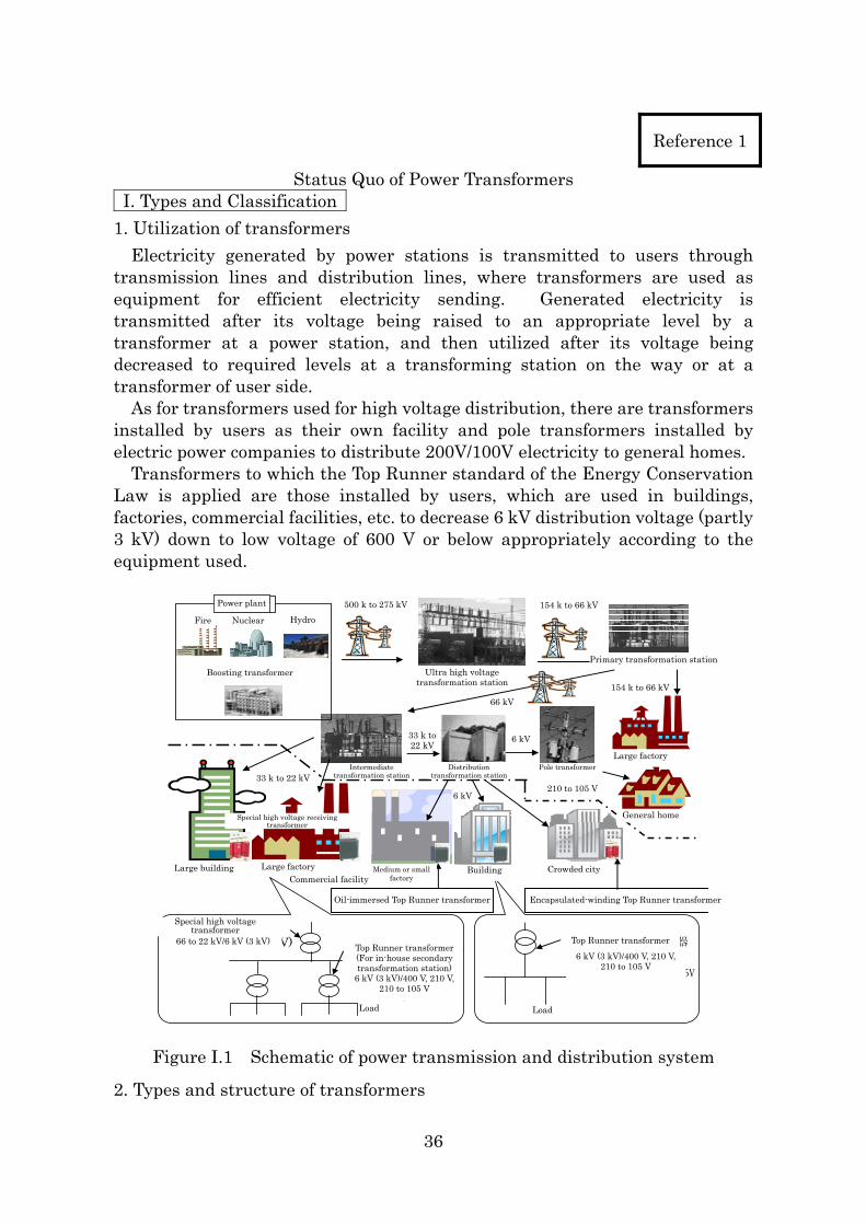
Electricity generated by power stations is transmitted to users through transmission lines and distribution lines, where transformers are used as equipment for efficient electricity sending. Generated electricity is transmitted after its voltage being raised to an appropriate level by a transformer at a power station, and then utilized after its voltage being decreased to required levels at a transforming station on the way or at a transformer of user side.
As for transformers used for high voltage distribution, there are transformers installed by users as their own facility and pole transformers installed by electric power companies to distribute 200V/100V electricity to general homes. Transformers to which the Top Runner standard of the Energy Conservation Law is applied are those installed by users, which are used in buildings, factories, commercial facilities, etc. to decrease 6 kV distribution voltage (partly 3 kV) down to low voltage of 600 V or below appropriately according to the equipment used.
火力 原子力 水力
発
グ
電所用昇圧変圧器
大ビルディン
500k~275kV
超高圧変電所一次変電所
6kV
配電用変電所
大工場 中 場小工 ビル ディング 過密都市
一般住宅
大工場
中間変電所33k~22kV
発電所 154k~66kV
154k~66kV 66kV
33k~
22kV
柱上変圧器
210~105V6kV
特 別高圧受電用変圧器
業務用施設
特
Vト
(
-105V
別高圧変圧器 66~22kV/ 6kV (3k )
ップランナー変圧器
所内二次変電所用)
6kV(3kV)/400V,
210V, 210負荷 負荷
器
0-105V
トップランナー変圧
6kV(3kV)/400V,
210V,21
モールドトップランナー変圧器 油入トップランナー変圧器
Fire
Power plant
Nuclear Hydro
Boosting transformer
500 k to 275 kV
Ultra high voltage transformation station
154 k to 66 kV
66 kV154 k to 66 kV
33 k to 22 kV
6 kV
33 k to 22 kV Intermediate
transformation station
210 to 105 V6 kV
Large factory Pole transformerDistribution
transformation station
Primary transformation station
General home Special high voltage receiving transformer
Large factory Medium or small factory Commercial facility
BuildingLarge building Crowded city
Oil-immersed Top Runner transformer Encapsulated-winding Top Runner transformer
Special high voltage transformer
66 to 22 kV/6 kV (3 kV) Top Runner transformer
Load
Top Runner transformer(For in-house secondary transformation station)
6 kV (3 kV)/400 V, 210 V, 210 to 105 V
6 kV (3 kV)/400 V, 210 V, 210 to 105 V
Load
Figure I.1 Schematic of power transmission and distribution system
2. Types and structure of transformers
36
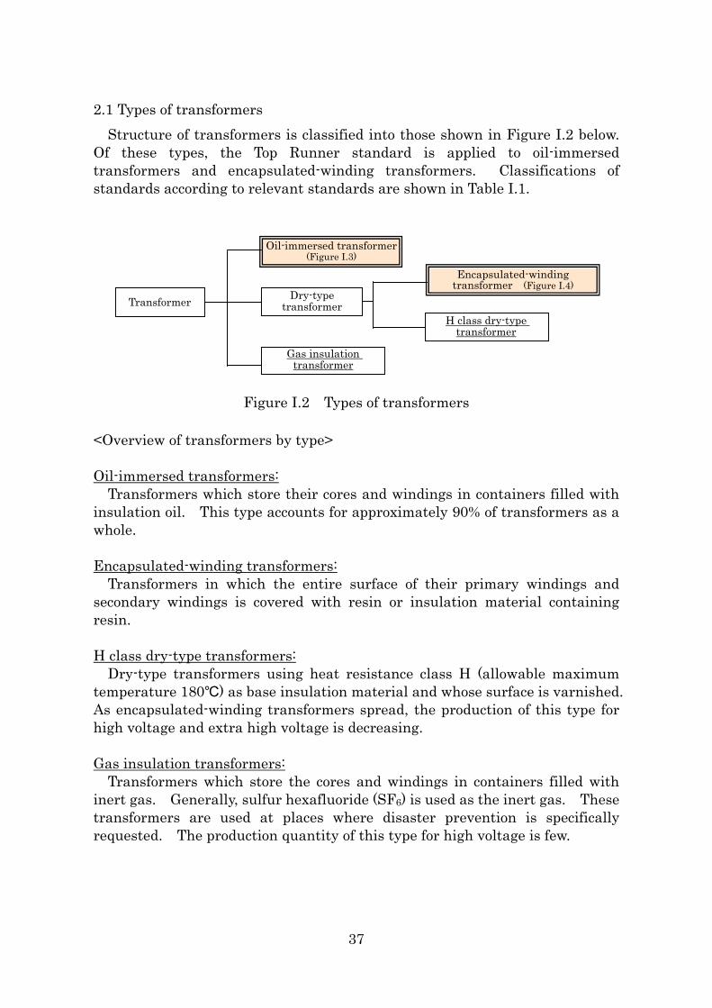
2.1 Types of transformers Structure of transformers is classified into those shown in Figure I.2 below.
Of these types, the Top Runner standard is applied to oil-immersed transformers and encapsulated-winding transformers. Classifications of standards according to relevant standards are shown in Table I.1.
油入変圧器(図Ⅰ.3)
変圧器 乾式変圧器 モールド変圧器 (図Ⅰ.4)
H種乾式変圧器
ガス絶縁変圧器
Oil-immersed transformer (Figure I.3)
Encapsulated-winding transformer (Figure I.4)
Dry-type transformer Transformer
H class dry-type transformer
Gas insulation transformer
Figure I.2 Types of transformers
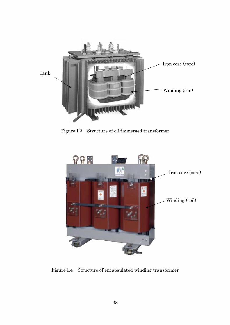
<Overview of transformers by type> Oil-immersed transformers:
Transformers which store their cores and windings in containers filled with insulation oil. This type accounts for approximately 90% of transformers as a whole. Encapsulated-winding transformers:
Transformers in which the entire surface of their primary windings and secondary windings is covered with resin or insulation material containing resin. H class dry-type transformers:
Dry-type transformers using heat resistance class H (allowable maximum temperature 180℃) as base insulation material and whose surface is varnished. As encapsulated-winding transformers spread, the production of this type for high voltage and extra high voltage is decreasing.
Gas insulation transformers:
Transformers which store the cores and windings in containers filled with inert gas. Generally, sulfur hexafluoride (SF6) is used as the inert gas. These transformers are used at places where disaster prevention is specifically requested. The production quantity of this type for high voltage is few.
37
Iron core (core)
Winding (coil)
Tank
Figure I.3 Structure of oil-immersed transformer
Iron core (core)
Winding (coil)
Figure I.4 Structure of encapsulated-winding transformer
38
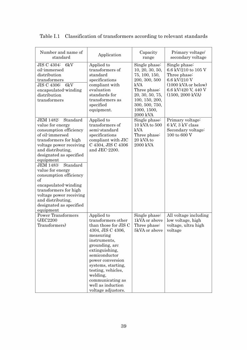
Table I.1 Classification of transformers according to relevant standards
Number and name of standard Application Capacity
range Primary voltage/ secondary voltage
JIS C 4304: 6kV oil-immersed distribution transformers JIS C 4306: 6kV encapsulated-winding distribution transformers
Applied to transformers of standard specifications compliant with evaluation standards for transformers as specified equipment.
Single phase: 10, 20, 30, 50, 75, 100, 150, 200, 300, 500 kVA Three phase: 20, 30, 50, 75, 100, 150, 200, 300, 500, 750, 1000, 1500, 2000 kVA
Single phase: 6.6 kV/210 to 105 V Three phase: 6.6 kV/210 V (1000 kVA or below) 6.6 kV/420 V, 440 V (1500, 2000 kVA)
JEM 1482: Standard value for energy consumption efficiency of oil-immersed transformers for high voltage power receiving and distributing, designated as specified equipment JEM 1483: Standard value for energy consumption efficiency of encapsulated-winding transformers for high voltage power receiving and distributing, designated as specified equipment
Applied to transformers of semi-standard specifications compliant with JIC C 4304, JIS C 4306 and JEC-2200.
Single phase: 10 kVA to 500 kVA Three phase: 20 kVA to 2000 kVA
Primary voltage: 6 kV, 3 kV class Secondary voltage: 100 to 600 V
Power Transformers (JEC2200 Transformers)
Applied to transformers other than those for JIS C 4304, JIS C 4306, measuring instruments, grounding, arc extinguishing, semiconductor power conversion systems, starting, testing, vehicles, welding, communicating as well as induction voltage adjustors.
Single phase: 1kVA or aboveThree phase: 5kVA or above
All voltage including low voltage, high voltage, ultra high voltage
39
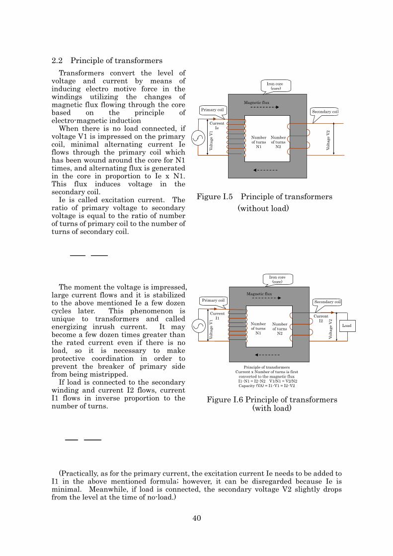
2.2 Principle of transformers Transformers convert the level of voltage and current by means of inducing electro motive force in the windings utilizing the changes of magnetic flux flowing through the core based on the principle of electro-magnetic induction When there is no load connected, if voltage V1 is impressed on the primary coil, minimal alternating current Ie flows through the primary coil which has been wound around the core for N1 times, and alternating flux is generated in the core in proportion to Ie x N1. This flux induces voltage in the secondary coil.
鉄心(コア)
Ie is called excitation current. The ratio of primary voltage to secondary voltage is equal to the ratio of number of turns of primary coil to the number of turns of secondary coil.
The moment the voltage is impressed,
large current flows and it is stabilized to the above mentioned Ie a few dozen cycles later. This phenomenon is unique to transformers and called energizing inrush current. It may become a few dozen times greater than the rated current even if there is no load, so it is necessary to make protective coordination in order to prevent the breaker of primary side from being mistripped. If load is connected to the secondary winding and current I2 flows, current I1 flows in inverse proportion to the number of turns.
(Practically, as for the primary current, the excitation current Ie needs to be added to
I1 in the above mentioned formula; however, it can be disregarded because Ie is minimal. Meanwhile, if load is connected, the secondary voltage V2 slightly drops from the level at the time of no-load.)
鉄心(コア)
束
二次コイル一次コイル
電流I1電流I2
ターン数N1
トランスの原理電流×巻回数を一旦磁束に変換I1・N1=I2・N2 V1/N1=V2/N2
容量(VA)=I1・V1=I2・V2
ターン数N2電
圧V
1
電圧
V2
負荷
Figure I.6 Principle of transformers (with load)
E2
E1=
N2
N1 ・・・・・・・・・・・・・・・・・(1
I2
I1=
N1
N2 ・・・・・・・・・・・・・・・・・(2
磁束
一次コイル 二次コイル
電流Ie
タN
ーン数
1ターン数
N2電圧
V1
電圧
V2
Figure I.5 Principle of transformers (without load)
Iron core (core)
Volta
ge V
2
Volta
ge V
1
Current Ie
Magnetic flux
Primary coil
Number of turns
N1
Number of turns
N2
Iron core (core)
Volta
ge V
2
Current I1
Number of turns
N1
Number of turns
N2
Current I2
Secondary coil
Volta
ge V
1
Magnetic flux
Secondary coilPrimary coil
Load
Principle of transformers Current x Number of turns is first
converted to the magnetic flux I1・N1 = I2・N2 V1/N1 = V2/N2
Capacity (VA) = I1・V1 = I2・V2
40
From formulae (1) and (2) above, the following relational formula (3) is introduced.
Voltage × Current of the primary and secondary are almost equal.
V1×I1=V2×I2 ・・・・・・・・・・・(3)
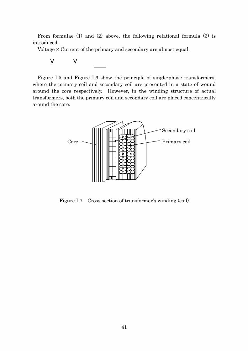
Figure I.5 and Figure I.6 show the principle of single-phase transformers, where the primary coil and secondary coil are presented in a state of wound around the core respectively. However, in the winding structure of actual transformers, both the primary coil and secondary coil are placed concentrically around the core.
Primary coil
Secondary coil
Core
Figure I.7 Cross section of transformer’s winding (coil)
41
2.3 Causes for generation of loss and improvement measures There is resistance in the windings in actual use and loss is generated if
current flows there. This is generated depending on the amount of load current in the secondary side and called load loss.
Meanwhile, eddy current loss and hysteresis loss are generated in the core when alternating flux flows. These losses have nothing to do with the amount of load and are called no load loss.
A transformer is stationary equipment consisting of cores where magnetic flux flows and windings where current flows. Energy efficiency of transformers has been improved so far by advancing the technologies for windings and cores.
Main technologies for reducing loss are as follows. (1) Reduction of no load loss
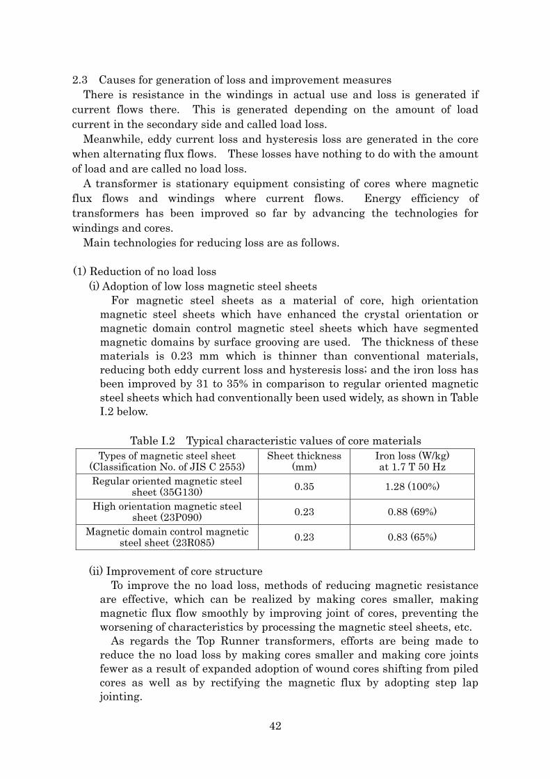
(i) Adoption of low loss magnetic steel sheets For magnetic steel sheets as a material of core, high orientation
magnetic steel sheets which have enhanced the crystal orientation or magnetic domain control magnetic steel sheets which have segmented magnetic domains by surface grooving are used. The thickness of these materials is 0.23 mm which is thinner than conventional materials, reducing both eddy current loss and hysteresis loss; and the iron loss has been improved by 31 to 35% in comparison to regular oriented magnetic steel sheets which had conventionally been used widely, as shown in Table I.2 below.
Table I.2 Typical characteristic values of core materials
Types of magnetic steel sheet (Classification No. of JIS C 2553)
Sheet thickness (mm)
Iron loss (W/kg) at 1.7 T 50 Hz
Regular oriented magnetic steel sheet (35G130) 0.35 1.28 (100%)
High orientation magnetic steel sheet (23P090) 0.23 0.88 (69%)
Magnetic domain control magnetic steel sheet (23R085) 0.23 0.83 (65%)
(ii) Improvement of core structure
To improve the no load loss, methods of reducing magnetic resistance are effective, which can be realized by making cores smaller, making magnetic flux flow smoothly by improving joint of cores, preventing the worsening of characteristics by processing the magnetic steel sheets, etc.
As regards the Top Runner transformers, efforts are being made to reduce the no load loss by making cores smaller and making core joints fewer as a result of expanded adoption of wound cores shifting from piled cores as well as by rectifying the magnetic flux by adopting step lap jointing.
42
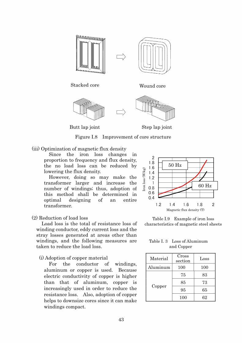
Stacked core Wound core
Figure I.8 Improvement of core structure
Butt lap joint Step lap joint
(iii) Optimization of magnetic flux density
Since the iron loss changes in proportion to frequency and flux density, the no load loss can be reduced by lowering the flux density. However, doing so may make the transformer larger and increase the number of windings; thus, adoption of this method shall be determined in optimal designing of an entire transformer.
(2) Reduction of load loss
Load loss is the total of resistance loss of winding conductor, eddy current loss and the stray losses generated at areas other than windings, and the following measures are taken to reduce the load loss. (i) Adoption of copper material
For the conductor of windings, aluminum or copper is used. Because electric conductivity of copper is higher than that of aluminum, copper is increasingly used in order to reduce the resistance loss. Also, adoption of copper helps to downsize cores since it can make windings compact.
Table I. 3 Loss of Aluminum and Copper
Material Cross section Loss
Aluminum 100 100 75 83 85 73 95 65
Copper
100 62
Figure I.9 Example of iron loss of magnetic steel sheet
50 Hz
60 Hz
Magnetic flux density (T)
Iron
loss
(W/k
g)
Table I.9 Example of iron loss characteristics of magnetic steel sheets
43
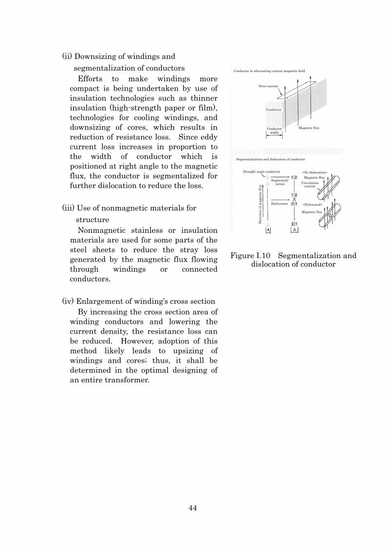
(ii) Downsizing of windings and segmentalization of conductors Efforts to make windings more
compact is being undertaken by use of insulation technologies such as thinner insulation (high-strength paper or film), technologies for cooling windings, and downsizing of cores, which results in reduction of resistance loss. Since eddy current loss increases in proportion to the width of conductor which is positioned at right angle to the magnetic flux, the conductor is segmentalized for further dislocation to reduce the loss.
(iii) Use of nonmagnetic materials for
structure Nonmagnetic stainless or insulation
materials are used for some parts of the steel sheets to reduce the stray loss generated by the magnetic flux flowing through windings or connected conductors.
Magnetic flux
<Dislocated>
Circulation current
Magnetic flux<No dislocation>Straight angle conductor
Dir
ectio
n of
mag
netic
flux
Dislocation
Segmentali- zation
Segmentalization and dislocation of conductor
Conductor width
Magnetic flux
Conductor
Over current
Conductor in alternating current magnetic field
Figure I.10 Segmentalization and dislocation of conductor
(iv) Enlargement of winding’s cross section
By increasing the cross section area of winding conductors and lowering the current density, the resistance loss can be reduced. However, adoption of this method likely leads to upsizing of windings and cores; thus, it shall be determined in the optimal designing of an entire transformer.
44
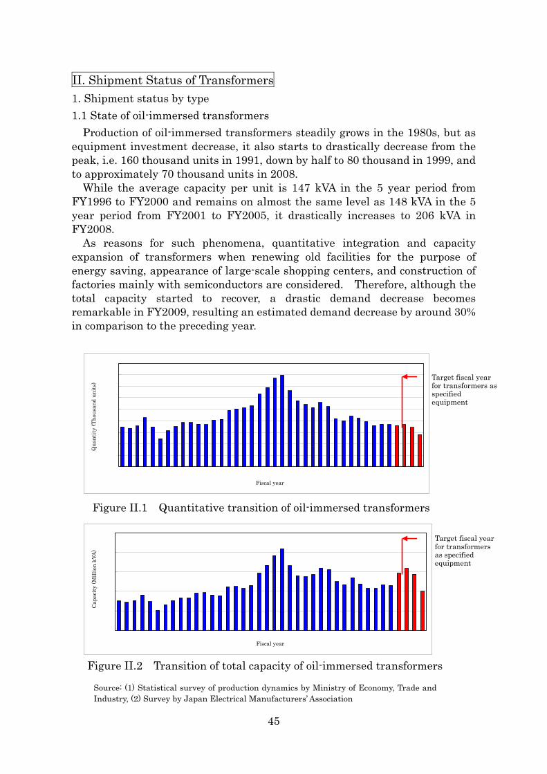
II. Shipment Status of Transformers 1. Shipment status by type 1.1 State of oil-immersed transformers
Production of oil-immersed transformers steadily grows in the 1980s, but as equipment investment decrease, it also starts to drastically decrease from the peak, i.e. 160 thousand units in 1991, down by half to 80 thousand in 1999, and to approximately 70 thousand units in 2008.
While the average capacity per unit is 147 kVA in the 5 year period from FY1996 to FY2000 and remains on almost the same level as 148 kVA in the 5 year period from FY2001 to FY2005, it drastically increases to 206 kVA in FY2008.
As reasons for such phenomena, quantitative integration and capacity expansion of transformers when renewing old facilities for the purpose of energy saving, appearance of large-scale shopping centers, and construction of factories mainly with semiconductors are considered. Therefore, although the total capacity started to recover, a drastic demand decrease becomes remarkable in FY2009, resulting an estimated demand decrease by around 30% in comparison to the preceding year.
0
20
40
60
80
100
120
140
160
180
1970 72 74 76 78 1980 82 84 86 88 1990 92 94 96 98 2000 02 04 06 08
年度
台数
(千台
)
Qua
ntity
(Tho
usan
d un
its)
Target fiscal year for transformers as specified equipment
Fiscal year
Figure II.1 Quantitative transition of oil-immersed transformers
0
5
1 0
1 5
2 0
2 5
1 9 7 0 7 2 7 4 7 6 7 8 1 9 8 0 8 2 8 4 8 6 8 8 1 9 9 0 9 2 9 4 9 6 9 8 2 0 0 0 0 2 0 4 0 6 0 8
年 度
容量
(百万kVA
)
Target fiscal year for transformers as specified equipment
Cap
acity
(Mill
ion
kVA)
Fiscal year
Figure II.2 Transition of total capacity of oil-immersed transformers
Source: (1) Statistical survey of production dynamics by Ministry of Economy, Trade and Industry, (2) Survey by Japan Electrical Manufacturers’ Association
45
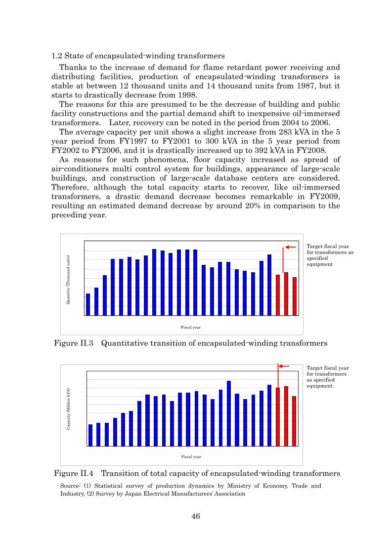
1.2 State of encapsulated-winding transformers Thanks to the increase of demand for flame retardant power receiving and
distributing facilities, production of encapsulated-winding transformers is stable at between 12 thousand units and 14 thousand units from 1987, but it starts to drastically decrease from 1998.
The reasons for this are presumed to be the decrease of building and public facility constructions and the partial demand shift to inexpensive oil-immersed transformers. Later, recovery can be noted in the period from 2004 to 2006.
The average capacity per unit shows a slight increase from 283 kVA in the 5 year period from FY1997 to FY2001 to 300 kVA in the 5 year period from FY2002 to FY2006, and it is drastically increased up to 392 kVA in FY2008.
As reasons for such phenomena, floor capacity increased as spread of air-conditioners multi control system for buildings, appearance of large-scale buildings, and construction of large-scale database centers are considered. Therefore, although the total capacity starts to recover, like oil-immersed transformers, a drastic demand decrease becomes remarkable in FY2009, resulting an estimated demand decrease by around 20% in comparison to the preceding year.
0
2
4
6
8
1 0
1 2
1 4
1 6
8 4 8 6 8 8 1 9 9 0 9 2 9 4 9 6 9 8 2 0 0 0 0 2 0 4 0 6 0 8
年 度
台数
(千台
)
Target fiscal year for transformers as specified equipment
Qua
ntity
(Tho
usan
d un
its)
Fiscal year
Figure II.3 Quantitative transition of encapsulated-winding transformers
0 .0
0 .5
1 .0
1 .5
2 .0
2 .5
3 .0
3 .5
4 .0
4 .5
8 4 8 6 8 8 1 9 9 0 9 2 9 4 9 6 9 8 2 0 0 0 0 2 0 4 0 6 0 8
年 度
容量
(百万kVA
)
Target fiscal year for transformers as specified equipment
Cap
acity
(Mill
ion
kVA)
Fiscal year
Figure II.4 Transition of total capacity of encapsulated-winding transformers Source: (1) Statistical survey of production dynamics by Ministry of Economy, Trade and Industry, (2) Survey by Japan Electrical Manufacturers’ Association
46
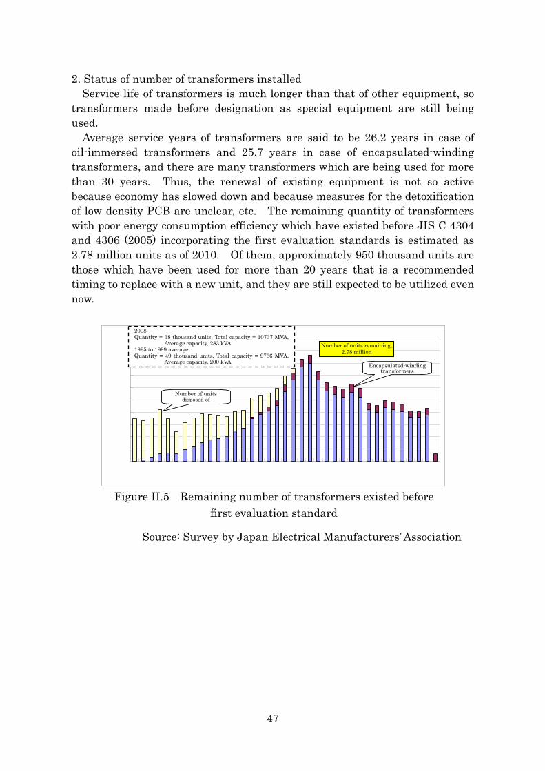
2. Status of number of transformers installed Service life of transformers is much longer than that of other equipment, so
transformers made before designation as special equipment are still being used.
Average service years of transformers are said to be 26.2 years in case of oil-immersed transformers and 25.7 years in case of encapsulated-winding transformers, and there are many transformers which are being used for more than 30 years. Thus, the renewal of existing equipment is not so active because economy has slowed down and because measures for the detoxification of low density PCB are unclear, etc. The remaining quantity of transformers with poor energy consumption efficiency which have existed before JIS C 4304 and 4306 (2005) incorporating the first evaluation standards is estimated as 2.78 million units as of 2010. Of them, approximately 950 thousand units are those which have been used for more than 20 years that is a recommended timing to replace with a new unit, and they are still expected to be utilized even now.
0
20
40
60
80
100
120
140
160
180
200
'70 '72 '74 '76 '78 '80 '82 '84 '86 '88 '90 '92 '94 '96 '98 '00 '02 '04 '06
2008 Quantity = 38 thousand units, Total capacity = 10737 MVA,
Average capacity, 283 kVA 1995 to 1999 average Quantity = 49 thousand units, Total capacity = 9766 MVA,
Average capacity, 200 kVA
残存台数278万台Number of units remaining,
2.78 million
モールド変圧器Encapsulated-winding transformers
廃却済み台数Number of units
disposed of
Figure II.5 Remaining number of transformers existed before
first evaluation standard
Source: Survey by Japan Electrical Manufacturers’ Association
47
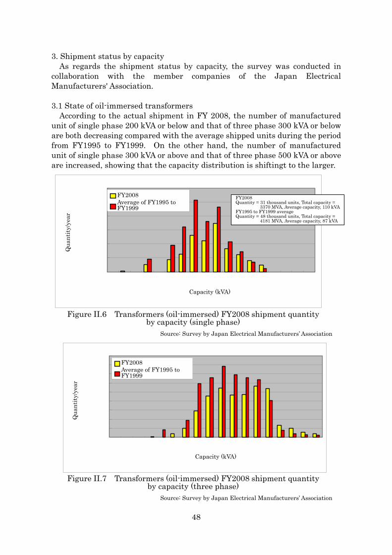
3. Shipment status by capacity As regards the shipment status by capacity, the survey was conducted in
collaboration with the member companies of the Japan Electrical Manufacturers' Association. 3.1 State of oil-immersed transformers According to the actual shipment in FY 2008, the number of manufactured unit of single phase 200 kVA or below and that of three phase 300 kVA or below are both decreasing compared with the average shipped units during the period from FY1995 to FY1999. On the other hand, the number of manufactured unit of single phase 300 kVA or above and that of three phase 500 kVA or above are increased, showing that the capacity distribution is shiftingt to the larger.
0
2 ,000
4 ,000
6 ,000
8 ,000
10 ,000
12 ,000
3 5
7.5 10
15
20
30
50
75
100
150
200
300
500
750
1000
1500
2000
容量(kVA)
台
数
/
年
2008年実績
1995~1999年平均
FY2008 Average of FY1995 to FY1999
FY2008
Qua
ntity
/yea
r
Quantity = 31 thousand units, Total capacity = 3370 MVA, Average capacity, 110 kVA
FY1995 to FY1999 average Quantity = 48 thousand units, Total capacity =
4181 MVA, Average capacity, 87 kVA
Capacity (kVA)
Figure II.6 Transformers (oil-immersed) FY2008 shipment quantity by capacity (single phase)
Source: Survey by Japan Electrical Manufacturers’ Association
0
1 ,000
2 ,000
3 ,000
4 ,000
5 ,000
6 ,000
7 ,000
8 ,000
9 ,000
3 5
7.5 10
15
20
30
50
75
100
150
200
300
500
750
1000
1500
2000
容量(kVA)
台
数
/
年
2008年実績
1995~1999年平均
Figure II.7 Transformers (oil-immersed) FY2008 shipment quantity
by capacity (three phase) Source: Survey by Japan Electrical Manufacturers’ Association
Qua
ntity
/yea
r
Capacity (kVA)
FY2008 Average of FY1995 to FY1999
48
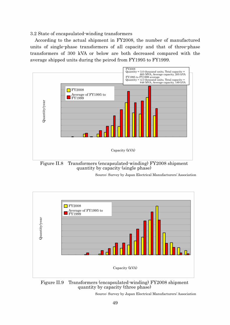
3.2 State of encapsulated-winding transformers According to the actual shipment in FY2008, the number of manufactured
units of single-phase transformers of all capacity and that of three-phase transformers of 300 kVA or below are both decreased compared with the average shipped units during the peirod from FY1995 to FY1999.
0
100200
300
400500
600
700800
900
3 5
7.5 10
15
20
30
50
75
100
150
200
300
500
750
1000
1500
2000
容量(kVA)
台
数
/
年
2008年実績
1995~1999年平均
0
200
400
600
800
1,000
1,200
1,400
1,600
1,800
3 5
7.5 10
15
20
30
50
75
100
150
200
300
500
750
1000
1500
2000
kVA)
2008年実績
1995~1999年平均
台
数
/
年
容量(
FY2008 Average of FY1995 toFY1999
Capacity (kVA)
Qua
ntity
/yea
r
FY2008 Average of FY1995 to FY1999
Capacity (kVA)
Qua
ntity
/yea
r
Source: Survey by Japan Electrical Manufacturers’ Association
Figure II.8 Transformers (encapsulated-winding) FY2008 shipment quantity by capacity (single phase)
FY2008Quantity = 3.0 thousand units, Total capacity =
605 MVA, Average capacity, 205 kVA FY1995 to FY1999 average Quantity = 4.5 thousand units, Total capacity =
846 MVA, Average capacity, 189 kVA
Figure II.9 Transformers (encapsulated-winding) FY2008 shipment quantity by capacity (three phase)
Source: Survey by Japan Electrical Manufacturers’ Association
49
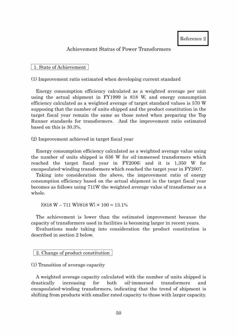
Reference 2
Achievement Status of Power Transformers 1. State of Achievement (1) Improvement ratio estimated when developing current standard
Energy consumption efficiency calculated as a weighted average per unit using the actual shipment in FY1999 is 818 W, and energy consumption efficiency calculated as a weighted average of target standard values is 570 W supposing that the number of units shipped and the product constitution in the target fiscal year remain the same as those noted when preparing the Top Runner standards for transformers. And the improvement ratio estimated based on this is 30.3%. (2) Improvement achieved in target fiscal year
Energy consumption efficiency calculated as a weighted average value using the number of units shipped is 636 W for oil-immersed transformers which reached the target fiscal year in FY2006; and it is 1,350 W for encapsulated-winding transformers which reached the target year in FY2007. Taking into consideration the above, the improvement ratio of energy consumption efficiency based on the actual shipment in the target fiscal year becomes as follows using 711W the weighted average value of transformer as a whole.
{(818 W − 711 W)/818 W} × 100 = 13.1%
The achievement is lower than the estimated improvement because the capacity of transformers used in facilities is becoming larger in recent years.
Evaluations made taking into consideration the product constitution is described in section 2 below. 2. Change of product constitution
(1) Transition of average capacity
A weighted average capacity calculated with the number of units shipped is drastically increasing for both oil-immersed transformers and encapsulated-winding transformers, indicating that the trend of shipment is shifting from products with smaller rated capacity to those with larger capacity.
50
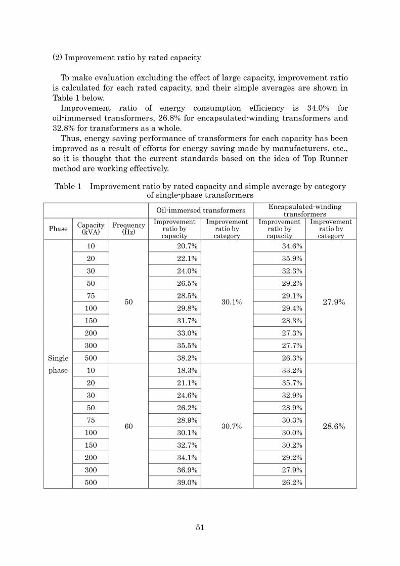
(2) Improvement ratio by rated capacity
To make evaluation excluding the effect of large capacity, improvement ratio is calculated for each rated capacity, and their simple averages are shown in Table 1 below.
Improvement ratio of energy consumption efficiency is 34.0% for oil-immersed transformers, 26.8% for encapsulated-winding transformers and 32.8% for transformers as a whole.
Thus, energy saving performance of transformers for each capacity has been improved as a result of efforts for energy saving made by manufacturers, etc., so it is thought that the current standards based on the idea of Top Runner method are working effectively. Table 1 Improvement ratio by rated capacity and simple average by category
of single-phase transformers Oil-immersed transformers Encapsulated-winding
transformers
Phase Capacity (kVA)
Frequency (Hz)
Improvement ratio by capacity
Improvement ratio by category
Improvement ratio by capacity
Improvement ratio by category
10 20.7% 34.6% 20 22.1% 35.9% 30 24.0% 32.3% 50 26.5% 29.2% 75 28.5% 29.1%
100 29.8% 29.4% 150 31.7% 28.3% 200 33.0% 27.3% 300 35.5% 27.7% 500
50
38.2%
30.1%
26.3%
27.9%
10 18.3% 33.2% 20 21.1% 35.7% 30 24.6% 32.9% 50 26.2% 28.9% 75 28.9% 30.3%
100 30.1% 30.0% 150 32.7% 30.2% 200 34.1% 29.2% 300 36.9% 27.9%
Single phase
500
60
39.0%
30.7%
26.2%
28.6%
51
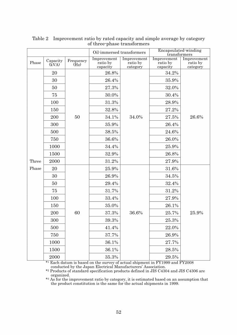
Table 2 Improvement ratio by rated capacity and simple average by category
of three-phase transformers Oil-immersed transformers Encapsulated-winding
transformers
Phase Capacity (kVA)
Frequency (Hz)
Improvement ratio by capacity
Improvement ratio by category
Improvement ratio by capacity
Improvement ratio by category
20 26.8% 34.2% 30 26.4% 35.9% 50 27.3% 32.0% 75 30.0% 30.4%
100 31.3% 28.9% 150 32.8% 27.2% 200 34.1% 27.5% 300 35.9% 26.4% 500 38.5% 24.6% 750 36.6% 26.0% 1000 34.4% 25.9% 1500 32.9% 26.8% 2000
50
31.2%
34.0%
27.9%
26.6%
20 25.9% 31.6% 30 26.9% 34.5% 50 29.4% 32.4% 75 31.7% 31.2%
100 33.4% 27.9% 150 35.0% 26.1% 200 37.3% 25.7% 300 39.3% 25.3% 500 41.4% 22.0% 750 37.7% 26.9% 1000 36.1% 27.7% 1500 36.1% 28.5%
Three Phase
2000
60
35.3%
36.6%
29.5%
25.9%
*1 Each datum is based on the survey of actual shipment in FY1999 and FY2008 conducted by the Japan Electrical Manufacturers’ Association.
*2 Products of standard specification products defined in JIS C4304 and JIS C4306 are organized.
*3 As for the improvement ratio by category, it is estimated based on an assumption that the product constitution is the same for the actual shipments in 1999.
52