Embed Size (px)
Citation preview

MOEJ
Final Report
Support for Low Carbon Promoting Projects through Intercity Cooperation
between Osaka and Ho Chi Minh (Promoting energy saving technologies)
February 2018
Oriental Consultants Co., Ltd.

2
Table of Contents
Chapter 1 Outline of the Survey ................................................................................................... 1 1.1 Background of the Survey ................................................................................................... 1 1.2 Purpose of the Survey .......................................................................................................... 1 1.3 Survey Implementation Structure ..................................................................................... 1
1.3.1 Outline of Implementation Structure ......................................................................... 1 1.3.2 Team OSAKA Network ................................................................................................ 2 1.3.3 Structure of HCMC....................................................................................................... 2
Chapter 2 Support for Ho Chi Minh City’s Implementation of Climate Change Action Plan . 4 2.1 Background .......................................................................................................................... 4 2.2 Current Status of the Climate Change Action Plan ......................................................... 4 2.3 Capacity Development Implementation ............................................................................ 4
Chapter 3 Implementation of the JCM Project Feasibility Study .............................................. 6 3.1 Overview ............................................................................................................................... 6 3.2 Technology to be Introduced ............................................................................................... 6
3.2.1 Heat Exchanger ............................................................................................................ 6 3.2.2 High-Efficiency Boiler .................................................................................................. 6
3.3 Energy Auditing ................................................................................................................... 6 3.4 Development of MRV Methodology for Green House Gas (GHG) Reduction and
Monitoring ............................................................................................................................ 9 3.4.1 Summary of the Methodology .................................................................................... 10 3.4.2 Eligibility Criteria ...................................................................................................... 11 3.4.3 Emission Reduction Calculation................................................................................ 11 3.4.3.1 Reference Emissions Calculation and Project Emissions Calculation ................ 11 3.4.3.2 Data and Parameters Fixed Ex-Ante ..................................................................... 12 3.4.4 Estimated Emission Reduction ................................................................................. 12
3.5 MRV System ....................................................................................................................... 13 3.6 Project Implementation Structure and Business Model ................................................. 15
3.6.1 Financial Analysis ...................................................................................................... 15 3.7 Administrative Procedures and Environmental Assessments ........................................... 19
3.8 Risks and Solutions ........................................................................................................... 19 Chapter 4 Energy Saving Action Plan ........................................................................................ 21
4.1 Background ........................................................................................................................ 21 4.2 Energy Saving Action Plan ............................................................................................... 21 4.3 Action Plan in Detail ......................................................................................................... 21
4.3.1 Background ................................................................................................................. 21 4.3.2 Introduction of JCM ................................................................................................... 21 4.3.2.1 Overview of JCM ..................................................................................................... 21 4.3.2.2 Introduction of JCM ................................................................................................ 22 4.3.3 Project Examples ........................................................................................................ 24 4.3.3.1 Waste Heat Recovery .............................................................................................. 24 4.3.3.2 Energy Efficient Boiler ............................................................................................ 27 4.3.3.3 Issues regarding JCM Project implementation ..................................................... 30 4.3.4 Future prospects ......................................................................................................... 30 4.3.4.1 Expansion of JCM Project ....................................................................................... 30 4.3.4.2 Trend of JCM ........................................................................................................... 30
Chapter 5 Promotion of Public-Private Partnerships (PPP) ..................................................... 30 Chapter 6 Workshops, Trainings and Meetings ........................................................................ 33
6.1 Overview ............................................................................................................................. 33 6.2 The 1st Field Survey .......................................................................................................... 33 6.3 The 1st City to City Collaboration Workshop Organized by MOE in Japan (July) ....... 33
6.3.1 Overview ...................................................................................................................... 33 6.3.2 Invited Guests ............................................................................................................. 34 6.3.3 Training Course in Japan .......................................................................................... 34

3
6.3.3.1 Visiting Osaka City hall .......................................................................................... 34 6.3.3.2 Visiting Heat Exchanger Factory ........................................................................... 34 6.3.3.3 Visiting Boiler Factory ............................................................................................ 34
6.4 The 2nd Field Survey ........................................................................................................ 35 6.4.1 Overview ...................................................................................................................... 35
6.6 Training in Japan organized by Osaka City (October) ................................................... 36 6.6.1 Overview ...................................................................................................................... 36 6.6.2 Invited Guests ............................................................................................................. 36 6.6.3 Training Course in Japan .......................................................................................... 37
6.7 The 3rd Field Survey ......................................................................................................... 37 6.7.1 Overview ...................................................................................................................... 37
6.8 The 2nd City to City Collaboration Workshop Organized by MoE in Japan ................ 38 6.8.1 Overview ...................................................................................................................... 38 6.8.2 Invited Guests ............................................................................................................. 38 6.8.3 Workshop in Japan ..................................................................................................... 38
Chapter 7 Future Tasks and Proposals ...................................................................................... 38

4
Figures
Figure 1: Survey Implementation Structure ....................................................................... 2 Figure 2: Example of Osaka City’s Energy Saving Projects ............................................... 5 Figure 3: GHG Inventory Development Process ................................................................. 5 Figure 4: Project Implementation Management through PDCA ....................................... 5 Figure 5: Spiral Heat Exchanger and Once-through Boiler ............................................... 6 Figure 6: Layout of Factory A ............................................................................................... 7 Figure 7: Layout of Factory B ............................................................................................... 8 Figure 8: Image before the Project ....................................................................................... 9 Figure 9: Project Image ......................................................................................................... 9 Figure 10: Monitoring Items and Points ............................................................................ 14 Figure 11: Monitoring Scheme and Process ...................................................................... 15 Figure 12: 1HK Type Heat Exchanger ............................................................................... 15 Figure 13: Project Implementation Structure ................................................................... 19 Figure 14: JCM Scheme ...................................................................................................... 22 Figure 15: Concept of Emission Reduction Calculation .................................................... 22 Figure 16: Overview of JCM Financing Flow .................................................................... 23 Figure 17: Example of International Consortium ............................................................. 23 Figure 18: Example of Schedule and Percentage of Subsidy............................................ 24 Figure 19: Reference Scenario (without project) ............................................................... 27 Figure 20: Project Scenario ................................................................................................. 27 Figure 21: Signing Ceremony for MOU ............................................................................. 31 Figure 22: Policy Dialogue .................................................................................................. 32 Figure 23: Kick-off Meeting ................................................................................................ 33 Figure 24: Factory of Kurose (Heat Exchanger) ................................................................ 34 Figure 25: Discussions at the Boiler Factory ..................................................................... 35 Figure 26: Workshop and Energy Auditing ....................................................................... 35 Figure 27: Discussions during the Training in Japan ...................................................... 37

5
Tables
Table 1: Roles of Participants ............................................................................................... 2 Table 2: Waste Heat Recovery Potentiality in 2 Factories ................................................. 8 Table 3: Energy Saving from Improvement of Boiler Operation ....................................... 9 Table 4: MRV methodology of JCM Project ......................................................................... 9 Table 5: Terms and Definitions .......................................................................................... 10 Table 6: Summary of the Methodology............................................................................... 10 Table 7: Eligibility Criteria ................................................................................................. 11 Table 8: Explanation and Parameter before Implementing ............................................. 12 Table 9: Data and Conditions for Calculating Emission Reductions ............................... 12 Table 10: Estimated Emission Reductions ........................................................................ 13 Table 11: Monitoring Parameters and Frequencies .......................................................... 13 Table 12: Heat Exchanger’s Specification and Number in the Factories ........................ 15 Table 13: Estimated Investment ........................................................................................ 15 Table 14: Result of Energy Saving in Factory A ............................................................... 16 Table 15: Cash Flow of the Project in Factory A ............................................................... 16 Table 16: Result of Energy Saving in Factory B (case 2) .................................................. 17 Table 17: Cash Flow of the Project in Factory B (case 2) ................................................. 17 Table 18: Result of Energy Saving in Factory B (case 3) .................................................. 17 Table 19: Cash Flow of the Project in Factory B (case 2 +case 3) .................................... 18 Table 20: Cash Flow of the Project in Factory A (with loan) ............................................ 18 Table 21: Cash Flow of the Project in Factory B (with loan for case 2) ........................... 18 Table 22: Cash Flow of the Project in Factory B (case 2 + 3) ........................................... 18 Table 23: Summary of Payback Period and IRRs ............................................................. 19 Table 24: Project Activities ................................................................................................. 33

6
Appendices
1. MRV 2. PDDs 2. Workshop Presentation Papers 3.

1
Chapter 1 Outline of the Survey 1.1 Background of the Survey
With a rapid economic growth rate, Vietnam shares the second highest growth rate of GHG emission among ASEAN member states (1995-2012). The World Bank (WB) Annual Report states that it has more than 3400 km of coastline, making Vietnam vulnerable to climate change. Various climate change mitigation measurements have been carried out so far, such as the introduction of an environmental protection tax, the Feed-in-Tariff (FIT) for wind power generation projects, and the application of Joint Crediting Mechanism (JCM). Moreover, according to the Intended Nationally Determined Contributions (INDC), Vietnam has pledged to reduce GHG emissions in 2030 by 8% compared to that of 2010. However, it is said that Vietnam can reduce GHG emissions by 25% in 2030 through effective management and attracting investments.
Ho Chi Minh City (HCMC) is the largest commercial city in Vietnam and has a population of 7 million. From the perspective of energy consumption, HCMC accounts for 20% of total electric power consumption and 25% ~ 30% of total fuel consumption in Vietnam. Population growth increased the demand for electricity and caused the price of power to increase dramatically. HCMC has implemented various policies related to energy saving and renewable energy and called for financial and technical support from donor countries including Japan.
Osaka city, one of the biggest cities in Japan, has gained a lot of experience with the mitigation of climate change through implementing mitigation measures such as promoting renewable energies and energy savings that contributed to achieving the GHG emission reduction goal of Japan.
Since they became business partner cities in 1997, HCMC and Osaka City have been collaborating in the fields of the promotion of green ports and harbors and the improvement of water supply and sewage systems.
In 2013, HCMC and Osaka City signed a Memorandum of Understanding (MoU) for developing a low-carbon city. Based on this plan, Osaka City has supported low carbon development technologies in Ho Chi Minh by using the JCM scheme which was agreed upon by the Vietnamese Government and the Japanese Government. Furthermore, during the policy dialogue with Ho Chi Minh City Climate Change Bureau in December 2016, it was agreed that it needs to specify project actions and an implementation plan to realize the plan effectively. And Osaka city agreed to share knowledge and know-how on promoting energy efficiency improvement projects in factories.
Under these circumstances, capacity building workshops were implemented in Ho Chi Minh to increase organizational and operational capacity of Ho Chi Minh stakeholders regarding climate change mitigation actions. Focusing on the textile industry, which is one of the pillar industries in Ho Chi Minh, efforts were made to introduce energy efficiency promoting technologies such as waste heat recovery systems and high efficiency boilers through the JCM scheme.
1.2 Purpose of the Survey Through the tasks listed below, the survey supported HCMC by developing potential JCM
projects to contribute to the realization of a low-carbon city. 1. Support to develop climate change action plans2. Develop potential JCM projects promoting energy saving at factories.
1.3 Survey Implementation Structure 1.3.1 Outline of Implementation Structure
Oriental Consultants Co., Ltd. (OC) is the main implementer of the survey. Through cooperation with Osaka City and HCMC Department of Natural Resources and Environment (DONRE), OC conducted this survey.
Private companies that belong to Team OSAKA network helped organize workshops in Japan and conduct energy auditing in factories. The implementation structure of this survey is shown in Figure 1 and the roles of participants are shown in Table 1.

2
Figure 1: Survey Implementation Structure
Table 1: Roles of Participants Roles Co-implementers Tasks
Main implementer Oriental Consultants Co., Ltd.
Coordination of between Japan and HCMC side; business model and MRV development. Development of the final report of the survey.
Capacity development support
Osaka City Implementation and support of capacity development
Energy auditing Japan Textile Consultants Center (JTCC)
Implementation of energy auditing
Boiler provider Nippon Thermoener Co., Ltd
Provide technology and advice regarding boiler
Heat exchanger provider
Kurose Chemical Equipment Co., Ltd.
Provide technology and advices regarding spiral heat exchanger
Support on JCM implementation
Yuko Keiso Co., Ltd. Provide advices regarding JCM project implementation
Financial adviser Resona Bank, Limited
Provide advices regarding financial aspects to implement JCM projects
1.3.2 Team OSAKA Network The Team OSAKA Network is a platform in which business operators with environmental
technologies in Osaka and other prefectures in the Kansai region, in cooperation with Osaka City Government, the Osaka Prefectural Government, the Global Environment Centre Foundation (GEC), and universities, create and build low carbon projects in order to develop low carbon societies in Asian cities. This network helps business operators to expand their business overseas, consequently revitalizing economies in Osaka and the Kansai region and helping to strengthen Japan’s important role in the international environmental arena. In this project, the email magazine of the network updated by Osaka City was circulated between participants to share information about JCM and other climate change mitigation technologies.
1.3.3 Structure of HCMC HCMC Climate Change Steering Committee is responsible for promoting low-carbon
development in HCMC. The members of the committee are the entire departments of HCMC.

3
An advisory group and the Climate Change Bureau are functioning under the committee as sub-organizations. The Climate Change Bureau is set up within the Department of Natural Resources and Environment (DONRE). In this project, the project team worked with HCMC Climate Change Bureau to conduct the survey.

4
Chapter 2 Support for Ho Chi Minh City’s Implementation of Climate Change Action Plan 2.1 Background
Under the memorandum of understanding (MOU) signed in 2013 between HCMC and Osaka, Osaka city supported HCMC to complete its Climate Change Action Plan (CCAP). Through feasibility studies on JCM projects under city-to-city collaboration supported by the Ministry of the Environment, Japan (MOE), Osaka city continuously supported HCMC. According to an interview survey conducted in 2015, the CCAP was not broken down to the project level and there is lack of capacity and know-how on how to manage the progress of implementing projects of the plan. In response to that, in 2016, the two cities signed “the MoU on the collaboration for developing low carbon city in HCMC”. The main content of the MOU is given as below. Support on the capacity development projects for implementation of HCMC CCAP
(2016-2020) Share information and know-how on GHG emission inventory development and
monitoring Create projects for developing HCMC into a low-carbon city Awareness-raising in regard to global warming
2.2 Current Status of the Climate Change Action Plan The city is promoting 3 types of projects based on the CCAP.
1. Research and studies about CO2 emission (Not funded by HCMC)
2. Projects funded by HCMC (Most are small projects with budget less than 10 Million JPY)
3. Projects implemented by private companies (This kind of projects are planned to be implemented through cooperation with donors and private companies.)
Regarding the first two types, DONRE prepares a plan for each year and submits it to the committee for approval. For the third type, project lists need to be prepared by coordinating and working with other related bureaus.
The projects that need to be implemented in the future are as follows. 1. Green buildings 2. Traffic congestion mitigation 3. Saigon River tourism development 4. Subway projects supported by Japan
2.3 Capacity Development Implementation The following are the issues in HCMC regarding the implementation of CCAP.
1. Visualization of low carbon development projects 2. Know-how on the calculation of GHG emissions 3. Appropriate management of progress of CCAP
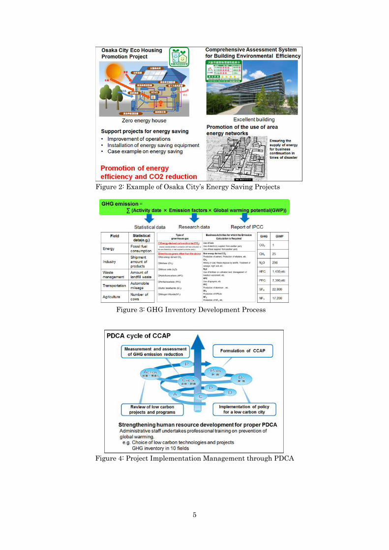
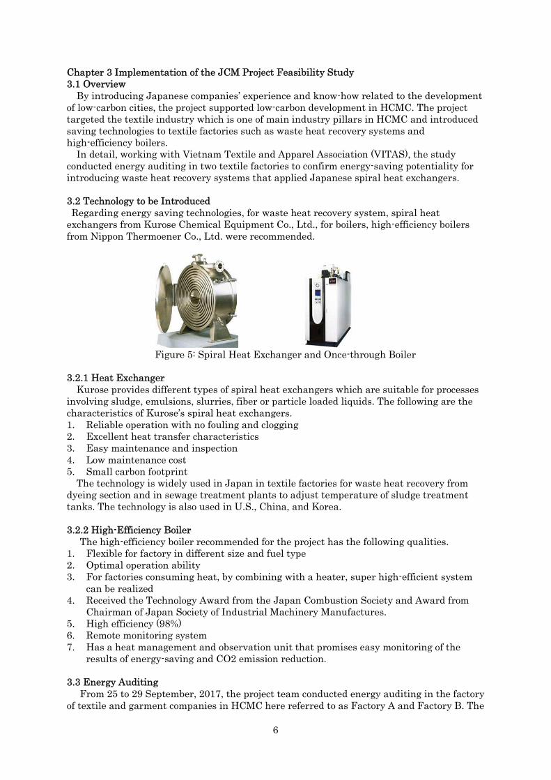
In response to the issues, in addition to an energy saving action plan in industry sector, Osaka city introduced its plan and practices such as the climate change mitigation action plan, energy saving promotion projects, and methods of energy saving evaluation through workshops and training courses.
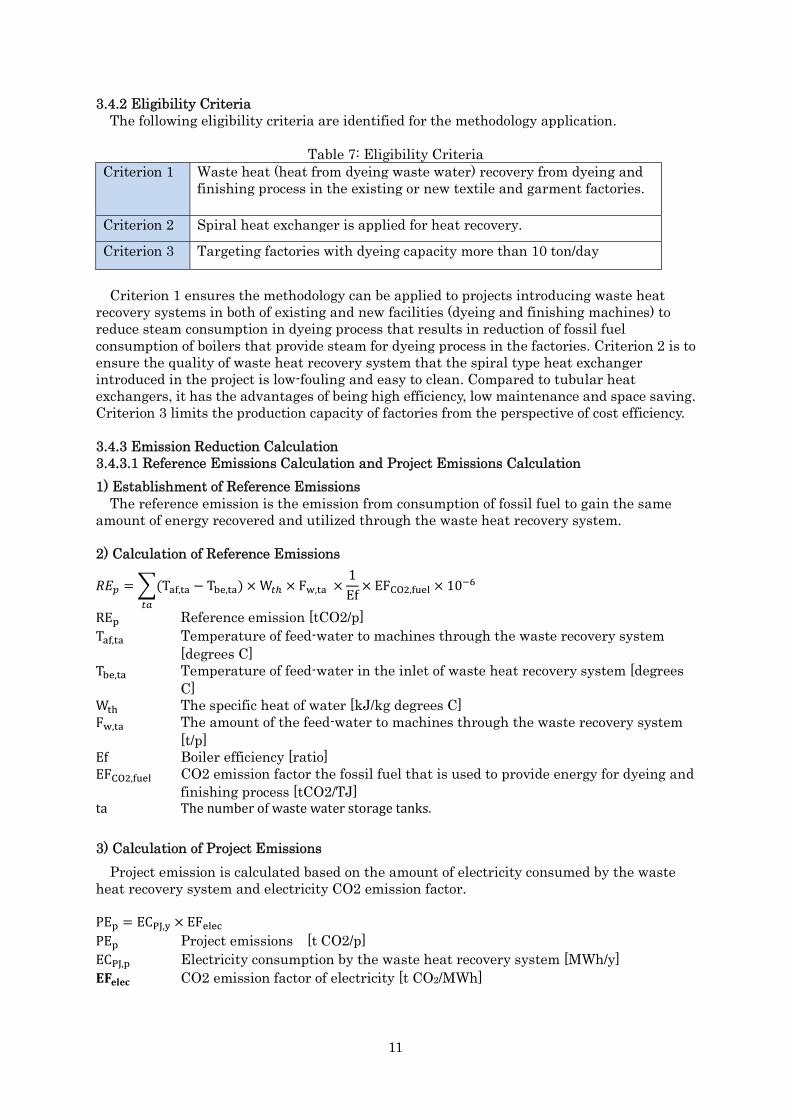
Moreover, Osaka’s practice on the development of GHG inventory and the management of project implementation through PDCA cycle were also shared.
5
Figure 2: Example of Osaka City’s Energy Saving Projects
Figure 3: GHG Inventory Development Process
Figure 4: Project Implementation Management through PDCA
6
Chapter 3 Implementation of the JCM Project Feasibility Study 3.1 Overview
By introducing Japanese companies’ experience and know-how related to the development of low-carbon cities, the project supported low-carbon development in HCMC. The project targeted the textile industry which is one of main industry pillars in HCMC and introduced saving technologies to textile factories such as waste heat recovery systems and high-efficiency boilers.
In detail, working with Vietnam Textile and Apparel Association (VITAS), the study conducted energy auditing in two textile factories to confirm energy-saving potentiality for introducing waste heat recovery systems that applied Japanese spiral heat exchangers.
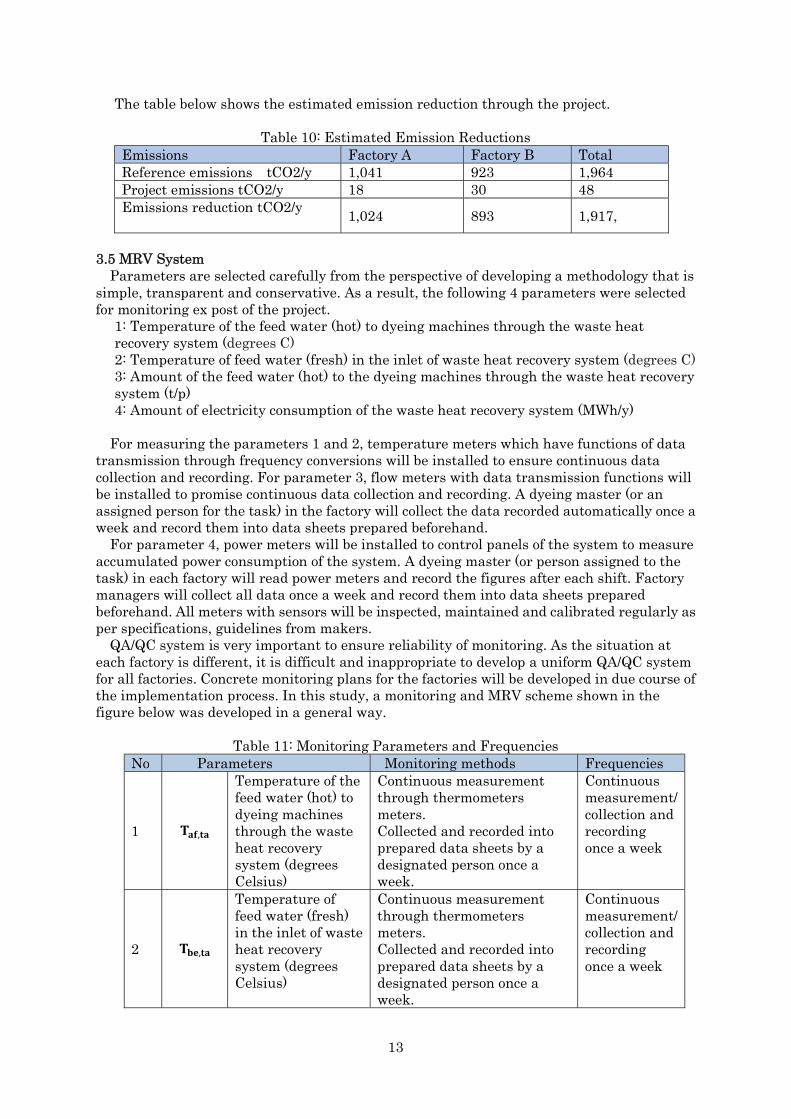
3.2 Technology to be Introduced Regarding energy saving technologies, for waste heat recovery system, spiral heat
exchangers from Kurose Chemical Equipment Co., Ltd., for boilers, high-efficiency boilers from Nippon Thermoener Co., Ltd. were recommended.
Figure 5: Spiral Heat Exchanger and Once-through Boiler
3.2.1 Heat Exchanger Kurose provides different types of spiral heat exchangers which are suitable for processes
involving sludge, emulsions, slurries, fiber or particle loaded liquids. The following are the characteristics of Kurose’s spiral heat exchangers. 1. Reliable operation with no fouling and clogging 2. Excellent heat transfer characteristics 3. Easy maintenance and inspection 4. Low maintenance cost 5. Small carbon footprint
The technology is widely used in Japan in textile factories for waste heat recovery from dyeing section and in sewage treatment plants to adjust temperature of sludge treatment tanks. The technology is also used in U.S., China, and Korea.
3.2.2 High-Efficiency Boiler The high-efficiency boiler recommended for the project has the following qualities.
1. Flexible for factory in different size and fuel type 2. Optimal operation ability 3. For factories consuming heat, by combining with a heater, super high-efficient system
can be realized 4. Received the Technology Award from the Japan Combustion Society and Award from
Chairman of Japan Society of Industrial Machinery Manufactures. 5. High efficiency (98%) 6. Remote monitoring system 7. Has a heat management and observation unit that promises easy monitoring of the
results of energy-saving and CO2 emission reduction.
3.3 Energy Auditing From 25 to 29 September, 2017, the project team conducted energy auditing in the factory
of textile and garment companies in HCMC here referred to as Factory A and Factory B. The

7
main purpose of the auditing was to confirm the potentiality of waste water heat recovery and energy saving by observing the status and working condition of boilers dyeing machines, and measuring the temperature and volume of waste water.
The waste heat which was recovered from project implementation can be used for preheating feed water to dyeing machines or boilers. As the temperature of feed water is adjusted in dyeing machines by steam provided by boilers, using the waste heat recovered to heat up the feed water helps to reduce steam consumption, which reduces the fuel consumption of boilers.
Factory A Factory A is a company specialized in manufacturing and trading all types of cotton fabrics
(especially denim and khaki), as well as garment production. Major materials used in the factory are polyester blend fabric and 100% cotton. The
factory runs 24-hours/day from Monday to Saturday in 3 shifts and off on Sunday only. Yearly working days are 300 days. The layout of the factory is as follows.
Figure 6: Layout of Factory A
It was observed that there is a possibility of waste heat recovery from dyeing, scouring or bleaching processes in the factory. For example, the data measured at the drainage outlet of dyeing machines is almost around 75 degree C.
There are 2 boilers used in the factory (15 ton and 10 ton) using coal as a fuel. The daily coal consumption of the boilers is around 25~30 ton and daily steam consumption is around 144 ton. As the boilers used now are quite new with 69.5% efficiency, the study concluded that at the moment, it is not necessary to replace of any of boiler in the factory. However, some actions were proposed to improve the performance of boilers such as introducing a management system which automatically controls the draft fan/induced draft fan/feed pump based on the demand for water flow, steam flow, furnace pressure and air ratio.
Factory B The factory belongs to military mainly produces uniform for governments officers, police
and military. The factory owns two coal steam boilers (15 ton and 10 ton) for steam production and one
heating boiler with 45,000,000Kcal capacity is used for drying. The factory runs 24 hours a day in 3 shifts. Total working days in a year are 300 days. The
following is the layout of factory.
Targeted facilities
Boiler room
Boiler
Scouring/Bleaching
Washing machine

8
Figure 7: Layout of Factory B
Technology for recovering and applying waste heat in this project is the heat exchanger of Kurose Co., Ltd, which can be designed based on actual conditions of the factories. In order to design the suitable systems, the energy auditing collected basic information on the temperature and volume of waste water from the factories.
However, regarding the high effective boiler, most factories in HCMC including textile factories are using coal boilers and it was determined that demand for Japanese high efficiency gas and oil boilers is very low and they are not economically viable.
The summary of energy auditing results in factories is as follows
Table 2: Waste Heat Recovery Potentiality in 2 Factories
Factory Methods Target facilities Recovery rate Unit
Energy saving G cal/year
Factory A
Waste heat recovery ①High recovery case 59.5 3,132
②Low recovery case 50.0 2,632
Heat insulation ③ Cylinder dryer only 78 pcs 141
④+washer 498
①+④ 3,630
②+③ 2,773
Factory B
Waste heat recovery
①High recovery case 61.0 2,500
②Low recovery case 52.0 2,100
⑤Boiler scrubber 50.0 437
Heat insulation ③Cylinder dryer only 25 pcs 183
④+washer 554
①+④+⑤ 3,492
②+③ 2,283
Wastewater treatment facility
Boiler room
Scouring, mercerizer Pad Steamer
Stenters

9
Table 3: Energy Saving from Improvement of Boiler Operation
Section Methods Before After (max) After (min)
Coal ton/year
G cal /year
Coal ton/year
G cal /year
Coal ton/year
G cal /year
Factory A Boiler
1) Operation 2)Management 3) Drain
4,125 20,625 3,630 18,150 3,855 19,275
4) Heat retention 4.4 21.8 0.9 4.4 - -
Factory B Boiler
1) Operation 2) Management 3) Drain
3,000 15,000 2,625 13,125 2,800 14,000
4) Heat retention 50.3 251.4 10.1 50.4 - -
Figure 8: Image before the Project
Figure 9: Project Image
Based on the energy auditing results, the study developed potential JCM projects by introducing heat exchangers (spiral type) to recover waste heat from the factories.
3.4 Development of MRV Methodology for Green House Gas (GHG) Reduction and Monitoring
In order to develop MRV methodologies for the waste heat recovery and high efficiency boiler introduction projects, the following existing methodologies are observed as references.
Table 4: MRV methodology of JCM Project Methodologies Explanations≪CDM Methodologies≫AMS-II.I.: Efficient utilization of waste energy in industrial facilities (Version 1.0) AM0044: Energy efficiency improvement projects - boiler rehabilitation or replacement in industrial and district heating sectors (Version 02.0)
Since there has not been anapproved JCM methodology related to waste heat recovery from the dyeing process in textile industry, the CDM and JCM feasibility

10
≪JCM Methodologies≫MN_AM002 “Replacement and Installation of High Efficiency Heat Only Boiler (HEB) for Hot Water Supply Systems” ID_AM001 “Power Generation by Waste Heat Recovery in Cement Industry”
study regarding waste heat recovery from industrial process were referenced to develop the methodology.
3.4.1 Summary of the Methodology The methodology is applied for recovering waste heat from dyeing and finishing processes
in textile and garment factories. Figures in the previous section show the GHG emission conditions before and after the
project.
Table 5: Terms and Definitions Terms DefinitionsTextile dyeing and finishing The procedures from fabric pre-treatment to finishing
in textile and garment dyeing houses. Including main procedures of fabric pre-treatment, dyeing and finishing (washing, drying) that is the chemical and physical treatments of consuming heat and steam.
Waste heat Heat energy of boiler exhaust and/or waste water from dyeing machines
Table 6: Summary of the Methodology Items Summary GHG emission reduction measures
Recovered waste heat is used for preheating feed-water to boilers and dyeing machines so that reduce fuel consumption of boilers that provide steam for dyeing and finishing process.
Calculation of reference emissions
Reference emission is calculated based on the amount of wasteenergy/heat utilized, boiler efficiency and CO2 emission factor of the fossil fuel that is used for providing energy to the dyeing process. Conservative values of the parameters are used to ensure the reference emission is lower than BaU emission. For example, 100% is used for the efficiency of boiler in the reference scenario.
[(Temperature of feed water in the inlet of the waste heat recovery system) - (Temperature of feed water in the outlet of the waste heat recovery system)] *(The amount of the feed water providing to dyeing machines in the project)*(the specific heat of water)/ (boiler efficiency)* (CO2 emission factor the fossil fuel that is used to provide energy for dyeing and finishing process).
Calculation of project emissions
The project emission is calculated based on the electricity consumption of waste heat recovery system and CO2 emission factor of electricity
Monitoring parameters
The following parameters need to be monitored. 1. The temperature of the feed-water to the heat exchange system in the project (degree C) 2. The amount and temperature of the feed-water to the dyeing
machines through the heat exchange system in the project (degree C) and (t/p)
3. The amount of electricity consumed by the waste heat recovery system (Mwh/p)
11
3.4.2 Eligibility Criteria The following eligibility criteria are identified for the methodology application.
Table 7: Eligibility Criteria Criterion 1 Waste heat (heat from dyeing waste water) recovery from dyeing and
finishing process in the existing or new textile and garment factories.
Criterion 2 Spiral heat exchanger is applied for heat recovery.
Criterion 3 Targeting factories with dyeing capacity more than 10 ton/day
Criterion 1 ensures the methodology can be applied to projects introducing waste heat recovery systems in both of existing and new facilities (dyeing and finishing machines) to reduce steam consumption in dyeing process that results in reduction of fossil fuel consumption of boilers that provide steam for dyeing process in the factories. Criterion 2 is to ensure the quality of waste heat recovery system that the spiral type heat exchanger introduced in the project is low-fouling and easy to clean. Compared to tubular heat exchangers, it has the advantages of being high efficiency, low maintenance and space saving. Criterion 3 limits the production capacity of factories from the perspective of cost efficiency.
3.4.3 Emission Reduction Calculation 3.4.3.1 Reference Emissions Calculation and Project Emissions Calculation 1) Establishment of Reference Emissions
The reference emission is the emission from consumption of fossil fuel to gain the same amount of energy recovered and utilized through the waste heat recovery system.
2) Calculation of Reference Emissions
��� ���T��,� T��,� � W�� � F�,� �1Ef � EF���,������
� 10��
RE� Reference emission [tCO2/p] T��,� Temperature of feed-water to machines through the waste recovery system
[degrees C] T��,� Temperature of feed-water in the inlet of waste heat recovery system [degrees
C] W� The specific heat of water [kJ/kg degrees C] F�,� The amount of the feed-water to machines through the waste recovery system
[t/p] Ef Boiler efficiency [ratio] EF���,���� CO2 emission factor the fossil fuel that is used to provide energy for dyeing and
finishing process [tCO2/TJ] ta Thenumberofwastewaterstoragetanks.
3) Calculation of Project Emissions Project emission is calculated based on the amount of electricity consumed by the waste
heat recovery system and electricity CO2 emission factor.
PE� � EC��,� � EF����PE� Project emissions [t CO2/p] EC��,� Electricity consumption by the waste heat recovery system [MWh/y] ������ CO2 emission factor of electricity [t CO2/MWh]

12
4) Calculation of Emission Reduction ER� � RE� PE�RE� Reference emissions [t CO2/p] ��� Project emissions [t CO2/p]
3.4.3.2 Data and Parameters Fixed Ex-Ante The source of each data and parameter fixed ex-ante is listed as below.
Table 8: Explanation and Parameter before Implementing Parameter Data explanation SourceEf Boiler efficiency
Factory A: 69.5% Factory B: 70% 100% is used for conservativeness. However, for energy saving to financial analysis actual boiler efficiency is applied.
Textile factories
EF���,���� CO2 emission factor of the fuel used for steam generation Coal: 87.3 tCO2/TJ (lower case of default value)
2006 IPCC Guidelines for National Greenhouse Gas Inventories. Table 1.4, Chapter 1, Volume 2. (Table 1.4)
EF���� CO2 emission factor of electricity In the case of grid: 0.8154 tCO2/MWh
In case of private power generation (diesel): 0.8 t CO2/MWh
Grid emission factor published by the host country (If there is no any requirement from Joint Committee) (IGES's List of Grid Emission Factors updated in August 2017).
(Table I.F.1, Small Scale CDM Methodology: AMS I.F. ver.2)
3.4.4 Estimated Emission Reduction The estimated emission reduction from the factories by introducing a spiral heat exchanger
waste heat recovery system is given as follows.
Table 9: Data and Conditions for Calculating Emission Reductions Items Factory A Factory B Operation days d/y 300 300 Feed water temperature to the waste heat recovery system
30
Feed water temperature to dyeing machines through the system
63 65
Specific heat capacity of water kJ/kg degrees C
4.184
Amount of feed water to dyeing machines through the waste heat recovery system t/h
24t/h 24t/h
Heat efficiency of boilers % 69.5 70 Emission factor of boiler fuel tCO2/TJ 87.3 Capacity of waste heat exchange system (pumps) kW 6 6
13
The table below shows the estimated emission reduction through the project.
Table 10: Estimated Emission Reductions Emissions Factory A Factory B TotalReference emissions tCO2/y 1,041 923 1,964Project emissions tCO2/y 18 30 48Emissions reduction tCO2/y 1,024 893 1,917,
3.5 MRV System Parameters are selected carefully from the perspective of developing a methodology that is
simple, transparent and conservative. As a result, the following 4 parameters were selected for monitoring ex post of the project.
1: Temperature of the feed water (hot) to dyeing machines through the waste heat recovery system (degrees C)2: Temperature of feed water (fresh) in the inlet of waste heat recovery system (degrees C)3: Amount of the feed water (hot) to the dyeing machines through the waste heat recovery system (t/p) 4: Amount of electricity consumption of the waste heat recovery system (MWh/y)
For measuring the parameters 1 and 2, temperature meters which have functions of data transmission through frequency conversions will be installed to ensure continuous data collection and recording. For parameter 3, flow meters with data transmission functions will be installed to promise continuous data collection and recording. A dyeing master (or an assigned person for the task) in the factory will collect the data recorded automatically once a week and record them into data sheets prepared beforehand.
For parameter 4, power meters will be installed to control panels of the system to measure accumulated power consumption of the system. A dyeing master (or person assigned to the task) in each factory will read power meters and record the figures after each shift. Factory managers will collect all data once a week and record them into data sheets prepared beforehand. All meters with sensors will be inspected, maintained and calibrated regularly as per specifications, guidelines from makers.
QA/QC system is very important to ensure reliability of monitoring. As the situation at each factory is different, it is difficult and inappropriate to develop a uniform QA/QC system for all factories. Concrete monitoring plans for the factories will be developed in due course of the implementation process. In this study, a monitoring and MRV scheme shown in the figure below was developed in a general way.
Table 11: Monitoring Parameters and Frequencies No Parameters Monitoring methods Frequencies
1 ���,��
Temperature of the feed water (hot) to dyeing machines through the waste heat recovery system (degrees Celsius)
Continuous measurement through thermometers meters. Collected and recorded into prepared data sheets by a designated person once a week.
Continuous measurement/collection and recording once a week
2 ���,��
Temperature of feed water (fresh) in the inlet of waste heat recovery system (degrees Celsius)
Continuous measurement through thermometers meters. Collected and recorded into prepared data sheets by a designated person once a week.
Continuous measurement/ collection and recording once a week

14
3 ��,��
Amount of the feed water (hot) to the dyeing machines through the waste heat recovery system (t/p)
Continuous measurement through flow meters. Collected and recorded into prepared data sheets by a designated person once a week.
Continuous measurement/collection and recording once a week
4 ����,�
Amount of the electricity consumption of the waste heat recovery system (MWh/p)
Continuous measurement through power meters. Collected and recorded into prepared data sheets by a designated person once a week.
Continuous measurement/collection and recording once a week
Figure 10: Monitoring Items and Points
MRV methodology in detail will be developed by OC consulting and together with JCM representative participant and project owners. Monitoring is implemented by the project owner based on the MRV methodology. Parameters will be measured consistently and automatically by power and flow meters. However, it is necessary for a designated person from the factory to collect the data periodically and record it onto a prepared data sheet. The recorded data should be reported to the section which is responsible for the JCM project. The section should check the data and prepare a data sheet which calculates emission reduction on a monthly basis. The monthly prepared data should be checked and compiled by a person who is responsible for the JCM project and reported to the representative participant to submit to the Joint Committee.
The representative participant is responsible for training the staff of the factory (project owner) on the implementation of monitoring and OC will support the representative participant if necessary.

15
Figure 11: Monitoring Scheme and Process
3.6 Project Implementation Structure and Business Model 3.6.1 Financial Analysis
The waste heat recovery system of the study consists of heat exchangers and their surrounding equipment ones such as pumps, flowmeters and a control panel. Spiral heat exchanger type KSH-1HK with different sizes like 56m2, 37m2 and 18m2 are applied for the project.
For Factory A, the project recommended to install a waste heat recovery system with the capacity of 56 m2. For Factory B, a system with the capacity of 37 m2 for recovering waste heat from dyeing process and a system with capacity of 18 m2 for recovering waste heat from the scrubber of boiler were recommended.
Table 12: Heat Exchanger’s Specification and Number in the Factories
Case Factories Model Size of heat exchangers Material Regulations Set
1 Factory A KSH-1HK 56 m2 SUS316 None 1 2 Factory B KSH-1HK 37 m2 SUS316 None 1 3 Factory B KSH-1HK 18 m2 SUS316 None 1
Figure 12: 1HK Type Heat Exchanger
Table 13: Estimated Investment KSH-1HK Initial cost Heating surface area
Switchboard
Pump・flowmeter ・control panel and relating work
Delivery ・Packing Tax Total
Representative participant (Supported by OC if necessary)

16
56 m2 910 1,485 50 193 2,588 37 m2 710 1,485 50 163 2,368 18 m2 380 1,300 50 130 1,820
As per the Vietnam Economic Partnership Agreement (JVEPA), the tax rate for heat exchangers and pumps is assumed to be zero, for flowmeters, it seems to be 2%. The current rate of value added tax in Vietnam is 10%.
The initial costs for equipment and installation of waste heat recovery systems are estimated based on the information from the technology providers (heat exchanger, pumps and meters) and investigating related sources. The amounts of waste heat that can be recovered by the systems are estimated as per data and information collected from the factories and specification of the heat exchangers. The amount of cost of coal reduced by applying waster heat recovered by the project is counted as the benefit of each factory. The cash flow of the factories for the project is given in the tables below.
Table 14: Result of Energy Saving in Factory A Waste water Feed water Flow rate(ton/h)
Inlet temp (degrees C)
Outlet temp(degrees C)
Flow rate(ton/h)
Inlet temp(degrees C)
Outlet temp(degrees C)
32 75 48.2 26 30 63.5
Working hours (h/day)
Operating days (day/year)
Operation rate (%)
Recovered heat energy(G cal/year)
Caloric value of coal (K cal/kg)
Coal equivalent (ton/year)
24 300 50 3,135 5,900 759
Boiler efficiency (%)
Coal price (JPY/ton)
Energy saved (10000 JPY/year)
70 10,000 759
For the calorific value of coal, the value of Indonesian coal used for calculation is higher than the actual value of coals used in the factories. The table below shows the cash flow for the case in which 50% of the initial cost would be subsidized by MOE under the JCM scheme and the remaining 50% would be prepared by factory side.
Table 15: Cash Flow of the Project in Factory A
The result of waste heat recovery from the dyeing section in Factory B is summarized as
No Items Total ConstructionPeriod
0 1 2 3 4 5 6 7 8 9 101 Cash inflow 7,590 0 759 759 759 759 759 759 759 759 759 759
1.1 Saved coal cost 7,590 0 759 759 759 759 759 759 759 759 759 7592 Cash outflow 1,814 1,314 50 50 50 50 50 50 50 50 50 50
2.1 Initial cost 1,314 1,314 0 0 0 0 0 0 0 0 0 02.2 Maintenance 500 0 50 50 50 50 50 50 50 50 50 50
3 Net cash flow 5,776 -1,314 709 709 709 709 709 709 709 709 709 709
Payback period (year) 1.9
Net benefit 5,776IRR 53%

17
follows.
Table 16: Result of Energy Saving in Factory B (case 2) Waste water Feed water Flow rate(ton/h)
Inlet temp (degrees C)
Outlet temp(degrees C)
Flow rate(ton/h)
Inlet temp(degrees C)
Outlet temp(degrees C)
32 83.8 51 24 30 71
Working hours (h/day)
Operating days (day/year)
Operation rate (%)
Recovered heat energy(G cal/year)
Caloric value of coal (K cal/kg)
Coal equivalent (ton/year)
24 300 50 2,409 5,900 583
Boiler efficiency (%)
Coal price (JPY/ton)
Energy saved (10000 JPY/year)
70 10,000 583
The cash flow for the case of in case of 50% subsidy through JCM is given below.
Table 17: Cash Flow of the Project in Factory B (case 2)
The following is the result of energy saving in Factory B by recovering waste heat from the water of boiler scrubber.
Table 18: Result of Energy Saving in Factory B (case 3) Waste water Feed water Flow(ton/h)
Inlet temp (degrees C)
Outlet temp(degrees C)
Inlet temp(degrees C)
Flow(ton/h)
Outlet temp(degrees C)
10 52.3 40.15 6.24 28 47.47
Working hours (h/day)
Operating days (day/year)
Operation rate (%)
Recovered heat energy (G cal/year)
Caloric value of coal (K cal/kg)
Coal equivalent (ton/year)
24 300 50 437 5,900 105
Boiler efficiency (%)
Coal price (JPY/ton)
Energy saved(10000 JPY/year)
70 10,000 105
The following table shows the cash flow for the case that combines the previous two cases.
No Items Total ConstructionPeriod
0 1 2 3 4 5 6 7 8 9 101 Cash inflow 5,830 0 583 583 583 583 583 583 583 583 583 583
1.1 Saved coal cost 5,830 0 583 583 583 583 583 583 583 583 583 5832 Cash outflow 1,704 1,204 50 50 50 50 50 50 50 50 50 50
2.1 Initial cost 1,204 1,204 0 0 0 0 0 0 0 0 0 02.2 Maintenance 500 0 50 50 50 50 50 50 50 50 50 50
3 Net cash flow 4,126 -1,204 533 533 533 533 533 533 533 533 533 533
Payback period (year) 2.3
Net benefit 4,126IRR 43%
18
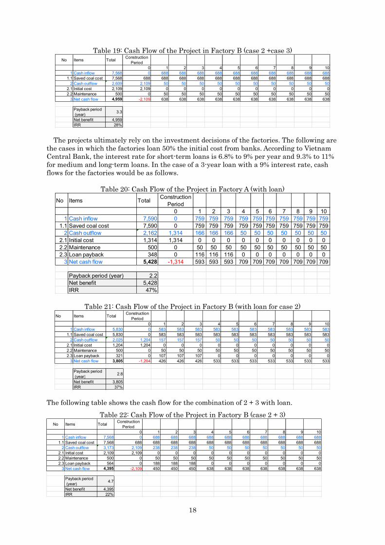
Table 19: Cash Flow of the Project in Factory B (case 2 +case 3)
The projects ultimately rely on the investment decisions of the factories. The following are the cases in which the factories loan 50% the initial cost from banks. According to Vietnam Central Bank, the interest rate for short-term loans is 6.8% to 9% per year and 9.3% to 11% for medium and long-term loans. In the case of a 3-year loan with a 9% interest rate, cash flows for the factories would be as follows.
Table 20: Cash Flow of the Project in Factory A (with loan)
Table 21: Cash Flow of the Project in Factory B (with loan for case 2)
The following table shows the cash flow for the combination of 2 + 3 with loan. Table 22: Cash Flow of the Project in Factory B (case 2 + 3)
No Items Total ConstructionPeriod
0 1 2 3 4 5 6 7 8 9 101 Cash inflow 7,568 0 688 688 688 688 688 688 688 688 688 688
1.1 Saved coal cost 7,568 688 688 688 688 688 688 688 688 688 688 6882 Cash outflow 2,609 2,109 50 50 50 50 50 50 50 50 50 50
2.1 Initial cost 2,109 2,109 0 0 0 0 0 0 0 0 0 02.2 Maintenance 500 0 50 50 50 50 50 50 50 50 50 50
3 Net cash flow 4,959 -2,109 638 638 638 638 638 638 638 638 638 638
Payback period (year) 3.3
Net benefit 4,959IRR 28%
No Items Total ConstructionPeriod
0 1 2 3 4 5 6 7 8 9 101 Cash inflow 7,590 0 759 759 759 759 759 759 759 759 759 759
1.1 Saved coal cost 7,590 0 759 759 759 759 759 759 759 759 759 7592 Cash outflow 2,162 1,314 166 166 166 50 50 50 50 50 50 50
2.1 Initial cost 1,314 1,314 0 0 0 0 0 0 0 0 0 02.2 Maintenance 500 0 50 50 50 50 50 50 50 50 50 502.3 Loan payback 348 0 116 116 116 0 0 0 0 0 0 0
3 Net cash flow 5,428 -1,314 593 593 593 709 709 709 709 709 709 709
Payback period (year) 2.2Net benefit 5,428IRR 47%
No Items Total ConstructionPeriod
0 1 2 3 4 5 6 7 8 9 101 Cash inflow 5,830 0 583 583 583 583 583 583 583 583 583 583
1.1 Saved coal cost 5,830 0 583 583 583 583 583 583 583 583 583 5832 Cash outflow 2,025 1,204 157 157 157 50 50 50 50 50 50 50
2.1 Initial cost 1,204 1,204 0 0 0 0 0 0 0 0 0 02.2 Maintenance 500 0 50 50 50 50 50 50 50 50 50 502.3 Loan payback 321 0 107 107 107 0 0 0 0 0 0 0
3 Net cash flow 3,805 -1,204 426 426 426 533 533 533 533 533 533 533
Payback period (year) 2.8
Net benefit 3,805IRR 37%
No Items Total ConstructionPeriod
0 1 2 3 4 5 6 7 8 9 101 Cash inflow 7,568 0 688 688 688 688 688 688 688 688 688 688
1.1 Saved coal cost 7,568 688 688 688 688 688 688 688 688 688 688 6882 Cash outflow 3,173 2,109 238 238 238 50 50 50 50 50 50 50
2.1 Initial cost 2,109 2,109 0 0 0 0 0 0 0 0 0 02.2 Maintenance 500 0 50 50 50 50 50 50 50 50 50 502.3 Loan payback 564 0 188 188 188 0 0 0 0 0 0 0
3 Net cash flow 4,395 -2,109 450 450 450 638 638 638 638 638 638 638
Payback period (year) 4.7
Net benefit 4,395IRR 22%

19
The IRRs of the projects in the factories are summarized in the table below. The projects appear to be very beneficial to the factories even with some additional costs. However, as mentioned previously the factory owners decision of investment decide the destiny of the projects.
Table 23: Summary of Payback Period and IRRs Factory IRR Payback period
Without loan
With Loan
Without loan
With loan
Factory A 53 47 1.9 2.2 Factory B (case 2) 43 37 2.3 2.8 Factory B (case 2+case 3) 28 22 3.3 4.7
It is estimated that the price of coal in Vietnam will increase from 89 USD per ton to 96 USD per ton1, which will further magnify the benefit of the projects.
The figure below shows the implementation scheme of the JCM projects. The representative participants of the projects have not been decided yet.
Within the international consortium, the representative participant will be in charge of implementation and management of the project. OC will be in charge of developing the methodology MRV of the projects.
The construction starting time of the projects will be decided after finalizing the investment plan of the factories, detailed design and operation plans.
Figure 13: Project Implementation Structure
3.7 Administrative Procedures and Environmental Assessments According to the Japan External Trade Organization (JETRO), an Environmental Impact
Assessment (EIA) for needs to be conducted for constructing new textile and chemical processing plants in Vietnam. However, in this project, the waste heat recovery systems will be installed in existing factories which have already met environmental standards. The systems will not produce any additional pollution. If any administrative requirements arise during the preparation of project implementation, actions will be taken correspondingly.
In addition, the waste heat recovery system operates with pumps with pressure under 0.05Mpa, so there are no latent dangers for operators even if pipe breakage occurs.
3.8 Risks and Solutions The tentative schedule for the implementation of the project is as follows.
1 Vietnam Investment Review: http://www.vir.com.vn/moit-proposing-to-import-coal.html

20
January 2018 Last field survey and report the result of the study February 2018 Completion of the feasibility study March 2018 Finalization of investment decision of factories March 2018 Determination of project implementation structure
Establishment of Consortium Development of project design documents, MRV methodology and monitoring plan
April 2018 Applying for JCM Model project In 2018 Start the construction of waste heat recovery systems In 2018 Check the applicability of MRV methodology. In 2018 Application for registration the JCM project to Joint Committee In 2018 Test operation
In order to implement the project according to the schedule above, there are some points that need to be taken into consideration.
First of all, it is necessary to raise factory owners’ level of awareness of energy-saving. The energy auditing under the study has provided the factories with information about energy-saving technologies and practices that include low-cost practices like the improvement of boiler operation and management as well as costly technologies such as waste heat recovery systems. Even with a subsidy from JCM scheme for implementation of the projects, the factories still need to prepare the remaining initial cost. During the survey, workshops and discussions were conducted to raise the factories’ awareness of energy saving and energy management and deepen their understanding on the benefits of the project for their sustainable development.
The second point involves technology. The construction and piping will be undertaken by local companies. Therefore, quality control of the construction works is very important to ensure the standards of the technology and on-time completion based on design and schedule. Before applying for a JCM model project, it is necessary to complete a detailed design of heat recovery system and select a local contractor for construction to finalize the initial cost of the system and the implementation schedule. The representative participant will responsible for supervising the construction and piping together with the factories based on the design and standards provided by the technology providers. An operation and maintenance manual of the system will also be provided to the factories and related staff will be trained if necessary before operation of the systems.
The third point is related to contract type with the factories. The dyeing workshop which Factory A is using belongs to a state-owned factory and they are using it on a rental basis. As the period of rental contract is shorter than the service life of heat recovery system, it is necessary to discuss with the factory to find a solution for the problem if the factory decides to implement the project thorough JCM.
21
Chapter 4 Energy Saving Action Plan 4.1 Background
HCMC has already developed its CCAP. However, regarding energy saving, the CCAP has only showed the directions and polices without any specific project actions. To reflect specific energy saving actions/projects in the CCAP and define action plans for the projects is the next task for HCMC.
The potential JCM projects in the study can be examples of energy saving actions in the industry section of CCAP. For facilitating the improvement of HCMC’s CCAP, this study developed an energy saving action plan which covers waste heat recovery and high efficiency boiler introduction projects, related technologies, JCM application procedures and requirements.
4.2 Energy Saving Action Plan The structure of the action plan is as follows.
1. Background 2. Introduction of JCM
Overview of JCM Introduction of JCM
3. Project examples Waste heat recovery High efficiency boiler Issues regarding JCM
4. Future perspective Expansion of JCM
Popularize JCM
4.3 Action Plan in Detail 4.3.1 Background
The CCAP of HCMC for 2016-2020 with the vision towards 2030 has been developed with the following general and particular objectives:
- To improve the efficiency of the State Management System for climate change issues; - To enhance HCMC’s climate change measures competence while implementing its socio-economic development plans;
- To contribute to the national GHG emission reduction and enhancing the efficiency of using energy and natural resources in HCMC’s socio-economic development activities.
- To develop projects including international cooperation such as JCM, it is necessary to define specific projects and give overview of the projects. In this regard, this action plan was prepared based as one of the outputs of the study.
4.3.2 Introduction of JCM 4.3.2.1 Overview of JCM
The Joint Crediting Mechanism (JCM) is a project-based bilateral crediting mechanism initiated by the Government of Japan. JCM aims to facilitate diffusion of leading low carbon technologies, products, systems, services and infrastructure as well as implementation of mitigation actions, and contributing to sustainable development of developing countries. JCM also seeks to contribute to GHG emission reductions or removals by facilitating global actions.
22
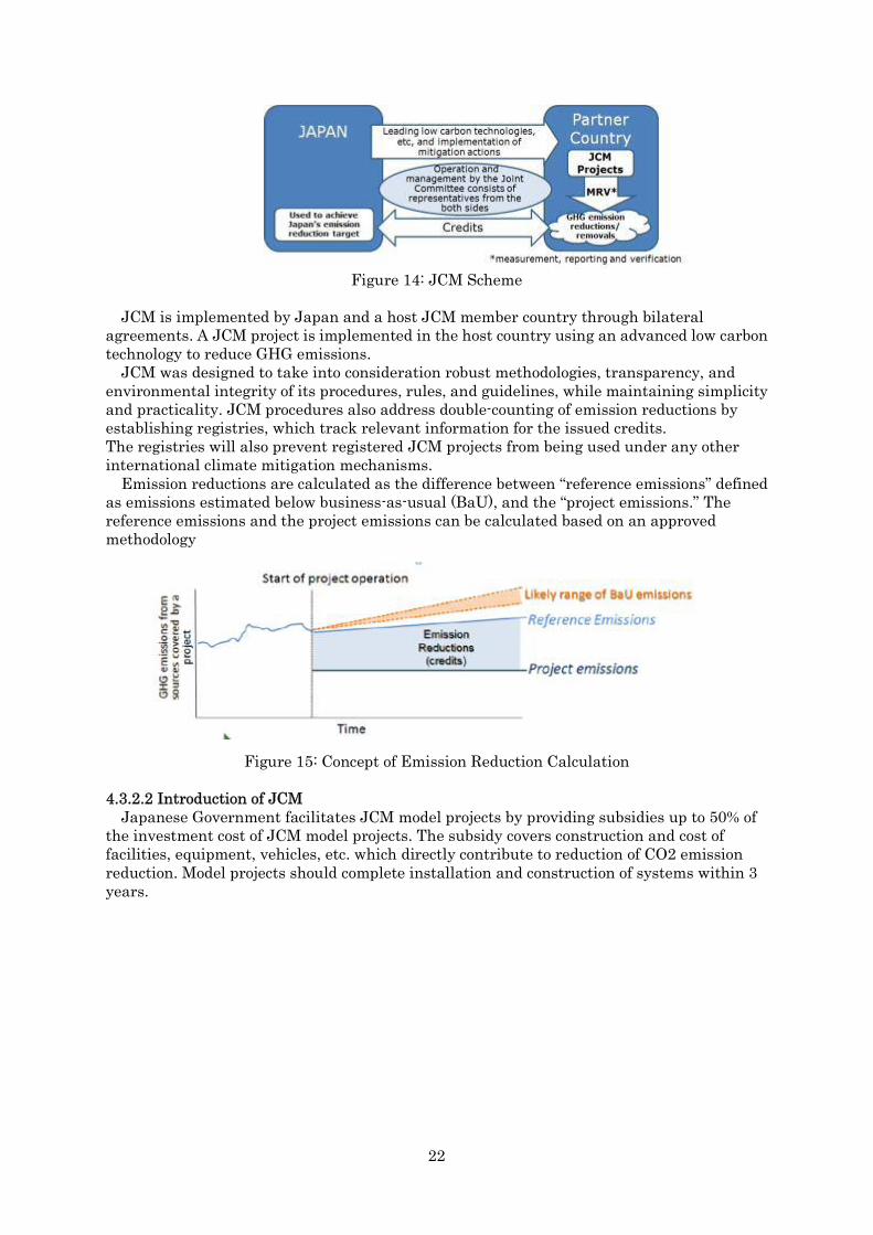
Figure 14: JCM Scheme
JCM is implemented by Japan and a host JCM member country through bilateral agreements. A JCM project is implemented in the host country using an advanced low carbon technology to reduce GHG emissions.
JCM was designed to take into consideration robust methodologies, transparency, and environmental integrity of its procedures, rules, and guidelines, while maintaining simplicity and practicality. JCM procedures also address double-counting of emission reductions by establishing registries, which track relevant information for the issued credits. The registries will also prevent registered JCM projects from being used under any other international climate mitigation mechanisms.
Emission reductions are calculated as the difference between “reference emissions” defined as emissions estimated below business-as-usual (BaU), and the “project emissions.” The reference emissions and the project emissions can be calculated based on an approved methodology
Figure 15: Concept of Emission Reduction Calculation
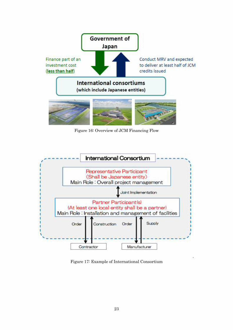
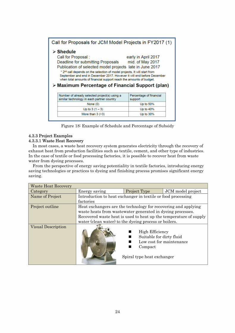
4.3.2.2 Introduction of JCM Japanese Government facilitates JCM model projects by providing subsidies up to 50% of
the investment cost of JCM model projects. The subsidy covers construction and cost of facilities, equipment, vehicles, etc. which directly contribute to reduction of CO2 emission reduction. Model projects should complete installation and construction of systems within 3 years.
23
Figure 16: Overview of JCM Financing Flow
Figure 17: Example of International Consortium
24
Figure 18: Example of Schedule and Percentage of Subsidy
4.3.3 Project Examples 4.3.3.1 Waste Heat Recovery
In most cases, a waste heat recovery system generates electricity through the recovery of exhaust heat from production facilities such as textile, cement, and other type of industries. In the case of textile or food processing factories, it is possible to recover heat from waste water from dyeing processes.
From the perspective of energy saving potentiality in textile factories, introducing energy saving technologies or practices to dyeing and finishing process promises significant energy saving.
Waste Heat RecoveryCategory Energy saving Project Type JCM model projectName of Project Introduction to heat exchanger in textile or food processing
factories Project outline Heat exchangers are the technology for recovering and applying
waste heats from wastewater generated in dyeing processes. Recovered waste heat is used to heat up the temperature of supply water (clean water) to the dyeing process or boilers.
Visual Description High Efficiency Suitable for dirty fluid Low cost for maintenance Compact
Spiral type heat exchanger

25
Operation and Features
The spiral type heat exchanger is suitable for recovering waste heat from fluids containing suspended solids such as hairs, threads and films. Therefore, for projects which try to recover waste heat from waste dyeing water in textile industries, the spiral type heat exchangers are recommended to be applied.
Eligibility Projects which recover waste heat from dyeing and finishing sections of textile and garment factories and food processing factories
Examples of Implementation
Textile or food processing factories
Overall Cost 240,000 USDGHG Emission reduction
1,833 ton/yearRecovered waste heat is used for preheating feed-water to boilers and dyeing machines so that reduce the fossil fuel consumption of boilers which provide steam for dyeing and finishing process.
Estimation Methodology on the GHG Emission Reduction
1.Terms and Definitions Textile dyeing and finishing: processes from pre-treatment to finishing in yarn and garment dyeing houses, including main procedures of pre-treatment, dyeing and finishing (washing/rinsing) of yarns or fabrics that is the chemical and physical treatments of yarn and fabrics by consuming heat (steam) Waste heat: heat energy from boiler exhaust air and/or waste water from dyeing machines
2. Summary of the Methodology Items SummaryGHG emission reduction measures
Recovered waste heat is used for preheating feed-water to boilers and dyeing machines which can reduce the fossil fuel consumption of boilers which provide steam for dyeing and finishing process.
Calculation of reference emissions
Reference emission is calculated based on the amount of waste energy/heat utilized, boiler efficiency and CO2 emission factor of the fossil fuel that is used in boilers for providing energy to the dyeing process. Conservative values of the parameters are used to ensure the reference emissions are lower than BaU emissions.
Calculation of project emissions
The project emission is calculated based on the electricity consumption of waste heat recovery system and CO2 emission factor of the electricity.
Monitoring parameters The following parameters need to be monitored. The temperature and the amount of feed-water for dyeing

26
This methodology is applicable to the projects of recovering heat from waste water generated in the processes of yarn and fabric dyeing in the textile factories or food processing factories.
3. Establishment of Reference Emissions The reference emission is the emission from the consumption of fossil fuel to gain the same amount of waste energy utilized.
4. Calculation of Reference Emissions ��� ���T��,� T��,� � W�� � F�,� �
1Ef � EF���,������
� 10��
RE�T�T��W�F�EfEF���,����
Reference emission [tCO2/p] Temperature of feed-water to the heat exchanger the project [degrees C] Temperature of feed-water from the heat exchanger to dyeing machines in the case the project [degrees C] The specific heat of water [kJ/kg degrees C] The amount of the feed-water in the project [t/p] Boiler efficiency [ratio] CO2 emission factor the fossil fuel that is used to provide energy for dyeing or other production processes[tCO2/TJ]
5. Calculation of Project Emissions Project emission is calculated based on the amount of electricity consumed by the waste heat recovery system and electricity CO2 emission factor.
PE� � EC��,� � EF����PE�EC��,�EF����
Project emissions [t CO2/p] Electricity consumption by the waste heat recovery system [MWh/p] CO2 emission factor of electricity [t CO2/MWh]
6. Calculation of Emissions Reduction ER� � RE� PE�RE�PE�
Reference emissions [t CO2/p] Project emissions [t CO2/p]
7. Data and Parameters Fixed Ex-ante Parameter Description of data SourceEf Boiler efficiency Factories
(100% is used for conservativeness)
EF���,���� CO2 emission factor of the fuel used for steam generation Natural gas: 54.3 t CO2/TJ (54.3–58.3) Coal:87.3 t CO2/TJ (87.3–101) Heavy oil:71.1 t CO2/TJ (71.1–75.5)
2006 IPCC Guidelines for National Greenhouse Gas Inventories. Table 1.4, Chapter 1, Volume 2.
EF���� CO2 emission factor of electricity In the case of grid: 0.508 tCO2/MWh In the case of captive power plant (diesel): 0.8 tCO2/MWh
In the case of grid (Combined margin emission factor for Philippine) (IGES's List of Grid Emission Factors)). In the case of diesel captive power plant (Table I.F.1,
machines and/or boiler in the project. The amount of electricity consumed by the waste heat recovery system.

27
Small Scale CDM Methodology: AMS I.F. ver.2)
4.3.3.2 Energy Efficient Boiler Boilers are important equipment in most industrial facilities and power plants. Boilers are
closed pressure vessels used to produce high pressure or low pressure steam or to produce hot water or heat for industrial or domestic use. Industrial steam boilers have many types of classifications. According to type of fuel used, there are coal fired boilers, oil fired boilers, gas fired boilers, biomass boilers and electric boilers and waster heat recovery boilers; when categorized according to steam pressure, there are low pressure boilers, medium pressure boilers and high pressure boilers.
Nippon Thermoener is one of the biggest boiler manufacturers in Japan and provides high efficiency boilers, such as steam boilers, hot-water heaters, and heat medium boilers, and other energy-saving and environmentally-friendly equipment and systems. As a boiler needs a large investment, the feasibility of replacing existing boilers with high efficiency boilers relies on the timing, condition of existing boilers and type of fuel the boiler uses.
Figure 19: Reference Scenario (without project)
Figure 20: Project Scenario
Without introduction of high efficiency boilers (HEB), boiler(s) with lower efficiency will continue to operate at multiple locations, thereby consuming high amounts of fossil fuel.
Employing HEBs through their rehabilitation or replacement will result in a reduction of fossil fuel consumption and related CO2 emissions.
Energy Efficient BoilerCategory Energy saving Project Type JCM model projectName of Project Introduction of energy-efficient boiler in factoriesProject outline Promote energy saving in factories by introducing energy efficient
boilers. Employing a boiler through their rehabilitation or replacement will result in a reduction of fossil fuel consumption
28
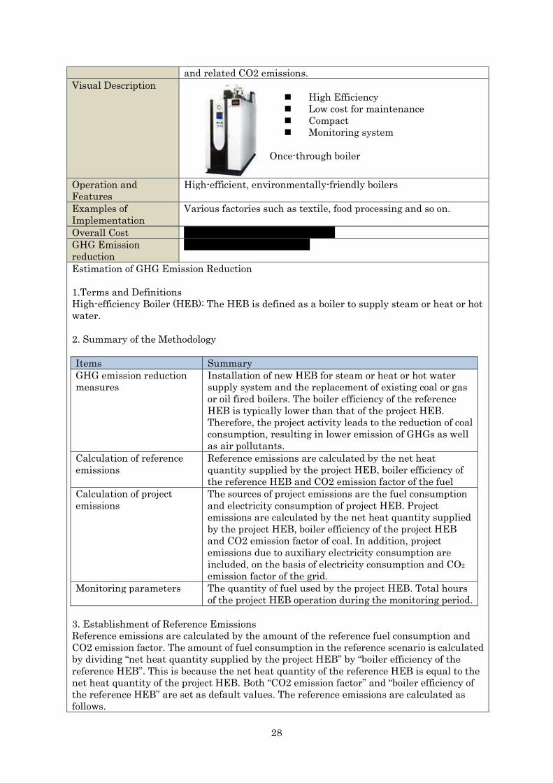
and related CO2 emissions.Visual Description
High Efficiency Low cost for maintenance Compact Monitoring system
Once-through boiler
Operation and Features
High-efficient, environmentally-friendly boilers
Examples of Implementation
Various factories such as textile, food processing and so on.
Overall Cost Approximately 270,000 US dollarGHG Emission reduction
Approximately 668 ton/year
Estimation of GHG Emission Reduction
1.Terms and Definitions High-efficiency Boiler (HEB): The HEB is defined as a boiler to supply steam or heat or hot water.
2. Summary of the Methodology
3. Establishment of Reference Emissions Reference emissions are calculated by the amount of the reference fuel consumption and CO2 emission factor. The amount of fuel consumption in the reference scenario is calculated by dividing “net heat quantity supplied by the project HEB” by “boiler efficiency of the reference HEB”. This is because the net heat quantity of the reference HEB is equal to the net heat quantity of the project HEB. Both “CO2 emission factor” and “boiler efficiency of the reference HEB” are set as default values. The reference emissions are calculated as follows.
Items SummaryGHG emission reduction measures
Installation of new HEB for steam or heat or hot water supply system and the replacement of existing coal or gas or oil fired boilers. The boiler efficiency of the reference HEB is typically lower than that of the project HEB. Therefore, the project activity leads to the reduction of coal consumption, resulting in lower emission of GHGs as well as air pollutants.
Calculation of reference emissions
Reference emissions are calculated by the net heat quantity supplied by the project HEB, boiler efficiency of the reference HEB and CO2 emission factor of the fuel
Calculation of project emissions
The sources of project emissions are the fuel consumption and electricity consumption of project HEB. Project emissions are calculated by the net heat quantity supplied by the project HEB, boiler efficiency of the project HEB and CO2 emission factor of coal. In addition, project emissions due to auxiliary electricity consumption are included, on the basis of electricity consumption and CO2emission factor of the grid.
Monitoring parameters The quantity of fuel used by the project HEB. Total hours of the project HEB operation during the monitoring period.

29
4. Calculation of Reference Emissions
RE� � FC�,� � NCV�,���� � η�,��� η��,���⁄ � EF���,����RE� Reference emissions during the period p [tCO2/p] FC�,� Quantity of fuel used by the project HEB during the period p [t/p]NCV�,����,� Net caloric value of the fuel used by the project HEB during the period p
[GJ/t] η��,��� Boiler efficiency of the reference HEB [-]η�,��� Boiler efficiency of the project HEB [-]EF���,���� CO2 emission factor of coal [tCO2/GJ]
5. Calculation of Project Emissions Project emissions are calculated by “the amount of the project fuel consumption” and “CO2 emission factor of the fuel”. Both “CO2 emission factor” and “boiler efficiency of the project and reference HEB” are set as default values. Additionally, electricity consumption of the project HEB is calculated in a conservative manner. Therefore, the project emissions are calculated as follows.
PE� � FC�,� � EF���,���� � EC�,� � EF���,���� PE� Project emissions during the period y [tCO2/p]PC�,� Quantity of fuel used by the project HEB during the period p [t/p]EF���,���� CO2 emission factor of fuel [tCO2/GJ]EC�,� Electricity consumption of the project HEB during the period p [MWh/y]EF���,���� CO2 emission factor of the grid electricity consumed by the project HEB
[tCO2/MWh]
��� � RPC��,��� � 1000 � ����EC� Electricity consumption of the project HEB during the period p [MWh/p]RPC��,��� Rated power consumption of the project HEB [kW]HMP� Total hours of the project HEB operation during the monitoring period p [h/p]
6. Calculation of Emissions Reduction
ER� � RE� PE�RE� Reference emissions [t CO2/p]PE� Project emissions [t CO2/p]
7. Data and Parameters Fixed Ex-ante The source of each data and parameter fixed ex ante is listed as below.
Parameter Description of data Source�,��� Boiler efficiency of the reference HEB
calculated from published information and measured data
Actual measured values.
η�,��� Boiler efficiency of the project HEBcalculated from published information and measured data
Actual measured values.
�����,���� CO2 emission factor of fuelNatural gas:54.3 t CO2/TJ (54.3–58.3)Coal:87.3 t CO2/TJ (87.3–101) Heavy oil:71.1 t CO2/TJ (71.1–75.5)
2006 IPCC Guidelines for National Greenhouse Gas Inventories. Table 1.4, Chapter 1, Volume 2.

30
�����,���� CO2 emission factor of the grid electricity consumed by the project HEB. In the case of grid: 0.508 tCO2/MWh In the case of captive power plant (diesel): 0.8 tCO2/MWh
The most recent value available at the time of validation is applied and fixed for the monitoring period thereafter. In the case of grid (Combined margin emission factor for Philippine) (IGES's List of Grid Emission Factors)). In the case of diesel captive power plant (Table I.F.1, Small Scale CDM Methodology: AMS I.F. ver.2).
RPC��,��� Rated power consumption of the project HEB
Catalog value provided by the manufacturer of the project HEB
4.3.3.3 Issues regarding JCM Project implementation The following points need to be determined to implement a model project. These are also to
be seen as challenges to realize JCM model projects. Determination of a representative project participant Confirmation of local participants and their decision Conclusion of international consortium agreement Confirmation of the budget adjustment of local participants Financing plan Profitability analysis Project schedule Confirmation of law, regulations and licenses
4.3.4 Future prospects 4.3.4.1 Expansion of JCM Project
JCM model project supports up to 50% of initial investment costs of projects, which promote renewable energy or energy saving so that contributes to reduction of CO2 emissions.
However, awareness and recognition of JCM is still insufficient in Vietnam. Therefore, it is important to introduce JCM scheme and related technologies to different players such as industrial parks, hotels, hospitals, schools, and public buildings with huge energy consumption.
4.3.4.2 Trend of JCM JCM projects require various stakeholders’ involvement. Thus, in order to expand and
efficiently implement JCM projects, it is necessary to attract as many players as possible to join and benefit from JCM. From the perspective of financing, various business models are now applicable to JCM such as ESCO and JCM is evolving to a mechanism which is flexible and benefits various and multi-level players in both the host country and Japan. In HCMC, Energy Conservation Centre (ECC) and Vietnam Textile Association (VITAS) are the key players to expand energy saving project through JCM.
Chapter 5 Promotion of Public-Private Partnerships (PPP) Osaka City has been supporting low carbon development in Asian cities including HCMC
working with MOE, GEC and private companies. In July, 2011, Osaka City and HCMC signed an MOU on cooperation in the field of economic, environment conservation and water supply and water management.
Under the MOU, HCMC received extensive support from Osaka City, in collaboration with MOE, International Cooperation Agency (JICA), private companies, and research institutes to formulate projects, training programs and dispatch experts.
In October 2013, Osaka and HCMC exchanged an MOU on the development into a low
31
carbon city, using the agreement signed between Japan and Vietnam regarding JCM as an opportunity for collaboration. The collaboration between the two cities helped HCMC complete its climate change action plan. And other projects such as JCM, policy dialogues between the mayors of two cities were implemented as well.
In 2013, the chairman of HCMC People’s Committee visited Osaka including a waste incineration facility and then in 2014, Osaka City and HCMC Natural Resources and Environment Bureau had a policy dialogue to discuss cooperation in the field of waste and waste water treatment.
In the approved CCAP for 2017~2020, HCMC specified 10 priority sectors such as urban planning, energy, transportation, industry, water treatment and waste treatment as they tackle climate change. For setting GHG emission reduction targets, Osaka has supported HCMC by applying a climate change simulation model (Asian-Pacific Integrated Model (AIM)) in cooperation with National Institute for Environmental Studies.
So far, 6 JCM projects have been launched in HCMC by Japan companies. Among the projects, 3 projects have already been registered as JCM projects.
To support low carbon development in Asian cities including HCMC through PPP, in 2016, Osaka City launched “Team OSAKA Network”, which consists of companies, organizations, located in Osaka and other parts of Kansai region. As of January 2018, the number of members of the Team reached 130.
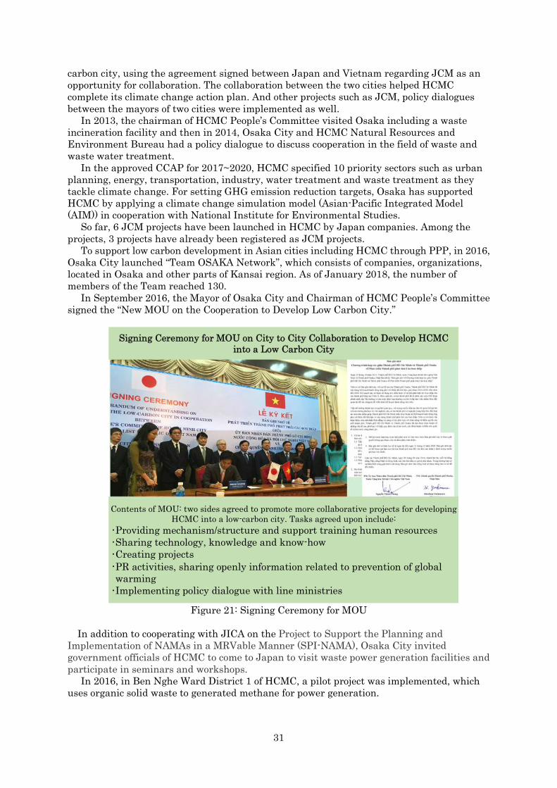
In September 2016, the Mayor of Osaka City and Chairman of HCMC People’s Committee signed the “New MOU on the Cooperation to Develop Low Carbon City.”
Figure 21: Signing Ceremony for MOU
In addition to cooperating with JICA on the Project to Support the Planning and Implementation of NAMAs in a MRVable Manner (SPI-NAMA), Osaka City invited government officials of HCMC to come to Japan to visit waste power generation facilities and participate in seminars and workshops.
In 2016, in Ben Nghe Ward District 1 of HCMC, a pilot project was implemented, which uses organic solid waste to generated methane for power generation.
Signing Ceremony for MOU on City to City Collaboration to Develop HCMC into a Low Carbon City
Contents of MOU: two sides agreed to promote more collaborative projects for developing HCMC into a low-carbon city. Tasks agreed upon include:
•Providing mechanism/structure and support training human resources •Sharing technology, knowledge and know-how •Creating projects •PR activities, sharing openly information related to prevention of global warming •Implementing policy dialogue with line ministries

32
The study itself is one of the feasibility studies realized under the collaboration of two cities using JCM scheme financed by MOE. This study provided HCMC potential energy saving JCM projects which can be actions in HCMC’s action plan.
Figure 22: Policy Dialogue

33
Chapter 6 Workshops, Trainings and Meetings 6.1 Overview
Under the city to city collaboration, the project supported the development of action plan on the energy saving in textile factories. At the same time, energy auditing to factories was conducted to define energy saving potentiality of the textile factories in HCMC.
Table 24: Project Activities Activities Date DescriptionKick off meeting in Osaka
25th May ・Kick off meeting with co-implementers and Osaka City to implement the study
The 1st field survey in HCMC
3rd – 6th
July ・Meeting and discussions with DONRE, ECC, VITAS and
textile factories
The 1st city to city collaboration workshop in Kawasaki
24th – 29th
July ・Visit Osaka City and technology providers facility (heat
exchanger and boiler factories) ・Visit the waste power generation facilities in Kawasaki
city ・Share the issues on low carbon city development in
HCMC The 2nd filed survey in HCMC
25th – 29th
September ・ Organize the 1st workshop in HCMC ・Implement energy auditing in the factories
Training in Japan
20th October ・Meeting and discussions with officers from DONRE on future projects for CCAP
The 3rd field survey in HCMC
19th – 25th
January ・Organize a the 2nd workshop in HCMC to report the
result of the study and discuss relate issues
The 2nd city to city collaboration workshop in Tokyo
29th – 31st
January ・Report the progress of the study ・Meeting and discussions with factory regarding next
actions
6.2 The 1st Field Survey The first field survey was conducted from July 3rd to 6th 2017 in HCMC. The study team
had meetings with HCMC Climate Change Bureau, ECC and VITAS to explain the study and JCM and ask for their cooperation for the study. The team also visited textile factories to determine target factories for the study.
Figure 23: Kick-off Meeting
6.3 The 1st City to City Collaboration Workshop Organized by MOE in Japan (July) 6.3.1 Overview
The workshop was organized by MOE on 27~28 July, 2017 in Kawasaki, Japan.
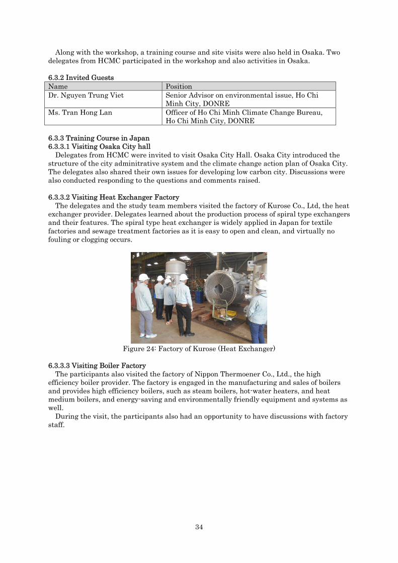
34
Along with the workshop, a training course and site visits were also held in Osaka. Two delegates from HCMC participated in the workshop and also activities in Osaka.
6.3.2 Invited Guests Name PositionDr. Nguyen Trung Viet Senior Advisor on environmental issue, Ho Chi
Minh City, DONRE Ms. Tran Hong Lan Officer of Ho Chi Minh Climate Change Bureau,
Ho Chi Minh City, DONRE
6.3.3 Training Course in Japan 6.3.3.1 Visiting Osaka City hall
Delegates from HCMC were invited to visit Osaka City Hall. Osaka City introduced the structure of the city adminitrative system and the climate change action plan of Osaka City. The delegates also shared their own issues for developing low carbon city. Discussions were also conducted responding to the questions and comments raised.
6.3.3.2 Visiting Heat Exchanger Factory The delegates and the study team members visited the factory of Kurose Co., Ltd, the heat
exchanger provider. Delegates learned about the production process of spiral type exchangers and their features. The spiral type heat exchanger is widely applied in Japan for textile factories and sewage treatment factories as it is easy to open and clean, and virtually no fouling or clogging occurs.
Figure 24: Factory of Kurose (Heat Exchanger)
6.3.3.3 Visiting Boiler Factory The participants also visited the factory of Nippon Thermoener Co., Ltd., the high
efficiency boiler provider. The factory is engaged in the manufacturing and sales of boilers and provides high efficiency boilers, such as steam boilers, hot-water heaters, and heat medium boilers, and energy-saving and environmentally friendly equipment and systems as well.
During the visit, the participants also had an opportunity to have discussions with factory staff.

35
Figure 25: Discussions at the Boiler Factory
6.4 The 2nd Field Survey 6.4.1 Overview
The 2nd field survey to HCMC was conducted on 25th to 29th September 2017. During the survey, a workshop was held in the conference room of DONRE. The
participants for the workshop were the delegates of HCMC Climate Change Bureau, ECC, and VITAS from HCMC and Osaka City, Oriental Consultant, Yuko-Keiso Co., Ltd., Japan Textile Professional Engineer Center, Nippon Thermoener Co., Ltd and Hitachi Vietnam from Japan. Energy auditing of the factories were also conducted during the survey.
Figure 26: Workshop and Energy Auditing

36
The agenda of the workshop was as follows.
Workshop on the Promotion of Low Carbon Development in Ho Chi Minh City under the City to City Cooperation between Ho Chi Minh and Osaka
Jointly Organized by Ho Chi Minh City (HCMC), the Osaka City and Oriental Consultants
Date: September 25th, 2017, 8:30-11:30 Venue: Meeting Room of DONRE Language: Vietnamese-Japanese consecutive interpretation
The objectives of the workshop were to: 1) share information and knowledge on energy saving practices, especially, in textile
industry involving the introduction of JCM energy projects 2) share information on energy saving potentiality in the industry sector of Ho Chi Minh
City for potential JCM energy projects in the future 3) share information on the progress of low carbon city development in Ho Chi Minh City
and issues in association with the implementation of Ho Chi Minh Climate Change Action Plan (CCAP), for which Osaka City would provide support.
Programme
8:30-8:45 <Opening Remarks> “Opening Remarks” by Department of Natural Resources and
Environment (DONRE) “Opening Remarks” by Director, Oriental Consultants
8:45-9:45
<Presentation > “Outline of energy saving feasibility study in this fiscal year and
introduction to JCM energy projects” by Oriental Consultants “Situation and prospects in textile industry in HCMC”
by Vietnam Textile and Apparel Association “Energy saving potential in the industrial sector in HCMC”
by Energy Conservation Center 9:45 -10:00 <Questions and Answers>
10:00-10:20 Photo and Break
10:20-11:10 <Presentation > “Capacity building on the CCAP” by Osaka City “Progress on low carbon development and prospects of activities
based on CCAP” by DONRE 11:10-11:20 <Questions and Answers>
11:20-11:30 <Closing Remark> “Closing Remark”
by Osaka City
6.6 Training in Japan organized by Osaka City (October) 6.6.1 Overview
The training course was conducted on the 20th of October 2017 in Osaka. Osaka city presented about the collection of data from private conpanies regarding GHG emission and activities of raising public’ awareness of climate change. HCMC also gave a presentation on the activities of developing GHG emission invenstory in HCMC.
6.6.2 Invited Guests Name PositionDr. Nguyen Trung Viet Senior Advisor on environmental issue,

37
HCMC DONREMr. Nguyen Huy Phuong Officer Ho Chi Minh Climate Change
Bureau, HCMC DONRE
6.6.3 Training Course in Japan HCMC shared the following information with the participants.
The city is promoting 3 projects based on the CCAP. 1. Research and studies about CO2 emission
(Not funded by HCMC) 2. Projects funded by HCMC
(Most are small projects with a budget less than 10 Million JPY) 3. Projects implemented by private companies
(This kind of projects are planned to be implemented cooperating with donors and private companies.)
Regarding the first two types, DONRE prepares a plan for each year and submits it to the committee for approval. For the third type, project lists need to be prepared in coordination with other related bureaus.
The projects that need to be implemented in the future are as follows. 1. Green buildings 2. Traffic congestion mitigation 3. Saigon river tourism development 4. Subway projects supported by Japan
In addition, a technical manual developed under the SPI-NAMA will be available for private companies by 2018.
Figure 27: Discussions during the Training in Japan
6.7 The 3rd Field Survey 6.7.1 Overview
The survey was conducted on the 21st ~24th of January, 2018. The main purpose of the survey was to organize a workshop to report the result of the study to the stakeholders and discuss with factories the next actions toward JCM model projects. The agenda of the workshop is shown below.
2nd Workshop on the Promotion of Low Carbon Development in Ho Chi Minh City under the City to City Cooperation between Ho Chi Minh and Osaka
Jointly Organized by Ho Chi Minh City (HCMC), the Osaka City and Oriental Consultants.
Date: January 22th, 2018, 9:00-11:20 Venue: Meeting Room of DONRE Language: Vietnamese-Japanese consecutive interpretation
The objectives of the workshop were to: 1) share information and knowledge on energy saving practices, especially, in textile
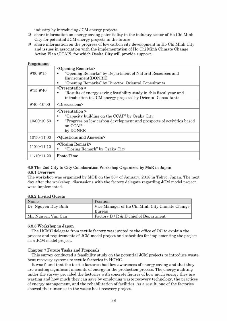
38
industry by introducing JCM energy projects 2) share information on energy saving potentiality in the industry sector of Ho Chi Minh
City for potential JCM energy projects in the future 3) share information on the progress of low carbon city development in Ho Chi Minh City
and issues in association with the implementation of Ho Chi Minh Climate Change Action Plan (CCAP), for which Osaka City will provide support.
Programme
9:00-9:15 <Opening Remarks> “Opening Remarks” by Department of Natural Resources and
Environment(DONRE) “Opening Remarks” by Director, Oriental Consultants
9:15-9:40 <Presentation > “Results of energy saving feasibility study in this fiscal year and
introduction to JCM energy projects” by Oriental Consultants 9:40 -10:00 <Discussions>
10:00-10:50
<Presentation > “Capacity building on the CCAP” by Osaka City “Progress on low carbon development and prospects of activities based
on CCAP” by DONRE
10:50-11:00 <Questions and Answers>
11:00-11:10 <Closing Remark> “Closing Remark” by Osaka City
11:10-11:20 Photo Time
6.8 The 2nd City to City Collaboration Workshop Organized by MoE in Japan 6.8.1 Overview The workshop was organized by MOE on the 30th of January, 2018 in Tokyo, Japan. The next day after the workshop, discussions with the factory delegate regarding JCM model project were implemented.
6.8.2 Invited Guests Name PositionDr. Nguyen Duy Binh Vice Manager of Ho Chi Minh City Climate Change
Bureau Mr. Nguyen Van Can Factory B / R & D chief of Department
6.8.3 Workshop in Japan The HCMC delegate from textile factory was invited to the office of OC to explain the
process and requirements of JCM model project and schedules for implementing the project as a JCM model project.
Chapter 7 Future Tasks and Proposals This survey conducted a feasibility study on the potential JCM projects to introduce waste
heat recovery systems to textile factories in HCMC. It was found that the textile factories had low awareness of energy saving and that they
are wasting significant amounts of energy in the production process. The energy auditing under the survey provided the factories with concrete figures of how much energy they are wasting and how much they can save by employing waste recovery technology, the practices of energy management, and the rehabilitation of facilities. As a result, one of the factories showed their interest in the waste heat recovery project.

39
The survey implied that in order to implement JCM projects to the industry sector in HCMC and expand them in Vietnam, it is necessary to select factories with financial capacity and conduct energy auditing in the factories to help them understand their energy management condition and ways of saving energy.
Another issue that was found through the survey is that JCM still has low name-recognition among private companies in Vietnam even after 5 years since the country has become JCM member state. JCM’s profile among private companies in HCMC is expected to rise through introducing
successful cases and merits of JCM by continuously utilizing the networks of VITAS and ECC. During the survey, the study team was able to work with textile factories through the
VITAS and VITAS’s awareness of JCM scheme and its benefits also increased through workshops held in HCMC. The energy saving action plan developed through the survey translated the CCAP into
specific energy saving project activities such as waste heat recovery projects and high efficiency boiler introduction projects. The action plan and its expansion to other technologies are expected to help the dissemination of Japanese technologies in HCMV through JCM scheme.