Embed Size (px)
Citation preview
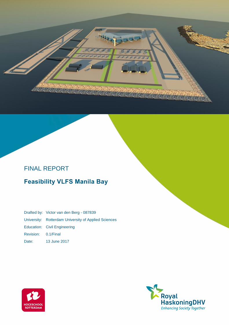
FINAL REPORT
Feasibility VLFS Manila Bay
Drafted by: Victor van den Berg - 087839
University: Rotterdam University of Applied Sciences
Education: Civil Engineering
Revision: 0.1/Final
Date: 13 June 2017

13 June 2017 FINAL REPORT i
(This page is intentionally left blank)

13 June 2017 FINAL REPORT ii
HASKONINGDHV NEDERLAND B.V.
George Hintzenweg 85
3068 AX Rotterdam
Netherlands
Maritime & Aviation
Trade register number: 56515154
+31 88 348 90 00
+31 10 209 44 26
royalhaskoningdhv.com
T
F
E
W
Document title: Final Report
Document short title: Feasibility VLFS Manila Bay
Revision: 0.1/Final
Date:
13 June 2017
Author(s):
Victor van den Berg
Drafted by: V. van den Berg
Checked by: R. Stive
Date/initials Check: June 2nd
, 2017 RJS
Approved by: R. Stive
Date/initials Check: June 2nd
, 2017 RJS
Disclaimer
No part of these specifications/printed matter may be reproduced and/or published by print, photocopy, microfilm or by
any other means, without the prior written permission of HaskoningDHV Nederland B.V.; nor may they be used,
without such permission, for any purposes other than that for which they were produced. HaskoningDHV Nederland
B.V. accepts no responsibility or liability for these specifications/printed matter to any party other than the persons by
whom it was commissioned and as concluded under that Appointment. The integrated QHSE management system of
HaskoningDHV Nederland B.V. has been certified in accordance with ISO 9001:2015, ISO 14001:2015 and OHSAS
18001:2007.

13 June 2017 FINAL REPORT iii
(This page is intentionally left blank)

13 June 2017 FINAL REPORT iv
Preface
The last phase of the Bachelor study civil engineering at the Rotterdam University of Applied Sciences is a
thesis project. This thesis project tests the expertise of the graduation students weather they are ready for
the business community. Besides, the graduation students have to satisfy to the given competences of the
Rotterdam University of Applied Sciences.
The subject of this thesis is provided by Royal HaskoningDHV (RHDHV). This is a Dutch engineering
company, acting all over the world in more than 100 countries. In over 135 years, RHDHV has grown to a
professional and international operating company. Approximately 6000 people are working for Royal
HaskoningDHV; they deliver consultancy and engineering services. Royal HaskoningDHV has
approximately 100 offices divided over 35 countries presented all over the world. The company is
specialized in Aviation, Buildings, Energy, Industry, Infrastructure, Maritime, Mining, Rural developments,
Urban development and Water. The services contribute to a better and sustainable society, this resulted in
their slogan; “Enhancing Society Together”.
In the period of February until June we, Sjaak Bijl and Victor van den Berg worked on this thesis project.
We have experienced this graduation as interesting and educational. We have learned about the design of
floating structures, hydrodynamic conditions, airports and land reclamation projects. Beginning this thesis
project we had little knowledge regarding the aspects of the wave theory, which was a very important item
during this graduation project. However, during the preparation- and feasibility phase we have learned a
lot about this subject. The feasibility phase in particular was most challenging due to the limited expertise
of the influences by a landing airplane and waves at a Very Large Floating Structure. We are satisfied with
the results of our thesis and the knowledge we have gained.
We would especially like to thank our supervisor of Royal HaskoningDHV, Ronald Stive and our
Rotterdam University of Applied Sciences supervisor; Harry Dommershuijzen, for their guidance and
advices during this thesis project. Moreover, we would thank all colleagues within Royal HaskoningDHV
who helped and guided us during the graduation process. In particular: Dirk-Jan Peters, Kasay Asmerom,
Perry Groenewegen, Michiel Smits and Teodora Cristutiu. Last but not least we would like to thank the
senior airport development advisor of NACO, Hein Baijer for his provided information about designing an
airport and the review on documents.
Sjaak Bijl & Victor van den Berg
Rotterdam, 13-06-2017

13 June 2017 FINAL REPORT v
(This page is intentionally left blank)
13 June 2017 FINAL REPORT vi
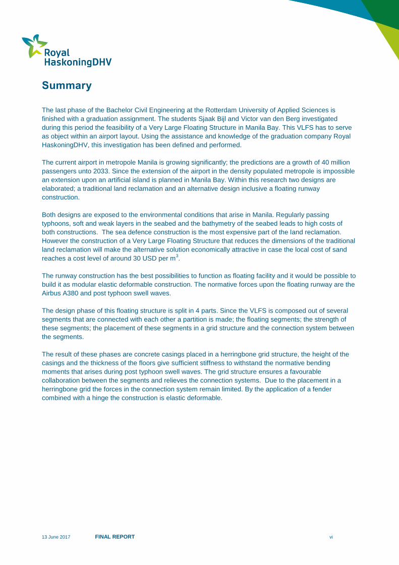
Summary
The last phase of the Bachelor Civil Engineering at the Rotterdam University of Applied Sciences is
finished with a graduation assignment. The students Sjaak Bijl and Victor van den Berg investigated
during this period the feasibility of a Very Large Floating Structure in Manila Bay. This VLFS has to serve
as object within an airport layout. Using the assistance and knowledge of the graduation company Royal
HaskoningDHV, this investigation has been defined and performed.
The current airport in metropole Manila is growing significantly; the predictions are a growth of 40 million
passengers unto 2033. Since the extension of the airport in the density populated metropole is impossible
an extension upon an artificial island is planned in Manila Bay. Within this research two designs are
elaborated; a traditional land reclamation and an alternative design inclusive a floating runway
construction.
Both designs are exposed to the environmental conditions that arise in Manila. Regularly passing
typhoons, soft and weak layers in the seabed and the bathymetry of the seabed leads to high costs of
both constructions. The sea defence construction is the most expensive part of the land reclamation.
However the construction of a Very Large Floating Structure that reduces the dimensions of the traditional
land reclamation will make the alternative solution economically attractive in case the local cost of sand
reaches a cost level of around 30 USD per m3.
The runway construction has the best possibilities to function as floating facility and it would be possible to
build it as modular elastic deformable construction. The normative forces upon the floating runway are the
Airbus A380 and post typhoon swell waves.
The design phase of this floating structure is split in 4 parts. Since the VLFS is composed out of several
segments that are connected with each other a partition is made; the floating segments; the strength of
these segments; the placement of these segments in a grid structure and the connection system between
the segments.
The result of these phases are concrete casings placed in a herringbone grid structure, the height of the
casings and the thickness of the floors give sufficient stiffness to withstand the normative bending
moments that arises during post typhoon swell waves. The grid structure ensures a favourable
collaboration between the segments and relieves the connection systems. Due to the placement in a
herringbone grid the forces in the connection system remain limited. By the application of a fender
combined with a hinge the construction is elastic deformable.

13 June 2017 FINAL REPORT vii
(This page is intentionally left blank)
13 June 2017 FINAL REPORT viii
Samenvatting
De laatste fase van de Bachelor opleiding Civiele techniek aan de hogeschool Rotterdam wordt afgesloten
met een afstudeeropdracht. De afstudeerstudenten Victor van den Berg en Sjaak Bijl hebben gedurende
deze periode onderzoek gedaan naar de haalbaarheid van een Very Large Floating Structure (hele grote
drijvende constructie) in Manila Bay. De VLFS dient hierbij te fungeren als faciliteit binnen de plattegrond
van een vliegveld. Met hulp en kennis van het afstudeerbedrijf, Royal HaskoningDHV, is het onderzoek
gedefinieerd en ingevuld.
Het huidige vliegveld in de metropool Manila groeit significant; de voorspelling is een groei van 40 miljoen
passagiers in 2033. Aangezien het vliegveld gelegen is in een dichtbevolkte metropool met weinig ruimte,
is het onmogelijk om een uitbreiding op land te realiseren. Binnen dit afstudeeronderzoek worden hierbij
de opties van een traditionele landaanwinning en een alternatief ontwerp, inclusief een drijvende
landingsbaan overwogen.
Beide ontwerpen dienen hierbij bestand te zijn tegen de lokale omstandigheden van Manila. Regelmatige
passerende cyclonen, de aanwezige zwakke ondergrond en de diepteligging van zeebodem leiden hierbij
tot hoge kosten voor beide constructies. De zeewering binnen de landaanwinning kan gezien worden als
de hoogste kostenpost. De constructie van een VLFS leidt tot kleinere afmetingen van de traditionele
landaanwinning, hierbij wordt de alternatieve oplossing economisch aantrekkelijk indien de lokale
zandprijs een waarde bereikt van 30 USD per m3.
De landingsbaan kan het best als een drijvende faciliteit worden toegepast, het is mogelijk om dit op te
bouwen als een modulair elastische vervormbare constructie. Maatgevende belastingen op de drijvende
constructie zijn de Airbus A380 en de deining golven, veroorzaakt vanuit een cycloon.
Het ontwerpproces van de VLFS is opgedeeld in 4 gedeeltes. Aangezien de VLFS is opgedeeld in
verscheidene segmenten, die allemaal gekoppeld aan elkaar worden, is er een onderverdeling gemaakt;
grootte van de segmenten, sterkte van de segmenten, plaatsing segmenten in een bepaald raster en het
type verbindingssysteem.
Het resultaat van deze fases is dat de betonnen kokers in een visgraat raster structuur worden toegepast.
De hoogte van de betonnen kokers en de dikte van de vloeren geven voldoende stijfheid om de
maatgevende buigende momenten door deining golven (veroorzaakt uit een cycloon) te kunnen opnemen.
De rasterstructuur zorgt voor een gunstige samenwerking tussen de segmenten en verlichten de
tussenliggende verbindingen. Vanwege de plaatsing in een visgraat structuur, blijven krachten in de
verbindingen blijven beperkt. Bij het toepassen van een fender gecombineerd met een scharnier, reageert
de constructie elastisch vervormbaar.
13 June 2017 FINAL REPORT 1
Contents
1 Introduction 4
1.1 Project Definition 4
1.2 Project goal 5
1.3 Project approach 6
2 Literature Study 7
3 Statement of Requirements 8
Stakeholders 8 3.1
Requirements 8 3.2
4 Local conditions 9
4.1 Introduction 9
4.2 Environmental conditions 10
4.2.1 Chart datum 10
4.2.2 Climate 10
4.2.3 Bathymetry 11
4.3 Geotechnical conditions 11
4.3.1 Soil profile 11
4.3.2 Seismic activity 11
4.4 Hydraulic conditions 12
5 Traditional land reclamation 13
Footprint land reclamation 13 5.1
Activities 13 5.2
5.2.1 Dredging 13
5.2.2 Sea defence 14
5.2.3 Sand fill 14
Total costs 15 5.3
6 Airport design 16
Floating facilities 16 6.1
Other facilities 17 6.2
Floating northern runway 17 6.3
6.3.1 Build-up 17
6.3.2 Connection artificial island 18
Layout hybrid alternative design 19 6.4
13 June 2017 FINAL REPORT 2
7 Structural Analysis 20
Elastic deformable construction 20 7.1
Load combinations 21 7.2
7.2.1 Waves 21
7.2.2 Airplane 23
Schematization structure 23 7.3
8 Design floating segments 24
Cross section shape 24 8.1
Material 24 8.2
9 Grid structure 25
Placement segments 25 9.1
Explanation principle grid 25 9.2
Requisite pattern 26 9.3
9.3.1 Grid structure 26
9.3.2 Connections 27
Chosen herringbone structure 29 9.4
10 Connection system 31
Longlist 31 10.1
10.1.1 Boundary conditions 31
10.1.2 Alternatives 31
10.1.3 Chosen final system 31
Final connection system 33 10.2
10.2.1 Cross section 33
10.2.2 Details 34
11 Concrete casing 35
Build-up segments 35 11.1
Stiffness segments 35 11.2
12 Total costs VLFS 36
13 Cost comparison 37

13 June 2017 FINAL REPORT 3
14 Conclusion 40
15 Recommendations 41
Introduction 41 15.1
Design aspects 41 15.2
Optimizations 42 15.3
16 Bibliography 43
Separately provided reports
In addition to the final thesis report, the following interim deliverables and documents for
the University of Rotterdam are separately provided.
Interim deliverables:
A. Basis of Design
B. Study Very Large Floating structures
C. Airport Design
D. Traditional land reclamation and costs
E. Structural Analysis
F. Concept design floating segment
G. Concept design grid structure
H. Connection system
I. Concrete casing
J. Cost comparison
Appendices
Appendix A1 Bathymetry Project Site
Appendix A2 Typical cross section seabed
Appendix C2 Reference design of Manila Bay International Airport
Appendix C3 Floating structure
Appendix H1 Longlist Connection Systems
Appendix H2 Final Design Connection System
Appendix J1 Cross section Traditional land reclamation + Hybrid alternative design
13 June 2017 FINAL REPORT 4
1 Introduction
1.1 Project Definition
Manila is the capital of the Philippines and its population is growing significantly. The coming years there
is an urgent need to extend the airport capacity. Due to limited space on existing land, the option of land
reclamation or floating should be considered.
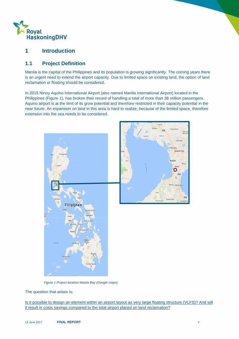
In 2015 Ninoy Aquino International Airport (also named Manila International Airport) located in the
Philippines (Figure 1), has broken their record of handling a total of more than 38 million passengers.
Aquino airport is at the limit of its grow potential and therefore restricted in their capacity potential in the
near future. An expansion on land in this area is hard to realize, because of the limited space, therefore
extension into the sea needs to be considered.
The question that arises is;
Is it possible to design an element within an airport layout as very large floating structure (VLFS)? And will
it result in costs savings compared to the total airport placed on land reclamation?
Figure 1 Project location Manila Bay (Google maps)
13 June 2017 FINAL REPORT 5
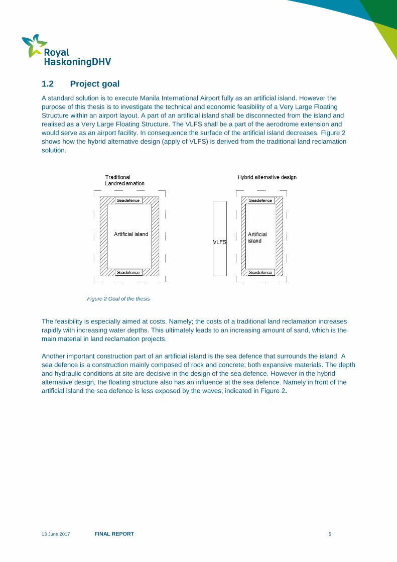
1.2 Project goal
A standard solution is to execute Manila International Airport fully as an artificial island. However the
purpose of this thesis is to investigate the technical and economic feasibility of a Very Large Floating
Structure within an airport layout. A part of an artificial island shall be disconnected from the island and
realised as a Very Large Floating Structure. The VLFS shall be a part of the aerodrome extension and
would serve as an airport facility. In consequence the surface of the artificial island decreases. Figure 2
shows how the hybrid alternative design (apply of VLFS) is derived from the traditional land reclamation
solution.
The feasibility is especially aimed at costs. Namely; the costs of a traditional land reclamation increases
rapidly with increasing water depths. This ultimately leads to an increasing amount of sand, which is the
main material in land reclamation projects.
Another important construction part of an artificial island is the sea defence that surrounds the island. A
sea defence is a construction mainly composed of rock and concrete; both expansive materials. The depth
and hydraulic conditions at site are decisive in the design of the sea defence. However in the hybrid
alternative design, the floating structure also has an influence at the sea defence. Namely in front of the
artificial island the sea defence is less exposed by the waves; indicated in Figure 2.
Figure 2 Goal of the thesis
13 June 2017 FINAL REPORT 6
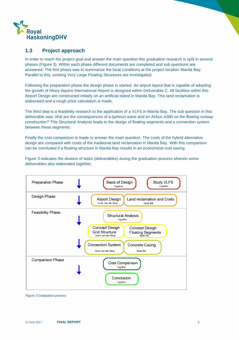
1.3 Project approach
In order to reach the project goal and answer the main question this graduation research is split in several
phases (Figure 3). Within each phase different documents are completed and sub questions are
answered. The first phase was to summarize the local conditions at the project location Manila Bay.
Parallel to this, existing Very Large Floating Structures are investigated.
Following the preparation phase the design phase is started. An airport layout that is capable of adopting
the growth of Ninoy Aquino International Airport is designed within Deliverable C. All facilities within this
Airport Design are constructed initially on an artificial island in Manila Bay. This land reclamation is
elaborated and a rough price calculation is made.
The third step is a feasibility research to the application of a VLFS in Manila Bay. The sub question in this
deliverable was; Wat are the consequences of a typhoon wave and an Airbus A380 on the floating runway
construction? This Structural Analysis leads to the design of floating segments and a connection system
between these segments.
Finally the cost comparison is made to answer the main question. The costs of the hybrid alternative
design are compared with costs of the traditional land reclamation in Manila Bay. With this comparison
can be concluded if a floating structure in Manila Bay results in an economical cost saving.
Figure 3 indicates the division of tasks (deliverables) during the graduation process wherein some
deliverables also elaborated together.
Figure 3 Graduation process
13 June 2017 FINAL REPORT 7
2 Literature Study
Due to a growing world population space in and around several metropoles is limited; the construction of
artificial islands is widely applied to create usable areas. Also floating constructions can serve as
extension of land to facilitate activities like housing, storage and recreation. Within this preparation phase
several constructions/projects were found that are built on artificial island, however extension of land by
means of Very Large Floating Structures is not much applied so far.
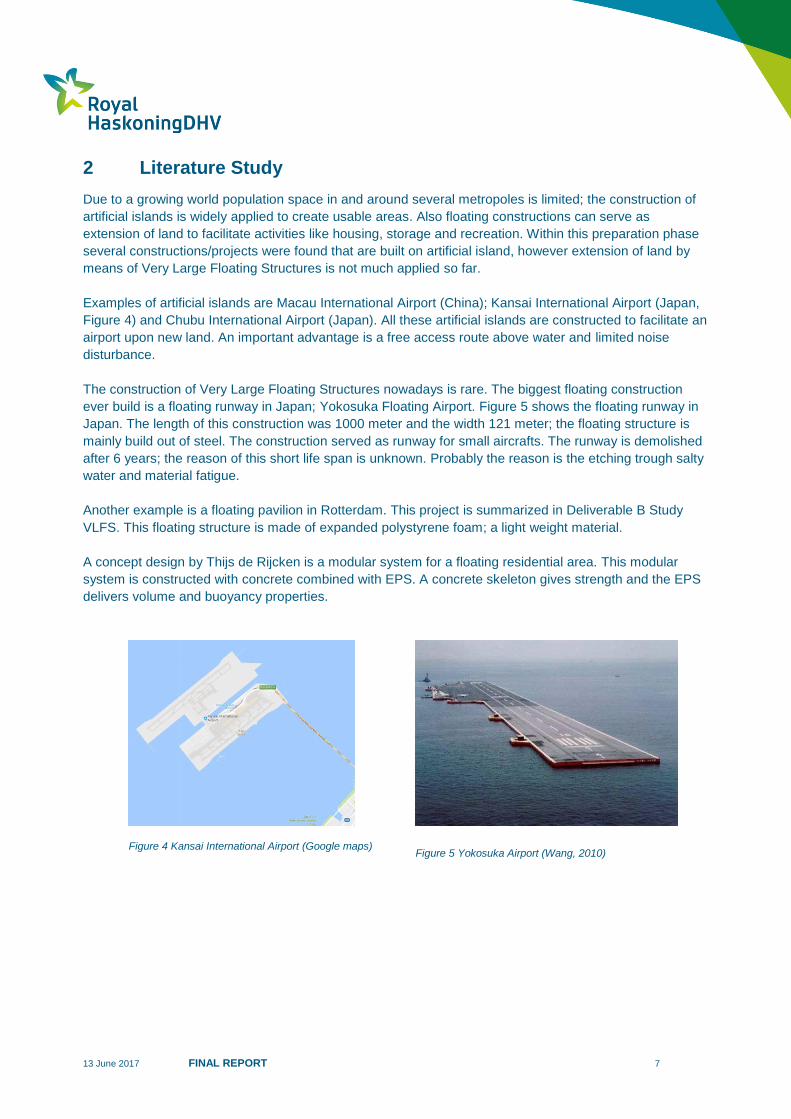
Examples of artificial islands are Macau International Airport (China); Kansai International Airport (Japan,
Figure 4) and Chubu International Airport (Japan). All these artificial islands are constructed to facilitate an
airport upon new land. An important advantage is a free access route above water and limited noise
disturbance.
The construction of Very Large Floating Structures nowadays is rare. The biggest floating construction
ever build is a floating runway in Japan; Yokosuka Floating Airport. Figure 5 shows the floating runway in
Japan. The length of this construction was 1000 meter and the width 121 meter; the floating structure is
mainly build out of steel. The construction served as runway for small aircrafts. The runway is demolished
after 6 years; the reason of this short life span is unknown. Probably the reason is the etching trough salty
water and material fatigue.
Another example is a floating pavilion in Rotterdam. This project is summarized in Deliverable B Study
VLFS. This floating structure is made of expanded polystyrene foam; a light weight material.
A concept design by Thijs de Rijcken is a modular system for a floating residential area. This modular
system is constructed with concrete combined with EPS. A concrete skeleton gives strength and the EPS
delivers volume and buoyancy properties.
Figure 5 Yokosuka Airport (Wang, 2010) Figure 4 Kansai International Airport (Google maps)
13 June 2017 FINAL REPORT 8
3 Statement of Requirements
Stakeholders 3.1
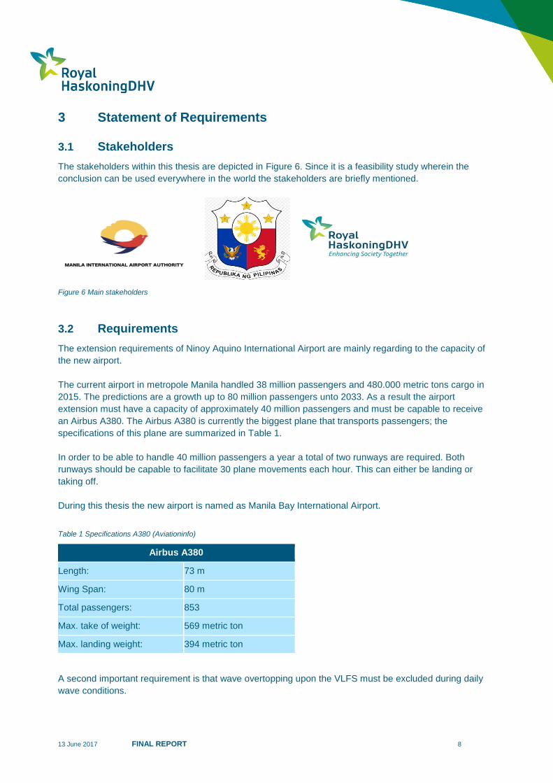
The stakeholders within this thesis are depicted in Figure 6. Since it is a feasibility study wherein the
conclusion can be used everywhere in the world the stakeholders are briefly mentioned.
Figure 6 Main stakeholders
Requirements 3.2
The extension requirements of Ninoy Aquino International Airport are mainly regarding to the capacity of
the new airport.
The current airport in metropole Manila handled 38 million passengers and 480.000 metric tons cargo in
2015. The predictions are a growth up to 80 million passengers unto 2033. As a result the airport
extension must have a capacity of approximately 40 million passengers and must be capable to receive
an Airbus A380. The Airbus A380 is currently the biggest plane that transports passengers; the
specifications of this plane are summarized in Table 1.
In order to be able to handle 40 million passengers a year a total of two runways are required. Both
runways should be capable to facilitate 30 plane movements each hour. This can either be landing or
taking off.
During this thesis the new airport is named as Manila Bay International Airport.
Table 1 Specifications A380 (Aviationinfo)
A second important requirement is that wave overtopping upon the VLFS must be excluded during daily
wave conditions.
Airbus A380
Length: 73 m
Wing Span: 80 m
Total passengers: 853
Max. take of weight: 569 metric ton
Max. landing weight: 394 metric ton

13 June 2017 FINAL REPORT 9
4 Local conditions
4.1 Introduction
This project is appointed to Manila Bay; there are plans to build three artificial island North-West of Cavite
City. The most norther island is planned as airport. For this location the local condition are collected and
summarized in Deliverable A; the Basis of Design.
Figure 7 depicts the schematized project location of the airport. Each side of the island shall experience
different hydraulic conditions; this result in differences in the design of a sea defence construction. The
final dimensions arise from the design phase and are elaborated later in this thesis.
The Basis of Design is mainly derived on the RHDHV reports of Pasay and Paranaque Reclamation
Development (RoyalHaskoningDHV, 2017) and Philippine Global Gateway (Stive, Confidential Report ,
2015). Some of the hydraulic conditions are determined in consultation with the supervisor of RHDHV
(Stive, 2017).
Figure 7 Project location Manila Bay International Airport

13 June 2017 FINAL REPORT 10
4.2 Environmental conditions
4.2.1 Chart datum
Chart datum is a reference level that is common to use in maritime engineering projects. Within this
project Mean Lowest Low Water (MLLW) is set as chart datum. Reason is the draft of vessels around the
construction. At Mean Lowest Low Water it is important that sailing around the land reclamation is
possible; the depth around the island and the VLFS have to be measured from Chart datum.
Chart Datum = Mean Lowest Low Water (MLLW)
Mean Lowest Low Water = 0.47 meter minus Mean Sea Level
Mean Sea Level = Chart Datum + 0.47 meter
Mean Lowest Low Water = Chart Datum + 0.0
4.2.2 Climate
Manila has a tropical monsoon climate. Tropical monsoon climates typifies to monthly mean temperatures
above 18°C every month of the year. Every year contains a wet and a dry season but also a winter and a
summer monsoon.
The west region of the Philippines is known for regularly passing typhoons. These typhoons cause high
wind speeds. Contrary to this the daily wind conditions are mild. Figure 8 shows that the wind during a
summer monsoon only reaches unto 10 m/sec out of the direction south west.
The typhoon conditions in Manila Bay are considered to be survival conditions and are summarized in
chapter 4.4.
Figure 8 Daily wind conditions over a year (Stive, Confidential Report , 2015)

13 June 2017 FINAL REPORT 11
4.2.3 Bathymetry
The bathymetry of Manila Bay has an effect on the hydraulic conditions around the land reclamation and
the floating structure. Likewise the depth of the seabed is one of the key points that lead to high cost of a
land reclamation project.
The depth of Manila Bay varies among 4 meter close to the shore up till 28 meters in the middle of the
bay. Figure 9 indicates the bathymetry at the location of Manila Bay International Airport. The bathymetry
over cross section A-A starts at a water depth of – 4 m and rises until - 18.5 m below Mean Sea Level
(MSL). Appendix A1 shows this bathymetry more detailed.
4.3 Geotechnical conditions
4.3.1 Soil profile
The seabed of Manila Bay consists out of different soil layers; the information about these layers is
obtained from a Standard Penetration Test. It has been adopted that the output of this test applies over
the total length of the island. Appendix A2 shows these layers over cross section A-A. It is called the
“typical cross section” and is regularly used during the design of the land reclamation.
The uppermost layers consist of soft silty clay and medium dense silty sand. The SPT gives N-values that
vary between the 0-10 blows. The underlying layers are very stiff clay and dense sand-hard clay with N
values unto 50 blows. These layers are considered suitable for foundation of the land reclamation.
4.3.2 Seismic activity
Manila is located in an earthquake prone area. Earthquakes in this area are caused by the sliding of the
plates from which the earth’s crust consists of. These plates are constantly moving and causing vibrations.
Earthquakes influence the land reclamation design enormously. In consultation with the supervisor of
RHDHV (Stive, 2017) is decided to disregard seismic activity in this thesis.
Figure 9 Bathymetry around Manila Bay International Airport

13 June 2017 FINAL REPORT 12
4.4 Hydraulic conditions
The most extreme hydraulic conditions at the project location occur throughout typhoons. By using outputs
of several models the conditions that occur around the project site are established. Within this feasibility
study the conditions are simplified in 3 load cases. Namely:
Daily conditions
Typhoon conditions
Post typhoon swell conditions
The hydraulic conditions that occur are waves with different length, heights and periods; currents, surges
and design water levels. Within this there is a distinction in different return periods; the most used return
period is 1 per 100 years. An overview of the hydraulic conditions is predicted in Table 2.
Table 2 Summary of Hydraulic conditions
Load cases
Sig
nif
ican
t w
ave h
eig
ht
Hs [
m]
Wav
e p
eri
od
T [
se
c]
Dir
ecti
on
[0
]
Desig
n W
ate
r L
ev
el
[m C
D]
Co
rre
sp
on
din
g t
ide le
vel
Su
rge h
eig
ht
[m]
Daily - operational
conditions 1 3-12 225 1.04 MHHW -
Survival - typhoon
conditions 7 9 270 1.92 - 0.8
Post typhoon
swell conditions 1.5 14 225 1.04 MHHW -
13 June 2017 FINAL REPORT 13
5 Traditional land reclamation
Footprint land reclamation 5.1
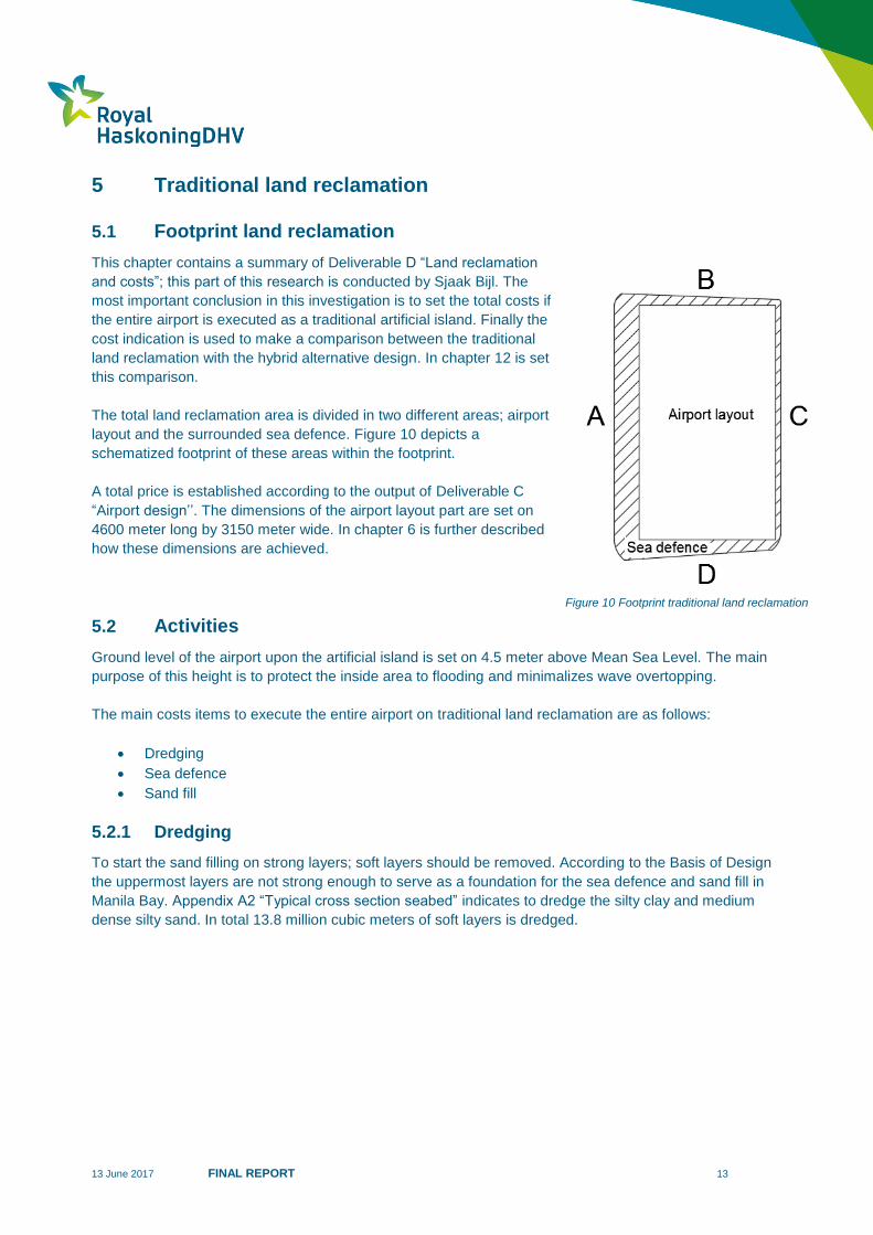
This chapter contains a summary of Deliverable D “Land reclamation
and costs”; this part of this research is conducted by Sjaak Bijl. The
most important conclusion in this investigation is to set the total costs if
the entire airport is executed as a traditional artificial island. Finally the
cost indication is used to make a comparison between the traditional
land reclamation with the hybrid alternative design. In chapter 12 is set
this comparison.
The total land reclamation area is divided in two different areas; airport
layout and the surrounded sea defence. Figure 10 depicts a
schematized footprint of these areas within the footprint.
A total price is established according to the output of Deliverable C
“Airport design’’. The dimensions of the airport layout part are set on
4600 meter long by 3150 meter wide. In chapter 6 is further described
how these dimensions are achieved.
Activities 5.2
Ground level of the airport upon the artificial island is set on 4.5 meter above Mean Sea Level. The main
purpose of this height is to protect the inside area to flooding and minimalizes wave overtopping.
The main costs items to execute the entire airport on traditional land reclamation are as follows:
Dredging
Sea defence
Sand fill
5.2.1 Dredging
To start the sand filling on strong layers; soft layers should be removed. According to the Basis of Design
the uppermost layers are not strong enough to serve as a foundation for the sea defence and sand fill in
Manila Bay. Appendix A2 “Typical cross section seabed” indicates to dredge the silty clay and medium
dense silty sand. In total 13.8 million cubic meters of soft layers is dredged.
Figure 10 Footprint traditional land reclamation
13 June 2017 FINAL REPORT 14
5.2.2 Sea defence
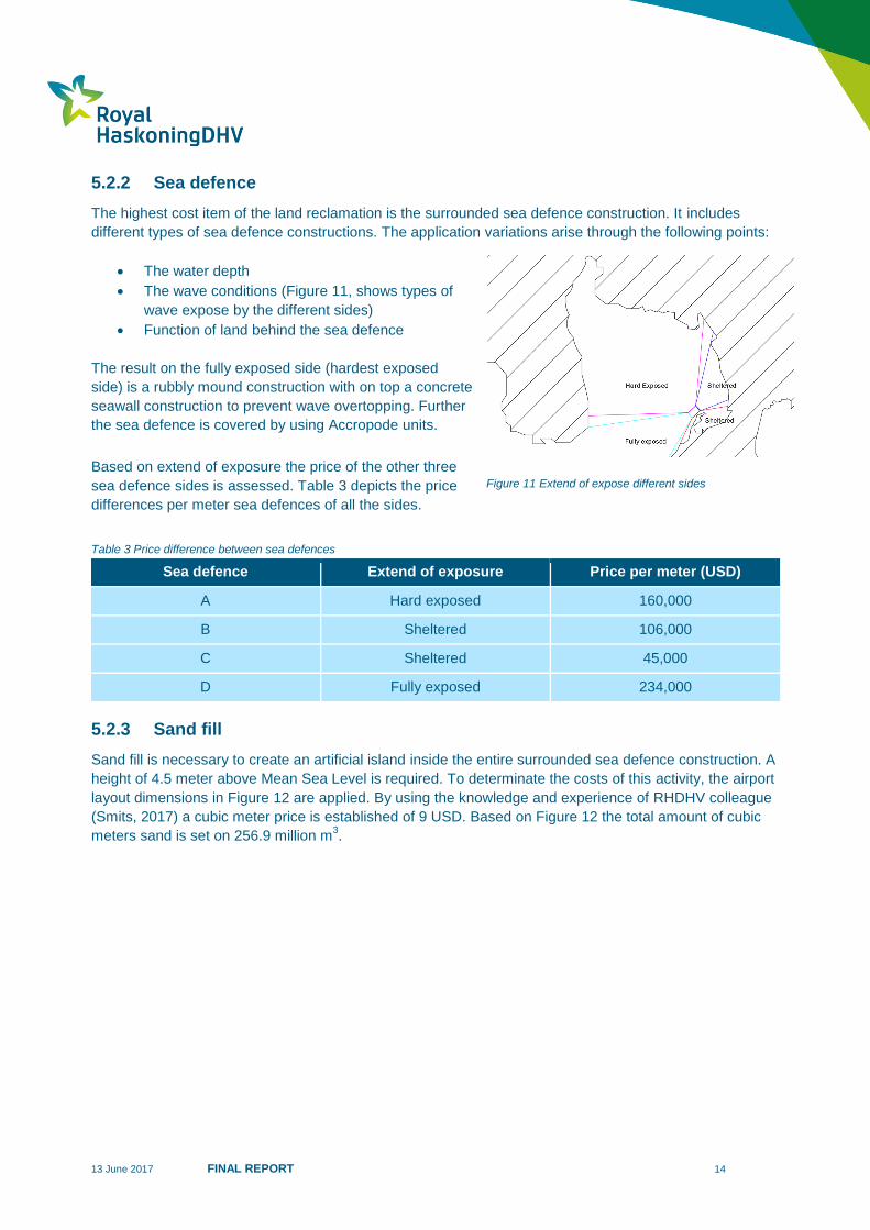
The highest cost item of the land reclamation is the surrounded sea defence construction. It includes
different types of sea defence constructions. The application variations arise through the following points:
The water depth
The wave conditions (Figure 11, shows types of
wave expose by the different sides)
Function of land behind the sea defence
The result on the fully exposed side (hardest exposed
side) is a rubbly mound construction with on top a concrete
seawall construction to prevent wave overtopping. Further
the sea defence is covered by using Accropode units.
Based on extend of exposure the price of the other three
sea defence sides is assessed. Table 3 depicts the price
differences per meter sea defences of all the sides.
Table 3 Price difference between sea defences
Sea defence Extend of exposure Price per meter (USD)
A Hard exposed 160,000
B Sheltered 106,000
C Sheltered 45,000
D Fully exposed 234,000
5.2.3 Sand fill
Sand fill is necessary to create an artificial island inside the entire surrounded sea defence construction. A
height of 4.5 meter above Mean Sea Level is required. To determinate the costs of this activity, the airport
layout dimensions in Figure 12 are applied. By using the knowledge and experience of RHDHV colleague
(Smits, 2017) a cubic meter price is established of 9 USD. Based on Figure 12 the total amount of cubic
meters sand is set on 256.9 million m3.
Figure 11 Extend of expose different sides
13 June 2017 FINAL REPORT 15
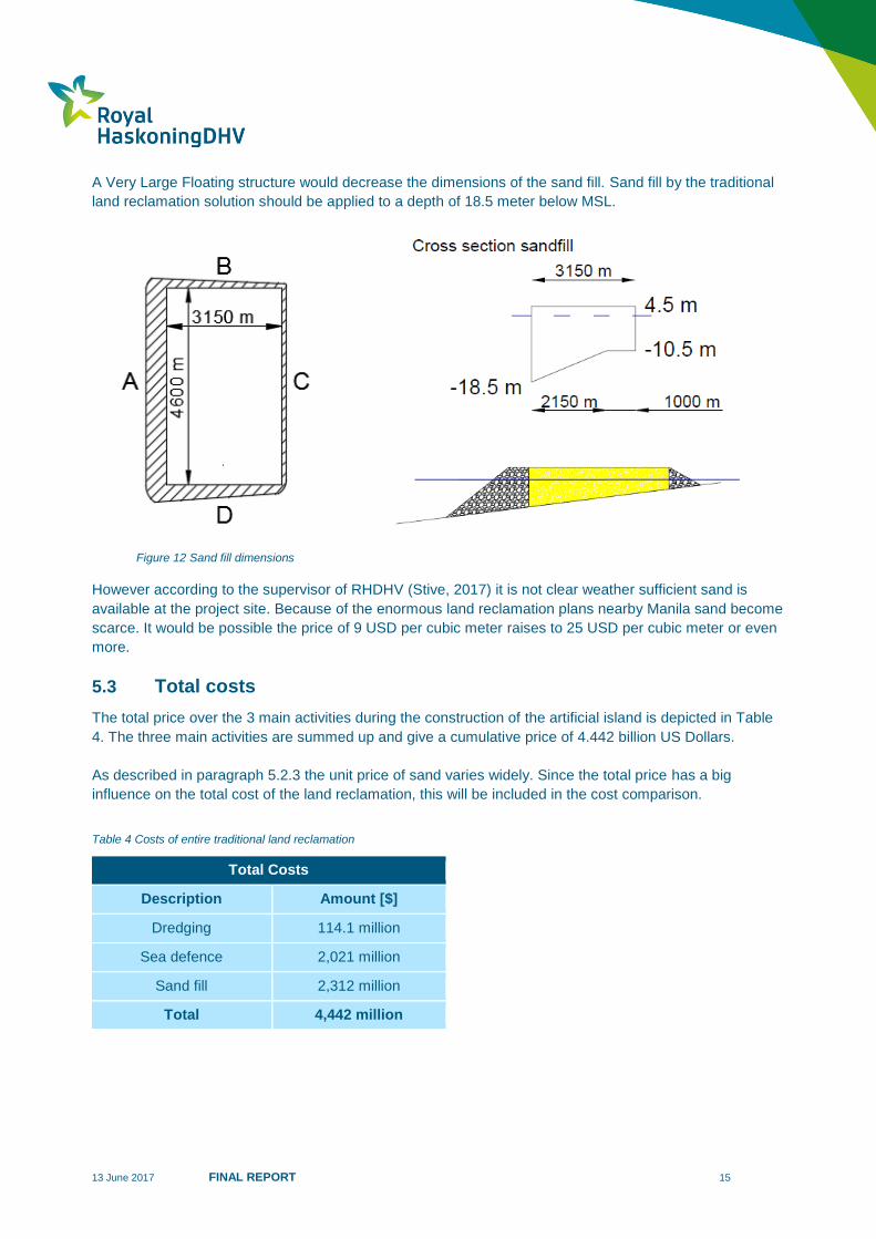
A Very Large Floating structure would decrease the dimensions of the sand fill. Sand fill by the traditional
land reclamation solution should be applied to a depth of 18.5 meter below MSL.
However according to the supervisor of RHDHV (Stive, 2017) it is not clear weather sufficient sand is
available at the project site. Because of the enormous land reclamation plans nearby Manila sand become
scarce. It would be possible the price of 9 USD per cubic meter raises to 25 USD per cubic meter or even
more.
Total costs 5.3
The total price over the 3 main activities during the construction of the artificial island is depicted in Table
4. The three main activities are summed up and give a cumulative price of 4.442 billion US Dollars.
As described in paragraph 5.2.3 the unit price of sand varies widely. Since the total price has a big
influence on the total cost of the land reclamation, this will be included in the cost comparison.
Table 4 Costs of entire traditional land reclamation
Total Costs
Description Amount [$]
Dredging 114.1 million
Sea defence 2,021 million
Sand fill 2,312 million
Total 4,442 million
Figure 12 Sand fill dimensions
13 June 2017 FINAL REPORT 16
6 Airport design
Floating facilities 6.1
To understand if a Very Large Floating structure can be implemented in the future airport, a study to the
airport and runway facilities of Manila Bay International Airport is required. This investigation results in a
reference design of Manila Bay International Airport, where all required facilities included. During this
research there has been contact with the company NACO Airport Consultancy and Engineering, which is
a company of Royal Haskoning DHV.
Earlier mentioned Manila Bay International Airport serves a capacity of 40 million passengers a year
wherein a dual runway is applied. Based on the predominant wind direction of southeast, it results both
runways are located to WSW (west southwest) and ENE (east northeast). On basis of a RHDHV study
about Manila Bay International Airport (HNM / FBK, 2014), the main parts of the airport layout are:
Northern runway
Other facilities (terminal, apron, hangar, cargo, taxiways)
Southern runway
Table 5 Determination floating facilities
Facility Main variable average load (N/m2)
Safely executed as
floating
Terminal Unknown No
Apron 322 ?
Northern runway (only landing) 2.2 Yes
Southern runway (only take-off) 3.2 Yes
Taxiway 3.2 Yes
Hangar >207 ?
Cargo 207-322 ?
To understand which facility has the possibility to be
executed as floating, is established which main variable
average loads are presented at each facility. Normative
loads at this airport are the airplanes (Airbus A380) or
smaller. This results in Table 5, where is concluded that
both runways and taxiways have the possibility to be safely
executed as floating structure as the variable loads will
cause minimum impact on the buoyancy.
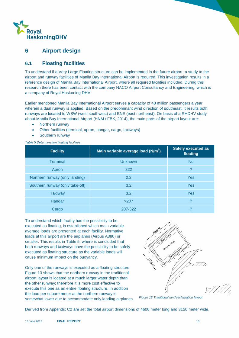
Only one of the runways is executed as a floating structure.
Figure 13 shows that the northern runway in the traditional
airport layout is located at a much larger water depth than
the other runway; therefore it is more cost effective to
execute this one as an entire floating structure. In addition
the load per square meter at the northern runway is
somewhat lower due to accommodate only landing airplanes.
Derived from Appendix C2 are set the total airport dimensions of 4600 meter long and 3150 meter wide.
Figure 13 Traditional land reclamation layout
13 June 2017 FINAL REPORT 17
Other facilities 6.2
All the other facilities of Manila Bay International airport have executed as an artificial island. Buildings
(terminal, hangar and cargo terminal) and aprons are positioned logically using the guideline for designing
an airport (International Civil Aviation Organization, 2013). Thereby in this hybrid alternative design the
southern runway is also located on the artificial island. Appendix C2 indicates how both the hybrid
alternative design as the traditional land reclamation is classified.
Floating northern runway 6.3
6.3.1 Build-up
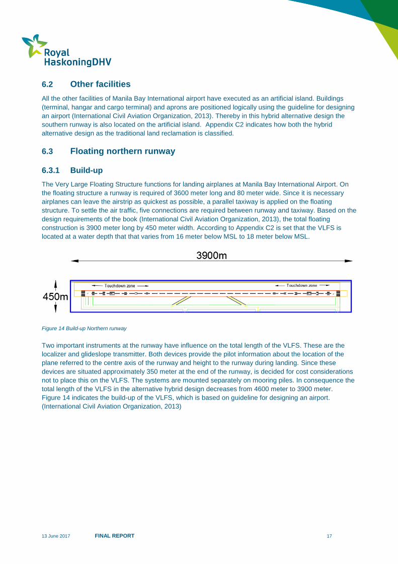
The Very Large Floating Structure functions for landing airplanes at Manila Bay International Airport. On
the floating structure a runway is required of 3600 meter long and 80 meter wide. Since it is necessary
airplanes can leave the airstrip as quickest as possible, a parallel taxiway is applied on the floating
structure. To settle the air traffic, five connections are required between runway and taxiway. Based on the
design requirements of the book (International Civil Aviation Organization, 2013), the total floating
construction is 3900 meter long by 450 meter width. According to Appendix C2 is set that the VLFS is
located at a water depth that that varies from 16 meter below MSL to 18 meter below MSL.
Figure 14 Build-up Northern runway
Two important instruments at the runway have influence on the total length of the VLFS. These are the
localizer and glideslope transmitter. Both devices provide the pilot information about the location of the
plane referred to the centre axis of the runway and height to the runway during landing. Since these
devices are situated approximately 350 meter at the end of the runway, is decided for cost considerations
not to place this on the VLFS. The systems are mounted separately on mooring piles. In consequence the
total length of the VLFS in the alternative hybrid design decreases from 4600 meter to 3900 meter.
Figure 14 indicates the build-up of the VLFS, which is based on guideline for designing an airport.
(International Civil Aviation Organization, 2013)

13 June 2017 FINAL REPORT 18
6.3.2 Connection artificial island
The floating runway construction must be connected to the artificial island. A bridge connection which
functions as taxiway is therefore necessary for airplanes to reach the vertically “fixed’’ part of the
aerodrome. Based on the maximal longitudinal slope at the taxiway, a length of 250 meter is required. It is
essential to minimize the connections because the costs are high and the construction is very
complicated.
Three connections are applied between the floating and fixed part of the airport. In consultation with senior
airport development advisor of NACO (Baijer, 2017) three connections can generally settled the air traffic.
In Appendix C3 is depicted the bridge connection in the normative situation between the floating structure
to the fixed airport. The level of the floating structure is based on the LAT (lowest astronomical tide, -
1.04m MSL) with a freeboard of 2.0 meter. This value is set in consultation with the supervisor of RHDHV.
(Stive, 2017)
First it consists of a part of 236 meter, which moves on the floating structure by the water level and on the
other side is mounted on a concrete pole. The last 14 meter is a safety distance which leads to the fixed
airport. On the fixed airport the connection connects at a height of MSL +4.50 meter. Important to mention
is that this connection is not elaborated further in this thesis.
Figure 15 shows the taxiway connection between the VLFS and the vertically fixed airport.
Figure 15 Taxiway connection
13 June 2017 FINAL REPORT 19
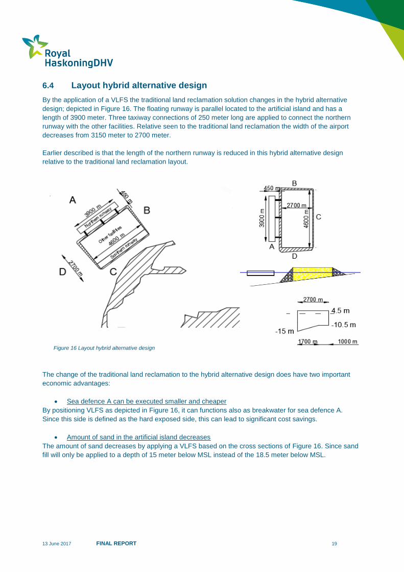
Layout hybrid alternative design 6.4
By the application of a VLFS the traditional land reclamation solution changes in the hybrid alternative
design; depicted in Figure 16. The floating runway is parallel located to the artificial island and has a
length of 3900 meter. Three taxiway connections of 250 meter long are applied to connect the northern
runway with the other facilities. Relative seen to the traditional land reclamation the width of the airport
decreases from 3150 meter to 2700 meter.
Earlier described is that the length of the northern runway is reduced in this hybrid alternative design
relative to the traditional land reclamation layout.
The change of the traditional land reclamation to the hybrid alternative design does have two important
economic advantages:
Sea defence A can be executed smaller and cheaper
By positioning VLFS as depicted in Figure 16, it can functions also as breakwater for sea defence A.
Since this side is defined as the hard exposed side, this can lead to significant cost savings.
Amount of sand in the artificial island decreases
The amount of sand decreases by applying a VLFS based on the cross sections of Figure 16. Since sand
fill will only be applied to a depth of 15 meter below MSL instead of the 18.5 meter below MSL.
Figure 16 Layout hybrid alternative design
13 June 2017 FINAL REPORT 20
7 Structural Analysis
Elastic deformable construction 7.1
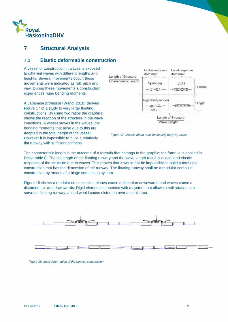
A vessel or construction in waves is exposed
to different waves with different lengths and
heights. Several movements occur; these
movements were indicated as roll, pitch and
yaw. During these movements a construction
experiences huge bending moments.
A Japanese professor (Wang, 2010) derived
Figure 17 of a study to very large floating
constructions. By using two ratios the graphics
shows the reaction of the structure in the wave
conditions. A vessel moves in the waves; the
bending moments that arise due to this are
adopted in the total height of the vessel.
However it is impossible to build a relatively
flat runway with sufficient stiffness.
The characteristic length is the outcome of a formula that belongs to the graphic; the formula is applied in
Deliverable E. The big length of the floating runway and the wave length result is a local and elastic
response of the structure due to waves. This proves that it would not be impossible to build a total rigid
construction that has the dimension of the runway. The floating runway shall be a modular compiled
construction by means of a hinge connection system
Figure 18 shows a modular cross section, planes cause a distortion downwards and waves cause a
distortion up- and downwards. Rigid elements connected with a system that allows small rotation can
serve as floating runway; a load would cause distortion over a small area.
Figure 17 Graphic about reaction floating body by waves
Figure 18 Local deformation of the runway construction
13 June 2017 FINAL REPORT 21
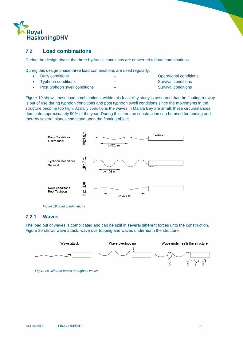
Load combinations 7.2
During the design phase the three hydraulic conditions are converted to load combinations.
During this design phase three load combinations are used regularly:
Daily conditions – Operational conditions
Typhoon conditions – Survival conditions
Post typhoon swell conditions – Survival conditions
Figure 19 shows these load combinations, within this feasibility study is assumed that the floating runway
is out of use during typhoon conditions and post typhoon swell conditions since the movements in the
structure become too high. At daily conditions the waves in Manila Bay are small; these circumstances
dominate approximately 90% of the year. During this time the construction can be used for landing and
thereby several planes can stand upon the floating object.
7.2.1 Waves
The load out of waves is complicated and can be split in several different forces unto the construction.
Figure 20 shows wave attack, wave overtopping and waves underneath the structure.
Figure 19 Load combinations
Figure 20 Different forces throughout waves
13 June 2017 FINAL REPORT 22
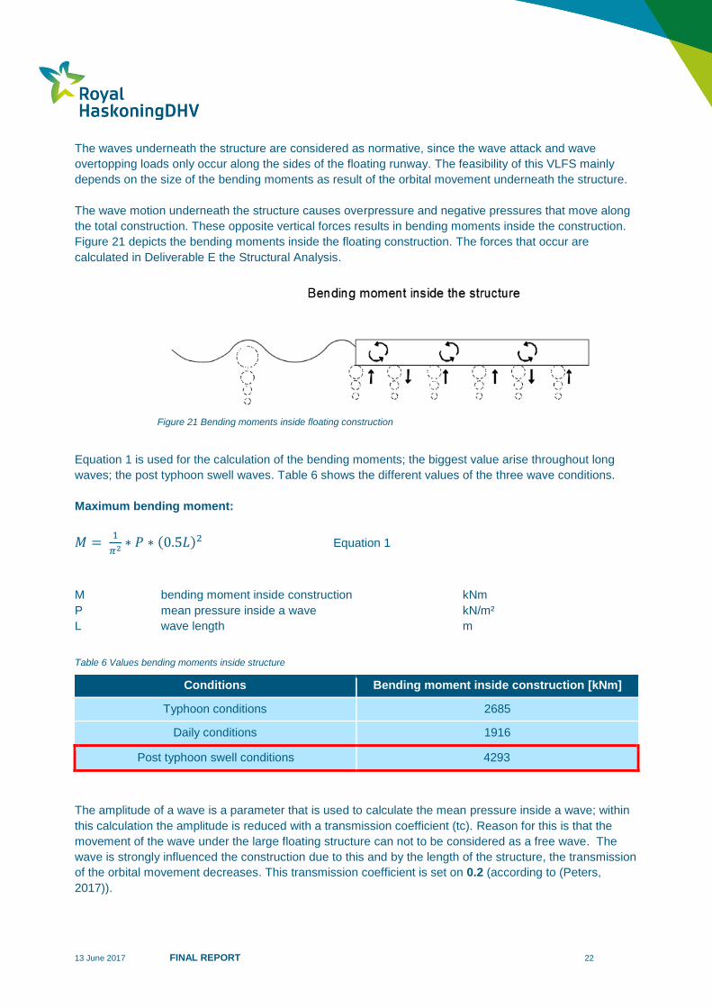
The waves underneath the structure are considered as normative, since the wave attack and wave
overtopping loads only occur along the sides of the floating runway. The feasibility of this VLFS mainly
depends on the size of the bending moments as result of the orbital movement underneath the structure.
The wave motion underneath the structure causes overpressure and negative pressures that move along
the total construction. These opposite vertical forces results in bending moments inside the construction.
Figure 21 depicts the bending moments inside the floating construction. The forces that occur are
calculated in Deliverable E the Structural Analysis.
Equation 1 is used for the calculation of the bending moments; the biggest value arise throughout long
waves; the post typhoon swell waves. Table 6 shows the different values of the three wave conditions.
Maximum bending moment:
𝑀 = 1
𝜋2 ∗ 𝑃 ∗ (0.5𝐿)2 Equation 1
M bending moment inside construction kNm
P mean pressure inside a wave kN/m²
L wave length m
Table 6 Values bending moments inside structure
The amplitude of a wave is a parameter that is used to calculate the mean pressure inside a wave; within
this calculation the amplitude is reduced with a transmission coefficient (tc). Reason for this is that the
movement of the wave under the large floating structure can not to be considered as a free wave. The
wave is strongly influenced the construction due to this and by the length of the structure, the transmission
of the orbital movement decreases. This transmission coefficient is set on 0.2 (according to (Peters,
2017)).
Conditions Bending moment inside construction [kNm]
Typhoon conditions 2685
Daily conditions 1916
Post typhoon swell conditions 4293
Figure 21 Bending moments inside floating construction
13 June 2017 FINAL REPORT 23
7.2.2 Airplane
To ensure an airplane can be adopted in a rigid floating element, the runway should be modularly
constructed. A plane causes a displacement of water over a certain area and thereby a deeper draft. The
water underneath the construction gives resistance to the downward movement. An airplane upon the
floating structure can be compared with a person on a trampoline.
A rigid segment can be obtained by designing the element sufficient high. The desired result is that
deflection of the segment is minimized. An airplane causes bending moments in the segments and shear
forces in the connection system. Concluded of Deliverable E “Structural Analyses’’ is set that the bending
moment throughout an Airbus A380 is smaller than the bending moment that arises throughout the post
typhoon swell waves.
Based on Table 6 is concluded the normative load that arises in the elements is 4293kNm.
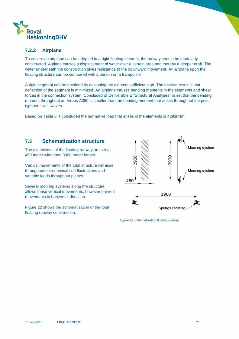
Schematization structure 7.3
The dimensions of the floating runway are set at
450 meter width and 3900 meter length.
Vertical movements of the total structure will arise
throughout astronomical tide fluctuations and
variable loads throughout planes.
Several mooring systems along the structure
allows these vertical movements, however prevent
movements in horizontal direction.
Figure 22 shows the schematization of the total
floating runway construction.
Figure 22 Schematization floating runway
13 June 2017 FINAL REPORT 24
8 Design floating segments
Cross section shape 8.1
This chapter contains a summary of Deliverable F “Concept design floating segment”; this part of this
research is conducted by Sjaak Bijl. The design of the floating runway consists of several building
segments. Subsequently different shapes of building blocks in the cross section are possible. A cross
section shape has to provide a surface to attach the connection system between the segments.
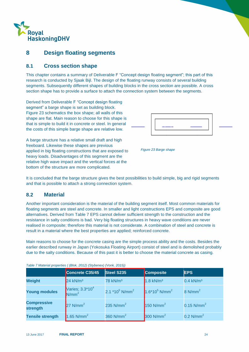
Derived from Deliverable F “Concept design floating
segment” a barge shape is set as building block.
Figure 23 schematics the box shape; all walls of this
shape are flat. Main reason to choose for this shape is
that is simple to build it in concrete or steel. In general
the costs of this simple barge shape are relative low.
A barge structure has a relative small draft and high
freeboard. Likewise these shapes are previous
applied in big floating constructions that are exposed to
heavy loads. Disadvantages of this segment are the
relative high wave impact and the vertical forces at the
bottom of the structure are more complicated.
It is concluded that the barge structure gives the best possibilities to build simple, big and rigid segments
and that is possible to attach a strong connection system.
Material 8.2
Another important consideration is the material of the building segment itself. Most common materials for
floating segments are steel and concrete. In smaller and light constructions EPS and composite are good
alternatives. Derived from Table 7 EPS cannot deliver sufficient strength to the construction and the
resistance in salty conditions is bad. Very big floating structures in heavy wave conditions are never
realised in composite; therefore this material is not considerate. A combination of steel and concrete is
result in a material where the best properties are applied; reinforced concrete.
Main reasons to choose for the concrete casing are the simple process ability and the costs. Besides the
earlier described runway in Japan (Yokosuka Floating Airport) consist of steel and is demolished probably
due to the salty conditions. Because of this past it is better to choose the material concrete as casing.
Table 7 Material properties ( (Blok, 2012) (Stybenex) (Vonk, 2015))
Concrete C35/45 Steel S235 Composite EPS
Weight 24 kN/m³ 78 kN/m³ 1.8 kN/m³ 0.4 kN/m³
Young modules Varies; 3.3*10
4
N/mm2
2.1 *105 N/mm
2 1.6*10
5 N/mm
2 8 N/mm
2
Compressive
strength 27 N/mm
2 235 N/mm
2 150 N/mm
2 0.15 N/mm
2
Tensile strength 1.65 N/mm2 360 N/mm
2 300 N/mm
2 0.2 N/mm
2
Figure 23 Barge shape

13 June 2017 FINAL REPORT 25
9 Grid structure
Placement segments 9.1
Before determining the size of the segment and type of connections, it is essential to understand how the
grid structure of all the floating elements is formed. A grid structure gives in the top view the pattern
wherein all the segments are placed to ultimately form the entire runway construction. The shape of the
segment in top view is earlier set as a box shape. However seen in the top view different patterns are also
possible. Due to the waves in Manila Bay all the segments must be laid in an optimized grid structure.
Explanation principle grid 9.2
When a wave field reaches a specific grid structure, it is required that forces and bending moments can be
absorbed by the segments. Most important principle is that segments should be able to absorb as many
waves as possible from different directions. When a wave reaches a separate segment, it rolls underneath
the structure; this is depicted in Figure 24. A bending moment arises inside the floating segment which
must be absorbed by the element itself.
Figure 24 Occurring bending moment by waves (one segment)
If a situation with two connected segments is considered, see Figure 25, a wave rolls also underneath the
elements and causes bending moments inside both structures. Earlier mentioned is that a hinge
connection system is applied and allows rotations. When a wave rolls underneath both connected
segments, a rotation arises between the floating structures. This rotation is caused by overpressure and
negative pressures of waves that move along the total construction. If the wave length is longer, the
rotation between the floating structures will increase.
Figure 25 Occurring bending moment by waves (two connected segments)
The purpose is to set a favourable grid structure which divide the rotations between elements as best as
possible across all the elements and distributing the forces as well as possible. Consequence is that a grid
structure is required that has high strength properties in all directions.
13 June 2017 FINAL REPORT 26
Requisite pattern 9.3
9.3.1 Grid structure
To understand when a grid structure has high strength properties against the presented waves is set a
comparison between the half-stone pattern and herringbone structure. Both structures are implemented
as the floating runway construction in Manila Bay.
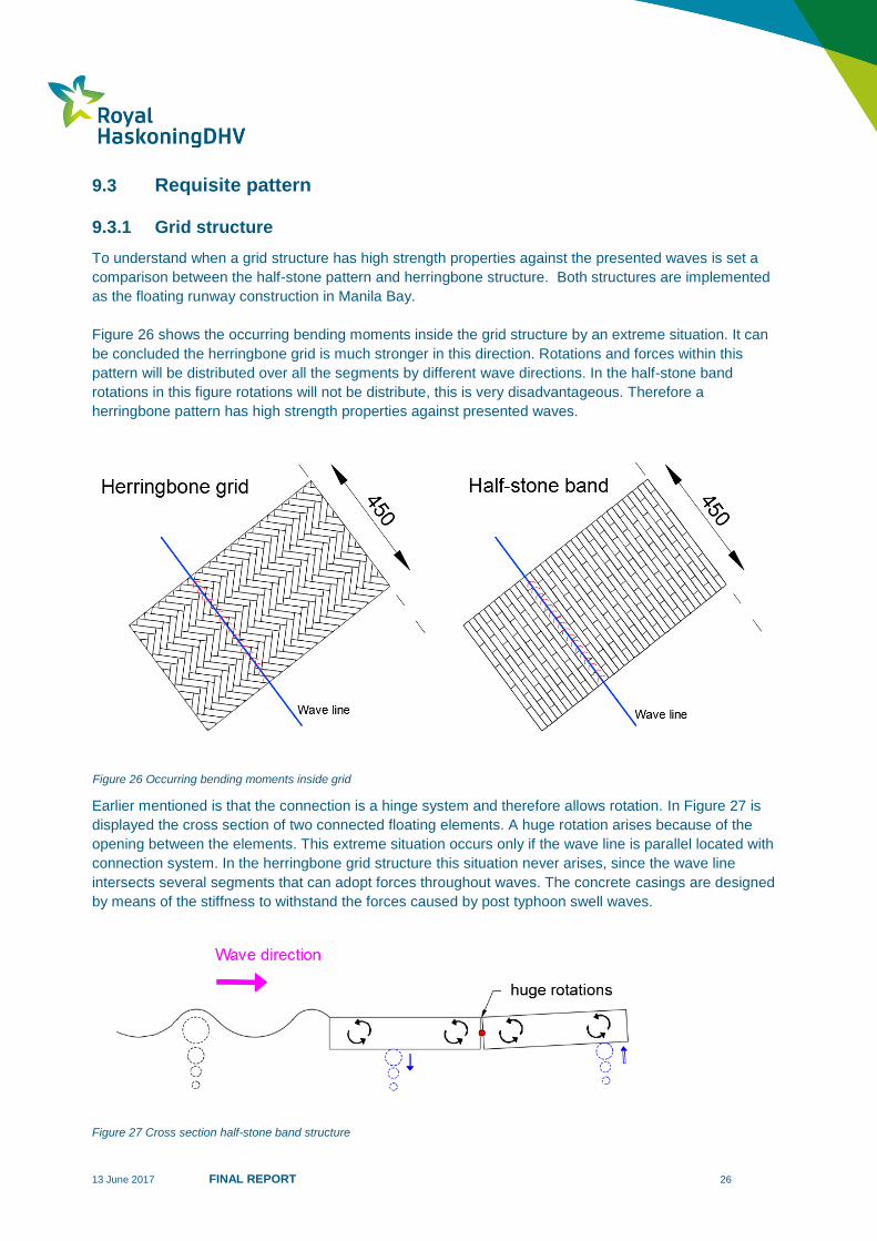
Figure 26 shows the occurring bending moments inside the grid structure by an extreme situation. It can
be concluded the herringbone grid is much stronger in this direction. Rotations and forces within this
pattern will be distributed over all the segments by different wave directions. In the half-stone band
rotations in this figure rotations will not be distribute, this is very disadvantageous. Therefore a
herringbone pattern has high strength properties against presented waves.
Earlier mentioned is that the connection is a hinge system and therefore allows rotation. In Figure 27 is
displayed the cross section of two connected floating elements. A huge rotation arises because of the
opening between the elements. This extreme situation occurs only if the wave line is parallel located with
connection system. In the herringbone grid structure this situation never arises, since the wave line
intersects several segments that can adopt forces throughout waves. The concrete casings are designed
by means of the stiffness to withstand the forces caused by post typhoon swell waves.
Figure 27 Cross section half-stone band structure
Figure 26 Occurring bending moments inside grid
13 June 2017 FINAL REPORT 27
9.3.2 Connections
Several different grid structures are assessed and rated with a percentage. Thereby within a certain grid
different width-length ratios are possible. Different sizes of ratios are investigated; these are 1:2, 1:3 and
1:4. Higher ratios are disregarded, since these are detrimental to the workability and strength of the
elements.
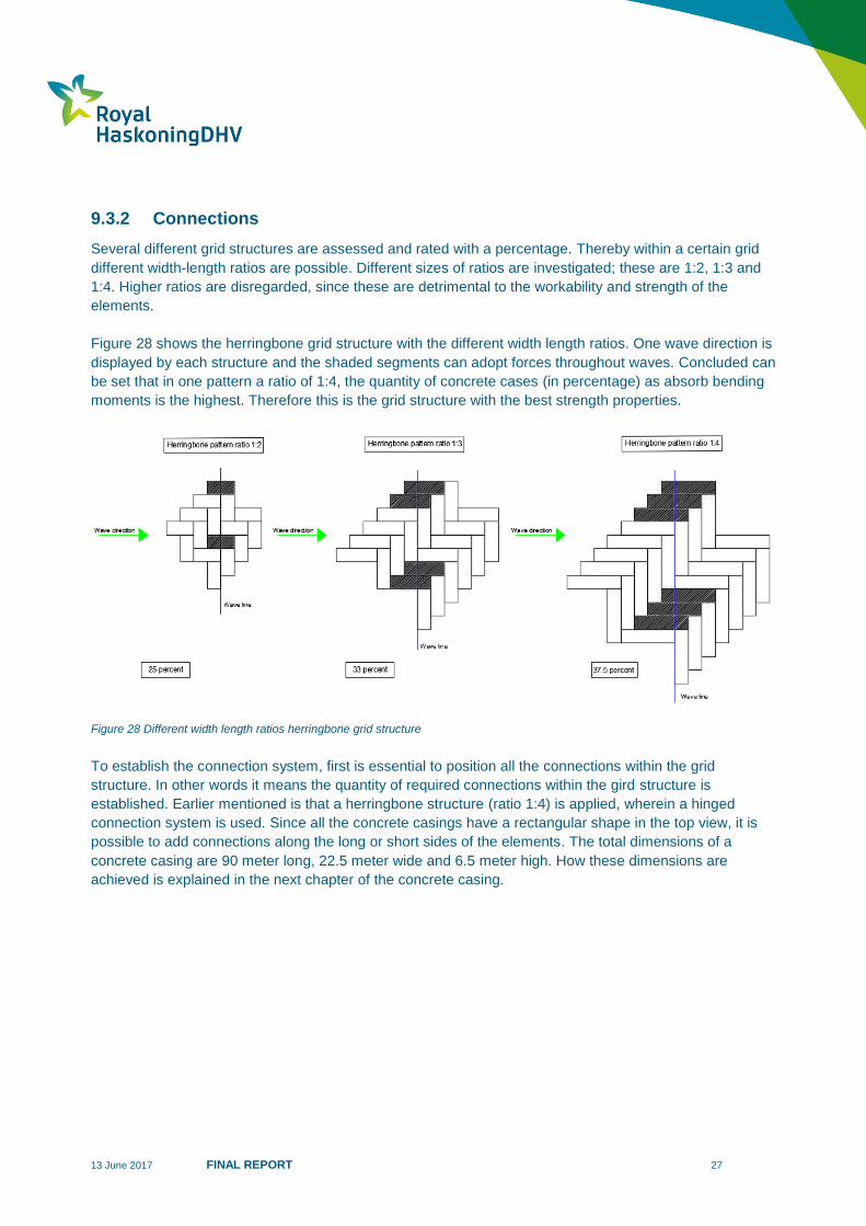
Figure 28 shows the herringbone grid structure with the different width length ratios. One wave direction is
displayed by each structure and the shaded segments can adopt forces throughout waves. Concluded can
be set that in one pattern a ratio of 1:4, the quantity of concrete cases (in percentage) as absorb bending
moments is the highest. Therefore this is the grid structure with the best strength properties.
Figure 28 Different width length ratios herringbone grid structure
To establish the connection system, first is essential to position all the connections within the grid
structure. In other words it means the quantity of required connections within the gird structure is
established. Earlier mentioned is that a herringbone structure (ratio 1:4) is applied, wherein a hinged
connection system is used. Since all the concrete casings have a rectangular shape in the top view, it is
possible to add connections along the long or short sides of the elements. The total dimensions of a
concrete casing are 90 meter long, 22.5 meter wide and 6.5 meter high. How these dimensions are
achieved is explained in the next chapter of the concrete casing.
13 June 2017 FINAL REPORT 28
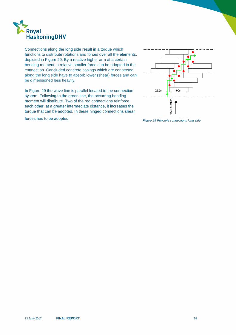
Connections along the long side result in a torque which
functions to distribute rotations and forces over all the elements,
depicted in Figure 29. By a relative higher arm at a certain
bending moment, a relative smaller force can be adopted in the
connection. Concluded concrete casings which are connected
along the long side have to absorb lower (shear) forces and can
be dimensioned less heavily.
In Figure 29 the wave line is parallel located to the connection
system. Following to the green line, the occurring bending
moment will distribute. Two of the red connections reinforce
each other; at a greater intermediate distance, it increases the
torque that can be adopted. In these hinged connections shear
forces has to be adopted.
Figure 29 Principle connections long side
13 June 2017 FINAL REPORT 29
Chosen herringbone structure 9.4
Different grid structures are drawn up in a longlist. In this stocktaking different patterns and shapes are
used. Main goal is to set a grid structure which can divide the rotations between the segments and
distributing the forces as well. However in view of the project goal, it is also required to minimize the costs.
It means manufacturability and experience in the execution are important requirements for the grid
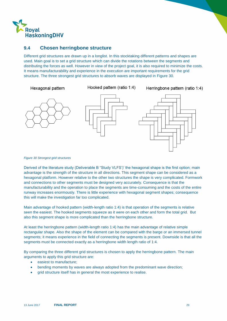
structure. The three strongest grid structures to absorb waves are displayed in Figure 30.
Figure 30 Strongest grid structures
Derived of the literature study (Deliverable B “Study VLFS’)’ the hexagonal shape is the first option; main
advantage is the strength of the structure in all directions. This segment shape can be considered as a
hexagonal platform. However relative to the other two structures the shape is very complicated. Formwork
and connections to other segments must be designed very accurately. Consequence is that the
manufacturability and the operation to place the segments are time-consuming and the costs of the entire
runway increases enormously. There is little experience with hexagonal segment shapes; consequence
this will make the investigation far too complicated.
Main advantage of hooked pattern (width-length ratio 1:4) is that operation of the segments is relative
seen the easiest. The hooked segments squeeze as it were on each other and form the total grid. But
also this segment shape is more complicated than the herringbone structure.
At least the herringbone pattern (width-length ratio 1:4) has the main advantage of relative simple
rectangular shape. Also the shape of the element can be compared with the barge or an immersed tunnel
segments; it means experience in the field of connecting the segments is present. Downside is that all the
segments must be connected exactly as a herringbone width length ratio of 1:4.
By comparing the three different grid structures is chosen to apply the herringbone pattern. The main
arguments to apply this grid structure are:
easiest to manufacture;
bending moments by waves are always adopted from the predominant wave direction;
grid structure itself has in general the most experience to realise.
13 June 2017 FINAL REPORT 30
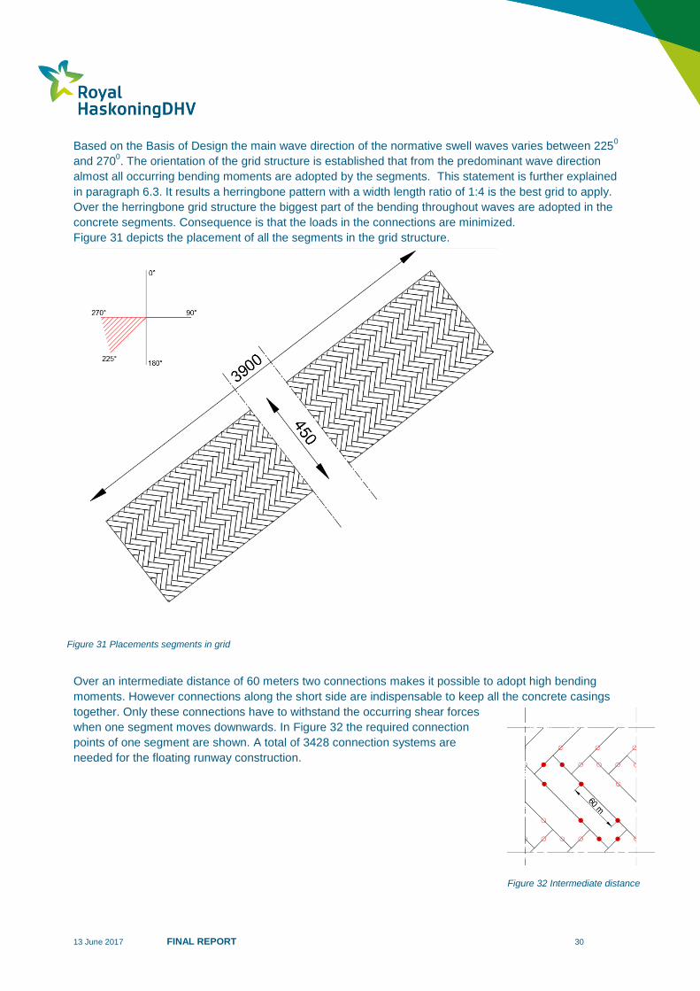
Based on the Basis of Design the main wave direction of the normative swell waves varies between 2250
and 2700. The orientation of the grid structure is established that from the predominant wave direction
almost all occurring bending moments are adopted by the segments. This statement is further explained
in paragraph 6.3. It results a herringbone pattern with a width length ratio of 1:4 is the best grid to apply.
Over the herringbone grid structure the biggest part of the bending throughout waves are adopted in the
concrete segments. Consequence is that the loads in the connections are minimized.
Figure 31 depicts the placement of all the segments in the grid structure.
Over an intermediate distance of 60 meters two connections makes it possible to adopt high bending
moments. However connections along the short side are indispensable to keep all the concrete casings
together. Only these connections have to withstand the occurring shear forces
when one segment moves downwards. In Figure 32 the required connection
points of one segment are shown. A total of 3428 connection systems are
needed for the floating runway construction.
Figure 31 Placements segments in grid
Figure 32 Intermediate distance
13 June 2017 FINAL REPORT 31
10 Connection system
Longlist 10.1
10.1.1 Boundary conditions
Within this feasibility study the hinge connection system is one of the most critical points. This system has
to withstand the normative shear forces of an Airbus A380 and post typhoon swell waves. Besides it
means the hinge system has to rotate in upwards (airplane + waves) and in the downwards (waves)
direction. Reason is to ensure the floating runway construction response elastically and deformed local.
Another important boundary condition is that the maximum required distance between the elements is
determined. Since it should never occur that an airplane can come with their wheels in the seam between
the floating elements. Consequence is that the presented airplane with the smallest wheels at Manila Bay
International Airport is determined. It requires that the maximum intermediate distance between the
segments is not higher than 20 centimetres.
10.1.2 Alternatives
An alternative system is to put a steel cable throughout the segments and tensioning the cables. It creates
a strong connection and limited rotation is possible. However it is really hard to realise this for all the
connections over the total runway construction. Next a hinge combined with a spring is an alternative
where two connection elements work together. The hinge allows rotation and the spring can be pressed or
depressed. Downside is that there is hardly any experience to apply this system.
A connected fender system with bolts is also a serious option. Fenders consist mainly of rubber, which is a
very elastic material. This material is also good resistant against salt water. Another alternative is to
customize both ends of the segments, In this case, segments fall into each other like puzzles, whereby
also a thin layer of rubber or synthetic material is applied. As last a pin connection is potential solution,
whereby one segment has a sort of steel pin, which can interlocked with the other floating element. Main
advantage is the easy execution; however a downside is that corrosion problems can occur. In Appendix
H1 all the connection systems are schematically depicted
10.1.3 Chosen final system
A longlist is set for all the alternative connection systems. To determine the final system selection criteria
are used to rate the alternatives. One of the most important requirements in relation to the project goal is
that it is technically possible to apply the system for in total 3428 connections. It means the connection
should be easy to manufactural and to execute. But the system must be able to function in the heavy
wave conditions of Manila Bay and withstand the impact of an airplane.
Another important requirement is that the costs should be limited. It means a simple, sufficient strong
connection is attractive. Therefore the connection should be consisting of limited, easy obtainable
components.
Other less important criteria are durability and maintainability. The lifespan of the connection system
should be certainly decades. Components inside a connection which are constantly exposed to the sea
water are salt-resistant materials. Maintenance should also be considered; therefore the connected
segments should have the possibility to disconnect. It must be possible to unlock a segment in the final
grid structure for maintenance or even replacement.
13 June 2017 FINAL REPORT 32
By comparing the all the alternative connection systems, the hinge combined with a spring and the fender
solution are the most feasible. The main arguments to apply a hinge combined with a spring are:
best technical possible to apply it for the huge quantity of connections within the grid structure;
connection system deliver high strength properties;
relative simple build-up, therefore the costs are relatively not very high;
possibilities to unlock the segment for maintenance.
Reasons to choose for the fender solution are:
technical possible to apply it for the huge quantity of connections within the grid structure;
connection system deliver high strength properties;
the rubber of fenders is a salt-resistant material.
In consultation with a RHDHV expert (Peters, 2017) about the most feasible connection system, is
concluded to combine the hinge (located upside in the cross section) with a fender block. Thereby the
fender block (mounted in depressed state) functions as the compression spring at the bottom side in the
cross section. A combination of steel hinge and the salty resistant fender result in a system which consists
to favourable properties.
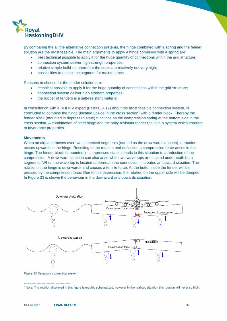
Movements
When an airplane moves over two connected segments (named as the downward situation), a rotation
occurs upwards in the hinge. Resulting to the rotation and deflection a compression force arises in the
hinge. The fender block is mounted in compressed state; it leads in this situation to a reduction of the
compression. A downward situation can also arise when two wave tops are located underneath both
segments. When the wave top is located underneath the connection, it creates an upward situation. The
rotation in the hinge is downwards and causes a tensile force. At the bottom side the fender will be
pressed by the compression force. Due to this depression, the rotation on the upper side will be damped.
In Figure 33 is shown the behaviour in the downward and upwards situation.
Figure 33 Behaviour connection system1
------------------------------------- 1 Note: The rotation displayed in this figure is roughly schematized; however in the realistic situation this rotation will never so high.
13 June 2017 FINAL REPORT 33
Final connection system 10.2
10.2.1 Cross section
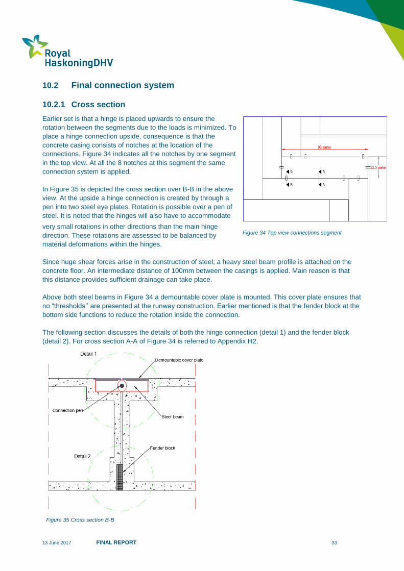
Earlier set is that a hinge is placed upwards to ensure the
rotation between the segments due to the loads is minimized. To
place a hinge connection upside, consequence is that the
concrete casing consists of notches at the location of the
connections. Figure 34 indicates all the notches by one segment
in the top view. At all the 8 notches at this segment the same
connection system is applied.
In Figure 35 is depicted the cross section over B-B in the above
view. At the upside a hinge connection is created by through a
pen into two steel eye plates. Rotation is possible over a pen of
steel. It is noted that the hinges will also have to accommodate
very small rotations in other directions than the main hinge
direction. These rotations are assessed to be balanced by
material deformations within the hinges.
Since huge shear forces arise in the construction of steel; a heavy steel beam profile is attached on the
concrete floor. An intermediate distance of 100mm between the casings is applied. Main reason is that
this distance provides sufficient drainage can take place.
Above both steel beams in Figure 34 a demountable cover plate is mounted. This cover plate ensures that
no “thresholds’’ are presented at the runway construction. Earlier mentioned is that the fender block at the
bottom side functions to reduce the rotation inside the connection.
The following section discusses the details of both the hinge connection (detail 1) and the fender block
(detail 2). For cross section A-A of Figure 34 is referred to Appendix H2.
Figure 34 Top view connections segment
Figure 35 Cross section B-B
13 June 2017 FINAL REPORT 34
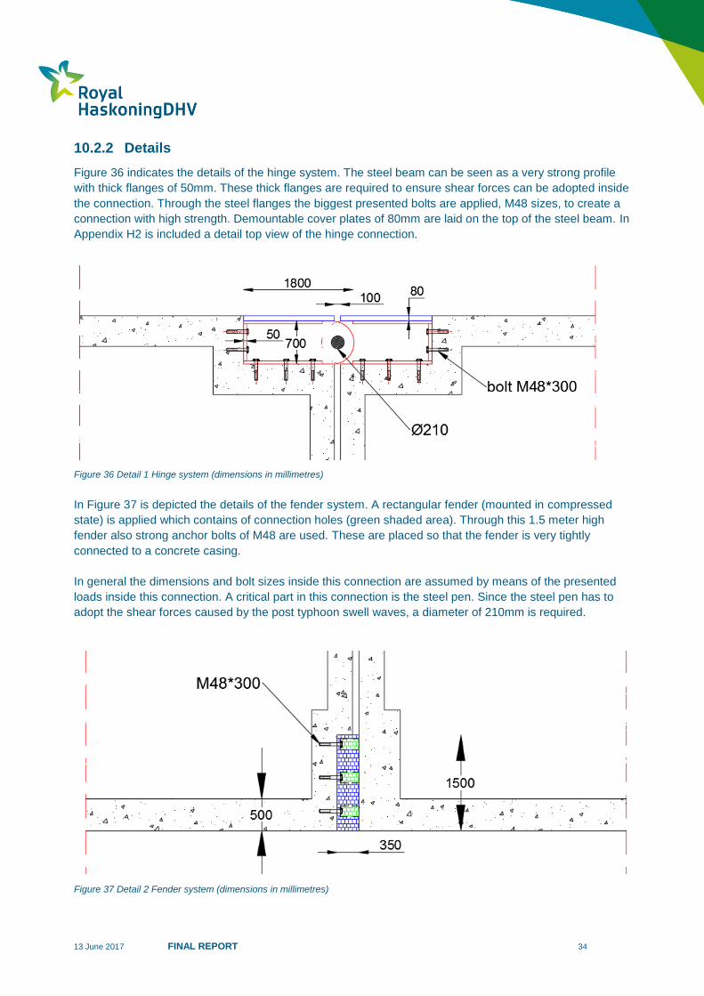
10.2.2 Details
Figure 36 indicates the details of the hinge system. The steel beam can be seen as a very strong profile
with thick flanges of 50mm. These thick flanges are required to ensure shear forces can be adopted inside
the connection. Through the steel flanges the biggest presented bolts are applied, M48 sizes, to create a
connection with high strength. Demountable cover plates of 80mm are laid on the top of the steel beam. In
Appendix H2 is included a detail top view of the hinge connection.
Figure 36 Detail 1 Hinge system (dimensions in millimetres)
In Figure 37 is depicted the details of the fender system. A rectangular fender (mounted in compressed
state) is applied which contains of connection holes (green shaded area). Through this 1.5 meter high
fender also strong anchor bolts of M48 are used. These are placed so that the fender is very tightly
connected to a concrete casing.
In general the dimensions and bolt sizes inside this connection are assumed by means of the presented
loads inside this connection. A critical part in this connection is the steel pen. Since the steel pen has to
adopt the shear forces caused by the post typhoon swell waves, a diameter of 210mm is required.
Figure 37 Detail 2 Fender system (dimensions in millimetres)
13 June 2017 FINAL REPORT 35
11 Concrete casing
Build-up segments 11.1
This chapter contains a summary of Deliverable I “Concrete Casings”; this part of this research is
conducted by Sjaak Bijl. Main goal of this study is to set the dimensions of the concrete casings whereby
these segments barely deformed by the normative post typhoon swell waves.
To ensure the segments are sufficient strong, a strength class has been chosen. All concrete casings are
located in Manila Bay; therefore the environmental concrete class can be named as XS. Within this class it
demands a strength class of C35/C45. A concrete casing consists out of an above and bottom floor.
Between these floors walls are placed. A freeboard of 2 meter is required for the floating segments.
Since an airplane causes a huge bending moment in the above floor of a concrete casing, intermediate
walls are placed. Walls inside the casing adopt the shear forces. Consequence is that bending moment
inside the floor is lower; however intermediate walls are quite expansive.
Inside the casing walls are places over 15 meters in the length direction and 5 meter in width direction.
Derived from these distances is set that the concrete casings have total dimensions of 22.5 meter width
and 90 meter long. This width length ratio correspondent to the herringbone grid structure, ratio 1:4.
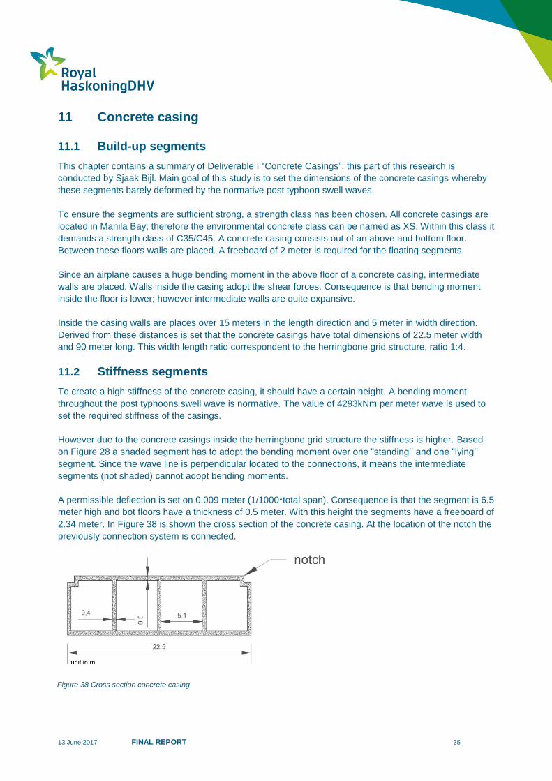
Stiffness segments 11.2
To create a high stiffness of the concrete casing, it should have a certain height. A bending moment
throughout the post typhoons swell wave is normative. The value of 4293kNm per meter wave is used to
set the required stiffness of the casings.
However due to the concrete casings inside the herringbone grid structure the stiffness is higher. Based
on Figure 28 a shaded segment has to adopt the bending moment over one “standing’’ and one “lying’’
segment. Since the wave line is perpendicular located to the connections, it means the intermediate
segments (not shaded) cannot adopt bending moments.
A permissible deflection is set on 0.009 meter (1/1000*total span). Consequence is that the segment is 6.5
meter high and bot floors have a thickness of 0.5 meter. With this height the segments have a freeboard of
2.34 meter. In Figure 38 is shown the cross section of the concrete casing. At the location of the notch the
previously connection system is connected.
Figure 38 Cross section concrete casing

13 June 2017 FINAL REPORT 36
12 Total costs VLFS
Since the sizes of the concrete casing are known and the connection system it is possible to make a cost
estimation of the Very Large Floating Structure. However additional elements such as the bridges and
mooring systems have to be part of the VLFS.
In Table 8 is estimated that the total price of a 3900 meter long and 450 meter width VLFS is 2133.5
million USD. The concrete casings largely (more than 80 percent) influence the total price of the VLFS.
To estimate the price of the concrete casing is used the knowledge about the heavy conditions in Manila.
Finally in consultation with (Peters, 2017) is decided to use a price of 600$/m3. An optimization of the
concrete casing dimensions could result in a smaller amount of connection systems. However it would
probably not lead to a considerable saving.
In Deliverable H “Connection system’’, Deliverable I “Concrete casing’’ and Deliverable J “Cost
comparison’’ the total cost estimation of the VLFS is elaborated in more detail.
Table 8 Cost estimation VLFS
Cost estimation Very Large Floating Structure
Compounds Quantity (num Price in million USD
Concrete casings 975 1795
Connection systems 3428 186.1
Bridges 3 150
Mooring system 12 2.44
Total price 2133.5
13 June 2017 FINAL REPORT 37
13 Cost comparison
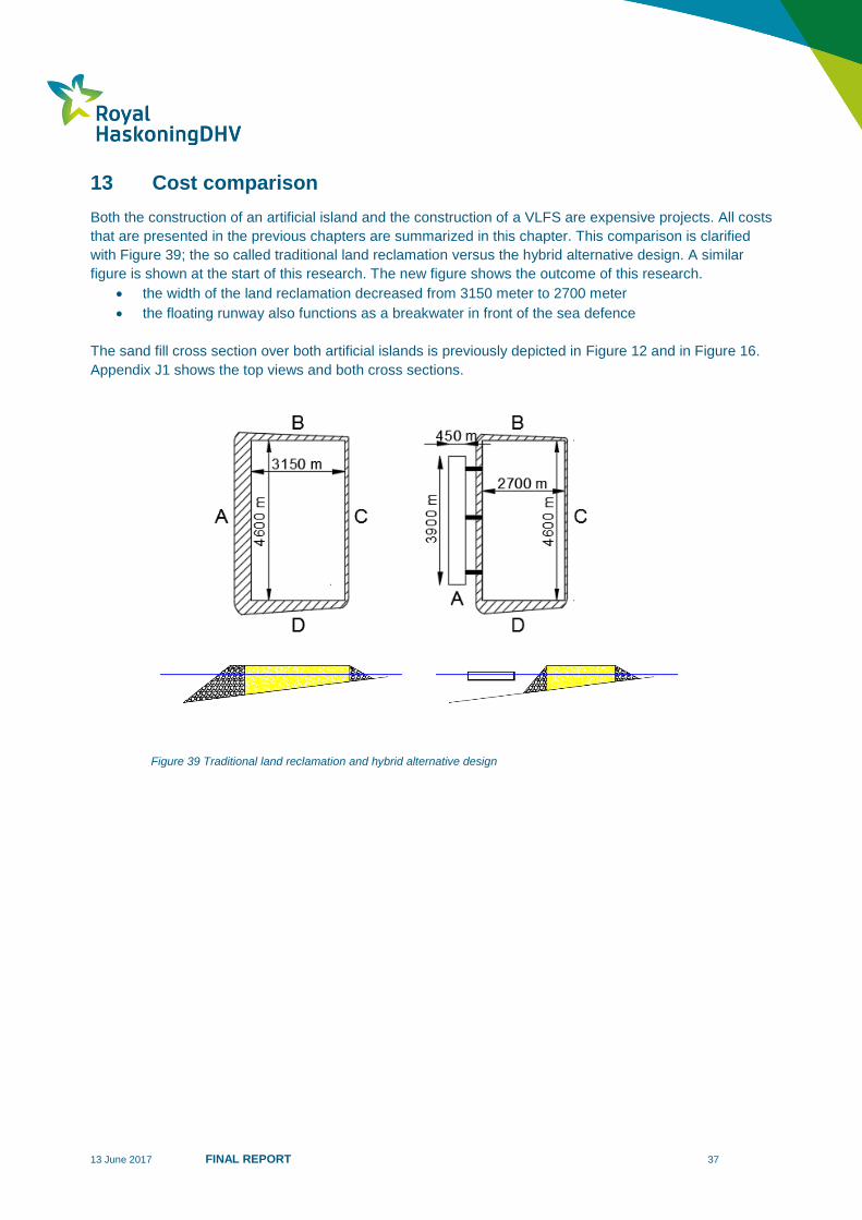
Both the construction of an artificial island and the construction of a VLFS are expensive projects. All costs
that are presented in the previous chapters are summarized in this chapter. This comparison is clarified
with Figure 39; the so called traditional land reclamation versus the hybrid alternative design. A similar
figure is shown at the start of this research. The new figure shows the outcome of this research.
the width of the land reclamation decreased from 3150 meter to 2700 meter
the floating runway also functions as a breakwater in front of the sea defence
The sand fill cross section over both artificial islands is previously depicted in Figure 12 and in Figure 16.
Appendix J1 shows the top views and both cross sections.
Figure 39 Traditional land reclamation and hybrid alternative design

13 June 2017 FINAL REPORT 38
In order to be able to compare both designs two tables are made. Table 9 indicates the total price of the
traditional land reclamation; whereas Table 10 shows the total costs of the hybrid alternative design.
Table 9 Total costs traditional land reclamation
Traditional land reclamation (net surface: 14490000 m2)
Component Quantity Unit price Total price (million USD) USD per net m2
Dredging 16.3*106 m
3 7 USD/m
3 114.1
Sand fill 256.9*106 m
3 9 USD /m
3 2312
Sea defence A 4600 m1
160000 USD/m1
736
Sea defence B 3150 m1
106000 USD/m1 333.9
Sea defence C 4600 m1 45000 USD/m
1 207
Sea defence D 3150 m1 234000 USD/m
1 739
Total price 4,442 310
The total price of the traditional land reclamation is 4,442 million USD. If there is sufficient sand available
in the borrow pit San Nicolas Shoal (because sand price is based on that borrow area) the square meter
price for this land reclamation in Manila Bay shall be approximately 310 USD / m2.
The alternative design includes a very large floating runway construction. By the application of this VLFS
the width of the land reclamation decreases to 2700 meter. The reduction in cross section (and thus of the
sand fill) is located at the deepest part of the Bay. This considerable decreases the amount of sand in the
reduced artificial island. Moreover the runway will function as breakwater in front of sea defence A. As a
result the cost of this sea defence decreases due to the sheltered location. It has been assessed that the
costs per running meter will reduce with at least 50%.
Table 10 Total price hybrid alternative design
Hybrid alternative design (net surface: 14175000 m2)
Component Quantity Unit price Total price (million USD) USD per net m2
Dredging 16.3*106 m
3 7 USD/m
3 114.1
Sand fill 204*106 m
3 9 USD /m
3 1836
Sea defence A 4600 m1
80000 USD/m1
368
Sea defence B 3150 m1
106000 USD/m1 333.9
Sea defence C 4600 m1 45000 USD/m
1 207
Sea defence D 3150 m1 234000 USD/m
1 739
VLFS 2133.5
Total price 5,617.4 396
13 June 2017 FINAL REPORT 39
0
2000
4000
6000
8000
10000
12000
14000
16000
18000
20000
0 5 10 15 20 25 30 35 40 45 50 55 60
To
tal p
rice (
mil
lio
n $
)
Unit price sand fill ($/m³)
Traditional landreclamation
Hybrid alternativedesign
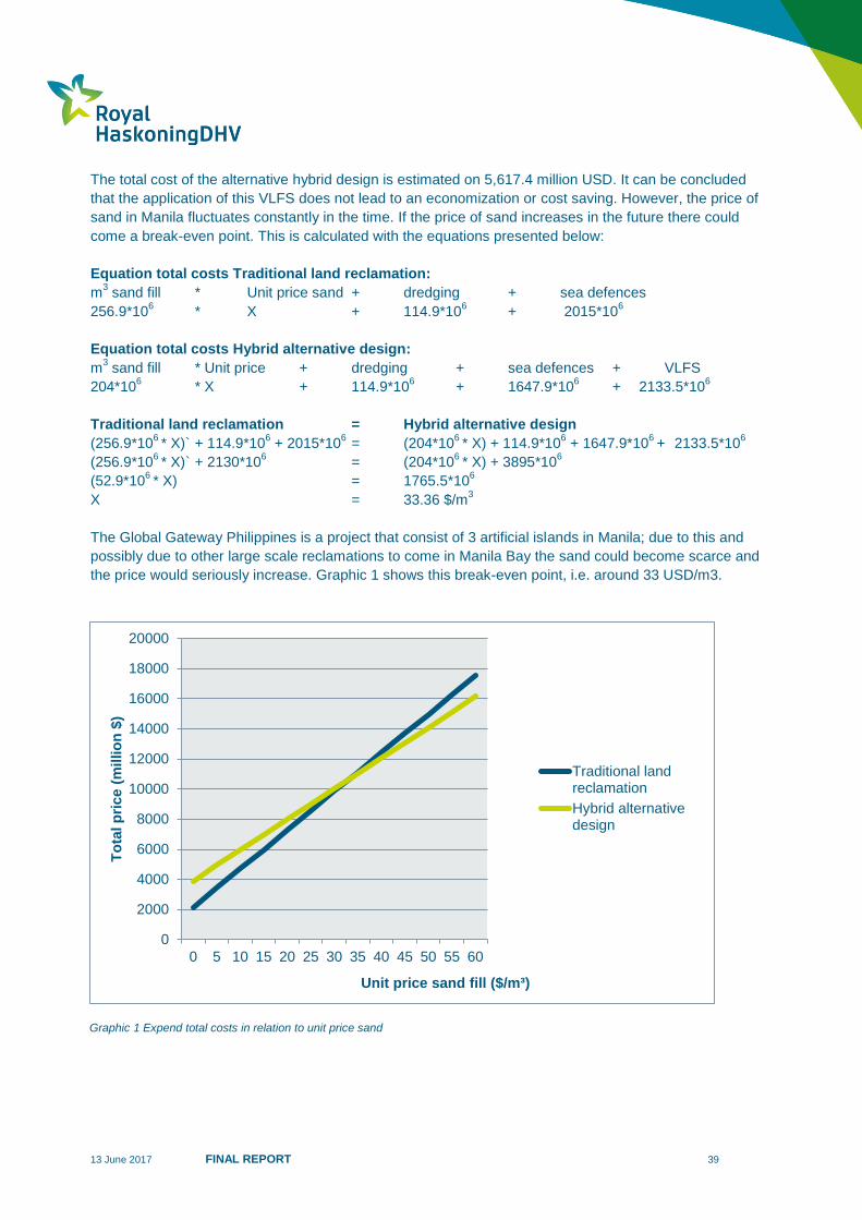
The total cost of the alternative hybrid design is estimated on 5,617.4 million USD. It can be concluded
that the application of this VLFS does not lead to an economization or cost saving. However, the price of
sand in Manila fluctuates constantly in the time. If the price of sand increases in the future there could
come a break-even point. This is calculated with the equations presented below:
Equation total costs Traditional land reclamation:
m3 sand fill * Unit price sand + dredging + sea defences
256.9*106 * X + 114.9*10
6 + 2015*10
6
Equation total costs Hybrid alternative design:
m3 sand fill * Unit price + dredging + sea defences + VLFS
204*106 * X + 114.9*10
6 + 1647.9*10
6 +
2133.5*10
6
Traditional land reclamation = Hybrid alternative design
(256.9*106 * X)` + 114.9*10
6 + 2015*10
6 = (204*10
6 * X) + 114.9*10
6 + 1647.9*10
6 +
2133.5*10
6
(256.9*106 * X)` + 2130*10
6 = (204*10
6 * X) + 3895*10
6
(52.9*106 * X) = 1765.5*10
6
X = 33.36 $/m3
The Global Gateway Philippines is a project that consist of 3 artificial islands in Manila; due to this and
possibly due to other large scale reclamations to come in Manila Bay the sand could become scarce and
the price would seriously increase. Graphic 1 shows this break-even point, i.e. around 33 USD/m3.
Graphic 1 Expend total costs in relation to unit price sand
13 June 2017 FINAL REPORT 40
14 Conclusion
The main question of this graduation research is as follows:
Is it possible to design an element within an airport layout as very large floating structure (VLFS)? And will
it result in costs savings compared to the total airport placed on land reclamation?
Based on the work done as part of this thesis, it is overall concluded that:
Runway
It is possible to design a Very Large Floating Structure in Manila Bay that is part of the airport extension.
The outcome is that the runway has the best possibilities to function as VLFS. Reason for this is the load
that acts upon this structure; the weight of planes on the structure spreads out over a big surface. The
load upon an apron/ramp area is higher since several planes are simultaneously placed upon a small
area.
Additional benefit of the big dimension of a floating runway is that the construction can serve as floating
breakwater that (partly) protects the reclamation behind it. This will lead to a smaller and less expensive
sea defence construction.
Elastic deformable VLFS
The floating runway construction in Manila Bay should be compiled out of a large number of relatively
small concrete casings that are closely connected with each other since it is impossible to build one rigid
structure with the dimensions of 3900 m long and 450 meter wide. This elastic deformable construction
can respond to the local wave conditions in Manila Bay and the planes landing upon the structure.
The wave conditions in Manila can be rather extreme because of frequently passing typhoons; this is the
main reason for leading to relatively high construction costs. The floating segments have to withstand
upward bending moments that reach 4,293 kNm per meter structure width. The placement of the
individual segments in a herringbone grid structure, connected by a hinge system leads to a strong and
flexible VLFS.
The concrete casings (building blocks) have a width-length ratio of 1:4. By placing two hinges at the long
side and one hinge at the short side of each building block, and next to that apply a herringbone
placement pattern for all blocks, it was found that the forces and rotations are best spread over the VLFS.
Costs
The construction cost of the VLFS becomes relatively high because of the big dimensions resulting from
the extreme design wave loads. Also the bridge connections and the mooring system increase the price
considerably. The order of magnitude of one floating square meter is assessed at 1200 USD gross (price
level 2017).
The application of a VLFS reduces the amount of sand that is needed to construct the (reduced) island; a
second saving arises since the sea defence at the lee side of the VLFS is relieved from extreme wave
attack. However, for the assumed sand fill price of 9 USD/m3, these advantages do not lead to savings for
the airport extension positioned in Manila Bay. The application of a VLFS as runway is presently estimated
to increase the total project cost with approximately 25%, compared to a traditional land reclamation
approach. If sand becomes scarce in the region of Manila this would lead to a higher price for sand. It was
found that there is a break-even point at 33 USD/m3.
13 June 2017 FINAL REPORT 41
15 Recommendations
Introduction 15.1
The floating runway construction that is theoretically designed in this report is an initial concept. No
prototype has been build which was suitable for scale tests in a laboratory. The design of the floating
runway construction in this report is used to make a comparison with traditional land reclamation in Manila
Bay. However, the developed concept of this elastic deformable floating construction can be applied in
almost every sea or lake around the world; likewise the floating “building ground” can be used for different
activities.
Since the construction of VLFS nowadays is still very rare a continuation of this research is useful and
required.
Design aspects 15.2
The following steps are recommended:
Tests with prototypes
The Rotterdam University of Applied Sciences has access to a wave simulator. By building a prototype at
reduced scale, tests with this structure can be made in this wave simulator. It is recommended to start with
2 prototypes; one structure with elements placed in a half stone pattern and the second one in
herringbone pattern ratio 1:4. In this way the reaction of both structures exposed to different waves can be
studied.
Seismic activity
The basis of design describes the seismic activity in the region Manila. The land reclamation is exposed to
the vibrations that arise through sliding plates of the earth crust. These movements can lead to damage
on the sea defence construction; the seismic activity is not included in the considerations involved with the
design of the sea defences around the artificial island. According to (Lem, 2017) a sea defence in earth
quake prone area is very complex and expensive. In order to establish a more accurate price for the island
the seismic activities have to be part of the full design.
Mooring System
The costs of the mooring system are roughly calculated in Deliverable J. The diameter of the pile is
estimated; the forces and impacts out of waves and moving airplanes that reach the mooring system have
not been studied in this thesis. Further in Deliverable F is concluded that the application of semi-
submersible segments relieve the mooring systems since an open structure is less sensitive to waves. A
more detailed research is needed to design the mooring system.
Bridge Connection
The bridge connections that are part of the alternative hybrid design are schematically elaborated in
Deliverable C and the costs are roughly calculated in Deliverable J. Important to notice is that more
detailed research is necessary weather it is possible to economically design and construct a bridge
construction between a floating runway and an island that can serve as taxiway for airplanes.

13 June 2017 FINAL REPORT 42
Optimizations 15.3
Dimensions concrete casing
The dimensions of the concrete casing are based on the intermediate distance of 15 m between the
internal support walls; 90 meter is a multiple of 15 meter. Probably it would be possible to build bigger
segments; bigger segments can result in a reduction of the number of connections. This can lead to a
significant cost saving of the total runway construction since the connection system is complex and
expensive.
Connection system
The connection system that is elaborated in this report is an important element in the functioning and
performance of the VLFS. In this thesis study a detailed analysis of the forces that arise inside this system
was not carried out. The dimensions of the hinge system and the fender which are similar for each
connection are roughly estimated based on engineering knowledge. More design work will be required in
order to come up with an efficient and reliable connection system.
13 June 2017 FINAL REPORT 43
16 Bibliography
Baijer. (2017).
Baijer, H. (2017, february). Airport Design Interview. (V. v.-S. Bijl, Interviewer)
Blok, I. R. (2012). Tabellen voor bouw en waterbouwkundigen. Eindhoven : ThiemeMeulenhoff.
Collepardi, I. R. (2003). Technical Contradictions in European Norm EN 206 for Concrete Durability .
London : Thomas Telford Limited .
Heath. (1897). The Works of Archimedes. Cambridge: Cambridge University Press Warehouse.
HNM / FBK. (2014, 3 21). Feasibility study for Philippine Global Gateway - Part IV Airport.
International Civil Aviation Organization. (2013). Aerodromes Annex 14.
Koekoek, M. (2010). Connecting Modulair Floating Structures. Delft.
Lem, C. v. (2017, March). Port Consultant . (Bijl, Interviewer)
Peters, D. I.-J. (2017, March ). Construction Floating elements. (S. Bijl, Interviewer)
Rijcken, T. (2004). Waterwonen . Delft: Delft Integraal.
RoyalHaskoningDHV. (2017). Pasay and Paranaque Reclamation Development .
Smits, M. (2017, 3 9). Land Reclamation. (Bijl, Interviewer)
Stive, R. (2015). Confidential Report . RoyalHaskoningDHV.
Stive, R. (2017).
Stybenex. (n.d.). www.stybenex.nl. Retrieved April 19, 2017, from Basis Informatie EPS:
http://www.hectar.nl/wp-content/uploads/2015/04/BasisbrochureEPS.pdf
Vonk, M. (2015). Toepassing vezel materiaal in ontwerp van korte verkeersbruggen. Amsterdam:
Hogeschool van Amsterdam.
Wang, C. (2010). Large Floating Structures Technological Advances. Singapore: Springer.
13 June 2017 FINAL REPORT 44
Appendices
Appendix A1 Bathymetry Project Site
Appendix A2 Typical cross section seabed
Appendix C2 Reference design of Manila Bay International Airport
Appendix C3 Floating structure
Appendix H1 Longlist Connection Systems
Appendix H2 Final Design Connection System
Appendix J1 Cross section Traditional land reclamation + Hybrid alternative design
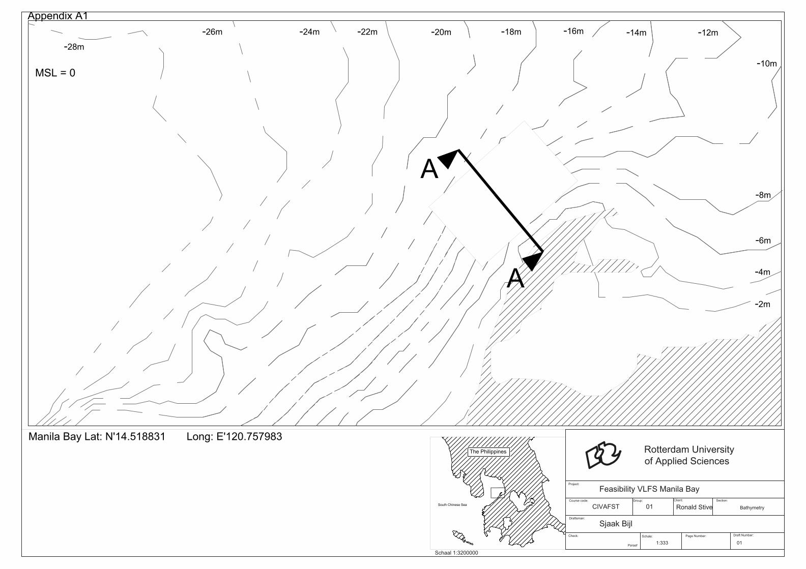
-22m -20m-18m
-16m
-14m
-10m
-8m
-6m
-4m
-2m
-24m-26m
-28m
-12m
MSL = 0
A
A
Appendix A1
South Chinese Sea
The Philippines
Check:
Paraaf
Schale:
Page Number:
Draft Number:
Project:
Course code: Group:
Client:Section:
Draftsman:
Rotterdam University
of Applied Sciences
Feasibility VLFS Manila Bay
CIVAFST 01Ronald Stive Bathymetry
1:333 01
Sjaak Bijl
Schaal 1:3200000
Manila Bay Lat: N'14.518831 Long: E'120.757983
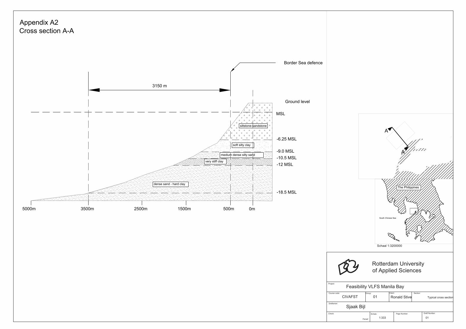
Ground level
3500m
-6.25 MSL
-9.0 MSL
-12 MSL
Cross section A-A
MSL
2500m 1500m 500m 0m
3150 m
5000m
-10.5 MSL
very stiff clay
siltstone-sandstone
medium dense silty sand
dense sand - hard clay
soft silty clay
-18.5 MSL
Border Sea defence
Appendix A2
South Chinese Sea
The Philippines
A
A
Check:
Paraaf
Schale:
Page Number:
Draft Number:
Project:
Course code: Group:
Client:Section:
Draftsman:
Rotterdam University
of Applied Sciences
Feasibility VLFS Manila Bay
CIVAFST 01
Ronald Stive Typical cross section
1:333 01
Sjaak Bijl
Schaal 1:3200000
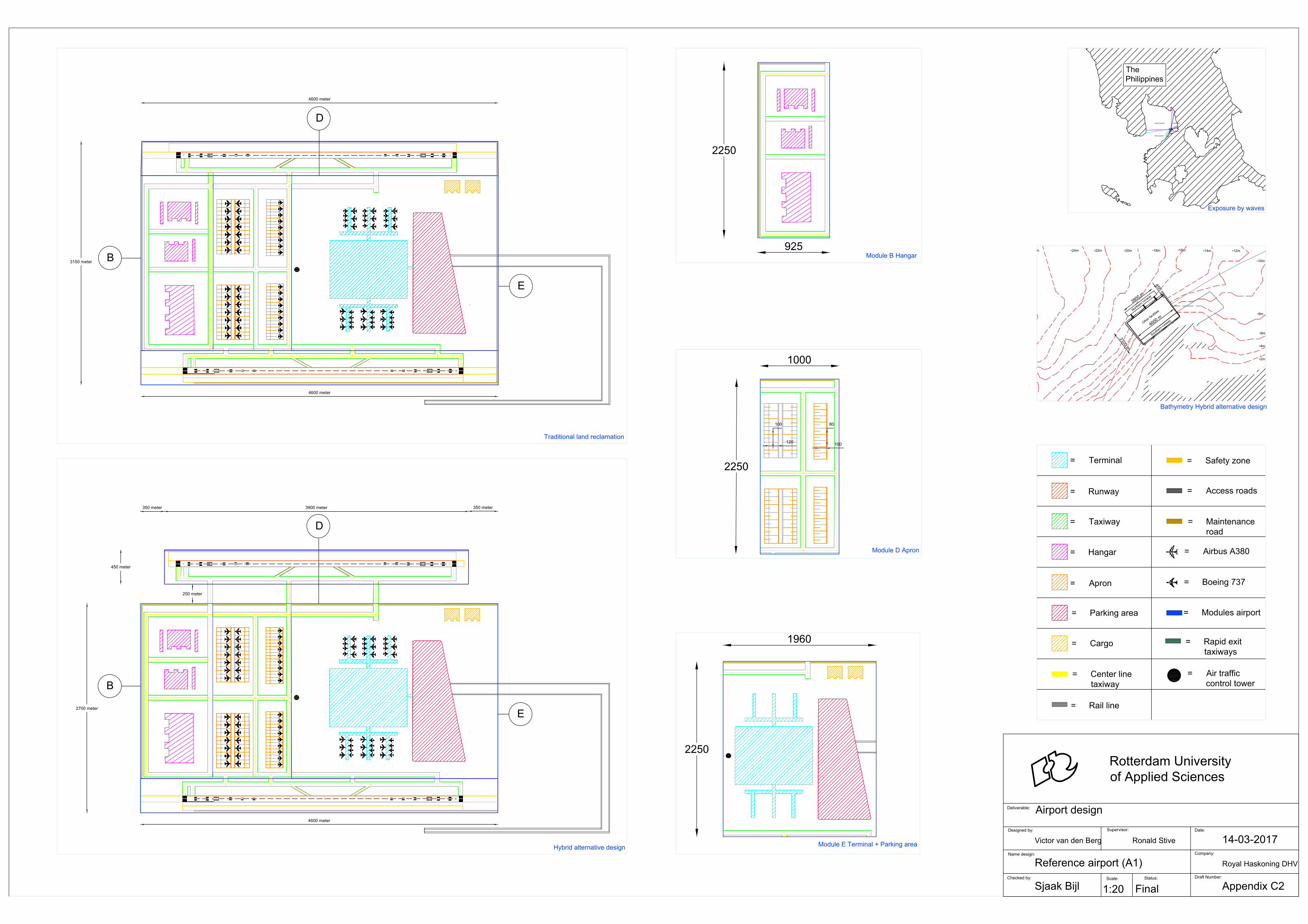
B
E
R
R
L
L
3150 meter
4600 meter
4600 meter
D
-22m -20m-18m
-16m
-14m-24m26m
-12m
-10m
-8m
-6m
-4m
-2m
N
o
r
t
h
e
r
n
r
u
n
w
a
y
2
7
0
0
m
4
6
0
0
m
S
o
u
t
h
e
r
n
r
u
n
w
a
y
O
t
h
e
r
f
a
c
i
l
i
t
i
e
s
3
9
0
0
m
4
5
0
m
ee
oke
Hard Exposed
The
Philippines
Fully exposed
Sheltered
Sheltered
= Terminal
= Runway
= Taxiway
= Hangar
= Apron
= Airbus A380
= Boeing 737
= Parking area
= Access roads
= Maintenance
road
= Safety zone
= Modules airport
= Center line
taxiway
= Rail line
= Rapid exit
taxiways
= Air traffic
control tower
= Cargo
1960
2250
Module B Hangar area
925
2250
1000
2250
100
120
80
100
E
R
R
L
L
D
2700 meter
250 meter
3900 meter
450 meter
4600 meter
350 meter350 meter
B
Module D Apron
Module B Hangar
Module E Terminal + Parking area
Traditional land reclamation
Checked by:
Scale:
Status:
Draft Number:
Deliverable:
Designed by:
Supervisor:
Date:
Name design:
Rotterdam University
of Applied Sciences
Company:
Airport design
Victor van den Berg
Sjaak Bijl
Final
Reference airport (A1)
Ronald Stive
Appendix C2
Royal Haskoning DHV
14-03-2017
1:20
Hybrid alternative design
Exposure by waves
Bathymetry Hybrid alternative design

1. Steel cable
2. Hinge (middle position)
4. Fender
3. Hinge combined with spring
Ruber / synthetic material
5. Springs
6. Puzzle
Ruber / synthetic material
7. Pin connection
Steel rod with surrounded rubber layer
Checked by:
Scale:
Status:
Draft Number:
Deliverable:
Designed by:
Supervisor:
Date:
Name design:
Rotterdam University
of Applied Sciences
Company:
Connection System
Victor van den Berg
Sjaak Bijl
Final
Longlist Connection Systems (A3)
Ronald Stive
Appendix H1
Royal Haskoning DHV
18-05-2017
1:20
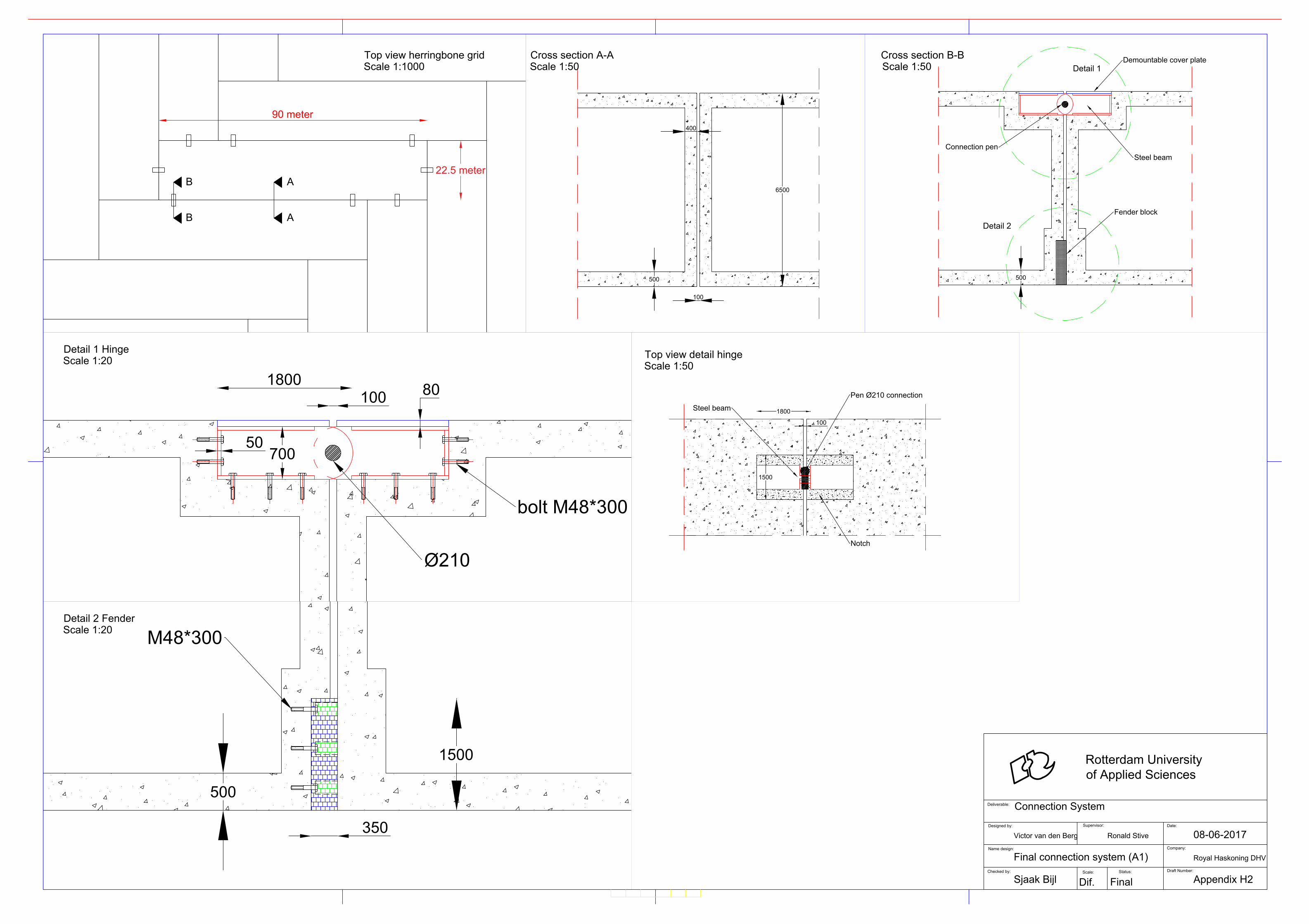
90 meter
22.5 meter
A
A
B
B
6500
500
400
100
500
Detail 1
Detail 2
Steel beam
Connection pen
Demountable cover plate
Fender block
1800
700
80
Ø210
100
50
bolt M48*300
500
M48*300
1500
350
Pen Ø210 connection
Steel beam
100
1800
1500
Notch
Scale 1:1000
Cross section A-ATop view herringbone grid Cross section B-B
Scale 1:50 Scale 1:50
Scale 1:20
Detail 1 Hinge
Scale 1:20
Detail 2 Fender
Scale 1:50
Top view detail hinge
Checked by:
Scale:
Status:
Draft Number:
Deliverable:
Designed by:
Supervisor:Date:
Name design:
Rotterdam University
of Applied Sciences
Company:
Connection System
Victor van den Berg
Sjaak Bijl
Final
Final connection system (A1)
Ronald Stive
Appendix H2
Royal Haskoning DHV
08-06-2017
Dif.
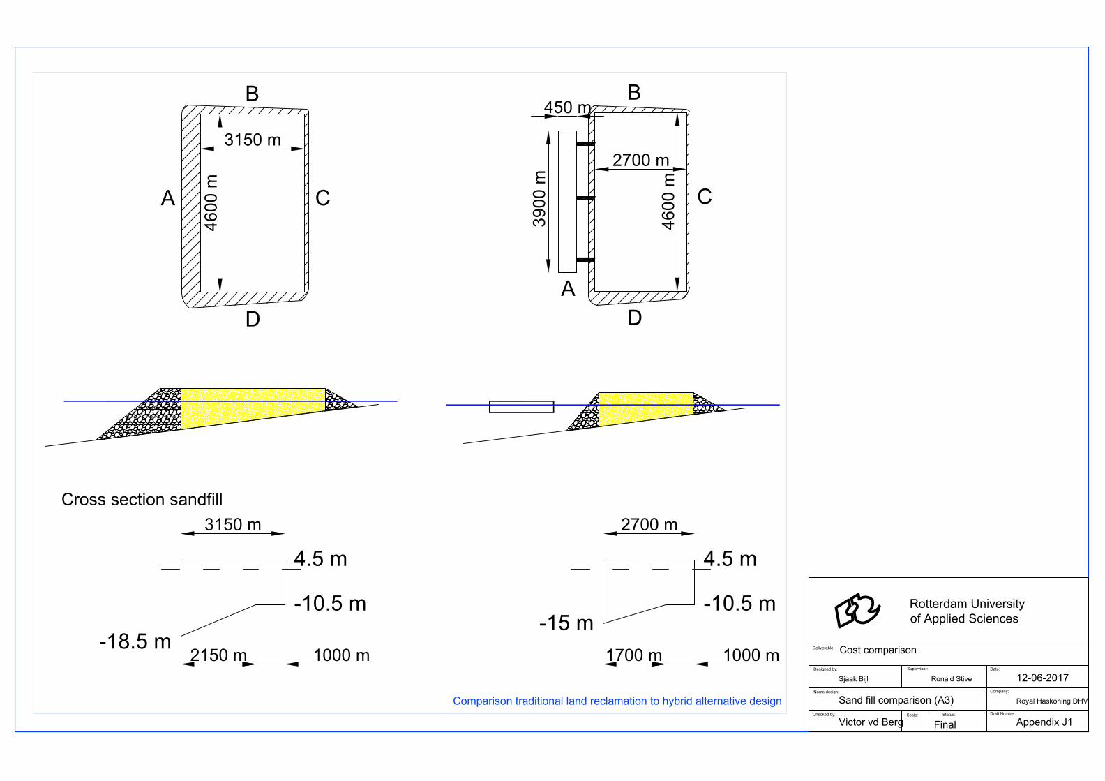
39
00
m
450 m
46
00
m
3150 m
2700 m
A
B
C
D
A
B
C
D
46
00
m
Traditional Land reclamation Hybrid Alternative Design
-10.5 m
-18.5 m
4.5 m
2150 m
3150 m
1000 m
-10.5 m
-15 m
4.5 m
1700 m
2700 m
1000 m
Cross section sandfill
Checked by:
Scale:
Status:
Draft Number:
Deliverable:
Designed by:
Supervisor:Date:
Name design:
Rotterdam University
of Applied Sciences
Company:
Cost comparison
Sjaak Bijl
Victor vd Berg
Final
Sand fill comparison (A3)
Ronald Stive
Appendix J1
Royal Haskoning DHV
12-06-2017
Comparison traditional land reclamation to hybrid alternative design

3900m
2700m
250m
450m
4600m
2250m
MSL+ 4.50m
Sea defence construction
Sea defence width
Total footprint
Bed level Varies
Typical Cross section A-A
450m
LAT -1.04m
MSL +0.96m
Bridge connection
(taxiway)Floating structure h = 2m
Aprons
Taxiway
Runway
236m 14m
75.5m
450m
A
B
D
A AA
Very Large F
loating S
tructure
Airport
Layout
Sea
defence
C
L
L
3900
450
190
100
80
120
30 degrees
150
60
Touchdown zoneTouchdown zone
236m
14m
MSL +4.50m
LAT -1.04m
MSL +0.96m
Floating structure Bridge connection Fixed airport
MSL+ 4.50
Sea defence construction
Sea defence width
Total footprint
Bed level Varies
Seadefense width
Typical Cross section B-B
MSL
925m
Hangar
400m
700m1000m 1960m
Apron
Taxiway
Terminal
Parking area
Top view airport
Scale 1:100
Cross section A-A
Scale 1:1
Location airport
Floating structureChecked by:
Scale:
Status:
Draft Number:
Deliverable:
Designed by:
Supervisor:Date:
Name design:
Rotterdam University
of Applied Sciences
Company:
Airport design
Victor van den Berg
Sjaak Bijl
Final
Floating structure (A3)
Ronald Stive
Appendix C3
Royal Haskoning DHV
14-03-2017
1:20
Bridge connection
Scale 1:20
Cross section B-B
Scale 1:1