Embed Size (px)
Citation preview
FINAL REPORT ON A STUDY OF
METEOROID IMPACT PHENOMENA
Prepared for:
/ /
NATIONAL AERONAUTICS AND SPACE ADMINISTRA TION
FINAL REPORT
W. J. Rae and H. P. Kirchner
Contract No. NAS 3-2121
CAL Report No. RM-1655-M-4
February 1963
CORNELL AERONAUTICAL LABORATORY, INC.
OF CORNELL UN I VERSITY , BUFFALO 21 , N . Y .
https://ntrs.nasa.gov/search.jsp?R=19630007011 2018-07-18T20:32:12+00:00Z
co<x' _-f
CORNELL AERONAUTICAL LABORATORY, INC.
BUFFALO 21, NEW YORK
REPORT NO. RN-IB55-M-_
FIHAL REPORT ON
A STUDY OF METEOROID IMPACT PHENOMENA
FEBRUARY 1963
CONTRACT NO, NAS 3-2121
PREPARED BY:
PREPARED FOR
NATIONAL AERONAUTICS AND SPACE ADMINISTRATION
_J__.__ _, __William ]. Rae
Henry__Ki rchner
APPROVED BY:
FOREWORD
This report presents the results of a theoretical study of hypervelocity
impact into semi-infinite targets. The work has been sponsored by the Lewis
Research Center of the National Aeronautics and Space Administration under
Contract No. NAS 3-2121, in support of their Research Program to developa
structurally adequate radiator for use on space vehicles. In order to provide
the desired support, diverse aspects of the meteoroid impact problem have
been examined. This report collects all pertinent data obtained under the
contract into one reference work which will be useful, as such, for NASA's
program and also for background for further research on hypervelocity impact
phenomena.
Technical monitoring was provided by Mr. Robert J. Denington and
Mr. James J. Kramer, to whom the authors are very grateful for numerous
helpful suggestions.
The approach on which this study is based was suggested originally by
Dr. Franklin K. Moore of this Laboratory, and was later elaborated by Dr.
Walter E. Gibson. The authors have continued to benefit from frequent dis-
cussions with Drs. Moore and Gibson, and in addition, valuable contributions
have been made by Mr. HowardA. Scheetz and Dr. NormanS. Eiss.
Special thanks are due to Mr. Harold M. Rosenbaum, who very ably
handled the programming of various calculations for an IBM 704, and to
Miss Marcia J. Williams, Miss Sarah J. Gerac[, Mr. GirardA. Simons,
and Mr. John R. Moselle, who prepared the figures and carried out the
associated calculations.
The analyses presented below embrace both fluid-mechanical and solid-
mechanical considerations. The former are the work of the first author, while
the latter are due to the second.
RM- 1655-M- 4 i
/_ _ _ $ ABSTRACT
This report presents an analytical treatment of the process of crater
formation in semi-infinite targets as a result of impact by hypervelocity
projectiles. The results are achieved by using blast-wave theory to treat
the fluid-rnechanical phase of the target response, together with a simple
means of accounting for the target strength in the later stages of the cratering
process. The crater-size formula finally deduced is quite simple. To enable
the interested reader to apply it without following a lengthy derivation, the
formula and its application are presented in a separate section.
The theory in its present form is found to agree reasonably well with
relatively low-speed experiments, and the agreement can be expected to
improve at higher impact speeds. The simple crater-size formula reveals
that the kinetic energy of the impacting particle is a controlling parameter
and that the dynamic strength of the target is the factor most effective in
limiting penetration.
Careful attention is paid to energy and momentum conservation, and
the momentum of the incident particle is found to play a relatively minor
role. The attendant physical and mathematical reasons are discussed,
including their implications on experiment.
Requests for copies of this report should be referred to:
National Aeronautics and Space Administration
Office of Scientific and Technical Information
Washington Z5, D. C.Attn: AFSS-A
RM- 1655 -M-4 ii
It
TABLE OF CONTENTS
FOREWORD
AB ST RA C T
LIST OF FIGURES
LIST OF TABLES
LIST OF SYMBOLS
INTRODUCTION
B LAST -WAVE SOLUTION
A. ) Fluid-MechafHcal Model
Basic Equations
Symmetry A s sumptions
Boundary C ondition s
Similarity A s sumption
B.)
1.)
2.)
3.)
4.7
5.)
6.)
7.7
8.)
Pe rfect- Gas Approximation
Procedure for Finding
Conservation of Energy and Momentum
Final Form of the Problem Posed
Spherically-SyTnmetric (Constant-Energy) Solution
i. ) Solution for _s (_:)
2. ) Crater Formula
3. ) Scaling Laws
4. ) Comparison with Other Theories
A symmetric Solutions
1. ) Two-dimensional Solution
2.) Criterion for Choosing N
c.)
i
ii
vi
viii
xi
1
3
3
3
5
6
8
11
15
2O
21
23
23
30
34
37
39
39
43
RM-1655-M-4 iii
II.
3)
4.)
5.)
6.)
7.)
8.)
9-.)
Approximations for _" (_ J
Results for _I = i, K = 1, I0
Comparison with the Symmetric Solution
Isolation of the Sonic Point
One-dimensional Solution
Determination of N
Simultaneous Conservation of Energy and
Momentum
BOUNDARIES FOR APPLICATION OF THE BLAST-WAVE
ANALYSIS
A. ) Meteoroids and Space Vehicles
B. ) Energy Transformation during Impact
C. ) Stress-Wave Velocities in Solids
i.) Elastic Stress Waves
2. ) Plastic Stress Waves
3. ) Shock Waves in Solids
D. ) Collisions Involving Porous Bodies
i.)_ Case I - Impacts of Porous Meteoroids Against
Solid Surfaces
2. ) Cases II - V
E. ) The Crater Wall Criterion
1. ) The Intrinsic Strength of Crystals
2. ) The Influence of Shear Strength on Crater
Formation
3. ) The Dynamic Shear Modulus and Intrinsic
Strength of Structural Materials
4. ) Variation of the Dynamic Shear Modulus with
Temperature and Pressure
43
45
46
49
52
54
56
65
65
67
71
71
74
75
77
77
79
80
8O
83
85
86
RM- 1655-M-4 iv
III. SUMMARY AND ILLUSTRATIVE CALCULATIONS
1. ) Review of the Analysis
2. ) Illustrative Calculations
CONCLUDING REMARKS
REFERENCES
APPENDIX A
APPENDIX B
APPENDIX C
90
9O
95
98
101
II0
112
116
RM-1655-M-4 v
Figure No.
1
2
3
4
5
6
7 a-j
8
9 a-b
I0
II
12
13
14 a-f
15 a-e
16
17
LIST OF FIGURES
Equation of State of Iron
Typical Isentropes of Iron
Effective _" for Normal Shock Waves in Iron
Hugoniot Curves for Iron and Lead
Effective y' for Lead Targets Struck byIron
Attempted Spherically-Symmetric Solution
Distribution of Density, Particle Velocity, andPressure for Constant-Energy, Spherically-Symmetric Blast Waves at Various Values of f
The Function Ira(9")
Measured Shock-Wave Time-Histories Com-
pared with Blast-Wave Prediction
Crater-Size Prediction by the Constant-Energy, Effective- 7" Solution
Constant-Energy, Effective- g Solution forCraters Formed by Steel Striking Lead
Constant-Energy, Effective- _' Solution forCraters Formed by Iron Striking Iron
Constant-Energy, Effective- _ Solution forCraters Formed by Aluminum Striking Copper
The Function _'(V) for Various Projectile-
Target Combinations
Centerline Distributions of Density, Pressure,and Velocity at Various Values of 7" , K = 10,a.=l
Centerline Solution for _ = 4, K = 1, a. = 1
Taylor Solution Compared with CenterlineSolution
119
120
121
1ZZ
123
124
125
135
136
137
138
139
140
141
144
149
150
RM-1655-M-4 vi
18
19
20
21
22
23
24
25
26
27
28
29
Sonic-Line Crossing in the _ Plane
Dependence of N on 7" for One-DimensionalBlast Waves
One-Dimensional Blast-Wave Solutions,
7" =1.4
The Function Io(_' )
Power-Density Rating for Shock Waves inIron
Power-Density Rating for Materials Whose
Hugoniot is Described by _s = ¢" + su I
Blast-Wave Prediction of Craters Formed
in Iron by Deposition of Energy E overArea A in Time _'
Hugoniots for Normal and Porous Iron
Pressure vs. Particle velocity for Normaland Porous Iron
Hugoniots for Normal and Porous Iron
Schematic Shock Compression Diagram ofPorous and Non-Porous Material
Ejection of Material from a Crater
151
152
153
154
155
156
157
158
159
160
161
162
RM-1655-M-4 vii
Table Number
2
3
4
5
6
7
O
LIST OF TABLES
Hugoniot Data
N(_') for One-dimensional Blast Waves
Stages of Energy Transformation during
Impact
Physical Properties of Selected Solids
Variation of Elastic Constants with Pressure
Energy Distribution in Porous and Non-
Porous Bodies
Compressive Strength of Materials under
Hydrostatic Pressure
Intrinsic Strength based upon Shock-V, faw_Data
163
164
165
166
167
168
169
170
RM-1655-M-4 viii
_, K
G
e
E
C_
H(q)
_ (i)
_o
N
P
P
ID
tr, 0
R_
S
t
T
LIST OF SYMBOLS
parameters in assumed pressure distribution
limiting speed of a weak shock
projectile diameter
internal energy per unit mass
total energy
total energy per unit area
dimensionle s s pressure
dimensionless internal energy
shear modulus
function defined by Eq. (96)
function defined by Eq. (66)
neglected mass per unit area
exponent describing shock speed R s _ t
pressure
total momentum
total momentum per unit area
pressure level at which solution is terminated
velocity vector
spherical coordinates
shock radius
entropy; also dimensionless parameter in t_s = C + 5U l
time after impact
temperat ure
velocity components in r" and 0 directions
RM-I 655-M-4 ix
V
Y
a.W)
I1¢,
y
:#
P
0"
"r(,-i)
a.)
()o(),
(),,
().( 4(Y
impact speed
Young' s modulus
function appearing in Mie-Gr{ineisen state equation
similarity coordinate, r/_ s
dimensionless r" -component of velocity
Gr{inei sen factor
constant used to approximate I+ F(_)
Poisson's ratio
dimensionless density
mass density
shear stress
centerline value of tangential velocity gradient, 2 -_- CO,O)
dimensionless tangential velocity component
undisturbed value, before impact
value behind the shock
value at the shock
cohesive part
evaluated on the Hugoniot
pertains to the projectile
indicates sonic-point value
RM-1655-M-4 x
INTRODUCTION
The purpose of this research has been to achieve an analytical
description of the phenomena brought into play when a high-speed projectile
strikes a semi-infinite target. The extremely high pressures generated
under the conditions of high-speed impact suggest a fluid-mechanical
model for describing the motion of the impacted medium. Numerical
solutions of the resulting equations have been published for specific cases.
This report describes analytic results obtained by applying blast-wave
theory to solve these fluid-mechanical equations. The spirit of the approach
is to simplify the analysis wheraver possible by making certain approxima-
tions to the true physical situation. The aim in doing so is to achieve
generality and simplicity of the results, at the expense of some exactness
in describing the details of the solution.
The report is divided, essentially, into two parts. The first of these,
Part I, describes the blast-wave solution for the early, high-pressure phase
of the motion. The second, Part II, discusses the solid-mechanical aspects
of the problem, particularly from the point of view of the target strength.
Part III summarizes the theory, and illustrates the use of the crater-size
formula by working out several examples. To facilitate quick application,
this section is so written that it may be read independently of the remainder
of the report.
In Part I, two types of solution are described. In one, which permits
spatial variations in two directions, it is possible to conserve both the energy
and momentum of the system. The other solution, which allows only for
variations in the radial direction, and conserves only the total energy, is a
RM- 1655-M-4 1
modification of the classical Taylor solution for an instantaneous point
release of energy. Approximate solutions of the former type are found to
be very close to the vastly-simpler Taylor solution in all important respects.
The analytical results that lead to this conclusion are described, and the
physical reasons that underlie this phenomenon are discussed. The
significance of this finding is to indicate why the sirnpler Taylor solution
may be used.
Part II is devoted generally to a study of the limits of the blast-wave
analysis, and describes some of the detailed phenomena that may be expected
during the early stages of the impact process. In addition, particular
attention is paid to the later stages of crater formation, during which the
plastic and elastic response of the target must be considered. An important
part of this work is to identify the material-strength level at which the blast-
wave solution is to be terminated. The meaning of this as a crater-formation
criterion is discussed.
The concluding remarks summarize the advances that have been made,
and indicate the areas where improvements in the theory can be expected.
RM-1655-M-4 2
I. BLAST-WAVE SOLUTION
This portion of the report presents the solutions obtained for the target
response in the fluid regime. Section A, below, describes the fluid-mechanical
model, listing the several approximations that are fundamental to a blast-wave
solution. The second and third sections then present two different types of
solution of the fluid-dynamical equations.
A. Fluid-Mechanical Model
To derive an analytic description of hypervelocity impact, two steps are
taken. The first is to treat the target material as a compressible fluid, while
the second is to simplify the resulting equations in such a manner that a simple
solution is possible. Similarly, below, the basic equations appropriate to the
compressible-fluid approximation are first discussed. Then described are
the key mathematical simplifications used, and the restrictions which they
imply. The last two sub-sections summarize the formulation of the problem.
1. Basic Equations. When a particle strikes a target surface at high
speed, large amounts of energy and momentum are quickly deposited over a
very small portion of the surface. This release drives a strong shock wave
into the target, generating extremely large pressures, typically measured in
megabars. Because these pressures are so large compared with the mate-
rial strength, even at high strain rates, one is led to the approximation
that the impacted medium behaves like an inviscid, compressible fluid. In
actual fact, the justification for such an approximation is not provided by the
magnitude of the pressures themselves, but must come from a consideration
of their gradients. Consider a small mass element
RM-1655-M-4 3
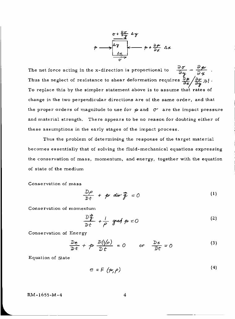
a0- A__+_-
7(r
The net force acting in the x-direction is proportional to _°_ _-
_. _,_ •Thus the neglect of resistance to shear deformation requires _ / oo_>_l
_/_ -To replace this by the simpler statement above is to assume that rates of
change in the two perpendicular directions are of the same order, and that
the proper orders of magnitude to use for 7_and (7" are the impact pressure
and material strength. There appears to be no reason for doubting either of
these assumptions in the early stages of the impact process.
Thus the problem of determining the response of the target material
becomes essentially that of solving the fluid-mechanical equations expressing
the conservation of mass, momentum, and energy, together with the equation
of state of the medium
Conservation of mass
opDt
Conservation of momentum
Conservation of Energy
_- ÷_
Equation of State
e
/ (z)=o
:bs (3)z,.,._ o o,.. =oDf ])t"
=F (rip) (4)
RM-1655-M-4 4
$ the entropy, and _ the velocity vector.
Here /9 denotes the density, -_ the pressure,
per unit mass,
D/J_t is the convective derivative
in which t is the time and
the internal energy
The symbol
(5}
V the gradient operator. It should be noted
that the assumption of an inviscid fluid has been made by setting the right-
hand side of Eq. {2} equal to zero. If shearing forces were to affect the motion,
they would have to be added to this equation. Consistent with this approximation,
energy changes arising from viscous dissipation and heat conduction are omitted
from the energy equation. In addition, energy changes due to radiation and
chemical change are also neglected. Thus, the conservation of energy simply
states that, for each element of mass, changes of internal energy, _ , are
balanced by changes in the flow-work term, -_ _ (//_) Alternatively,
this may be expressed by stating that the entropy of a given mass element does
not change, after it has been processed by the shock.
Finally, it should be noted that the use of an equation of state implies
an assumption of thermodynamic equilibrium.
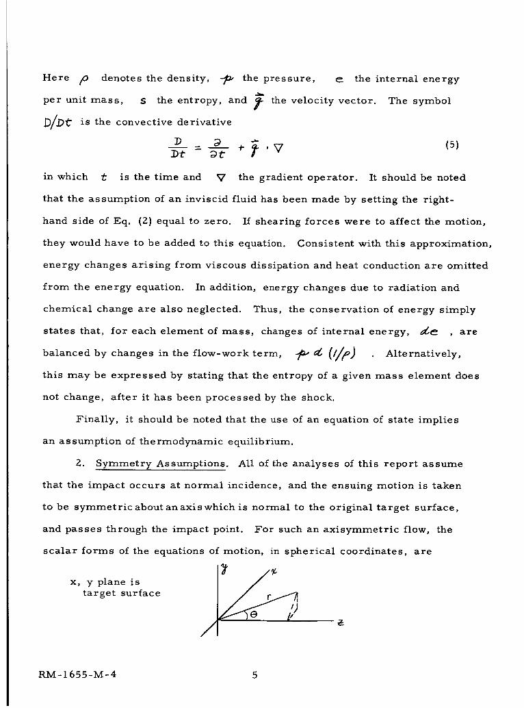
2. Symmetry Assumptions. All of the analyses of this report assume
that the impact occurs at normal incidence, and the ensuing motion is taken
to be symmetric about anaxiswhich is normal to the original target surface,
and passes through the impact point. For such an axisymmetric flow, the
scalar forms of the equations of motion, in spherical coordinates, are
x, yplane is _'0/_target surface
/
RM-1655-M-4 5
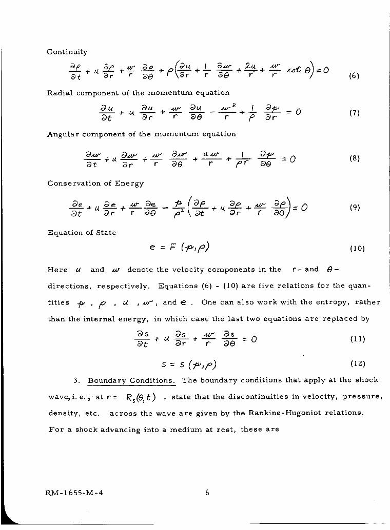
Continuity
@t -'F _0 r _ +--_-" +7- (6)
Radial component of the momentum equation
(7)
Angular component of the momentum equation
(8)
Conservation of Energy
(9)
Equation of State
: F (,o)
Here _X and x_r denote the velocity components in the r- and 8-
directions, respectively. Equations (6) - (I0) are five relations for the quan-
tities _ , /P , b4 , _', and e One can also work with the entropy, rather
than the internal energy, in which case the last two equations are replaced by
_s oqs _ Dso_---'t-+ /'(-_r + r _0 - 0 (11)
s = s (iz)
3. Boundary Conditions. The boundary conditions that apply at the shock
wave, i. e. _- at r = /_s_gs_) , state that the discontinuities in velocity, pressure,
density, etc. across the wave are given by the Rankine-Hugoniot relations.
For a shock advancing into a medium at rest, these are
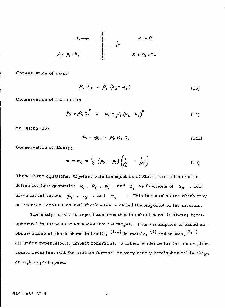
t_t ---_ Uo: 0
_o_ _o;_o
Conservation of mass
Po_s = p, (",-.,) (13)
Cons e rvation of momentum
z 2
= _,÷p,C,,s-_,,) (14)
or, using (13)
Conservation of Energy
- _o -- _o _, _, (14a)
These three equations,
_,- _o = -_ (Po-,-_,) ,,:, (is)
together with the equation of State, are sufficient to
define the four quantitLes b(I ' PI ' _l , and el as functions of ¢X$ , for
given initial values _o ' mo , and e ° This locus of states which may
be reached across a normal shock wave is called the Hugoniot of the medium.
The analysis of this report assumes that the shock wave is always hemi-
spherical in shape as it advances into the target. This assumption is based on
observations of shock shape in Lucite, (1, Z) in metals, (1) and in wax, (3, 4)
all under hypervelocity impact conditions. Further evidence for the assumption
comes from fact that the craters formed are very nearly hemispherical in shape
at high impact speed.
RM-1655-M-4 7
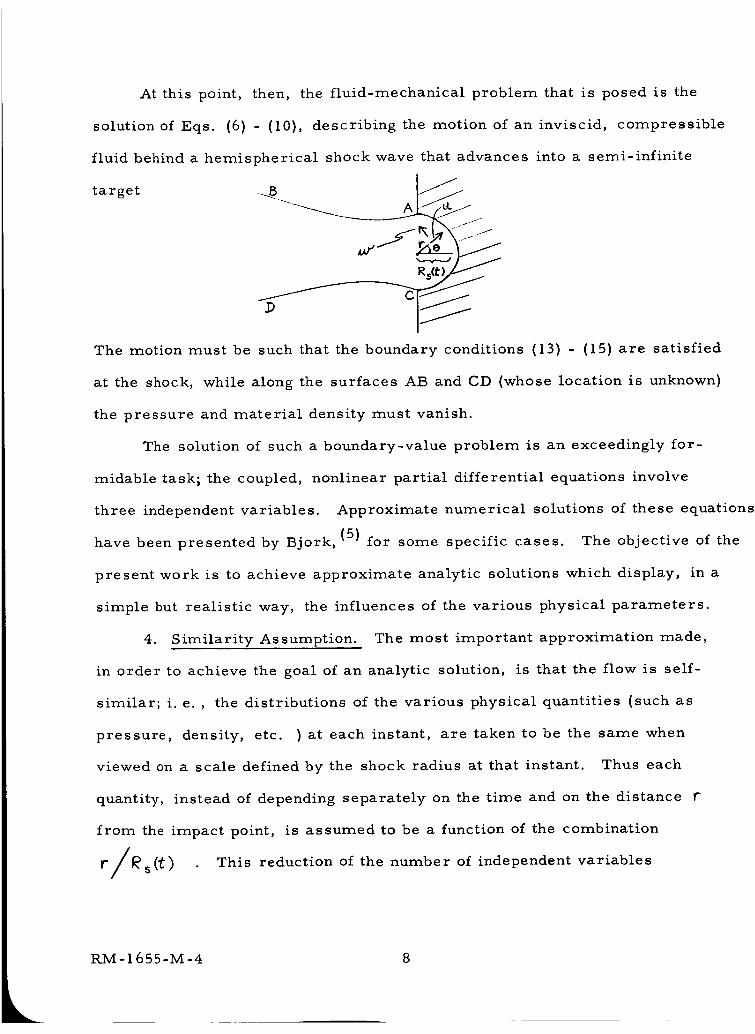
At this point, then, the fluid-mechanical problem that is posed is the
solution of Eqs. (6) - (I0), describing the motion of an inviscid, compressible
fluid behind a hemispherical shock wave that advances into a semi-infinite
target ...B
The motion must be such that the boundary conditions (13) - (15) are satisfied
at the shock, while along the surfaces AB and CD (whose location is unknown)
the pressure and material density must vanish.
The soIution of such a boundary-value problem is an exceedingly for-
midable task; the coupled, nonlinear partial differential equations involve
three independent variables. Approximate numerical solutions of these equations
have been presented by Bjork,(5) for some specific cases. The objective of the
present work is to achieve approximate analytic solutions which display, in a
simpie but realistic way, the influences of the various physical parameters.
4. Similarity Assumption. The most important approximation made,
in order to achieve the goal of an anaIytic solution, is that the flow is self-
similar; i. e., the distributions of the various physical quantities {such as
pressure, density, etc. ) at each instant, are taken to be the same when
viewed on a scale defined by the shock radius at that instant. Thus each
quantity, instead of depending separately on the time and on the distance r
from the impact point, is assumed to be a function of the combination
r/_(t) This reduction of the number of independent variables/
kRM- 1655-M-4 8
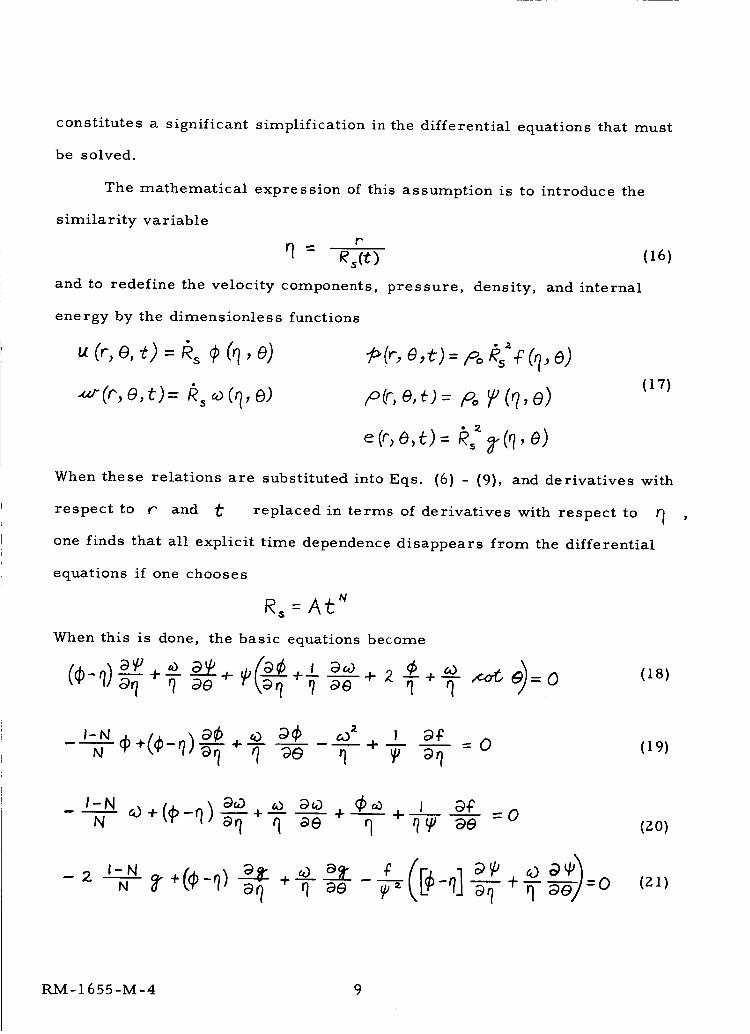
constitutes a significant simplification in the differential equations that must
be solved.
The mathematical expression of this assumption is to introduce the
similarity variable
r
and to redefine the velocity components,
energy by the dimensionless functions
.¢.v'(r,e,t)= #, _(q, e)
pressure, density,
(16)
and internal
_,(,,-,e,,_._=po,4'_"_q, e)
/o(,-e,_._= p__,(?, e)(17)
When these relations are substituted into Eqs. (6) - (9), and derivatives with
respect to r and t replaced in terms of derivatives with respect to
one finds that all explicit time dependence disappears from the differential
equations if one chooses
R, = Al_ _
When this is done, the basic equations become
_ = 0 (18)
-0 (19)
(zo)
(2,1)
RM-1655-M-4 9
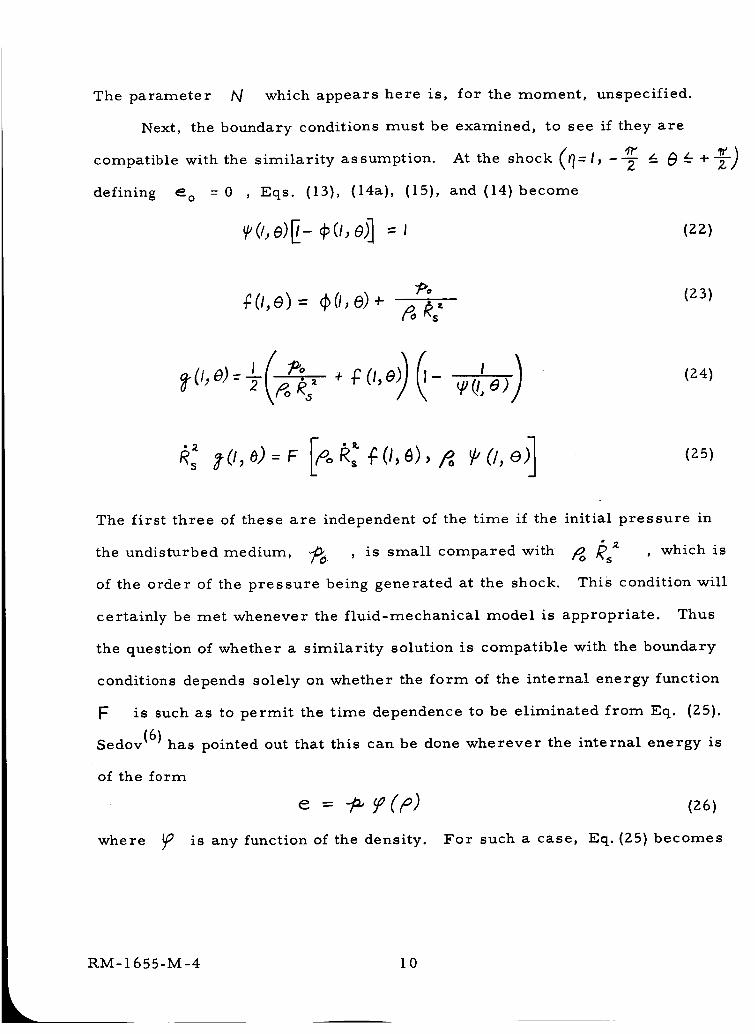
The parameter N which appears here is, for the moment, unspecified.
Next, the boundary conditions must be examined, to see if they are
compatible with the similarity assumption.
defining _o = 0 , Eqs. (13), (14a), (15),
At the shock =l_ --_-
and (14) become
(22)
_o (z3) O,e) = GO, e)+
(24)
(25)
The first three of these are independent of the time if the initial pressure in
the undisturbed medium, ._ , is small compared with _ _s _ , which is
of the order of the pressure being generated at the shock. This condition will
certainly be met whenever the fluid-mechanical model is appropriate. Thus
the question of whether a similarity solution is compatible with the boundary
conditions depends solely on whether the form of the internal energy function
F is such as to permit the time dependence to be eliminated from Eq. (25).
Sedov (6) has pointed out that this can be done wherever the internal energy is
of the form
e = f (z6)
where _ is any function of the density. For such a case, Eq.(25) becomes
RM-1655-M-4 10
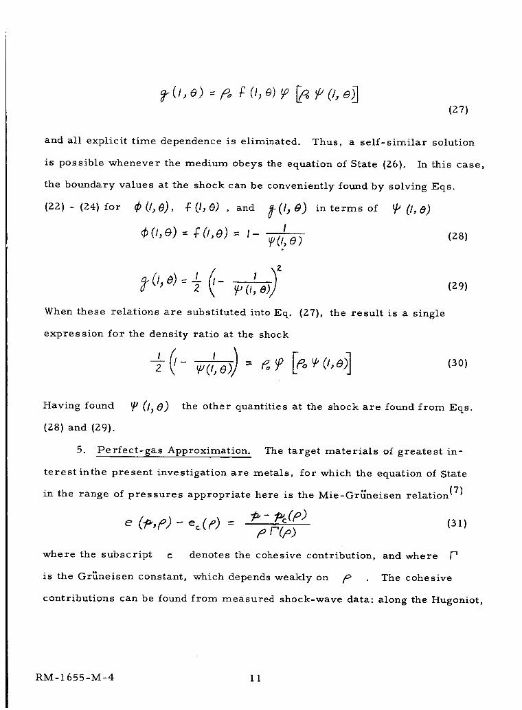
(27)
and all explicit time dependence is eliminated. Thus, a self-similar solution
is possible whenever the medium obeys the equation of State (26). In this case,
the boundary values at the shock can be conveniently found by solving Eqs.
(22) - (24) for _(i, 0), _-(I,_) , and _-(1,0) interms of _ (I,e)
I¢(/,e) = _(i,e) = t _(i,e) (z8)
(I,e) --7 e (_,e (zg)
When these relations are substituted into Eq. (27), the result is a single
expression for the density ratio at the shock
Having found _ (i)8) the other quantities at the shock are found from Eqs.
(28) and (29).
5. Perfect-gas Approximation. The target materials of greatest in-
terestinthe present investigation are metals, for which the equation of State
in the range of pressures appropriate here is the Mie-Gr_neisen relation (7)
e (-p,p) - e_CP) = _- _(F') (31)pr"(z)
where the subscript c denotes the cohesive contribution, and where
is the Gr_neisen constant, which depends weakly on /o The cohesive
contributions can be found from measured shock-wave data: along the Hugoniot,
RM-1655-M-4 11
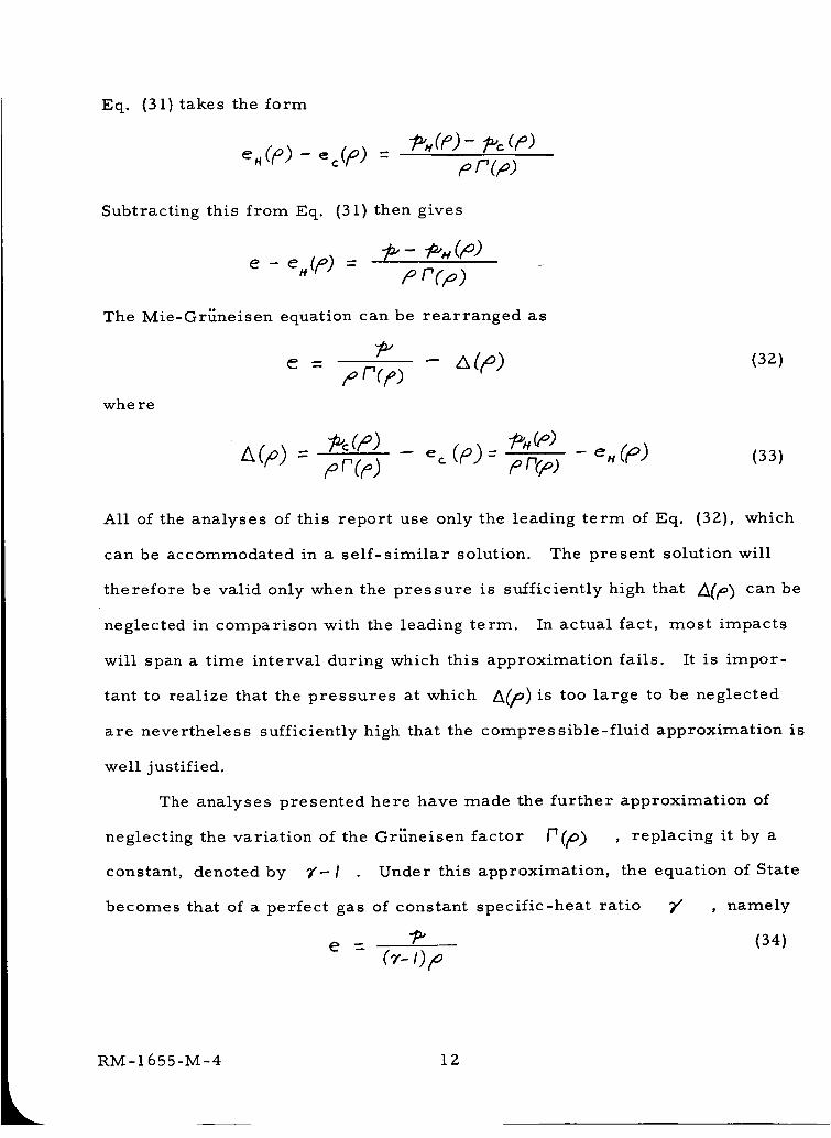
Eq. (31) takes the form
e. ('to,) - ec(/O )_(_)- _c (p)
pr(p)
Subtracting this from Eq. (31) then gives
e -- e_(/m) --p r(p)
The Mie-GrKneisen equation can be rearranged as
e - A(p) (3z)p n(r)
whe re
pc(r) _ m nrp) e " (R) (33)
All of the analyses of this report use only the leading term of Eq. (32), which
can be accommodated in a self-similar solution. The present solution will
therefore be valid only when the pressure is sufficiently high that _(R) can be
neglected in comparison with the leading term. In actual fact, most impacts
will span a time interval during which this approximation fails. It is impor-
tant to realize that the pressures at which A(p) is too large to be neglected
are nevertheless sufficiently high that the compressible-fluid approximation is
well justified.
The analyses presented here have made the further approximation of
neglecting the variation of the Gr{_neisen factor _(/9) , replacing it by a
constant, denoted by _'- I Under this approximation, the equation of State
becomes that of a perfect gas of constant specific-heat ratio ;r" , namely
"P" (34)
e - (__ 0p
RM-1655-M-4 12
The use of this state equation amounts to a high-pressure approximation of
the Mie-Gr{ineisen relation, with p (_)) taken as a constant, equal to /-]
and it makes available all the results of the extensive literature dealing with
blast waves in a perfect gas. Because /_(/o) is typically about 2.0 to 3. 0,
9/ will be on the order of 3.0 or greater. It should be borne in mind,
however, that the similarity solution is not limited to the predictions made
with the perfect-gas model; the variation of P could be accounted for, but
is neglected here as a matter of convenience.
When the perfect-gas approximation is made,
((19) or (ll)) becomes
at _r +--6- aO _r r
In terms of the similar functions, this is
the energy equation
/9# _'_ 9_) 0v,
(35)
(36)
It is interesting to examine the accuracy of the perfect-gas model for
a particular material. The equation of State enters the analysis by way of
Eq. (ll), which states that the entropy of a given particle does not change,
after being processed by the shock. In general, the entropy of a medium is
a function of any two thermodynamic variables, for example the pressure and
density. In making the ideal-gas approximation, the entropy is assumed to
depend on these only in the special combination
To assess the quantitative validity of this assumption, then, it is necessary to
determine how accurately the isentropic states of a given material are
RM-1655-M-4 l 3
approximated by the relation
,_,'_t_ -- 9/ _ _ = constant (37}
An explicit equation of state for iron, developed by a group at the Los Alamos
Scientific Laboratory, has been published by Bjork. (8} This equation has been
used to calculate the pressure as a function of internal energy at various den-
sities. The resulting map of thermodynamic states is shown in Fig. 1. Also
shown is the Hugoniot, i.e. , the locus of states which can exist behind normal
shock waves. This locus is the set of points which satisfy the condition
e - 2po
where Po is the normal density of iron, 7. 86 grams per cubic centimeter.
The experimental Hugoniot curve, recently determined up to pressures of nine
megabars by Altshuler et al (9) is included, and agrees quite well with the the-
oretical curve. In addition to this experimental check, the pressures shown on
Fig. 1 at zero energy agree quite well with the Mie-Gr_neisen values
given by Altshuler et al in an earlier publication. (I0} Thus Fig. I may be con-
sidereda valid representation of the thermodynamic states of compressed iron.
Three isentropes have been added to this map, by a trapezoidal-rule
integration of
e //po
It should be noted that Eq. {39} provides asimplewayofcalculating the relativecontributions from the two terms in Eq. (32}
RM-1655-M-4 14
which holds for constant entropy. The three isentropes shown may be
thought of as describing the histories of three particles which lie along
the axis of symmetry in a given impact, and which are therefore processed
by successively weaker stages of the same shock wave. Particle 1, for
example, is raised from its normal state to the point shown on the Hugoniot
by a shock wave moving at 2-0.8 km/sec; its subsequent expansion to low
density takes place along the isentrope shown. In similar fashion, par-
ticles 2 and 3 are processed by the shock when it is traveling at 16. 5 and
8.62 km/sec, respectively. The _:_ , p-coordinates of these three isen-
tropes are re-plotted in Fig. 2. Large portions of these curves are accurately
reproduced by a constant value of 7' , i.e._ they have a constant slope.
6. Procedure for finding _ . In applying a constant - _" theory to
any given impact problem, only a single value of 7" may be used. If, in
the example cited above, one chooses the value appropriate to particle 1 at
the shock, the approximation will begin to deteriorate for the lower-density
states of this particle, and will be less accurate for all states of particles
2 and 3. In order to minimize the error, it would appear that 7" should
match the higher-density, higher-pressure portions of the flow. Partly for
this reason, and partly for ease of application, the procedure recommended
here is to choose 7" so as to match conditions at the impact point. For
any impact, one may imagine that there is a small region in the immediate
vicinity of the impact point, where the collision is equivalent to the planar
impact of two semi-infinite bodies.
RM-1655-M-4 15
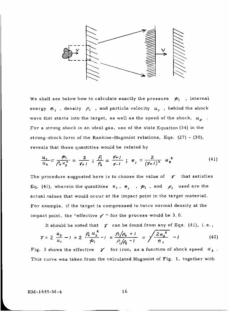
We shall see below how to calculate exactly the pressure _/ , internal
energy _/ , density /91 , and particle velocity /41 , behind the shock
wave that starts into the target, as well as the speed of the shock, _$
For a strong shock in an ideal gas, use of the state Equation(34) in the
strong-shock form of the Rankine-Hugoniot relations, Eqs. (27) - (30),
reveals that these quantities would be related by
The procedure suggested here is to choose the value of _" that satisfies
Eq. (41), wherein the quantities _i , _l , 7_i , and P# used are the
actual values that would occur at the impact point in the target material.
For example, if the target is compressed to twice normal density at the
impact point, the "effective _ " for the process would be 3. 0.
It should be noted that
"7"= 2. _--I = 2 /
Fig. 3 shows the effective Z"
This curve was taken from the calculated Hugoniot of Fig.
(41)
can be found from any of Eqs. (41), i.e.,
- _/_ -I - / _7 t (42)
for iron, as a function of shock speed b_$
1, together with
RM=I 655=M-4 16
the experimental data of Altshuler et al (9) and of Walsh et al. (11) Typically
of most materials, the effective 7" is on the ordei of 10 to 20 for weak
shock waves, and is more like 2 to 3 for strong shock waves.
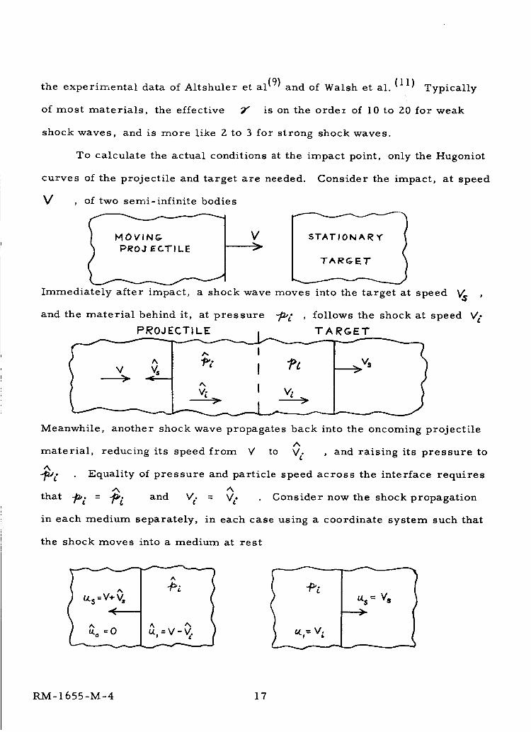
To calculate the actual conditions at the impact point, only the Hugoniot
curves of the projectile and target are needed.
V , of two semi-infinite bodies
Consider the impact, at speed
Vf
Immediately after impact, a shock wave moves into the target at speed V_
and the material behind it, at pressure 7mr , follows the shock at speed v,.
Meanwhile, another shock wave propagates back into the oncoming projectile
A
material, reducing its speed from V to V t. , and raising its pressure to
J_t' Equality of pressure and particle speed across the interface requires
that _ = _ and V_. = V t Consider now the shock propagation
in each medium separately, in each case using a coordinate system such that
the shock moves into a medium at rest
A
Au.o = V- V.
RM-1655-M-4 17
The problem is to choose, for a given impact speed V , a pair of values
A
V's and V s such that _>o = _. and Ve. = _. Olshaker and
Bjork (12) have described a convenient graphical method of solution. For
the present purpose, where the solution is required over a range of impact
speeds, it is much simpler to turn the problem around, choosing the pressure
at the interface, and asking what impact speed this corresponds to. The
Ik
choice of _d (which equals #d ) determines the particle velocities _t
and _l , from the Hugoniot curves for the two materials. The impact
speed is then determined by the equality of particle speeds in the laboratory
frame of reference, namely
A ,%
V. = u'l =V. = V-a_( e
or" V = _l + _l
(43)
The value of 9/ can then be found from any of Eqs. (42). This process
is illustrated in Fig. 4; here are shown the "_I ' 641 Hugoniot data for
iron and lead, taken from Altshuler et al. (9) Choosing an interface pressure
of 8 megabars gives _t = 6.6 km/sec and 7. 0 km/sec in lead and iron, re-
spectively. Thus the impact speed required to generate these conditions must
have been 13. 6 km/sec. If lead is the target, the effective / is determined
as follows:
a) The shock speed is determined, either from a graph of _/ vs. U s ,
or _>l vs. _S , or else from Eq. (14a)
&_$ =_ = I0.69 km/secPo _ ,
b) 7" is then found from Eqs. (4)
2us?'- I =2.24
Repeating this process at a succession of values of _t_I determines y'(V) ,
RM-I 655-M-4 1 8

as shown in Fig. 5.
The determination of
velocity and particle velocity are linearly related
(As = C 4-sun (44)
The measured Hugoniots for many materials are well approximated by this
relation, at least up to pressures around two megabars.
7" (V) takes on a simple form when the shock
Using Eq.of c and S for a number of materials.
Table I lists values
(14a), the particle
(45)
velocity corresponding to a given pressure is
The impact speed can then be found by applying this formula to the projectile
and target materials, and _" is found in the usual way, for example from
2 (C + S U,) (46)X'= -IU.I
The linear relation between shock velocity and particle velocity ceases to be
valid at extremely high pressures, but our present experience indicates that
it is a satisfactory extrapolation method for impact speeds up to 50 km/sec.
The Gr{ineisen constant, _ , may be as large as 3.0 for the materials of
interest here. Thus, as long as 7' is less than 4.0, the perfect-gas approx-
imation may be interpreted in the sense indicated above, namely that the
leading term of the Mie-Gr_neisen equation dominates, and the choice of
is essentially an approximation to the Gr{lneisen factor. If the "effective
2' " is greater than 4, however, no such interpretation can be made, and the
use of a perfect gas must be viewed as an attempt to match the entire Mie-
Gr[{neisen equation with a single term. Obviously, the approximation will
not be as good in this regime, and the theoretical predictions at low impact
RM-1655-M-4 19
speed (i. e., high 7' ) must be considered less reliable on this account. An
estimate of the impact conditions for which _z is less than 4. 0 can easily
be derived from the relations above, from which it can be shown that 7" will
be less than 4.0 whenever the impact pressure is greater than
(5- _ 5)=
As S ranges from 1 to 1. 5, this pressure varies from d to _ _c
Thus, the present theory may be expected to agree with experiment at lower
Z
velocities, the lower the value of _oC Reference to Table I, for example,
shows that, at a given velocity, impacts into lead would be better described
than those into, say, copper. We shall see below that this is indeed the case.
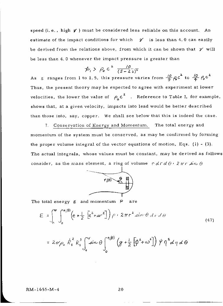
7. Conservation of Energy and Momentum. The total energy and
momentum of the system must be conserved, as may be confirmed by forming
the proper volume integral of the vector equations of motion, Eqs. (i) - (3).
The actual integrals, whose values must be constant, may be derived as follows
consider,
The total energy
as the mass element, a ring of volume
_: and momentum P are
,," J.rdO, 2 _'r ._g_u(3
E(47)
iio (±
2O
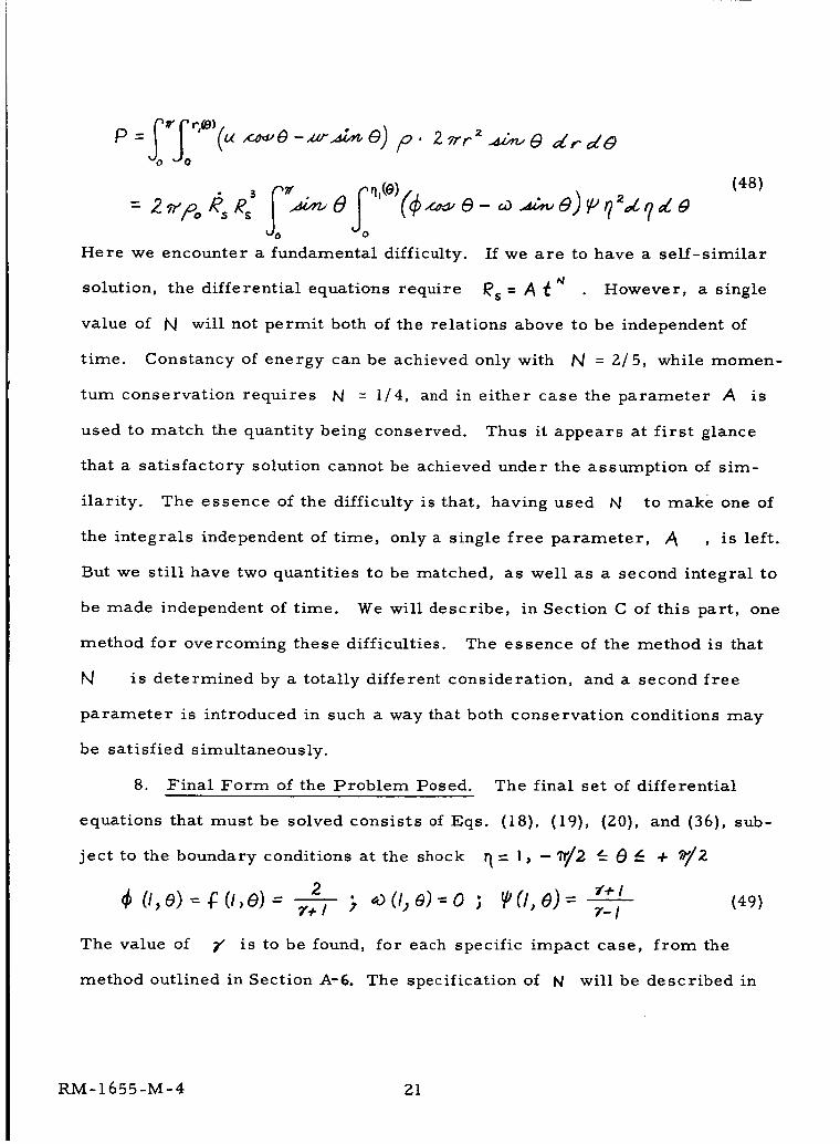
(48)
Here we encounter a fundamental difficulty. If we are to have a self-similar
solution, the differential equations require _s = A (N However, a single
value of N will not permit both of the relations above to be independent of
time. Constancy of energy can be achieved only with N = 2/5, while momen-
tum conservation requires _ = I/4, and in either case the parameter A is
used to match the quantity being conserved. Thus it appears at first glance
that a satisfactory solution cannot be achieved under the assumption of sim-
ilarity. The essence of the difficulty is that, having used /_ to make one of
the integrals independent of time, only a single free parameter, _ , is left.
But we still have two quantities to be matched, as well as a second integral to
be made independent of time. We will describe, in Section C of this part, one
method for overcoming these difficulties. The essence of the method is that
is determined by a totally different consideration, and a second free
parameter is introduced in such a way that both conservation conditions may
be satisfied simultaneously.
8. Final Form of the Problem Posed.
equations that must be solved consists of Eqs.
ject to the boundary conditions at the shock
The final set of differential
(18), (19), (20), and (36), sub-
+2
¢ CI,e) = # (i, e) = >
The value of _" is to be found,
method outlined in Section A-6.
_)(#) 0)'=-0 ; _('], _))- _'+1 (49)Z-I
for each specific impact case, from the
The specification of N will be described in
RM-1655-M-4 21
detail below.
As a final note on the mathematical nature of the problem, it should
be pointed out that two pairs of characteristics of Eqs. (18), (19), (20), and
(36) can be found by standard methods. One pair corresponds to the particle
paths of the original unsteady flow, while the other pair, related to the Mach
lines of the original flow, reveals that the equations have elliptic or hyperbolic
character, according to whether
- +ca _ < 0(50)
The line in the _ D plane along which this quantity vanishes is referred to
below as the "sonic" line, because of its relation to the Mach lines of the
original flow.
22
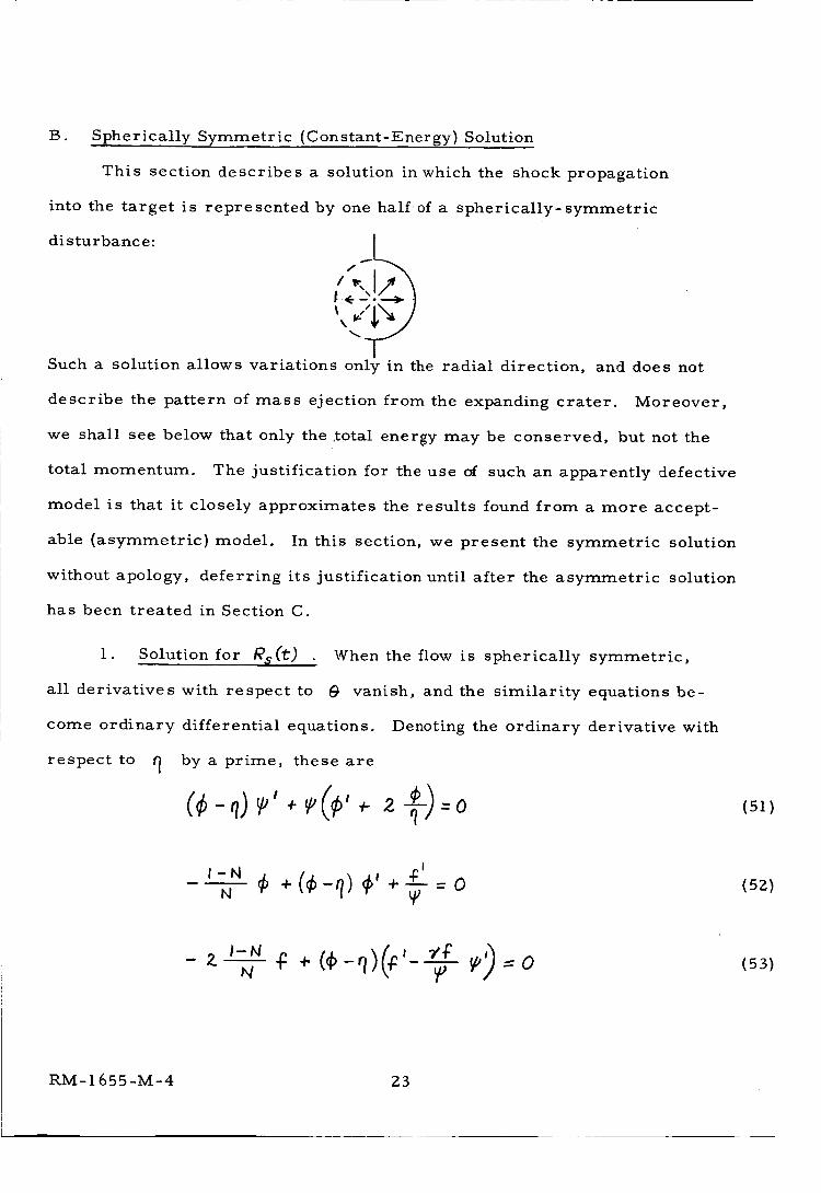
B. Spherically Symmetric (Constant-Energy) Solution
This section describes a solution in which the shock propagation
into the target is represented by one half of a spherically-symmetric
disturbance: Iz_'_-I__
r _--'!& t
Such a solution allows variations only in the radial direction, and does not
describe the pattern of mass ejection from the expanding crater. Moreover,
we shall see below that only the .total energy may be conserved, but not the
total momentum. The justification for the use of such an apparently defective
model is that it closely approximates the results found from a more accept-
able (asymmetric) model. In this section, we present the symmetric solution
without apoIogy, deferring its justification until after the asymmetric solution
has been treated in Section C.
1. Solution for R_(t)
all derivatives with respect to
come ordinary differential equations.
respect to q by a prime, these are
When the flow is spherically symmetric,
@ vanish, and the similarity equations be-
Denoting the ordinary derivative with
I-N _ ¢,N ¢+(¢ q}
-2.--
(51)
(5Z)
(53)
RM-1655-M-4 23
These may be solved explicitly for the derivatives _l , _i , and _Pin
the form
I
I
w
_; _ _-N ¢
,-N 2v+]N fl N
)z 7"-£
The boundary conditions at the shock are
2 r+ /
Equations (54) - (56) (with N = Z/5) were first presented by G. I. Taylor,(l 3)
who worked out a few numerical and approximate analytic solutions, for
ranging from l.Z to 1.67, the range appropriate for gases. Subsequently,
an analytic solution of these equations (also with t4 = 2/5) was published by
(i 5) (1 6)J. L. Taylor,(14)Latter, and Sakurai. Simultaneously with Taylor's
work, SedoJ6)had also found this analytic solution. He worked in a different
coordinate system, where
'_ =___._ = Nz 7'_'
In these coordinates, the basic equations may be combined to yield a single
differential equation involving only ? and _ (see Appendix A for details of
the derivation):
(54)
(55)
(56)
(57)
(58)
RM- 1655-M-4 24
_'P_ -7
Having
integrating
as a function of, the quantities q and _ are found by
!
(c-N) q d_ ,_¢,_q - q dq 3 ¢
The boundary conditions at the shock are
The parameter b_ must be specifiecl, before solutions of these
equations can be found. It appears that physically acceptable solutions of
these equations exist only when b_ = 2/5, a value which conserves the total
energy, according to SectionA-7 above. When N is taken to be different
from 2/5, the solution exhibits infinite slopes. In fact, by working in the
, _ coordinates, the solution can be shown to become double-valued.
Figure 6 shows results typical of those found in the range0.25 __N -_ 0.4
when a solution of this sort is attempted. This nonexistence of symmetric
solutions apparently explains the difficulty encountered by Davids, Huang,
17.and Juanzemis in attempting to find a spherically-symmetric solution for
constant momentum ( N = 1/4).
In what follows, b_ is chosen as 2/5, and the terms "constant-energy"
and "spherically-symmetric" are used interchangeably in referring to the
solution.
(59)
(60)
(61)
(62)
RM-1655-M-4 25
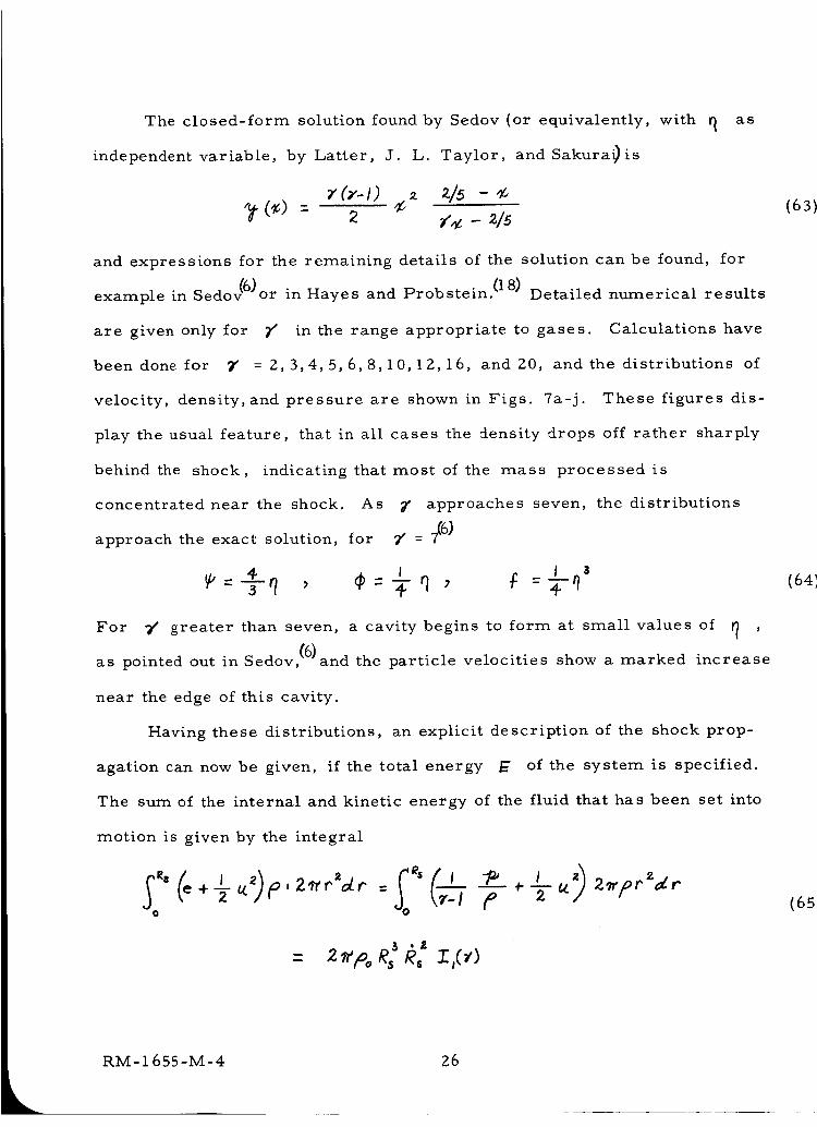
The closed-form solution found by Sedov (or equivalently, with
independent variable, by Latter, J.
(T-I)
L. Taylor, and Sakura_is
- 215
[_ as
and expressions for the remaining details of the solution can be found, for
example in Sedov_6)or in Hayes and Probstein. (18) Detailed numerical results
are given only for 7s in the range appropriate to gases. Calculations have
been done for 7 = 2,3,4,5,6,8,10,12,16, and 20, and the distributions of
velocity, density, and pressure are shown in Figs. 7a-j. These figures dis-
play the usual feature, that in all cases the density drops off rather sharply
behind the shock, indicating that most of the mass processed is
concentrated near the shock. As 7 approaches seven, the distributions
approach the exact solution, for 7' = _6)
_= _ l I 3
For 7' greater than seven, a cavity begins to form at small values of _ ,
as pointed out inSedov, {6)'and the particle velocities show a marked increase
near the edge of this cavity.
Having these distributions, an explicit description of the shock prop-
agation can now be given, if the total energy E of the system is specified.
The sum of the internal and kinetic energy of the fluid that has been set into
motion is given by the integral
o
(63)
(641
RM-I 655-M-4 26
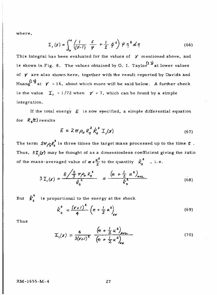
where,
is shown in Fig.
I',(_')= I) T _ _ #_z_q (66)
This integral has been evaluated for the values of 7' mentioned above, and
8. The values obtained by G. I. Taylor( 1 _at lower values
of _ are also shown here, together with the result reported by Davids and
Huan_l--9) at 7" = 16, about which more will be said below. A further check
is the value :r I = 1/72 when 7" = 7, which can be found by a simple
integration.
If the total energy E is now specified, a simple differential equation
for lids(t) results
(67)
The term 2f_g: is three times the target mass processed up to the time t •
Thus, 3Il(;' ) may be thought of as a dimensionless coefficient giving the ratio
of the mass-averaged value of e+_ to the quantity /_s , i.e.
E _p,,,%3 (_ .--/. u3 I,(7) =
6sz - _: (68)
Thus
is proportional to the energy at the shock
. ).= e ÷ I a,.* (69)gs 4 )-
4 (e+ _ _t z)Av_
I _)sMx'O') - 30"+0" (e + -_(70)
RM-1655-M-4 27
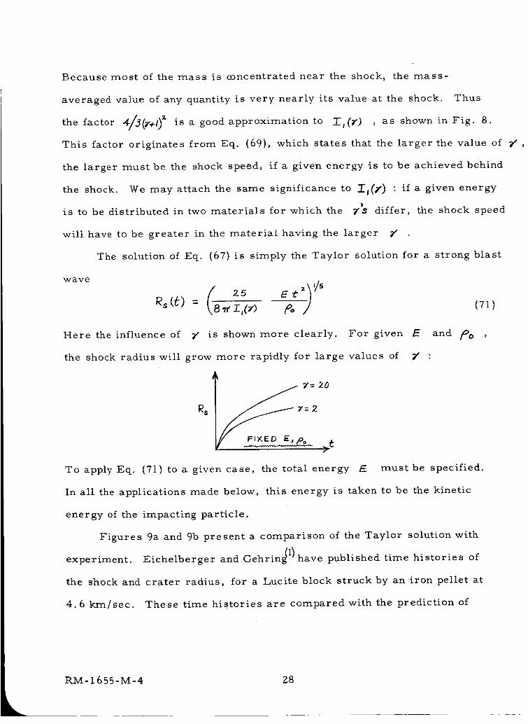
Because most of the mass is concentrated near the shock, the mass-
averaged value of any quantity is very nearly its value at the shock. Thus
the factor 4/3(_'÷I) z is a good approximation to Zl(_ ) , as shown in Fig. 8.
This factor originates from Eq. (69}, which states that the larger the value of
the larger must be the shock speed, if a given energy is to be achieved behind
the shock. We may attach the same significance to 10(_" ) : if a given energy
is to be distributed in two materials for which the _'S differ, the shock speed
will have to be greater in the material having the larger
The solution of Eq.
wave
(67) is simply the Taylor solution for a strong blast
'/5
Here the influence of _ is shown more clearly. For given E and _:_o ,
the shock radius will grow more rapidly for large values of F' :
Y= 20
f
To apply Eq. (71) to a given case, the total energy E must be specified.
In alI the applications made below, this energy is taken to be the kinetic
energy of the impacting particle.
Figures 9a and 9b present a comparison of the Taylor solution with
experiment. Eichelberger and Gehrin_ 1) have published time histories of
the shock and crater radius, for a Lucite block struck by an iron pellet at
4.6 krn/sec. These time histories are compared with the prediction of
RM-I 655-M-4 Z8
k
Eq. (71) in Fig. 9a. The agreement is reasonable, although the measured
rate of advance of the shock is faster than that of the constant-energy solution,
corresponding to a value of N around 0.67. It is important, in this connec-
tion, to recall that any constant-energy, self-similar solution will have
b_ = 0.4. Changing the value of 9/ will change only the amplitude. In
addition, any equation of state that permits a similarity solution will also
leave b_ unchanged in a constant-energy solution. Furthermore, in a solu-
tion which conserves both energy and momentum, the evidence advanced in
Section C below suggests that, if anything, hJ will be less than 0.4. On the
other hand, it is true in general that the shock speed will decelerate from
the blast-wave behavior (_5 _tz/$)at early time to the acoustic limit t)
at late time. The data of Fig. 9a apparently lie in a transitional regime
between these two limits. Thus it appears that the only way to achieve a
better comparison with the data of Fig. 9a is to include the nonsimilar effect,
associated with the term A_) in the equation of state. The present report
does not treat this effect, but it is encouraging to note how well the blast-
wave theory does in spite of this deficiency. Moreover, the blast-wave
theory can be expected to improve at higher impact speeds.
Figure 9b presents a different type of experimental check on the blast-
wave theory. Here we show the wave speed versus shock position, measured
in a very ingenious series of experiments by Frasier and Karpov. (2) The data
pertain to a wax target, struck by an Ethocell pellet at 4 km/sec, and
apparently lie in a range where the shock strength is too low to justify the
strong-shock assumptions. However, the data do not appear to be incon-
sistent with a transition from a high shock speed down to the stress-wave
RM-1655-M-4 29
velocity.
velocity,
range.
The constant-energy solution is not extrapolated beyond this
since the blast-wave approximation is clearly inadequate in that
In general, then, the blast-wave solution may be considered a rea-
sonable approximation to this very limited amount of experiment, and, if
used with caution, may be expected to serve as a suitable basis for crater
prediction.
Z. Crater formation criterion. The blast-wave solution given in
Eq. (71) may be considered a valid description of the shock propagation in
the target so long as the pressures being generated are large enough to
justify an inviscid-fluid model_ These pressures decay rapidly, however,
and to provide a valid solution at later time, a transition is needed from the
blast-wave model to one which properly describes the plastic flow, and
ultimately the elastic response of the target. Such a solution would predict
the configuration in which the target material finally comes to rest, and
the definition of the final crater dimensions v_uld be unequivocal. A solu-
tion of this sort is not presently available, however. In its absence, the
best that can be done is to identify the point at which the transition from
blast-wave theory ought to occur, and to make an estimate, based on con-
ditions at that instant, of what the final crater dimensions will be.
The method for predicting crater size that is adopted in the present
report is that the shock radius at the instant at which the blast-wave solution
is to be cut off is the radius of the crater that will ultimately develop. The
use of such a procedure is equivalent to the statement that all of the material
processed by the high-pressure phases of the shock wave will ultimately be
30
ejected from the target.
The cutoff point must be the point at which the shock-wave intensity
has decayed to some preassigned level. If we require that the pressure
behind the shock shall have fallen to the level _ (to be identified below
with the material strength), then, since the pressure behind the shock is
given in general by
_'_- _+1 _
we would identify the crater radius as the value of
2If the solution for the shock radius is written as
_825 E _1'/5e,-At , A=
(72)
_s at the instant when
(73)
then the time can be replaced in favor of the shock radius, according to
The shock speed is therefore
= 3-A k_--J
Equating this to Eq. (73), and replacing
have
or
(74)
(75)
(76)
_'s by the crater radius _c , we
P(77)
RM-1655-M-4 31
Taking
and diameter _ then gives
__a_ 2
This solution is shown in Fig.
projectile-target combination,
to be the kinetic energy of a spherical projectile of density pp
I, Iv) JP(78)
i0 for various values of ;_ For a given
7' is large at low impact speeds, and de-
creases as _/ increases. Thus the crater radius is predicted to grow with
a power of _/ somewhat less than 2/3. In most cases, the power is approx-
imately 1/3. The influence of _ displayed in Fig. 10 is the same as that
mentioned earlier: at a given kinetic energy, the higher values of _ produce
faster shock waves, which will penetrate more deeply before they decay to the
prescribed pressure _D Stated another way: if a given energy is to be
added to the target by a shock wave across which the energy change per unit
shock speed is relatively small, then the shock speed itself must be relatively
large. We will return to a discussion of this point below.
The value of _P must be chosen, in order to predict actual crater
dimenions. It was pointed out above that the inviscid-fluid approximations
are valid only so long as the pressures being generated at the shock are
large compared with the target's resistance to shear deformation. Thus,
the pressure at which the blast-wave solution is to be cut off must be a
measure of the shear strength of the material. Part II, below, points out
that the proper value to use for this property is the intrinsic shear strength,
which lies between the limits G/30 and C_/_, C__ being the dynamic shear
modulus, as measured, for example, by ultrasonic techniques. Using
these values for the intrinsic shear strength, the predictions of Eq. (71)
RM-1655-M-4 32
i
are compared with experiment in Figs. 11-13. In preparing the theoreti-
cal curve for iron striking lead (Fig. ll), the variation of 7" and V
was taken from Fig. 5, and the material properties used were found from
Table 4- The lower strength leads to a deeper crater prediction, since
the shock wave must penetrate more deeply in decaying to a lower pressure.
The experimental data, taken from the compilation by Herrmann and Jones (g0)
are seen to agree quite wellwith the higher-strength prediction. Figure IZ
gives results for iron striking iron. In addition to low-speed experimental
data, this figure also shows Bjork's machine solution. Again the agreement
is reasonable. Figure 13 shows the results found for aluminum striking
copper. Here the agreement with experiment is somewhat poorer. The
Hugoniot data for iron, lead, and copper were taken from Altshuler et al,(9)
while for aluminum the low-pressure data of Walsh et al(I_ were used, together
with the high-pressure estimate made by Lake and Todd. _21)
On the basis of this evidence, it would appear that the best agreement
with experiment is achieved by using the value C_/2fr for the intrinsic shear
strength. Part If, below, presents a discussion of why such a conclusion
might be expected.
The approximations on which this theory is based will improve at
higher impact speeds. Thus it is not surprising to find such good agreement
for the case of lead targets, in which hypervelocity conditions are achieved
at relatively low speed. The fact that the slope of these data and of Bjork's
results are well matched lends substance to the belief that crater radius will
grow somewhat more slowly with impact speed in the very high-speed range,
compared with its growth rate at lower speed.
RM- 1655-M-4 33
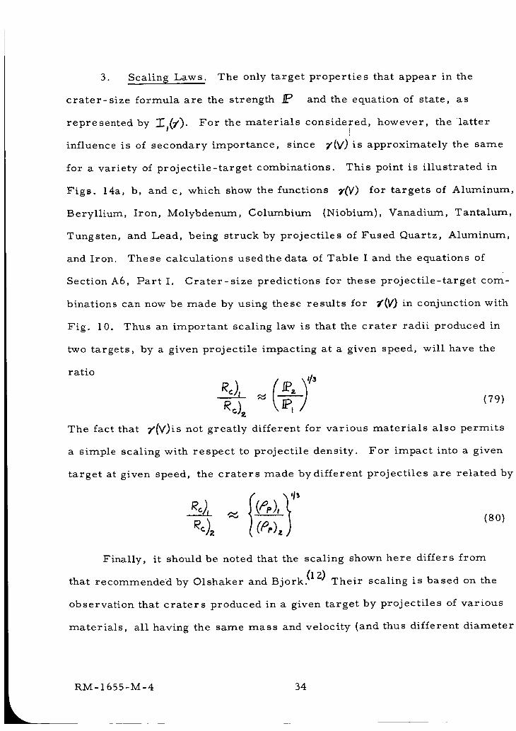
3. Scaling Laws. The only target properties that appear in the
crater-size formula are the strength _ and the equation of state, as
represented by ][a(7'). For the materials considered, however, the latter
influence is of secondary importance, since Y(V) is approximately the same
for a variety of projectile-target combinations. This point is illustrated in
Figs. 14a, b, and c, which show the functions _'_V) for targets of Aluminum,
Beryllium, Iron, Molybdenum, Columbium (Niobium), Vanadium, Tantalum,
Tungsten, and Lead, being struck by projectiles of Fused Quartz, Aluminum,
and Iron. These calculations used the data of Table I and the equations of
SectionA6, Part I. Crater-size predictions for these projectile-target com-
binations can now be made by using these results for _'(V) in conjunction with
Fig. i0. Thus an important scaling law is that the crater radii produced in
two targets, by a given projectile impacting at a given speed, will have the
ratio
(79)
The fact that _'(V)is not greatly different for various materials also permits
a simple scaling with respect to projectile density. For impact into a given
target at given speed, the craters made by different projectiles are related by
N =
Finally, it should be noted that the scaling shown here differs from
that recommended by Olshaker and Bjork. (IZ) Their scaling is based on the
observation that craters produced in a given target by projectiles of various
materials, all having the same mass and velocity (and thus different diameter
RM-1655-M-4 34
k
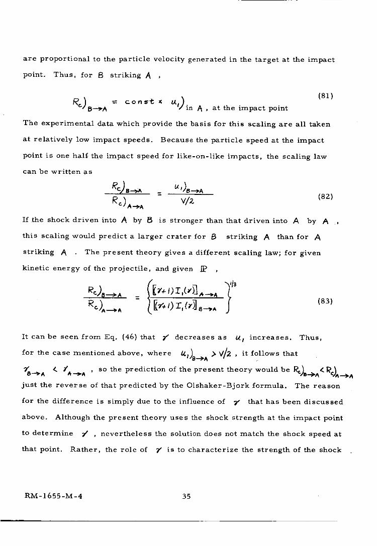
are proportional to the particle velocity generated in the target at the impact
point. Thus, for 8 striking A ,
(81)Re) = const _ Ix,)
B--_A in A , at the impact point
The experimental data which provide the basis for this scaling are all taken
at relatively low impact speeds. Because the particle speed at the impact
point is one half the impact speed for like-on-like impacts, the scaling law
can be written as
_C) B.__A = bli )8.__ A
vlz
If .the shock driven into /_ by B
(82)
is stronger than that driven into A by A
this scaling would predict a larger crater for B striking _ than for
striking A The present theory gives a different scaling law; for given
kinetic energy of the projectile, and given _ ,
: t I'r,(,>-] (83)
It can be seen from Eq. (46) that _r" decreases as b_ I increases. Thus,
for the case mentioned above, where _')B'-">A > V/2 , it follows, that
___^ < /____^ , SO the prediction of the present theory would be P,c)__._< I_c)^.___._
just the reverse of that predicted by the Olshaker-Bjork formula. The reason
for the difference is simply due to the influence of 7" that has been discussed
above. Although the present theory uses the shock strength at the impact point
to determine 7' , nevertheless the solution does not match the shock speed at
that point. Rather, the role of 7" is to characterize the strength of the shock
RM- 1655-M-4 35
throughout its entire subsequent history. The stronger the shock, the
less rapidly it must travel, on the average, in order to transfer a given
energy to the target.
Unfortunately, the data required to resolve this difference are not
presently available. In actual fact, of course, the speed of the shock as
it advances into the target will remain close to the one-dimensional, impact-
point value until the time when the projectile has been destroyed. Thereafter,
its speed will be governed by the requirement that the total energy and momen-
tum be conserved. One must certainly expect that the Olshaker-Bjork type
of scaling will be correct when the entire cratering process is controlled by
conditions during the time when the projectile is being destroyed. This
condition has been shown to exist at low impact speed. Whether it will con-
tinue to hold at higher impact speeds is presently open to question. On the
other hand, the blast-wave theory in its present form is valid only at impact
speeds such that the collision time is a small fraction of the time required
for the crater to form, and so its predictions are relatively insensitive to the
details of the impact process. The fact that it leads to a scaling law differ-
ent from that observed at low speed is therefore not surprising, but must
be regarded as tentative, pending the availability of a less approximate
theory, and of definitive experiments.
It would appear that these qualitative conclusions would remain un-
changed even if more realistic Gr[{neisen coefficients were employed in a
blast-wave solution. The extent by which they might be modified by the re-
sults of a non-similar solution will form an interesting area for further
research.
RM-1655-M-4 36
4. Comparison with Other Theories. It is of interest to compare
the present analysis w;th a similar theory given by Davids et al. (17)'09
These authors also use a spherically symmetric model, and represent the
equation of state by a gas of constant _" , which they determine by fitting
the Hugoniot (not the isentropes) by an equation of the form 9_ _' They
work out a numerical solution for 7" = 16, and h/ = 2/5, but apparently
do not take advantage of the closed-form solution. The value which they
find numerically for the cavity radius differs slightly from that given by
the exact result, and this small discrepancy may explain why their value
of T,(_¢), plotted in Fig. 8, is somewhat below the present results• As noted
earlier, they have also attempted a solution for constant momentum ( h/ = 1/4).
The principal difference between their theQry and the one described here lies
in the criterion used for crater formation. Like Bjork, these authors do not
incorporate the material strength. Rather,they define the crater as the cavity
radius at the point where a certain graph of shock radius versus time is judged
to have reached an essentially constant value. They infer from this that
crater radius will vary as the 2/5 power of the impact speed.
The present formula for crater size is very similar to that derived
empirically by Eichelberger and Gehring.(1) Their result states that the crater
volume varies directly with the kinetic energy of the projectile, and inversely
with the Brinell hardness of the target,
2 _ -g E
where E and _c are taken in c.xj5 units, and B in the customary units of
kilograms force per square millimeter. The present result is
RM- 1655-M-4 37
2 _ 2 E
which differs from Eichelberger and Gehring's formula by the influence
of _" , and by the use of C,/;Z_. There appears to be no simple relation
between the dynamic shear modulus and the Brinell hardness, so that no
general comparison can be made. For the case of copper, G/2._is about
ten times the Brinell hardness, and the two crater-size predictions are equal
at Z = 4.6, a representative value. In general, both predictions yield the
same order of magnitude, and differ principally in that the present one in-
dicates a lower growth rate of crater size with impact speed.
RM-1655-M-4 38
.%,
C. Asymmetric Solutions "_
In this section we present a blast-wave solution which explicitly des-
cribes the pattern of mass ejection from the target. Because of the lack of
spherical symmetry, two independent variables enter, and the solution of
the problem is considerably more difficult to find. Certain approximations
are resorted to, in order to obtain partial solutions. From these, a very
important result is found, namely that this more difficult, but more physically
realistic solution is for practical purposes the same as the vastly-simpler
constant-energy solution described above.
In addition, this section returns to the question of the simultaneous
conservation of energy and momentum, and describes one method by which
this can be achieved. The method is illustrated by applying it to the case of
a one-dimensional impact, such as might occur when a thin disk strikes a
target.
The first six of the subsections below describe the axisymmetric case,
while the last three present the one-dimensional solution.
1. Two-Dimensional Solution. The model which allows for spatial
variations in two directions behind a hemispherical shock wave was intro-
duced in Section A, above. The similarity equations, Eqs. (18) - (20), and
Eq. (36), are partial differential equations, containing both q and
The term "asymmetric" as used here refers to symmetry with respect to
the target surface, while the term "axisymmetric" refers to symmetry aboutthe axis along which the projectile impacts. All of the solutions of this
report are taken to be axisymmetri9, but may be either symmetric or asym-metric with respect to the target surface.
RM- 1655-M-4 39
as independent variables. They are of mixed cha r acte r , containing both
elliptic and hyperbolic regions , and, furthermore, they must meet a zero
pressure boundary cond i tion a l ong a line who s e lo c ation is unknown in
advance. To make matters worse, the differential equ a t i ons contain a para
meter N whose value is unspecified. No attempt h as b een m ade to solve
the se equations. Instead, partial solutions are sou ght b y re stricting
attention to conditions along the axis of symmet r y. In thi s w ay , we can
learn a great deal about the s olution, with relative l y littl e e ffort. The
most important item uncovered is the criterion fo r choo s ing N for each
7' ' N must be chosen so as to permit a smooth t ransition f rom the el
liptic to the hyperbolic region .
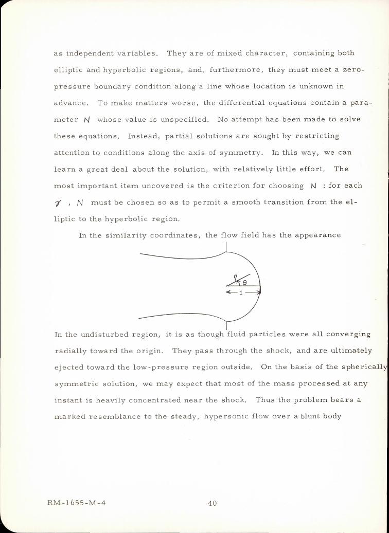
In the similarity coordinates, the flow fie l d ha s the ap p e arance
In the undisturbed region, it is as though fluid particle s were a ll c onverging
radially toward the origin. They pass through the shock, and a re ult imately
ejected toward the low-pressure region outside. O n the ba s is of the sphericall
symmetric solution , we may expect that most of the mas s p r oc essed at any
instant is heavily concentrated near the shock. Thus the p rob l e m bears a
marked resemblance to the steady, hypersonic fl ow over a b lun t body
RM-1655-M-4 40
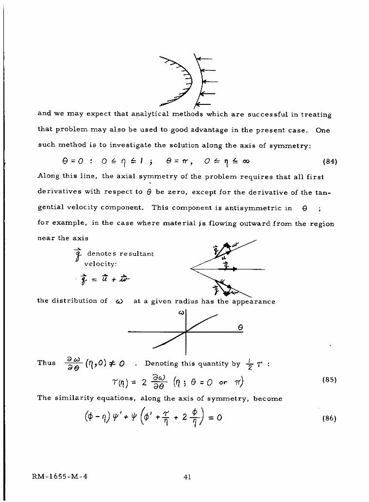
and we may expect that analytical methods which are successful in treating
that problem may also be used to good advantage in the present case. One
such method is to investigate the solution along the axis of symmetry:
@=0 : 0 L_ _ _-- I _ O= fr', 0 _- rl z-- oo (84)
Along this line, the axial symmetry of the problem requires that all first
derivatives with respect to (9 be zero, except for the derivative of the tan-
gential velocity component. This component is antisymmetric in @ ;
for example, in the case where material _s flowing outward from the region
near the axis
L denotes resultant
velocity:
--_ tA +_
the distribution of GO at a given radius has the appearance
e
IThus aoO (q,O) _: 0 Denoting this quantity by -_ _ :
The similarity equations, along the axis of symmetry, become
+-E * 2 =0
(85)
(86)
RM-1655-M-4 41

_ _, =O (88)
where primes indicate ordinary differentiation with respect to _ These
equations are referred to in what follows as the "centerline" equations.
Except for the presence of _' in (86), these are identical with the Taylor
equations for a spherically-symmetric disturbance, discussed in Section B.
The function T'(q) represents the influence of off-axis conditions, as must
be expected whenever a partial differential equation is specialized to a single
line in the plane of its independent variables.
Equations (86) - (88) may be solved explicitly for the derivatives in the
form
12,_ -_I 2 (I-N) _ I-N_=
)2 r_ }(¢-'I){{*- q _,(89)
T1 4:(___I_ ,'_:
(90)
(91)
The boundary conditions at the shock are
2 _'+l _(0 0¢>0)= -;0)= r+l "; _(I)-- _'-/ ; ' =
These equations contain two unspecified quantities, b4 and _' {'1_)
(92)
The
_ RM_655-M-4
42
next two subsections discuss the determination of these.
2. Criterion for Choosing N The centerline equations obviously
have a singularity at the point where the denominator (___)z 7"_2 vanishes.
This quantity is the special case, for _o = 0, of the function discussed in
Section A'8, whose sign determines whether the partial differential equations
have elliptic or hyperbolic character. Thus the point on the axis of symmetry
where this denominator changes sign corresponds to the intersection of the
"sonic line" with the axis. In order that the solution may pass smoothly
through this singular point, the numerators of Eqs. (89) - (91) must also vanish
at this point. A little algebra shows that this condition may be achieved simul-
taneously in all three numerators if
-- N (93)
where the asterisk denotes conditions at the sonic point. The function "F(_)
cannot be chosen arbitrarily; thus the only parameter that can be used to guar-
antee a smooth crossing of the sonic point is b_ , and this consideration forms
the criterion for the choice of N For each 9" , and a specification of
Q* , N is chosen so as to provide a continuous transition through the sin-
gularity. Thus b_ will in general be a function of 7' It should be noted in
passing that this problem never came up in the spherically-symmetric, constant-
energy case. There the vanishing of the denominator always coincides with
either the origin _= 0 (for _r z_ 7 ) or with the edge of the cavity (for _'>7),
so the entire flow field is elliptic in a constant-energy solution.
3. Approximations for _'(q) In order to actually carry out a smooth
crossing of the sonic point, Eqs. (89) - (91) must be solved for various values
RM-1655-M-4 43
of N (and given _/ ) until such a crossing is found. Before such an inte-
gration can be done, however, _(_) must be specified. In actual fact, no
rigorous determination of 7"(4 ) , and with it NI(;/) , can be made with-
out solving the full partial differential equations. Approximations to _q
may be found, however, by approximating 7' , and then integrating Eqs. (89)-
(91). Rather than approximating 7" itself, one may instead relate q" to
other physical quantities which may be approximated more easily. In par-
ticular, by differentiating Eq. (g0), the _ -component of the momentum
equation, with respect to _ , and by then specializing to the axis of symmetry,
one finds
, I 0)=0 (94)2 N
from which it is seen that approximations to the pressure distribution':' can
be used to generate corresponding approximations to 3J(_). This process
can be continued, of course, by taking higher-order derivatives, with
respect to 0 , of any of the equations of motion. Each of the resulting
expressions will contain at least one unknown function, so the utility of the
procedure is dictated by one's ability to approximate the unknown function.
For this purpose, Eq. (94) is especially useful. At the shock, the pressure
is uniform, while behind the shock it begins to decrease. The rate of decrease
is faster near O = _ q_'2 , as the influence of the vacuum outside the develop-
ing crater makes itself felt. Qualitatively, the pressure distribution would
Approximations to the pressure distribution are what make possible center-
line solutions of the blunt-body problem.
RM- 1655-M-4 44
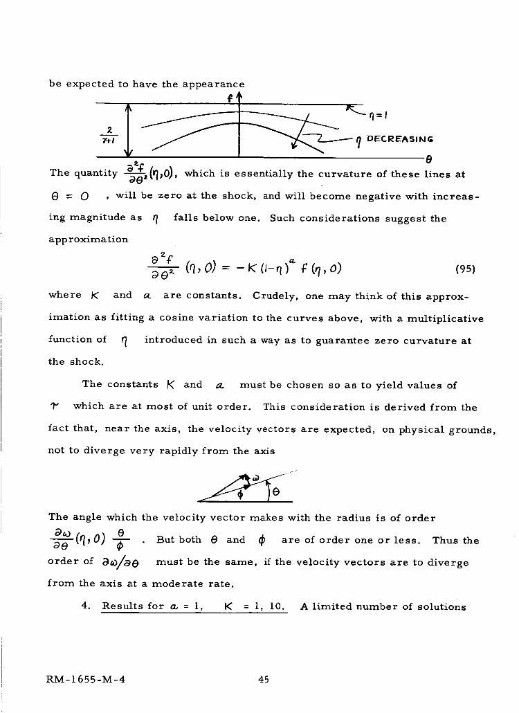
be expected to have the appearance
e
The quantity _0), which is essentially the curvature of these lines at
0 = 0 , will be zero at the shock,
ing magnitude as _ falls below one.
approximation
and will become negative with increas-
Such considerations suggest the
a_+" ),,._e _. (q, O) = - _ O-q ¢ (,?,0) (95)
where K: and _L are constants. Crudely, one may think of this approx-
imation as fitting a cosine variation to the curves above, with a multiplicative
function of _ introduced in such a way as to guarantee zero curvature at
the shock.
The constants b( and O. must be chosen so as to yield values of
1" which are at most of unit order. This consideration is derived from the
fact that, near the axis, the velocity vectors are expected, on physical grounds,
not to diverge very rapidly from the axis
The angle which the velocity vector makes with the radius is of order
a,o (q,o) ea-'-_ -_- But both e and _ are of order one or less. Thus the
order of Da)/D0 must be the same, if the velocity vectors are to diverge
from the axis at a moderate rate.
4. Results for a, = 1, K = l, 10. A limited number of solutions
RM- 1655-M-4 45
have been calculated, using the values a. = 1, K = 1. ° and 10. For a
given value of 7' , and selected values of N , Eqs. (89), (90), (91) and
(94) are integrated by a Runge-Kutta procedure, starting from the shock
values given by Eq. (92). The results found with C{. = 1, K = 10, 7' = 3,
and N =0,374,0.375, andO.376, are shown in Fig . 15a. The first graph on
this figure displays the denominator, whose vanishing identifies the "sonic"
point. The second plot shows the function H(q) , defined as
/, ) (Z /- N Z ¢ 1"'} /-N H(~) =l4Y-Q r1~ - -~- - Yf -~ cp (96 )
which, according to Eq ... (93), must also vanish at the sonic point if an accept-
able solution is to be achieved. This does occur at N = 0.375, and the cor-
responding distributions of 'f , ¢ +- , and 1"' are shown in the remaining
four graphs of Fig. 15a. Figure s 15b - e give similar re sults for 'd" = 2,
2.5 , 4, and 6. To illustrate the effect of I< , another calculation was done,
at 7' = 4, with I( = 1. 0 , and a.. = 1. The results, given in Fig. 16, differ
from those found for K = 10 chiefly by the fact that 1" is somewhat smaller,
and N is closer to 2/ S. This trend is qualitatively what would be expected;
a large r value of 1\ strengthens the influence of the pres sure gradient in
drawing material laterally away from the axis of symmetry. The fact that
more fluid is being extracted in this direction acts to retard the shock motion,
i. e. , N is decreased.
5. Comparison with the Symmetric Solution . The values of N found i
the above calculations were in all cases quite close to the value 2/5 that applie
for the symmetric, constant-energy solution . Furthermore, the quantity 'I
does not attain an appreciable value until some distance away from rt = 1,
whe re the density has fallen to a low value. Thus we might expect that, near
RM-l65S-M-4 46
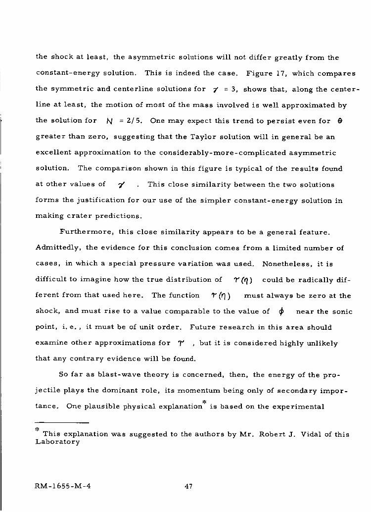
the shock at least, the asymmetric solutions will not differ greatly from the
constant-energy solution. This is indeed the case. Figure 17, which compares
the symmetric and centerline solutions for _' = 3, shows that, along the center-
line at least, the motion of most of the mass involved is well approximated by
the solution for _ = 2/5. One may expect this trend to persist even for _)
greater than zero, suggesting that the Taylor solution will in general be an
excellent approximation to the considerably-more-complicated asymmetric
solution. The comparison shown in this figure is typical of the results found
at other values of 7' This close similarity between the two solutions
forms the justification for our use of the simpler constant-energy solution in
making crater predictions.
Furthermore, this close similarity appears to be a general feature.
Admittedly, the evidence for this conclusion comes from a limited number of
cases, in which a special pressure variation was used. Nonetheless, it is
difficult to imagine how the true distribution of 9" (q) could be radically dif-
ferent from that used here. The function _" (_) must always be zero at the
shock, and must rise to a value comparable to the value of _ near the sonic
point, i.e. , it must be of unit order. Future research in this area should
examine other approximations for "F , but it is considered highly unlikely
that any contrary evidence will be found.
So far as blast-wave theory is concerned, then, the energy of the pro-
jectile plays the dominant role, its momentum being only of secondary impor-
tance. One plausible physical explanation _" is based on the experimental
This explanation was suggested to the authors by Mr.Laboratory
Robert J. Vidal of this
RM- 1 655-M-4 47
observation (22) that targets struck by hypervelocity projectiles often acquire
momenta many times that of the projectile, implying that the material ejected
from the target must also carry several times the projectile momentum. Thus
it appears that the momentum of the projectile itself makes only a minor con-
tribution to the over-all conservation process.
A corollary of this conclusion is that the conditions of hypervelocity
impact can be simulated _:_by any experiment which duplicates the energy of
the incident particle, irrespective of whether its momentum is correctly
matched. In particular, any intense source of short-pulse electromagnetic
radiation, such as the output of some currently available lasers, should be
capable of providing such a simulation. Such an experimental technique
appears to hold promise, and Appendix B discusses the basis for it in some
detail.
A final point must be made concerning the importance of energy versus
momentum. One must not infer, from our use of a constant-energy solution,
that "energy scaling" will hold, in the sense that crater volume is proportional
to the projectile's kinetic energy over a range of impact speeds. The fact is
V 113, duethat this theory predicts a result more nearly of the form ;_¢
to the fact that _ is allowed to vary with impact speed in an effort to fit
the equation of state over the whole range. And equally important, the pen-
etration law _c _ V'I_' sometimes described as "momentum scaling", does
The fact that such a simulation is possible was first pointed out to the
authors by Dr. Franklin K. Moore.
48
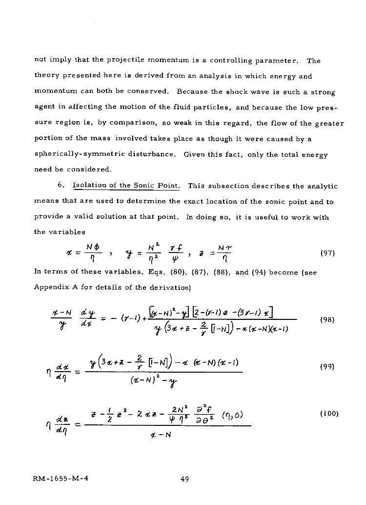
not imply that the projectile momentum is a controlling parameter. The
theory presented here is derived from an analysis in which energy and
momentum can both be conserved. Because the shock wave is such a strong
agent in affecting the motion of the fluid particles, and because the low pres-
sure region is, by comparison, so weak in this regard, the flow of the greater
portion of the mass involved takes place as though it were caused by a
spherically- symmetric disturbance.
need be considered.
6. Isolation of the Sonic Point.
Given this fact, only the total energy
This subsection describes the analytic
means that are used to determine the exact location of the sonic point and to
provide a valid solution at that point.
the variables
N$ N _ _
9 q,'
In terms of these variables, Eqs. (80),
In doing so, it is useful to work with
bgq"_ =_ (97)
q
Appendix A for details of the derivation)
(87), (88), and (94) become (see
- (r-,)+- z N]) (_-NX_-O71]-
(98)
(99)
I 2 2N = d=-g
¢-N
(lOO)
RM-1655-M-4 49
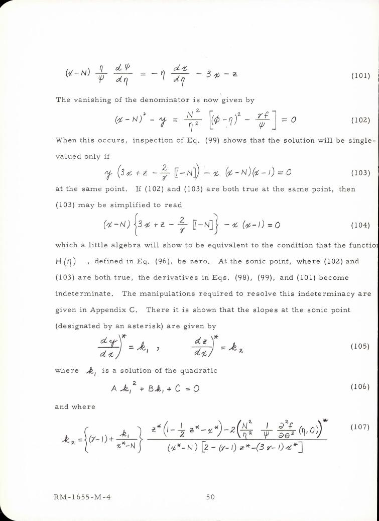
(101)
I
The vanishing of the denominator is now given by
2.-
(4 - N J' - "I" ~ 2 ~ 1> ~ 1 t - ~f ] = 0 (102 )
When this occurs, inspection of Eq. (99) shows that the solution will be single-
valued only if
l' (3/'c- + c. - ; [- NJ) ~ ',t; (t - N) (i - /) == 0 ( 103)
at the same point. If (102) and (103) are both true at the same point, then
(103) may be simplified to read
( ", - N) {3 4 H- ; [ - N]} - '" (,'" -!) ; 0 (104)
which a little algebra will show to be equivalent to the condition that the functio
H (0) ,defined in Eq. (96), be zero . At the sonic point, where (102) and
(103) are both true , the derivatives in Eqs . (98), (99), and (101) become
indeterminate. The manipulations required to resolve this indeterminacy are
given i n Appendix C. There it is shown that the slopes at the sonic point
(designated by an asterisk) are given by
where .,k., is a solution of the quadratic
2. A.k., + B..k / + C=-O
and where
RM-1655-M-4 50
(105)
(106 )
(107)
The functions A, B, and C appearing here are defined in Appendix C. They
depend on the sonic-point values of % , _ , _ , Q , _/J , j2, ¢ , and
9" , in addition to their dependence on N and 7' Having found _l and
_'2 , the formulas presented in Appendix C permit one to find _//_Q)_',-f
, , and jO i ) , and with these, the solution can be continued
smoothly through the sonic point. All that is required is the list of sonic-
point values referred to above. These can be found by extrapolating from a
set of solutions, at various values of _ , which approach more and more
closely to the sonic point.
shown, in the _ _ plane,
case F" = 3, with _< = I0,
locus of points at which Eq.
The procedure is illustrated in Fig. 18; here are
some of the numerical solutions obtained for the
_. = 1. The line marked "numerator = 0" is the
(I03) is satisfied, while that marked "denominator
= 0" is the locus of points satisfying (lOi). By extrapolating these two loci,
one may isolate the values _ and _* at which these two conditions are ful-
filled simultaneously. Similar extrapolations permit a determination of ___,
Q* , _" , 42 _, _ , and T _ These, in turn, fix the values of all the slopes,
so that the solution in the neighborhood of the singularity is complete. The
pair of separatrices shown in Fig. 18 was found by just this method.
Even with the solution determined in this fashion, there still remains
some question as to the precise value of N to be identified with it. For
practical application, there seems to be no point in specifying _q to five-or
six-figure accuracy. Thus, in carrying over results from the very fine scale
of Fig. 18 to the "practical" scale of Fig. 15a, the whole solution is tagged
with the number N = 0. 375. In actual fact, the solution shown in Fig. 1 con-
sists of the solution common to©.37500 and 0.37501 for _ _ 0.055, plus the
RM- 1655-M-4 51
extrapolation through the sonic point.
7. One-Dimensional Solution. The remainder of this section presents
a treatment of the disturbance field behind a strong planar blast wave. Becaus,
only one spatial dimension is present, a complete solution can be worked out.
This solution illustrates a method for simultaneous energy and momentum con-
servation in a self-similar solution. In addition, the formulas which are deriw
can be used to predict the craters that will be formed by the planar impact of
slab-or disk-shaped projectiles.
We make the perfect-gas approximation from the outset, choosing the
value of 7' in each case according to the method outlined above. The problem
is to determine the motion of a half-space of material resulting from the impul
sire application of a large pressure to its free surface, which is then exposed
to a perfect vacuum. The large impulsive pressure may be imagined to arise
in various ways, for example by the detonation of an explosive at the free sur-
face, or by the face-on impact of a disk-or slab-shaped projectile:
In the_ensuing motion, a strong shock wave propagates into the target, while
the free surface expands rapidly into the vacuum on the left
FREE
RM-1655-M-4 52
We may expect that a blast-wave solution will correctly describe the motion
when the time after impact is large compared to the time during which the
impulsive pressure was applied. Thus the free surface will lie, effectively,
at 4_ = -oo . The blast-wave solution of this problem has been discussed
by a large number of authors. (2_/'/7) An excellent review of these is given
by Mirels. (28)
The equations of motion are
+ (I08)
--+ _ ÷ -- = 0 (109)
In a self-similar solution, the dependent variables are assumed to depend only
on the similarity coordinate
?6
r__ _, (_.) (ill)
and are made dimensionless by the definitions
_- '_s _('r_) tO.-(,_Q _b(,q) "_-'/:)o _s rr('_) (I12)
As before, all time dependence is eliminated from the differential equations if
the shock advances as a power of the time
4_s = At" (I13)
Thus the similarity equations become
(C-q) ,+ _ _ =0 (I14)
RM-1655-M-4 53
(¢ -1) ~' -
- z /-N N
- --- ----
/- N N
f' if; + - - 0 r
Solve d for the d erivatives, these become
tjJ' /-N N
/-N .f tT
¥- - ¢(¢-~) 2-
(p-?) -
(.¢-ry){(~-0)2- '1'/1 " ¢ - 2 (tP-Q2
with the usual boundary conditions at the shock
¢(I) = f(l)::: 2
7'+-1 . )
t (I):=. 7+ I 7- 1
( 115)
(116 )
(11 7)
( 118)
(119)
( 120)
8. Determination of N Before Eqs. (117) - (119) can be integrated,
the parameter N must be specified. Just as in the axisymmetric case, the
criterion that determines N is that the solution pass smoothly through the
sonic point. The values of N that accomplish this feat ha ve been reported
in the literature for several values of -; , and a few more were calculated in
the present effort. These results are summarized in Table II, and are plotted
in F ig. 19 for 7 between 1. 0 and 10 . The distributions of pressure, density
and velocity that are obtained in this type of solution are shown in Fig. 20 for
the case t = 7/5, which has the exact solution(23), (27)
-* 5-~ tf = 0 (5 - 41 ) , ¢ = ~ (21- 1) , ~ = 7; (5 - 4 q ) (121 )
In further analogy to the axisymmetric case, the values of N which
RM-1655 -M-4 54
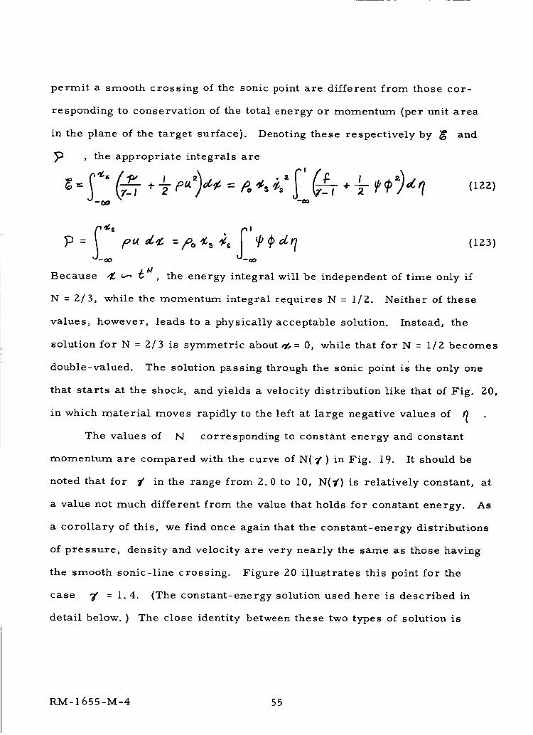
permit a smooth crossing of the sonic point are different from those cor-
responding to conservation of the total energy or momentum (per unit area
in the plane of the target surface). Denoting these respectively by _ and
, the appropriate integrals are
Because _ _-__ _ , the energy integral will be independent of time only if
N = 2/3, while the momentum integral requires N = I/2. Neither of these
values, however, leads to a physically acceptable solution. Instead, the
solution for N = 2/3 is symmetric about ,_= 0, while that for N = I/2 becomes
double-valued. The solution passing through the sonic point is the only one
that starts at the shock, and yields a velocity distribution like that of Fig. 20,
in which material moves rapidly to the left at large negative values of
The values of N corresponding to constant energy and constant
momentum are compared with the curve of N¿ _' } in Fig. 19. It should be
noted that for _' in the range from 2.0 to 10, N(?') is relatively constant, at
a value not much different from the value that holds for constant energy. _As
a corollary of this, we find once again that the constant-energy distributions
of pressure, density and velocity are very nearly the same as those having
the smooth sonic-line crossing. Figure 20 illustrates this point for the
case 7' = 1.4. {The constant-energy solution used here is described in
detail below. ) The close identity between these two types of solution is
RM- 1655 -M-4 55
exactly the same behavior as found above in our approximate treatment of
the centerline equations. The fact that the one-dimensional results are
found without approximation (there is no term analogous to ~ ) may be
taken as evidence for the generality of the conclusions reached in the axisym-
metric case.
9. Simultaneous Conservation of Energy and Momentum. There can
hardly be any question about the fact that the solutions which cross the sonic
line smoothly are the only acceptable ones. Having chosen N so as to
achieve such a smooth crossing, however, it is now impossible to satisfy
either of the conservation conditions, in the form given by Eqs. (122) and
(123). One means of resolving this difficulty is pointed out by Zeldovich. 25
He sugge sts that a small portion of the mas s be ignored in calculating the
total energy and momentum. This small mass, which originally lies at the
free surface and is strongly compressed during the initial stages of the
impact, acquires an entropy during the impact phase which is different from
that predicted by the similarity solution. This entropy depends only on con-
ditions at the shock, through integration of the differential equations, and
has nothing to do with the details of how the shock was formed. The entropy
of each particle remains constant , once it has been processed by the shock.
Thus the small portion of mass processed during the impact phase always
bears the imprint , so to speak, of this phase , and its motion is never cor-
rectly given by the similarity solution. Zeldovich I s argument is that in
seeking a self-similar solution, one should consider only that mass whose
motion is expected to be properly described by such a solution . His argument
derives considerable support from the fact that non-similar numerical
RM-1655-M-4 56
solutions (27) of the partial differential equations in _ and t fair
smoothly into his similarity solution when the time is large compared to
the duration of the impulsive pressure.
Mathematically speaking, the exclusion of this mass corresponds to
the replacement of the infinite lower limit in Eqs. (122) and (123) by a
finite number --_o (t) The introduction of a second free parameter per-
mits two conservation conditions to be satisfied. In the remainder of this
section, we work out in detail the relations that follow from neglecting this
small amount of mass.
The point --_o(_') (4_o > 0) , which forms the boundary of the neglected
mass, will be far to the left of the origin, since the mass neglected is small.
As a prelude to modifying the conservation integrals, then, we must first
determine the asymptotic formofthe solutionatlargenegative_vatlues.of _ ..
The key to finding such an asymptotic solution is to neglect the pressure-
gradient terms in the momentum equation, Eq. (ll5). We have seen before
that in these solutions the particle velocity is large at large negative _ ,
with a slope of order one. The pressure, on the other hand, is approaching
zero, signifying that its derivative is also becoming extremely small. Neg-
lecting this term yields the simple solution
q (124)
With _ known, the density
Finally, use of
i
can now be found from Eq. (114) as
I
I'Iand _ in (116) gives the asymptotic pressure formula
¢I-N 1126)
RM- 1655-M-4 57
Substituting back into Eqs. (i14)-(i16) shows that these approximations
are internally consistent.
The constants A 1and A 2 are not independent. Lees and Kubota! 29)
among others, have shown that the similarity equations in general have the
solution
where, from conditions at = i, K, is found to be
(7+1)K, = 2(7_i) (IZ8)
Equation (127) is derived by dividing (114) by _-q)//-_ , and by sub-
tracting from this the result of dividing (116) by 4(_-9)" The relationship
between A 1 andA 2 is found by substituting the asymptotic pressure and density
solutions into the general integral, Eq. (127). One finds that
A,A2=
K, {A(/_N )_ (129)
The quantity A 1 is found by integrating the similarity equations out to a large
negative value of _ , where the asymptotic behavior is reached. For
example, in the case _' - 1.4, the exact solution given in Eq. (121) shows
that A! = 3/16. In general, A! depends on 7' •
If we now neglect a small amount of mass To (mass per unit area), we
have
_-,_oe:) j,,_,_o(130)
RM-I 655-M-4 58
The integral here can be evaluated directly.
equation in the form
and integrating by parts, we find in general that
Thus
By writing the continuity
(131)
(13z)
!
tP_"t: - -'I) _-N-. _=,- N A,Ig.I (133)
and
II-T_-
m o = _ A JCN I-N. A, Ir/ol (1 34)
In order to make _/o independent of time, we must choose
I-N
rlo =-K_ t K:z >0
which give s
N
I-N /-N too"Z_° = A A' K"z hi
(135)
(136)
The parameter K 2 is the second free parameter which, with A, will permit
two conservation conditions to be satisifed.
If we neglect the mass 7_o in the energy-conservation integral, we have
,= 4- T _ _) dq (137)
%
RM- 1655-M-4 59
This integral, evaluated at the upper limit, yields a constant. At the
lower limit, we may use the asymptotic solution. Doing so reveals that
the internal energy contribution is negligible compared with the kinetic
energy term, and we have
=poAt"ZN** I + cons_.+O qoJ (13s)
The second term in the curly brackets comes from the upper limit,
term from the internal energy.
A' -_'-_")(. l_°l"'--a-
3" t-N
Carrying out the integration gives
+ const. + 0 rioj '-"
the third
as
A_ -(2-_.) ( I- N 3-__-._-__-_N
Tt _A, 2-_ K2 t ÷ const.+ 0 _ s-"_"))
(139)
_: becomes large (this is the limit at which we expect the blast-wave
solution to hold), the second and third terms here become negligible, since
N is less than 2/3, and 7, greater than one.
Neglecting the same amount of mass in the momentum integral gives
'1o
This integral can be evaluated exactly. Re-writing Eq. (115) as
_(¢_q)_, _-N V'¢+*'---o (141)N
RM-1655-M-4 60
and integrating, we have
_ I-N _, ¢_q.N
Consider onIy the last term.
d(¢-r 7) _' =-r
dq
An integration by parts gives
Substituting this in (142) gives the desired result
+ _'('¢ q) d9 =o
We've already seen in Eq. (1 32) that
(14Z)
(143)
(144)
- ") - [41Iz N, = _-qo
The right-hand side is found to be zero at the upper limit,
(145)
and at the lower
limit, the pressure contribution is small compared with the second term.
Thus
As Iqol_ , the integral vanishes. Thus, if we were to include all the mass,
and describe its motion by the self-similar solution, we would find zero net
momentum. In fact, Zeldovich takes this point of view, and apparently con-
siders the solution valid only for such a momentum condition. However, it
would appear to be more consistent to neglect mass in the momentum integral
as well. Doing so, we have
, I-N
= PoAA' a_-I K_.
(147)
RM-1 655-M-4 61
This relation, together with (1 39), enables us to find A and K 2 in terms of
and _ Note that the velocity of the impacting slab is related to these
parameters by
- 2 -3NA_'z (148)
while the neglected mass is of the same order as that of the projectile
N?. 0-N)(2-3N) N (2-_)2g. = #% AA, (z_-I)" _ ,-N _ (ZN-J)" _0 (149)
Solving for A and K z in terms of _ and
t<,_=f4A'(I-N)(2-3N)z(2N l)3 _?° I'-N_:>3
give s
(150)
A -- GO') _ ,_ (151)
where
f _ I-Hc.-(_,)= _.(2-3N) (_-N-,)_
2w-I +A l('l-N)l'2-3N)" " (15_-)
The actual solutions of the similarity equations have never been reported,
except for 3' = 1.4. Thus the variation of A with 3_ is not presently known.
When this information becomes available, it will be possible to compare the
final formula for the shock propagation
LRM-1655-M-4 62
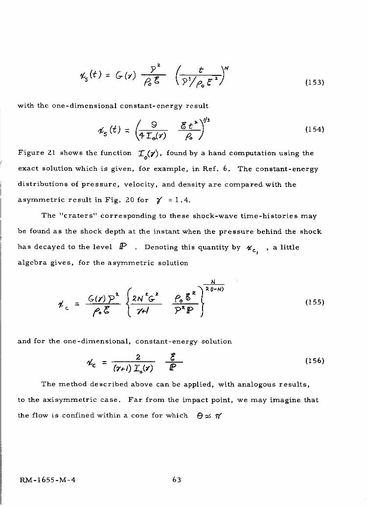
?_ f e S(153)
with the one-dimensional constant-energy result
cs (_.) = _-_,) _ /
Figure 21
(154)
shows the function :_0(_), found by a hand computation using the
exact solution which is given, for example, in Ref. 6. The constant-energy
distributions of pressure, velocity, and density are compared with the
asymmetric result in Fig. 20 for _/ = 1.4.
The "craters" corresponding to these shock-wave time-histories may
be found as the shock depth at the instant when the pressure behind the shock
has decayed to the level /P Denoting this quantity by _cl , a little
algebra gives, for the asymmetric solution
N
= (155)
and for the one-dimensional, constant-energy solution
'_ _ (156)_c = (7*0 Zo(_)
The method described above can be applied, with analogous results,
to the axisymmetric case. Far from the impact point, we may imagine that
the flow is confined within a cone for which _ _ 17"
RM-1655-M-4 63
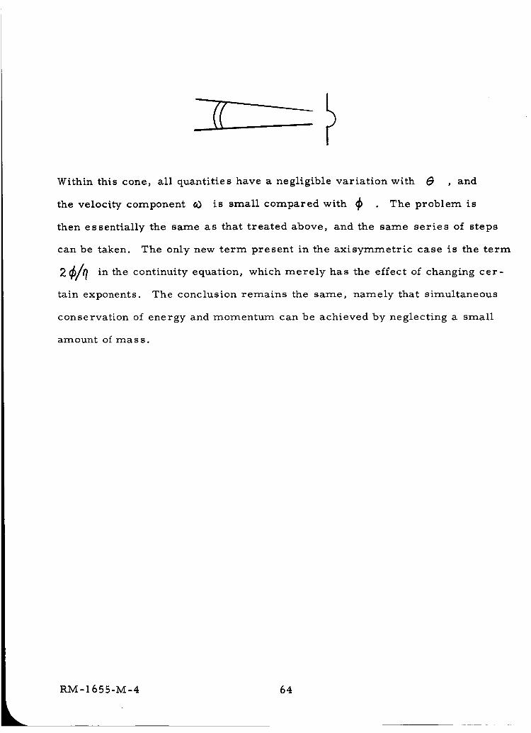
Within this cone, all quantities have a negligible variation with _ , and
the velocity component eO is small compared with _ . The problem is
then essentially the same as that treated above, and the same series of steps
can be taken. The only new term present in the axisymmetric case is the term
_/9 in the continuity equation, which merely has the effect of2 changing cer-
tain exponents. The conclusion remains the same, namely that simultaneous
conservation of energy and momentum can be achieved by neglecting a small
amount of mass.
64
II. BOUNDARIES FOR APPLICATION OF
THE BLAST WAVE ANALYSIS
A. The Space Vehicle Environment
The probability of collisions between space vehicles and meteoroids
of sufficient size to cause serious damage is too small and too variable to
allow convenient verification of ernpirical relationships by satellite experi-
ments. Therefore, it is necessary to improve prediction methods as much
as possible. Diverse sources of evidence can be used. Among these
sources are theoretical analyses, hypervelocity impact experiments, studies
of meteors, meteorites, meteor craters, and impacts of smaller meteoroids
on satellites, etc. A survey of information pertinent to this problem has
been published by Davison and Winslow. (31)
There is little agreement concerning the properties of the impacting
particles. Density estimates and assumptions range from 0.05 gm/cm 3 (32,33)
to 7.8 gm/cm 3.(34) Dense meteoroids are assumed to be of asteroidal origin
and low density meteoroids are assumed to come from comets. Whipple (35)
indicates that in space about 10% of sporadic meteoroids and not more than
20% of all meteoroids are of asteroidal origin. Of the meteoroids observed
in the vicinity of the earth about 50% are sporadic and 50_0 are in streams.
Relative velocities range up to 80 kilometers per second (assuming a par-
ticle in a closed orbit about the sun moving at 42 kilometers per second
approaching the earth in a direction opposite to the earth's motion at 30
kilometers per second, and colliding with a satellite moving at approximately
8 kilometers per second around the earth).
Whipple (32) states that the average velocity of photographic meteoroids
RM- 1655 -M-4 65
(36)is 28 krn/sec. The average velocity of smaller meteoroids is less.
Whipple (32) chooses a velocity of 15 km/sec for the smallest meteoro,ids
and assumes an arbitrary variation of velocity with magnitude. The fainter
meteoroids and those detected by radar observations tend to be more spora-
dic than the brighter meteoroids.(35) The mass of individual meteoroids
has been determined from brightness measurements on the Harvard Photo-
graphic Meteor Program. Meteors of visual magnitude zero were found to
have masses of the order of 25 grams. Based upon previous rough esti-
mates (32) of the penetration of meteoroids through structural materials,
the mass range of interest is from about 10 -2 to 10 -4 grams. Conversion
of visual magnitude to estimated mass is accomplished by the following
formula(34)_0
M--zsin which _¢_ is the magnitude
_?o is the mass of a zero magnitude meteor
and 7ff is the mass of the meteor
Photographic techniques are used for meteoroids down to the 5th magnitude.
The use of radio echo techniques may be extended to the 12th magnitude. (32)
A comparison with these mass estimates indicates that the most direct
evidence of interest for this penetration problem will come from radio
echo measurements.
In a study of photographic meteor wakes and trains McCrosky (37)
found that the particles which break off to cause the wake, have masses
of 10 -5 or 10 -6 grams. This evidence of the mode of fragmentation and the
size of fragments making up the larger meteoroids lends additional weight
to Whipple's suggestion that most of the meteoroids are low density bodies.
66
The original estimates of the density of photographic meteoroids have been
revised upward recently.(38) On the basis of new estimates of luminous
efficiency a one gram meteoroid having a velocity of 30 km/sec, has a density
of 0.44 gm/cm 3. These estimates result from experiments in which par-
ticles of known properties were projected down through the atmosphere and
simultaneously photographed from the earth.
B. Energy Transformation During Impact
An attempt has been made to present the hypervelocity impact pro-
blem as a chronological sequence of events involving realistic solids. This
approach leads to consequences that are difficult to unify in mathematical
terms but which, it is hoped, will give some insight into the nature of im-
pact processes.
During the brief period of meteoroid impact there are several stages
of energy transformation. It is important to consider the time history of
these stages because target characteristics will partially determine which
stage predominates in the production of damage to the space vehicle. Both
the meteoroid and the target may undergo polymorphic phase changes, how-
ever, the time occurrence of such phase transitions will not be simultaneous
unless the materials involved are identical. It is extremely unlikely that the
meteoroid will be identical in mechanical properties with the satellite target
mate rials.
Table 3 lists the stages of energy transformation undergone by the
meteoroid-target interface under hypervelocity impact conditions. Every
impact will not necessarily involve each of the listed steps since the impact
kinetic energy varies over a very wide range.
RM-1655-M-4 67
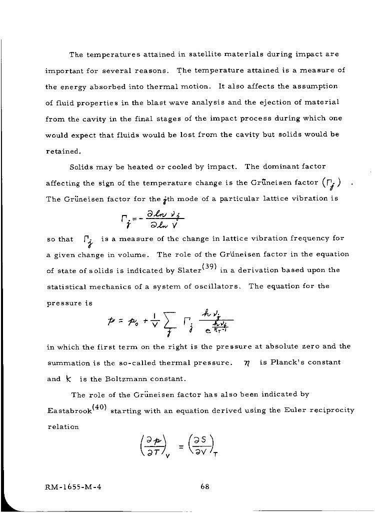
The temperatures attained in satellite materials during impact are
important for several reasons. The temperature attained is a measure of
the energy absorbed into thermal motion. It also affects the assumption
of fluid properties in the blast wave analysis and the ejection of material
from the cavity in the final stages of the impact process during which one
would expect that fluids would be lost from the cavity but solids would be
retained.
Solids may be heated or cooled by impact. The dominant factor
affecting the sign of the temperature change is the Gr_neisen factor (p_.)
The Gr_neisen factor for the #th mode of a particular lattice vibration is
so that _ is a measure of the change in lattice vibration frequency for
a given change in volume. The role of the GrUneisen factor in the equation
of state of solids is indicated by Slater (39) in a derivation based upon the
statistical mechanics of a system of oscillators. The equation for the
pressure is
in which the first term on the right is the pressure at absolute zero and the
summation is the so-called thermal pressure. -_ is Planck's constant
and k is the Boltzmann constant.
The role of the Gr{ineisen factor has also been indicated by
Eastabrook (40) starting with an equation derived using the Euler reciprocity
relation
68
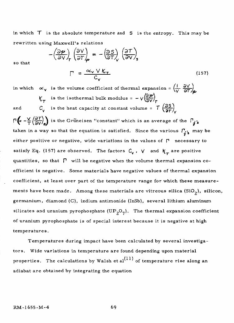
in which T
rewritten using Maxwell's relations
- -t. <:gv/7-so that
is the absolute temperature and S is the entropy. This may be
(157)
_V
C v
in which o¢ v is the volume coefficient of thermal expansion = (-_
_. is the isothermal bulk modulus = - V(_-v).,.v.,
and Cv is the heat capacity at constant volume = "T _'-'T)v
(= D(_-_)s) an average P_[11 -_ is the Gr_neisen "constant" which is of the 's
taken in a way so that the equation is satisfied. Since the various _'5 may be
either positive or negative, wide variations in the values of P necessary to
satisfy Eq. (157) are observed. The factors Cv , V and _7" are positive
quantities, so that P will be negative when the volume thermal expansion co-
efficient is negative. Some materials have negative values of thermal expansion
coefficient, at least over part of the temperature range for which these measure-
ments have been made. Among these materials are vitreous silica (SiO2), silicon,
germanium, diamond (C), indium antimonide (InSb), several lithium aluminum
silicates and uranium pyrophosphate (UP207). The thermal expansion coefficient
of uranium pyrophosphate is of special interest because it is negative at high
temperatur e s.
Temperatures during impact have been calculated by several investiga-
tors. Wide variations in temperature are found depending upon material
properties. The calculations by Walsh et al (11) of temperature rise along an
adiabat are obtained by integrating the equation
RM- 1655 -M-4 69
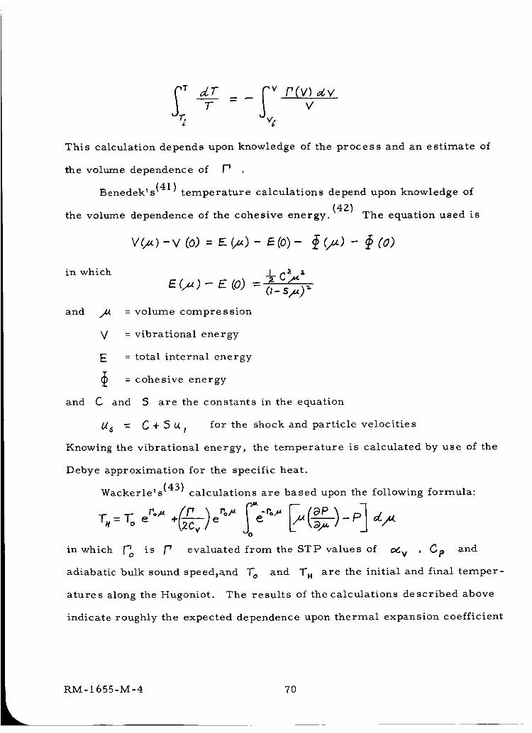
T
v_
I" ( v ) ,_ vv
This calculation depends upon knowledge of the process and an estimate of
the volume dependence of P
Benedek' s(41) temperature calculations depend upon knowledge of
(42)the volume dependence of the cohesive energy. The equation used is
v(_)-v (0)= e (_)- _(0)- _ (_)- i_(0)
in which
and
E(,,.)- E (o) = o-s_) _-
_4 = volume compression
V = vibrational energy
E = total internal energy
= cohesive energy
and C and 5 are the constants in the equation
_ = C + 5 _I for the shock and particle velocities
Knowing the vibrational energy, the temperature is calculated by use of the
Debye approximation for the specific heat.
Wackerle's (43) calculations are based upon the following formula:
P e- °_' _qP - P-_
in which _o is p evaluated from the STP values of od v , Cp and
adiabatic bulk sound speed_a_nd T o and T_ are the initial and final temper-
atures along the Hugoniot. The results of the calculations described above
indicate roughly the expected dependence upon thermal expansion coefficient
RM-1655-M-4 70
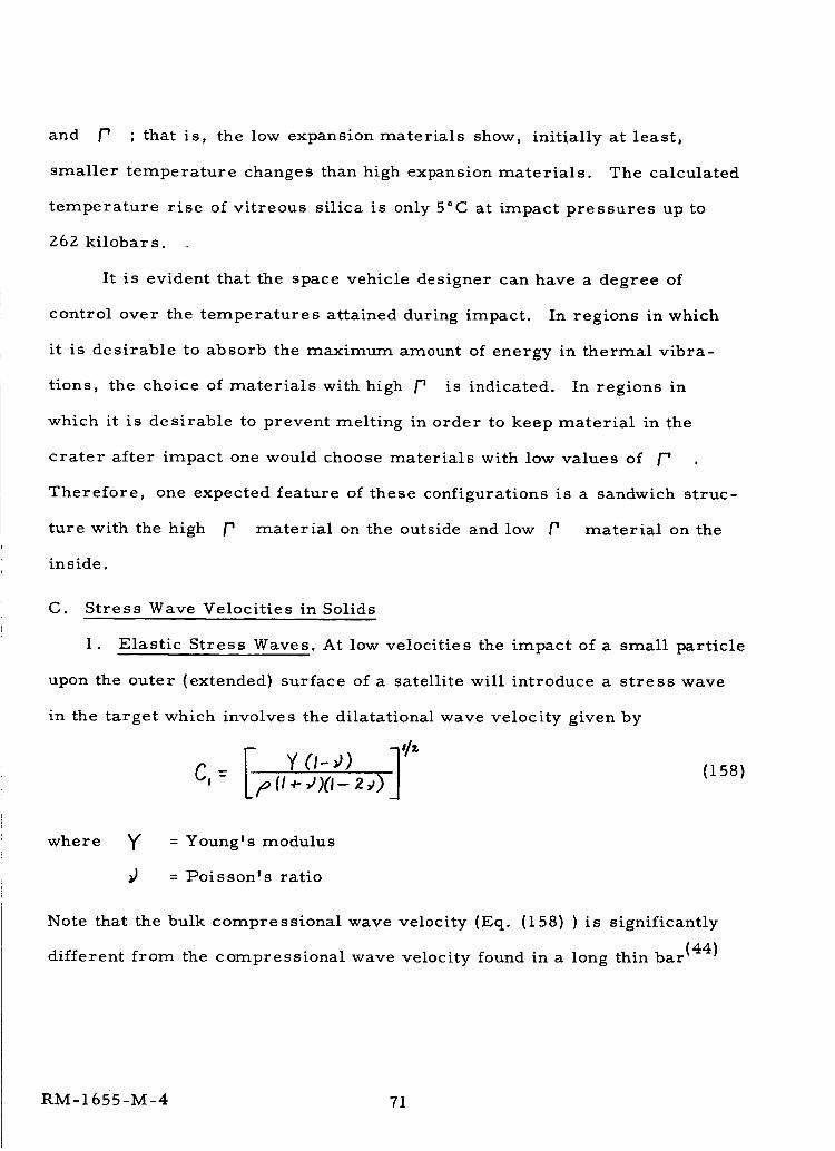
and [' ; that is, the low expansion materials show, initially at least,
smaller temperature changes than high expansion materials. The calculated
temperature rise of vitreous silica is only 5°C at impact pressures up to
262 kilobar s.
It is evident that the space vehicle designer can have a degree of
control over the temperatures attained during impact. In regions in which
it is desirable to absorb the maximum amount of energy in thermal vibra-
tions, the choice of materials with high p is indicated. In regions in
which it is desirable to prevent melting in order to keep material in the
crater after impact one would choose materials with low values of F'
Therefore, one expected feature of these configurations is a sandwich struc-
ture with the high p material on the outside and low P material on the
inside.
C. Stress Wave Velocities in Solids
1. Elastic Stress Waves. At low velocities the impact of a small particle
upon the outer (extended) surface of a satellite will introduce a stress wave
in the target which involves the dilatational wave velocity given by
I_ W ('- _)) ] '/z`l.__)(,- 2,p)_(:,= (lS8)
where ¥
P
= Young's modulus
= Poisson's ratio
Note that the bulk compressional wave velocity (Eq. (158)) is significantly
different from the compressional wave velocity found in a long thin bar (44)
RM-1655-M-4 71
(i.e., where the bar cross section is small compared with a wave length).
The change in velocity which occurs as the wavelength approaches the cross-
sectional dimension is due to the increase in lateral restraints. For the
high frequencies associated with short duration meteoroid impact, the higher
dilatational wave velocity is more appropriate. In isotropic solids, Poisson's
ratio is always less than one-half and greater than zero, hence Cl _ C o
(the velocity in a long thin bar).
For isotropic solids, the fastest elastic wave travels with the bulk
dilatational wave velocity. Hence, meteoroid impact will be in the hyper-
velocity region if the impact velocity is greater than the fastest elastic wave
velocity in the target material given by Eq. (158).
In Table 4, the bulk dilatational wave velocity is tabulated for several
plastics, metals_ ceramics and glasses. Beryllium has the highest stress
wave velocity among the metallic elements. Corundum ( oc - alumina) and
silicon carbide are among the highest for ceramic bodies. Therefore, im-
pact velocities above 13 kilometers per second are probably in the hyper-
velocity region for elastic wave propagation in all materials.
The transition region between subsonic and supersonic velocities is
defined here as the velocity range lying above the lowest elastic wave
velocity (Rayleigh waves for short duration impact) and below the highest
elastic wave velocity (bulk dilatational wave velocity). The transition
region will become broader as Poisson's ratio increases towards 0.5 so
that different target materials will have both different critical impact velo-
cities (i.e., where V-- C l ) and different transition velocity ranges.
In compression, most materials exhibit an increasing Young's modulus
RM-I 655-M-4 72
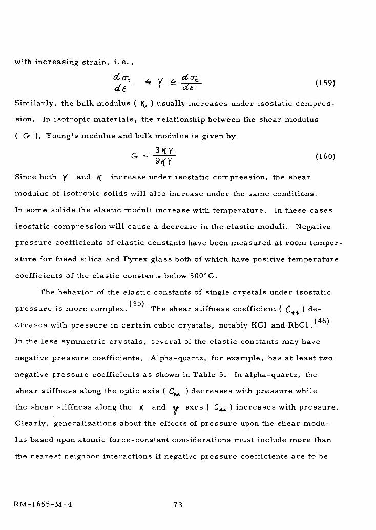
with increasing strain, i.e. ,
Similarly, the bulk modulus ( _ ) usually increases under isostatic compres-
sion. In isotropic materials, the relationship between the shear modulus
( _ ), Young's modulus and bulk modulus is given by
G- (16o)
Since both y and _ increase under isostatic compression, the shear
modulus of isotropic solids will also increase under the same conditions.
In some solids the elastic moduli increase with temperature. In these cases
isostatic compression will cause a decrease in the elastic moduli. Negative
pressure coefficients of elastic constants have been measured at room temper-
ature for fused silica and Pyrex glass both of which have positive temperature
coefficients of the elastic constants below 500°C.
The behavior of the elastic constants of single crystals under isostatic
(45)pressure is more complex. The shear stiffness coefficient (_+¢) de-
creases with pressure in certain cubic crystals, notably KCI and RBC1.(46)
In the less symmetric crystals, several of the elastic constants may have
negative pressure coefficients. Alpha-quartz, for example, has at least two
negative pressure coefficients as shown in Table 5. In alpha-quartz, the
shear stiffness along the optic axis { _ ) decreases with pressure while
the shear stiffness along the K and _ axes ( C_ ) increases with pressure.
Clearly, generalizations about the effects of pressure upon the shear modu-
lus based upon atomic force-constant considerations must include more than
the nearest neighbor interactions if negative pressure coefficients are to be
RM- 1655-M-4 73
predicted.
2. Plastic Stress Waves. The elastic wave velocity relations given
in the previous section are valid for small amplitude stress waves. With
increasing stress-wave intensities, the velocity relations become nonlinear
functions. These nonlinearities arise from two different factors. The first
is the nonlinearity caused by higher order terms in the stress-strain relations
for finite deformations. (47) The theory for finite amplitude stress waves is
a complete subject in itself and will not be treated here. The second is the
nonlinearity associated with plastic deformation where the tangent modulus
(_0_/_ associated with infinitesimal stress)
of elasticity 6 ,_,amplitude
waves is dependent upon the strain. High-intensity stress waves whose
stress amplitude exceeds the elastic limit are known as plastic waves. In
general, the plastic-wave velocity is dependent upon both the strain and the
strain rate. (48)
Strain-rate effects in metals have received extensive experimental
study. Each class of metals or alloys appears to behave in a different
manner. Dislocation theory (49) provides a theoretical explanation of strain-
rate effects. The evidence suggests that for crystalline materials, strain
rate dependence is associated with motions of dislocations. Dislocations
are arrays of lattice-point defects which may take several different forms,
e.g., a line, a loop, a helix, a screw or combinations thereof. Each type
of dislocation has a characteristic velocity which is dependent upon the host
lattice structure and the absolute temperature. Hence a general discussion
of strain-rate dependence becomes quite complex. The possibility of dis-
location motion at velocities above the highest elastic stress wave velocity
RM- 1655-M-4 74
is the subject of considerable controversy. If the velocity of any disloca-
tion motion may not exceed the fastest stress wave velocity ( _! ), under
hypervelocity impact conditions, dislocations ahead of the penetrating pro-
jectile are not free to move and the intrinsic strength or dynamic yield
point is determined by the interatomic forces alone.
Plastic waves have been studied extensively under tension impact
conditions. Because of the decreasing slope of _O'_/_E with increasingg
strain for most metals, the plastic wave portion of a tension impact distur-
bance travels with a lower velocity than the elastic wave portion causing the
stress pulse to become elongated at positions remote from the point of dis-
turbance. (44)
3. Shock Waves in Solids. Since the elastic moduli for isotropic solids
usually increase under compressive stress, the several stress wave velocities
will also increase with compressive stress. Thus, attempts to propagate in-
tense stress waves will result in the generation of a discontinuous wavefront.
Stress waves which require discontinuous functions to describe the wavefront
are known as shock waves. The shock wave velocity will usually be greater
than the corresponding elastic wave velocity in a given isotropic solid.
In a gaseous medium, the thickness ( Ss ) of an intense shock front is
equal in length to a few mean free paths of the gas molecules.(50) By
analogy, the shock front thickness in a solid medium is on the order of a
few phonon mean free paths. In gases, thermodynamic equilibrium is reached
The term shock wave as used in the literature generally refers to an intense
bulk-dilatational wave. However, in the broader context used here, shear-
mode shock waves are also possible.
RM-1655-M-4 75
only at finite distances behind the shock front. Similarly, thermodynamic
equilibrium in solids behind an intense shock front requires distances
equivalent to several phonon mean free paths. The lack of thermodynamic
equilibrium within the shock front can be illustrated by comparison of the
impact velocity with the instantaneous velocity of lattice vibrations (near room
temperature). Assuming, for convenience, that the lattice vibrations behave
as harmonic oscillators, (i. e., ×=_U_C ) then the instantaneous lattice-
point velocity _/_f will be given by/
d×-- = c0 cot
where &O = 2._r;
= frequency of lattice vibrations
= maximum displacement of the vibrating atom within the
lattice unit cell
For a maximum displacement of one-tenth thelattice spacing ( a6 ), a lattice
frequency of I013 cycles per second (infrared band), and a nominal lattice
spacing of 5 angstroms, the maximum instantaneous lattice-point velocity is
Thus, the maximum lattice-point velocity is less than the impact velocity
in the hypervelocity region. This simple calculation is sufficient to illustrate
that even on an atomic scale, impact velocities in the supersonic range repre-
sent a gross disturbance to the lattice point displacements at the impact
interface.
The phonon mean free path (A.) in alpha-quartz at 0°C is 40 x 10 -8 cm
76
or about 8 lattice spacings (51) given by
3/<_. -
where K = thermal conductivity
H = heat capacity per unit volume
C = "mean sound velocity" - space averaged elastic wave velocity
The shock front thickness ( _s ) in alpha-quartz would be in the order of one
micron near room temperature ( _;s _-_ )"
D. Collisions Involving Porous Bodies
The calculations involving porous meteoroids are especially important
because of the relatively great frequencyofoccurrence of cometary meteoroids.
Impacts and shock waves in porous materials have been studied to a very
limited extent. Altshuler et al (10) obtained shock wave data for porous
(specific gravity = 5.52) and non-porous (specific gravity = 7.85) iron to
5 x 10⁶ atm. The equation of state for tuff, a porous rock, is also available. (5'8)
In the following sections, the conditions during impacts between porous
materials and non-porous materials are compared to indicate the differences
caused by the presence of pores.
Case I - Impacts of Porous Meteoroids Against Solid Surfaces
Calculations of the shock-wave characteristics for impacts between
porous and solid iron, using Altshuler's data and assuming planar shock waves,
will be used to indicate the effect of porosity. The Hugoniots are shown in
Figure 25. The presence of porosity results in an increase in the pressure
and energy per unit mass at a given density of material in the shock front.
Since the pressures in the meteoroid and space vehicle surfaces must be
equal at the point of impact, the shock and particle velocities can be deter-
RM-1655-M-4 77
mined. For example, consider the case of a porous iron meteoroid colliding
with a solid iron space vehicle surface at an impact velocity of 9 km/sec.
If we ask which combination of particle velocities for the porous and non-
porous materials add up to the impact velocity, we find using Figure 26
that at equal interface pressure the particle velocity ( t_, ) in the solid vehicle
skin is 3.8 km/sec. While the particle velocity ( t_ I ) in the porous "meteoroid"
is 5.2 km/sec. The shock velocities and density ratios can be read from
Figure 27. The energy per unit mass can be calculated from
e a - 27o
The results are given in Table 6. The energy per unit mass in the Porous
ll"meteoroid" (1.4 x l0 ergs/gm).is significantly greater than that in the solid
vehicle skin (0.76 x l0 II ergs/gm). It seems likely that this energy distri-
bution will result in decreased meteoroid penetration due to greater evaporation
which in turn is due to greater conversion of kinetic energy into thermal energy
at impact. This conversion into thermal energy is illustrated in Figure 28,
which has been revised fromAltshuler's paper. Curve _-_ is the schema-
tic shock compression curve for a non-porous material. The thermal energy
(E r) added to a unit mass compressed to _ is indicated by the area of
triangle _1_7_ less the area of triangle _'l_ which is work required to
compress the material to _r at 0°K_ (E_,). The same type of material
(i.e., iron) containing pores will be compressed by shock waves to various
states along ,zrm_z. If we neglect the small amount of energy required to re-
move the pores by compression at absolute zero, (indicated by the dotted
line), the extra thermal energy added (_E T) to the porous material to com-
press it to n_l is given by the area _a__. Presumably, the
RM- 1655-M-4 78
increased temperature and pressure at _ will cause increased evaporation
or melting of the porous material when the pressure is released.
Case s II-V
When a non-porous meteoroid collides with a porous vehicle skin
(Case II), the particle velocity in the meteoroid is less than that in the vehicle
skin (see Table 5). The shock velocities and density ratios are also reversed
and the sign of the internal energy difference changes. When a non-porous
meteoroid collides with a non-porous vehicle skin (Case III) at the same velocity
as the preceding cases, the resulting interface pressure is increased and the
internal energy increase per unit mass is the same in both bodies. When a
porous "meteoroid" collides with a porous vehicle skin (Case IV), the initial
interface pressure is lower than in the previous cases and the internal energy
increase per unit mass is the same in both bodies and is roughly the same as
the value in Case III. To increase the impact velocity so that the initial inter-
face pressure is the same as that in Case III with porous materials requires
an impact velocity of 12.2 Km/sec. In this case (Case V) the particle and
shock velocities and the density ratios are increased. The internal energy
increases per unit mass in this case is 2.0 x l0 II ergs/gm.
It is evident that even a small amount of porosity significantly effects
the shock variables. The most important of these effects is the increased
thermal energy per unit mass. In the initial phase of crater formation, the
increased energy converted to thermal motion becomes unavailable to do
structural damage.
If the materials are very porous, as seems to be the case for cometary
meteoroids, the impact area is increased considerably and the initial interface
RM-1655-M-4 79
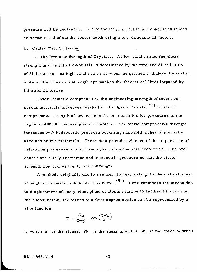
pressure will be decreased. Due to the large increase in impact area it may
be better to calculate the crater depth using a one-dimensional theory.
E. Crater Wall Criterion
1. The Intrinsic Strength of Crystals. At low strain rates the shear
strength in crystalline materials is determined by the type and distribution
of dislocations. At high strain rates or when the geometry hinders dislocation
motion, the measured strength approaches the theoretical limit imposed by
interatomic forces.
Under isostatic compression, the engineering strength of most non-
porous materials increases markedly. Bridgeman's data (52) on static
compressive strength of several metals and ceramics for pressures in the
region of 400,000 psi are given in Table 7. The static compressive strength
increases with hydrostatic pressure becoming manyfold higher in normally
hard and brittle materials. These data provide evidence of the importance of
relaxation processes to static and dynamic mechanical properties. The pro-
cesses are highly restrained under isostatic pressure so that the static
strength approaches the dynamic strength.
A method, originally due to Frenkel, for estimating the theoretical shear
strength of crystals is describedby Kittel.(51) If one considers the stress due
to displacement of one perfect plane of atoms relative to another as shown in
the sketch below, the stress to a first approximation can be represented by a
sine function
0" _ 2_rd k?]
in which 0_ is the stress, G- is the shear modulus, a. is the space between
RM-1655-M-4 80
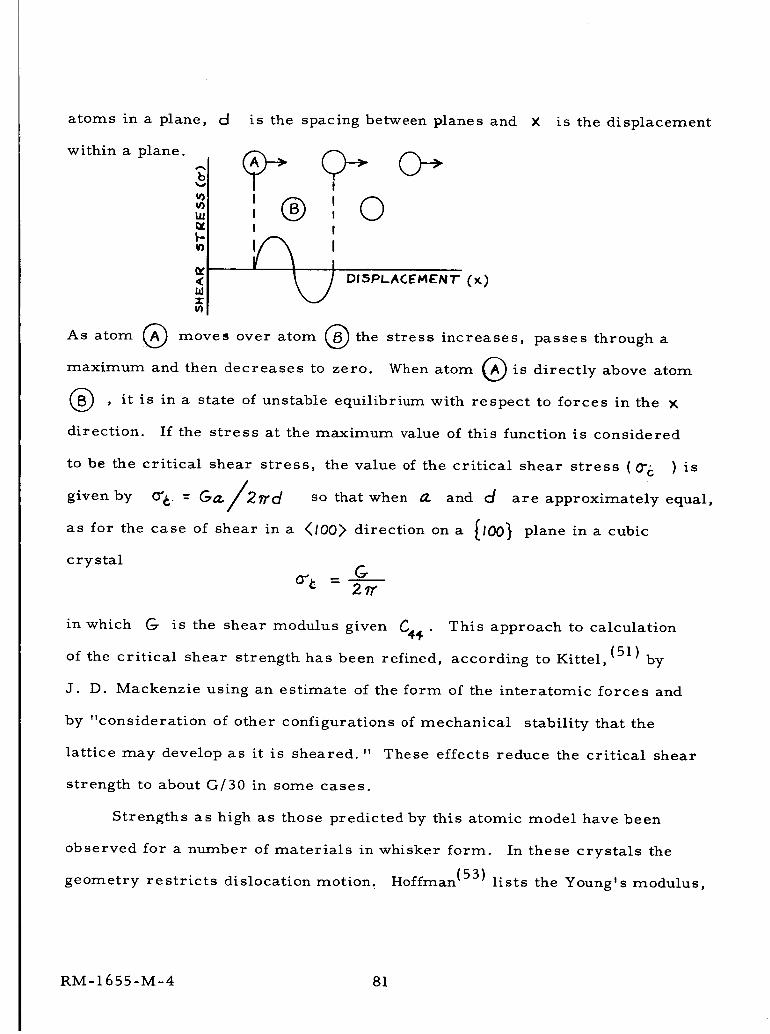
atoms in a plane, d is the spacing between planes and X is the displacement
within a plane.
Ill
<
=¢u}
I
, ', ©I I
DISPLACEMENT (x)
As atom @ move, over atom Q the stress increases, passes through a
maximum and then decreases to zero. When atom _ is directly above atom
, it is in a state of unstable equilibrium with respect to forces in the X
direction. If the stress at the maximum value of this function is considered
to be the critical shear stress, the value of the critical shear stress (0-6 ) is
given by O'_ = _/2_d so that when 0_ and d are approximately equal,
as for the case of shear in a </00> direction on a
crystal
I00} plane in a cubic
in which G is the shear modulus given C4_ .
of the critical shear strength has been refined,
This approach to calculation
according to Kittel, (51) by
J. D. Mackenzie using an estimate of the form of the interatomic forces and
by "consideration of other configurations of mechanical stability that the
lattice may develop as it is sheared." These effects reduce the critical shear
strength to about G/30 in some cases.
Strengths as high as those predicted by this atomic model have been
observed for a number of materials in whisker form. In these crystals the
geometry restricts dislocation motion. Hoffman (53) lists the Young's modulus,
RM- 1655-M-4 81
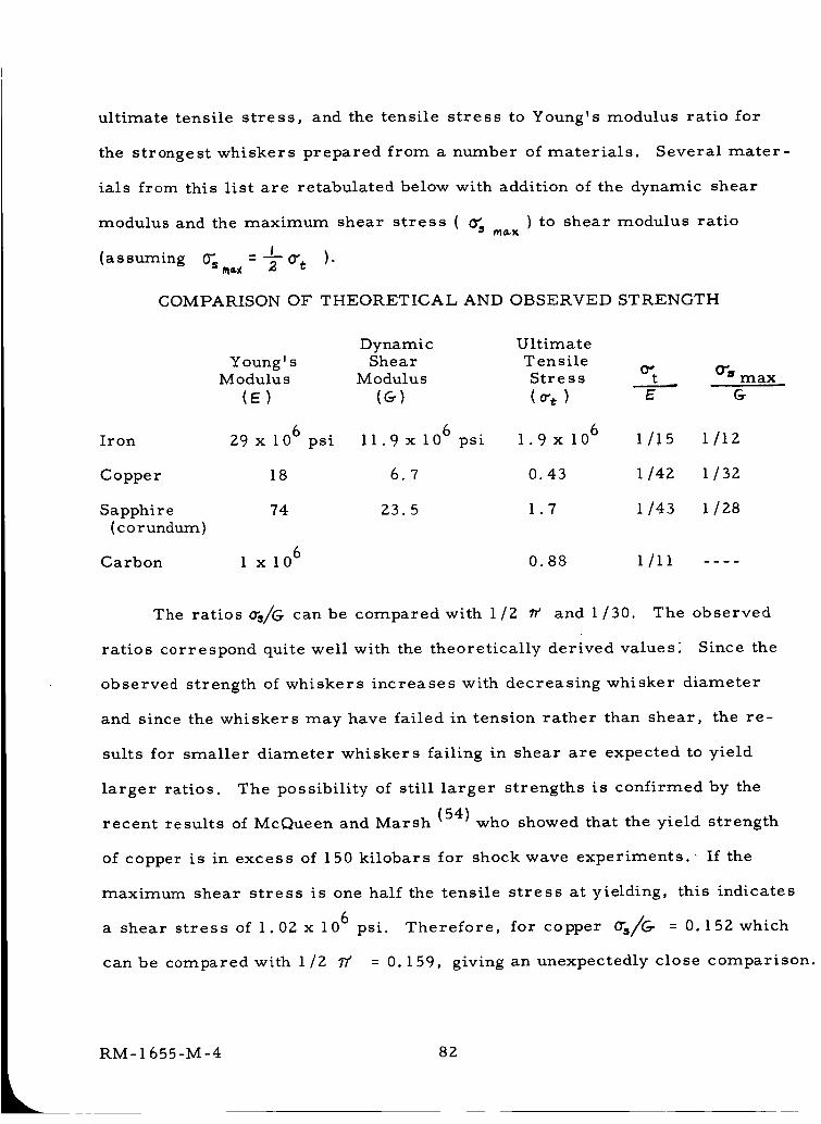
ultimate tensile stress, and the tensile stress to Young's modulus ratio for
the strongest whiskers prepared from a number of materials. Several mater-
ials from this list are retabulated below with addition of the dynamic shear
modulus and the maximum shear stress ( 0"5 m_K ) to shear modulus ratio
_ l(assuming _,--_-O" t ).
COMPARISON OF THEORETICAL AND OBSERVED STRENGTH
Iron
Copper
Sapphire
(corundum)
Carbon
Young' sModulus
(E)
29 x 106 psi
18
74
i xlO 6
Dynamic UltimateShear Ten sile
Modulus Stre s s O't 0"8 max
(G) E
11.9 x 10⁶ psi 1.9x 10⁶
6.7 0.43
23.5 1.7
1/!5 l/1Z
1/42 1 /32
1/43 1 128
0.88 I/II
The ratios o's/G can be compared with 1/2 _/ and 1/30. The observed
ratios correspond quite well with the theoretically derived values: Since the
observed strength of whiskers increases with decreasing whisker diameter
and since the whiskers may have failed in tension rather than shear, the re-
suits for smaller diameter whiskers failing in shear are expected to yield
larger ratios. The possibility of still larger strengths is confirmed by the
recent results of McQueen and Marsh (54) who showed that the yield strength
of copper is in excess of 150 kilobars for shock wave experiments.- If the
maximum shear stress is one half the tensile stress at yielding, this indicates
a shear stress of 1.02 x 10⁶ psi. Therefore, for copper 0"s/G = 0.152 which
can be compared with 1/2 7/" = 0. 159, giving an unexpectedly close comparison.
LRM-I 655-M-4 82
McQueen and Marsh also indicate a critical pressure on the Hugoniot which
corresponds to the yield point (_ZP//eZV ' = 0). The negative pressure at this
point is a theoretical tensile strength. These theoretical strengths, with
corresponding shear stresses and other data are given in Table 8. The cal-
culated values of 0"%/_ based on this information are somewhat larger than
1/2 77' Based upon all of the information given above, the critical shear
strength = G/2_T is considered to be the best available value for the shear
strength at high strain rates.
2. The Influence of Shear Strength on Crater Formation. It has been a
common practice in fitting impact equations to experimental data to normalize
the impact velocities to the velocity of sound in the undisturbed medium. The
presence of a transition region, the velocity range near the sound velocity in
which there is a change in the relationship between crater depth and impact
velocity, has served as a partial justification for this practice. However, the
reason for the change in the relationship between crater depth and impact
velocity has not been clear. It seems reasonable that the processes governing
failure (i. e. , crater formation) should depend primarily on the properties of
the disturbed medium rather than the undisturbed medium since there is a sub-
stantial pressure discontinuity at the shock front even after the crater has
reached its final form.
Pressure profiles for impact of iron on iron and a natural meteoroid on
tuff have been calculated numerically by Bjork.(5' 8) These profiles indicate,
as might be expected, that the pressure gradients in the disturbed material
are greatest near the crater lip. It seems likely that shearing of the material
at the crater lip is the first requirement for ejection of material from the crater,
RM-I 655-M-4 83
at least in regions far from the impact point.
If one considers a cube of material at the crater lip, and assumes that the
material on the inside (toward the impact point) has already been removed or
melted, it is possible to visualize the shear stresses on this material. The
cube is pressed from behind by the high pressure material in the cavity. Motion
is resisted by the pressure of the material moving ahead of it and by inertial
forces and shear stresses. As the crater wall reaches its final position, the
motion of material slows down and stops while the pressure gradients and shear
stresses remain substantial so that, at this point, the inertial forces in the
tangential direction can be neglected. Therefore, the principal factors deter-
mining whether or not the material at the crater lip will be ejected are the
pressure gradient tangential to the wave front and the shear stresses in the
wave front.
It is obvious that the choice of a cube as the beam or ring element on which
the forces act is arbitrary. At the very high pressure gradients established
near the impact point these forces will act on a very thin ring since the material
nearer the impact point will have been ejected (Figure 29a). As the intensity of
the shock decreases, the thickness of the ring on which these forces act will
increase (Figure 29b). But the increase in thickness is limited because the
pressure decreases sharply toward the open crater (Figure 29c). This increase
in thickness is consistent with the observation that small fragments are ejected
from the crater early in the process at high velocities and large fragments at
(2Z)low velocities later in the process. Reasonable dimensions for the radial
distance over which the pressure difference acts to cause shear are also in-
dicated by the thickness of the crater lip after crater formation is complete
RM-1655-M-4 84
(Figure 29d).
3. The Dynamic Shear Modulus and Intrinsic Strength of Structural
Materials. An examination of the elastic property data in Tables 4, 5, and 7
indicates that high values of dynamic shear modulus are observed for low den-
sity metals such as beryllium, refractory metals such as tungsten, and for
ceramics such as corundum (A1203) and silicon carbide which contain elements
from the center of periods 2 and 3 of the periodic table. If one calculates the
intrinsic shear strength as a fraction of the shear modulus as suggested by
Frenkel and Mackenzie, the low density metals and ceramics will have the
highest strength to specific gravity ratios. The intrinsic shear strength (G/£,,)
to specific gravity ratio of beryllium is 1.85 x 10⁶ psi and for silicon carbide
it is 1.23 x 10⁶ psi. A comparable value for 34T stainless steel is
0.22x 10⁶ psi.
There remains some uncertainty with respect to the choice of shear
modulus values. The values chosen here are for polycrystalline samples.
However, almost all single crystals show a substantial degree of elastic aniso-
tropy. The effect of anisotropy on crater formation has been illustrated by
Eichelberger and Gehring.(55) If the impacting particles are much larger than
the individual grains of the target material so that the forces resulting from
impact are spread over many grains, the correct choice would seem to be the
properties of the polycrystalline body. In intermediate cases, in which failure
can occur due to forces spread over only a few grains, the choice is uncertain.
Some materials are very weak in shear in particular crystal directions. For
example, the shear 'moduli for beta brass (CuZn) given by Lazarus (56) are
C44 = 8.24 x 10¹¹ dynes and 1/2 (Cll - C12) = 0.975 x 10¹¹ dynes/cm 2.2cm
RM- 1655-M-4 85
This large anisotropy is characteristic of body centered cubic structures com-
posed of metals whose ions have closed shells (Zener57). In the case of large
grain size and substantial anisotropy, it may be important to use the smallest
shear modulus to calculate the intrinsic strength.
4. Variation of the Dynamic Shear Modulus with Temperature and
Pressure. The effect of temperature and pressure on the shear modulus, may
be important in calculation of the intrinsic strength. The temperature is of
direct importance in the case of space radiators operated at temperatures high
enough to affect the mechanical properties of the materials used. The shear
modulus of materials usually decreases with increasing temperature but in a
few cases, for example vitreous silica, an increase is observed. The tempera
ture variation of the shear modulus is influenced by the change in shear modulul
with volume at zero temperature, the thermal energy and the thermal expansior
The effect of target temperature on crater volume has been illustrated by
Eichelberger and Gehring (55) based mainly on data given by Allison et al.(58)
The results indicate a marked dependence of crater volume on the properties
of target materials as these properties are affected by temperature. The metal
used were lead, aluminum, copper, zinc, and cadmium. These targets were
impacted at 5.01 Km/sec. The crater volumes increased substantially with
increasing target temperature.
The variation of the shear modulus of pure aluminum as a function of
temperature has been studied by K@.(59) The shear modulus decreases linearly
with temperature for aluminum single crystals and there is a pronounced de-
crease in shear modulus of polycrystalline aluminum in the temperature range
from Z00-400°C. Internal friction measurements at low frequencies indicate
RM-1655-M-4 86
that this variation in polycrystalline aluminum is caused by grain boundary
relaxation.
The internal friction measurements indicate a long relaxation time for the
grain boundary: movement. Therefore, the linear variation in shear modulus
shown for the single crystal sample is more appropriate than the values for
pure polycrystalline aluminum for use with samples at the high strain rates
characteristic of meteorite impact.
Similar data for beryllium has not been found so far. For equiaxed grains
of uniform size, Zener (60) has shown that the ratio of the relaxed to the unre-
laxed modulus is given by
in which
£ ('7+5- s C-/-4,0
9 is the Poisson's ratio. The Poisson's ratio of beryllium is very
low and shows marked anisotropy, varying from 0. I0 +_ 0.0Z.L"c" axis to
0.035 + 0.01 _["c" axis. Therefore, the ratio of the relaxed to unrelaxed shear
modulus (GR/Gu) will be between 0.42 and 0.45. The variation of the dynamic
elastic modulus (Young's modulus)with temperature is given by White and
Burke.(61) It decreases from about 45 x 106 psi at room temperature to about
39.5 x 10⁶ psi at 1200°F. If the temperature variation of the shear modulus
is similar to the temperature variation of Young's modulus, the combined effect
of the ordinary temperature variation and grain boundary relaxation could lead
to a relaxed shear modulus at 1200°F as small as 370/0 of the room temperature
value. As mentioned earlier, the unrelaxed values are probably applicable at
the high strain rates characteristic of meteoroid impact. The characteristics
of the grain boundaries can be altered by alloying if this is considered necessary.
RM- 1655 -M-4 87
The pressure dependence of the shear modulus may also be important.
The important pressure for the crater wall criterion is that existing in the
material near the crater wall at the time the crater formation ceases. These
pressures are relatively low compared with the pressures existing at earlier
times. Since the pressures are lowest near the crater lip and the elastic
constants usually increase with the increasing pressure, the weakest material
subject to shear forces is the material at the crater lip. The pressure range
of interest is 104 to 105 bars.
The pressure dependence of the elastic constants has been measured by
several investigators. (46, 62-64) Measurements have been made for KC2,
NaCZ, CuZn, Cu, Ag, Au, A1, vc SiO 2 andMg; in most cases to pressures of
about 10 kilobars, the lower end of the range of interest.
If we take impacts of aluminum on copper as an example to evaluate the
importance of the pressure dependence of the shear modulus, we find that the
shear modulus of copper can be expected to increase about 2.8% in 104 bars
and about 28% in 105 bars. The pressure derivative of the shear modulus of
other materials is larger than that of copper in many cases but in these cases
the shear modulus and critical shear strength are usually smaller so that the
pressure range is smaller and the percentage change in the shear modulus for
this pressure range may remain about the same. These changes in shear modu-
lus are somewhat smaller than the uncertainties in the choice of a strength
criterion. Furthermore, the increases due to pressure may be somewhat offset
by decreases due to temperature rise when the shock wave passes. Therefore,
the useofthe shear modulus at atmospheric pressure in the critical shear strength
criterion is justified until further improvements are made in this shear strength
RM-1655-M-4 88
criterion. The most important variation in properties likely to occur in space
radiators is the decrease in the elastic constants due to high operating tempera-
tures. For aluminum used at 370°C ( ,v 700°F) the decrease in shear modulus
for a single crystal is about 23%. In the case of steel impacting on 25-0
aluminum, the increase in temperature from room temperature to 370°C
results in a 19% increase in crater radius. Again, in view of the crudeness
of the crater-wall criterion it doesn't seem necessary to make a correction
but, at higher temperatures, a correction would probably be necessary.
RM- 1655-M-4 89
III. SUMMARY AND ILLUSTRA TIVE CALCULATIONS
This part presents a brief synopsis of the present status of this theory,
and shows how to use the formula for crater size. No familiarity with other
parts of the report is as sumed. The formulas below are pres ented in such a
way that the interested reader may apply them readily, without the necessity for
going through the lengthy analysis above .
1. Review of the Anal ys is
When a particle strikes a target surface at high speed, large amounts of
energy and momentum are quickly depo site d over a very small portion of the
surface. This release drives a strong shock wave , usually hemispherical in
shape, into the target, generating extremely large pressures . Because these
pressures (normal stresses) are so large compared with the material's resist
ance to shear defo rmation, o ne may consider that the target material behaves
like an inviscid, compress i ble flu i d. Thus the problem of determining the
response of the target is essentially that of solving for the flow behind a strong,
hemispherical shock wave . This flow pattern is described by the standard
fluid-mechanical equati ons expre ssing the conservation of mass , momentum,
and energy, together with the equation of state of the medium. The solution of
these equations is an exceedingl y formidable task. They are coupled, nonlinear
partial differential equations in two independent spatial variables, as well as the
time. Furthermore , as the shock w ave advances into the target, distributing
its energy over more and m o re mass , the strength of the shock decays, so that
ultimately the fluid-mechan ical approximation itself ceases to be valid. At this
stage , a transition to a model whi ch properly accounts for the plastic and elastic
behavior of the medium is needed.
RM -1 655 - M - 4 90
In order to make possible an analytic solution of this complicated prob-
lem, a series of approximations to the physical picture has been made. They
can be grouped into three main areas, and are described in the paragraphs that
follow.
The first simplification is to examine only that class of solutions in which
the fluid motion is self-similar, i.e. , the distribution of physical quantities at
successive instants is assumed to be the same when viewed on a scale defined
by the shock radius at each instant. The mathematical consequence of this is
to suppress time as an independent variable. Each physical quantity, instead
of depending separately on the time and on the distance r from the impact
point, is now a function of the combination r/_s(_) , where ,_s(t) is the
shock-wave radius at any instant. This reduction in the number of independent
variable constitut es a significant simplification in the differential equations that
must be solved. At the same time, it imposes two restrictions.
The first restriction, which assures that there will be no explicit time de-
pendence in the differential equations, is that the shock radius must grow as a
power of the time. Thus, out of all the possible solutions of the basic equations,
we examine only that class for which Rs _ _N
The second condition imposed by the similarity assumption is that the
boundary conditions must also be independent of the time, and this in turn re-
stricts the type of state equation that can be used to those of the form
e = ??(/)
where e is the internal energy per unit mass, _ the pressure, and _9 is any
function of the density p In actual fact, the thermodynamic states of typical
RM- 1655-M-4 91
target materials are well represented by the Mie-Gr_ineisen equation of state,
in the range of interest here. This equation may be written in the form
p P P)
where the Gr_neisen constant, _ , depends weakly on to , and where the
function A depends only on density. The leading term of this equation can be
accommodated in a self-similar solution, and will obviously be a good approx-
imation at very high pressure, where the second term, /_0o) , is negligible.
The theory in its present state assumes that A(_) can be neglected, and
makes the further approximation of using the equation of state of a perfect gas
of constant specific-heat ratio _"
e --
This approximation amounts to the neglect of the small variation in the
Gr_neisen factor P_o) , and permits all the known analyses for blast waves
in perfect gases to be applied to the present problem. In every impact, some
portion of the hydrodynamic flow will occur at pressures sufficiently low that
the influence of the term A_o) is not negligible. In an attempt to account par-
tially for the presence of the term A_o) , the value of _ that is used in any
particular impact case is taken as the value that matches the actual state equa-
tion at the impact point. For a perfect gas, the density ratio across a strong
shock is always (9"+/)A_'-/) Thus, if the actual density ratio acrossthe
shock that starts into the target from the impact point were to be 2, then 7"
would be chosen as 3. For a given projectile-target combination, the "effective
_"' depends on the impact speed.
RM-I 655-M-4 92
The second important area in which approximations have been made deals
with the extent to which the conservation of energy and momentum are satisfied.
Two types of solution have been studied. The first, which allows for spatial
variations in two directions, permits conservation of energy and momentum, and
explicitly describes the pattern of mass ejection from the target. The second
type of solution considers only variations radially from the impact point, con-
serves only the total energy, and does not describe the pattern of mass ejection.
All the results that have been found for the former solution indicate that it is
nearly identical to the vastly simpler constant-energy solution. The physical
explanation for this is not presently known, although several specular ions have
been advanced. The simplest of these is based on the experimental observation
that targets struck by hypervelocity projectiles often acquire momenta many
times that of the projectile, implying that the material ejected from the target
must also carry several times the projectile momentum. Thus it appears the
momentum of the projectile itself plays a relatively minor role in the overall
conservation process.
These first two approximations -- that of similarity, and that dealing with
neglect of momentum conservation -- are sufficient to permit an extremely
simple solution for the time history of the shock radius
where E is the kinetic energy of the projectile, _- the time after impact, /o o
the undisturbed target density, and If(?' ) a function representing the influence
of the equation of state. This prediction shows reasonable agreement with the
very limited amount of data that have been published so far. It disagrees chiefly
RIVI-1655-M-4 93
in that the experiments tend to favor a time dependence more like _/s , which
suggests that the experiments lie in a range intermediate between the strong-
shock limit ( _s _ __2/5)and the acoustic limit ( _s_ F )" In any event, the
agreement between experiment and the present form of the theory is not bad, and
may be expected to improve at higher impact speed. Thus, if used with caution,
it will serve as a basis for crater-size predictions.
This brings us to our third and final approximation, which is not asso-
ciated with the fluid-mechanical equations as such, but rather with the later
stages of crater formation, where the plastic and elastic response of the target
becomes important. This stage is reached when the inviscid-fluid approxima-
tion breaks down, i. eo, when the target's resistance to shear deformation is no
longer negligible compared to the pressure being generated by the shock. Thus,
the blast-wave solution must be cut off at the instant when this pressure has
become equal to the intrinsic shear strength, C-/2_ , C_ being the dynamic
shear modulus. Ideally, one would use the conditions at the instant of cutoff as
the starting values for a plastic- and elastic-wave solution, from which the
ultimate crater radius could be found, as a function of the cutoff value of the
shock radius, among other things. The theory in its present form does not ac-
tually carry out such a solution. Instead, the radius of the crater is taken to
be equal to the cutoff value of the shock radius. The formula that results
is quite simple, and agrees well with experiment, especially in materials like
lead, in which hypervelocity conditions are achieved at relatively low impact
speeds.
RM-I 655-M-4 94
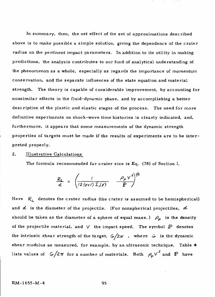
In summary, then, the net effect of the set of approximations described
above is to make possible a simple solution, giving the dependence of the crater
radius on the pertinent impact parameters. In addition to its utility in making
predictions, the analysis contributes to our fund of analytical understanding of
the phenomenon as a whole, especially as regards the importance of momentum
conservation, and the separate influences of the state equation and material
strength. The theory is capable of considerable improvement, by accounting for
nonsimilar effects in the fluid-dynamic phase, and by accomplishing a better
description of the plastic and elastic stages of the process. The need for more
definitive experiments on shock-wave time histories is clearly indicated, and,
furthermore, it appears that some measurements of the dynamic strength
properties of targets must be made if the results of experiments are to be inter-
preted properly.
2. Illustrative Calculations
The formula recommended for crater size is Eq. (78) of Section I.
2 (7+1) .T.,(y) P
Here _c denotes the crater radius (the crater is assumed to be hemispherical)
and _ is the diameter of the projectile. (For nonspherical projectiles,
should be taken as the diameter of a sphere of equal mass. ) top is the density
of the projectile material, and V the impact speed. The symbol /P denotes
the intrinsic shear strength of the target, C_/_2_" , where C_ is the dynamic
shear modulus as measured, for example, by an ultrasonic technique. Table
lists values of C__/_7_ for a number of materials. Both _pV 2 and _ have
RM- 1655-M-4 95
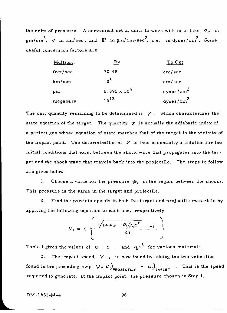
the units of pressure.
gm/cm 3, V in cm/sec, and
useful conversion factors are
Multiply:
feet/sec
km/sec
psi
megabars
A convenient set of units to work with is to take (oF, in
IP in gm/cm-sec 2, i.e., in dynes/cm 2. Some
B__y To Get
30.48 cm/sec
105 cm/sec
6. 895 x 104 dynes/cm 2
1012 dynes/cm 2
The only quantity remaining to be determined is 2" which characterizes the
state equation of the target. The quantity 2" is actually the adiabatic index of
a perfect gas whose equation of state matches that of the target in the vicinity of
the impact point. The determination of _ is thus essentially a solution for the
initial conditions that exist between the shock wave that propagates into the tar-
get and the shock wave that travels back into the projectile. The steps to follow
are given below
1. Choose a value for the pressure _! in the region between the shocks.
This pressure is the same in the target and projectile.
Z. Find the particle speeds in both the target and projectile materials by
applying the following equation to each one, respectively
Table I gives the values of GZ
$ , and _c for various materials.)
to
V , is now found by adding the two velocities3. The impact speed,
This is the speed+ be,)found in the preceding step: V= L_I)PI_OJECTIL.E TARGET
required to generate, at the impact point, the pressure chosen in Step 1.
RM-1655-M-4 96
4. The value of
found from
7" corresponding to the impact speed of Step 3 is now
-I
wherein the values used are those appropriate to the target material.
Repeating these steps at a series of values of _l then determines _'(V) ,
and this, in turn, allows one to calculate Rc/_ , using Fig. 8 for the function
(z*l) I,
RM-1655-M-4 97
CONCLUDING REMARKS
The net result of the set of approximations described above is to
make possible an extremely simple solution, giving the dependence of
crater radius on the diameter, density, and speed of the projectile, and
on the dynamic strength and state equation of the target. Both fluid-
mechanical and solid-state considerations play a role in this solution, and
their individual effects are combined by the simple expedient of terminating
the blast-wave solution at the point where the shock pressure has decayed to
the intrinsic strength of the target. The fact that the solution for the fluid-
mechanical phase is simple enough to permit such an incorporation of the
target strength is a direct consequence of the fact that a constant-energy
approximation can be used. The formula that results displays reasonable
agreement with experiment, and may be expected to improve at higher impact
speeds, where the strong-shock approximations hold over a longer portion
of the process.
Improvements in both the fluid and solid aspects of the theory described
above can be achieved, at little or no expense in simplicity of the results.
In regard to the blast-wave portion, it would appear that the most fruitful
area to explore is the development of non-similar solutions. The most
definitive test to which this part of the solution can be put is the prediction
of shock location as a function of time. The experimental evidence presently
available in this area is quite limited, and apparently lies in a transitional
regime where the shock speed has begun to decay from the blast-wave behavior
_s "_ t2/5)toward the acoustic limit (_s _of). To properly account for this
RM-1655-M-4 98
behavior, the hydrodynamic phase of the solution must be extended, so as
to incorporate the nonsimilar effects that enter by way of the low-pressure
term in the state equation. In spite of this deficiency, however, even the
presently available form of the solution gives a surprisingly accurate pre-
diction of the shock-wave location, and it may be expected to improve at
higher impact speeds.
On the solid-state side of the question, the most obvious area in need
of improvement is the rule for determining the crater size. There is no
theoretical obstacle to making the transition from blast-wave theory to a
plastic- and elastic-wave description at late time. Such an analysis would
provide a general relation between the final crater dimensions and the shock
radius at the instant of transition. Presently, these are assumed equal.
Finally, there is a need for further study of the importance of
momentum conservation, since the neglect of this consideration is crucial
in achieving the simplicity of the present solution.
Certain aspects of these theoretical findings have application to the
design and interpretation of experiments. Quite apart from its obvious use
as a practical method of estimating penetration, the implications of this
theory are that many experimental conditions must be carefully examined
if results of experiments are to be properly interpreted. In particular, it is
important to know the dynamic strength of the target material. Furthermore,
the influence of the equation of state demonstrated in these studies produces,
at high speed, a variation of crater radius with impact velocity suggestive of
"momentum scaling". The fact is that the total energy is the dominant para-
meter throughout the range of impact speeds, while reduction of the crater
RM- 1655-M-4 99
size below the value appropriate to pure "energy scaling" can be attributed
to the effect of the equation of state. Thus, extensive experiments in sub-
stances whose state equations are not well known would appear to be incapable
of determining the relative contributions from these two sources.
RM-1655-M-4 i00
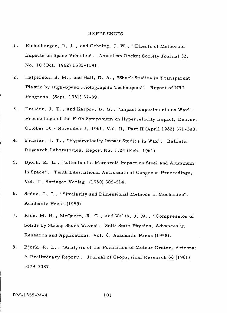
REFERENCES
1. Eichelberger, R. J., and Gehring, J. W., "Effects of Meteoroid
Impacts on Space Vehicles" American Rocket Society Journal 32,
No. 10 (Oct. 1962) 1583-1591.
2. Halperson, S. M., and Hall, D. A., "Shock Studies in Transparent
Plastic by High-Speed Photographic Techniques". Report of NRL
Progress, (Sept. 1961)37-39.
3. Frasier, J. T., and Karpov, B. G., "Impact Experiments on Wax".
Proceedings of the Fifth Symposium on Hypervelocity Impact, Denver,
October 30 - November 1, 1961, Vol. II, Part II (April 1962) 371-388.
4. Frasier, J. T. , "Hypervelocity Impact Studies in Wax". Ballistic
Research Laboratories, Report No. 1124 (Feb. 1961).
5. Bjork, R. L. , "Effects of a Meteoroid Impact on Steel and Aluminum
in Space". Tenth International Astronautical Congress Proceedings,
Vol. II, Springer Verlag (1960) 505-514.
6. Sedov, L. I. , "Similarity and Dimensional Methods in Mechanics".
Academic Press (1959).
7. Rice, M. H., McQueen, R. G., andWalsh, J. M., "Compression of
Solids by Strong Shock Waves". Solid State Physics, Advances in
Research and Applications, Vol. 6, Academic Press (1958).
8. Bjork, R. L., "Analysis of the Formation of Meteor Crater, Arizona:
A Preliminary Report". Journal of Geophysical Research 6_66(1961)
3379-3387.
RM-1655-M-4 i01
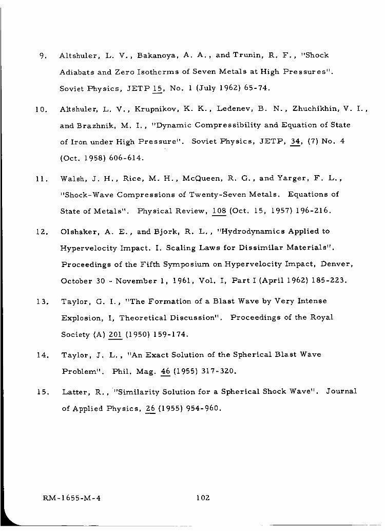
9. Altshuler, L. V., Bakanoya, A. A., andTrunin, R. F., "Shock
Adiabats and Zero Isotherms of Seven Metals at High Pressures".
Soviet Physics, JETP 15, No. 1 (July 196Z) 65-74.
i0. Altshuler, L. V.,
and Brazhnik, M.
of Iron under High Pressure".
(Oct. 1958) 606-614.
ii. Walsh, J. H., Rice, M. H., McQueen, R. G., and Yarger, F. L.,
"Shock-Wave Compressions of Twenty-Seven Metals. Equations of
State of Metals" Physical Review, 108 (Oct. 15, 1957) 196-Z16.
IZ. Olshaker, A. E., and Bjork, R. L., "Hydrodynamics Applied to
Hypervelocity Impact. I. Scaling Laws for Dissimilar Materials".
Proceedings of the Fifth Symposium on Hypervelocity Impact, Denver,
October 30 - November I, 1961, Vol. I, Part I (April 1962) 185-ZZ3.
13. Taylor, O. I., "The Formation of a Blast Wave by Very Intense
Explosion, I, Theoretical Discussion". Proceedings of the Royal
Society (A) 201 (1950) 159-174.
14. Taylor, J. L. , "An Exact Solution of the Spherical Blast Wave
Problem". Phil. Mag. 46 (1955)317-320.
15. Latter, R. , "Similarity Solution for a Spherical Shock Wave". Journal
of Applied Physics, 26 (1955) 954-960.
Krupnikov, K. K., Ledenev, B. N., Zhuchikhin, V. I.,
I. , "Dynamic Compressibility and Equation of State
Soviet Physics, JETP, 34, (7)No. 4
RM-1655-M-4 I02
16. Sakurai, A. , "On Exact Solution of the Blast Wave Problem"
J. Phys. Soc., Japan 1__00(1955} 827-828.
17. Davids, N., Huang, Y. K., and Juanzemis, W., "Some Theoretical
Models of Hypervelocity Impact" Proceedings of the Fifth Symposium
on Hypervelocity Impact, Denver, October 31 - November 1, 1961,
Vol. 1, Part I (April 196Z) 111-132.
18. Hayes, W. D., and Probstein, R. F., "Hypersonic Flow Theory".
Academic Press (1959).
19. Davids, N., andHuang, Y. K., "Shock Waves in Solid Craters".
Journal of the Aerospace Sciences 29 (1962) 550-557.
20. Herrmann, W. , and Jones, A. H. , "Survey of Hypervelocity Impact
Information". Massachusetts Institute of Technology, A.S.R.L.,
Report No. 99-1 (Sept. 1961).
21. Lake, H. R., and Todd, F. C. , "Digital Computer Solution for the
Propagation of a Spherical Shock Wave in Aluminum". Paper pre-
sented at the Oklahoma Academy of Science Meeting, December 14-15,
1961, NASA Accession Number N62-11438.
22. Kineke, J. H. , "Observations of Crater Formation in Ductile
Materials". Proceedings of the Fifth Symposium on Hypervelocity
Impact, Denver, October 30- November 1, 1961, Vol. I, Part II
(April 196Z) 339- 370.
23. Hafele, W.,
Sto swellen".
"Zur Analytischen Behandlung ebener, starker, instationarer
Zeitschrift fur Naturforschung 10a (1955) 1006.
RM-1655-M-4 103
24. Von Hoerner, S. , "Losungen der hydrodynamischen Gleichungen mit
linearen Verlauf der Gerchwindigkeit". Zeitschrift fur Naturforschung,
10a (1955) 687.
25. Zeldovich, Ya. B., "Motion of a Gas Due to a Pressure of Short
Duration (Shock)" Soviet Physics-Acoustics, American Institute of
Physics Translation 2 (1956) 25-35.
26. Adamski{, V. B., "Integration of a System of Auto simulating Equations
For the Problem of a Short Duration Shock in a Cold Gas". Soviet
Physics-Acoustics, American Institute of Physics Translation Z
(1956) I-7.
27. Zhukov, A . I. , and Kazhdan, Ya. m. , "Motion of a Gas Due to the
Effect of a Brief Impulse". Soviet Physics-Acoustics, American
Institute of Physics Translation 2 (1957) 375-381.
Z8. Mirels, H., "Hypersonic Flow Over Slender Bodies Associated with
Power Law Shocks". Advances in Applied Mechanics, Vol. VII,
Academic Press, New York (1962).
Z9. Lees, L., and Kubota, T., "Inviscid Hypersonic Flow over Blunt-
30.
Nosed Slender Bodies"
(1957) 195-202.
Franken, P., "High Energy Lasers".
Technology (Oct. 196Z).
Journal of Aeronautical Sciences 24
International Science and
RM-1655-M-4 104
if
i
/
//
31. Davison, E. H., Winslow, Jr., P. C., "Space Debris Hazard
Evaluation". NASA TN D-ll05 {Dec. 1961}.
32. Whipple, F. Z. , "The Meteoritic Risk to Space Vehicles". Vistas in
Astronautics, Vol. I, Pergamon Press (1958}.
33. Whipple, F. L. , "Particulate Contents of Space". Medical and Biological
Aspects of the Energies of Space, Edited by P. A. Campbell, Columbia
University Press (1961}.
34. Bjork, R. L., "Meteoroids Versus Space Vehicles". American Rocket
Society Paper 1200-60 (May 1960}.
35. Whipple, F. L. , "Photographic Meteor Orbits and Their Distribution in
Space". Astronomical Journal 59 (1218} 201 (July 1954}.
36. Whipple, F. L., "A Comet Model III, The Zodiacal Light". Astrophysical
Journal 121 (3) 750 (May 1955}.
37. McCrosky, R. E. , "Some Physical and Statistical Studies of Meteor
Fragmentation". PhD. Thesis Harvard University (Nov. 1955).
38. Whipple, F. L., "On Meteoroids and Penetration". 9th Annual American
Astronautical Society Meeting (Jan. 1963}.
39. Slater, J. C. , "Introduction to Chemical Physics". McGraw-Hill Book
Company, New York (1939}.
40. Eastabrook, J. N. , "Thermal Expansion of Solids at High Temperatures".
Phil. Mag. (Eighth Set.}, 2, 1421 (1957).
41. Benedek, G. B., "The Temperature of Shock Waves in Solids". Harvard
University, Cruft Lab. Tech. Rept. 316 (Jan. 1960}.
RM-1655-M-4 I05
42.
43.
44.
45.
46.
47.
48.
49.
50.
Benedek, G. B. , "Deduction of the Volume Dependence of the Cohesive
Energy of Solids from Shock-Wave Compression Measurements". Phys.
Rev. i14, 467 (1959).
Wackerle, J., "Shock-Wave Compression of Quartz" J. Appl. Phys.
33 (3) 922 (March 196Z).
Von K_rm_n, T. , and Duwez, P., "The Propagation of Plastic Deformation
in Solids". J. Appl. Phys., Vol. 21 (Oct. 1950)987-994.
Cook, R. K. , "Variation of Elastic Constants and Static Strains with
Hydrostatic Pressure: A Method for Calculation from Ultrasonic
Measurements". J. Accoustical Soc. 29(4) (1957) 445-449.
Huntington, H. S. , "The Elastic Constants of Crystals". Solid State
Physics, Vol. 7, Academic Press, Inc. (1958)213-351.
Marnaghan, F. D., "Finite Deformation of an Elastic Solid". J. Wiley (1951)
Malvern, L. E., "Plastic Wave Propagation in a Bar of Material
Exhibiting a Strain Rate Effect". Inart. Appl. Math. 8, (1951) 405-411.
Bell J. F. , "An Experimental Study of the Interrelation Between the
Theory of Dislocations in Polycrystalline Media and Finite Amplitude
Wave Propagation in Solids". Johns Hopkins Univ., Baltimore, Md. ,
Tech. Rept.
Penney, W.
of Finite Pulses in Fluids".
(I950) 46-8z.
7 (March 1961).
S. , and Pike, H. H. M. , "Shock Waves and the Propagation
Reports on Progress in Physics (13)
RM-1655-M-4 106
51. Kittel, C. , "Introduction to Solid State Physics". Second Edition,
John Wiley (1956).
52. Bridgeman, P. W. , "Studies in Large Plastic Flow and Fracture With
Special Emphasis on the Effects of Hydrostatic Pressure". McGraw-
Hill (1952).
53, Hoffman, G. A., "Whiskers". J, Metals 10 (9)591 (Sept. 1958),
54. McQueen, R. G., and Marsh, S. P., "Ultimate Yield Strength of Copper".
J. Appl. Phys. 33 (2) 654 (Feb. 1962}.
55. Eichelberger, R. J., and Gehring, J. W., "Effects of Meteoroid Impacts
on Space Vehicles". Ballistic Research Lab. Rept. No. 1155 (Dec. 1961).
56. Lazarus, D. , "The Variation of the Adiabatic Elastic Constants of KC£,
NaC_, CuZn, Cu, andAlwith Pressure to 10,000 Bars". Phys. Rev.
76 (4) 545 (August 15, 1949).
57. Zener, C., "Contributions to the Theory of Beta-Phase Alloys". Phys.
Rev. 71 (12) 846 (June 15, 1947).
58. Allison, F. E., Becket, K. R., andVitali, R., "Effects of Target
Temperature on Hypervelocity Cratering". Fourth Symposium on
Hypervelocity Impact, APGC-TR-60-39 (1) (Sept. 1960).
59. Ke, T., "Experimental Evidence of the Viscous Behavior of Grain
Boundaries in Metals". Phys. Rev. 71 (8) 533 (April 15, 1947).
60. Zener, C., "Theory of the Elasticity of Polycrystals with Viscous
Grain Boundaries" Phys. Rev. 60, 906 (1941).
RM-1655-M-4 107
61.
62.
63.
64.
65.
66.
67.
68.
White, D. W., Jr., and Burke, J. E., "The Metal Beryllium". Am.
Soc. Metals, Cleveland (1955).
Daniels, W. B., and Smith, C. S., "Pressure Derivatives of the Elastic
Constants of Copper, Silver, and Gold to I0,000 Bars" Phys. Rev.
iii (3) 713 (August I, 1958).
Schmunk, R. E. , and Smith Charles S. , "Pressure Derivatives of the
Elastic Constants of Aluminum and Magnesium". J. Phys. Chem.
Solids 9, i00-I12 (1959).
Lazarus, D., "The Variation of the Adiabatic Elastic Constants of KCZ,
NaCl, CuZn, Cu and A1 with Pressure up to i0,000 Bars". Phys. Rev.
76 (4) 545 (August 15, 1949).
McQueen, R. G., and Marsh, S. P., "Equation of State for Nineteen
Metallic Elements from Shock-Wave Measurements to Two Megabars".
J. AppI. Phys. 31 No. 7 (July 1960)1253-1269.
Jaffe, I., Beauregard, R., and Amster, A., "Determination of the
Shock Pressure Required to Initiate Detonation of an Acceptor in the
Shock Sensitivity Test". American Rocket Society Journal 3__22No. 1
(Jan. 196Z) Z2-25.
Susse, C., "Variation of the Elastic Constants of Quartz as a Function
of Pressure up to I000 Atmospheres". J. Phys. Radium 16 (April 1955)
348-349.
McSkimin, H. J., "Ultrasonic Pulse Technique for Measuring Accoustic
Losses and Velocities of Propagation in Liquids as a Function of Tempera-
ture and Hydrostatic Pressure". J. Accoustical Soc. 28 (II) (Nov. 1957)
1185.
RM-1655-M-4 108
69.
70.
Herrmann, W. , and Jones, A. H. , "Correlation of Hypervelocity
Impact Data". Proceedings of the Fifth Symposium on Hypervelocity
Impact, Denver, October 30- November l, 1961, Vol. II, Part II
(April 1962) 389-438.
Herrmann, W. , and Jones, A. H. , "Survey of Hypervelocity Impact
Information". M.I.T., ASRL Report No. 99-1 (Sept. 19611.
RM-1655-M-4 109
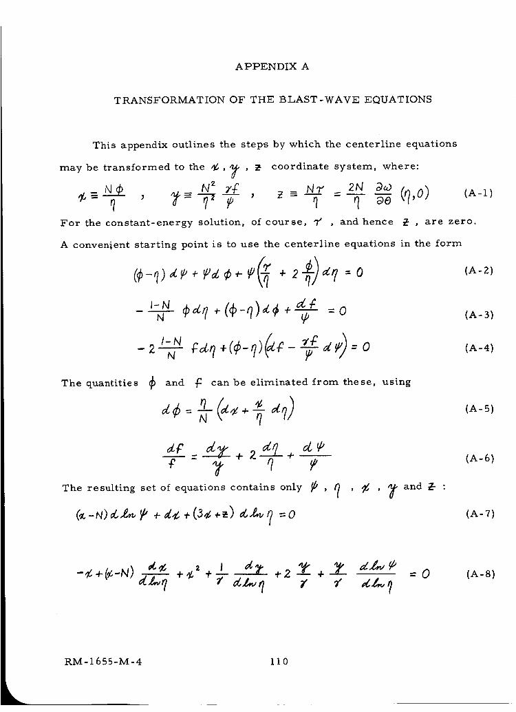
APPENDIX A
TRANSFORMATION OF THE BLAST-WAVE EQUATIONS
This appendix outlines the steps by which the centerline equations
may be transformed to the _, 7 ' _ coordinate system, where:
N_ _ N_ 2_ _ (q,o)_-_---_- , _ , _ -= =q T_ _ q aeFor the constant-energy solution, of course, 7' , and hence @ , are zero,
A convenient starting point is to use the centerline equations in the form
N
-2_ N P
The quantities and jC can be eliminated from these, using
d_
c - It qThe resulting set of equations contains only _ ,
(.-N)_ P +de +(s¢ +_) _ =o
, _- and Z- :
(A-I)
(A-Z)
(A-3)
(A-4)
(A-5)
(A-6)
(A-7)
-¢. +(¢,-N) ¢L]..,_+¢,- + I _Z_ +2 7" +-_ =0 (A-8)
RM-1655-M-4 110
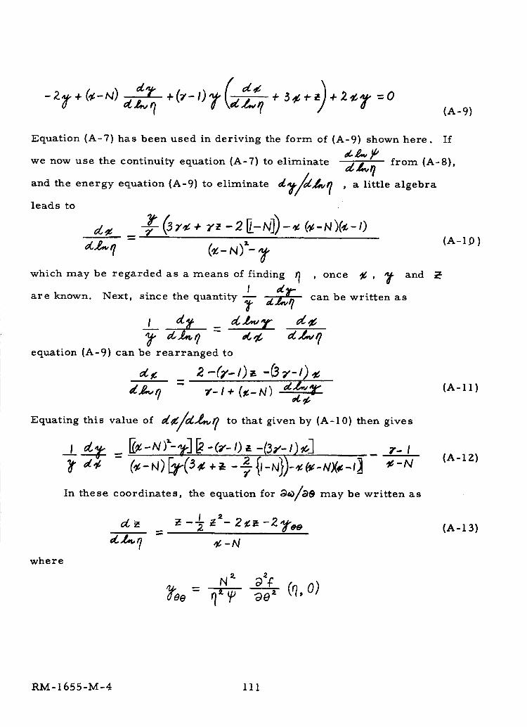
Equation (A-7) has been used in deriving the form of (A-9) shown here.
we now use the continuity equation (A=7) to eliminate
and the energy equation (A-9) to eliminate _/_,vq
leads to
(A-9)
If
_._,_ from (A-8),, a little algebra
andwhich may be regarded as a means of finding q , once _g ,
are known. Next, since the quantity I d_- can be written as
equation (A-9) can be rearranged to
,_, 2 - (_.-I) ,, - (3z- ,) ,
Equating this value of _46/6_,_ to that given by (A=10) then gives
, ,__ _:_-N)'-_-I_-_.-,). -(3_.-,)__3 _.-,
In these coordinates, the equation for D_)/D0 may be written as
= z -½ z"- 2 _ -2 _'oo
where
(A-l_))
(A=11)
(A=IZ)
(A=I3)
RM-1655-M-4 111
APPENDIX B
SIMULATION OF METEOROID IMPACT BY ENERGY RELEASE
A major conclusion reached in Part I, above, is that crater formation
is controlled chiefly by the energy of the impacting particle, its momentum
playing only a secondary role. Thus we may expect to simulate hypervelocity
impact by any experiment in which a strong shock wave is driven into a
target by the deposition of energy in any form.
It is of central importance, in considering any simulation of this type,
to be certain that the mode of energy deposition does in fact drive a strong
shock wave into thetarget. We shall return to this question below, but for
the moment we assume that this condition has been achieved, and present the
formulas that follow as a consequence.
The relation between crater radius and the amount of energy absorbed
by the target is Eq. (77):
= (r+O I , (B-1)
To specify 7" in the particle-impact case, we matched the actual conditions
behind the shock at the impact point, and found that 7' depended only on the
impact speed V We may follow the same procedure for the case of energy
deposition by some other means, except that we must now identify the
experimental parameter that fixes the shock strength, and hence 7" The
quantity that does this is the power being absorbed by the target, per unit
area in the plane of the shock. To see why this is so, consider a plane shock
wave of unit area advancing at speed _/s into a medium of undisturbed
L RM-1655-M-4
llZ
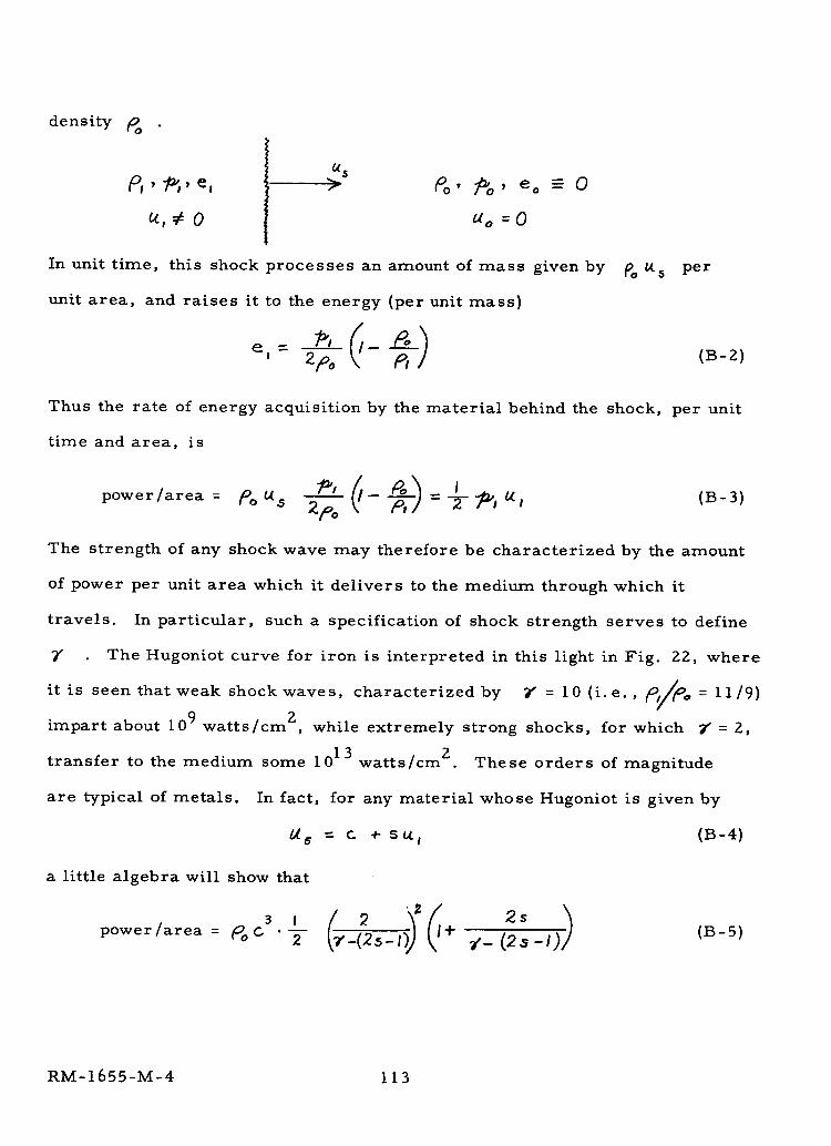
density Po
> &, eo -- o
do =0
In unit time, this shock processes an amount of mass given by
unit area, and raises it to the energy (per unit mass)
' 2po
5 per
(B-Z)
Thus the rate of energy acquisition by the material behind the shock, per unit
time and area, is
power/area = /_o Us 2/°o -- = -2- _i 6tl (B-3)
The strength of any shock wave may therefore be characterized by the amount
of power per unit area which it delivers to the medium through which it
travels. In particular, such a specification of shock strength serves to define
T The Hugoniot curve for iron is interpreted in this light in Fig. Z2, where
it is seen that weak shock waves, characterized by Y" = 1 0 (i. e. , (_t/tOo = 1 1/9)g
impart about 10 9 watts/cm z while extremely strong shocks, for which _ = Zp
transfer to the medium some 1013 watts/cm z. These orders of magnitude
are typical of metals. In fact, for any material whose Hugoniot is given by
6 = c + s_l (B-4)
a little algebra will show that
power/area = _6 '_-
2 Z 2s(B-5)
RM-1655-M-4 113
This function is shown in Fig. 23. In view of the fact that 1.0 megabar-km/sec
is equal to l0 I0 watts/cm 2, it can be seen that shock waves in the range of
interest here will generally have "power ratings" from 109 to 1013 watts/cm 2.
It is interesting, in this connection, to note that the experiments reported by
Altshuler et al9 achieved shock waves of strength equivalent to 4 x 1 011 watts/cm 2
If we consider the deposition of a total energy E over an area A of the
target surface in a time _ , it is clear that _ will be a function only of E/A_-
Thus the craters formed, according to Eq. (B-l), will depend on the two para-
meters E and _T _ Fig. 24 shows the craters predicted by Eq. (B-l) for
deposition of energy in iron targets, at various values of E and AT _ . Over-
laid as dotted lines are analogous predictions for the craters formed by impact
of iron projectiles of various sizes, striking at various speeds. As noted above,
there is a one-to-one correspondence between impact speed and the power
density at the impact point, and both of these are shown on the abscissa scale
of this figure. The point to be noted is that any experimental technique capable
of driving shock waves of strength greater than i0 llwatts/cm2 can simulate
impact conditions which are presently beyond the capability of conventional
projection techniques. One energy source that immediately suggests itself for
such an application is the laser. By focussing the beam from such a device,
power densities of I013 watts/cm 2, delivered in less than a microsecond, can
be achieved (30) with existing equipment. The fact that the maximum output of
these devices is currently being improved at such a rapid rate indicates that
simulation by a laser beam is a promising experimental technique.
The calculations presented in Fig. 24 to illustrate the simulation
possibilities start from the hypothesis that the energy absorption takes place
RM-1655-M-4 I14
by means of a blast wave mechanism. Particularly in the case of electro-
magnetic energy deposition, this assumption needs careful scrutiny. There
would appear to be little doubt that is is the correct mechanism when the
rate of energy input is sufficiently high. Certainly, the different phenomena
brought into play, at one extreme, by striking a match and, at the other,
by detonating a nuclear bomb, provide evidence that the mechanism of energy
absorption changes, at some point, from one of linear heat conduction to the
nonlinear shock-wave mechanism. Exactly where such a transition will
occur in solid media is not presently known, although it is presumably
amenable to theoretical analysis. The conclusions reached above are based
on the assumption that a shock wave will be the correct mechanism when-
ever the incident power density exceeds l0 ll watts/cm 2
RM-1655-M-4 115
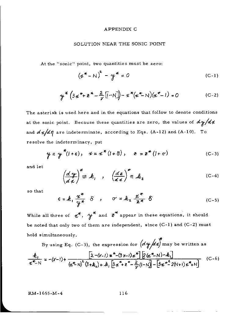
APPENDIX C
SOLUTION NEAR THE SONIC POINT
At the "sonic" point, two quantities must be zero:
_ 0 (C-l)
The asterisk is used here and in the equations that follow to denote conditions
at the sonic point. Because these quantities are zero, the values of _/_
and _/_ are indeterminate, according to Eqs. (A-I2) and (A-10). To
resolve the indeterminacy, put
and let
(C-4)
so that
E=_, _-_ _ , o_=_, _-_ 6
While all three of _, ?_ and _ appear in these equations,
be noted that only two of them are independent,
(c-5)
it should
since (C-l) and (C-2) must
hold simultaneously.
By using Eq. (C-3), the expression for may be written as
RM-1655-M-4 116
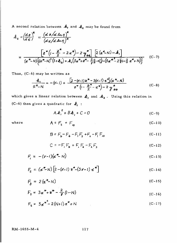
A second relation between "_l and _ may be found from
/__,,.__ _ (_,/_)"_: =t_-_/ - (d_Id.z..q),+
(c-7)
Thus, (C-6) may be written as
4, - (r-O+ _-(','-O_-"-_(,'-O,_I(_'-N)(c-8)
which gives a linear relation between "_l
(C-6) then gives a quadratic for _1 :
2
A,_, + B.,A_+ C = 0
and _2" Using this relation in
(C-9)
where A = _ #" Flo (C-lO)
B: %-r,-_,5 +C-_ F,<> (C-ll)
C ...
c ---C% + ;, _-C;_
-(,,-0(_ N)
(c-lz)
(c-13)
--(_'-N)_-(v_i)__(3__i)_*] (C-14)
F5= :_% _* ;_- -#-(I--N)
(c-is)
(c-16)
(c-17)
RlVl- 1655-M-4 117
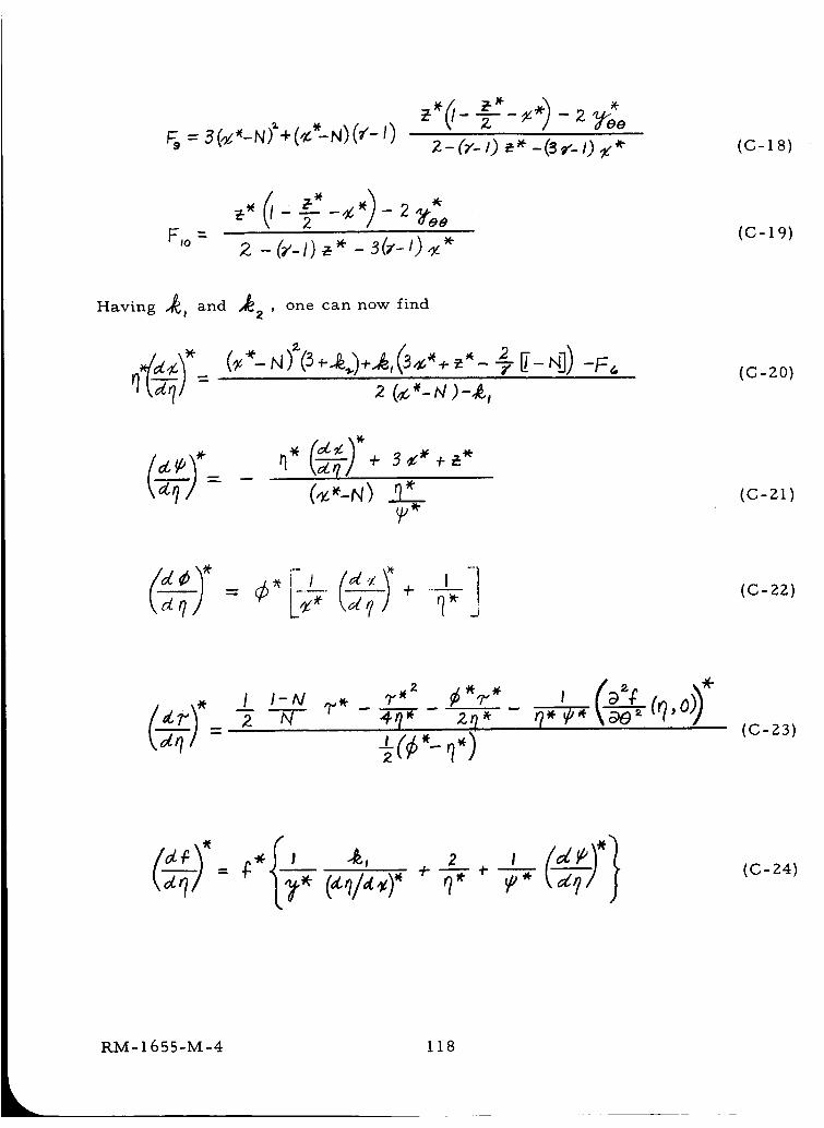
;, = s(_,_m_+(ctN)(¢-i) 2- (_'-I) _< -@¢_ 0 ,'* (c-18)
FIO _
_* ¢ * - 2 "gee2
z -(_'-O_'+-s(,'-O_ '+(C-19)
Having _, and "_2' one can now find
(,_.,'_,q)"(3+..<.)+,,(3_,,+.,,---e"__-,])-F,.2 (_,'-_/)-&,
(¢-2o)
k7£1 + s +(,_"-N) 22._ (C-21)
L-+7t77-_;+ _., (C-22)
I I-IV ,.Vv¢ ?.,2 _[,p.,
z N _r/_ ,zr/*
-_(¢_'-_)'7*_P \ae" ('7'°
(C-23)
'" ;. I4- --
_v*(C-24)
RM-1655-M-4 118
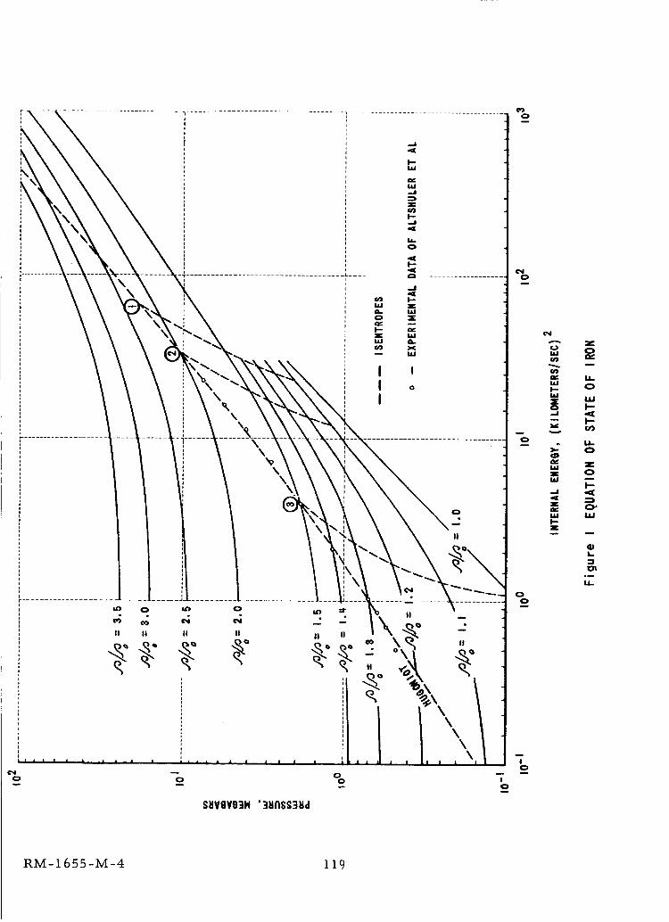
\
\
\l \
\ \\_\
\\
0
I!
0
_ 0 _ 0
II II U II
Ll • I I I
0
SHVGVO]H '3HNSS3Hd
0
_" LL.U.II-- 0
31C LU
o I--
-- I--¢fj
o
>'- 0
uJ _l_z 0
I--
-J .,_
.4E
ac ¢_'
ug uJI-z
L
°_
1.1_
om
m
II
\\\\
l l l I l
I0
RM-1655-M-4 i 19
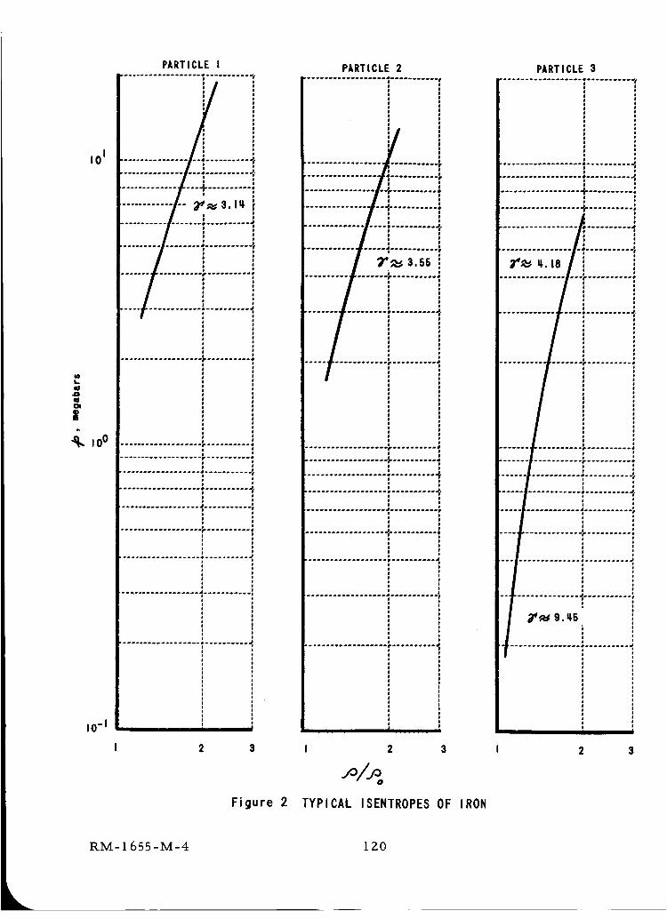
PARTICLE I.. ....... . ......... e. ........ ..
I
iI01 .................. i ...........
----.-;--.........;;2;;;:.
......
m,,Q
m
.q. =oo ...............................
.......... . ............. o .....
...... °....... ........ .°. .... =
........... °-------' ........... 1
eo
1d
o
1m
oo
........ . .................... d
I0 -I , i,,, , !
3I 2
Figure 2
PARTICLE 2
• ..°°° ..... o..o..., .......°°..,
....... ° ..... .°.°.......°°..°.,
!..... °....oo............o°.°.
........ °° ................. ...°
.... .a.°.m...°.... o.°...Qo...
........ ..e...°°.._...°..o. ....
| I
I 2 3
jO/jOo
TYPICAL ISENTROPES OF IRON
PARTICLE 3. ........ . ..... .... o...... ....
.... ° .......... . ...... ....°..
I
........... . .... °. °°....o..°.
Y_ n8
z it ,o 1
! ;o ;
1
........... o ........... _
.......
..............iii.........o 6o ae dI J
: ,j mo o
: i
i i
I/
I I
2 3
RM-I 655-M-4 120
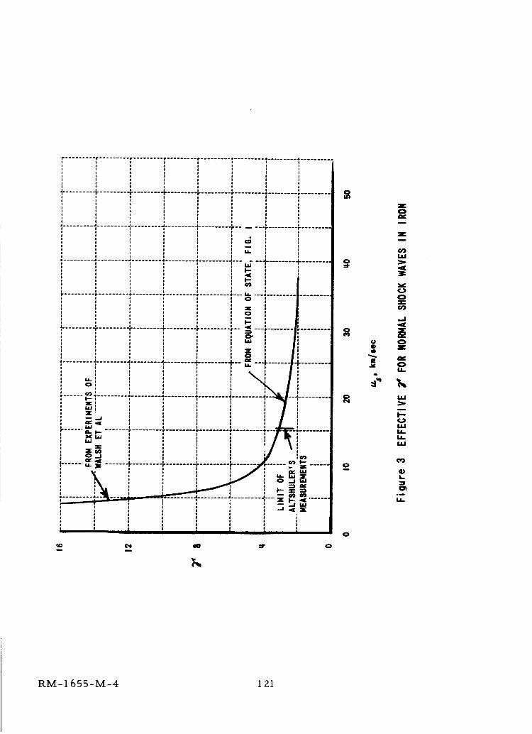
..........................................................................r • • r r * 4 4
_e........ + ........ + ........ + ................... , .............................
Z
t i.
F --+........'+.........
.......... ! ................... "......... -I-........ +--i!
m m0
0o}
0!
0
0t)Q
E
Z0
Zu
U)UJ
0Z=U'J
..J
.,_
t50Z
0U.
111
NI--
U..
4)k.3
RM-I 655-M-4 121
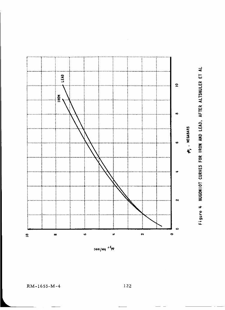
................................................................• r • • * 4 ......... • ......... * .........
i /
;.......... f" ............................. r ......... r ......... r .........
.J
0 oO _D =r o
o
oO
_D
0
<
0
k-0
z0
t,.
:3
0_
_s/_ '_
RM-1655-M-4 122
.......................................................................i.......!.........i.........• ......... • ......... .*......... A......... J ......... J ......... J ..................................., , o | o , , * l ,
o , , , , o , i , o
f ......... • ......... r ......... r--* ...... • ......... * ......... * ......... * ........ * ......... 8 ..........
, i o * o ,
• o , , • ,
v
...........r ' ' _......... "......... _......... "........ F......... ,".........• * *
t J ja a
.......... _ ............................. J ......... -,'.................... I-...... + ......... :...........
..!.........i..........
r ......... r ......... r ..... _ ....... r ......... t ......... • ......... tDot........ • ......... _ .........i * , , , * J ,E , ,
o , , , * l , * oo , , o o * J , , ,
• ........ j. .. j j , i * _ , ,i -- l ...... i ......... i .......... _ ......... r ......... r ....... r ......... r ......... r .........
• * , l * * t * . l
• * i * * i * * , 0
. * , , * i J l , ,, , * i I ! J g * I• * , i l l f i , ,
• ......... • ......... . ......... . ......... • ......... J ......... J ........ J ......... _ ......... J ..........
, , , * * t , a
• , l , * J ' , *, , , l l # , * i
, o l , i * l * ,i , o , * l * ,, , , , l i I l * ,, , , , * i o , g• o i , * l o , ,
......... • ......... r ......... r ......... r ......... r ........ • ......... • ......... t ......... r .........
, , _ ; a * a ! a t
• 0 a , 0 * * * * 0, , , , , o * * , ,, l , l l l # * l ,• * l * , o i * * ci j j j i l i , , i,......... ,- ........ ,......... ,.......... r ......... r ........ r ......... r ......... r ......... r .........
i , , i i i * i i ii i * * f * * i i
I ! I I t I | * I I
, , l * , i I l , i
, I I * I I I I I I
• ......... a ......... 4 ......... • ................ • .................. J ......... J ......... J ..........i i *• , i Il , i l, j I• , , pi p *
r * 4 4 .p ..................................... . ......................................................
o
' I II , ' i I
Z,,,
d-
zoQ_I
¢.)
I--
_D
S LLI_0 .._
I-"r_
o. ,.n
i-¢.) _'*
_o <[ 0
--- N
I--
0
G)L
C_
oI
RM-1655-M-4 123
2.0
1.6
1.2
.8
.........i.............ii........i.........i.........i.........i..........................I o I
''' '-_'i i ! i......... " ......... " ......... _........ " ......... " ........... _........ _......... I ......... ;* i I * i i * o
, N= 0.30: , ,: ' ' I : o ' : , '* o • o! I I o * i i ° o, I I , I , ,
I * l lo I i I _, o o I,
I o t t t I *I I I * I
I ! I I I o, i ; I I * o *, o , o I I * io o o I I *
, I o ** o I I *L , I , , , ,
............................. iiii-! iiiiiiiiiiiiii ii i i ! i :'io
' I ' I ' ' ,, * , o i o, * , l o, i * I l ° *° ' , ' I : ,I I Il I I I * * I
' L ' ' ' " ,......... _ ........................... • ......... _ ....... _ .................. o
o I I I 4 I oI I s I °
I I I* I l , I o
' I ' I , I I
, o *I I I o ° * _ , *
I I I I I I I I! i = i ! ! ! i i
I "I I _ o ° o
, I , . • , , I ,I ' ' : ', I ' -- , ,* i /- [tT" "CJ )1, • _ _ ; i
• ' i] i ii................. i. ..................
i i : i : i ! i iI a I , *
I I I I I , :* t ° *
I I ' '
.92 .9q .96 .98 I .00
1.0
.8
.6
.q
.2
Figure 6 ATTEMPTED SPHERICALLY-SYMMETRIC SOLUTION, N = 0.30
RM- 1655-M-4 1 Z4
1.0
,8
_ocx.q
.2
.........T........Y.........[.........i.........i.........i.........i.........7.........i !.........i.........i.........i.........i.........i........i........i........i...........! : I : : 1
........*.........?........_.........4.........i.........!.........i.........:......... i
..........:.........i.........,.........; ........_........, ........, ........+...... ,. ii i i ! i i ! [7_ i
.........!.........÷.........".........L........i.........i.........i........_/-----_---i
................_ _:..........;. : ' i .....
-i ......... i
Y
i .....I.........I.......i........f........i.........i........!........_.........i4---..i........i.........i........i........i........I.........i........i........1......./....._ ..
i I ' ; _ i iI,........_.........,........,_........,........t.........t........_......I
tH t, t i i ......................' _]i _ ...... ti......... !i........ "_J................_........]".................I........_...... ,-........_.........i..... ._
l • , _ li'l t i i t ir I -.* ........, _;P':......._--.i .......!i _ ! ,j,,"_ i ! i i
00 .2 .q' .6 .8 1.0 0 .2 ._ .IS .8
Figure 7a DISTRIBUTION OF DENSITY, PARTICLE VELOCITY, AND PRESSURE
CONSTANT-ENERGY, SPHERI CALLY-SYMMETRI C BLAST WAVES
0 .2 ,q ,ll • 8 J.O
...........................[........].........,.........i.........I........_..................J: i i I ! J
' 'li.........................................i ill , , i,i.........t........-_.......,.........i.......
........_........_........_-........t.........t........1.......i........_/ .......iI i t ! / / / ,.i/_........!........I........f........l.........i........i........_--i- .......i: . ° ..........i........_........_........i.........i........_......._.....I.......!......
i ! :........i........i........l-........,....... i ., i i: : i l ! l .........
f ! i ! i .........il........_" ....i• ; i r i i • ; ;
IoO
RM-1655-M-4 125
1,0
,8
,6.¢,
"_ SHOCK
I}
,2
i i i i _ i i ! /",.:. . ..;......... ; ......... l ......... i ......... _,......... :......... :......... :....... ',
' i i _ !
J, .:_.....:_..-.,........J,.........i.........',........._.........i.
i { i {,/ _
J........! ..... i . i......."l--.---{.----.---"........_........."........': _ " {/,{' ili i i i i I , i {
.,........, .........;.........i........._........., .........i--/.-..i........-i.........i
i i i {
.........i.........i.........i.........i..................................... ii i i _ _ i i i i i
0 .2 .q .6 .8 I.O
1,0
.8
.6
I_ SHOCK.q
.2
..........................................'......... '.oI........! _ i i.........i.........i.........!........i.........i......./........ _......... ; ......... :......... :......... _..... ! l , i
, , , , , i ! i i i { i i i i
i l i '/I
1I
........i.........i._.......i..................!................................i+, ._ ........i.........i.........i.........i.........i.........!.........i.........i7! .........]_ ! i i ! ! i i i :
i -i ......, i ........i................,.........,.........,.................,i ..ocK L i { j i........ •i-........ .i,........ 4........._---7-........ +...... ,_......... ;......... "......... r......... !
i i _ _ i I i l i _ . _ _ _ ............:..................._.........i
......._.......,2" i i_........, ........._.........il........._.........i.........i.........i.........i
0 .2 .q .6 .6 1.0 0 .2 .it .ll .8 I.O
Figure 7b DISTRIBUTION OF DENSITY, PARTICLE VELOCITY, AND PRESSURE
CONSTANT-ENERGY, SPHERICALLY-SYMMETRIC BLAST WAVES
RM-1655-M-4 126
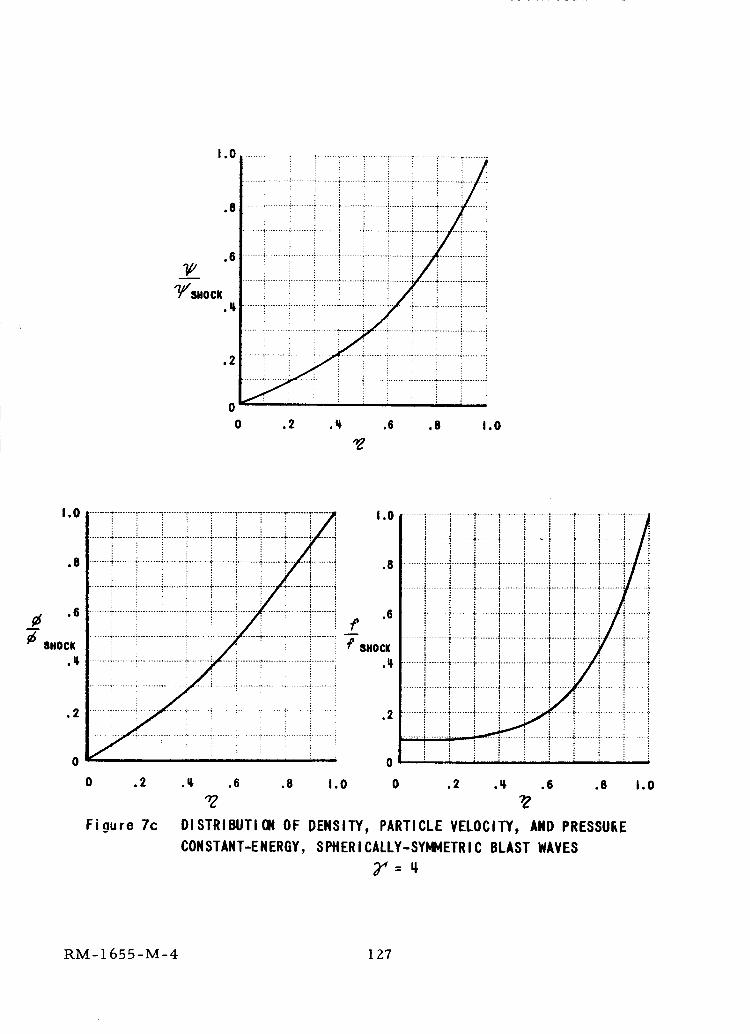
1.0
.8
.6
"////SHOCK.4
.2
0
0
........!......i.......!................!.............T........!.........!.........i....... _ ....... _........ _...... _-........ ;....... _ ....... _......... _-........ i....... !
.2 ,q. ,6 .8 1,0
1,0
.8
_. .6
SHOCK
.2
........+........._.................. :.........]........._........."........T........T....... , I. 0
........ ._........ _......... _......... _........ _......... _......... _........ _......... +i....... '_
........._................._........._........_........._.........'_........+...... _.........i ,8! ! _ i i _ i : i i
........ _-........ +......... +.......... _........ +......... !......... _...... + ........ t ........
........ _+........ . ......... +......... +-....... _......... !......................... _.......... i .6
7"........_........._.........:........_..............'......+.................._.........' -'P"8HOCI(
........_........._........_........+........_......_........._.................._.........: •I_
.2
0
i t ! i _ ii i + i !
........".........+........+,........+..........+.........i........
......i........._........I........t................._........: - : : i
........_.........i........+........'+.................+.......ii i ! :
......._...............;$........+.................._........
: = i ! _ i
.... _........ ' ........ ,I+........ , ........ _ ....... -t ........ ,: 1' : : ; :
i i ! i i........._.........+........+-.......+.........i.......".........
i : + :
+ -+, ..... t ½ -f....... t ........ , + ........
........ i........+i-........+.........i....... _............
0 .2
Figure 7c
........i........!.......i
........ ;......... : .......
........i.--+.--i.........
.........i.......i.........
......._........i........
......... _........ ; . +:
.=$ .6 .8 1.0 0 .2 .q .6 .8
"g _Z
DISTRIBUTION OF DENSITY, PARTICLE VELOCITY, AND PRESSURE
CONSTANT-ENERGY, SPHERICALLY-SYMI4ETRIC BLAST WAVES
_'=;
i
1.0
RM-1655-M-4 127
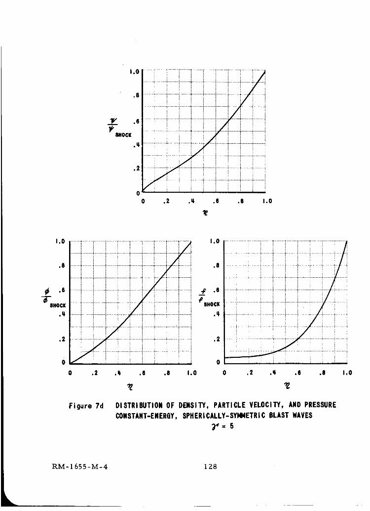
I.O
.8
'W/ .6
8HOCK
.q.
.2
iiii!iiii_
I i I I
0 .2 ._ .6 .8 1.0
t.O
.8
81lOCK
.li
.2
::i:::!::::i o........ •_........ _......... i ......... _........ _ ........ i ......... .:...... _-........ _-........ i
........._........!.........!........._........_........._.......:........_........._.........i _ .6
........ ._......... i......... i ........ _ ........ _....... :......... ._........ ._......... i ......... _ _0 8HOCK
,2
0
0 .2 ._ .iS .8 1.0
I0 .2 ,ll ,_ .8 I.O
_Z
Fi 9ure 7d DISTRIBUTION OF DENSITY, PARTICLE VELOCITY, AND PRESSURE
CONSTANT-ENERGY,SPHERICALLY-SYMMETRICBLAST WAVES
3,,=5
RM-1655-M-4 1Z8
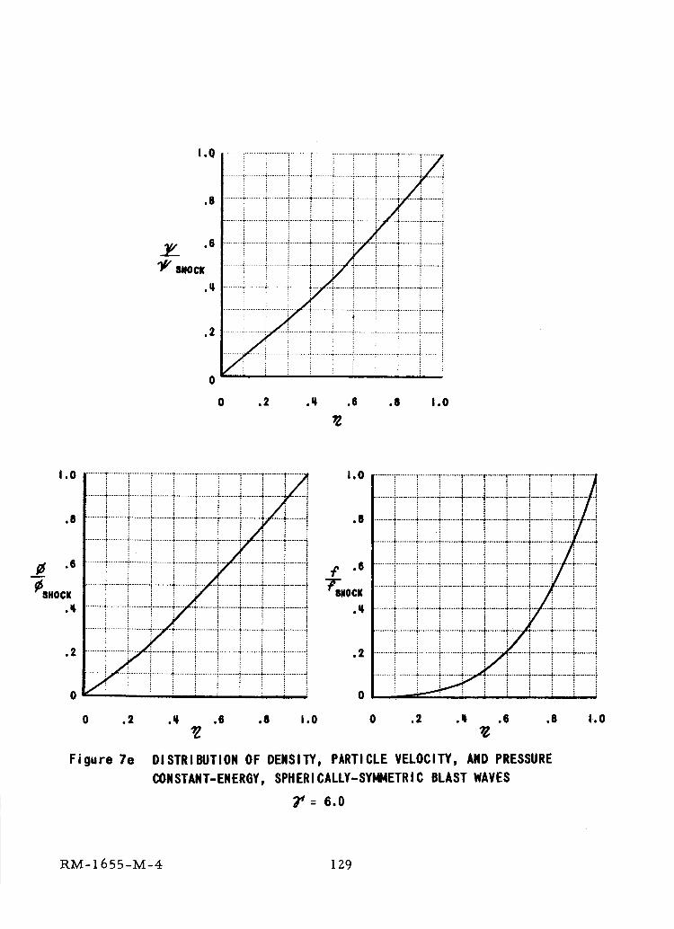
1.0
,8
.q
.2
7 i........!.........i.........i........!........i............,.........i.........._........*........-:..... i........._........*.......-:.........i
! ! : ! : i, i i i !
i i i J i
0 .2 ._ .6 .8 1.0
1.0
.8
j_ .8
_$HOCK
.q.
,2
1.0........ .T ........ ",......... : ................. ." ........ I ......... r ......... r ........ t .......
........ t ........ "......... .:................. r ........ '.'-.......4.......4 ........ ' ......! i _ ! ! i /. J
! i _ ! ! i i J !;.'../..._.4....... t- ........ .b ........ ; ................. 4- ........ _- ........ _ ........
i i ! i i I : i !........ i......... "......... i........ -,........ a-........ .:........ 4..... 4........ ;-........
....... 4-........ _................. 4......... "......... "...... .:........ .i-........ _......... :i i i i i _ i i i
........,;........i.........i........+--------___..--.}
........t........•.........}..........,..... t ........_........-r........._........!.......
__ i !Tii i!!iiii!! i iiiil iiiii i....... _......... +......... _..... -;-........ {......... _........ -_........ _-........ 4......... ÷
......._........._...... _........*........4........._........_........a-........i.........i
.8
.q
.2
0 0
i i _ v : i : : : :.................i........._........!........I.......r ...._........_......"_....
: : : _ : : i _ :/ i......._........_........-i.,:........_........_........_.........i........._........7--.;: : : : : : _ : :
........4-........i-........i-........4-........4-........4-.........i.-........i................. ._
........ i......... i......... "......... _.........".'......... i......... 4-.......4-..... 4-........
........!.........!.........i.........i........_.........i.........i.........: ........i.........i
........, ........, ........, ........, ........, ........s........i.......;........4.........ii ! _ _ i ! i i i i
.....................:........._........._........_......
........i.........i.........i.........i.........i................,,'........._........_........
........ ,;........ -_........ -i......... .i............. .;,........ ._...... -_........ : .........:
0 .2 .q .6 ,8 1.0 0 .2 .q .6 .8 1.0
Figure 7e DISTRIBUTIOH OF DENSITY, PARTICLE VELOCITY, AIID PRESSURE
CONSTANT-ENERGY, SPRERICALLY-SYI44ETRIC BLAST WAVES
g' : 6.0
RM-1655-M-4 129
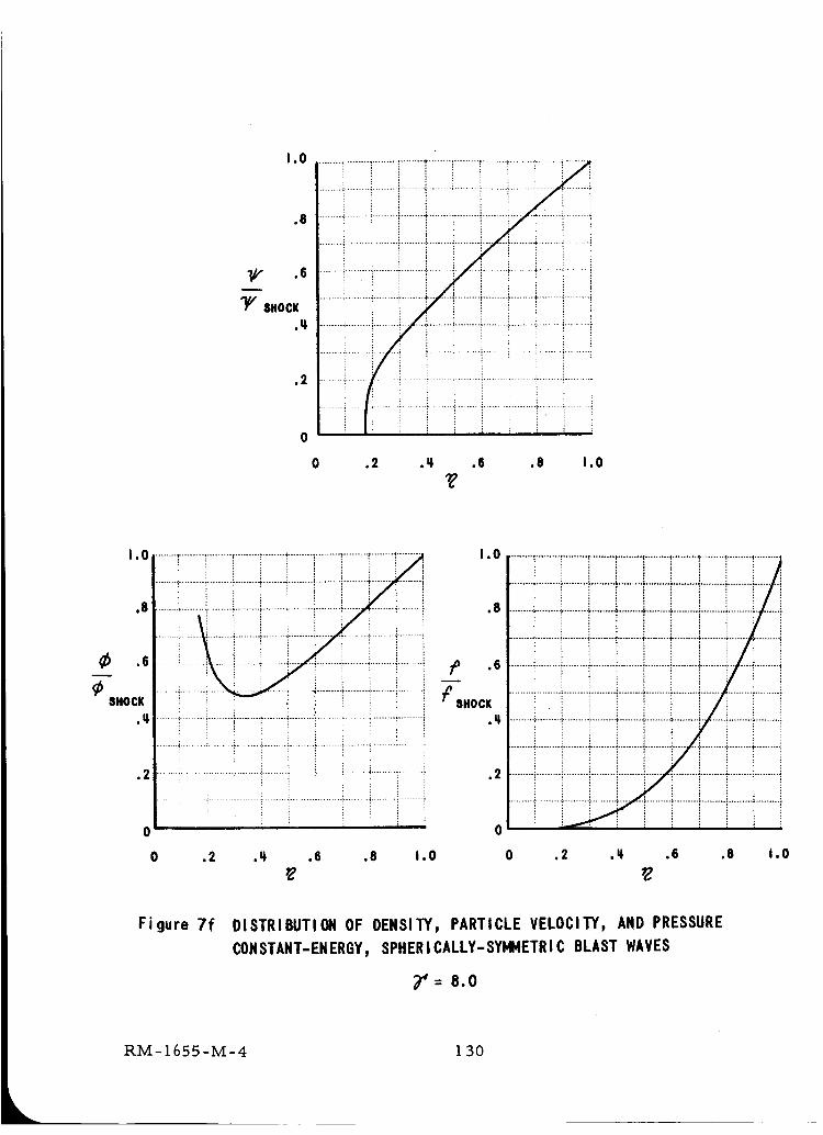
t,O
.8
•"{/,," .6
"_ SHOCK
.Ll
.2
i!iii!_!i_
0 .2 ._ .6 .8 1.0
I 0,-.......-_............................;............................;.........................."_, 1.0 ........,..................;.........,.........,........._..........-......._-..................
........+........:........._........._........•.........i........._........_".......!........_ i i ! i i i i i i i........_........._.........i.........i.........!.........!.........!.........".'.........".......
,e ......._........i.........i........._........_...... i........._.......:........_........i ,S ........_........._........._........._........._.........•.........•........._.........i.......
........ ........ ;......... _......... !...... _......... _....... _..... _....... _......... _ ........ ._......... _......... ,;......... _ ........ ,;-........ .,;-......... ';......... _................. i
SHOCKI i _ ! ' _ i i i :: - _.ocx•,_........i.......i.........i.........i........i.........i...............i.........i.........; .,_ ........_........._........_,........._........_.........:.........._......_..........;.........
O' 0
0 .2 ._ .6 .8 i.O 0 .2 .q_ .6 .8 I.O
Figure 7f DISTRIBUTION OF DENSITY, PARTICLE VELOCITY, AND PRESSURE
CONSTANT-ENERGY, SPHERICALLY-SYI@IETRIC BLAST WAVES
_'= 8.0
RM-1655-M-4 130
1.0
.8
.6
y+SHOCK
.2
0 .2 .P, .6 .8 1.0
1.2
1.0
_) .6
SHOCK
: i
.......4..... ; ............................;...............i........_.........f _
•2 .......... _ .......i......!...... !.......! .... _......... ,
0
0 .2
Figure 7g
i.0
.8
.6
SHOCK
.2
0
.q .6 .8 1.0 0 .2 .q .6
DISTRIBUTION OF DENSITY, PARTICLE VELOCITY, AND PRESSURE
CONSTANT-ENERGY, SPItERICALLY-SYMMETRI C BLAST WAVES
........i.........i.........i.........i.........i.........!.........i.........i.........i.......!
........ _......... L........ $ ......... '_........ ¢ ......... '_......... ; ......... _........ i ....... "
i.i
.8 1.0
_': 10
RM-1655-M-4 i 3|
I.O
.8
"I_ .6
_s.ocx.q
.2
........i.........i........i.........i.........i........i........i.........i.........i.......i
........!........i....i ! i _ 5 i i i i
"lilil iili i i i i : i : :
1 [ 1 i : Ei i ! i i i i :
0 .2 .q .6 .8 1.0
i....................... ......... _ ....... :......... ;......... ,....... _..................
i _I. _ .................... '*............ i........ ' ................. _.........' ........ '*
1,2
_6 1.0
_'$HOCK, 8
.6
.2
........i.........i.......' ........_.........i........i........_.........i.........i .........
........_.........i.........,_......_........._.........:-........-_........i........._.........
........ !......... _......... _........ _,......... "......... !......... ',"........ I......... !.........
,.o........i.........i.........i........i........i.........i_ii........_........i_........_........._..................÷........i........._.........i ........_.........,:....... !• 8 _ ! i ,_._._...,,:../:
........!.........,.................!.........i.........i ........_.........i.........i........._ ........i.........i .........i ........-i-........i.........i.........i........_--_--- .....i........_.........i .........i ........_..........'.........i.........i........._......._.........
........._........_.........._........i........._.........i........!........._........._........_ ,/, ,6 '- -'./- "i -
........._........._........_........!........._........._........_........._.........'_........_ r_-SHOCK ........i........._.........i ........_-........_........._........._._iiii!...... _........i..........................._........_.................._........_..........................._........_ .q ........_........._.................._........_........._........., ........_........_.........J i i i i i j i
........_-........i.........i.........i ........-_........;...... i.........!........_-.........:.........!........_........_.........i.........i........_-........j.........i.........}........_ '_',, T-7
,-------_........_-.......i.........._........_........i.........i........._........_........i • 2 ........i........_........._iiii_i.........i.........i....._........i.........!........_........i....... _........ _......... _....... ,........ _........ i- ........ i......... i ........ 4 ...............-_........_........."........."........-_........_.........i........._........-_........
I i : i ; _ : i ; _ 0 i i _ ': i i
0 .2 .q .6 .8 1.0 0 .2 .q ,6 .8 1.0
Figure 7h DISTRIBUTION OF DENSITY, PARTICLE VELOCITY, AND PRESSURE
CONSTANT-ENERGY, SPHERICALLY-SYMMETRIC BLAST WAVES
7' : 12
RM- 1655-M-4 1 32
1,6
1.2
1.0
SHOCK
.8
.6
.q
,2
0
1.0
_/. .6
11,"SHOCK
........i........i.........i........i........i......T........!........_........i..............!........i.........i........_.........:.........i .......i ............... i.........i
.............................i]i.........!..........:...... , ........i.........i........._........* ........_.........i
........ • ......... • .............. + ........ •............................ + ........ 4 ......... :
i
"'.........................i.......................................................!.........i.......................... _........ + ........ _........................... * ........ i......... i
J I I i
0 .2 .q .6 .8 1.0
9
/ i ! iI , i i i _ ! it'------_ ........ +-------_-----4 ........ + .......................... ,;........ _.........
.......*.........:........_........ i.........*........._........÷........_.........+.'........:.,' ,:
....... iii " '" _ i ! _ ' __........ _......... !...... i ........ ; ........ !......... _....... ! ..... 't,..... i
....... 4i i........ _......... i ....... _........ _ ........ "......... i ........ 4 ........ _ ........
.......* ........i.........i........_ ......_........!........_........_........_.........
....... +,........ "......... "........ _ ...... _......... "......... _........ +..... _......... i
I • 0 ! ....... _ ........ _,...... _,...... '_........ !......... !........ _ ........ r ........ ;....... "_lI I i i i _ _.
! ........;........_........+......._........!........_........_--_---._........i----J--iI • ' ' /i! i i i , i i i it.....i• 8 ....... i ........ 4 ........ 4 ...... 4- ........ _ ........ ÷...... 4 ........ _ .......
.... : ' ! i ; _ _ _ ; :.............................................,-................_........-_........_-........i i......-:........4.......-_.......,-.....1........_.......,.......,-.--_i........iI ! | _ i ! !/i iI i i ! _ l " i/ ! i
................................... I........,-'------_.....,_---+.....÷.....4....-_.._,----_.......'s ,OCKI i I _ i i i
....................................._ ..-_........".........i . q _---÷ ......_......t------_....._..... 4..-.-.#.......i----i ........_.to"-- ) ! i , ) !/il-----." ....... _ ........ - ........ i ......... :........ L_--.-..._......... !......... i ......
.2 .......i........_........_..........................................
! ! _ _ i ;'..! ,! ii iI ii ; : , i : 0 i i
0 .2 .q .6 .8 1.0 0 .2 .# .6 .8 1.0
Figure 7i DISTRIBUTION OF DENSITY, PARTICLE VELOCITY, AND PRESSURE
CONSTANT-ENERGY,SPHERICALLY-SYHNETRICBLAST WAVES
_r': 16
RM-1655-M-4 133
1.6
i,2
I,O
,8
'$HOCK
.6
,It
.2
_0
.........T........i.......................................
........ t ........
I
........ ! .........
........ I .........
......... i ........
i...............!......'i/Io"....... _..... _ .... :
0 .2 .q
1.0
.8
.6
I_$HOCK
,q.
,2
--.i ........_ F _ .....i.........I _ ,_ , _ ;_ll i i i i ! ,I ,, : = i i :
..... ,........ L.- f_--i- ..... !..... i
E ; i ! i _ ii i _ i i ; i i I i
...... i................. .I........................ i.................i.........i: L = : i i
....... ;..... _--' i ;- "" i -- _...... _......... i ...... {.....
i i 1 ', i 1.... ! '-!1 - t ............... f .... _..........
: i t [
! i i : i- - _......... ,_ - _.... i ......... _............
! = ! i i : ; i : i
! i i i i i _ i i :
o .2 .; .6 .s I.o
T ........ "
_)$HOCK
l : I l _
• 6 .8 1,0
1,0
........ _-........ _-........$ ......... _........÷......... ,.......... ............................
! i i ! i !........ ;......... _......... .,'......... _-........ _......... _-........ .,'-........ ._........ ', ........ i
........s........._..........;..........;.........i........._.........i.........: ........i.........i
........_......... .'......... _.........%........ ._......... _......... _....... •......... _........
......... _......... _......... ..'......... _......... _-........ _-..... _-........ -i.......... i..........
.........i.........!.........!........._.........!....... ,.........,:........._.........,;........._.
........._........-_........._.........i..... _.........i........._........._.........;.........i
........";........i....................!.........!.........i.........i.........'_.........i.........i
0 ,2 ._ .6 .8 1.0
Figure 7j DISTRIBUTION OF DENSITY, PARTICLE VELOCITY, AND PRESSURE
CONSTANT-ENERGY, SPHERICALLY-SYMMETRIC BLAST WAVES
7'= 20
RM-1655-M-4 i 34
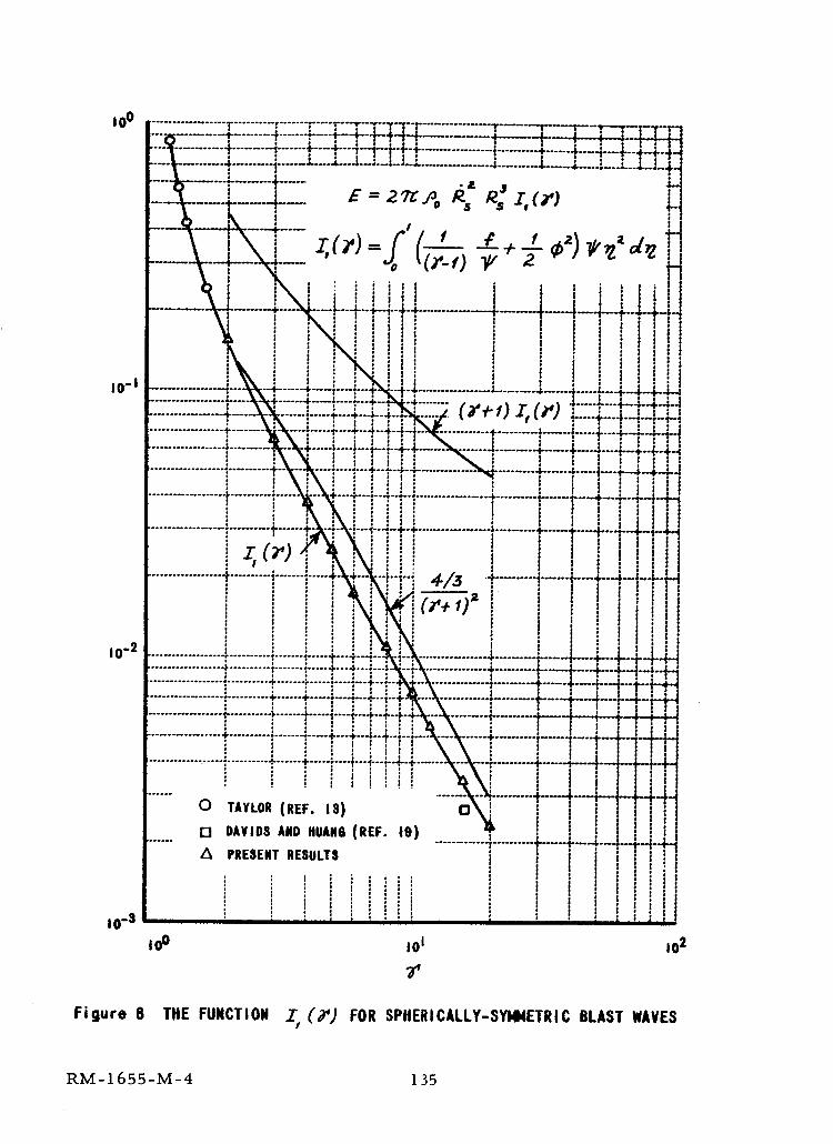
iOo
i0,-I
!
a
I0"" ................. _.......... ;....... i .....l ;
;.................. • .......... 4- ....... Fi '
4- ...... 4.' i
........... _...... "i"..... l.....! !
........... o....... ; ..... .i....+...
i iiio TAYLOR(REF. IS)r"! DAVIDSAND HUANO(REF. 10)
A PRESENTRESULTS
: !
10-3
l
!i!
I0 0 i01 102
Figure 6 THE FUNCTION Z (9 _) FOR SPHERICALLY-SYMMETRIC BLAST WAVES
RM-1655-M-4 135
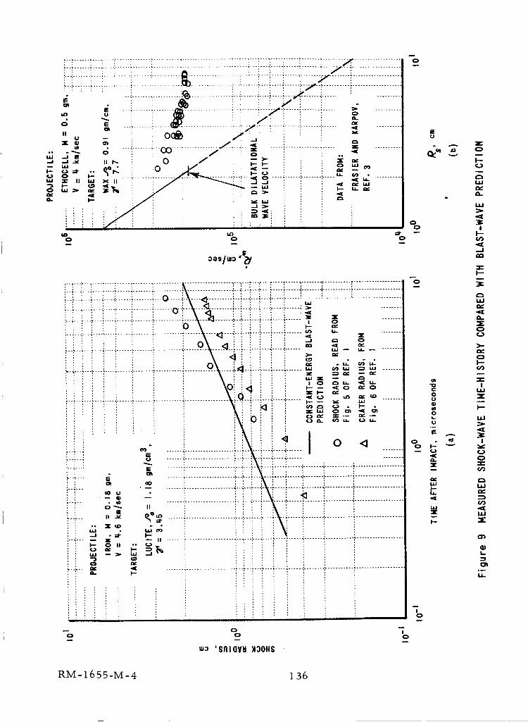
i!;7 [ _ ;_ i i _ Z : !; _7_ .......!........J: ................._. ""l'": ..................{;;{;;i;;7; _:;;' 7;;{;; !............................_ i" ......[ i....i.....i.......Y ........t.................
_ '-i .......:......._ ................. : T'-_--Z! .....f .......!..... =, .........
= --? ....... _...... _ .................... _--hj.!--.! .................... ,,..... _ ........U
= _,® '=' i !..._..._i ......... l!-. z " ",:: _,,,_- _ .......... -i i-,_,=, .....,............._..... _-. .........
I-- i/ i ! .,...,.,
i!i i , i_., , , , ,
I"- h
I0
RM-1655-M-4 136
E
i--
ILl
ILl
,II
O I
-- l--l#i
--J
III
l--
ILl
ZO
O
I-
"O I_" l.i.l
o _.UII m
O
i. ill
U
E .II
-- l.i ¢_
]: -r-
I-- ILl
!0
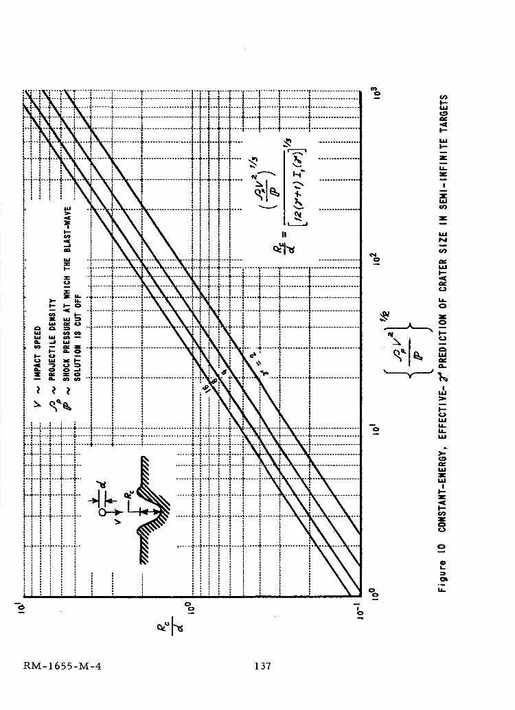
i i
, _ a ,+ , " ................... [.-
:
.........t.................._t-i i
....I ..................I--i--t
iU.I .I--,
1
i
oo
.... t ....
!|
!III
I
""!....i..... _ I.--.I----_-.....
""_'-"_ ..... I
i ..................!
....[....:............._..........., :
i
! :I I
,÷.......,_
i 'l .
I-
I
m
!o
o
o
o
oo
I--
I..-
z
z
I
Xw
z
wN
I.i.0
a.
!
I--
_2
II--z
I--
0
L
LI.
RM-I 655-M-4 137
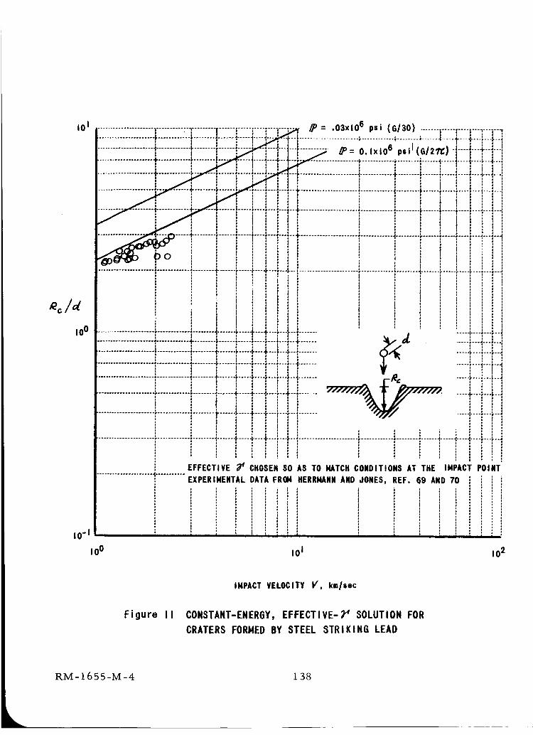
iO i
ioo
I0-1
I 00
;;_ _P= .OSxlO6 psi (GI30) ....... ; | , ,--_
-- t ...................... ; ............ * .........
;
................................... _........ _............ +...+...
.................................. , ................ F.... +---+---
i ,
o
................................... o............... + .... +..o_, ..../
io
.................................................... _ .... +...+...
..................... , ............ , ........ , ...... + .... +...+...
....... _ ..... _ -..._ -..
i iJ o
i
....._....... _._ ....._...
! _ r_,_ .....r-
....._....... -,_)f/ .....;...i -" !
| : ; i , ,.....•......................_............•........•......_.....;...._....
EFFECTIVE 3_ CHOSENSO AS TO HATCH CONDITIONS kT THE IMPACT POINT
EXPERIMENTAL DATA FROM HERRHANNAND JONES, REF. 69 AND 70 ,i i
i i :: ::i
: i i i :: ' : : : :: : : i : :! ' ! : : i
, , I ' ; ; , , , , , , ; ;
I01 102
IMPACT VELOCITY Y, km/sec
Figure Ii CONSTANT-ENERGY, EFFECTIVE-7 _ SOLUTION FOR
CRATERS FORMED BY STEEL STRIKING LEAD
RM-1655-M-4 1 38
I01
i0-1
I0 o
.......... ;--r ........ f , ,o I e......!.....t---_....
............+........I......!.....i....i....
......................_......!.....i----!....i , i ,
' ' , ' Ii * i............ 4......... • ...... • ..... _----, ....
" e i i
' ' 1 i1 ' °
!
I|o
!I
i i: !
if
I
..................... ; ............ | ............... +.=..+_..+_..
_P = .4xlO O psif
, (e13o) :,...,.._1_......... I '!.....;...._...._..,.,.,'' ' ' :
I i_P = 2xlO 6 psi
I
i : !.........., ! ! i
E1
................................................... I--°--4-----}----!I!! I; tti :
o
--_ ...................... f ............ i ........ I ...... 4-----+---+---i i JI ,. , , I , ,l I o " : . ' ' ', , , : : :
i : I , ! : . , ,l ! : l I : ,l I ' ! , , ' ' '' : : ' ' l ,: ' l............ t ........ '............ _"*_ ...... r..................... t ........... 4,........ ,...... ,..... I.... ,....
_ : "* ' ' ! ' i iEFFECTIVE _ CHOSEN SO AS TO MATCH CONDITIONS AT THE IMPACT POINT i iEXPERINENTAL DATA FROM HERRNAN, AND JONES, REF. 60 AND 70
!: ii :
I01 10 2
IMPACT VELOCITY V, km/sec
Figure 12 CONSTANT-ENERGY, EFFECTIVE-_ SOLUTION FOR CRATERS
FORMED BY IRON STRIKING IRON
RM-1655-M-4 139
I01
I0 o
i0"1
,oo
................................... "_...............I" l ..... : .... ;'" ""i i i o
, , t 4 ,, ' ; I
...................... i ............ -I......... I............. , ........I l I o, * ' I ' I................. a............. • ........ 1...... • ..... •.... +....| ; , : :
..................... 'I............ + ........ i ...... " ..... , .... ,---• e a I. | ! o ,
j ' I I I I...................... I ............ J,......... _ ...... +..... ,----,-+-
' : I ! i i' 1 /" ; | |
......................•............ _.........L......:.....,...._.i : I i J/i,'
• i I I i
I i ' '..................... " ............ 1 ............ * ..... * .... i,*--
i o * o__i .....F"T'"o o i 0+ i * I
_ e P e _B o o 1
i a j o o
......................!.........................I i *, : JP il , Z
J. ,,,................................................ , °.,
, /T"' "T T l T :..................... ¢,............ _ ....... r ...... *, ..... ,* ....... _ ,
; i ' , , :...................... • ............ ; ........ "1....... I. .... 4----+ ....
+ s i, .
_t_ ! ! : : :
v-- : . : : :, |
............. -._---ei_ ........... i ........ 4-...... I. ..... I-- -- 4 --.• i i i i
_.n q_, _ : I I , ,o i I o
...... !-I ............. _............ _........ _,...... +.... +...+...g i * *
O_ i i. i * i I
..................... _............. : ........ <...... + .... +...+...o ! / i, , , ,, . t _ ! *
i * / o i; I i : I................................ :........ !...... _ .... "P" ,+'"
i iii
...
"'T ..................... _............ T ........ I ...... I ..... t .... i'"T"I'";........... l i l * * l l *t .............. _ ..................... ,...... ÷ .... +1..+ ....... ,--ii I I i I : I , : I
---_ ..................... a ............ + ........ _ ...... .+ ..... • .... +1...., .._...,• l r l l
I i l u i l I l.--i..................... +.. : ' ; L...L...: ...L.i
I 0 = o.lxI@ 1 1+o1j i'If ..........."_i_I/ "'", I,, .!i ,',, ,',',I' "'"'_'";**''iI
-.+...._.. ............ • ............ , ......... _...... , .............. _..., ....i , _ , l * ; |
I l e , ol * , - I , • ' ' 1
l " ' ' ' ; 1 '_D = ixlO 6 psi (0/271_) j ! !; / i + : + : , i i
i o i , * I--+ ..... _ .......... : ............ +......... _...... l.......... I.-.,--.+.._i/ : , i , ! /
I i i it , , , , ' ! I" I , o i '+ I
: : : , I ,: , : i : I Ii i i *, , I | Io ' I " * o--i ........................................... <....... , ..... _----b--_---l--_l I , I *
l I _ l Ii , I , i Ii * | ", : , !I ; I i ! Ii * *i i ii o i II ' , "
i!!---:--4--
_!.............. _f.f.g .............. V .........
-'t .............. _ "_'"+".II.................. H-.j................... L_I_I .......L
i ! I I I .,
i
........................ t............ !........1......t ....t---t ...... r
i i + I l I ,I I i , i
! t i i i i, ! l |
..................... 'F-- EFFECTIVE _ CHOSENSO AS TO HATCH CONDITIONS AT THE IMPACT POINT..i.. !i EXPERIMENTAL DATA FROM HERRHANNAND JONES, REF. 69 AND 70 i J i ! ii , t * l I , I I
i I ' • I It , I ,, i ! 1 !i, 1 ! I I ,l t l i t I ! _ t I I t f ! i , i i, ' : '' I l ! ! iii!I , I , I , I I I, i I t , :
I01 i01
IMPACT VELOCITY V, kmliic
Figure 18 CONSTANT-ENER6Y,EFFECTIVE-_*SOLUTION FOR
CRATERSFORMEDBY ALUMINUMSTRIKIN6 COPPER
RM-1655-M-4 140
....... to*-"4
s_
...... 4"-----_
...... 4"*-°--I
I5
Figure Iqa
r ........ T ......
,............!........_:.......i
1 i I !: i
.......i IIUI6ET:I
Fe
I0 50
V, ka/sec
THE FUNCTION 2P(V) FOR FUSED QUARTZSTRIKING VARIOUS TARGETS
I0
5
......T"'"!'"'T"'!"-r .............................".................f ...... "T........I'"--!
......t-----F---+--÷---"............................_................t-..........4-.......-_----_
......i---..i...._..._-..i.............................................]- ........_..... _-._i : : I : z I t
......,_-----t----i----i---_............................................+..........._.......l......!ill! | t I i
......:'-----_----t---t---+..............................................._..........4........+......;: ! ; !: ' t . I :' ; , i . i . ' :
......!.....:"_'":"'t..............................................t.........._........T......"i ! i i :
! : ! i i i, ,:, . | . :
l , i ,............,..:,,,vii!_,.----..---.--_-__,_---i..........................__------__.__._,-,...........'........I'......._,i i TAROET:
I i i ,:' . : i __i ' I l/:it "": ! : I _Vdi i i i ! ' i"qt_'lk; i ! i _ ,--; ii I Ta ii iiil ; I _ :I | l I . ' : :• I ; . i t i 't ! !il i i _ Ii ltti i i i ;
5 I0 50
V, km/sec
Figure I_b THE FUNCTION _ (V) FOR FUSED QUARTZSTRIKING VARIOUS TARGETS
P,.M- 1 055 -M-4 141
I0
......i.rTrl .............................+.................f..........1........4
!......!......f---..!---t---i.............................i................_-..........I.........i
t......_tt---,+---!..............................................!..........._........1: l : : ' 1 :
......_-----i......._............................................_..... i......!i : I i :
_-':----÷---_........................................i..........._'........
.....i..--i.'.................................i...i ....'...... i! il i' 'i' i!'"....... i!' .....tTARBET:"
, I I i i I _"I'_ i_
l li._ I ! Ta! ""i i .._i I i ,"i
llii.,l I i !i
5 I0 50
V, km/sec
Figure Iqc THE FUNCTION_(V) FORIRON STRIKING VARIOUS TARGETS
I0
1
5
......F.IF.F! .............................i................_..........._........."o i ....... ,.......FTTTi .............................T................I..... f.........
-" . _ "" ..................................... i.................I............i.........i: i _ : I I I I I
......._.---.'----i---+--i............................._................"..........._........: I : ' : ; ' '
"" "-_.,----.-,----._---+--_-.............................'_................i...........:..........
...... +.....;....._ .... '
_"_ _: _-"_---,_.._ ,_"-'_: Fo
' _ i i i i -'_--._2.e
! t ' :
' i : t
I0 50
V, km/sec
Figure Iqd THE FUNCTION _(V) FOR IRON STRIKING VARIOUS TARGETS
RM-1655-M-4 14 2
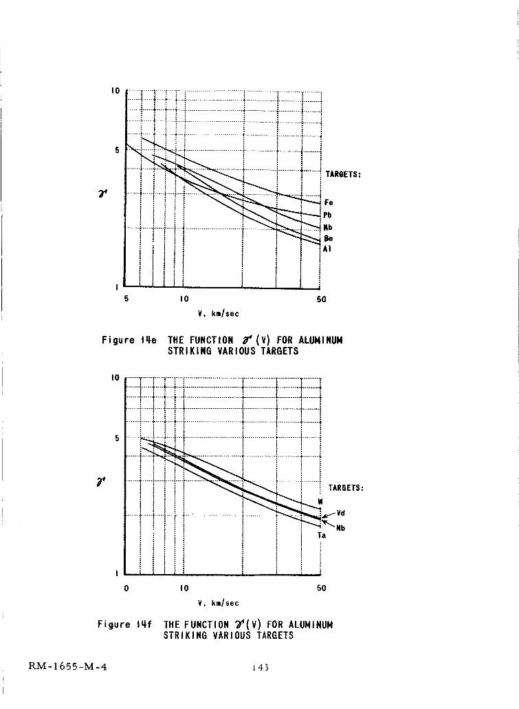
I0
.......L---+----+--._.-.,.............................+................_............i.........i
.......:........__..+++.!.............................+................_............-........
....... ........+...........+........+T.E.._______ _" :'_ S...-.--.i----T.--,--.+_.........................., .............!
i ! _ _ _ , , _Pb
............................................. Nbi ! _ i I ! ;._"-'_"_!se
iiiji i +5 I0 50
V, km/sec
Figure Iqe THE FUNCTION 34(V) FOR ALUMINUMSTRIKING VARIOUS TARGETS
I0 ............FTT! ........................................................._........T............t"''÷'-+''_,.........................................................t.......
t ! ! " i............ +....+...+..._ .......................................................... l........ +_
' ! I I I :'.....I.._.L..._..... ,.............t, ....................................................I.........;l : : : : j
.......... ÷-+:-+" ............................. T............................ 4 ........ ÷l t : i , | I :
......._._L..+..._..............................+................,,+...........+........+, ; i+ i m t i
...... _ ......+................+...........+........+
, ; : ; I 1 I l
I : i + TARBETS:" t "r---r-:.-_ ........................... i...........:........."
I......___.,_-VdI i _ ',,'__ __".b
i ' : : _ iI ! _ Ta
0 I0 50
V, km/sec
Figure 14f THE FUNCTION "Z'(V) FOR ALUMINUMSTRIKING VARIOUS TARGETS
RM-1655-M-4 i 43
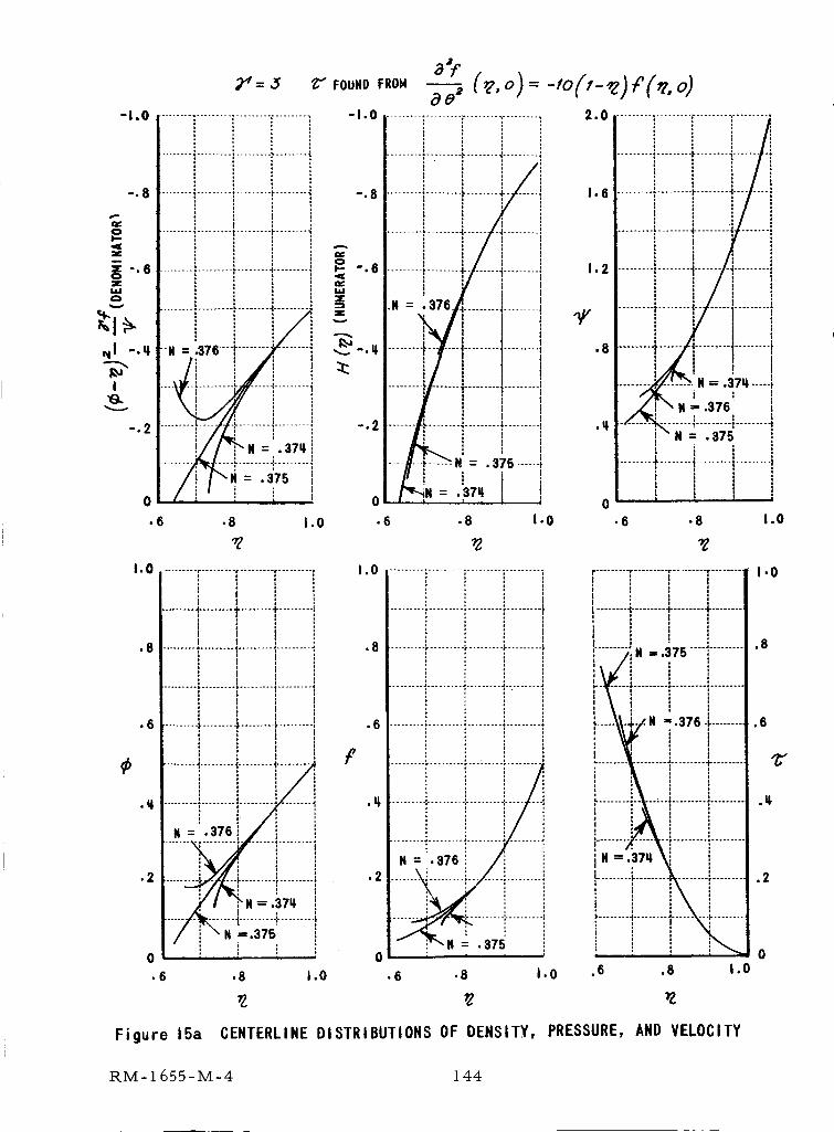
"1.0
a_e _
...................................... -I.0 ............................ •.......... 2.0
-. 8 ....................................... • 8 _ ........ _-i
0 0
• 6 .6 .8 1.0
1.0 1.0 ......................................
.8
.6
i
• 8 i.0
.......... r ......... r ......... _ .........
I
.8
......... -_........ -_......... _........... 6
fi i : i
._ .........I.........i.......': I/i :
I, :.37 I
' , I
l .....i
• 6 .8 1.0
,q
.2
......... • ......... J ......... J.: ....... •
IiI
illillliiiiiillllilllllliillillilll
• 6 .8 1.0
Figure 15a CENTERLINE DISTRIBUTIONS OF DENSITY,
RM-I 655-M-4 144
1.6
1,2
.q
0
......... I"........
!I
N = .37q .....i
N =" .376I
....... .........•.........N = .375
........_........i.........I........,I I I
• 6 .8 1.0
Y
r ........ ,r ......... r ......... " ........
t .: :I........._..........+........+........i
, I
i ll I
....... ;,_N -=.375 .....",'........., : : ,I J
...... ......... ......... :.........
L N -.376 i- .........
,. ........ •....... :......... ; .........
I i i :F-.......' --"........._........., I :
j N =.37q : i
...............I
.6 .8 1.0
PRESSURE,AND VELOCITY
1.0
.8
,6
,q
.2
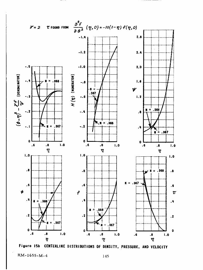
0
Figure
.6 .8 1.0
........t-........t-...... -!,..... !i t Il
..... l"............ -r .....i !1 i1 I
........ L .......... _ ...... 4
mi .m,-/ .......
•...._-_--i.....!
I_-,: --,_I _ i i.6 .8 1.0
0
!......-i,......T--I .....
i ............... ,I ......
° ,1
IL.ii ......
....... -I-....... _....... ". i.......!, N.
• 6 .8 1.0
15b CENTERLINE DISTRIBUTIONS OF DENSITY, PRESSURE, AND VELOCITY
0
RM-1655-M-4 145
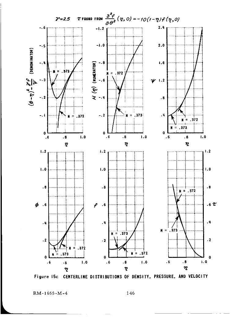
-,6
N = .
i
N = .373!
0• 6 .8 1.0
I. 2 ........!............................ ,
........ -_ ......... _ ......... ; ......... Z
ii
I. 0 ........ _ ........*........ _........4
!
• 8 ......... '*................... ".........
!t!
........_.........!.........I .........i !
' i I• 6 ........+........* ........._........4,
!
i 1 lJl
........i........i......Y-iIN----is_§TT .........t
0 i 2
.6 .8 1.0
?Z
i :-.5 ............................+........_ -I.0
--_-., _ _ + _ _-.s.............................
_ -.2 _ -._
-.I -.2
.6 .8 1.0
i.2 ...................i.........i.........i: t
................. _ ........ 4, ........ 4
I.o ................i.........i.........i
1......... I ......... t ......... | .........
.8 .......................................i1!
i................. _ ........ _ ......... |
1 l
i I_._ .........4,,!!..........................
.........i_i!.........................
•_ .........I.........i.......i.........iI
........_......... ......._........
.2 .........i..... _.........i.........i
N = *373 i0 i i I
.6 .8 1.0
Figure 15c CENTERLINE DISTRIBUTIONS OF DENSITY,
4.......
%......
t
........ t, ! ...... 4"
i .........i
........ 4, ........ 4,
.6
i N = .372 if ........_,
.=._ ! i: :
.8 1.0
_Z
I ......... "......... 4- ........ 1 .........
: ......... t ......... t ...................
t, ......... ; ......... _......... , .........
i i ,1 i '
!lf ........t ........t ........
t
1
_..__._;...._..._........._.........i/ ! i
N = "373 ""\i" ........i .........
.6 .8 .0
PRESSURE, AND VELOCITY
1.2
1.0
.8
.6"C"
.q
.2
RM-I 655-M-4 146
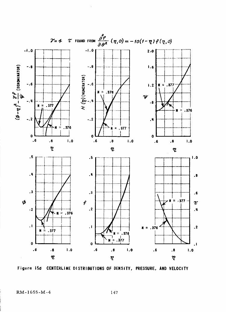
;_=4- "t" Fou.oF_o._ (,z,o)=-to(t-_;£(_z,o)
-'"° I...........=--*__._!i ii: -"° I........_'_................T ]-].....t t _ / /
_ .._r___ _................. -._I I _ fill= , i l i ........I.........•...............
z ........6 ¢-!...... "i........ !--_..... _ -.6
--, i i ; /j_
_.._ N= .3 ll---t_--_-4--H :_s , 1 i
-.2 -- -4--- , ---_-----,,' -.2
O" " ! 0
.6 .8 I .0 .6 .8 I ,0
.5 "l.5
.q
.3
.2
.I
! i zi i i i
........• ........ t....... ".... ...4,
........+........i...... i........-i
...... •i,-........ " ..... 4........ -i
......... !........: .......4
N = .377 I.........,i-.......................... .;
' i; t , l
;o
.q
.3
.2
.II
N = .376' i
0
.6 .8 I .0 .6 .8 1.0 .6 .8
2.0 ........ : ............................ i
1,6 ............... -ii __
..._....... i
• 376
.q, .... '.....4.... _-.......i
t ' i .I......._....._......._......i ! ! i _
0 I i _ ; l.6 .8 I .0
i i T'---T---i i i iH-_--h-_......
! ] ,......_--k.....
t I l
..............I-_•"N = .377---
.... _-_-
: :_. !" = ._?_ ....i -......., .........:._...... ..........
1.0
,8
,6
.q
.2
.I
1.0
Figure 15d CENTERLINE DISTRIBUTIONS OF DENSITY, PRESSURE, AND VELOCITY
RM-1655-M-4 147
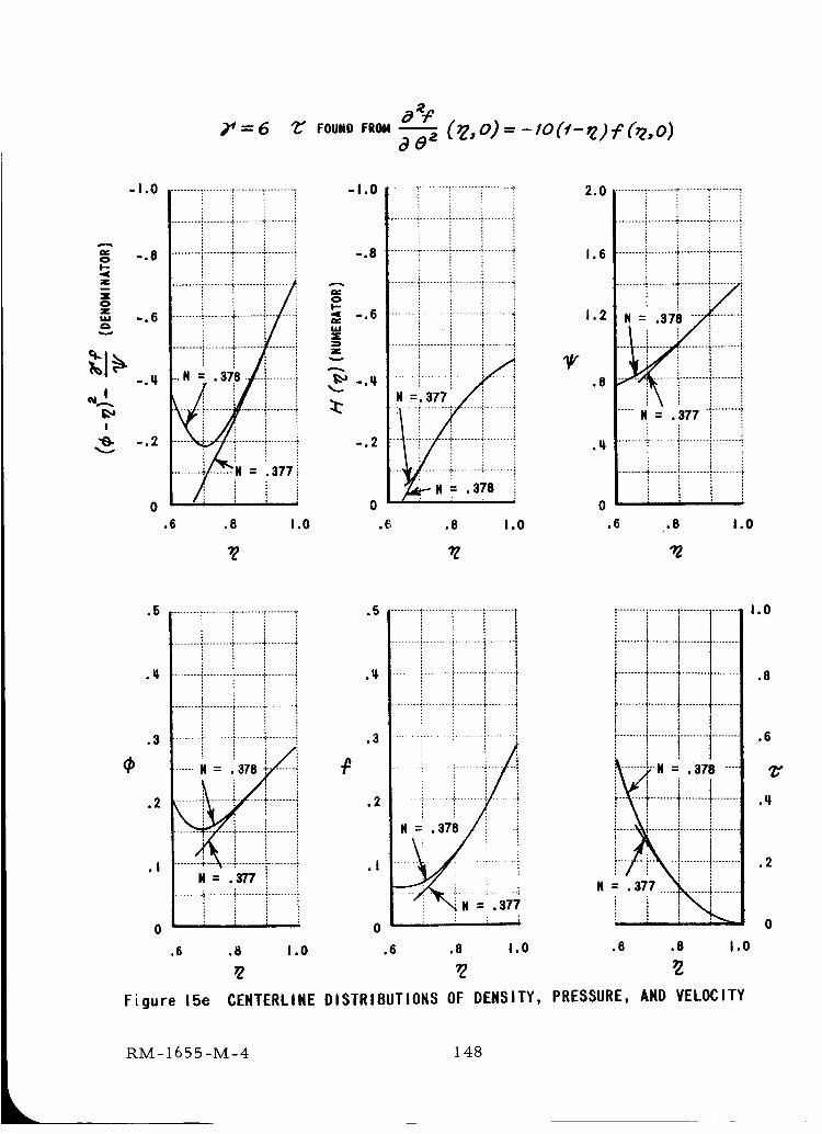
-I ,0 ............................:.........;
OI--"I(Z
0Zi,ie_
I
"e- -,2
..................•. ........_.........
-. 8 ..................":"........"_.........":
-. 6 .........i........,'-.........i
.........i........-_................. i
, --.378/ .........i
.... _......... ' ................
...... L .._.........; .........
........_.......:N = 13771
0.6 .8 1.0
-I.0 .......................................
........ .,......... . ......... :
0I--
< -.6 ........._................. .*...... '"" : iI,l,I_r i .
-. 2 ........ i....... _........i..........:
0
,(_ ,8 1.0
I//"
2.0 ..................."........'".........
I. 6 ..................-i-........._..........
1.2
.8
,q.
.......!:!::::i::::::::I..... N = .377 "'i.........:
i
I i 16
.6 ,8 1.0
¢)
..................i.........i........i..................i-........4-........_.
• I_ .........:........._-........._-........,:
...................-........+........,:
• 3 ........_.........':........_.........i
......,-. i
• 2 ........i ......_...... ".........
N = • 377.......-i........_.........:..........
; ,0
15 ......................................
.II.
,3
,2
.I
........ ° ......... , ......... . .........
.........._.........?........._.........
0
,6 .8 1.0 .6 ,8 1.0
t
t
, i: ...........N = .378 .....
i i i i...... _........._........._.........
. ........
,6 .8 1.0
Figure 15e CENTERLINE DISTRIBUTIONS OF DENSITY, PRESSURE, AND VELOCITY
1.0
.8
.6
¢,
.2
0
RM-1655-M-4 148
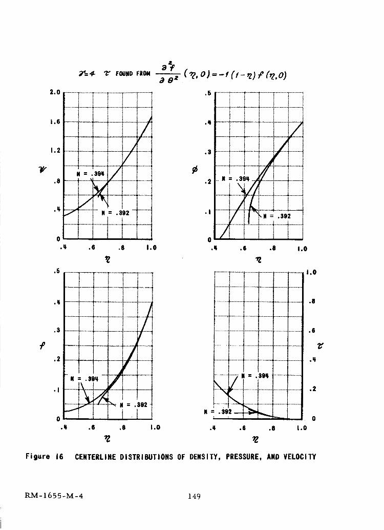
le
_"g"¢" _ FOUIID FROM
"°i........i........i........[.................[........]1.6 .........i......._ ...... +.................. --'--_*
i i /-i? i '/ :1 l ! .-/, ....... to.2 .........r........t........t .......i .
........4.......4........_......._ ......_,........;I
. = ..,sl/i i 1
' t t, t t ! ........t................. 4........
"_ "- . 2 .....
1
t ....f........i........].......f......o .......i-! ! I ' j
• _ .6 .6 1.0
.5
.q
.3
.2
.I
"Z
It .: .$02 "J' i : i! t l t
0
.tl .6 .8 1.0
a_$ 8 z
( _, o/--1(1- ,z) _ C_,o)
.3
.2
.5 ........[........T....._........r........_........":."
.q.i i ii i i.......4....... .4.........s,.........]........._.........._
::::::::::::::::::::::::::::::::::,............._ii........ _!................_.........;..............__ .i'!
; /I;.. _ii "i s........._,... i.........4....... .;=.-.-
0.q .iS .8 1.0
r....... ;.........?.........I.........
!.........i.........i........I.........i........_........_........_.........t................._........_,........I t
I !
! i tI........'.........!.........i........i ...................i ! 1 :................_........, ........_........4.........t
.........[.......iI ,_.i _ i • I........t '"'_'_t_: ......÷........-_........• ........l
.- .3_'__ i ? I: i l i _"l'----- ; I
.t .8 .8 1.0
1.0
.8
.6
.q
.2
Figure 16 CENTERLINE DISTRIBUTIONS OF DENSITY, PRESSURE, AND VELOCITY
RM-1655-M-4 149
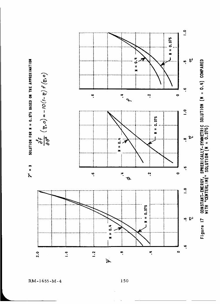
I0iI'--
ZnX
0
L
'dC
Z
0
EU
,mEO_
||
Z
0
I
-J
II
I
I
II
o
o i i t !
';......... '_........ _:..... - --" ...... 'I"........ *--' o" ._.o t : i I o, : , i ,'l_ , : . Ii I i t o il i t I i i. , ,, i ,,-. III I I I l
! : _......... _ .... ;"_-_'---_--J7 '_ I = ii,.,i,.llt o i o, : : ! ,, ,,_ _, It , : : , ,, : , ! = i\ • n _:
itP\IXI",, ,",.........,": ,": ," .-.°o : s i o
, I ' , ; I 1 I _ c_II
_0 _r _ 0
; : \\: , , _ ,¢ l ' i l
L ' , , " ".................. *+..... -%-._....... _........... o ............o i o i i! N\ : :,, :, : , , : :, _ ,,_\, ,= ,
i I t o i1 ' t:..................i........'.-X-.-_.....---.J.....,.........
t I • ' ,
................................... "I, "',_ .........
, 1i , I n
tO _1" _ 0
0
O0
0
i i:!........................................................................i.i.........i.........n o o I t I • o I+ o l i t o i, _ _-_L , o, ,: : : , : : : ,,_' .___._-_.__,,........._.... ,,. ........,_....t i i + i i, + ' ', ; i_i o • o • i o' ' : ' ' I I ,, i i i i = ",,,_ , ,i o • o o o i
o l i : u i o ,._----'_-:,_--- _ :o i t o , ii I o , o i *
I o n o 0 • ot o t o o o i ii t i : o * , * II * , , i o *•. * _ n ' ', , ' 1 i ....
Z
Z
0
I--
.--I
0¢#2
I I.,[')
_" |l
I Z
'--JI
<[0
--I--
LLI ._I
ZUJ
UJ I-
i.-
8_
L
°_
0 _ _
e_ - -"
RM-1655-M-4 1 50
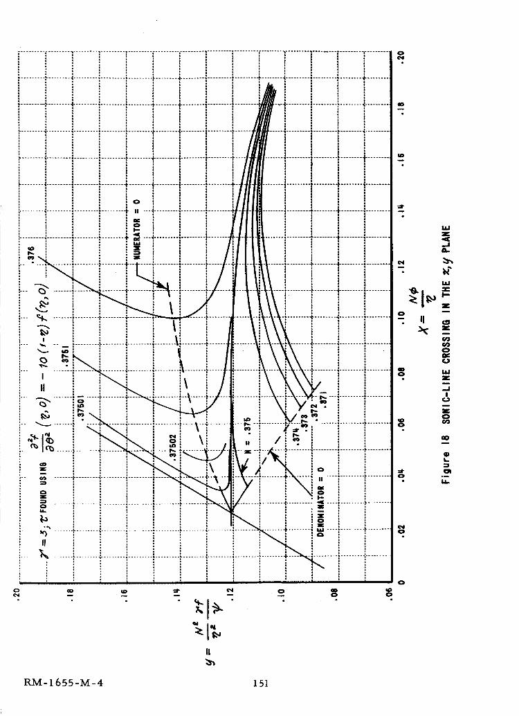
................... ' ......... " ............................. f .................. i ......... f ........ Y ........ ; .................. " ........., I I Io i o
I l ! Io o o
..................._........._........._......................................i,........4........a,.........i..................+........I I ,
a m |I
........•........4".................."..................÷ lI
I
I
...................................... " ........ 4"................. t ......... I"....
.......'4...........................÷ .......-..........I.
..........................."......... II ----I-
: _"_
• i -7 ',.. ............. ,_........ +_ . ,. ,Q n o o , _ , o
, " I , 1o q i_ o o o o iI _ o o o o
_ ',,,, _ ...._ o i j o
,--- _, ....... , .................. _. iI
I............................v........._......
o •
i 0
........_.._......a _
,--_ I_.......i........!......
,.. -_ ....... '_........
Z
_4 ......... i ......... ,. ........ ,l.........
0
........-_........4...................
" _i .......... ,,_, ......_...................
" ,, .... ÷ ........ ._......... o......... ,..........
0
n .............. 1- ........
°_
II :
' " i i
II
0N
z
_J
zm
o II _=
X
0
0
0
o
!
i
z0
_o
4)L.
G_
RM-1 655-M-4 151
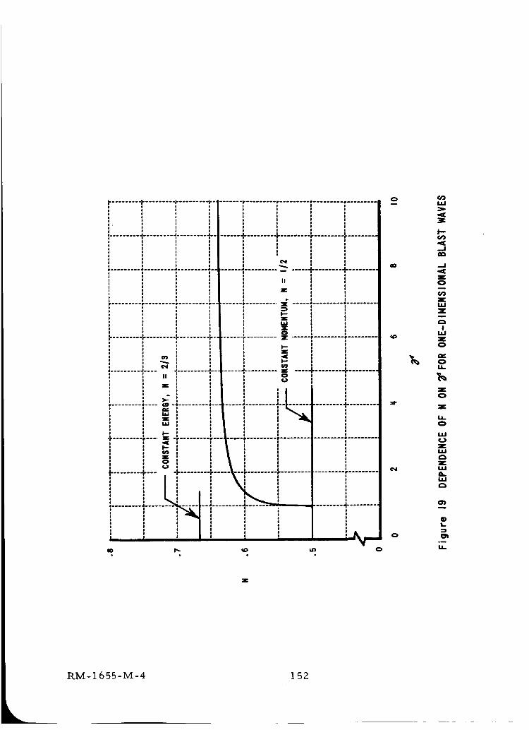
a ......... J ......... J ......... .J..
4, • •
...........................................• r t •
I-!
1!
...... "1"........ 4"......... r ......... I-.........
iLN
......]...............T........T...................................... • • r
g........ + ......... _........ + ......... _......... _ ...... r ......... _.........
I II i
I I
_i I _ °................. + ......... = .... + ........ + .........b.............
e 0 a oI I I
I I I _ I I
I # It !l I I.I II I II I
_1 1 I I I..... • ......... J ....... . .............
I I I I I
I Z! I I I II I O l I IO _l I I I OI I I I I I
I pI I I i II I o I I I
.......... , .... _ -, ................. _......... o.i
!| !......... +--- . "1"......... r ..... L"-_ ......... I..........
Li,I I I I II I I I II I I I II I I II I I lI I I I I
' 1 :.................. -,_-;--} ........... + ....... .
J J! !! I
.........!%_........
ow
I--
.JIIo
..I
z0
zwZ
I
zo
0
z0
z
0
ILl0ZUJ_3ZILlQ.IJJC3
O)
Q)L
o_
EL
Z
LRM-1655-M-4 152
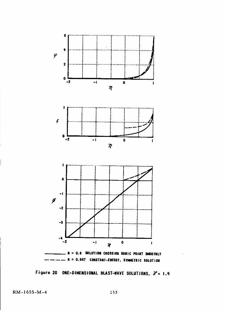
0-2
"l ..................
II _ • • i
.........i.........i........!........-I 0 I
_T
F
0-2
.................. -,........ -................... r........ ]
......... •........ -F........ 4- ........ •......... ".....O e I e
! e I _.... _ I' _i, , ! , :
i I i ! ,1-I 0 I
F-I
-2
-S
i t [ ]I ! , ,
0 * , , ,_ jir I|
! j j/] i.... ._.. | 0 I, !- , 7! ........! !
' ' _/'i j0 I I e I iiI I I t
I I II O i !
I "1 I...... , I /i i 3 ," "'1 ........ T";F"'I ......... : ......... t ........ -I
I I I I I II l I , I,2" i i 1I I I I ¢
I I I 0
.......o I I I I Ii--/--4.......4-......i........l.........Jf : _ I
_,, ! 'i 1! | 0
-2 -I 0 I1'
N : 0.6 SOLUTION CROSSINO SONIC POINT SNOOTHLY
-- N : 0.667 CONSTANT-ENERGY, SYMMETRIC SOLUTION
Figure 20 ONE-DIMENSIONAL BLAST-lAVE SOLUTIONS, _'= I.q
RM-1655-M-4 153
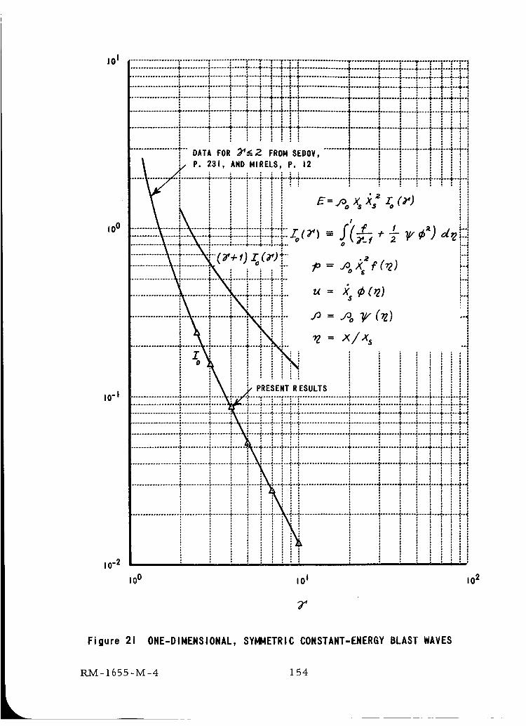
jO I
I0 o
I0-I
I0 "2
.................. _........... f ....... _..... _,""T ......... :"t .............................. ; ....... _..... .s----*---_---f --'=--IJ P * • ' ¢ o o ' ' . . ¢ o
.................. I- .......... • ....... ; ..... ,--'-+ ......... _--t .................. -F .......... _....... I ..... 4,'-"$"'""° ..... 1o : , , : . , , , , , : ' : ! ,
.................. 4, .......... _,....... t,...... ;'----f .......... 1--t" .................. _.......... + ....... =...... _-.- -1---4---.,--4.--:: : , : . :: : , . : , . :::
................... ".......... ;....... t'"'4,""_ ......... I-I ................... !.......... .i-...... 4...... "-.--'-...i..-'--+-4: , ; , , , : , : , ., , : . . . , . , , .... : :
.............................. 4. ....... • ..... "--'1" ......... $--I. .................. .¢-.......... I........ _..... --.-.+.-.$.o÷ ..... ,
: = ; ' ' : : | ! : : i :' :'= = | = i o l = = * : = •
.................. ÷ .......... o....... ;..... +---4" ......... ;--,_ .................. 4. .......... .,....... 1...... I.----,---., ...... ,---; : , : | , , | : , , : = :
.............................. + ...... + .......... :.......... +-+ .................. ;.......... +....... _.............. 4,--.i-..... =
.................. _"'" DATA FOR _-_ ,2 FROH SEDOV, ...................T t:....... _':..... +"4,'":'"_{"{:: : : :o , , , : , : ,
, o , , , I , o :/ P. 231, AND HIRELS. P. 12 , : : : : : : : .v - : o ° , o ° D
. , , , o . ° o, , ; , . , , , : : , : , ,.......... 4" ....... ;- -- _,-- -I-- -I- .................. 1.......... 4, ....... " .......... t----$--4"--$o4
, , : , , : , . ,
"2
i_[PRESENT RESULTS
........... • ....... * ..... 4"---4'---
...........................r...-!.-...+.+ ............................. +......+..... ÷.-...:....--+-_ ................... • .......... t- .......
..4,.._.............................. _....... _..... _.-.._....: i
........... • ....... • ..... ,,[-.oo÷=.°
: |
..,,..,,................... :.......... _....... :...... ,_....÷....: : , : : , ,: : ! : : : [. o , , : : ,. ° , ° , °
--4.--I. .................. • ........... $...... 4- ..... *,----*. ....[ ° ,
: t ....... t ...... :'--'-_ ....
°
"°4.°I
|
I0 0 I01 102
Figure 21 ONE-DIMENSIONAL, SYI_J4ETRIC CONSTANT-ENERGY BLAST WAVES
RM-1655-M-4 1 54
O
O
OO
X
a
!
OL
O
OL
o_
O
RM-1655-M-4 155
•r ......... r ......... r ......... • ......... • ......... 4 ......... J ........i i j i , i -1':......... _,......... + ......... _......... ?......... _......... _.........._, , , : , , , 1[_ .J......... J.......... _r ......... r ......... . ......... • ......... ° .......
' ! 1 !......... _ ......... j, ......... _ ......... a, ......... Jr ......... r ...... #r .....
• 1 * i #: . . , , . I/......... , ......... , ......... . ......... J .................. _- ...... r _0
O
i ----.......... • ......... , ......... , ......... _ ......... J ......... j_.
o •
%, ......... J ......... J ..........
4 a *
J• |.............................. .,......... + ........ + ......... _,
• j
r ......... * ......... • ......... J ......... J ......... J .........o i
*
pi: 0: o*0
......... .J......... + ........# a
......... , ......... • ......... J ......... J .......
. I :
: i i i
0 o i
J #
- + .........
a
g
.-g ......... ÷
-! ......... i .........-_. ....... !..........
.__ .................
0
I!
ii!_r .... _ '_.........I # * v_
-.I
:1 ! r, , _.,
........ 4 ......... _ .........., ,, _
. , , ;' ' ' % _ _n• ......... # • .........
..... r ......... , _.........
..... _r ........ _ f ......... _
,, ..........,: _ .........
I
p
!0
u I I ,ill I i I " | n i
RM-1655-M-4 156
i
i
Z
-o _ _
u0 ,Og SflIOVU a3_VlO
0
Z
t,- _ Z
"' _ .=.
_. ,.,.,
..=._...=.
°_
U.
0
0
RM-1655-M-4 157
,m
ol:
I0
8
i
s
................... _ ...... NORMAL .......................
t
: °°| a
POROUS
......... • ......... • ......... k
......... ,t ......... • ......... t.
..........
.......... F........ ",................... "-........ +-
7.85
jo (omlc 3)
Figure 25 HUGONIOTS FOR NORMAL AND POROUS IRON
RM-1655-M-4 158
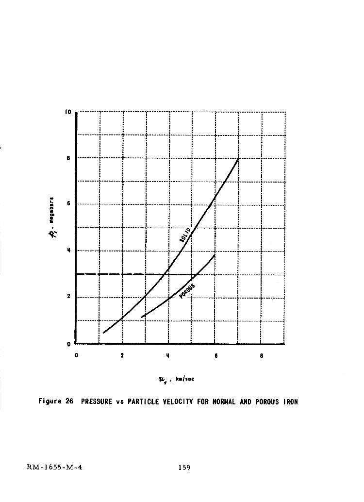
elL
elAI
IgOI
|......... 4-........ 4
...... t ........ • ......... I. ......... I
F! i
..-_ ........ 4......... , ......... ,_.........
Z
I
I
0 2 q 6 8
_,f , km/sec
Figure 26 PRESSURE vs PARTICLE VELOCITY FOR NORMAL AND POROUS IRON
RM-1655-M-4 159
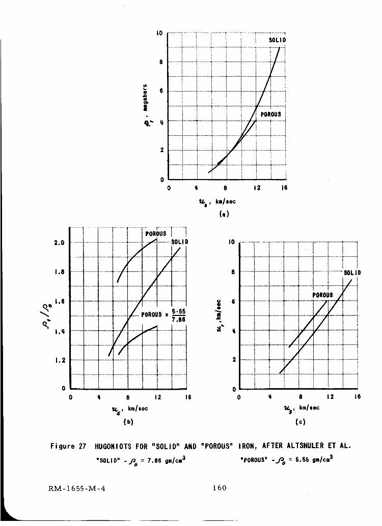
2.0
1.8
1.6
l.q
1.2
0
I0
IoL,. 6.0
I@
|
9." q'
SOLID
: !: !
........ i .................. F........ 4..........
iJ J
............................... _r--4 .....
m ,
.................................... 4
0
0 @ 8 12 16
......... ,......... _,........ 1POROUSi !
SOLID
/°i
POROUSx 5.557.88
I
......... 1
!
l&S, km/sec
(°)
iIt
e
It"
I0
iiiiiiiiiiiiiiiiii iiiiilliiiiiiii
i It i I ' i 0
0 q 8 12 IS 0
W,.$, kmlsec
(+)
q
......... i ........................... "+......... i ........ p......... p ........ ",
......... ; ......... _ ........ +....+.-..I ......... I ......... p......... _"........ 4
t t ti i + t + : ii ' .-+........+..... i........+- '.................. l .... . . """ ........ SOLID
t i t .. + i i + +, i/......... +.......................................... +......... i....... +
t i t i+ i i ] POROUS/r ]
......... •......... .,'........÷........ I.............. --..r----/-+"........ ;t i t i/i/ ! tl : i i : , : !.........i.........i................+.........+i.....l.......l.........++ + | i/i 1 t
.........I........+........:+.........I-:I+ ........l.........i! i . ] ! i i
I ! i / / : i :..........i........+........+.i-. ,.]..-..........+........_.........
i t i i I, t J I lI ft • l i........•........+.................:_........+........+.........+: i : : ii ! ./+........i I ! i
........ ! ......... p ........ , ........ .......... " ......... I"........ ,......... ;L : ' ' l l , :
E i i i i i ! i: l ; i ' t :
q 8 12 16
"14,,$pkm/sec
(c)
Figure 27 NUGONIOTS FOR "SOLID" AND "POROUS" IRON, AFTER ALTSHULER ET AL.
"SOLID" -/30 = 7.86 gm/cm3 "POROUS" -j3 o = G.SG gm/cm3
RM-1655-M-4 1 60
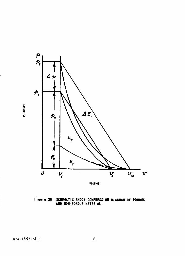
M.I,v:)(n
(n
L
o _ v', % v-VOLUME
Figure 28 SCHEMATIC SHOCK COMPRESSION DIAGRAM OF POROUSAND NON-POROUS MATERIAL
RM- 165 5-M-4 161
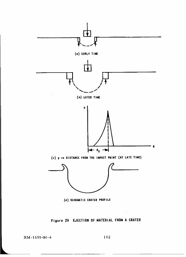
(a) EARLY TIME
\ /
(b) LATER TIME
P
•_-R s --_
(c) p vs DISTANCE FROM THE IMPACT POINT (AT LATE TIME)
(d) SCHEMATIC CRATER PROFILE
' " R
Figure 29 EJECTION OF MATERIAL FROM A CRATER
RM-1655-M-4 162
Tab] e I
HUGONI OT DATA
11s= C + Su r
MATERIAL
SILVER
GOLD
CADMIUM
COBALT
CHROMIUM
COPPER
MOLYBDENUM
NICKEL
LEAD
TIN
THORIUM
TITANIUM
THALLIUM
VANADIUM
TUNGSTEN
ZINC
BISMUTH
IRON
ANTIMONY
BERYLLIUM
MAGNESIUM
INDIUM
NIOBIUM
PALLADIUM
PLATINUM
RHODIUM
TANTALUM
ZIRCONIUM
ALUMINUM
LUCITE
FUSED
QUARTZ
,% c, -_ocz GI2 Trgm/cm3 km/sec S MEGABAR$ MEGABARS SOURCE
1.6_ 1.09q II, 65I0. q9
19.2q
8.6q
8.82
7.10
8.90
I0.20
8.86
ll.3q
7.28
II.68
q..51
I 1.8q.
6.1
19.17
7.1q
9.80
7.87
6.62
1.82
1.7q
7.31
8.57
12.0
21 .q5
12.qq
16.6
6.5
2.7
1,18
2.20
3.22
3.06
2.ql
q.65
5.18
3.97
5.17
q.67
2.07
2.67
2.08
q.79
1.82
5.11
_.00
3.0q,
2,0
q.o
2.0
7.98
q.q9
2.37
q.q5
3.79
3.67
q,. 68
3.37
3.77
5.85
2.59
1.30
1.61
1.72
1.51
1.5q
I.q8
I. 20
I.ql
1.52
I. q3
1.88
I. 07
I. 57
1.21
I. 27
I .58
1.36
I. 59
I. 67
1.09
I. 27
1.61
1.21
1.92
I. qO
I. 6q
1.15
0.93
I.II
1.800
.501
I. 909
I. 902
I. q.oq
2.73
1.930
.qBq.
.518
.505
1.033
.393
I. 592
3.07
.661
,392
I. 259
.265
I. 157
.351
.q.II
I. 695
1.726
2.89
2.72
I. 890
.92q
.92q
0.069
O. 0069
0.21
0. I_
0.21
0.0062
0.062
O.Oql
I .51
I. 56
.0792
.0372
0.0021
O. oq8
REF. 7.
,!
_P
REF. 66
REF. q3
RM-1655-M-4 163
Tab1 e 2
N(9") FOR ONE-DIHEHSIONAL BLAST WAVES
7
I
I.I
I.U,
5/3
2.8
O0
1.001
I.I
1.2
1.3
I.it
1.8
2.0
2.5
3.0
It.O
5.0
7,0
I0.0
100.0
I000.0
3+1
O0
21
6
It
2.1111
I
2001
.5
.56888
.6
.61073
.62670It
.6Itl6
.5106
SOURCE
REF. 28
w
R
N
@
PRESENT REPORT
21
II
7. 6667
6
3.5
3
2.3333
2
1.6667
1.5
1.3333
I .2222
1.0202
I .0020
• 5683
• 58It3
• 5935
• 6000
.61It3
.6182
,62ItIt
• 6279
.6321
,63Itl
• 6365
,6385
.6Itl2
,6It 16
RM-1655-M-4 164
Tab1 e 3
STAGES OF I_IERGY TRANSFORMATION DURING IMPACT
STAGE ENERGY TRANSFORMATION DURATION OR TERMINATION
to ELASTIC DEFORMATION K.E. TO STORED MECHANICAL ENERGY
2. PLASTIC DEFORMATION
3. SOLID STATE PHASE
CHANGE
_8
K.E. TO ABSORBED MECHANICAL
ENERGY
K.E. TO ABSORBED LATrlCE ENERGY
HIGH PRESSURE
COMPACTION
5. SOLID/LIQUID AND
LIQUID/GASEOUS
PHASE CHANGES
6. GASEOUS EXPANSION
(EXPLOSION)
7. BLAST WAVE
8. GASEOUS/UQUID AND
LIQUID/SOLID
PHASE CHANGE
9. PLASTIC DEFORMATION
I0. SHOCK WAVES AND
STRESS WAVES
II. FRAOMENTATION
ABSORBED MECHANICAL ENERGY TO
THERMAL ENERGY
ABSORBED MECHANICAL ENERGY TO
THERMAL ENERGY
ABSORBED THERMAL ENERGY TO
MECHANICAL ENERGY
ABSORBED THERMAL ENERGY TO
ABSORBED AND STORED MECHANICAL
ENERGY PLUS MECHANICAL ENERGY
RADIATED AWAY FROM TARGET
ABSORBED THERMAL ENERGY TO
MECHANICAL ENERGY
DYNAMIC MECHANICAL ENERGY TO
ABSORBED MECHANICAL ENERGY
RADIATION OF MECHANICAL ENERGY
STORED MECHANICAL ENERGY TO
ABSORBED MECHANICAL ENERGY
ENDS WHEN INTERFACE PRESSURE
EXCEEDS DYNAMIC YIELD
STREN GTH
ENDS WHEN INTERNAL ENERGY
EXCEEDS LATENT HEAT OF
SOLI DI FI CATION
OCCURS IN SOME CRYSTALLINE
SOLIDS AT ELEVATED TEMP.
& PRESSURE
CONTINUES UNTIL THERMAL
ENERGY EXCEEDS REMAINING
KINETIC ENERGY
OCCURS WHEN LOCAL TEMPER-
ATHRE EXCEEDS HIGH PRESSURE
MELTING OR BOILING POINT
OCCURS WHEN LOCAL RATE OF
ENERGY ABSORPTION EXCEEDS
RATE OF ENERGY RELEASE BY
MECHANICAL OR THERMAL RAD-
IATION
EFFECTIVELY ENDS WHEN RATE
OF ENERGY RELEASE FALLS
BELOW THE STRONG SHOCK WAVE
VELOCI1Y
OCCURS AS THE OUTER TEMPER-
ATURES OF THE ENLARGED
DAMAGE AREA FALL BELOW THE
BOILING AND FREEZING POINTS
OCCURS MiEN BLAST WAVE
PRESSURE EXCEEDS DYNAMIC
YIELD STRENGTH. ENDS WHEN
STRAIN RATE BECOMES LESS
THAN WEAK SHOCK WAVE
VELOCITY
CONTINUES UNTIL ALL DYNAMIC
MECHANICAL ENERGY IS
ABSORBED
OCCURS AFTER RAPIDLY DEVEL-
OPED HIGH COMPRESSIVE
STRESSES
RM-1655-M-4 165
Tab1 e it
PHYSICAL PROPERTIES OF SELECTED SOLIDS (AT ROOH TEMPERATURE)
MELTING OR
DENSITY SOFTENING
p POINT
MJTERIAL Om/ cm3 °C
PLASTICS
POLYETHYLENE 0.90 IO0°(S.P.)
POLYSTYRENE 1.06 86°(S.P.)I
LUCITE* 1.18 85°(S.P.)
SOFT METALS
INDIUM 7.28 156 °
LEAD 11.3 327 °
SOLDER(6OSn-qOPb) 8.52 188 °
METALS
ALUMINUM 2.71 660 °
DURAL (17ST) 2.87 5qo °
COPPER 8.9 1083 °
STAINLESS STEEL (3qT) 7.9
IRON 7.7 1535 °
TUNGSTEN 19.3 3qlO °
BERYLLIUM I.Bq 1278 °
GLAS_._SS
PYREX 2.23 820°(S.P.)
FUSED SILICA (Si02) 2.20 i870°(S.P.)
CERAMICS
HEHATITE (Fe203) 5.20 1565 °
MAGNETITE (Fe3Oq) 5.18 1538 °
CORUNDUM(AI203) 3.98 2020 °
SILICON CARBIDE 3.1 2600 °
POROUS SOLIDS
IRON (P = 99.3_) 0.06 1536 °
IRON (e = 93.55) 0.5 1535 °
IRON OXIDE (_-99.1_) 0.05 _,_1550 °
(P=90."`%) 0.5 .,.1550 °
YDUNG° S
MODULUS
Y
IOBpsi
O, II
0.78
0.58
I .57
2.3
"`.5
10.5
I0."`
18
28 ."`
29.9
62.5
"`"` .8
9.0
10.6
3q
33
59
68
_0.3
<0.3
BULK
DILATATIONAL
WAVE VELOCITY
CI
km / sec
2.0
2."`
2.7
2."`
2.0
3.1
6."`
6.3
5.0
5.8
5.9
5.q
12.9
6.6
5.9
6.8
7.3
I1.0
12.0
<2
"9=2
DYNAMIC
SHEAR
MODULUSG
106psi
0.065
0.19
0.21
0.5"`
0,78
1.58
3.6
3.9
6.7
II.0
11.9
19.q
21.3
3.6
"`.5
15
13
23.5
2"`
0.01
•,,,_ O. I
0.01
0.15
SHEAR
WAVE
VELOCITY
C S
km I sec
0.5
i.I
I.i
0.7
0.7
I.I
3.0
3.1
2.3
3.1
3.2
2.6
8.9
3.3
3.7
",.IS
"`.2
6.q
7.3
,,,=1
,<1
" LUCITE IS A TRADE NAME FOR POLYMETHYL-METHACRYLATE
INTRINSIC
SHEAR
STRENGTH
G TO °30 2_
106psi
0.002-. 0O9
0.006-.03
0.007-.03
0.02 -.09
0.03 -.I
0.05 -.3
O.I - ,6
0.1 - .6
0.2 -I
o.q -2
O.q -2
0.6 -3
0.7 -3
0.1 - .8
0.2 - .7
0.5 -2
o.q -2
0.8 -q
0.8 -q
_0.001
_O.OI
q=O.O01
"c0.02
RM-1655-M-4 166
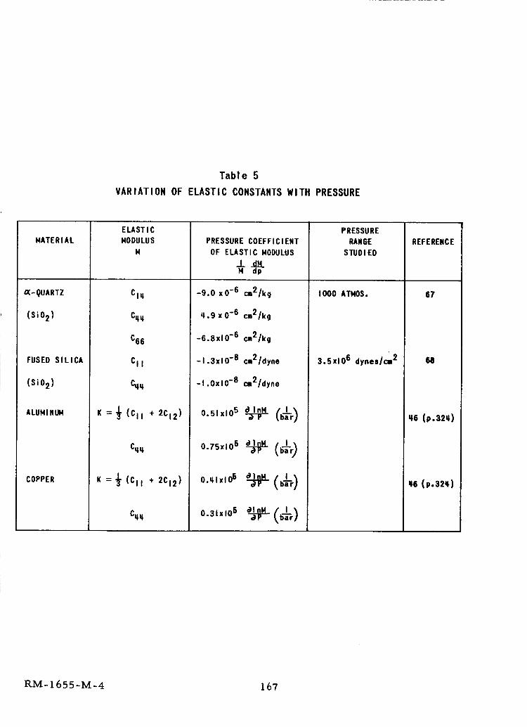
Tab1 e 5
VARIATION OF ELASTIC CONSTANTS WITH PRESSURE
MATERIAL
_-gUARTZ
(sio 2)
FUSED SILICA
(SiO 2)
ALUHINUM
COPPER
ELASTIC
MODULUS
M
CIq
Cztq
C66
CII
Cqzt
K =_ (CII + 2CI2 )
C_
K =_ (CII + 2CI2 )
Citq
PRESSURE COEFFICIENT
OF ELASTIC MODULUS
-9.0 xO -6 cm2/kg
_.9x0 -6 cm2/kg
-6.8x10 -6 cm2/kg
-I.3xlO -8 cm2/dyne
-I,OxlO -8 cm2/dyne
o_,_o__ C_'_)
o.,_x,o5._ (_÷r)
o.,,,x,o_._- (,,'r)
0"31x106 _ (b_-r)
PRESSURE
RANGE
STUDIED
I000 ATHOS.
3.5x10⁶ dynes/cm 2
REFERENCE
67
68
_6 (p.32q)
q6 (p.32q)
RM- 1655-M-4 167
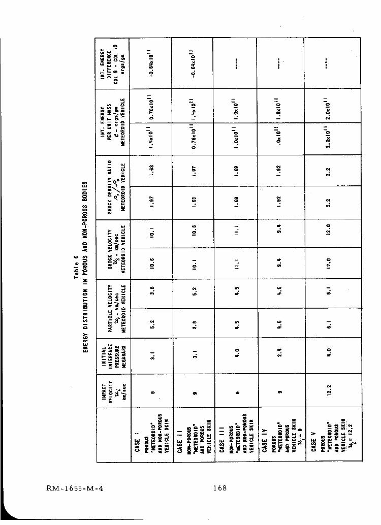
0
W
0
0
0a.I
Z0Z
Z
0
Z
Z0
l--cn
>-
Q_L_JZ
0
i!l 0o
IA'I I[ _/I I_
a. I--
0
X
I,.-
_ u m
m
0
o
x
o
o
#
o_
0
qD
0
t_
m
cI)
,Z0
)¢
qD
o
m
o
n
o
o
ot
o
o
4N
tn
io
c_
m
c_
0
-ii|
0
m
0
o_
o_c_
w
In
tn
0
CD
_o
4
0
0
U_
N
0
¢4
0
,4
c_
_4
0
0
0
=r
_4
RM-1655-M-4 168
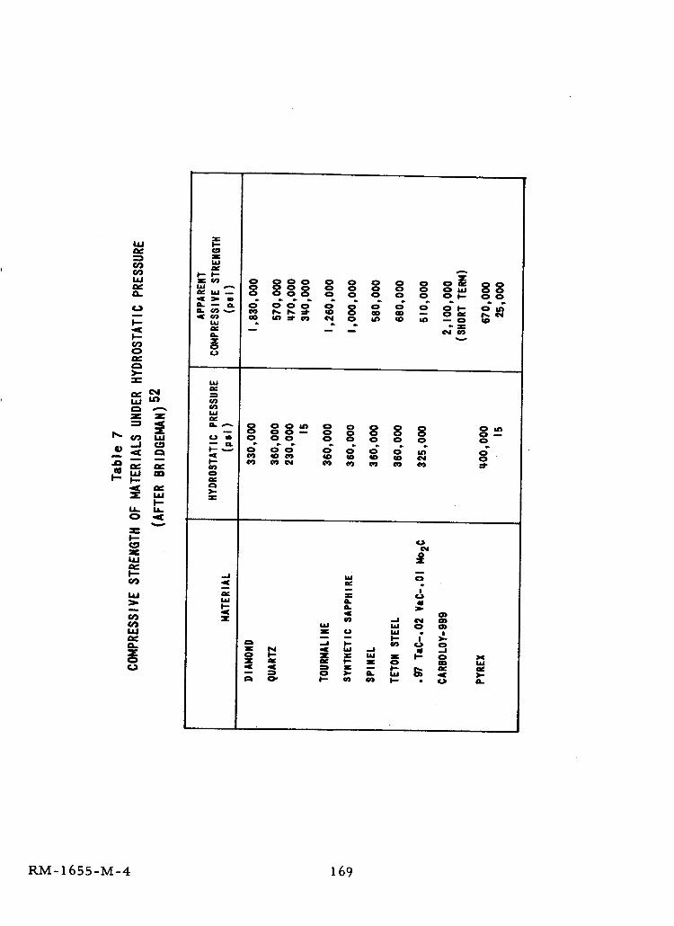
_ o _Oooo oO_ oOoo .°o- o oo o o o o o,- o
o_
z
_ w o_ - o o °o -o o o
_ o
u. u.
o_
o _ o _- _ _. _I- 4-J I-*
RM-1655-M-4 169
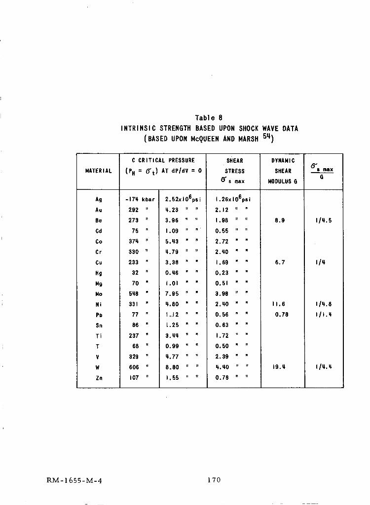
Table 8
INTRINSIC STRENGTH BASED UPON SHOCK WAVE DATA
(BASED UPON McQUEEN AND HARSH 5_)
14ATERIAL
Ag
Au
Be
Cd
Co
Cr
Cu
Hg
149
14o
Ni
Pe
Sn
Ti
T
V
W
Zn
C CRITICAL PRESSURE
(PH = O_t ) AT dP/dV = 0
-17_ kbar
292 "
273 "
75 "
371_ .
330 "
233 "
32 "
70 "
5t_8 "
331 "
77 "
86 "
237 "
68 "
329 "
606 "
107 "
2.52xlO6ps i
;.23 " "
3.96 " "
1.09 " "
5. u,3 " "
;.79 " "
3.38 " "
0._6 " "
I . 01 " "
7.95 " "
_. 80 " "
I. 12 ....
1.25 " "
3. _1_ " "
0.99 " "
II. 77 " "
8.80 " "
I. 55 " "
SHEAR
STRESS
_'6 max
I. 26x 106ps i
2.12 " "
I . 98 " "
O, 55 II .
2.72 " "
2. _0 " "
I . 69 " "
0.23 " "
0.51 " "
3.98 " "
2. I;O " "
0.56 " "
O. 63 " "
1.72 " "
O. 50 " "
2.39 " "
q'._0 " "
O. 78 " "
DYNA141C
SHEAR
140DULUSG
8.9
6,7
11,6
0.78
19.q,
_'_$ faSX
6
II_.5
_/_
il_._
RM-1655-M-4 170