Embed Size (px)
Citation preview
FINAL REPORT
LDDX: A High Efficiency Air Conditioner for DOD Buildings
ESTCP Project EW-201137
FEBRUARY 2017
Dr. Andrew Lowenstein AIL Research, Inc.
Distribution Statement A
This document has been cleared for public release

Page Intentionally Left Blank
This report was prepared under contract to the Department of Defense Environmental Security Technology Certification Program (ESTCP). The publication of this report does not indicate endorsement by the Department of Defense, nor should the contents be construed as reflecting the official policy or position of the Department of Defense. Reference herein to any specific commercial product, process, or service by trade name, trademark, manufacturer, or otherwise, does not necessarily constitute or imply its endorsement, recommendation, or favoring by the Department of Defense.

Page Intentionally Left Blank
REPORT DOCUMENTATION PAGE Form Approved OMB No. 0704-0188
Public reporting burden for this collection of information is estimated to average 1 hour per response, including the time for reviewing instructions, searching existing data sources, gathering and maintaining the data needed, and completing and reviewing this collection of information. Send comments regarding this burden estimate or any other aspect of this collection of information, including suggestions for reducing this burden to Department of Defense, Washington Headquarters Services, Directorate for Information Operations and Reports (0704-0188), 1215 Jefferson Davis Highway, Suite 1204, Arlington, VA 22202-4302. Respondents should be aware that notwithstanding any other provision of law, no person shall be subject to any penalty for failing to comply with a collection of information if it does not display a currently valid OMB control number. PLEASE DO NOT RETURN YOUR FORM TO THE ABOVE ADDRESS. 1. REPORT DATE (DD-MM-YYYY) 2. REPORT TYPE
Final Report3. DATES COVERED (From - To)March 2013 to June 2017
4. TITLE AND SUBTITLELDDX: A High-Efficiency Air Conditioner for DoD Buildings
5a. CONTRACT NUMBER W912HQ-13-C-0003 5b. GRANT NUMBER EW-201137 5c. PROGRAM ELEMENT NUMBER
6. AUTHOR(S)Andrew Lowenstein, Jeffrey A. Miller, Thomas Hermans
5d. PROJECT NUMBER
5e. TASK NUMBER
5f. WORK UNIT NUMBER
7. PERFORMING ORGANIZATION NAME(S) AND ADDRESS(ES)
8. PERFORMING ORGANIZATION REPORTNUMBER
AIL Research, Inc. 57 Hamilton Avenue Hopewell, NJ 08525
9. SPONSORING / MONITORING AGENCY NAME(S) AND ADDRESS(ES) 10. SPONSOR/MONITOR’S ACRONYM(S)
11. SPONSOR/MONITOR’S REPORTNUMBER(S)
12. DISTRIBUTION / AVAILABILITY STATEMENT
Approved for public release; distribution unlimited
13. SUPPLEMENTARY NOTES
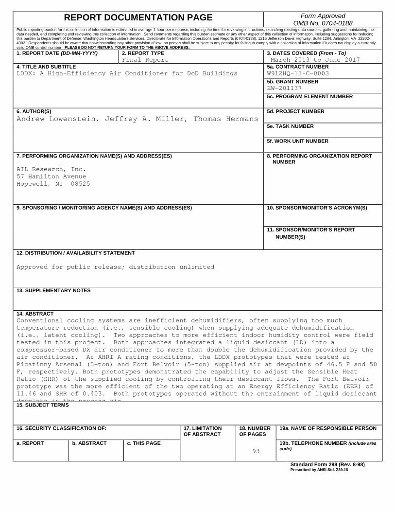
14. ABSTRACTConventional cooling systems are inefficient dehumidifiers, often supplying too much temperature reduction (i.e., sensible cooling) when supplying adequate dehumidification (i.e., latent cooling). Two approaches to more efficient indoor humidity control were field tested in this project. Both approaches integrated a liquid desiccant (LD) into a compressor-based DX air conditioner to more than double the dehumidification provided by the air conditioner. At AHRI A rating conditions, the LDDX prototypes that were tested at Picatinny Arsenal (3-ton) and Fort Belvoir (5-ton) supplied air at dewpoints of 46.5 F and 50 F, respectively. Both prototypes demonstrated the capability to adjust the Sensible Heat Ratio (SHR) of the supplied cooling by controlling their desiccant flows. The Fort Belvoir prototype was the more efficient of the two operating at an Energy Efficiency Ratio (EER) of 11.46 and SHR of 0.403. Both prototypes operated without the entrainment of liquid desiccant droplets in the process air15. SUBJECT TERMS
16. SECURITY CLASSIFICATION OF: 17. LIMITATIONOF ABSTRACT
18. NUMBEROF PAGES
19a. NAME OF RESPONSIBLE PERSON
a. REPORT b. ABSTRACT c. THIS PAGE93
19b. TELEPHONE NUMBER (include area code)
Standard Form 298 (Rev. 8-98) Prescribed by ANSI Std. Z39.18

Page Intentionally Left Blank

i
FINAL REPORT Project: EW-201137
TABLE OF CONTENTS
Page
EXECUTIVE SUMMARY ............................................................................................................ 1
1.0 INTRODUCTION ................................................................................................................. 1 1.1 BACKGROUND .......................................................................................................... 1 1.2 OBJECTIVE OF THE DEMONSTRATION ............................................................... 2
1.2.1 Validate .......................................................................................................................... 2 1.2.2 Findings and Guideline .................................................................................................. 2 1.2.3 Technology Transfer ...................................................................................................... 2 1.2.4 Acceptance ..................................................................................................................... 2 1.2.5 Additional Benefits ........................................................................................................ 3 1.2.6 Deliverables ................................................................................................................... 3
1.3 REGULATORY DRIVERS ......................................................................................... 3
2.0 TECHNOLOGY DESCRIPTION ......................................................................................... 5 2.1 TECHNOLOGY OVERVIEW ..................................................................................... 5
2.1.1 Description – LDDX-WF .............................................................................................. 5 2.1.2 Visual Depiction—LDDX-WF ...................................................................................... 8 2.1.3 Description – LDDX-Ad .............................................................................................. 11 2.1.4 Visual Depiction—LDDX-Ad ..................................................................................... 12 2.1.5 Comparison to Existing Technology ............................................................................ 15 2.1.6 Chronological Summary .............................................................................................. 16 2.1.7 Future Potential for DOD ............................................................................................. 16
2.2 TECHNOLOGY DEVELOPMENT ........................................................................... 17 2.3 ADVANTAGES AND LIMITATIONS OF THE TECHNOLOGY .......................... 17
3.0 PERFORMANCE OBJECTIVES ....................................................................................... 19 3.1 SUMMARY OF PERFORMANCE OBJECTIVES ................................................... 19 3.2 PERFORMANCE OBJECTIVES DESCRIPTIONS ................................................. 19
4.0 FACILITY/SITE DESCRIPTION ....................................................................................... 27 4.1 PICATINNY ARSENAL: FACILITY/SITE LOCATION AND OPERATIONS ..... 27 4.2 FORT BELVOIR: FACILITY/SITE LOCATION AND OPERATIONS ................. 28
5.0 TEST DESIGN .................................................................................................................... 31 5.1 CONCEPTUAL TEST DESIGN ................................................................................ 31
5.1.1 Independent variables .................................................................................................. 31 5.1.2 Dependent variable ...................................................................................................... 31 5.1.3 Test Design .................................................................................................................. 32 5.1.4 Test Phases ................................................................................................................... 33
TABLE OF CONTENTS (Continued)
Page
ii
5.1.5 Pre-set variables ........................................................................................................... 33 5.1.6 Uncontrolled variables ................................................................................................. 33 5.1.7 Dependent variable ...................................................................................................... 33 5.1.8 Test Design .................................................................................................................. 34 5.1.9 Test Phases ................................................................................................................... 34
5.2 BASELINE CHARACTERIZATION ........................................................................ 34 5.3 DESIGN AND LAYOUT OF SYSTEM COMPONENTS ........................................ 35 5.4 OPERATIONAL TESTING ....................................................................................... 37 5.5 SAMPLING PROTOCOL .......................................................................................... 38 5.6 EQUIPMENT CALIBRATION AND DATA QUALITY ISSUES .......................... 39
6.0 PERFORMANCE ASSESSMENT ..................................................................................... 41 6.1 LDDX-WF LABORATORY PERFORMANCE ....................................................... 41 6.2 LDDX-AD LABORATORY PERFORMANCE ....................................................... 45 6.3 LDDX-WF FIELD PERFORMANCE ....................................................................... 46 6.4 LDDX-AD FIELD PERFORMANCE ....................................................................... 50 6.5 MAINTENANCE ISSUES & PROTOTYPICAL DESIGN WEAKNESSES ........... 54
6.5.1 Picatinny Arsenal ......................................................................................................... 54 6.5.2 Fort Belvoir .................................................................................................................. 55
7.0 COST ASSESSMENT ......................................................................................................... 57 7.1 COST MODEL ........................................................................................................... 57
7.1.1 Space Conditioning for Comfort .................................................................................. 57 7.1.2 Solving Building Humidity Problems .......................................................................... 58 7.1.3 Mitigating Corrosion Damage of Stored Material ....................................................... 59
7.2 COST DRIVERS ........................................................................................................ 60 7.3 COST ANALYSIS AND COMPARISON ................................................................. 61
8.0 IMPLEMENTATION ISSUES ........................................................................................... 63
APPENDIX A POINTS OF CONTACT ................................................................................ A-1
iii
LIST OF FIGURES
Page
Figure 1. Wicking-Fin Heat and Mass Exchanger ...................................................................... 5 Figure 2. Wicking Fins Implemented with Corrugated Media ................................................... 6 Figure 3. Refrigerant and Desiccant Circuits for the LDDX ...................................................... 7 Figure 4. Engineering Drawing of the LDDX-WF Prototype .................................................... 9 Figure 5. Flow Diagram of the LDDX-Ad ............................................................................... 11 Figure 6. Engineering Drawing of the LDDX-Ad Prototype ................................................... 13 Figure 7. Map of the Test Site within the Picatinny Arsenal .................................................... 28 Figure 8. Site Map and Aerial View of Test Site at Fort Belvoir ............................................. 29 Figure 9. Flow Loop for Testing Prototype of 3-Ton LDDX ................................................... 32 Figure 10. Installation Sites: Fort Belvoir (left) and Picatinny Arsenal (right) .......................... 35 Figure 11. Installation of LDDX-WF in Parallel with Existing AC including Common T and rh
Instrumentation .......................................................................................................... 36 Figure 12. Installation of LDDX-Ad in Parallel with Existing AC Including Common T and rh
Instrumentation .......................................................................................................... 37 Figure 13. Sample Performance Data for Fort Belvoir LDDX, Sept 4, 2015 ............................ 39 Figure 14. Calibration of the Impellor-Based Air Flow Measurement ....................................... 40 Figure 15. Experimental Performance of the LDDX-WF at AHRI A Rating Conditions (EER is
based on compressor power only) ............................................................................. 41 Figure 16. Experimental Performance of the LDDX-WF at AHRI A Rating Conditions: Supply
Dewpoint and Relative Humidity .............................................................................. 42 Figure 17. Predicted EER for LDDX-WF with Larger Condenser and Evaporator ................... 44 Figure 18. Predicted Supply Dewpoint for LDDX-WF with Larger Condenser and Evaporator
................................................................................................................................... 44 Figure 19. The Laboratory Performance of the 5-Ton LDDX-Ad ............................................. 45 Figure 20. The Laboratory Performance of the 5-Ton LDDX-Ad ............................................. 46 Figure 21. The Installed LDDX-WF Prototype .......................................................................... 47 Figure 22. 2015 Seasonal Performance of the LDDX-WF Prototype ....................................... 49 Figure 23. The Impact of the LDDX-WF on Indoor RH ............................................................ 50 Figure 24. The Installed LDDX-Ad Prototype ........................................................................... 50 Figure 25. 2016 Seasonal Performance of the LDDX-Ad Prototype ......................................... 52 Figure 26. Supply Air Dewpoint with and without the Liquid- Desiccant Circuit Active ......... 53 Figure 27. Impact of Dry Supply Air on the Zone’s Relative Humidity .................................... 53 Figure 28. LDDX-Ad’s EER with and without the Liquid-Desiccant Circuit Active ................ 54
iv
LIST OF TABLES
Page
Table 1. Performance Objective – LDDX-WF ......................................................................... 20 Table 2. Performance Objectives – LDDX-Ad ......................................................................... 21 Table 3. Laboratory Test Runs of LDDX-Ad Prototype .......................................................... 48
v
ACRONYMS AND ABBREVIATIONS
AC Air Conditioner AHRI Air Conditioning, Heating and Refrigeration Institute AHMX Adiabatic Heat and Mass eXchanger AILR AIL Research Btu British Thermal Unit cfm cubic feet per minute COP Coefficient of Performance DOD Department of Defense DX Direct Expansion EER Energy Efficiency Ratio HVAC Heating, Ventilation and Air Conditioning IHX Interchange Heat Exchanger LD Liquid Desiccant LDDX Liquid Desiccant Direct Expansion AC LDDX-WF Liquid Desiccant Direct Expansion AC with WFHMX LDDX-Ad Liquid Desiccant Direct Expansion AC with AHMX LiCl Lithium Chloride LHR Latent Heat Ratio NVESD Night Vision and Electronic Sensors Directorate O&M Operating and Maintenance PEMS Picatinny Environmental Management System rh relative humidity SHR Sensible Heat Ratio TRL Technical Readiness Level WFHMX Wicking Fin Heat and Mass eXchanger

vi
Page Intentionally Left Blank
vii
ACKNOWLEDGEMENTS
The authors would like to thank the Department of Defense’s Environmental Security Technology Certification Program (ESTCP) project team members for their technical and administrative support in executing the project’s demonstration plan and the ESTCP program office for its financial support. We also thank Mr. William Elliott, Master Planner, Facilities and Energy at Fort Belvoir and Mr. Nicholas Stecky, Resource Efficiency Manager, at Picatinny Arsenal for the insight they provided in selecting test sites at their respective bases and the assistance they provided in planning the installation and operation of the prototypes. Ms. Gricel Rivera is also thanked for her assistance in coordinating activities at Picatinny Arsenal following the retirement of Mr. Stecky in 2016.

viii
Page Intentionally Left Blank
ES-1
EXECUTIVE SUMMARY
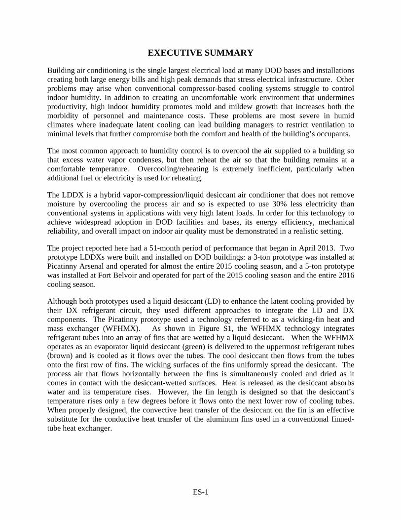
Building air conditioning is the single largest electrical load at many DOD bases and installations creating both large energy bills and high peak demands that stress electrical infrastructure. Other problems may arise when conventional compressor-based cooling systems struggle to control indoor humidity. In addition to creating an uncomfortable work environment that undermines productivity, high indoor humidity promotes mold and mildew growth that increases both the morbidity of personnel and maintenance costs. These problems are most severe in humid climates where inadequate latent cooling can lead building managers to restrict ventilation to minimal levels that further compromise both the comfort and health of the building’s occupants.
The most common approach to humidity control is to overcool the air supplied to a building so that excess water vapor condenses, but then reheat the air so that the building remains at a comfortable temperature. Overcooling/reheating is extremely inefficient, particularly when additional fuel or electricity is used for reheating.
The LDDX is a hybrid vapor-compression/liquid desiccant air conditioner that does not remove moisture by overcooling the process air and so is expected to use 30% less electricity than conventional systems in applications with very high latent loads. In order for this technology to achieve widespread adoption in DOD facilities and bases, its energy efficiency, mechanical reliability, and overall impact on indoor air quality must be demonstrated in a realistic setting.
The project reported here had a 51-month period of performance that began in April 2013. Two prototype LDDXs were built and installed on DOD buildings: a 3-ton prototype was installed at Picatinny Arsenal and operated for almost the entire 2015 cooling season, and a 5-ton prototype was installed at Fort Belvoir and operated for part of the 2015 cooling season and the entire 2016 cooling season.
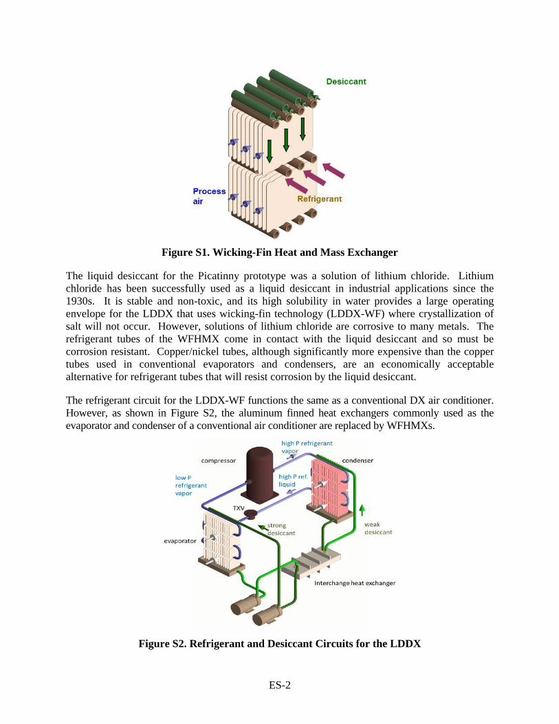
Although both prototypes used a liquid desiccant (LD) to enhance the latent cooling provided by their DX refrigerant circuit, they used different approaches to integrate the LD and DX components. The Picatinny prototype used a technology referred to as a wicking-fin heat and mass exchanger (WFHMX). As shown in Figure S1, the WFHMX technology integrates refrigerant tubes into an array of fins that are wetted by a liquid desiccant. When the WFHMX operates as an evaporator liquid desiccant (green) is delivered to the uppermost refrigerant tubes (brown) and is cooled as it flows over the tubes. The cool desiccant then flows from the tubes onto the first row of fins. The wicking surfaces of the fins uniformly spread the desiccant. The process air that flows horizontally between the fins is simultaneously cooled and dried as it comes in contact with the desiccant-wetted surfaces. Heat is released as the desiccant absorbs water and its temperature rises. However, the fin length is designed so that the desiccant’s temperature rises only a few degrees before it flows onto the next lower row of cooling tubes. When properly designed, the convective heat transfer of the desiccant on the fin is an effective substitute for the conductive heat transfer of the aluminum fins used in a conventional finned-tube heat exchanger.
ES-2
Figure S1. Wicking-Fin Heat and Mass Exchanger
The liquid desiccant for the Picatinny prototype was a solution of lithium chloride. Lithium chloride has been successfully used as a liquid desiccant in industrial applications since the 1930s. It is stable and non-toxic, and its high solubility in water provides a large operating envelope for the LDDX that uses wicking-fin technology (LDDX-WF) where crystallization of salt will not occur. However, solutions of lithium chloride are corrosive to many metals. The refrigerant tubes of the WFHMX come in contact with the liquid desiccant and so must be corrosion resistant. Copper/nickel tubes, although significantly more expensive than the copper tubes used in conventional evaporators and condensers, are an economically acceptable alternative for refrigerant tubes that will resist corrosion by the liquid desiccant.
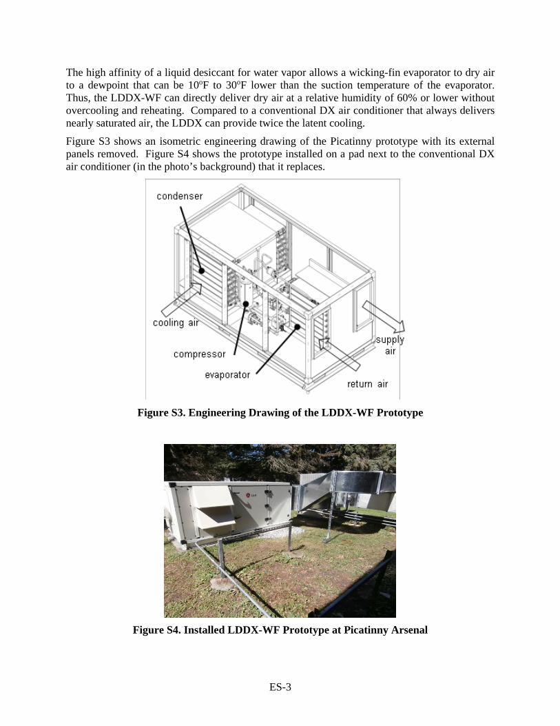
The refrigerant circuit for the LDDX-WF functions the same as a conventional DX air conditioner. However, as shown in Figure S2, the aluminum finned heat exchangers commonly used as the evaporator and condenser of a conventional air conditioner are replaced by WFHMXs.
Figure S2. Refrigerant and Desiccant Circuits for the LDDX
ES-3
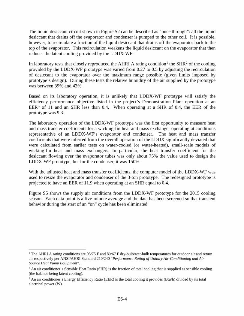
The high affinity of a liquid desiccant for water vapor allows a wicking-fin evaporator to dry air to a dewpoint that can be 10oF to 30oF lower than the suction temperature of the evaporator. Thus, the LDDX-WF can directly deliver dry air at a relative humidity of 60% or lower without overcooling and reheating. Compared to a conventional DX air conditioner that always delivers nearly saturated air, the LDDX can provide twice the latent cooling. Figure S3 shows an isometric engineering drawing of the Picatinny prototype with its external panels removed. Figure S4 shows the prototype installed on a pad next to the conventional DX air conditioner (in the photo’s background) that it replaces.
Figure S3. Engineering Drawing of the LDDX-WF Prototype
Figure S4. Installed LDDX-WF Prototype at Picatinny Arsenal
ES-4
The liquid desiccant circuit shown in Figure S2 can be described as “once through”: all the liquid desiccant that drains off the evaporator and condenser is pumped to the other coil. It is possible, however, to recirculate a fraction of the liquid desiccant that drains off the evaporator back to the top of the evaporator. This recirculation weakens the liquid desiccant on the evaporator that then reduces the latent cooling provided by the LDDX-WF.
In laboratory tests that closely reproduced the AHRI A rating condition1 the SHR2 of the cooling provided by the LDDX-WF prototype was varied from 0.27 to 0.5 by adjusting the recirculation of desiccant to the evaporator over the maximum range possible (given limits imposed by prototype’s design). During these tests the relative humidity of the air supplied by the prototype was between 39% and 43%.
Based on its laboratory operation, it is unlikely that LDDX-WF prototype will satisfy the efficiency performance objective listed in the project’s Demonstration Plan: operation at an EER3 of 11 and an SHR less than 0.4. When operating at a SHR of 0.4, the EER of the prototype was 9.3.
The laboratory operation of the LDDX-WF prototype was the first opportunity to measure heat and mass transfer coefficients for a wicking-fin heat and mass exchanger operating at conditions representative of an LDDX-WF’s evaporator and condenser. The heat and mass transfer coefficients that were inferred from the overall operation of the LDDX significantly deviated that were calculated from earlier tests on water-cooled (or water-heated), small-scale models of wicking-fin heat and mass exchangers. In particular, the heat transfer coefficient for the desiccant flowing over the evaporator tubes was only about 75% the value used to design the LDDX-WF prototype, but for the condenser, it was 150%.
With the adjusted heat and mass transfer coefficients, the computer model of the LDDX-WF was used to resize the evaporator and condenser of the 3-ton prototype. The redesigned prototype is projected to have an EER of 11.9 when operating at an SHR equal to 0.4.
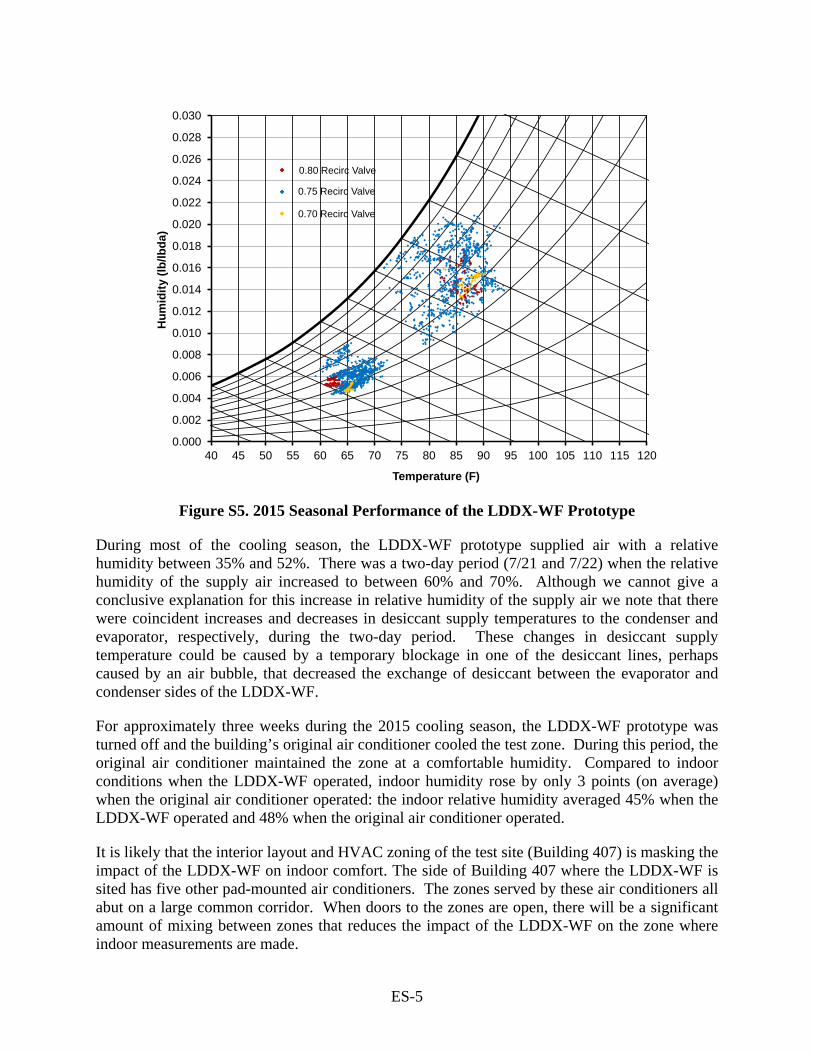
Figure S5 shows the supply air conditions from the LDDX-WF prototype for the 2015 cooling season. Each data point is a five-minute average and the data has been screened so that transient behavior during the start of an “on” cycle has been eliminated.
1 The AHRI A rating conditions are 95/75 F and 80/67 F dry-bulb/wet-bulb temperatures for outdoor air and return air respectively per ANSI/AHRI Standard 210/240 “Performance Rating of Unitary Air-Conditioning and Air-Source Heat Pump Equipment”. 2 An air conditioner’s Sensible Heat Ratio (SHR) is the fraction of total cooling that is supplied as sensible cooling (the balance being latent cooling). 3 An air conditioner’s Energy Efficiency Ratio (EER) is the total cooling it provides (Btu/h) divided by its total electrical power (W).
ES-5
0.80 Recirc Valve
0.75 Recirc Valve
0.70 Recirc Valve
0.000
0.002
0.004
0.006
0.008
0.010
0.012
0.014
0.016
0.018
0.020
0.022
0.024
0.026
0.028
0.030
40 45 50 55 60 65 70 75 80 85 90 95 100 105 110 115 120
Hum
idity
(lb/
lbda
)
Temperature (F)
Figure S5. 2015 Seasonal Performance of the LDDX-WF Prototype During most of the cooling season, the LDDX-WF prototype supplied air with a relative humidity between 35% and 52%. There was a two-day period (7/21 and 7/22) when the relative humidity of the supply air increased to between 60% and 70%. Although we cannot give a conclusive explanation for this increase in relative humidity of the supply air we note that there were coincident increases and decreases in desiccant supply temperatures to the condenser and evaporator, respectively, during the two-day period. These changes in desiccant supply temperature could be caused by a temporary blockage in one of the desiccant lines, perhaps caused by an air bubble, that decreased the exchange of desiccant between the evaporator and condenser sides of the LDDX-WF.
For approximately three weeks during the 2015 cooling season, the LDDX-WF prototype was turned off and the building’s original air conditioner cooled the test zone. During this period, the original air conditioner maintained the zone at a comfortable humidity. Compared to indoor conditions when the LDDX-WF operated, indoor humidity rose by only 3 points (on average) when the original air conditioner operated: the indoor relative humidity averaged 45% when the LDDX-WF operated and 48% when the original air conditioner operated.
It is likely that the interior layout and HVAC zoning of the test site (Building 407) is masking the impact of the LDDX-WF on indoor comfort. The side of Building 407 where the LDDX-WF is sited has five other pad-mounted air conditioners. The zones served by these air conditioners all abut on a large common corridor. When doors to the zones are open, there will be a significant amount of mixing between zones that reduces the impact of the LDDX-WF on the zone where indoor measurements are made.

ES-6
The degree to which the LDDX-WF prototype met the project’s original performance objectives is summarized in Table S1.
Table S1. Performance Objective Outcomes – LDDX-WF
Performance Objective Success Criteria Results
Supply of Dry Air Supply dewpoint less than 47 F at AHRI 210/240 rating conditions: 80/67 F DB/WB indoor 95/75 F DB/WB outdoor
Supply dewpoint equaled 46.5 F at AHRI 210/240 rating conditions
Minimum Supply Sensible Heat Ratio (SHR)
SHR equal to 0.35 or lower SHR equaled 0.275 at AHRI 210/240 rating conditions
Variable Supply Sensible Heat Ratio (SHR)
Supply SHR adjustable within 0.35 to 0.65 range
Supply SHR adjustable within 0.28 to 0.5 range
Energy Use for Total Cooling
EER over 11.0 while operating with SHR below 0.4; 30% savings relative to overcool/reheat AC at same SHR
12.0 EER at 0.4 SHR (projected performance for redesigned unit)
Direct Greenhouse Gas Emissions
20% reduction in emissions linked to building’s cooling system based on complete cooling season
20% reduction in emissions projected in some applications
User Satisfaction Acceptance of LDDX as indicated by an average user satisfaction that is more positive than a “neutral” response
User satisfaction could not be meaningfully assessed
O&M Characteristics Acceptance of LDDX Not studied; LDDX serviced only by AILR technician
The 5-ton LDDX prototype that was tested at Fort Belvoir used a technology referred to as adiabatic heat and mass exchangers (AHMX). This technology leads to a high latent air conditioner that is a simple, straightforward modification to a compressor-based DX air conditioner. Its enhanced dehumidification relies on a fundamental property of all desiccants: the amount of water they absorb depends on the surrounding air’s relative humidity (rh). For a DX air conditioner, the process air leaving the evaporator (Point A in Figure S6) is close to 100% rh while the cooling air leaving the condenser (Point B) will typically be less than 50% rh. A desiccant, either solid or liquid, that is alternately exposed to these two air streams will “pump” water from the high to the low relative humidity air stream. The heat that is released when the desiccant absorbs water is returned to the process air. The net result is that an LDDX with AHMXs (LDDX-Ad) supplies air with a relative humidity close to 50% and a temperature that is typically 20oF higher than its dewpoint temperature.
As shown in the flow diagram of Figure S6, two porous pads (i.e., adiabatic heat and mass exchangers: AHMXs)—one an absorber and the other a desorber—that are wetted with a liquid desiccant, move moisture from the process air to the cooling air. The pressure drop through the desiccant-wetted pads is very small—typically less than 0.1 inch w.c.—and the pumps are low wattage so the power to run the LDDX-Ad is essentially the same as that for its embedded DX system. There is a slight loss of total cooling caused by the warm desiccant that flows onto the absorber, but this loss in total cooling is small, typically on the order of 5%.

ES-7
Figure S6. Flow Diagram of the LDDX-Ad
The LDDX-Ad can adjust its Sensible Heat Ratio so that it can independently control indoor temperature and humidity. When the pumps are turned off, the LDDX-Ad reverts to a conventional DX AC with a high SHR—typically 0.75 or higher. With full desiccant flow, the LDDX-Ad’s SHR drops to 0.4. By modulating the desiccant flow, the LDDX’s SHR can be adjusted between these two limits. This modulation provides independent control of indoor temperature and humidity.
Unlike the LDDX-WF, the LDDX-Ad can operate with its desiccant circuit inactive. Under conditions that might lead to the over concentration of the liquid desiccant (i.e., low latent loads and low ambient humidity), the LDDX-Ad can revert to a conventional DX. This flexibility relaxes the need to operate with lithium chloride.
Although not as strong a desiccant as lithium chloride, potassium acetate has the advantage of being much less corrosive. A saturated solution of potassium acetate will be in equilibrium with air at 23% rh (versus 11% rh for a saturated solution of lithium chloride). This equilibrium relative humidity is sufficiently low to meet the requirements of the LDDX-Ad. Whereas the LDDX-Ad prototype used both lithium chloride and potassium acetate during laboratory tests, all field testing was done with potassium acetate. In June 2015, the 5-ton LDDX-Ad prototype was installed in the laboratory test loop where its performance was studied over a three-week test period. Tests were performed under varied condi-tions that included: (1) two different liquid desiccants (i.e., lithium chloride and potassium acetate), (2) a nominal and a twice nominal desiccant flow rate, and (3) a pulsed desiccant flow rate. The red crosses in Figure S7 are the values of SHR and EER for eight runs that had outdoor air temperatures close to AHRI rating temperature of 95 F. However, since the flow loop for the laboratory tests could not precisely maintain the AHRI A rating conditions, there is a moderate amount of scatter in the data shown in Figure S7. Using a computer model of the LDDX-Ad that closely matched the measured performance of the eight runs shown in Figure S7 the LDDX-Ad was predicted to have an SHR of 0.403 and an EER of 11.46 at the AHRI A rating condition. This predicted value appears as the red circle in Figure S7.

ES-8
0.35
0.40
0.45
0.50
0.55
0.60
0.65
0.70
0.75
0.80
5.0 7.0 9.0 11.0 13.0 15.0
SHR
EER
DX no reheat
reheat (Manufacturer 1)
reheat (Manufacturer 2)
LDDX modeled as-built
LDDX Test Data
conventional DX with increasing reheat
ARI A Operating Conditions
Figure S7. The Laboratory Performance of the 5-Ton LDDX-Ad
Figure S7 also includes EER/SHR data points for (1) a conventional high efficiency DX air conditioner (12.0/0.76), (2) a DX air conditioner with a low level of reheat (9.29/0.63), and a DX air conditioner with a high level of reheat (5.79/0.45). The LDDX-Ad’s ability to efficiently supply latent cooling is apparent when compared to both DX air conditioners that reheat the process air.
The effect that desiccant flow rate has on the SHR of the LDDX-Ad was explored in a second set of tests in which the flow of desiccant was pulsed on/off with a duty cycle (i.e., fraction time on) for desiccant delivery that varied from 0.09 to 1.0. In these tests the SHR for the delivered cooling varied from 0.42 at continuous desiccant flow to 0.62 at the lowest duty cycle. Since the SHR for the LDDX-Ad when the desiccant was turned off and the conditions of the supply air reached steady state was 0.79, the LDDX-Ad should have a controllable SHR up to this limiting value when operating at close to the AHRI A rating condition.
The LDDX-Ad prototype was shipped to Fort Belvoir on 8/17/15 and installed the next day as a replacement for a 4.5-ton heat pump that was near the end of its useful service life. A photo-graph of the installed prototype appears in Figure S8. The prototype operated for several weeks in 2015, but operation was suspended when the desorbing AHMX behind the condenser failed.
Figure S8. The Installed LDDX-Ad Prototype
ES-9
During the 2015/2016 winter, work was performed to correct the problem that led to the failure of the LDDX-Ad’s desorbing AHMX. The source of the problem was an incompatibility between the corrugated fiberglass contact media used in the AHMX and the solution of potassium acetate. An inspection of the failed AHMX showed that the potassium acetate was dissolving/attacking the binder used for the fiberglass and softening the pad.
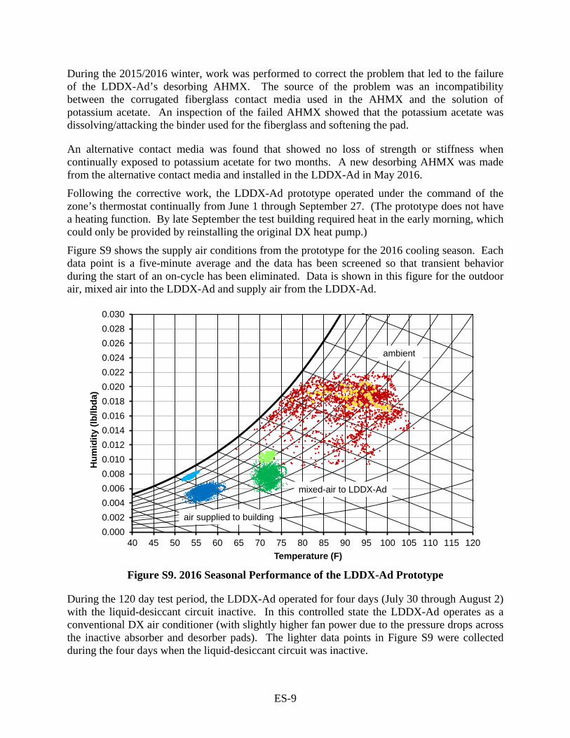
An alternative contact media was found that showed no loss of strength or stiffness when continually exposed to potassium acetate for two months. A new desorbing AHMX was made from the alternative contact media and installed in the LDDX-Ad in May 2016. Following the corrective work, the LDDX-Ad prototype operated under the command of the zone’s thermostat continually from June 1 through September 27. (The prototype does not have a heating function. By late September the test building required heat in the early morning, which could only be provided by reinstalling the original DX heat pump.) Figure S9 shows the supply air conditions from the prototype for the 2016 cooling season. Each data point is a five-minute average and the data has been screened so that transient behavior during the start of an on-cycle has been eliminated. Data is shown in this figure for the outdoor air, mixed air into the LDDX-Ad and supply air from the LDDX-Ad.
0.0000.0020.0040.0060.0080.0100.0120.0140.0160.0180.0200.0220.0240.0260.0280.030
40 45 50 55 60 65 70 75 80 85 90 95 100 105 110 115 120
Hum
idity
(lb/
lbda
)
Temperature (F)
mixed-air to LDDX-Ad
air supplied to building
ambient
Figure S9. 2016 Seasonal Performance of the LDDX-Ad Prototype
During the 120 day test period, the LDDX-Ad operated for four days (July 30 through August 2) with the liquid-desiccant circuit inactive. In this controlled state the LDDX-Ad operates as a conventional DX air conditioner (with slightly higher fan power due to the pressure drops across the inactive absorber and desorber pads). The lighter data points in Figure S9 were collected during the four days when the liquid-desiccant circuit was inactive.

ES-10
With the liquid-desiccant circuit active, the LDDX-Ad supplied air with a relative humidity between 42% and 70%; with the circuit inactive, it supplied air with a relative humidity centered on 90%. With the liquid-desiccant circuit active, the average dewpoint of the supply air increased from 40oF to 43oF as the ambient humidity increased from 28% to near 100%. This behavior is expected since desiccant regeneration by the condenser/desorber becomes less effective as ambient relative humidity increases. With the liquid-desiccant circuit inactive, the supply-air dewpoint was closer to 50oF. Figure S10 shows the impact of the drier supply air on the zone’s relative humidity. With the liquid-desiccant circuit active, the zone relative humidity trended between 40% and 45%. With the circuit inactive, zone relative humidity was in the range of 55% to 60%.
20
25
30
35
40
45
50
55
60
65
70
0 20 40 60 80 100
Indo
orR
H
Outdoor Relative Humidity
des off Aug 2016des on July 2016des on Aug 2016
Figure S10. The Impact of Dry Supply Air on the Zone Relative Humidity
As noted earlier, an active liquid-desiccant circuit does penalize efficiency by transferring heat rejected by the condenser to the supply air. A computer model of the LDDX-Ad predicts about a 5% drop in EER due to “heat dump” under conditions typical of operation at Fort Belvoir. However, the performance data collected during the field test showed about a 15% drop in EER when the LDDX-Ad’s liquid-desiccant circuit was active. This larger drop in efficiency is due to the fact that with the liquid-desiccant circuit active the room humidity decreases as does the return air that the LDDX-Ad processes. With drier, lower enthalpy air entering the evaporator, the suction temperature of the refrigerant circuit decreases and the compressor power increases. Test data showed that the LDDX-Ad with an active liquid-desiccant circuit had a suction temperature that was about 3.5oF lower than when the circuit is inactive. This drop in suction temperature accounts for about half of the 15% drop in EER.
ES-11
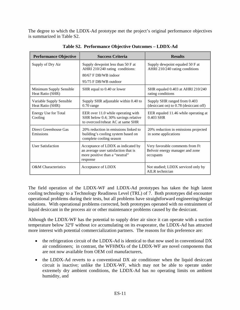
The degree to which the LDDX-Ad prototype met the project’s original performance objectives is summarized in Table S2.
Table S2. Performance Objective Outcomes – LDDX-Ad
Performance Objective Success Criteria Results
Supply of Dry Air Supply dewpoint less than 50 F at AHRI 210/240 rating conditions: 80/67 F DB/WB indoor 95/75 F DB/WB outdoor
Supply dewpoint equaled 50 F at AHRI 210/240 rating conditions
Minimum Supply Sensible Heat Ratio (SHR)
SHR equal to 0.40 or lower SHR equaled 0.403 at AHRI 210/240 rating conditions
Variable Supply Sensible Heat Ratio (SHR)
Supply SHR adjustable within 0.40 to 0.70 range
Supply SHR ranged from 0.403 (desiccant on) to 0.78 (desiccant off)
Energy Use for Total Cooling
EER over 11.0 while operating with SHR below 0.4; 30% savings relative to overcool/reheat AC at same SHR
EER equaled 11.46 while operating at 0.403 SHR
Direct Greenhouse Gas Emissions
20% reduction in emissions linked to building’s cooling system based on complete cooling season
20% reduction in emissions projected in some applications
User Satisfaction Acceptance of LDDX as indicated by an average user satisfaction that is more positive than a “neutral” response
Very favorable comments from Ft Belvoir energy manager and zone occupants
O&M Characteristics Acceptance of LDDX Not studied; LDDX serviced only by AILR technician
The field operation of the LDDX-WF and LDDX-Ad prototypes has taken the high latent cooling technology to a Technology Readiness Level (TRL) of 7. Both prototypes did encounter operational problems during their tests, but all problems have straightforward engineering/design solutions. With operational problems corrected, both prototypes operated with no entrainment of liquid desiccant in the process air or other maintenance problems caused by the desiccant.
Although the LDDX-WF has the potential to supply drier air since it can operate with a suction temperature below 32oF without ice accumulating on its evaporator, the LDDX-Ad has attracted more interest with potential commercialization partners. The reasons for this preference are:
• the refrigeration circuit of the LDDX-Ad is identical to that now used in conventional DX air conditioners; in contrast, the WFHMXs of the LDDX-WF are novel components that are not now available from OEM coil manufacturers,
• the LDDX-Ad reverts to a conventional DX air conditioner when the liquid desiccant circuit is inactive; unlike the LDDX-WF, which may not be able to operate under extremely dry ambient conditions, the LDDX-Ad has no operating limits on ambient humidity, and
ES-12
• the LDDX-Ad can operate with desiccants that are less corrosive than the lithium chloride that is required by the LDDX-WF
Compared to alternative technologies for enhancing the latent cooling provided by an air conditioner, the LDDX-Ad could become the option with the lowest capital cost. The two alternatives now commercially available are (1) DX air conditioners with reheat provided by recovered heat from the condenser, and (2) DX air conditioners that use solid desiccant rotors to augment their latent cooling (SDDX).
As previously noted, air conditioners that overcool the process air to remove moisture and then flow the cooled air over a secondary indoor condenser so that the air is reheated are inherently inefficient since a large fraction of the cooling provided by the compressor is undone by the reheat. But not only are condenser-reheat air conditioners inefficient, they are expensive when their cost is based on the cooling they provide when reheat is active. In applications where the capacity of the cooling system is based on loads and performance on a dehumidification (i.e., dewpoint) design day the installed gross capacity of a DX air conditioner that uses condenser reheat might be 30% higher than the total load on the dehumidification design day.
An LDDX-Ad that competes with the condenser-reheat system may be the lower cost option—at least it may be the lower cost option once the technology matures and it is produced in high volumes. Since the liquid desiccant circuit only degrades total cooling capacity by about 5%, the LDDX-Ad’s refrigeration circuit will be approximately 25% smaller compared to a condenser-reheat system that provides the same net cooling. The liquid desiccant components that are an integral part of the LDDX-Ad are relatively simple and low cost: a small pump, two AHMXs made from standard corrugated, fiberglass media (which is now used in evaporative coolers), plastic sumps and potassium acetate as the liquid desiccant. A 25% reduction in the refrigeration system might more than compensate for the cost of the LDDX-Ad’s liquid-desiccant circuit.
The LDDX-Ad will also be more efficient and less expensive than a DX air conditioner that uses a solid-desiccant rotor to augment its latent cooling. These solid-desiccant DX air conditioners are more efficient at moisture removal than their condenser-reheat counterparts, but they are more expensive.
The LDDX-Ad will have several performance and cost advantages compared to the SDDX:
• Air-side pressure drops through the LDDX-Ad’s AHMXs are much lower than those through the solid-desiccant rotor, leading to lower requirements for fan power.
• An LDDX-Ad can use a liquid-to-liquid heat exchanger to minimize the “heat dump” from warm, concentrated desiccant flowing to the process side of the unit; there is no equally effective way to reduce “heat dump” in an SDDX.
• A solid-desiccant rotor imposes geometrical constraints on the ducting of the regeneration air and the process air through the SDDX; these constraints increase the complexity and cost of the SDDX.
It is likely that early sales to DOD of the LDDX will not be driven solely by the need for improved indoor comfort (i.e., the option to allow indoor workspaces to float at a relative humidity at or above the ASHRAE-defined comfort range will always be the lowest cost option).
ES-13
However, when high indoor humidity leads to building maintenance problems associated with mold and mildew or when high indoor humidity adversely affects the operation of a laboratory, then an investment in the LDDX can be justified.
Perhaps the most important, broad driver for the adoption of the LDDX by DOD will be the need to control corrosion by storing material in drier environments. In this application, it is likely that the first cost and operating cost for the LDDX will be small compared to the reduced maintenance needs or the economic impact of failures in sensitive avionics caused by corrosion

ES-14
Page Intentionally Left Blank
1
1.0 INTRODUCTION
1.1 BACKGROUND
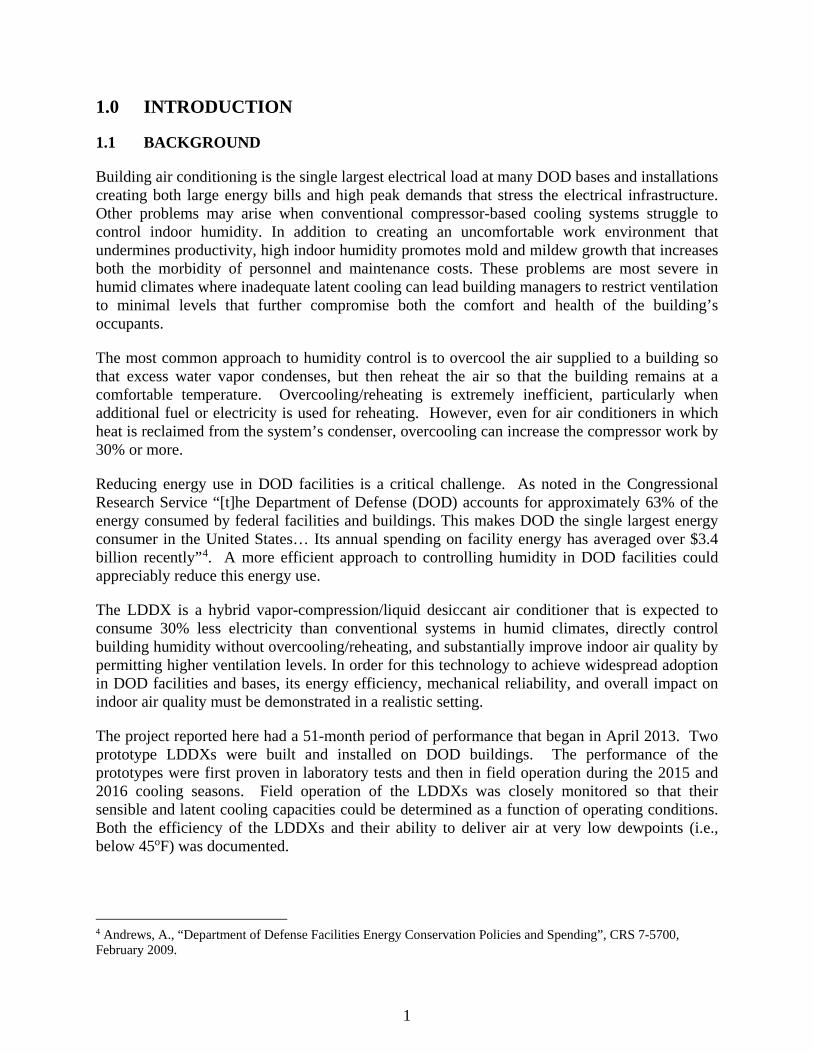
Building air conditioning is the single largest electrical load at many DOD bases and installations creating both large energy bills and high peak demands that stress the electrical infrastructure. Other problems may arise when conventional compressor-based cooling systems struggle to control indoor humidity. In addition to creating an uncomfortable work environment that undermines productivity, high indoor humidity promotes mold and mildew growth that increases both the morbidity of personnel and maintenance costs. These problems are most severe in humid climates where inadequate latent cooling can lead building managers to restrict ventilation to minimal levels that further compromise both the comfort and health of the building’s occupants.
The most common approach to humidity control is to overcool the air supplied to a building so that excess water vapor condenses, but then reheat the air so that the building remains at a comfortable temperature. Overcooling/reheating is extremely inefficient, particularly when additional fuel or electricity is used for reheating. However, even for air conditioners in which heat is reclaimed from the system’s condenser, overcooling can increase the compressor work by 30% or more.
Reducing energy use in DOD facilities is a critical challenge. As noted in the Congressional Research Service “[t]he Department of Defense (DOD) accounts for approximately 63% of the energy consumed by federal facilities and buildings. This makes DOD the single largest energy consumer in the United States… Its annual spending on facility energy has averaged over $3.4 billion recently”4. A more efficient approach to controlling humidity in DOD facilities could appreciably reduce this energy use.
The LDDX is a hybrid vapor-compression/liquid desiccant air conditioner that is expected to consume 30% less electricity than conventional systems in humid climates, directly control building humidity without overcooling/reheating, and substantially improve indoor air quality by permitting higher ventilation levels. In order for this technology to achieve widespread adoption in DOD facilities and bases, its energy efficiency, mechanical reliability, and overall impact on indoor air quality must be demonstrated in a realistic setting.
The project reported here had a 51-month period of performance that began in April 2013. Two prototype LDDXs were built and installed on DOD buildings. The performance of the prototypes were first proven in laboratory tests and then in field operation during the 2015 and 2016 cooling seasons. Field operation of the LDDXs was closely monitored so that their sensible and latent cooling capacities could be determined as a function of operating conditions. Both the efficiency of the LDDXs and their ability to deliver air at very low dewpoints (i.e., below 45oF) was documented.
4 Andrews, A., “Department of Defense Facilities Energy Conservation Policies and Spending”, CRS 7-5700, February 2009.
2
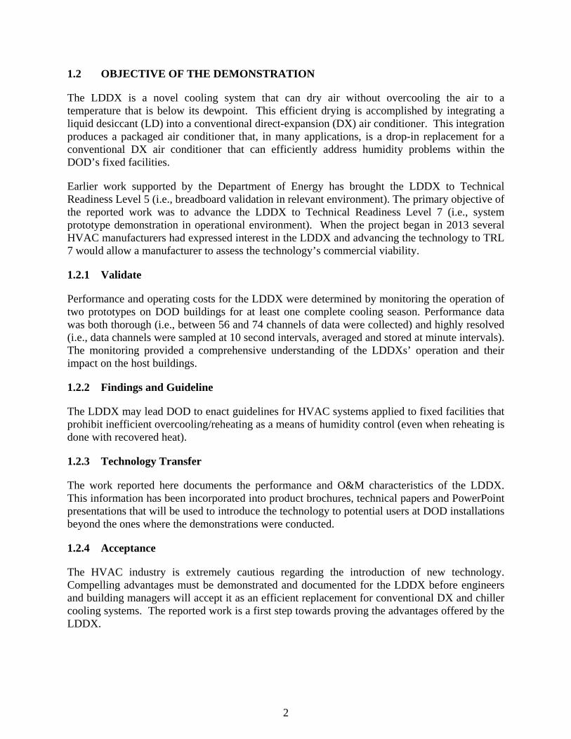
1.2 OBJECTIVE OF THE DEMONSTRATION
The LDDX is a novel cooling system that can dry air without overcooling the air to a temperature that is below its dewpoint. This efficient drying is accomplished by integrating a liquid desiccant (LD) into a conventional direct-expansion (DX) air conditioner. This integration produces a packaged air conditioner that, in many applications, is a drop-in replacement for a conventional DX air conditioner that can efficiently address humidity problems within the DOD’s fixed facilities.
Earlier work supported by the Department of Energy has brought the LDDX to Technical Readiness Level 5 (i.e., breadboard validation in relevant environment). The primary objective of the reported work was to advance the LDDX to Technical Readiness Level 7 (i.e., system prototype demonstration in operational environment). When the project began in 2013 several HVAC manufacturers had expressed interest in the LDDX and advancing the technology to TRL 7 would allow a manufacturer to assess the technology’s commercial viability.
1.2.1 Validate
Performance and operating costs for the LDDX were determined by monitoring the operation of two prototypes on DOD buildings for at least one complete cooling season. Performance data was both thorough (i.e., between 56 and 74 channels of data were collected) and highly resolved (i.e., data channels were sampled at 10 second intervals, averaged and stored at minute intervals). The monitoring provided a comprehensive understanding of the LDDXs’ operation and their impact on the host buildings.
1.2.2 Findings and Guideline
The LDDX may lead DOD to enact guidelines for HVAC systems applied to fixed facilities that prohibit inefficient overcooling/reheating as a means of humidity control (even when reheating is done with recovered heat).
1.2.3 Technology Transfer
The work reported here documents the performance and O&M characteristics of the LDDX. This information has been incorporated into product brochures, technical papers and PowerPoint presentations that will be used to introduce the technology to potential users at DOD installations beyond the ones where the demonstrations were conducted.
1.2.4 Acceptance
The HVAC industry is extremely cautious regarding the introduction of new technology. Compelling advantages must be demonstrated and documented for the LDDX before engineers and building managers will accept it as an efficient replacement for conventional DX and chiller cooling systems. The reported work is a first step towards proving the advantages offered by the LDDX.
3
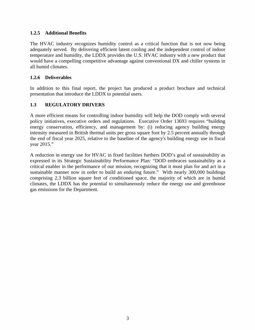
1.2.5 Additional Benefits
The HVAC industry recognizes humidity control as a critical function that is not now being adequately served. By delivering efficient latent cooling and the independent control of indoor temperature and humidity, the LDDX provides the U.S. HVAC industry with a new product that would have a compelling competitive advantage against conventional DX and chiller systems in all humid climates.
1.2.6 Deliverables
In addition to this final report, the project has produced a product brochure and technical presentation that introduce the LDDX to potential users.
1.3 REGULATORY DRIVERS
A more efficient means for controlling indoor humidity will help the DOD comply with several policy initiatives, executive orders and regulations. Executive Order 13693 requires “building energy conservation, efficiency, and management by: (i) reducing agency building energy intensity measured in British thermal units per gross square foot by 2.5 percent annually through the end of fiscal year 2025, relative to the baseline of the agency's building energy use in fiscal year 2015.”
A reduction in energy use for HVAC in fixed facilities furthers DOD’s goal of sustainability as expressed in its Strategic Sustainability Performance Plan: “DOD embraces sustainability as a critical enabler in the performance of our mission, recognizing that it must plan for and act in a sustainable manner now in order to build an enduring future.” With nearly 300,000 buildings comprising 2.3 billion square feet of conditioned space, the majority of which are in humid climates, the LDDX has the potential to simultaneously reduce the energy use and greenhouse gas emissions for the Department.

4
Page Intentionally Left Blank
5
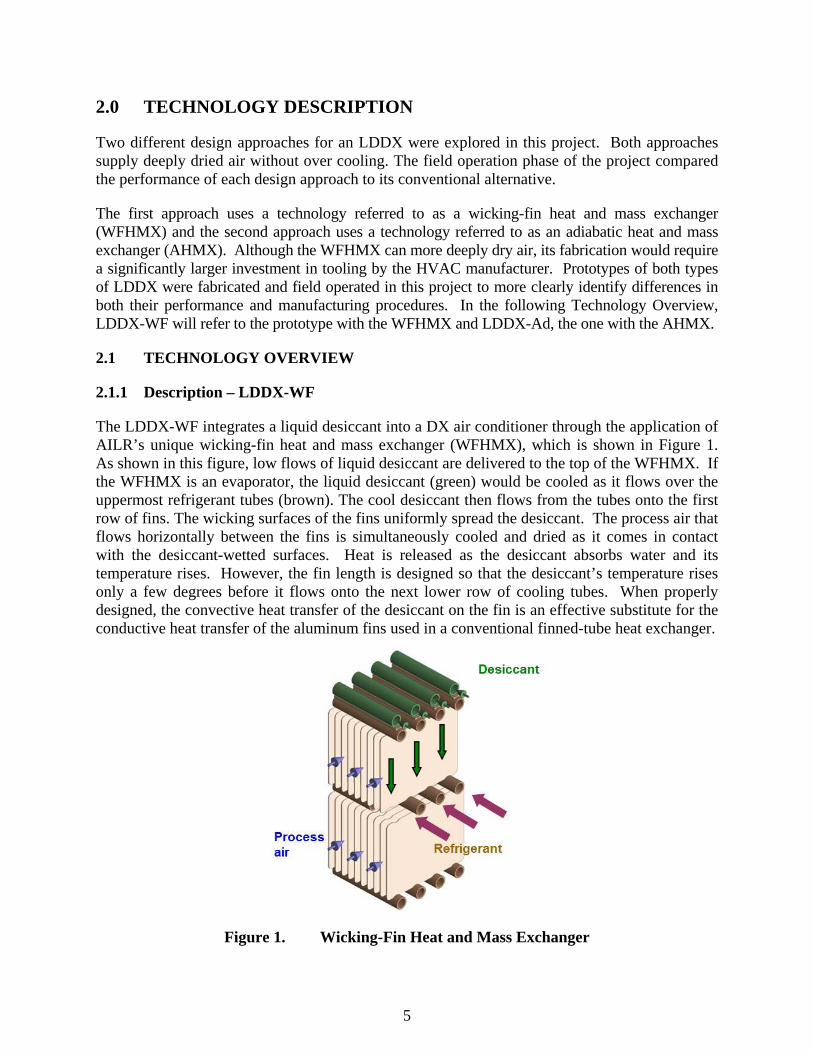
2.0 TECHNOLOGY DESCRIPTION
Two different design approaches for an LDDX were explored in this project. Both approaches supply deeply dried air without over cooling. The field operation phase of the project compared the performance of each design approach to its conventional alternative.
The first approach uses a technology referred to as a wicking-fin heat and mass exchanger (WFHMX) and the second approach uses a technology referred to as an adiabatic heat and mass exchanger (AHMX). Although the WFHMX can more deeply dry air, its fabrication would require a significantly larger investment in tooling by the HVAC manufacturer. Prototypes of both types of LDDX were fabricated and field operated in this project to more clearly identify differences in both their performance and manufacturing procedures. In the following Technology Overview, LDDX-WF will refer to the prototype with the WFHMX and LDDX-Ad, the one with the AHMX.
2.1 TECHNOLOGY OVERVIEW
2.1.1 Description – LDDX-WF
The LDDX-WF integrates a liquid desiccant into a DX air conditioner through the application of AILR’s unique wicking-fin heat and mass exchanger (WFHMX), which is shown in Figure 1. As shown in this figure, low flows of liquid desiccant are delivered to the top of the WFHMX. If the WFHMX is an evaporator, the liquid desiccant (green) would be cooled as it flows over the uppermost refrigerant tubes (brown). The cool desiccant then flows from the tubes onto the first row of fins. The wicking surfaces of the fins uniformly spread the desiccant. The process air that flows horizontally between the fins is simultaneously cooled and dried as it comes in contact with the desiccant-wetted surfaces. Heat is released as the desiccant absorbs water and its temperature rises. However, the fin length is designed so that the desiccant’s temperature rises only a few degrees before it flows onto the next lower row of cooling tubes. When properly designed, the convective heat transfer of the desiccant on the fin is an effective substitute for the conductive heat transfer of the aluminum fins used in a conventional finned-tube heat exchanger.
Figure 1. Wicking-Fin Heat and Mass Exchanger
6
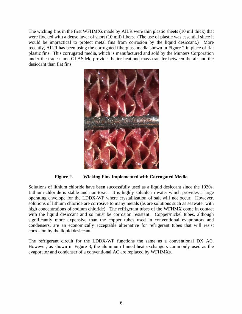
The wicking fins in the first WFHMXs made by AILR were thin plastic sheets (10 mil thick) that were flocked with a dense layer of short (10 mil) fibers. (The use of plastic was essential since it would be impractical to protect metal fins from corrosion by the liquid desiccant.) More recently, AILR has been using the corrugated fiberglass media shown in Figure 2 in place of flat plastic fins. This corrugated media, which is manufactured and sold by the Munters Corporation under the trade name GLASdek, provides better heat and mass transfer between the air and the desiccant than flat fins.
Figure 2. Wicking Fins Implemented with Corrugated Media
Solutions of lithium chloride have been successfully used as a liquid desiccant since the 1930s. Lithium chloride is stable and non-toxic. It is highly soluble in water which provides a large operating envelope for the LDDX-WF where crystallization of salt will not occur. However, solutions of lithium chloride are corrosive to many metals (as are solutions such as seawater with high concentrations of sodium chloride). The refrigerant tubes of the WFHMX come in contact with the liquid desiccant and so must be corrosion resistant. Copper/nickel tubes, although significantly more expensive than the copper tubes used in conventional evaporators and condensers, are an economically acceptable alternative for refrigerant tubes that will resist corrosion by the liquid desiccant.
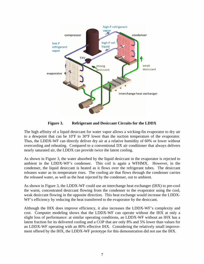
The refrigerant circuit for the LDDX-WF functions the same as a conventional DX AC. However, as shown in Figure 3, the aluminum finned heat exchangers commonly used as the evaporator and condenser of a conventional AC are replaced by WFHMXs.
7
Figure 3. Refrigerant and Desiccant Circuits for the LDDX
The high affinity of a liquid desiccant for water vapor allows a wicking-fin evaporator to dry air to a dewpoint that can be 10oF to 30oF lower than the suction temperature of the evaporator. Thus, the LDDX-WF can directly deliver dry air at a relative humidity of 60% or lower without overcooling and reheating. Compared to a conventional DX air conditioner that always delivers nearly saturated air, the LDDX can provide twice the latent cooling.
As shown in Figure 3, the water absorbed by the liquid desiccant in the evaporator is rejected to ambient in the LDDX-WF’s condenser. This coil is again a WFHMX. However, in the condenser, the liquid desiccant is heated as it flows over the refrigerant tubes. The desiccant releases water as its temperature rises. The cooling air that flows through the condenser carries the released water, as well as the heat rejected by the condenser, out to ambient.
As shown in Figure 3, the LDDX-WF could use an interchange heat exchanger (IHX) to pre-cool the warm, concentrated desiccant flowing from the condenser to the evaporator using the cool, weak desiccant flowing in the opposite direction. This heat exchange would increase the LDDX-WF’s efficiency by reducing the heat transferred to the evaporator by the desiccant.
Although the IHX does improve efficiency, it also increases the LDDX-WF’s complexity and cost. Computer modeling shows that the LDDX-WF can operate without the IHX at only a slight loss of performance: at similar operating conditions, an LDDX-WF without an IHX has a latent fraction for its delivered cooling and a COP that are only 8% and 5% lower than values for an LDDX-WF operating with an 80% effective IHX. Considering the relatively small improve-ment offered by the IHX, the LDDX-WF prototype for this demonstration did not use the IHX.
8
2.1.2 Visual Depiction—LDDX-WF
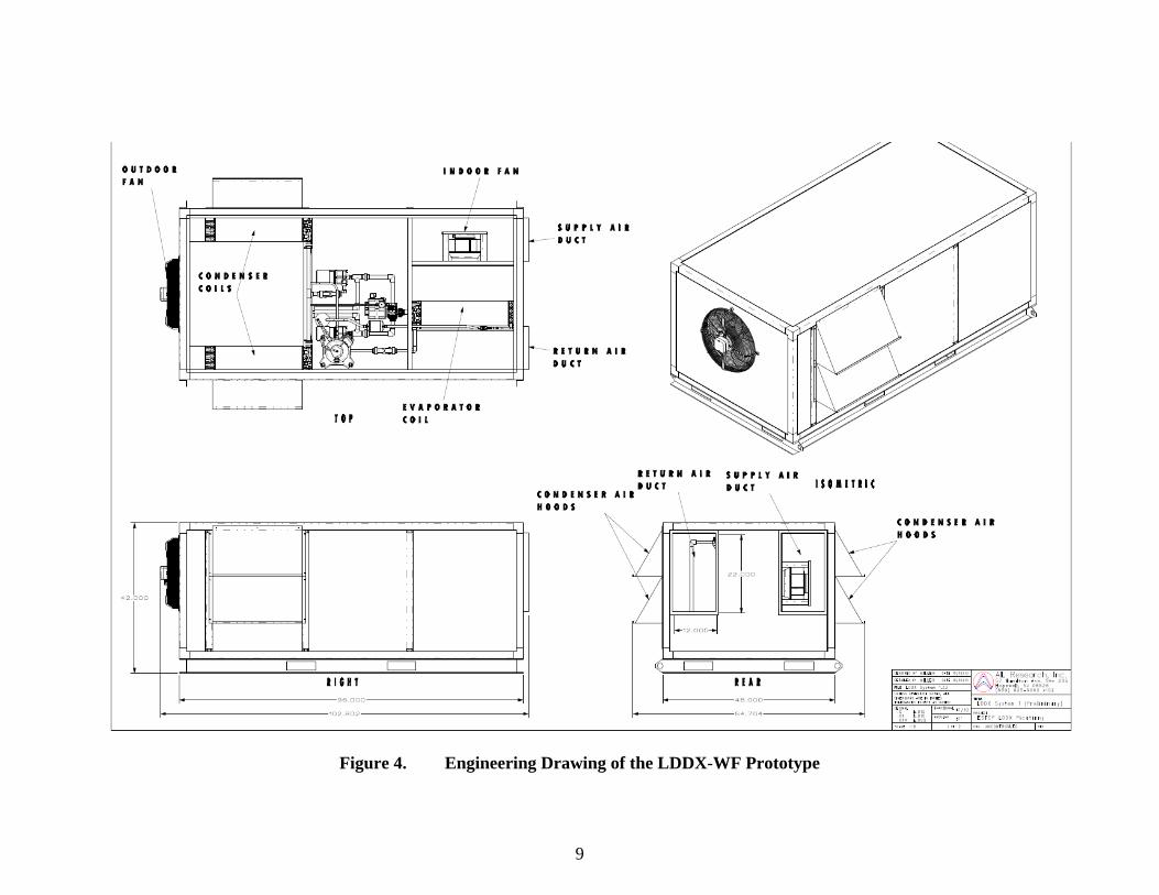
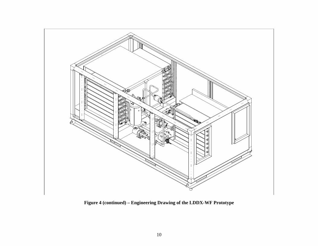
An engineering drawing of the LDDX-WF prototype is shown in Figure 4. This prototype is designed to be a high latent alternative to an air conditioner that processes the air recirculated in a building (i.e., a mix of return air and outdoor air, with the outdoor air typically being less than 20% of the total). At AHRI A-test conditions5, this prototype operating so that latent cooling is maximized is designed to supply 1,100 cfm of air at 72.3oF dry-bulb, 47.0oF dewpoint and 41% rh. Total cooling is 2.72 tons, 1.83 tons of which is latent cooling leading to an SHR6 of 0.32. The EER7 of this prototype is projected to be 10.5.
5 The AHRI A-Test condition specifies outdoor air at 95/75 F DB/WB and return air at 80/67 F DB/WB. The complete standard for Unitary Air Conditioning and Air-Source Het Pump Equipment (Standard 210/240) is available at: http://www.ahrinet.org/App_Content/ahri/files/standards%20pdfs/ANSI%20standards%20pdfs/ANSI.AHRI%20Standard%20210.240%20with%20Addenda%201%20and%202.pdf 6 An air conditioner’s Sensible Heat Ratio (SHR) is the fraction of total cooling that is supplied as sensible cooling (the balance being latent cooling). 7 An air conditioner’s Energy Efficiency Ratio (EER) is the total cooling it provides (Btu/h) divided by its total electrical power (W).
9
Figure 4. Engineering Drawing of the LDDX-WF Prototype
10
Figure 4 (continued) – Engineering Drawing of the LDDX-WF Prototype
11
2.1.3 Description – LDDX-Ad
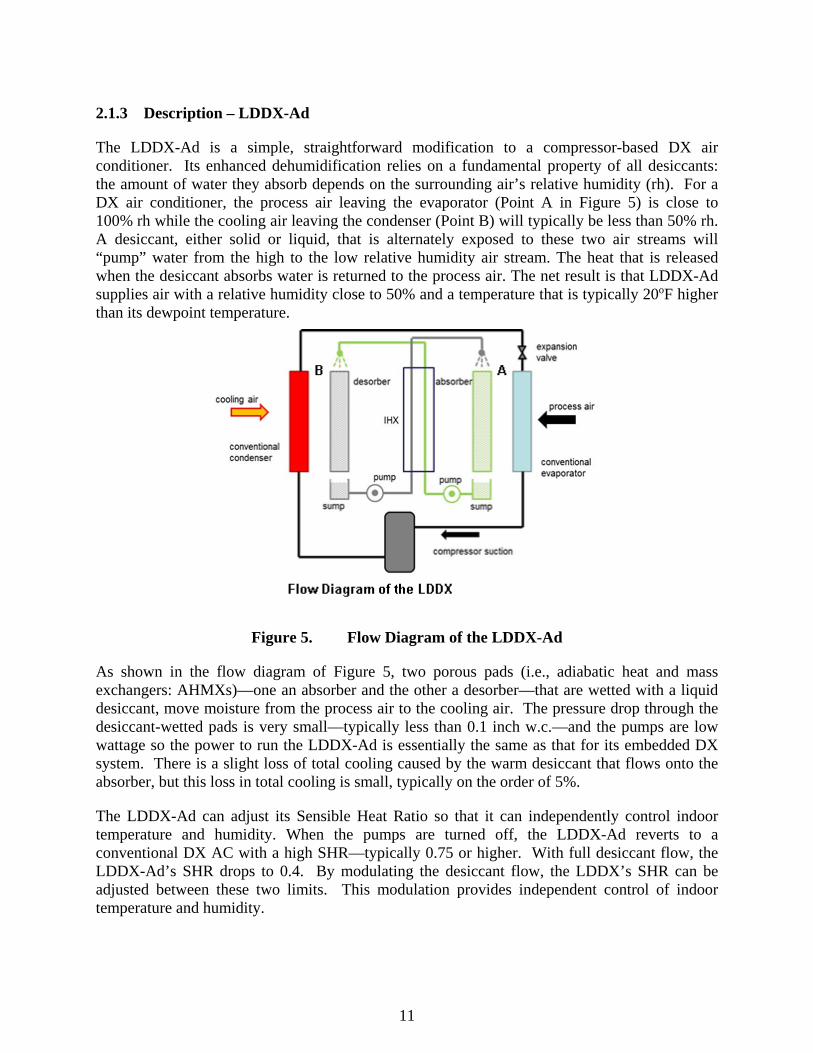
The LDDX-Ad is a simple, straightforward modification to a compressor-based DX air conditioner. Its enhanced dehumidification relies on a fundamental property of all desiccants: the amount of water they absorb depends on the surrounding air’s relative humidity (rh). For a DX air conditioner, the process air leaving the evaporator (Point A in Figure 5) is close to 100% rh while the cooling air leaving the condenser (Point B) will typically be less than 50% rh. A desiccant, either solid or liquid, that is alternately exposed to these two air streams will “pump” water from the high to the low relative humidity air stream. The heat that is released when the desiccant absorbs water is returned to the process air. The net result is that LDDX-Ad supplies air with a relative humidity close to 50% and a temperature that is typically 20oF higher than its dewpoint temperature.
Figure 5. Flow Diagram of the LDDX-Ad
As shown in the flow diagram of Figure 5, two porous pads (i.e., adiabatic heat and mass exchangers: AHMXs)—one an absorber and the other a desorber—that are wetted with a liquid desiccant, move moisture from the process air to the cooling air. The pressure drop through the desiccant-wetted pads is very small—typically less than 0.1 inch w.c.—and the pumps are low wattage so the power to run the LDDX-Ad is essentially the same as that for its embedded DX system. There is a slight loss of total cooling caused by the warm desiccant that flows onto the absorber, but this loss in total cooling is small, typically on the order of 5%.
The LDDX-Ad can adjust its Sensible Heat Ratio so that it can independently control indoor temperature and humidity. When the pumps are turned off, the LDDX-Ad reverts to a conventional DX AC with a high SHR—typically 0.75 or higher. With full desiccant flow, the LDDX-Ad’s SHR drops to 0.4. By modulating the desiccant flow, the LDDX’s SHR can be adjusted between these two limits. This modulation provides independent control of indoor temperature and humidity.
12
2.1.4 Visual Depiction—LDDX-Ad
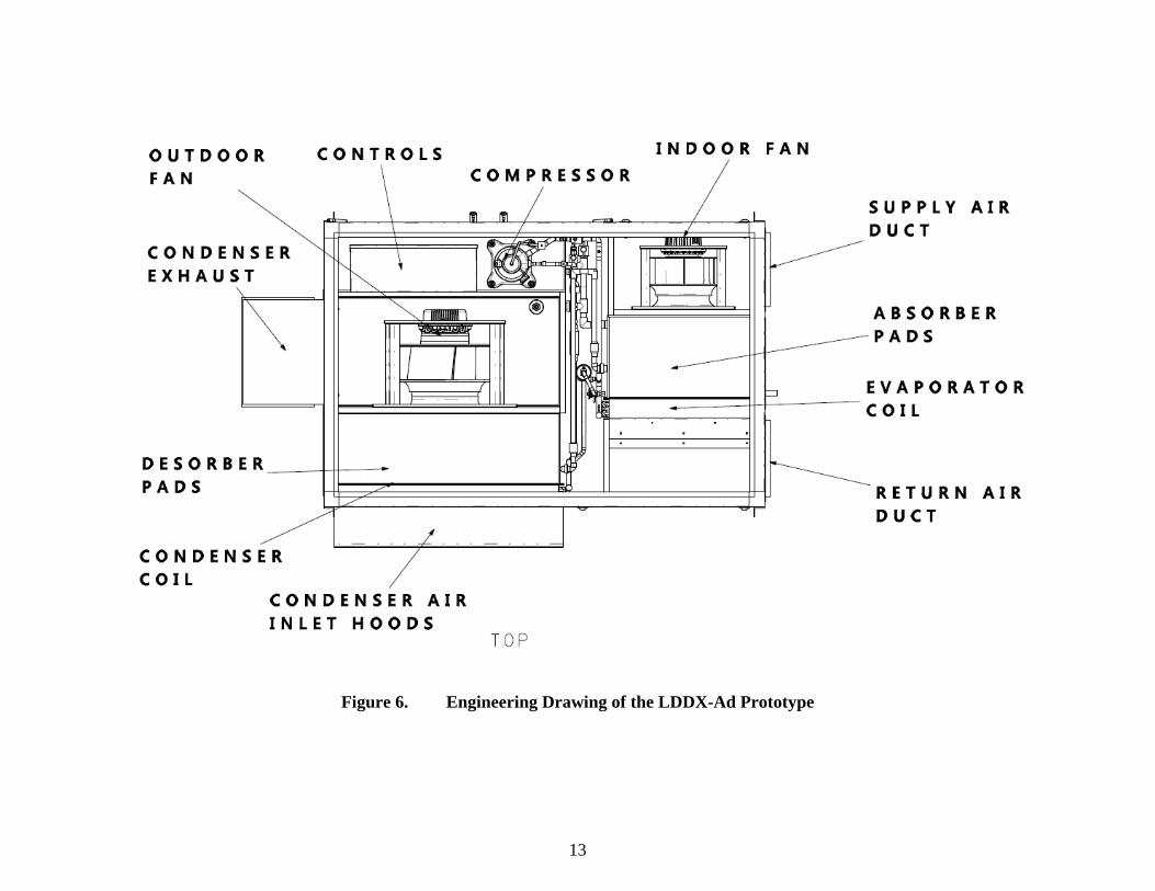
An engineering drawing of the LDDX-Ad prototype is shown in Figure 6. Similar to the LDDX-WF, the LDDX-Ad prototype is designed to be a high latent alternative to an air conditioner that processes the air recirculated in a building (i.e., a mix of return air and outdoor air, with the outdoor air typically being less than 20% of the total). At AHRI A-test conditions, this prototype is designed to supply 2,000 cfm of air at 69.5oF dry-bulb, 50.0oF dewpoint and 49.7% rh. Total cooling is 4.77 tons, 2.86 tons of which is latent cooling leading to an SHR of 0.40. The EER of this prototype is projected to be 11.4.
13
Figure 6. Engineering Drawing of the LDDX-Ad Prototype

14
Figure 6 (continued) – Engineering Drawing of the LDDX-Ad Prototype

15
2.1.5 Comparison to Existing Technology
The conventional, high latent alternative to the LDDX is a DX air conditioner that has a reheat coil immediately downstream of its evaporator. At least one HVAC manufacturer has implemented this reheat option as a dual refrigerant circuit with staged compressor operation. A first-stage compressor is part of a refrigerant circuit that can be switched between a configuration where all heat is rejected outdoors (i.e., operation without reheat) and a configuration where the hot refrigerant gas from the compressor partially condenses in a coil located downstream from the evaporator before fully condensing in an outdoor condenser (i.e., operation with reheat). The second-stage compressor is part of a conventional refrigerant circuit with an indoor evaporator and outdoor condenser. At AHRI A test conditions with both compressors operating a 7.5 ton model of this high-latent air conditioner operating without reheat would have a gross cooling capacity of 93,000 Btu/h, an SHR of 0.73, and an EER 12.7. Switching to reheat reduces sensible cooling by 25,000 Btu/h while leaving latent cooling almost unchanged. With gross cooling capacity reduced to 68,000 Btu/h but latent cooling unchanged at 25,200 Btu/h, the air conditioner's SHR drops to 0.63. Total compressor power is slightly less in reheat mode since the first stage condenser is now larger, but the loss of cooling capacity still drops the EER to 9.4.
It was previously reported that the LDDX-WF and LDDX-Ad operating at AHRI A conditions are projected to have SHRs of 0.32 and 0.40, respectively, and EERs of 10.5 and 11.4, respectively. If the conventional alternative to the LDDX is to further decrease its SHR from 0.63 to 0.408 it must operate part of the time with the second-stage compressor turned off leaving only the first-stage circuit operating in the reheat mode. When operating only with the first-stage circuit active, the conventional air conditioner’s SHR drops to 0.19 and its EER drops to 5.2. Assuming that averaged performance of the conventional air conditioner when it is cycling between two modes is a simple linear average of the two modes, the EER of the conventional air conditioner will drop to 7.2 when it matches the LDDX’s 0.40 SHR. Thus, the LDDX reduces electricity use by at least 37% in applications that require an SHR of 0.40 or lower.
When operating with the reheating coil active, the conventional condenser-reheat alternative to the LDDX is “undoing” a significant fraction of the gross cooling provided by its compressor. In the preceding example, the compressor capacity for a condenser-reheat air conditioner is 1.37 times larger than the net cooling provided by the air conditioner when its SHR has been reduced to 0.63. This required oversizing of the condenser-reheat air conditioner adversely affects manufacturing costs and unit size, further improving the LDDX’s competitiveness.
The LDDX’s efficient supply of latent cooling will incur additional benefits. By keeping indoor environments at a lower relative humidity, the LDDX will maintain comfort at higher thermostat settings. Higher indoor dry-bulb temperatures produce energy savings both by reducing building sensible loads and increasing the operating efficiency of the air conditioner.
8 The conventional DX AC with condenser reheat is compared to the LDDX-Ad since this version of the LDDX is most likely to be first launched as a commercial product
16
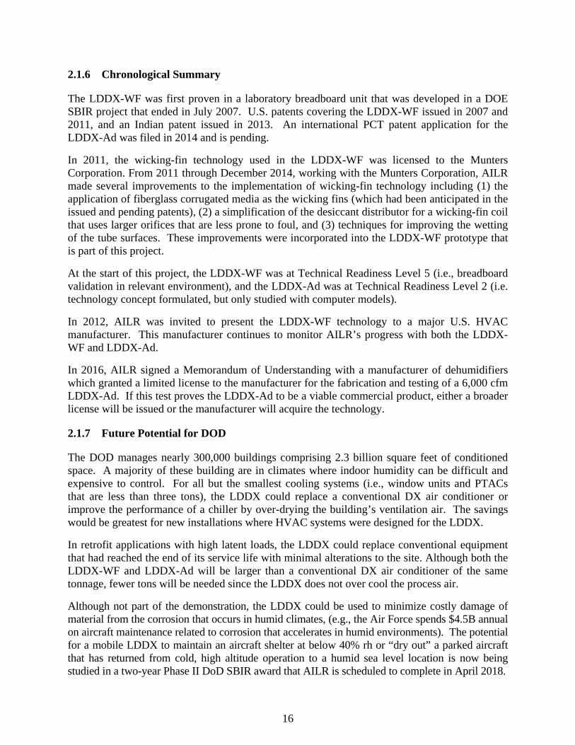
2.1.6 Chronological Summary
The LDDX-WF was first proven in a laboratory breadboard unit that was developed in a DOE SBIR project that ended in July 2007. U.S. patents covering the LDDX-WF issued in 2007 and 2011, and an Indian patent issued in 2013. An international PCT patent application for the LDDX-Ad was filed in 2014 and is pending.
In 2011, the wicking-fin technology used in the LDDX-WF was licensed to the Munters Corporation. From 2011 through December 2014, working with the Munters Corporation, AILR made several improvements to the implementation of wicking-fin technology including (1) the application of fiberglass corrugated media as the wicking fins (which had been anticipated in the issued and pending patents), (2) a simplification of the desiccant distributor for a wicking-fin coil that uses larger orifices that are less prone to foul, and (3) techniques for improving the wetting of the tube surfaces. These improvements were incorporated into the LDDX-WF prototype that is part of this project.
At the start of this project, the LDDX-WF was at Technical Readiness Level 5 (i.e., breadboard validation in relevant environment), and the LDDX-Ad was at Technical Readiness Level 2 (i.e. technology concept formulated, but only studied with computer models).
In 2012, AILR was invited to present the LDDX-WF technology to a major U.S. HVAC manufacturer. This manufacturer continues to monitor AILR’s progress with both the LDDX-WF and LDDX-Ad.
In 2016, AILR signed a Memorandum of Understanding with a manufacturer of dehumidifiers which granted a limited license to the manufacturer for the fabrication and testing of a 6,000 cfm LDDX-Ad. If this test proves the LDDX-Ad to be a viable commercial product, either a broader license will be issued or the manufacturer will acquire the technology.
2.1.7 Future Potential for DOD
The DOD manages nearly 300,000 buildings comprising 2.3 billion square feet of conditioned space. A majority of these building are in climates where indoor humidity can be difficult and expensive to control. For all but the smallest cooling systems (i.e., window units and PTACs that are less than three tons), the LDDX could replace a conventional DX air conditioner or improve the performance of a chiller by over-drying the building’s ventilation air. The savings would be greatest for new installations where HVAC systems were designed for the LDDX.
In retrofit applications with high latent loads, the LDDX could replace conventional equipment that had reached the end of its service life with minimal alterations to the site. Although both the LDDX-WF and LDDX-Ad will be larger than a conventional DX air conditioner of the same tonnage, fewer tons will be needed since the LDDX does not over cool the process air.
Although not part of the demonstration, the LDDX could be used to minimize costly damage of material from the corrosion that occurs in humid climates, (e.g., the Air Force spends $4.5B annual on aircraft maintenance related to corrosion that accelerates in humid environments). The potential for a mobile LDDX to maintain an aircraft shelter at below 40% rh or “dry out” a parked aircraft that has returned from cold, high altitude operation to a humid sea level location is now being studied in a two-year Phase II DoD SBIR award that AILR is scheduled to complete in April 2018.
17
2.2 TECHNOLOGY DEVELOPMENT
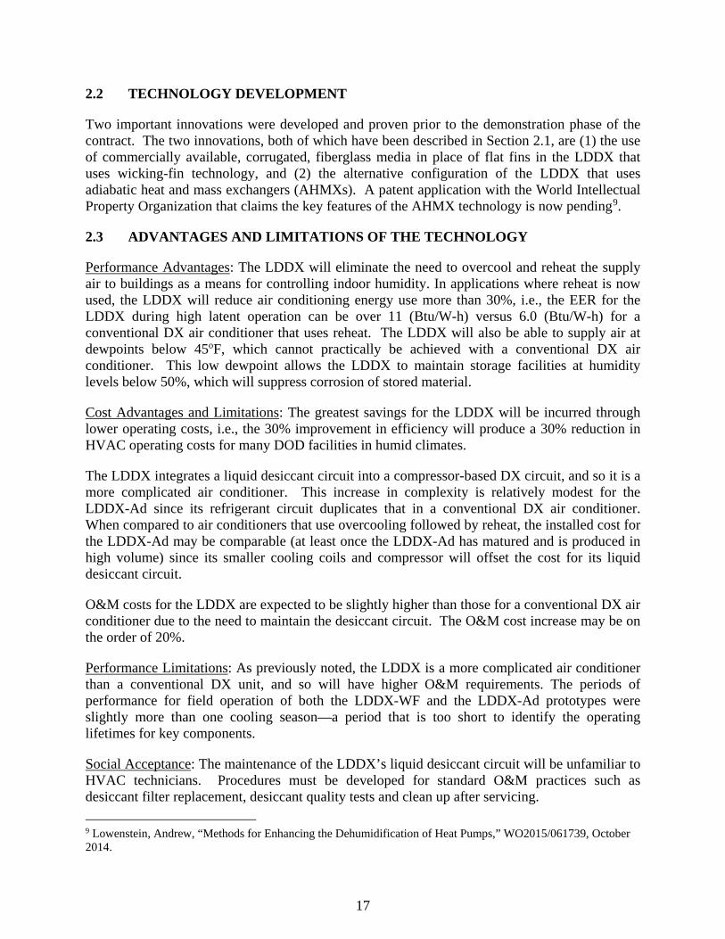
Two important innovations were developed and proven prior to the demonstration phase of the contract. The two innovations, both of which have been described in Section 2.1, are (1) the use of commercially available, corrugated, fiberglass media in place of flat fins in the LDDX that uses wicking-fin technology, and (2) the alternative configuration of the LDDX that uses adiabatic heat and mass exchangers (AHMXs). A patent application with the World Intellectual Property Organization that claims the key features of the AHMX technology is now pending9.
2.3 ADVANTAGES AND LIMITATIONS OF THE TECHNOLOGY
Performance Advantages: The LDDX will eliminate the need to overcool and reheat the supply air to buildings as a means for controlling indoor humidity. In applications where reheat is now used, the LDDX will reduce air conditioning energy use more than 30%, i.e., the EER for the LDDX during high latent operation can be over 11 (Btu/W-h) versus 6.0 (Btu/W-h) for a conventional DX air conditioner that uses reheat. The LDDX will also be able to supply air at dewpoints below 45oF, which cannot practically be achieved with a conventional DX air conditioner. This low dewpoint allows the LDDX to maintain storage facilities at humidity levels below 50%, which will suppress corrosion of stored material.
Cost Advantages and Limitations: The greatest savings for the LDDX will be incurred through lower operating costs, i.e., the 30% improvement in efficiency will produce a 30% reduction in HVAC operating costs for many DOD facilities in humid climates.
The LDDX integrates a liquid desiccant circuit into a compressor-based DX circuit, and so it is a more complicated air conditioner. This increase in complexity is relatively modest for the LDDX-Ad since its refrigerant circuit duplicates that in a conventional DX air conditioner. When compared to air conditioners that use overcooling followed by reheat, the installed cost for the LDDX-Ad may be comparable (at least once the LDDX-Ad has matured and is produced in high volume) since its smaller cooling coils and compressor will offset the cost for its liquid desiccant circuit.
O&M costs for the LDDX are expected to be slightly higher than those for a conventional DX air conditioner due to the need to maintain the desiccant circuit. The O&M cost increase may be on the order of 20%.
Performance Limitations: As previously noted, the LDDX is a more complicated air conditioner than a conventional DX unit, and so will have higher O&M requirements. The periods of performance for field operation of both the LDDX-WF and the LDDX-Ad prototypes were slightly more than one cooling season—a period that is too short to identify the operating lifetimes for key components.
Social Acceptance: The maintenance of the LDDX’s liquid desiccant circuit will be unfamiliar to HVAC technicians. Procedures must be developed for standard O&M practices such as desiccant filter replacement, desiccant quality tests and clean up after servicing. 9 Lowenstein, Andrew, “Methods for Enhancing the Dehumidification of Heat Pumps,” WO2015/061739, October 2014.

18
Page Intentionally Left Blank
19
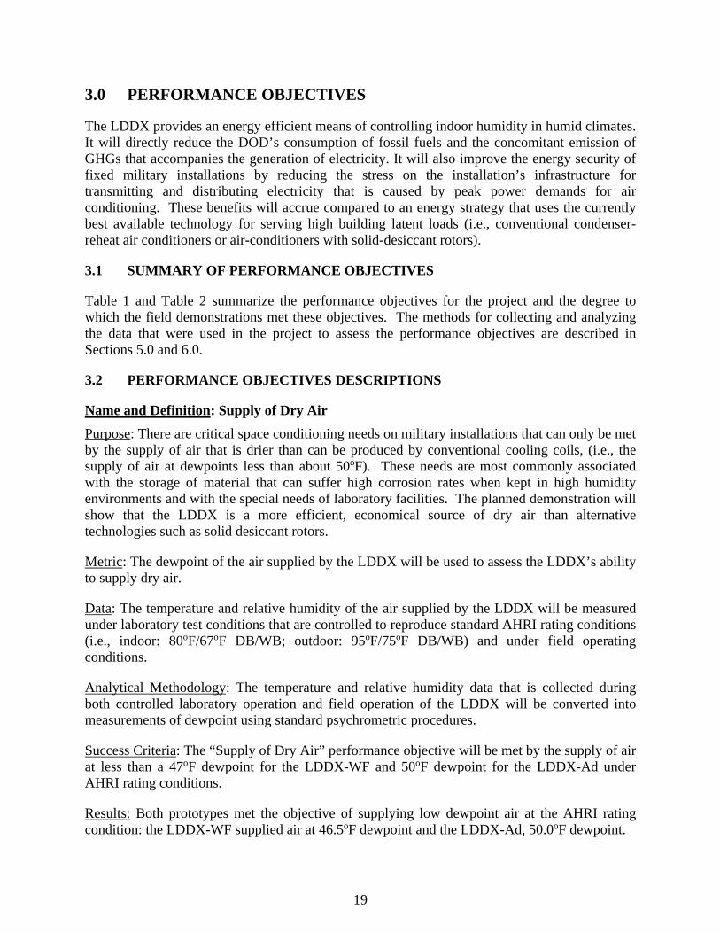
3.0 PERFORMANCE OBJECTIVES
The LDDX provides an energy efficient means of controlling indoor humidity in humid climates. It will directly reduce the DOD’s consumption of fossil fuels and the concomitant emission of GHGs that accompanies the generation of electricity. It will also improve the energy security of fixed military installations by reducing the stress on the installation’s infrastructure for transmitting and distributing electricity that is caused by peak power demands for air conditioning. These benefits will accrue compared to an energy strategy that uses the currently best available technology for serving high building latent loads (i.e., conventional condenser-reheat air conditioners or air-conditioners with solid-desiccant rotors).
3.1 SUMMARY OF PERFORMANCE OBJECTIVES
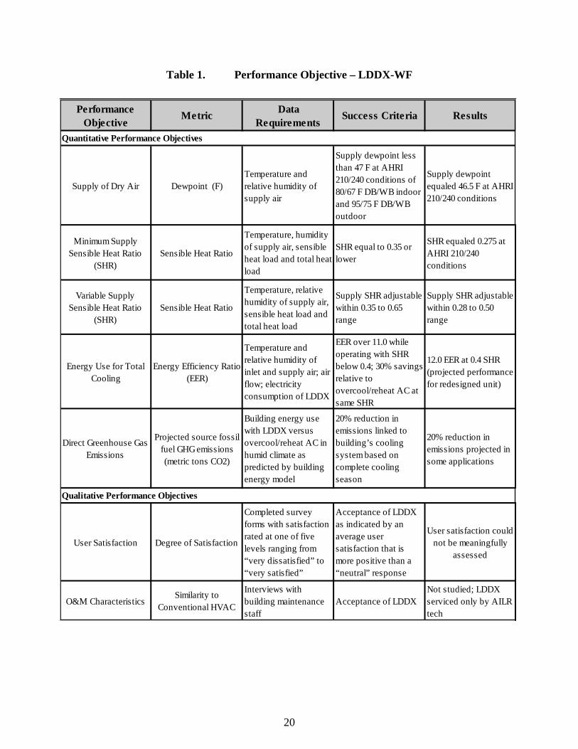
Table 1 and Table 2 summarize the performance objectives for the project and the degree to which the field demonstrations met these objectives. The methods for collecting and analyzing the data that were used in the project to assess the performance objectives are described in Sections 5.0 and 6.0.
3.2 PERFORMANCE OBJECTIVES DESCRIPTIONS
Name and Definition: Supply of Dry Air Purpose: There are critical space conditioning needs on military installations that can only be met by the supply of air that is drier than can be produced by conventional cooling coils, (i.e., the supply of air at dewpoints less than about 50oF). These needs are most commonly associated with the storage of material that can suffer high corrosion rates when kept in high humidity environments and with the special needs of laboratory facilities. The planned demonstration will show that the LDDX is a more efficient, economical source of dry air than alternative technologies such as solid desiccant rotors.
Metric: The dewpoint of the air supplied by the LDDX will be used to assess the LDDX’s ability to supply dry air.
Data: The temperature and relative humidity of the air supplied by the LDDX will be measured under laboratory test conditions that are controlled to reproduce standard AHRI rating conditions (i.e., indoor: 80oF/67oF DB/WB; outdoor: 95oF/75oF DB/WB) and under field operating conditions.
Analytical Methodology: The temperature and relative humidity data that is collected during both controlled laboratory operation and field operation of the LDDX will be converted into measurements of dewpoint using standard psychrometric procedures.
Success Criteria: The “Supply of Dry Air” performance objective will be met by the supply of air at less than a 47oF dewpoint for the LDDX-WF and 50oF dewpoint for the LDDX-Ad under AHRI rating conditions.
Results: Both prototypes met the objective of supplying low dewpoint air at the AHRI rating condition: the LDDX-WF supplied air at 46.5oF dewpoint and the LDDX-Ad, 50.0oF dewpoint.
20
Table 1. Performance Objective – LDDX-WF
Performance Objective
Metric Data Requirements
Success Criteria Results
Supply of Dry Air Dewpoint (F)Temperature and relative humidity of supply air
Supply dewpoint less than 47 F at AHRI 210/240 conditions of 80/67 F DB/WB indoor and 95/75 F DB/WB outdoor
Supply dewpoint equaled 46.5 F at AHRI 210/240 conditions
Minimum Supply Sensible Heat Ratio
(SHR)Sensible Heat Ratio
Temperature, humidity of supply air, sensible heat load and total heat load
SHR equal to 0.35 or lower
SHR equaled 0.275 at AHRI 210/240 conditions
Variable Supply Sensible Heat Ratio
(SHR)Sensible Heat Ratio
Temperature, relative humidity of supply air, sensible heat load and total heat load
Supply SHR adjustable within 0.35 to 0.65 range
Supply SHR adjustable within 0.28 to 0.50 range
Energy Use for Total Cooling
Energy Efficiency Ratio (EER)
Temperature and relative humidity of inlet and supply air; air flow; electricity consumption of LDDX
EER over 11.0 while operating with SHR below 0.4; 30% savings relative to overcool/reheat AC at same SHR
12.0 EER at 0.4 SHR (projected performance for redesigned unit)
Direct Greenhouse Gas Emissions
Projected source fossil fuel GHG emissions (metric tons CO2)
Building energy use with LDDX versus overcool/reheat AC in humid climate as predicted by building energy model
20% reduction in emissions linked to building’s cooling system based on complete cooling season
20% reduction in emissions projected in some applications
User Satisfaction Degree of Satisfaction
Completed survey forms with satisfaction rated at one of five levels ranging from “very dissatisfied” to “very satisfied”
Acceptance of LDDX as indicated by an average user satisfaction that is more positive than a “neutral” response
User satisfaction could not be meaningfully
assessed
O&M CharacteristicsSimilarity to
Conventional HVAC
Interviews with building maintenance staff
Acceptance of LDDXNot studied; LDDX serviced only by AILR tech
Quantitative Performance Objectives
Qualitative Performance Objectives

21
Table 2. Performance Objectives – LDDX-Ad
Performance Objective
Metric Data Requirements
Success Criteria Results
Supply of Dry Air Dewpoint (F)Temperature and relative humidity of supply air
Supply dewpoint less than 50 F at AHRI 210/240 conditions of 80/67 F DB/WB indoor and 95/75 F DB/WB outdoor
Supply dewpoint equaled 50 F at AHRI 210/240 conditions
Minimum Supply Sensible Heat Ratio
(SHR)Sensible Heat Ratio
Temperature, humidity of supply air, sensible heat load and total heat load
SHR equal to 0.40 or lower
SHR equaled 0.403 at AHRI 210/240 conditions
Variable Supply Sensible Heat Ratio
(SHR)Sensible Heat Ratio
Temperature, relative humidity of supply air, sensible heat load and total heat load
Supply SHR adjustable within 0.40 to 0.70 range
Supply SHR ranged from 0.403 (desiccant on) to 0.78 (desiccant off)
Energy Use for Total Cooling
Energy Efficiency Ratio (EER)
Temperature and relative humidity of inlet and supply air; air flow; electricity consumption of LDDX
EER over 11.0 while operating with SHR below 0.4; 30% savings relative to overcool/reheat AC at same SHR
EER equaled 11.46 while operating at 0.403 SHR
Direct Greenhouse Gas Emissions
Projected source fossil fuel GHG emissions (metric tons CO2)
Building energy use with LDDX versus overcool/reheat AC in humid climate as predicted by building energy model
20% reduction in emissions linked to building’s cooling system based on complete cooling season
20% reduction in emissions projected in some applications
User Satisfaction Degree of Satisfaction
Completed survey forms with satisfaction rated at one of five levels ranging from “very dissatisfied” to “very satisfied”
Acceptance of LDDX as indicated by an average user satisfaction that is more positive than a “neutral” response
Very favorable comments from Ft Belvoir energy manager and zone occupants
O&M CharacteristicsSimilarity to
Conventional HVAC
Interviews with building maintenance staff
Acceptance of LDDXNot studied; LDDX serviced only by AILR tech
Quantitative Performance Objectives
Qualitative Performance Objectives
22
Name and Definition: Minimum Supply Sensible Heat Ratio (SHR)
Purpose: A building’s cooling system will maintain indoor comfort only when it serves both the latent loads and the sensible loads on the building. While a conventional cooling coil can condense water from the process air, it typically provides much more sensible cooling than latent cooling (i.e., it will have a Sensible Heat Ratio that is greater than 0.7). Many applications require cooling systems with lower SHRs since their latent loads are large. The planned demonstration will show that the LDDX can provide most of its cooling as latent cooling without the use of reheat during field operation.
Metric: The Sensible Heat Ratio (SHR) of the cooling supplied by the LDDX will be used to assess the LDDX’s ability to maintain indoor comfort when latent loads are large compared to sensible loads.
Data: The temperature and relative humidity of both the inlet air to and the outlet air from the LDDX will be measured during field operation.
Analytical Methodology: The temperature and relative humidity data that is collected during field operation of the LDDX will be converted into measurements of the enthalpy and the absolute humidity of the inlet and outlet air. These calculated air properties will then be used to determine the total cooling, latent cooling, sensible cooling (i.e., the difference between total cooling and latent cooling) and the SHR for the LDDX.
Success Criteria: The “Minimum Supply SHR” performance objective will be met by a demonstrated SHR of less than 0.35 for the LDDX-WF and 0.40 for the LDDX-Ad operating at conditions that approach the AHRI rating conditions.
Results: The LDDX-WF exceeded it performance objective by operating with a 0.275 SHR at the AHRI rating condition. The LDDX-Ad essentially met its performance objective by operating with a 0.403 SHR.
Name and Definition: Variable Supply Sensible Heat Ratio (SHR)
Purpose: In most applications, the sensible and latent loads on a building will vary throughout the cooling season. Often, the variations can be large (i.e., on hot, dry days cooling loads may be mostly sensible but on mild, rainy days they may be mostly latent). A cooling system that can independently vary its SHR will provide superior indoor comfort. Furthermore, if the SHR can be varied without resorting to reheat, energy use for space conditioning can be kept to a minimum. The planned demonstration will show that the LDDX can vary its SHR and, therefore, independently control indoor temperature and humidity without the use of reheat.
Metric: The Sensible Heat Ratio (SHR) of the cooling supplied by the LDDX will be used to assess the LDDX’s ability to maintain indoor comfort when latent and sensible loads vary.
Data: The temperature and relative humidity of both the inlet air to and the outlet air from the LDDX will be measured under field operation.
23
Analytical Methodology: For the LDDX-WF, the SHR will be varied by changing the amount of desiccant recirculated to its evaporator. For the LDDX-Ad, the SHR will be varied by pulsing the flow of liquid desiccant to both the absorber and desorber. The temperature and relative humidity data that is collected during each operating state of the LDDX will be converted into measurements of the enthalpy and the absolute humidity of the inlet and outlet air. These calculated air properties will then be used to determine the total cooling, latent cooling, sensible cooling (i.e., the difference between total cooling and latent cooling) and the SHR for each operating state of the LDDX.
Success Criteria: The “Variable Supply SHR” performance objective will be met by a demonstrated control of the LDDX-WF’s SHR between 0.35 and 0.65 and the LDDX-Ad’s SHR between 0.40 and 0.70.
Results: Although it did not meet the objective of modulating its SHR between 0.35 and 0.65, the LDDX-WF prototype did modulate its SHR over a wide range that should prove useful in controlling indoor humidity, i.e., it modulated its SHR between 0.28 and 0.50. The LDDX-Ad, which operates as a conventional DX air conditioner when its desiccant flows are turned off, did meet the “Variable Supply SHR” objective: it modulated its SHR between 0.403 and 0.78.
Name and Definition: Energy Use for Total Cooling
Purpose: A primary goal of this demonstration is to show that comfortable indoor conditions can be maintained in a large segment of DOD’s fixed installations with a significant reduction in energy use compared to current methods that rely on over-cooling/reheat to control indoor humidity.
Metric: The Energy Efficiency Ratio (EER), which is defined as the Btu per hour of cooling provided by a cooling system divided by its power use measured in Watts, will be used to measure LDDX’s efficiency.
Data: A cooling system’s EER can be calculated from measurements of the total cooling the unit supplies and its electricity consumption. In addition to the temperature and relative humidity of both the inlet air to and the outlet air from the LDDX (which are required to calculate SHR), the calculation of total cooling requires a measurement of the volumetric flow of air processed by the LDDX. The data required to calculate the LDDX’s EER, including its power consumption, will be measured during field operation.
Analytical Methodology: The temperature and relative humidity data that is collected during the controlled laboratory operation of the LDDX will be converted into calculated values of the enthalpy of the inlet and outlet air. The measured volumetric air flow will be converted into calculated air mass flow rate. The total cooling provided by the LDDX is then the product of the air mass flow rate and the change in air enthalpy across the LDDX. The electrical power drawn by the LDDX will be directly measured and the EER calculated as the ratio of the total cooling divided by the electrical power.
Success Criteria: The “Energy Use for Total Cooling” performance objective will be met by a demonstrated EER over 11.0 during field operation that approximates AHRI rating conditions with a SHR less than 0.4.
24
Results: The as-built LDDX-WF prototype did not meet the 11.0 EER performance objective: at the AHRI rating conditions, its EER was 9.3. However, computer modeling of the performance of an LDDX-WF modified to have a 1.5X larger evaporator and condenser predicted an AHRI EER of 12.0. The LDDX-Ad prototype exceeded its energy-use performance objective by operating at an 11.46 EER.
Name and Definition: Direct Greenhouse Gas Emissions
Purpose: Fossil fuels dominant the mix for power generation in the U.S. The reduction in energy use for total cooling incurred by the LDDX will produce a concomitant reduction in greenhouse gas emissions.
Metric: The impact of the LDDX on greenhouse gas emissions will be measured in terms of annual tons of carbon dioxide released to the atmosphere from the generation of electricity.
Data: The electrical energy use for the LDDX will be measured under field test conditions.
Analytical Methodology: The measured electrical energy use for the LDDX will be used to project annual electricity consumption of the LDDX versus a conventional cooling system that serves the same load. This comparison will be performed using a computer model that simulates the operation of a cooling system on a simplified representation of a building in several climate zones.
Success Criteria: The “Greenhouse Gas Emissions” performance objective will be met by modeling projections that show the potential for the LDDX to reduce emissions by 20%.
Results: By meeting their performance objective for efficiency, both the LDDX-WF with a larger evaporator and condenser, and the as-built LDDX-Ad prototype are expected to reduce greenhouse gas emissions by at least 20% when applied in applications with high latent loads.
Name and Definition: User Satisfaction
Purpose: Many parameters enter into a purchasing decision for a new cooling system. While some parameters such as EER and SHR can be directly measured, others such as O&M characteristics and the unit’s ability to follow changing loads are more difficult to quantify. A measurement of the user’s overall satisfaction with LDDX provides qualitative information on the user’s acceptance of the new technology.
Metric: A measure of Degree of Satisfaction of the personnel responsible for operating and maintaining the HVAC systems at the Picatinny Arsenal and Fort Belvoir will be the key metric for this performance objective.
Data: Depending on the number of people with relevant experience operating and maintaining the LDDX, user satisfaction data will be collected either with survey forms or through interviews. Respondents will be asked to rate on a scale of one to five (“one” corresponding to “very dissatisfied” and “five”, “very satisfied”) their impressions/experience with the following characteristics of the LDDX: (a) installation, (b) start-up, (c) ability of unit to maintain indoor comfort, (d) possible impact of unit on humidity related problems within the building, (e) routine maintenance of the unit, (f) reliability, (g) overall satisfaction with the unit, and

25
(h) likelihood of applying similar units to other installations. User satisfaction with the LDDX’s performance will be assessed against respondents’ impressions/experience during test periods when the conventional cooling system was operating.
Analytical Methodology: Not applicable.
Success Criteria: The “User Satisfaction” performance objective will be met by a subjective evaluation of the survey/interview data that leads to the conclusion that the user is likely to apply the LDDX in at other installations.
Results: Due to limitations imposed by the test site at Picatinny Arsenal, the LDDX-WF prototype did not significantly lower indoor relative humidity in the test zone. With indoor conditions essentially unchanged, it was not possible to get a meaningful assessment of user satisfaction. At Fort Belvoir, both the on-site coordinator for the field test and the occupants that worked within the test zone reported much improved comfort levels with no unfavorable changes to the indoor environment.
Name and Definition: O&M Characteristics
Purpose: Understand the training of maintenance staff that will be required to support the installation of the LDDX on multiple buildings at DOD installations.
Metric: Description of the similarities and differences between the maintenance needs of the LDDX and conventional cooling systems.
Data: The impressions/opinions/evaluations of personnel directly involved in operating and maintaining the LDDX regarding the acceptability of the unit.
Analytical Methodology: Not applicable.
Success Criteria: The LDDX will be judged an acceptable HVAC system if the interviews of maintenance staff do not identify routine procedures that would be difficult to implement through reasonable training.
Results: At both test sites, the maintenance of the prototypes was the responsibility of an AILR technician throughout the tests. Consequently, the bases’ maintenance staffs could not comment on the serviceability of the prototypes.

26
Page Intentionally Left Blank
27
4.0 FACILITY/SITE DESCRIPTION
4.1 PICATINNY ARSENAL: FACILITY/SITE LOCATION AND OPERATIONS
As described on the website for Picatinny Arsenal,
Picatinny Arsenal is the Joint Center of Excellence for Armaments and Munitions, providing products and services to all branches of the U.S. military… Located about 35 miles west of New York City, Picatinny has more than 1,010 permanent structures, including 64 laboratories, situated on the installation's nearly 6,500 acres. As one of the largest employers in Morris County, we employ about 3,907 civilians, approximately 93 military personnel and about 1,035 contractors. Approximately half of these employees are engineers and scientists.
Building 407 at the Picatinny Arsenal met all preceding site-selection criteria. The central New Jersey location of the arsenal has hot and humid summers and it is about a one-hour drive from AILR’s Hopewell office.
Building 407 had several packaged air conditioners mounted outdoors on concrete slabs next to the building. These packaged air conditioners had adequate surrounding space for installing the LDDXs. Furthermore, the LDDXs were easily transported to their proposed locations next to the building.
Work within Building 407 in no way limited access to the building. Furthermore, there was no chemistry or biology laboratory work that required exceptionally tight control of the indoor environment with no disruptions (as might occur during the test of a new cooling technology).
Demonstration Site Description: Building 407 is located at the intersection of 9th Street and Buffington Road at Picatinny Arsenal, Rockaway Township, NJ. The building is a single-story, 21,000 square foot structure that was built in 1942. The building is approximately evenly split between administrative offices and electronics labs.
Key Operations: As described in its website, Picatinny Arsenal “specializes in the research, development, acquisition and lifecycle management of advanced conventional weapon systems and advanced ammunition” No interaction occurred between the key R&D and testing activities at the arsenal and the LDDX field test.
Command Support: Both the on-site Resource Efficiency Manager (Mr. Nicholas Stecky) and the head of Chevron Energy Services (Mr. Stephen Brod, the site’s performance contractor) were interested in the possible benefits offered by the LDDX. Both gentlemen were active in the early planning of the field test and closely monitored the progress of the field demonstration.
Communications: The communication network at Picatinny Arsenal was not used for data collection. Instead, a cellular modem was used to daily download test data from the site. Mr. Nicholas Stecky, the on-site Resource Efficiency Manager, worked with the IT/security staff at Picatinny Arsenal to obtain approval for the use of the cellular modem. Information created during the field test will be disseminated through workshops, webcasts and DOD events, such as the annual Defense Energy Summit.

28
Location/Site Map: The blue pin on the following map marks the location of the test building within the Picatinny Arsenal.
Figure 7. Map of the Test Site within the Picatinny Arsenal
4.2 FORT BELVOIR: FACILITY/SITE LOCATION AND OPERATIONS
As described on the website for Fort Belvoir,
Fort Belvoir is home to the United States INSCOM and ARCYBER and elements of ten other Army major commands; nineteen different agencies and direct reporting units of the Department of Army; eight elements of the U.S. Army Reserve and the Army National Guard; and twenty-six Department of Defense agencies. Also located here are the 249th Engineer Battalion (Prime Power), the U.S. Army Prime Power School, a Marine Corps detachment, a U.S. Air Force activity, U.S. Army Audit Agency, and an agency from the Department of the Treasury.
Building 392 at Fort Belvoir met all preceding site-selection criteria. The northern Virginia location of the base has hot and humid summers and it is about a four-hour drive from AILR’s Hopewell office.
An approximately 2,000 square feet zone on the west side of the second floor of Building 392 served by a 4.5 ton packaged air conditioner. This air conditioner had no provisions for ventilation air. It also poorly controlled humidity within the zone as evidenced by locations where condensation dripped off above-ceiling, uninsulated supply ducts, leading to stained ceiling tiles and in at least one location wet areas of carpet.
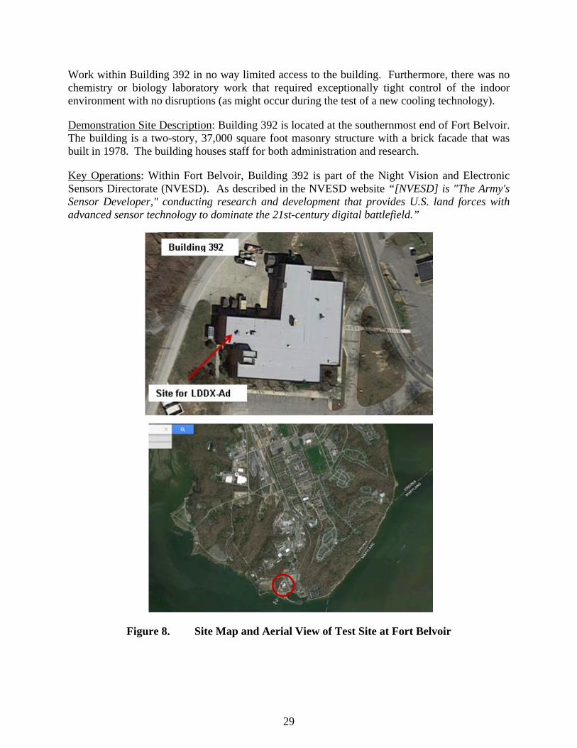
29
Work within Building 392 in no way limited access to the building. Furthermore, there was no chemistry or biology laboratory work that required exceptionally tight control of the indoor environment with no disruptions (as might occur during the test of a new cooling technology).
Demonstration Site Description: Building 392 is located at the southernmost end of Fort Belvoir. The building is a two-story, 37,000 square foot masonry structure with a brick facade that was built in 1978. The building houses staff for both administration and research.
Key Operations: Within Fort Belvoir, Building 392 is part of the Night Vision and Electronic Sensors Directorate (NVESD). As described in the NVESD website “[NVESD] is "The Army's Sensor Developer," conducting research and development that provides U.S. land forces with advanced sensor technology to dominate the 21st-century digital battlefield.”
Figure 8. Site Map and Aerial View of Test Site at Fort Belvoir
30
Command Support: Mr. William Elliott, Master Planner, Facilities & Energy, was interested in the LDDX as a possible low-energy means of solving indoor humidity problems in NVESD buildings. Mr. Elliott was active in the early planning of the field test and closely monitored the progress of the field demonstration. Communications: The communication network at Fort Belvoir was not used for data collection. Instead, a cellular modem downloaded test data from the site. To insure that the cellular modem had a strong signal for sending data and that it did not interfere with any wireless communication systems at Fort Belvoir, AILR provided a detailed description of the LDDX’s communication subsystem (i.e., the data logger, the cellular modem and the serial device server) to Mr. William Horner (Communications - Electronics Research, Development and Engineering Center) at Fort Belvoir who approved the installation. Information created during the field test will be disseminated through workshops, webcasts and DOD events, such as the annual Defense Energy Summit. Location/Site Map: The red circle on the following map marks the location of the test building within the Fort Belvoir.

31
5.0 TEST DESIGN
The LDDX prototypes were tested both in a controlled laboratory setting and on a building under conditions representative of a commercial cooling system. The laboratory tests were conducted at AIL Research, Hopewell, NJ. The field tests were conducted on Building 407 at the Picatinny Arsenal and Building 392 at Fort Belvoir.
Fundamental Problem: The laboratory tests documented the performance of the two LDDXs under conditions that are the AHRI standards for rating air conditioners. The field test demon-strated that the LDDX is a preferred alternative to a conventional compressor-based air conditioner in humid climates.
Demonstration Question: In both the laboratory tests and field tests, performance data was collected that measured the latent cooling capacity, the total cooling capacity and the Energy Efficiency Ratio (EER) of the LDDX. The field test also determined whether the O&M procedures required to ensure reliable operation of the LDDX are compatible with the functions commonly performed by a base’s maintenance staff.
5.1 CONCEPTUAL TEST DESIGN
The laboratory tests of the two LDDXs had the following measureable characteristics:
5.1.1 Independent variables
process air inlet temperature process air inlet humidity process air volumetric flow rate condenser air inlet temperature condenser air inlet humidity condenser air volumetric flow rate evaporator/absorber desiccant flow rate condenser/desorber desiccant flow rate evaporator desiccant recirculation rate (LDDX-WF) compressor unloading (LDDX-WF)
5.1.2 Dependent variable
process air outlet temperature process air outlet humidity process air fan power condenser air outlet temperature condenser air outlet humidity condenser air fan power
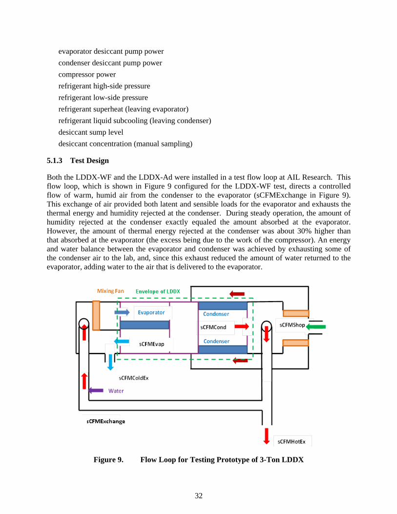
32
evaporator desiccant pump power condenser desiccant pump power compressor power refrigerant high-side pressure refrigerant low-side pressure refrigerant superheat (leaving evaporator) refrigerant liquid subcooling (leaving condenser) desiccant sump level desiccant concentration (manual sampling)
5.1.3 Test Design
Both the LDDX-WF and the LDDX-Ad were installed in a test flow loop at AIL Research. This flow loop, which is shown in Figure 9 configured for the LDDX-WF test, directs a controlled flow of warm, humid air from the condenser to the evaporator (sCFMExchange in Figure 9). This exchange of air provided both latent and sensible loads for the evaporator and exhausts the thermal energy and humidity rejected at the condenser. During steady operation, the amount of humidity rejected at the condenser exactly equaled the amount absorbed at the evaporator. However, the amount of thermal energy rejected at the condenser was about 30% higher than that absorbed at the evaporator (the excess being due to the work of the compressor). An energy and water balance between the evaporator and condenser was achieved by exhausting some of the condenser air to the lab, and, since this exhaust reduced the amount of water returned to the evaporator, adding water to the air that is delivered to the evaporator.
Figure 9. Flow Loop for Testing Prototype of 3-Ton LDDX
33
5.1.4 Test Phases
The initial operation of both LDDXs focused on developing a start-up sequence of pumps, fans and compressor that ensured good wetting by the desiccant of both the absorbing and desorbing components prior to the operation of the fans and compressor. The start-up sequence was implemented in the LDDX’s PLC control unit. Once the prototypes operated under PLC control the test series at different simulated indoor/outdoor conditions previously described was executed. The field tests of the LDDXs, which followed the laboratory tests, had the following characteristics:
5.1.5 Pre-set variables
desiccant flow rate compressor unloading (none) process air volumetric flow rate condenser air volumetric flow rate ventilation air volumetric flow rate indoor thermostat setpoint indoor humidistat setpoint (optional)
5.1.6 Uncontrolled variables
outdoor air temperature outdoor air humidity process air inlet temperature process air inlet humidity
5.1.7 Dependent variable
process air outlet temperature process air outlet humidity process air fan power condenser air outlet temperature condenser air outlet humidity condenser air fan power evaporator/absorber desiccant pump power condenser/desorber desiccant pump power compressor power indoor zone temperature indoor zone humidity refrigerant high-side pressure
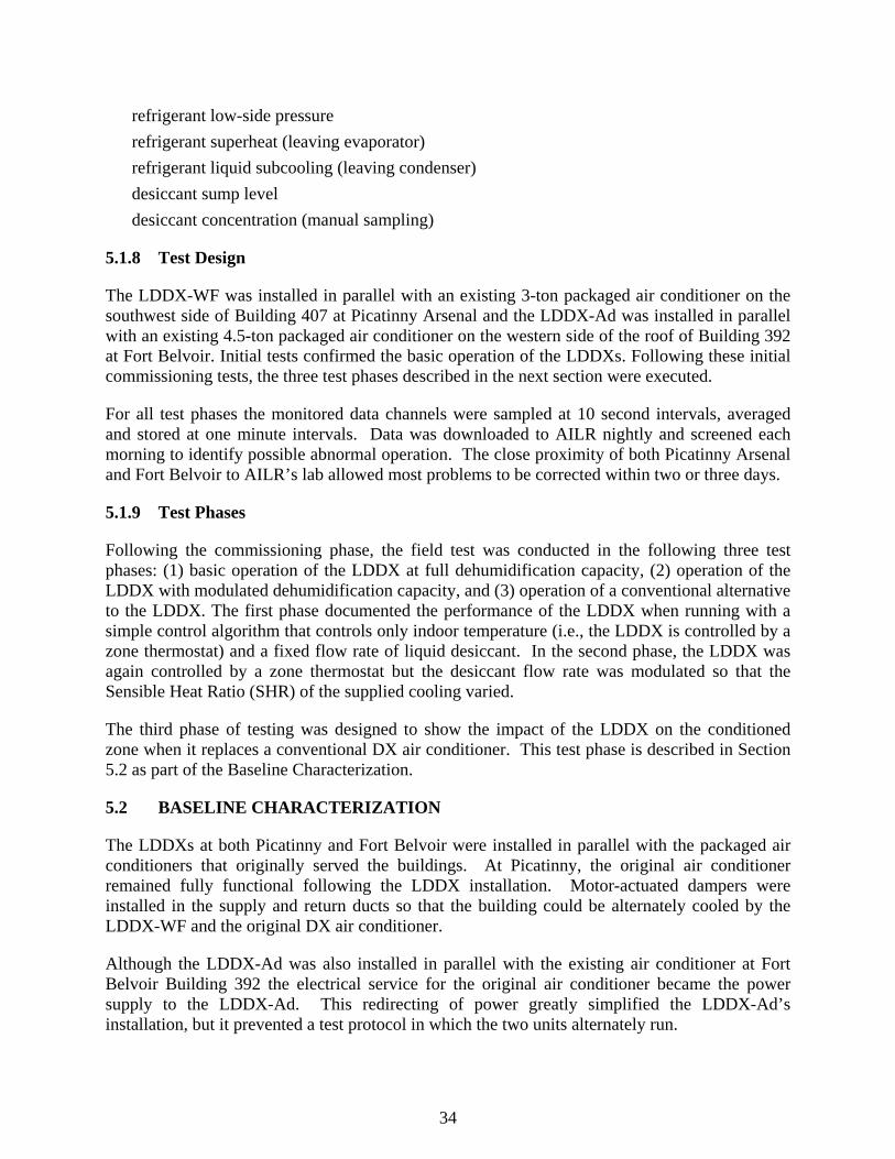
34
refrigerant low-side pressure refrigerant superheat (leaving evaporator) refrigerant liquid subcooling (leaving condenser) desiccant sump level desiccant concentration (manual sampling)
5.1.8 Test Design
The LDDX-WF was installed in parallel with an existing 3-ton packaged air conditioner on the southwest side of Building 407 at Picatinny Arsenal and the LDDX-Ad was installed in parallel with an existing 4.5-ton packaged air conditioner on the western side of the roof of Building 392 at Fort Belvoir. Initial tests confirmed the basic operation of the LDDXs. Following these initial commissioning tests, the three test phases described in the next section were executed.
For all test phases the monitored data channels were sampled at 10 second intervals, averaged and stored at one minute intervals. Data was downloaded to AILR nightly and screened each morning to identify possible abnormal operation. The close proximity of both Picatinny Arsenal and Fort Belvoir to AILR’s lab allowed most problems to be corrected within two or three days.
5.1.9 Test Phases
Following the commissioning phase, the field test was conducted in the following three test phases: (1) basic operation of the LDDX at full dehumidification capacity, (2) operation of the LDDX with modulated dehumidification capacity, and (3) operation of a conventional alternative to the LDDX. The first phase documented the performance of the LDDX when running with a simple control algorithm that controls only indoor temperature (i.e., the LDDX is controlled by a zone thermostat) and a fixed flow rate of liquid desiccant. In the second phase, the LDDX was again controlled by a zone thermostat but the desiccant flow rate was modulated so that the Sensible Heat Ratio (SHR) of the supplied cooling varied.
The third phase of testing was designed to show the impact of the LDDX on the conditioned zone when it replaces a conventional DX air conditioner. This test phase is described in Section 5.2 as part of the Baseline Characterization.
5.2 BASELINE CHARACTERIZATION
The LDDXs at both Picatinny and Fort Belvoir were installed in parallel with the packaged air conditioners that originally served the buildings. At Picatinny, the original air conditioner remained fully functional following the LDDX installation. Motor-actuated dampers were installed in the supply and return ducts so that the building could be alternately cooled by the LDDX-WF and the original DX air conditioner.
Although the LDDX-Ad was also installed in parallel with the existing air conditioner at Fort Belvoir Building 392 the electrical service for the original air conditioner became the power supply to the LDDX-Ad. This redirecting of power greatly simplified the LDDX-Ad’s installation, but it prevented a test protocol in which the two units alternately run.

35
The baseline characterization of the Building 407 HVAC system at Picatinny was its performance during the weeks when the LDDX-WF was replaced by the existing conventional air conditioner. Unfortunately, as is discussed in a later section, the baseline characterization of the conventional DX air conditioner was compromised by a strong coupling between neighboring zones within the building. This coupling allowed the DX air conditioners for neighboring zones to serve some of the loads within the test zone.
The baseline characterization of the Building 392 HVAC system at Fort Belvoir included the measurement and recording of the indoor temperature and relative humidity in two offices at ten-minute intervals over a 12 day period prior to the installation of the LDDX-Ad. The zone within Building 392 that was served by the LDDX-Ad had humidity problems that produced leaks of condensate through the zone’s hung ceiling. The baseline characterization included photographs of the damage caused by this condensation.
The baseline characterization of Building 392 at Fort Belvoir also included the operation of the LDDX-Ad in a mode in which the liquid desiccant circuit was turned off converting the prototype into a conventional DX air conditioner.
5.3 DESIGN AND LAYOUT OF SYSTEM COMPONENTS
The installation sites for the LDDX-Ad at Fort Belvoir and the LDDX-WF at Picatinny are shown in the right and left photographs, respectively, of Figure 10. The layout of the LDDX-WF installation at Picatinny Arsenal including instrumentation that was not internal to the unit is shown in Figure 11. As shown in this figure the LDDX-WF was installed in parallel with the existing air conditioner. Dampers in the ducts could be adjusted to direct the recirculated air through the LDDX or through the conventional air conditioner.
Figure 10. Installation Sites: Fort Belvoir (left) and Picatinny Arsenal (right)
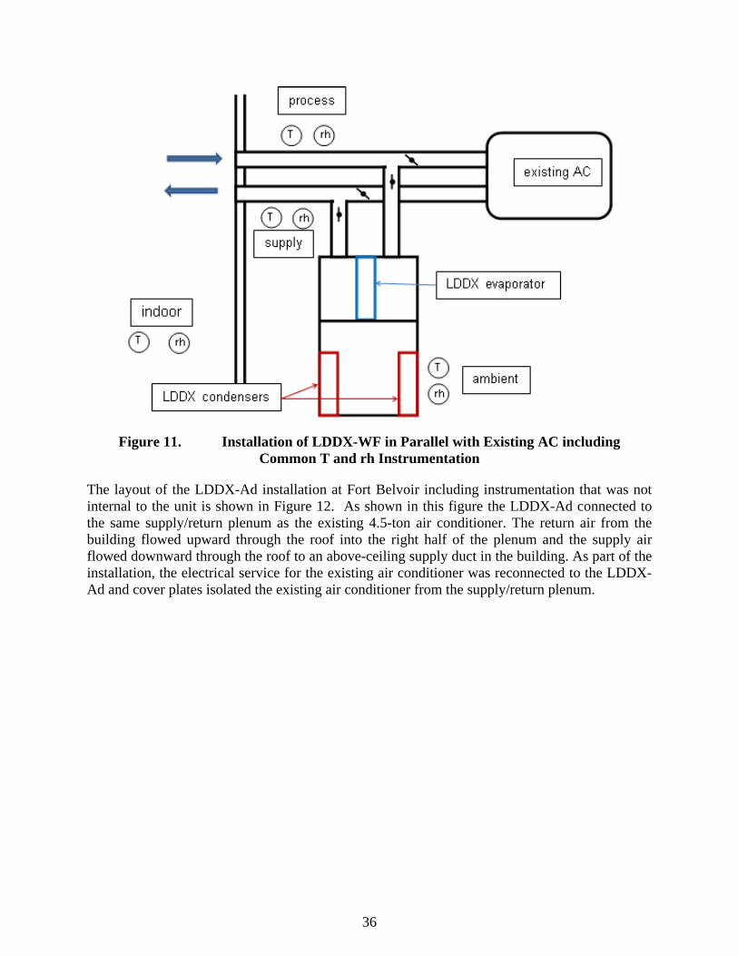
36
Figure 11. Installation of LDDX-WF in Parallel with Existing AC including Common T and rh Instrumentation
The layout of the LDDX-Ad installation at Fort Belvoir including instrumentation that was not internal to the unit is shown in Figure 12. As shown in this figure the LDDX-Ad connected to the same supply/return plenum as the existing 4.5-ton air conditioner. The return air from the building flowed upward through the roof into the right half of the plenum and the supply air flowed downward through the roof to an above-ceiling supply duct in the building. As part of the installation, the electrical service for the existing air conditioner was reconnected to the LDDX-Ad and cover plates isolated the existing air conditioner from the supply/return plenum.
37
Figure 12. Installation of LDDX-Ad in Parallel with Existing AC Including Common T and rh Instrumentation
5.4 OPERATIONAL TESTING
The major phases of operational testing were as follows:
• Steady state performance under controlled laboratory conditions – The LDDX was operated in the AILR flow loop (previously described). The flow loop was controlled so that AHRI test conditions were simulated. LDDX operating parameters, primarily desiccant flow rates to the condenser/desorber and evaporator/absorber, were adjusted so that the LDDX’s cooling capacity and efficiency were mapped as a function of these operating parameters.
• Tuning of control algorithm and system operating functions during commissioning tests in the field – When operating in the field, the LDDX must follow defined sequences for starting its compressor, pumps and fans that avoid possible damaging operating conditions (e.g., operating the LDDX-WF’s refrigeration circuit before stable desiccant flow is established on its evaporator and condenser). Similarly, it must follow defined sequences for shutting down when either it receives a signal that the building’s thermostat/humidistat is satisfied or it receives a fault signal from one if its fault detection elements (e.g., the over-pressure switch in the discharge line of the compressor). During commissioning tests, the operation of the LDDX was closely monitored as the unit was challenged with the likely routine and emergency events that lead to start-up or shutdown. Adjustments were made to the LDDX’s control algorithm as necessary to ensure reliable operation.
38
• Initial field performance under control of building thermostat – In the first phase of monitored field operation the recirculation rate of desiccant over the evaporator/absorber was fixed at a nominal value and the LDDX was operated under the control of the building’s thermostat.
• Operation of the LDDX under conditions that change the Sensible Heat Ratio (SHR) of the supplied cooling – In the second phase of monitored field operation the desiccant flow rates to the absorber and desorber were adjusted to change the concentration of the liquid desiccant circulating over these elements. Changes that produced a weaker desiccant concentration on the absorber reduced the LDDX’s water removal rate leading to a higher SHR for the delivered cooling.
• Operation of a conventional DX air conditioner – As described in Section 5.2, the baseline characterization of the test site when served by a conventional DX air conditioner (or alternately, an LDDX configured to operate as a conventional DX air conditioner) was completed in a third phase of operational testing.
5.5 SAMPLING PROTOCOL
During the start-up phase of the LDDX’s field operation, manual measurements were made of power draws for the unit’s two fans and two desiccant pumps. Manual measurements were also made of the desiccant flows to the evaporator and condenser at the nominal recirculation rate and nominal flow rate of the process air. During all phases of field operation, temperature and humidities previously identified as either independent or dependent variables were sampled at 10 second intervals by a Campbell data logger and stored as one-minute averages. Other data that was continually stored as one-minute averages included: (1) total power, (2) control signal to the LDDX’s desiccant recirculation valve, (3) control signal to LDDX’s variable-speed compressor.
Data collection was continuous throughout the three phases of field operation. Each night 1,440 data records were downloaded via a cellular modem to AILR’s laboratory. This transfer of data occurred automatically during the demonstration field test. Data was screened daily to insure its validity. A copy of the data was stored daily in a cloud-based DropBox folder as protection against loss due to a hardware failure in AILR’s computer network.
Figure 13 shows three graphs of air temperature (top graph), air relative humidity (middle graph) and LDDX electrical power (bottom graph) for September 4, 2015. (The time shown on the x-axis is Greenwich Mean Time, which is four hours ahead of local time.)
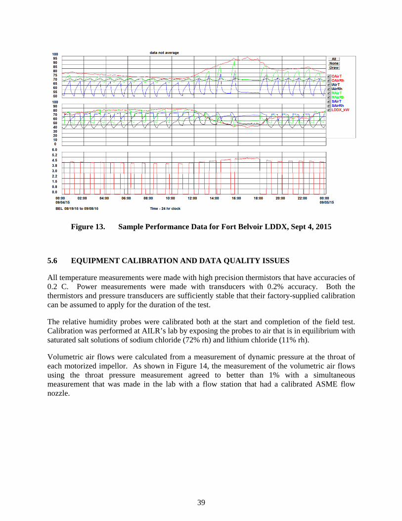
39
Figure 13. Sample Performance Data for Fort Belvoir LDDX, Sept 4, 2015
5.6 EQUIPMENT CALIBRATION AND DATA QUALITY ISSUES
All temperature measurements were made with high precision thermistors that have accuracies of 0.2 C. Power measurements were made with transducers with 0.2% accuracy. Both the thermistors and pressure transducers are sufficiently stable that their factory-supplied calibration can be assumed to apply for the duration of the test.
The relative humidity probes were calibrated both at the start and completion of the field test. Calibration was performed at AILR’s lab by exposing the probes to air that is in equilibrium with saturated salt solutions of sodium chloride (72% rh) and lithium chloride (11% rh).
Volumetric air flows were calculated from a measurement of dynamic pressure at the throat of each motorized impellor. As shown in Figure 14, the measurement of the volumetric air flows using the throat pressure measurement agreed to better than 1% with a simultaneous measurement that was made in the lab with a flow station that had a calibrated ASME flow nozzle.
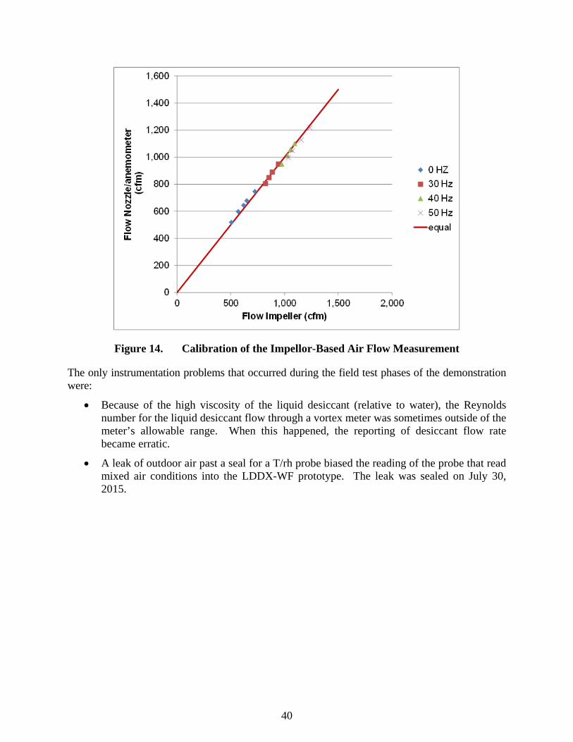
40
Figure 14. Calibration of the Impellor-Based Air Flow Measurement
The only instrumentation problems that occurred during the field test phases of the demonstration were:
• Because of the high viscosity of the liquid desiccant (relative to water), the Reynolds number for the liquid desiccant flow through a vortex meter was sometimes outside of the meter’s allowable range. When this happened, the reporting of desiccant flow rate became erratic.
• A leak of outdoor air past a seal for a T/rh probe biased the reading of the probe that read mixed air conditions into the LDDX-WF prototype. The leak was sealed on July 30, 2015.

41
6.0 PERFORMANCE ASSESSMENT
6.1 LDDX-WF LABORATORY PERFORMANCE
In May 2014, the LDDX-WF prototype was installed in the test loop shown in Figure 9. Following a two-week period during which the basic operation of the prototype, its control and the accuracy of its instrumentation were verified, the performance of the prototype was measured at AHRI A rating conditions10. During these tests the fraction of liquid desiccant that was recirculated over the evaporator was changed so that the prototype’s capability to modulate its Sensible Heat Ratio (SHR) could be studied.
The graph in Figure 15 shows the effect of desiccant recirculation on the LDDX-WF prototype’s performance. (All data points in Figure 15 are five-minute averages taken during steady operation at least 30 minutes after a change had been made to the liquid-desiccant diverting valve. A valve setting of zero corresponds to a once-through desiccant circuit in which all the desiccant flowing off the evaporator is pumped to the condenser and all the desiccant flowing off the condenser is pumped to the evaporator. As the valve setting increases towards a maximum of 90, the fraction of liquid desiccant that flows off the evaporator that is returned to the evaporator increases, which leads to a less concentrated desiccant flowing on the evaporator.)
0.40
0.45
0.50
0.55
0.60
0.65
0.70
0.75
0.80
0
2
4
6
8
10
12
14
40 60 80 100
LHR
EER
, TC
Ton
s, C
ompr
esso
r Pow
er (k
W)
Recirc Valve Position
EER - May 15EER - May 20TC tonsCompressor kWLHR - May 15LHR - May 20
Figure 15. Experimental Performance of the LDDX-WF at AHRI A Rating Conditions (EER is based on compressor power only)
10 The AHRI A rating conditions are 95/75 F and 80/67 F dry-bulb/wet-bulb temperatures for outdoor air and return air respectively.

42
The measured performance shows that the Latent Heat Ratio (LHR – which equals one minus the SHR) varies from about 0.50 to 0.73 when the recirculation valve settings decreases from 90 to 50. (For comparison, the LHR for a conventional, high efficiency DX air conditioner would be on the order of 0.25 at AHRI A rating conditions.) This behavior is expected, since the desiccant that flows over the evaporator becomes weaker as the recirculation rate increase (i.e., the recirculation valve setting increases).
In Figure 15 there is a trend towards lower cooling output (TC tons) and lower EER as the setting of the recirculation valve decreases. This trend is also expected since the temperature of the desiccant supplied to the evaporator increases with decreasing recirculation: the warm desiccant supplied to the evaporator both increases the amount of heat that must be pumped by the compressor and reduces the total cooling supplied to the process air.
As shown in Figure 16, the LDDX-WF prototype supplied air that was much drier than that supplied by a conventional DX air conditioner: the relative humidity of the air supplied by the prototype was between 39% and 43% whereas a conventional DX air conditioner supplies air at close to 100% rh.
30
32
34
36
38
40
42
44
46
48
50
40 50 60 70 80
Dew
poin
t (F)
and
Rel
ativ
e H
umid
ity
Recirc Valve Position
Supply DPSupply rh
Figure 16. Experimental Performance of the LDDX-WF at AHRI A Rating Conditions: Supply Dewpoint and Relative Humidity
The EER shown in Figure 15 is based only on the prototype’s compressor power. Assuming 356 W per 1,000 cfm for the process air fan, 125 W per 1,000 cfm for the cooling fan and 50 W for pump power would reduce the EERs shown in Figure 15 by about 23%.

43
Based on the laboratory tests at AHRI A conditions the LDDX-WF prototype can meet the performance objective shown in Table 1 of supplying air with a dewpoint of 47oF. The laboratory tests also confirmed the prototype’s capacity to modulate its LHR. In Figure 15 an adjustment in the recirculation valve between settings of 50 and 90 changed the LHR from 0.73 to 0.50 (i.e., an SHR change from 0.27 to 0.50). Since it is expected that a valve setting greater than 90 would increase the SHR to a value greater than 0.50, the prototype should be able to satisfy the performance objective of an SHR operating range between 0.35 and 0.65.
Based on its laboratory operation, it is unlikely that LDDX-WF prototype will satisfy the efficiency performance objective listed in Table 1: operation at an EER of 11 and an SHR less than 0.4. As shown in Figure 15, when operating with the recirculation valve set at about 75, the prototype provided cooling with an LHR of 0.60 (i.e., SHR equal to 0.40) with a compressor-based EER of 12. However, when fan and pump power are included, this EER decreases to 9.3.
The May 2014 laboratory operation of the LDDX-WF prototype was the first opportunity to measure heat and mass transfer coefficients for a wicking-fin heat and mass exchanger operating at conditions representative of an LDDX-WF’s evaporator and condenser. The heat and mass transfer coefficients that were inferred from the overall operation of the LDDX significantly deviated from those that were calculated from earlier tests on water-cooled (or water-heated), small-scale models of wicking-fin heat and mass exchangers. In particular, the heat transfer coefficient for the desiccant flowing over the evaporator tubes was only about 75% the value used to design the LDDX-WF prototype, but for the condenser, it was 150%. (The working hypothesis for these differences is now assumed to be changes in desiccant film thickness caused by the change in viscosity of the desiccant: the desiccant viscosity on the low-temperature evaporator tubes is about twice that on the high-temperature condenser tubes.)
With the adjusted heat and mass transfer coefficients, the computer model predicts the LDDX performance labeled as “Current Design” in Figures 17 and 18. The laboratory performance of the LDDX-WF prototype falls considerable below its design level—EER peaked at 9.3 versus a design value of 11.0. The LDDX prototype’s inability to meet its design performance is most likely due to the previously reported unexpectedly lower heat transfer effectiveness between the liquid desiccant and the evaporator tubes.
Both the wicking-fin evaporator and condenser of the LDDX-WF prototype are too small to meet the performance objective for efficiency that is shown in Table 1. As shown in Figures 17 and 18, a 1.5X increase in the face area of both the evaporator and condenser increases the EER of an LDDX-WF air conditioner to a maximum value of 12.0 while maintaining a supply dewpoint of between 46oF and 47oF.
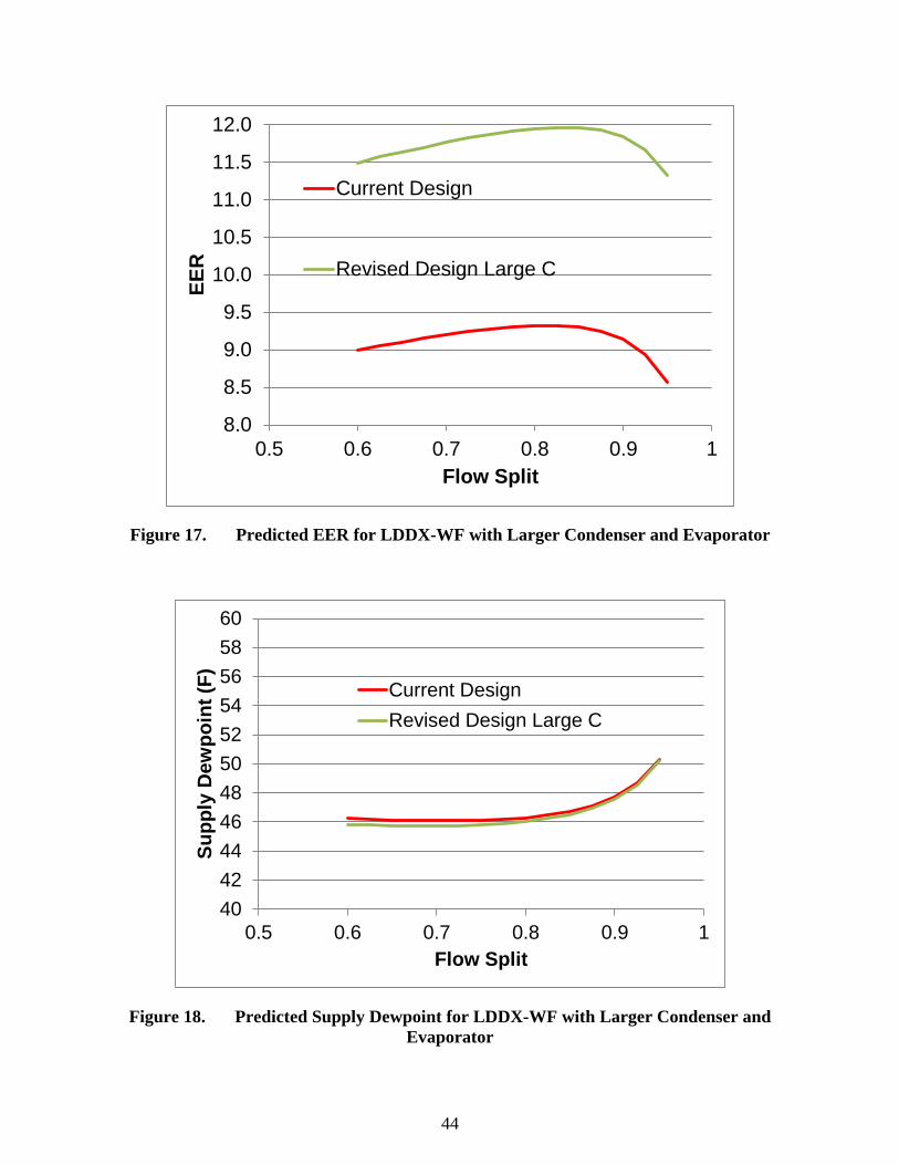
44
8.0
8.5
9.0
9.5
10.0
10.5
11.0
11.5
12.0
0.5 0.6 0.7 0.8 0.9 1
EER
Flow Split
Current Design
Revised Design Large C
Figure 17. Predicted EER for LDDX-WF with Larger Condenser and Evaporator
4042444648505254565860
0.5 0.6 0.7 0.8 0.9 1
Supp
ly D
ewpo
int (
F)
Flow Split
Current DesignRevised Design Large C
Figure 18. Predicted Supply Dewpoint for LDDX-WF with Larger Condenser and Evaporator

45
6.2 LDDX-AD LABORATORY PERFORMANCE
In June 2015, the 5-ton LDDX-Ad prototype was installed in the test loop shown in Figure 9. During a three-week test period, the prototype’s operation at AHRI A rating conditions was documented. The ten test sequences summarized in Table 3 were performed during this laboratory phase of testing. Tests were performed under varied conditions that included: (1) two different liquid desiccants (i.e., lithium chloride and potassium acetate), (2) a nominal and a twice nominal desiccant flow rate, and (3) a pulsed desiccant flow rate.
The red crosses in Figure 19 are the values of SHR and EER for the eight runs in Table 3 that had outdoor air temperatures close to AHRI rating temperature of 95 F. However, since the flow loop for the laboratory tests could not precisely maintain the AHRI A rating conditions, there is a moderate amount of scatter in the data shown in Figure 19. Using a computer model of the LDDX-Ad that closely matched the measured performance of the eight runs shown in Figure 19 the LDDX-Ad was predicted to have an SHR of 0.403 and an EER of 11.46 at the AHRI A rating condition. This predicted value appears as the red circle in Figure 19.
Figure 19 also includes EER/SHR data points for (1) a conventional high efficiency DX air conditioner (12.0/0.76), (2) a DX air conditioner with a low level of reheat (9.29/0.63), and a DX air conditioner with a high level of reheat (5.79/0.45). The LDDX-Ad’s ability to efficiently supply latent cooling is apparent when compared to both DX air conditioners that reheat the process air.
0.35
0.40
0.45
0.50
0.55
0.60
0.65
0.70
0.75
0.80
5.0 7.0 9.0 11.0 13.0 15.0
SHR
EER
DX no reheat
reheat (Manufacturer 1)
reheat (Manufacturer 2)
LDDX modeled as-built
LDDX Test Data
conventional DX with increasing reheat
ARI A Operating Conditions
Figure 19. The Laboratory Performance of the 5-Ton LDDX-Ad
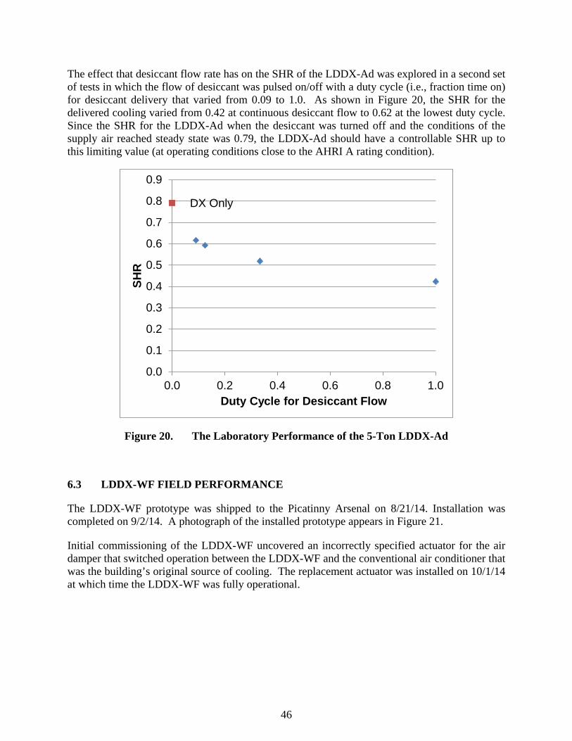
46
The effect that desiccant flow rate has on the SHR of the LDDX-Ad was explored in a second set of tests in which the flow of desiccant was pulsed on/off with a duty cycle (i.e., fraction time on) for desiccant delivery that varied from 0.09 to 1.0. As shown in Figure 20, the SHR for the delivered cooling varied from 0.42 at continuous desiccant flow to 0.62 at the lowest duty cycle. Since the SHR for the LDDX-Ad when the desiccant was turned off and the conditions of the supply air reached steady state was 0.79, the LDDX-Ad should have a controllable SHR up to this limiting value (at operating conditions close to the AHRI A rating condition).
DX Only
0.0
0.1
0.2
0.3
0.4
0.5
0.6
0.7
0.8
0.9
0.0 0.2 0.4 0.6 0.8 1.0
SHR
Duty Cycle for Desiccant Flow
Figure 20. The Laboratory Performance of the 5-Ton LDDX-Ad
6.3 LDDX-WF FIELD PERFORMANCE
The LDDX-WF prototype was shipped to the Picatinny Arsenal on 8/21/14. Installation was completed on 9/2/14. A photograph of the installed prototype appears in Figure 21.
Initial commissioning of the LDDX-WF uncovered an incorrectly specified actuator for the air damper that switched operation between the LDDX-WF and the conventional air conditioner that was the building’s original source of cooling. The replacement actuator was installed on 10/1/14 at which time the LDDX-WF was fully operational.

47
Figure 21. The Installed LDDX-WF Prototype
Unfortunately, the unseasonably cool weather at the test site in October prevented extended operation of the LDDX-WF in 2014.
Following a maintenance visit to the site on May 7, 2015, the LDDX-WF began operation for the 2015 cooling season. An analysis of the LDDX-WF’s performance in early June showed that the unit was short cycling. An adjustment to the unit’s control algorithm to increase the size of the dead band for zone temperature extended the minimum on-time for the unit from less than 10 minutes to over 20 minutes.
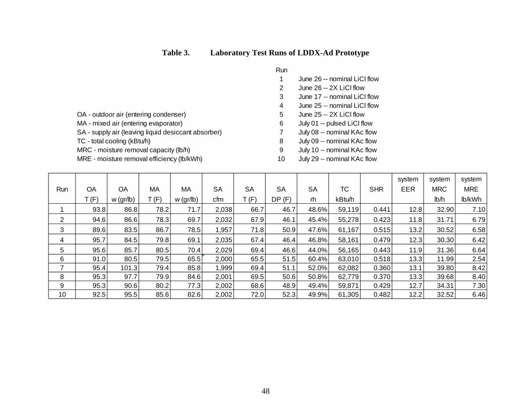
48
Table 3. Laboratory Test Runs of LDDX-Ad Prototype
Run1 June 26 -- nominal LiCl flow2 June 26 -- 2X LiCl flow3 June 17 -- nominal LiCl flow4 June 25 -- nominal LiCl flow
OA - outdoor air (entering condenser) 5 June 25 -- 2X LiCl flowMA - mixed air (entering evaporator) 6 July 01 -- pulsed LiCl flowSA - supply air (leaving liquid desiccant absorber) 7 July 08 -- nominal KAc flowTC - total cooling (kBtu/h) 8 July 09 -- nominal KAc flowMRC - moisture removal capacity (lb/h) 9 July 10 -- nominal KAc flowMRE - moisture removal efficiency (lb/kWh) 10 July 29 -- nominal KAc flow
system system systemRun OA OA MA MA SA SA SA SA TC SHR EER MRC MRE
T (F) w (gr/lb) T (F) w (gr/lb) cfm T (F) DP (F) rh kBtu/h lb/h lb/kWh1 93.8 86.8 78.2 71.7 2,038 66.7 46.7 48.6% 59,119 0.441 12.8 32.90 7.102 94.6 86.6 78.3 69.7 2,032 67.9 46.1 45.4% 55,278 0.423 11.8 31.71 6.793 89.6 83.5 86.7 78.5 1,957 71.8 50.9 47.6% 61,167 0.515 13.2 30.52 6.584 95.7 84.5 79.8 69.1 2,035 67.4 46.4 46.8% 58,161 0.479 12.3 30.30 6.425 95.6 85.7 80.5 70.4 2,029 69.4 46.6 44.0% 56,165 0.443 11.9 31.36 6.646 91.0 80.5 79.5 65.5 2,000 65.5 51.5 60.4% 63,010 0.518 13.3 11.99 2.547 95.4 101.3 79.4 85.8 1,999 69.4 51.1 52.0% 62,082 0.360 13.1 39.80 8.428 95.3 97.7 79.9 84.6 2,001 69.5 50.6 50.8% 62,779 0.370 13.3 39.68 8.409 95.3 90.6 80.2 77.3 2,002 68.6 48.9 49.4% 59,871 0.429 12.7 34.31 7.3010 92.5 95.5 85.6 82.6 2,002 72.0 52.3 49.9% 61,305 0.482 12.2 32.52 6.46
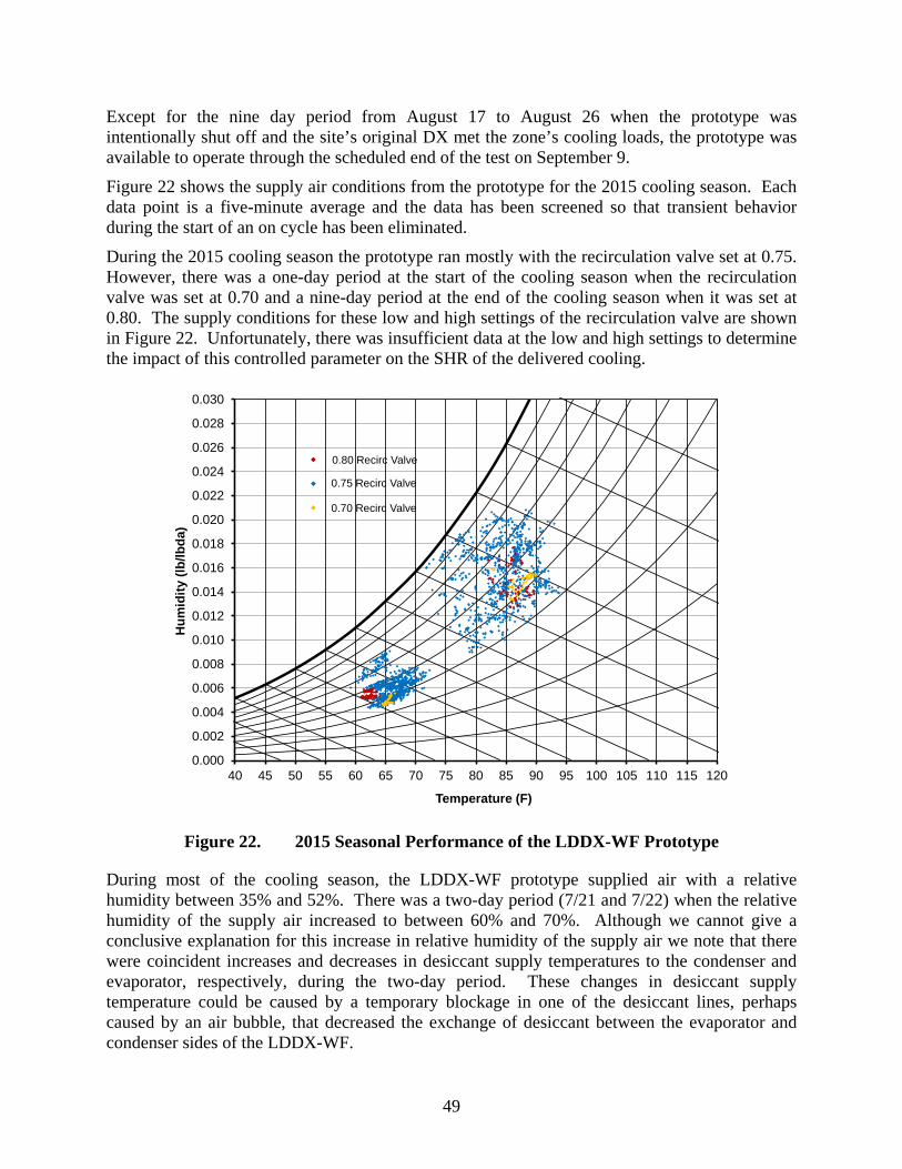
49
Except for the nine day period from August 17 to August 26 when the prototype was intentionally shut off and the site’s original DX met the zone’s cooling loads, the prototype was available to operate through the scheduled end of the test on September 9. Figure 22 shows the supply air conditions from the prototype for the 2015 cooling season. Each data point is a five-minute average and the data has been screened so that transient behavior during the start of an on cycle has been eliminated. During the 2015 cooling season the prototype ran mostly with the recirculation valve set at 0.75. However, there was a one-day period at the start of the cooling season when the recirculation valve was set at 0.70 and a nine-day period at the end of the cooling season when it was set at 0.80. The supply conditions for these low and high settings of the recirculation valve are shown in Figure 22. Unfortunately, there was insufficient data at the low and high settings to determine the impact of this controlled parameter on the SHR of the delivered cooling.
0.80 Recirc Valve
0.75 Recirc Valve
0.70 Recirc Valve
0.000
0.002
0.004
0.006
0.008
0.010
0.012
0.014
0.016
0.018
0.020
0.022
0.024
0.026
0.028
0.030
40 45 50 55 60 65 70 75 80 85 90 95 100 105 110 115 120
Hum
idity
(lb/
lbda
)
Temperature (F)
Figure 22. 2015 Seasonal Performance of the LDDX-WF Prototype
During most of the cooling season, the LDDX-WF prototype supplied air with a relative humidity between 35% and 52%. There was a two-day period (7/21 and 7/22) when the relative humidity of the supply air increased to between 60% and 70%. Although we cannot give a conclusive explanation for this increase in relative humidity of the supply air we note that there were coincident increases and decreases in desiccant supply temperatures to the condenser and evaporator, respectively, during the two-day period. These changes in desiccant supply temperature could be caused by a temporary blockage in one of the desiccant lines, perhaps caused by an air bubble, that decreased the exchange of desiccant between the evaporator and condenser sides of the LDDX-WF.

50
Figure 23 compares the relative humidity of the test zone within the building when the LDDX-WF prototype is operating and when the site’s original DX air conditioner is running. As shown in this figure, the prototype has a relatively modest impact on the zone relative humidity: with the prototype operating the zone relative humidity was close to 45% and with the DX air conditioner operating it was close to 48%.
0
10
20
30
40
50
60
70
30 50 70 90
Indo
or R
elat
ive
Hum
idity
Outdoor Relative Humidity
LDDX OnDX On
Figure 23. The Impact of the LDDX-WF on Indoor RH
It is likely that the interior layout and HVAC zoning of the test site (Building 407) is masking the impact of the LDDX-WF on indoor comfort. The side of Building 407 where the LDDX-WF is sited has five other pad-mounted air conditioners. The zones served by these air conditioners all abut on a large common corridor. When doors to the zones are open, there will be a significant amount of mixing between zones that reduces the impact of the LDDX-WF on the zone where indoor measurements are made.
6.4 LDDX-AD FIELD PERFORMANCE
The LDDX-Ad prototype was shipped to the Fort Belvoir on 8/17/15. Installation was completed on 8/18/15. A photograph of the installed prototype appears in Figure 24.
Figure 24. The Installed LDDX-Ad Prototype
51
During a routine maintenance visit to the site on Sept 11, the AILR technician noted that the liquid-desiccant desorber pad (i.e., the pad behind the condenser coil) had settled slightly and was less securely captured by the flanges of the desiccant distributor (compared to the original installation). It was not possible to correct the problem during the Sept 11 visit and a decision was made to continue operation. On September 21, the Fort Belvoir facilities manager received a report of an unusual noise originating from the HVAC system at Building 392. Inspection of the LDDX-Ad prototype showed that a section of the liquid-desiccant desorber pad had become disengaged from the desiccant distributor. Since the cooling season was near its end and the repair work to restore the prototype to full function was extensive, a decision was made to take the prototype off-line and return the site’s original air heat pump to operation.
During the 2015/2016 winter, work was performed to correct the problem that led to the failure of the LDDX-Ad’s desorber pad. The source of the problem was the incompatibility between the corrugated fiberglass contact media used in the desorber pad and the solution of potassium acetate that functioned as the liquid desiccant. An inspection of the failed desorber showed that the potas-sium acetate was dissolving/attacking the binder used for the fiberglass and softening the pad.
We set up an exposure test in which small samples of contact media were continuously flooded with liquid desiccant while under a compressive load. The height of each sample was periodically measured. The measured compression of the pad was used as the metric that indicated that the liquid desiccant was weakening the contact media.
Four samples of contact media were installed in the exposure test rig. One sample was the media that had failed in the LDDX-Ad prototype. Two of the other three samples also used a corrugated fiberglass media, but with alternative binders, and the third sample used a non-woven, corrugated polyester media.
During an eight-week exposure test, one of the three samples experienced essentially no compression. (For comparison, the contact media that had failed in the prototype was compressed 20%.) This media was made from corrugated fiberglass, but with a different binder. (Unfortunately, binders are treated as trade secrets by manufacturers, and so it was not possible to get a meaningful description of them from the manufacturers.)
A new desorber pad was made from the contact media that had passed the exposure test. AILR staff was on-site at Fort Belvoir on May 18/19 and May 31/June1 to install the new desorber pad and start up the prototype for summer operation. The work proceeded with no problems and data collection on the prototype’s performance commenced following the May 31/June 1 visit.
The LDDX-Ad prototype operated under the command of the zone’s thermostat continually from June 1 through September 27. (The prototype does not have a heating function. By late September Building 392 required heat in the early morning, which could only be provided by reinstalling the original DX heat pump.)
Figure 25 shows the supply air conditions from the prototype for the 2016 cooling season. Each data point is a five-minute average and the data has been screened so that transient behavior during the start of an on-cycle has been eliminated. Data is shown in this figure for the outdoor air, mixed air into the LDDX-Ad and supply air from the LDDX-Ad.
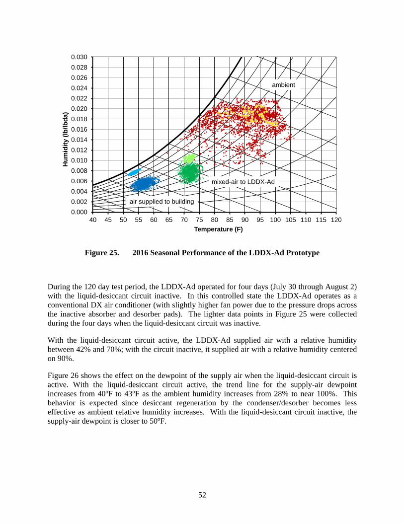
52
0.0000.0020.0040.0060.0080.0100.0120.0140.0160.0180.0200.0220.0240.0260.0280.030
40 45 50 55 60 65 70 75 80 85 90 95 100 105 110 115 120
Hum
idity
(lb/
lbda
)
Temperature (F)
mixed-air to LDDX-Ad
air supplied to building
ambient
Figure 25. 2016 Seasonal Performance of the LDDX-Ad Prototype
During the 120 day test period, the LDDX-Ad operated for four days (July 30 through August 2) with the liquid-desiccant circuit inactive. In this controlled state the LDDX-Ad operates as a conventional DX air conditioner (with slightly higher fan power due to the pressure drops across the inactive absorber and desorber pads). The lighter data points in Figure 25 were collected during the four days when the liquid-desiccant circuit was inactive.
With the liquid-desiccant circuit active, the LDDX-Ad supplied air with a relative humidity between 42% and 70%; with the circuit inactive, it supplied air with a relative humidity centered on 90%.
Figure 26 shows the effect on the dewpoint of the supply air when the liquid-desiccant circuit is active. With the liquid-desiccant circuit active, the trend line for the supply-air dewpoint increases from 40oF to 43oF as the ambient humidity increases from 28% to near 100%. This behavior is expected since desiccant regeneration by the condenser/desorber becomes less effective as ambient relative humidity increases. With the liquid-desiccant circuit inactive, the supply-air dewpoint is closer to 50oF.
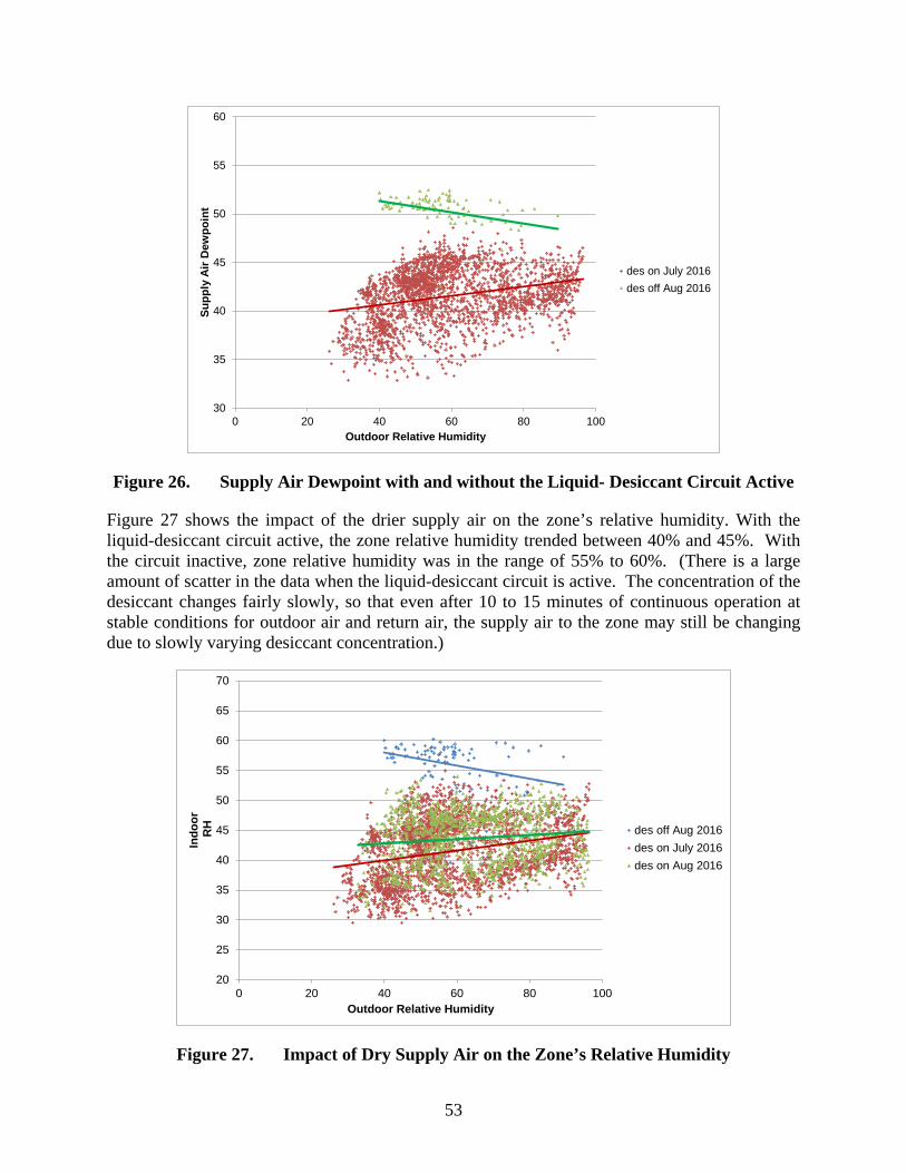
53
30
35
40
45
50
55
60
0 20 40 60 80 100
Supp
ly A
ir D
ewpo
int
Outdoor Relative Humidity
des on July 2016des off Aug 2016
Figure 26. Supply Air Dewpoint with and without the Liquid- Desiccant Circuit Active
Figure 27 shows the impact of the drier supply air on the zone’s relative humidity. With the liquid-desiccant circuit active, the zone relative humidity trended between 40% and 45%. With the circuit inactive, zone relative humidity was in the range of 55% to 60%. (There is a large amount of scatter in the data when the liquid-desiccant circuit is active. The concentration of the desiccant changes fairly slowly, so that even after 10 to 15 minutes of continuous operation at stable conditions for outdoor air and return air, the supply air to the zone may still be changing due to slowly varying desiccant concentration.)
20
25
30
35
40
45
50
55
60
65
70
0 20 40 60 80 100
Indo
orRH
Outdoor Relative Humidity
des off Aug 2016des on July 2016des on Aug 2016
Figure 27. Impact of Dry Supply Air on the Zone’s Relative Humidity

54
As noted earlier, an active liquid-desiccant circuit does penalize efficiency by transferring heat rejected by the condenser to the supply air. A computer model of the LDDX-Ad predicts about a 5% drop in EER due to “heat dump” under conditions typical of operation at Fort Belvoir. However, as shown in Figure 28, there is about a 15% drop in EER when the liquid-desiccant circuit is active. This larger drop in efficiency is due to the fact that with the liquid-desiccant circuit active the room humidity decreases as does the return air that the LDDX-Ad processes. With drier, lower enthalpy air entering the evaporator, the suction temperature of the refrigerant circuit decreases and the compressor power increases. For the data shown in Figure 28, the LDDX-Ad with an active liquid-desiccant circuit has a suction temperature that is about 3.5oF lower than when the circuit is inactive. This drop in suction temperature accounts for about eight of the 15 point drop in EER that is shown in Figure 28.
0
2
4
6
8
10
12
14
16
65 70 75 80 85 90 95 100 105
EER
Outdoor Drybulb (F)
des on July 2016des off Aug 2016
Figure 28. LDDX-Ad’s EER with and without the Liquid-Desiccant Circuit Active
6.5 MAINTENANCE ISSUES & PROTOTYPICAL DESIGN WEAKNESSES
During field operation site visits were made about once every four to six weeks at both Picatinny Arsenal and Fort Belvoir to inspect the prototypes. During these visits, air filters were replaced.
A number of other maintenance problems were addressed during the site visits. However, all these problems can be traced back to aspects of the prototypical designs that will be changed in future prototypes.
6.5.1 Picatinny Arsenal
• Desiccant dripped from the tube delivering desiccant to the evaporator; the desiccant splashed onto the floor of the LDDX and onto the soldered joints of the evaporator’s u-bends causing corrosion of these joints.
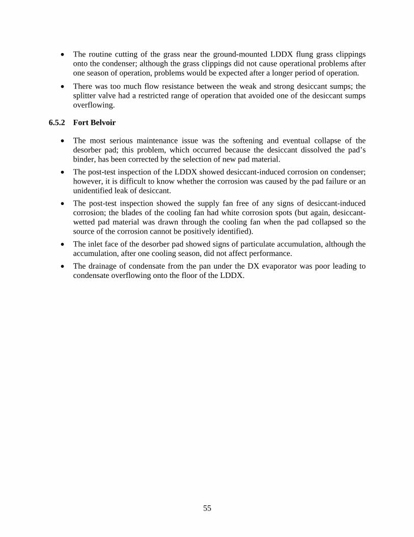
55
• The routine cutting of the grass near the ground-mounted LDDX flung grass clippings onto the condenser; although the grass clippings did not cause operational problems after one season of operation, problems would be expected after a longer period of operation.
• There was too much flow resistance between the weak and strong desiccant sumps; the splitter valve had a restricted range of operation that avoided one of the desiccant sumps overflowing.
6.5.2 Fort Belvoir
• The most serious maintenance issue was the softening and eventual collapse of the desorber pad; this problem, which occurred because the desiccant dissolved the pad’s binder, has been corrected by the selection of new pad material.
• The post-test inspection of the LDDX showed desiccant-induced corrosion on condenser; however, it is difficult to know whether the corrosion was caused by the pad failure or an unidentified leak of desiccant.
• The post-test inspection showed the supply fan free of any signs of desiccant-induced corrosion; the blades of the cooling fan had white corrosion spots (but again, desiccant-wetted pad material was drawn through the cooling fan when the pad collapsed so the source of the corrosion cannot be positively identified).
• The inlet face of the desorber pad showed signs of particulate accumulation, although the accumulation, after one cooling season, did not affect performance.
• The drainage of condensate from the pan under the DX evaporator was poor leading to condensate overflowing onto the floor of the LDDX.

56
Page Intentionally Left Blank

57
7.0 COST ASSESSMENT
In HVAC applications, the LDDX provides greatest value in applications where latent loads—either internal, external, or both—are high. The conventional approach to maintaining comfortable indoor conditions in these high-latent applications is to over-cool the supply air to reduce its dewpoint and then to reheat the supply air so that the indoor dry-bulb temperature stays in a comfortable range.
Over-cool/reheat can significantly increase HVAC costs: it both requires an over-sized cooling system (i.e., its capacity must meet the design day cooling loads plus the reheat that is simultaneously applied), and demands more total cooling from the system. Although for most applications today comfortable indoor can be maintained without over-cooling/reheat (at least in theory for a well-designed, properly operated HVAC system), expected changes in building technology as well as changes in how people work will increase the need for HVAC systems that more efficiently provide latent cooling.
7.1 COST MODEL
7.1.1 Space Conditioning for Comfort The economics of owning an LDDX depend on how the LDDX is applied. In an application such as comfort cooling, the primary cost elements entering into a purchasing decision are the hardware capital cost, installation cost and cost for consumables (i.e., primarily gas and electricity) Maintenance and other non-utility operating costs can influence the purchasing decision, but typically they are of secondary importance. And, despite research showing a strong link between indoor space conditions and worker health and productivity, “comfort” is rarely given an economic value when purchasing HVAC systems for comfort cooling.
Today, for many applications where comfort is the primary goal, indoor temperature and humidity can be acceptably controlled without over-cooling and reheating the supply air. To illustrate this point, consider an interior office zone where the primary internal loads are lighting, office equipment (i.e., plug loads) and people. With the following assumptions for an interior zone (i.e., minimal envelope and solar loads) with an “open” office plan11,12:
zone temperature setpoint: 75 Fo 13 ventilation rate: 5 cfm per person lighting load: 1.11 W/ft2 plug load: 0.81 W/ft2 occupant density: 5 people per 1,000 square feet latent load per person: 155 Btu/h (typical of seated, light office work) sensible load per person: 245 Btu/h (typical of seated, light office work) supply air conditions: saturated at 55 Fo,
the office will “float” at 51% relative humidity, which is well within the ASHRAE comfort zone. 11 ASHRAE Handbook Fundamentals, 2013 12 ANSI/ASHRAE Standard 62.1-2004. 13 “Facilities Standards for the Public Buildings Service”, Table 5.1, 2005.
58
The future evolution of the office will most likely move in a direction that reduces sensible loads and increases latent loads. In particular, the following trends have started and are likely to continue:
• LED technology is reducing the sensible load for lighting • Flat-panel displays and lap-top computers are reducing the sensible load for office
equipment • Partitioned office space is producing occupant densities much higher than 5 people per
1,000 square feet • The recognition that sedentary work styles have an adverse effect on health is leading to
more active work styles. For the following changes to the preceding assumptions for an interior office zone:
lighting load: 0.63 W/ft2 plug load: 0.31 W/ft2 occupant density: 13.3 people per 1,000 square feet latent load per person: 275 Btu/h sensible load per person: 275 Btu/h,
the office will “float” at 61%. Although this value of relative humidity is near the upper limit of the ASHRAE comfort zone, it is being maintained without the inefficiency of overcooling/reheating the supply air. Furthermore, since there is now no economic incentive to keep indoor relative humidity at lower levels, it is unlikely that any cooling technology that provides an enhanced latent capacity will successfully compete in this broad segment of the comfort cooling market.
7.1.2 Solving Building Humidity Problems
Despite the preceding simplified analysis showing that a very large segment of the HVAC market—comfort conditioning of office buildings—can efficiently maintain indoor comfort using conventional means, the LDDX still has the potential to significantly reduce operating and maintenance in DOD buildings. Using Fort Belvoir as an example, Mr. William Elliott (Master Planner, Facilities and Energy) reported that for the 38 buildings under his management, five buildings have sections where high humidity is causing maintenance or operational problems. As a rough estimate, approximately 5% of the floor space under his management would benefit from the LDDX or other humidity control technology.
In “humidity critical” applications similar to those identified by Mr. Elliott, the magnitude of the potential savings for the LDDX-Ad can be estimated by comparing the Moisture Removal Efficiency (MRE—expressed as pounds per hour of moisture removal per kilowatt of power) when both the LDDX-Ad and a conventional overcool/reheat DX air conditioner supply 45oF dewpoint air. In this comparison, the conventional DX air conditioner supplies nearly saturated air at 45oF (which may or may not be reheated). The LDDX-Ad supplies 45oF dewpoint air by first cooling the supply air to saturated conditions at 53oF in its evaporator stage and then near-adiabatically drying the air to 50% rh and 64.5oF (i.e., a 45oF dewpoint) in its desiccant stage.

59
Assuming that both cooling systems operate with a suction temperature that is 12oF below the air temperature leaving their evaporator and they both operate at a 105oF condensing temperature (which might correspond to an ambient between 85oF and 90oF), the compressor-based EER for the LDDX-Ad and the conventional DX air conditioner will be 16.4 and 14.1 respectively.
The lower compressor efficiency is only one of two important parameters that determine the cooling system’s MRE. The conventional DX air conditioner pumps more heat than the LDDX-Ad when it cools air to saturated conditions at 45oF (as opposed to the 53oF air leaving the evaporator stage of the LDDX-Ad). In this example, the DX air conditioner pumps 1.47 times more heat than the LDDX-Ad when both system supply air at a 45oF dewpoint14. When the lower compressor-based EER is combined with the conventional DX air conditioner’s requirement to pump more heat, the LDDX-Ad is calculated to lower the electrical power for cooling in high latent applications by 41.5%.
Thus, for an application where humidity problems within a building must be corrected the economics of ownership are likely to steer the purchasing decision towards the LDDX-Ad. While the LDDX-Ad will have a higher first cost when expressed in terms of dollars per compressor tons, an application in need of humidity control is likely to need fewer gross tons of cooling when the LDDX-Ad is installed compared to a conventional overcool/reheat air conditioner, i.e., as illustrated in the preceding example, the conventional air conditioner might be specified at 1.47 times higher compressor tons to make up for cooling lost to reheat. As previously noted, the core of the LDDX-Ad is a conventional DX air conditioner. The liquid-desiccant circuit that is incorporated into the unit is not a major item on the LDDX-Ad’s bill of materials. Perhaps the biggest impact on selling price will be the higher profit margins demanded by manufacturers that accept the risk of marketing a new HVAC technology.
The field tests did not uncover any maintenance requirements that could not be met by the routine servicing now performed by HVAC contractors (i.e., the replacement of air filters is the most important maintenance requirement). Neither the contact media nor the liquid desiccant is now expected to need routine replacement, and there was no detectable degradation in performance due to possible changes in the contact media. However, the one-year duration of the field test is obviously too short to identify all possible degradation mechanisms within the LDDX-Ad. The OEM costs of the corrugated media and the liquid desiccant charge in the 5-ton LDDX-Ad prototype that was tested at Fort Belvoir are approximately $300 and $190, respectively. Allowing for a 50% mark-up by a service contractor and a $300 labor charge, a complete replacement of media and desiccant would cost approximately $1,000. Replacement of the media and the liquid desiccant if required every three years should not be a major factor in a decision to purchase the LDDX-Ad.
7.1.3 Mitigating Corrosion Damage of Stored Material
The Air Force spends $4.5 billion annually on aircraft maintenance related to corrosion. The source of this corrosion frequently is airborne chlorides that settle on metal parts and sensitive avionics and then absorb moisture from the air to create an electrolyte that promotes galvanic corrosion. Thus, a comprehensive approach to protecting stored material from corrosion must both limit the ambient relative humidity and filter chloride particles from the air. 14 This calculation assumes that air enters the cooling system at 80oF and 50% rh.
60
A Corrosion Mitigation System (CMS) based on dehumidification must keep storage areas at a relative humidity significantly lower than that required for indoor comfort (i.e., 30% to 40% versus 50% to 60%). In a parallel project funded under the DOD SBIR program15, AIL Research is exploring ways that a liquid desiccant air conditioner that operates on the same principles as LDDX-Ad can lower the cost for supplying deeply dried air either directly to parked aircraft or to shelters where aircraft and Aerospace Ground Equipment (AGE) are stored.
An aircraft shelter that is kept at 78oF and 35% rh has an indoor dewpoint of 48oF. A cooling system that pressurized the shelter with ambient air that has been dried to a 45oF dewpoint should meet the requirements of this shelter.
As previously discussed, the LDDX-Ad much more efficiently supplies air at 45oF dewpoint than a conventional DX air conditioner that dehumidifies by overcooling: the LDDX-Ad is calculated to lower the electrical power in this application by 41.5%. Also, since the compressor tonnage is significantly less for the LDDX-Ad (i.e., the conventional DX air conditioner has 1.47 times the compressor tonnage), the first cost for the two options will be comparable. The LDDX-Ad, once commercially available, would be an important part of corrosion mitigation strategy based on tight humidity control of storage facilities.
7.2 COST DRIVERS
With non-utility O&M requirements/costs projected to be similar to those of conventional DX air conditioners, the most important drivers influencing the adoption of the LDDX will be (1) first cost and (2) utility operating costs. As previously discussed, in applications with high latent loads, the LDDX’s ability to serve the latent loads with significantly less compressor tonnage will lead to first-cost savings that counter possible higher first costs attributed to either (1) the technologies increased complexity (i.e., the LDDX requires a liquid desiccant subsystem) or (2) the higher profit margins demanded by the manufacturer of the novel technology.
It is likely that early sales to DOD of the LDDX will not be driven solely by the need for improved indoor comfort (i.e., the option to allow indoor workspaces to float at a relative humidity at or above the ASHRAE-defined comfort range will always be the lowest cost option). However, when high indoor humidity leads to building maintenance problems associated with mold and mildew or when high indoor humidity adversely affects the operation of a laboratory, then an investment in the LDDX can be justified.
Perhaps the most important, broad driver for the adoption of the LDDX by DOD will be the need to control corrosion by storing material in drier environments. In this application, it is likely that the first cost and operating cost for the LDDX will be small compared to the reduced maintenance needs or the economic impact of failures in sensitive avionics caused by corrosion.
15 “Liquid Desiccant System for Combined Humidity and Chloride Control,” SBIR Phase II Contract No. FA8501-16-C-0003.
61
7.3 COST ANALYSIS AND COMPARISON
The work reported here has advanced the LDDX technology from a Technology Readiness Level (TRL) of 5 to TRL 7. At this TRL, the prototypes that were field operated, while fully functional, were not manufacturable designs. And, although AILR is now working with a manufacturer to build and test a prototype that is based on a manufacturable design, this prototype is not scheduled to operate in the field until June 2017. At TRL 7, it is not possible to project a meaningful selling price for the LDDX. And, without a meaningful selling price, it is not possible to complete a life-cycle cost analysis as outlined by Handbook 13516.
16 “Life-Cycle Costing Manual for the Federal Energy Management Program”, Handbook 135

62
Page Intentionally Left Blank

63
8.0 IMPLEMENTATION ISSUES
The engineers that specify HVAC equipment are extremely risk averse. This aversion is understandable since the consequences of equipment outage in terms of lost work or process disruptions can be quite severe.
The LDDX, with its reliance on a liquid desiccant, will be viewed as a risky technology within the HVAC industry. And, whether or not this assessment of the LDDX is fair, it will be supported by past failures of two different companies to commercialize a compressor-based, liquid-desiccant air conditioner. These two companies—DryKor and Advantix—both aggressively sold liquid desiccant air conditioners, a significant number of which either had operational problems or did not perform as specified. When both companies ceased operation, they left their customers with liquid-desiccant air conditioners that had no support for servicing.
AILR is now working with a manufacturer of dehumidifiers to field operate a 6,000-cfm LDDX-Ad prototype that will be designed and built by the manufacturer. This prototype is sufficiently different from the DryKor and Advantix technology that the problems experienced by the earlier technology should not affect the prototype. Perhaps more importantly, the manufacturer has a sufficiently large presence in the HVAC industry that possible customer concerns regarding product support and product reliability will not discourage sales.

64
Page Intentionally Left Blank
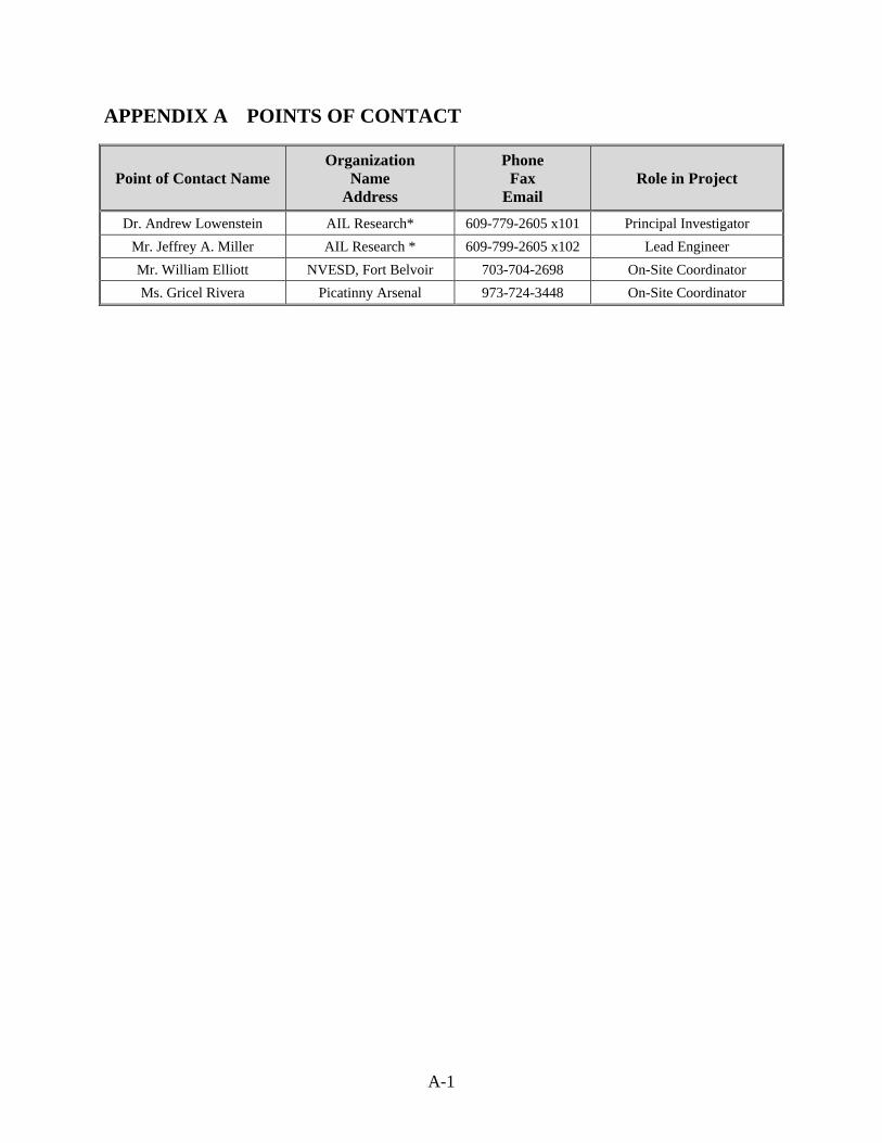
A-1
APPENDIX A POINTS OF CONTACT
Point of Contact Name Organization
Name Address
Phone Fax
Email Role in Project
Dr. Andrew Lowenstein AIL Research* 609-779-2605 x101 Principal Investigator Mr. Jeffrey A. Miller AIL Research * 609-799-2605 x102 Lead Engineer Mr. William Elliott NVESD, Fort Belvoir 703-704-2698 On-Site Coordinator Ms. Gricel Rivera Picatinny Arsenal 973-724-3448 On-Site Coordinator