Embed Size (px)
Citation preview
This report was prepared by Geosyntec Consultants Inc., under contract to the Canadian Council of Ministers of the Environment (CCME). It contains information which has been prepared for, but not approved by, CCME. CCME is not responsible for the accuracy of the information contained herein and does not warrant, or necessarily share or affirm, in any way, any opinions expressed therein. © Canadian Council of Ministers of the Environment 2009
Prepared for
Canadian Council of Ministers of the Environment
Final
Scoping Assessment of Soil Vapour Monitoring Protocols for Evaluating
Subsurface Vapour Intrusion into Indoor Air
Prepared by
130 Research Lane, Suite 2
Guelph. Ontario N1G 5G3
Project Number TR0290
PN 1427 July 8, 2008
EXECUTIVE SUMMARY
In the past decade, awareness of the vapour intrusion pathway has increased following several high profile cases in the United States involving large numbers of residential properties. Over 20 new regulatory guidance documents related to vapour intrusion assessment and mitigation have been developed in different states and provinces. However, there are substantial differences in
the approaches taken in different jurisdictions for assessing vapour intrusion.
Vapour intrusion assessments often require the collection of samples from different media (e.g., indoor air, outdoor air, sub-slab gas, soil gas). Of these media, soil gas samples are less likely than indoor air samples to be significantly affected by background interferences that can confound the interpretation of indoor air sample results; therefore, soil gas sampling is often a critical component of a vapour intrusion assessment. However, collection of soil gas samples is considerably more difficult that the collection of indoor air samples, and there are widely differing protocols for soil gas sampling and analysis. Additionally, the level of detail provided in many guidance documents for the collection of soil gas samples is limited, so individual
practitioners may employ modified methods which result in further differences in methodologies.
Consequently, CCME commissioned this study to develop a summary of several guidance documents in order to better understand the scope of the different soil gas sampling methodologies. A detailed review of Canadian documents provided by the CCME and several additional guidance documents selected by Geosyntec were included in the summary. A comparison in tabular form was made of the various components of soil gas monitoring with
recommendations for each component provided based on Geosyntec’s expertise and experience.
Based on this review, it is clear that no one guidance document includes all the necessary information, level of detail and/or flexibility that are required to assess vapour intrusion at the many different site conditions that a site professional may encounter in Canada. Therefore, it is recommended that CCME complete one of the following options: endorse several different documents to provide the flexibility required by site professionals for assessing many different site conditions; write a new, more comprehensive guidance document; write a companion document to the endorsed documents identifying those discrepancies that result in low quality data; or compile recommendations from this document into a procedure that still allows the site
professional to use elements from the endorsed documents as appropriate.
TR0290B i 2008.07.08 Vapour Scoping 1427.doc
SOMMAIRE
Au cours de la dernière décennie, la sensibilisation à l’intrusion de contaminants volatils a beaucoup augmenté à la suite de plusieurs cas hautement médiatisés survenus aux États-Unis et qui concernaient de nombreuses propriétés résidentielles. Plus d’une vingtaine de nouveaux documents d’orientation réglementaire liés à l’évaluation et l’atténuation de l’intrusion de contaminants volatils ont été rédigés dans divers États et provinces. Toutefois, il existe des différences substantielles dans les approches utilisées par chaque instance pour évaluer l’intrusion de contaminants volatils.
L’évaluation de l’intrusion de contaminants volatils nécessite souvent de recueillir différents échantillons (p. ex : air intérieur, air extérieur, gaz sous dalle, gaz du sol). De ces échantillons, ceux du gaz du sol sont moins susceptibles que ceux de l’air intérieur d’être considérablement influencés par des effets de fond qui peuvent fausser l’interprétation des résultats provenant des échantillons d’air intérieur; c’est pourquoi l’échantillonnage de gaz du sol représente souvent un élément d’importance capitale pour évaluer l’intrusion de contaminants volatils. Cependant, l’échantillonnage du gaz du sol est beaucoup plus difficile que celui de l’air intérieur, et les protocoles d’échantillonnage et d’analyse du gaz du sol varient grandement. De plus, le niveau de détail offert par de nombreux documents d’orientation sur l’échantillonnage du gaz du sol est assez bas; c’est pourquoi chaque évaluateur peut utiliser des méthodes modifiées qui risquent d’accentuer les différences entre les méthodologies.
Le CCME a donc commandé cette étude afin que soit compilé un sommaire de plusieurs documents d’orientation, ce qui permettrait de mieux comprendre la portée des différentes méthodes d’échantillonnage des gaz du sol. Un examen détaillé de documents canadiens fournis par le CCME et de plusieurs autres documents d’orientation sélectionnés par Geosyntec a été inclus dans le sommaire. Une comparaison des divers éléments de la surveillance des gaz du sol a été présentée sous forme de tableau et accompagnée de recommandations basées sur l’expertise et l’expérience de Geosyntec.
Selon cet examen, il est clair qu’aucun document d’orientation ne comporte à lui seul la totalité de l’information, du niveau de détail et/ou de la souplesse nécessaires pour évaluer l’intrusion de contaminants volatils dans les diverses conditions qu’un évaluateur de site professionnel peut rencontrer au Canada. Ainsi, il est recommandé que le CCME choisisse l’une des options suivantes : approuver plusieurs documents offrant aux professionnels la souplesse nécessaire pour l’évaluation de sites dans différentes conditions; rédiger un nouveau document d’orientation plus exhaustif; rédiger un document d’accompagnement pour les documents approuvés qui soulignerait les divergences qui risquent de mener à des résultats de mauvaise qualité; réunir les recommandations du présent document pour produire une procédure qui permettrait aux évaluateurs de continuer à utiliser correctement des éléments des documents approuvés.
TR0290B ii 2008.07.08 Vapour Scoping 1427.doc
TABLE OF CONTENTS
1. INTRODUCTION .....................................................................................................................1
2. COMPARISON BETWEEN SELECTED GUIDANCE DOCUMENTS ................................2
3. SOIL GAS MONITORING PROGRAM DESIGN ..................................................................4 3.1 Soil Gas Probes Spacing and Number of Sample Rounds................................................5
3.2 Representative Soil Vapour Sampling ..............................................................................6
3.3 Soil Gas Probe Depth........................................................................................................6
4. SOIL GAS MONITORING METHODS...................................................................................8 4.1 Geologic Characterization ................................................................................................8
4.2 Soil Gas Probe Design ......................................................................................................8
4.3 Soil Gas Probe Installation................................................................................................9
4.4 Probe Development.........................................................................................................10
4.5 Leak Testing....................................................................................................................11
4.5.1 Shut-in Test.........................................................................................................11 4.5.2 Tracer Testing .....................................................................................................11
4.6 Purging and Field Screening...........................................................................................12
4.7 Pressure Differential and Pneumatic Testing..................................................................14
4.8 Soil Gas Sample Collection ............................................................................................15
4.8.1 Passivated Stainless-Steel Canisters ...................................................................16 4.8.2 Tedlar™ Bags .....................................................................................................16 4.8.3 Glass Bulbs .........................................................................................................17 4.8.4 Syringes...............................................................................................................17 4.8.5 Adsorptive Media................................................................................................17
4.9 Quality Assurance/Quality Control (QA/QC) ................................................................18
5. ANCILLARY METHODS ......................................................................................................19 5.1 Soil Gas Sample Collection from Existing Groundwater Wells.....................................19
5.2 Large-Scale Pneumatic Testing ......................................................................................19
5.3 Flux Chambers ................................................................................................................20
5.4 Meteorological Monitoring.............................................................................................20
6. CONCLUSIONS AND RECOMMENDATIONS ..................................................................21
7. REFERENCES ........................................................................................................................23
TR0290B iii 2008.07.08 Vapour Scoping 1427.doc
LIST OF TABLES
Table 1: Comparison of Vapour Intrusion Guidance Documents Table 2: Soil Gas Probe Spacing and Number of Sample Rounds Table 3: Soil Gas Probe Depth Table 4: Methods of Geologic Characterization Table 5: Soil Gas Probe Construction Table 6: Soil Gas Probe Materials Table 7: Soil Gas Probe Seals Table 8: Soil Gas Probe Development Methods Table 9: Drilling Methods and Equilibrium Time Prior to Sample Collection Table 10: Leak Testing Table 11: Field Screening and Mobile Laboratory Testing Table 12: Measurements of Flow and Vacuum and Pneumatic Testing Table 13: Soil Gas Sample Collection Methods Table 14: Alternative Sample Collection Methods Table 15: Sample Media and Hold Times Table 16: Quality Assurance and Quality Control Table 17: Soil Gas Sample Collection from Existing Groundwater Wells Table 18: Ancillary Methods
TR0290B iv 2008.07.08 Vapour Scoping 1427.doc
TR0290B v 2008.07.08 Vapour Scoping 1427.doc
LIST OF ABBREVIATIONS
ATD Automatic Thermal Desorption CCME Canadian Council of Ministers of the Environment CH4 methane CO2 carbon dioxide DQO data quality objective FID flame ionization detector ft feet GC gas chromatograph in-H2O inches of water column in-Hg inches of mercury ITRC Interstate Technology Regulatory Council L liters L/min liters per minute min minute mL/min milliliters per minute O2 oxygen PARCC precision, accuracy, representativeness, completeness, comparability PID photoionization detector ppbv parts per billion by volume ppmv parts per million by volume QA/QC quality assurance/quality control RBCA Risk-Based Corrective Action SVOC semi-volatile organic compound μg/m3 micrograms per cubic meter VOC volatile organic compound VOST Volatile Organic Sampling Train % percent %v/v percent by volume
1 INTRODUCTION
This document was prepared for the Canadian Council of Ministers of the Environment (CCME) by Geosyntec Consultants, Inc. to provide a comparison of existing guidance documents and to provide recommendations for the collection of soil gas samples, particularly for assessing the
potential for human health risks associated with subsurface vapour intrusion to indoor air.
Soil gas sampling and analysis has been used to assess methane near landfills and the presence or absence of volatile organic compounds (VOCs) in soil surrounding underground storage tanks for decades; however, the concentrations of concern for this purpose are in the range of percent by volume or hundreds of parts per million by volume (ppmv), respectively. Concentrations of concern for human health risk assessment associated with vapour intrusion are as low as the part-
per-billion by volume (ppbv) level, which requires more stringent sampling protocols.
In the past decade, awareness of the vapour intrusion pathway has increased following several high profile cases in the United States involving large numbers of residential properties. Over 20 new regulatory guidance documents have been developed in different States and Provinces related to vapour intrusion assessment and mitigation. There are substantial differences in the approaches taken in different jurisdictions. Indoor air sampling and analysis alone is widely recognized as an ambiguous approach for assessing vapour intrusion because of background concentrations of many common VOCs attributable to consumer products, building materials, and even outdoor air in some areas. Such concentrations are typically higher than analytical reporting limits and in some cases, higher than risk-based target concentrations. The USEPA has recently compiled a comprehensive set of information on background concentrations (Dawson, 2008). Some States (e.g. Massachusetts) set indoor air target levels to be the higher of risk-based target level for typical background levels, and subsequent soil or groundwater Standards (S2 and GW-2) therefore incorporate consideration for background levels. Subsurface gas samples are less likely to be significantly affected by background interferences; therefore soil gas sampling is often a critical component of a vapour intrusion assessment. Notwithstanding, there are widely differing protocols for soil gas sampling and analysis, and the level of detail in many guidance documents is limited, so individual practitioners may employ modified methods with further differences. To the extent that the different methods affect the reported concentrations, variability and uncertainty is increased in the assessment of human health risks, which is not
desirable.
TR0290B 1 2008.07.08 Vapour Scoping 1427.doc
2 COMPARISON BETWEEN SELECTED GUIDANCE DOCUMENTS
CCME commissioned this study to develop a summary of several guidance documents in order to better understand the scope of the differences. Geosyntec professionals have authored, co-authored, peer-reviewed or are heavily cited in most of the recent vapour intrusion guidance documents in North America, and are familiar with their content. Geosyntec met with CCME to discuss the goals and objectives of this scoping document, and have developed the content of this scoping document to match our understanding of CCME’s request. CCME provided a list of Canadian documents that were to be included in the review. Several additional guidance documents were selected by Geosyntec to represent a range of content and authors, with preference to more recent and more detailed documents. The guidance documents that were
included in this review included the following:
Atlantic Partnership in Risk-Based Corrective Action (RBCA) Implementation (Atlantic PIRI) 2006. Atlantic Risk-Based Corrective Action for Petroleum Impacted Sites in Atlantic Canada. Guidance for Soil Vapour and Indoor Air Monitoring Assessments. July, 2006.
British Columbia Ministry of Environment (British Columbia MOE), 2006. Technical Guidance on Contaminated Site. Soil Vapour Investigations. (Draft) December, 2006.
Health Canada, 2007. Draft Guidance Manual for Environmental Site Characterization in Support of Human Health Risk Assessment, May 28, 2007.
Ontario Ministry of Environment (Ontario), 2007. Draft Report. Technical Guidance Document. Soil Vapour at Contaminated Sites. Behaviour, Assessment and Monitoring. (Draft) September, 2007.
Alberta Environment (Alberta), 2007. Preliminary Draft Report on Development of Tier 2 Site Specific Remediation Objectives for Soil Vapour in Alberta. (Preliminary Draft) July, 2007.
Interstate Technology Regulatory Council (ITRC) 2007. Technical and Regulatory Guidance. Vapour Intrusion Pathway: A Practical Guideline. January, 2007
New Jersey Department of Environment Protection (NJDEP) 2005. NJDEP Vapor Intrusion Guidance, October 2005.
United States Environmental Protection Agency (US EPA), 2002. OSWER Guidance for Evaluating the Vapor Intrusion to Indoor Air Pathway from Groundwater and Soils (Subsurface Vapor Intrusion Guidance), November 29, 2002.
American Petroleum Institute (API), 2005. Collecting and Interpreting Soil Gas Samples from the Vadose Zone: A Practical Strategy for Assessing the Subsurface-Vapor-to-Indoor-Air Migration Pathway at Petroleum Hydrocarbon Sites, Final Draft, November 2005.
TR0290B 2 2008.07.08 Vapour Scoping 1427.doc
Electric Power Research Institute (EPRI) 2005. Reference Handbook for the Site-
Specific Assessment of Subsurface Vapor Intrusion to Indoor Air, EPRI Document #1008492, Palo Alto, CA, March, 2005.
One document suggested by CCME (Guide Relatif à la Construction sur un Lieu d’élimination Désaffecté by Développement Durable, Environment et Parcs, Quebec, 2003) was screened and
does not include specific soil gas sampling protocols.
Considering the various components of soil vapour monitoring, a series of tables is included to show how each area is addressed in selected guidance documents. Table 1 provides a summary that facilitates review of the similarities and differences. Many of the documents have similar content, with subtle differences in the level of detail, number of topics included, or degree of flexibility. Some of the specific details are based on the technical specialization, experience or opinions of the authors, and are not consistent between documents. The balance between careful methods that maximize data quality and rapid methods that may be more cost-effective is not specifically addressed and is a topic of debate and disagreement among various practitioners. In recent years, the increased attention to vapour intrusion has resulted in a large body of data collection, and a certain amount of applied research, most of which has either been published in non-peer-reviewed media (Conference proceedings, etc.), or remains unpublished (e.g. the results of a major soil gas sampling demonstration program at the Midwestern States Risk Assessment Symposium, 2006). Therefore, there are certain elements of conventional wisdom that are evolving with little or no formal documentation of the scientific basis. In some documents, a consensus position among a panel of practitioners has been adopted where formal scientific studies are not yet available, and in others, the opinion of the lead author prevails. The detailed comparisons that follow are intended to elucidate areas of varying opinions from areas of general consensus. In addition to the comparison of the guidance documents, the CCME requested that Geosyntec provide their recommendations for each topic included in the summary
tables based on their experience and expertise.
TR0290B 3 2008.07.08 Vapour Scoping 1427.doc
3 SOIL GAS MONITORING PROGRAM DESIGN
The role of soil gas sampling and analysis in a vapour intrusion investigation will vary to some degree because of site-specific conditions, so it is difficult to specify a single monitoring program design that will be appropriate for all sites. In order to design a program that is appropriate for a particular site or building, a Conceptual Model of site conditions should be developed, and used as a guide. The Conceptual Model should be based on all available geological and geochemical data as well as available information regarding building design, ventilation, occupancy and related topics. The Conceptual Model includes the nature and extent of chemical contaminants, their distribution, fate, and transport mechanisms. The monitoring program should be designed to provide sufficient information to support the Conceptual Model in order to enable a reliable or conservative assessment of the potential human exposures
attributable to vapour intrusion.
Often, there will be some available information regarding the geology in any particular area, even if no previous investigations of contaminants have been conducted. Where contamination is already known to exist, it is common to find existing soil and groundwater quality data, but limited or no soil vapour data. In most cases, an efficient soil gas monitoring program will be conducted in a logical progression, where information gained in the conduct of the investigation is used to refine the scope of additional activities. This may involve the use of field screening
tools, mobile laboratories, multiple phases of investigation, or all of the above.
Data collection should proceed until there is sufficient information to make a management decision. Management decisions will be based on the appropriate local, provincial and federal policies and regulations which vary in different jurisdictions, and will depend on the site conditions, consistency between the data and expectations based on the Conceptual Model, and other site-specific considerations. In some cases, relatively little data may be sufficient to define a potential problem and justify remedial action to prevent vapours from entering buildings. In other cases, it may be clear that concentrations are far below levels of concern, and far removed from potential receptors, in which case, it may be clear that there is no need for remedial action or monitoring with a relatively limited assessment. If the potential risks are not clearly high enough to justify remedial action or low enough to be considered negligible, additional data collection may be appropriate. In some cases, a management decision may be made to proactively implement remedial action, in lieu of additional monitoring. Long term monitoring may also be appropriate, especially where the vapour intrusion risks are marginal or where
mitigation systems are implemented.
For all of these reasons, the scope of the soil gas monitoring program is generally not specified in most vapour intrusion guidance documents. Most guidance documents discuss the Conceptual
Model and encourage its use for communicating site conditions and selecting an appropriate site-
TR0290B 4 2008.07.08 Vapour Scoping 1427.doc
specific study design. The Conceptual Model is not static, it should be re-considered and updated as appropriate as new information becomes available, and it generally becomes more
detailed as an investigation progresses.
The Conceptual Model of vapour transport mechanisms can also form the basis of a mathematical model, which is often useful in combination with data collection to assess site conditions. The Johnson and Ettinger (1991) model is the most common screening level mathematical model for vapour intrusion assessment, although several similar models are also available. Abreu and Johnson (2006) developed a 3-D numerical model that represents the current state-of-the art. Mathematical models can provide information regarding expected conditions based on generic inputs, and may assist in selection of sampling locations prior to the start of field data collection. Models may also be calibrated to site data, and then be used to predict concentrations between and beyond sampling locations in space and time. Models may also assist in evaluating exposures in future scenarios following site remediation, redevelopment, or other changes in site conditions. The reliability of any model depends on the degree to which the assumptions, limitations and formulations are consistent with the process of vapour fate and
transport active at any specific site, as well as the quality of the input data.
3.1 Soil Gas Probes Spacing and Number of Sample Rounds
The required number of soil gas samples and number of sample rounds will be site specific and dependant on numerous factors. For example, if concentrations change rapidly with distance, samples should be collected at a closer spacing. Degradable compounds (e.g. hydrocarbons) generally show dramatic concentration changes over short distances compared to recalcitrant compounds (e.g. chlorinated solvents). The concentration distribution also depends on the age of the release and air-filled porosity of the subsurface materials, which both affect diffusive transport from the release location. The number of sampling events appropriate for assessing soil vapour concentrations depends on the magnitude of temporal changes. Shallower soil vapour samples tend to show more temporal variability than deeper samples. Water table fluctuations can also cause changes in soil vapour concentrations (Rivett, 1995). The site-specific conceptual model should be used to determine appropriate spacing and locations of probes. The number of sample rounds will depend on seasonal variability, soil gas concentrations and the potential for risk. Table 2 presents a comparison of these topics and a
recommended approach.
TR0290B 5 2008.07.08 Vapour Scoping 1427.doc
3.2 Representative Soil Vapour Sampling
Representativeness of soil vapour samples depends on the sampling apparatus having no significant leaks and a sufficient volume of gas being purged prior to sample collection to remove stagnant air in the soil gas probe as well as any atmospheric air entrained in the process of installing the probe. Leaks are generally not obvious by visible, audible or olfactory observations; however, they can be minimized by careful probe design, shut-in tests and tracer tests (EPRI, 2005, API, 2005). Probes with hydrated bentonite seals throughout the borehole annulus above the screened interval are much less likely to leak than driven probes with seals only at ground surface or none at all. Compression-fittings are much less likely to leak than
barbed fitting, Luer-lock, hose-clamps, etc.
Purging is widely recommended, but purging procedures are not consistent between guidance documents. In highly permeable materials, soil gas flows readily with minimal vacuum, however, permeability spans many orders of magnitude, so there are also materials that yield very low flow rates even with substantial vacuum. Despite the importance of permeability, many guidance documents do not include specific protocols for measuring flow and vacuum, or specialized protocols for sampling in low-permeability soils. Furthermore, some sampling methods (e.g. using a syringe to purge and collect samples) cannot practically be used to measure steady flow rates and vacuum levels. Field screening using portable instruments can also help verify the adequacy of purging prior to sampling and support the representativeness of
subsequent samples.
3.3 Soil Gas Probe Depth
Soil gas sample depths are an important program design consideration. In cases where the source of vapours is volatilization from groundwater, the maximum soil vapour concentrations will usually be just above the capillary fringe (or tension-saturated zone). Maximum soil vapour concentrations contribute to conservative assessments of vapour intrusion risks, and minimizing
the probability of false negative determinations.
It may or may not be necessary to measure the maximum concentrations. For example, if the water table is very deep, shallower soil gas samples may be more representative. This is especially true for petroleum hydrocarbon sites, where aerobic degradation often reduces concentrations significantly, especially for deeper sources. However, if the maximum concentrations are too low to pose a potential vapour intrusion risk, these data are among the
most reliable for defending a petition for no remedial action or further monitoring.
Very shallow soil gas samples should be avoided, because it becomes increasingly difficult to
collect a sample that is not negatively biased by atmospheric air leaks. In a case of steady-state
TR0290B 6 2008.07.08 Vapour Scoping 1427.doc
upward diffusion (a common Conceptual Model for vapour intrusion), concentrations should follow a nearly linear trend from the maximum concentration at the depth of the vapour source to a near-zero concentration at ground surface, providing the geology is uniform. If there are layers of higher moisture content that act as a partial barrier to upward vapour transport, overlying concentrations will generally be lower and underlying concentrations higher than would be expected by the linear trend. Samples collected under asphalt pavement are sometimes recommended to minimize costs associated with deeper probe installations, under the assumption that the asphalt acts as a cap, and soil vapours accumulate to a higher level beneath the cap, increasing the likelihood that such samples are representative for vapour intrusion assessments. However, experience in the application of asphalt caps in attempts to expand the radius of soil vapour extraction systems indicates that asphalt is not an effective barrier to gas flow; therefore shallow soil gas samples beneath asphalt should generally not be used for vapour intrusion
assessments.
In many cases, it will be beneficial to collect soil gas samples from more than one depth. This is especially valuable for petroleum hydrocarbon sites, because a vertical profile of samples provides significant insight into the influence of biodegradation on the fate of the hydrocarbon vapours (API, 2005). It is also valuable where there are laterally continuous layers of fine and coarse textured soils in the unsaturated zone, which may have a significant effect on the vertical
transport of vapours from a source at depth.
If soil gas samples are planned to be collected primarily or only from a single depth, the sample depth should be at least a meter below the deepest part of the building (footings). The maximum sample depth should be just above the source of vapours. If the source is very deep, a sample depth of up to 3 meters below the building foundation is likely to be sufficient (Abreu et al, 2007). Table 3 presents a comparison of probe depths and a recommended approach. If the water table is less than 20 feet deep (which is relatively common), this logic is not significantly different than selecting a default sample depth of one half of the distance between the source and
the bottom of the building foundation.
TR0290B 7 2008.07.08 Vapour Scoping 1427.doc
4 SOIL GAS MONITORING METHODS
Generally speaking, soil vapour sampling and analytical methods are the focus of this document, but some closely related topics are discussed for completeness. Laboratory methods of analysis are generally specified and followed by reputable laboratories in such a way as to contribute only minimal bias and variability. By comparison, sample collection methods are generally specified in less detail and often executed by personnel with less formal training, as well as being subject to variable and uncontrollable geologic and weather conditions. Therefore, the majority of this
document is focused on methods of soil gas sample collection.
4.1 Geologic Characterization
Geologic materials affect the mobility of VOC vapours, and should be understood in sufficient detail to assess whether there are geologic barriers (e.g. fine-textured layers with a high moisture content), preferential pathways (e.g. vertical fractures with a significant aperture), or materials that would neither result in enhanced nor retarded transport. Typically, this is accomplished by soil coring, visual inspection, and index testing for properties such as porosity, moisture content, fraction of organic carbon, and grain-size distribution. Some soil gas sampling methods use driven probes that are advanced without coring the soil, which can be faster than methods which provide soil core; however, sites with variable geology or limited pre-existing geologic information may not be appropriate for sampling without coring. Table 4 presents the geological
characterization methods for each of the guidance documents reviewed and those recommended.
4.2 Soil Gas Probe Design
Soil gas samples are typically collected from either temporary probes or semi-permanent probes. Temporary probes are typically pushed or driven to a target depth, and a soil gas sample is collected through the pipe, rods or casing (with or without inner tubing), then the location is sealed with grout and the rods, pipe or casing is removed. Semi-permanent probes are constructed of pipe or tubing that is installed within a borehole of larger diameter with a backfill between the probe and the borehole wall consisting of sand around the screened interval, and a seal above the sand-pack. In medium to high permeability, cohesionless soils, both temporary and semi-permanent probes will usually provide representative samples (EPA, 2006b). However, if there are cobbles or boulders or other debris that can deflect a driven probe, there may be gaps between the outer wall of the drive casing and the geologic material that can be a path of least resistance for gas flow into the sample. A seal placed around the casing at ground surface only does not prevent soil gas communication between different intervals below ground, and any such cross-communication that occurs is usually impossible to detect or quantify. Temporary probes have not been demonstrated to provide comparable soil gas samples to semi-
permanent probes in low-permeability soils, where an annular leak is even more likely to be the
TR0290B 8 2008.07.08 Vapour Scoping 1427.doc
path of least resistance. Semi-permanent probes with properly installed seals (see below) minimize the risk of atmospheric air leakage and cross-communication between different depth intervals, and are equally appropriate for use in high, medium and low-permeability soils
(Geoprobe, 2006).
Probes may be constructed of PVC pipe with threaded couplings wrapped in Teflon tape, which facilitates installation for deeper probes, although generally speaking, tubing is preferred for shallower probes. Stainless steel, Teflon1, Nylon, Polyetheretherketone (PEEK), Chemfluor™ or High Density Polyethylene (HDPE) tubing is acceptable. Low density polyethylene, Tygon, neoprene or any more flexible tubing materials are not acceptable because of adsorption and desorption reactions. The probe tip may be a series of holes drilled in the tubing, a prefabricated stainless steel screen (i.e. Geoprobe screen), or slotted PVC pipe. A sand-pack surrounding the screen is preferred. Table 5 presents a comparison of probe construction and Table 6 present a
comparison of probe materials and those recommended.
4.3 Soil Gas Probe Installation
The most important aspect of the installation process is the seal between the probe and the surrounding geologic materials. For semi-permanent probes the seal may consist of bentonite and water pre-mixed above ground and poured or pumped into the annulus between the probe and borehole wall. It may also consist of alternating lifts of granular bentonite and water, although it may also be appropriate to mechanically mix the bentonite and water if they are added separately using a thin rod long enough to be lowered to the required depth within the borehole. Bentonite pellets or chips will not hydrate rapidly enough to form a competent seal if placed in the borehole above the water table, even if water is added after the chips or pellets are emplaced. Granular bentonite has the texture of coarse coffee grounds, and generally hydrates
either instantly, or very quickly.
If the geologic material is cohesive, it is possible to install a semi-permanent probe with the drill rods, casing or augers removed, but if the soil is likely to collapse or the cohesion is variable or unknown, the drill stem should be left in place to stabilize the borehole until the sand-pack and seal are placed. If this is impractical, it may be sufficient to set the sand pack, add a layer of dry
granular bentonite, then sufficient water to hydrate the bentonite, and remove the drill string
1 Air Toxics limited conducted tests on Teflon, and found the performance was excellent. View their report at: http://www.airtoxics.com/literature/papers/Media_AWMA_Sept06_Final.pdf
TR0290B 9 2008.07.08 Vapour Scoping 1427.doc
before filling the remainder of the borehole annulus with a bentonite slurry or alternating lifts of
bentonite and water.
For temporary probes, the seal between the outer wall of the casing and geologic materials depends on the plasticity or collapse of the geologic material. If the probe is not driven straight, gaps can form along the outer wall of the casing. This risk increases with the length of the rods and the force required for emplacement.
An air-tight seal is necessary at the top of the probe between sampling events and between installation and sampling, otherwise barometric pressure fluctuations can cause atmospheric air flow into the soil gas probe in an amount that will be unknown. A compression fit ball valve is preferable. Valves with barbed fittings or Luer-lock™ fittings have a greater risk of (typically undetected) leakage. Table 7 presents the comparison of probe seals and the type of seals that
are recommended.
4.4 Probe Development
If a probe is to be sampled soon after installation, the volume of gas in the probe tubing or pipe and sand-pack surrounding the screen must be purged prior to sample collection (referred to as “probe development”). The dead volume is equal to the volume of gas within the probe tubing and sand-pack after installation. Generally speaking, the borehole will fill with atmospheric air as the soil core is removed, and this air will remain entrained in the sand-pack after installation. Probe development should preferably remove a volume of gas that is at least a few times greater than the dead-volume, although larger volumes may be acceptable, and low permeability soils may not allow purging of multiple volumes. During probe development activities an applied vacuum of less than 10 in. H2O is preferred2. Vacuum levels greater than 100 in. H2O should be avoided. Table 8 presents a comparison of probe development methods and a recommended
approach.
If the probe is not planned to be sampled soon after installation, the atmospheric air in the sand-pack and the surrounding soil gas will diffuse into one another over time, and eventually reach an equilibrium that renders probe development unnecessary. This is also true for probes that have been purged and sampled previously. The time required to equilibrate by diffusion depends on the volume of gas in the sand-pack, the geometry of the boring, and the moisture content of
the surrounding soil, and could vary between several hours and several weeks. To avoid
2 A limit of 5 to 10 in-H2O is fine for moderate to highly permeable soils, but unnecessarily restrictive for low permeability soils.
TR0290B 10 2008.07.08 Vapour Scoping 1427.doc
uncertainty, it is usually preferable to develop the probe by purging out the entrained atmospheric air instead, unless the permeability of the geologic materials is too low to allow sufficient flow, in which case, it is worthwhile to purge as much as practical, and allow time for equilibration also. Monitoring of concentrations of VOC vapours or fixed gases is often a practical means of assessing when atmospheric air has been removed, provided the soil gas concentrations of these parameters are distinguishable from atmospheric air. Table 9 presents a
comparison of probe installation methods and equilibrium times and a recommended approach.
4.5 Leak Testing
In most soil gas sampling protocols, there is a sampling train that consists of tubing with some number of fittings or connections. Any one of the connections could potentially leak, imposing a possible sampling bias. It can be difficult to identify leaky fittings, because gas leaks are not generally visible or audible and the sample train is usually under vacuum, so no odours are given off. Two methods are practical for verifying the absence of leaks: shut-in tests and tracer tests, described further in the subsections below. Table 10 presents a comparison of leak testing
methods and a recommended approach.
4.5.1 Shut-in Test
A shut-in-test consists of applying a pressure or vacuum to the sample train, closing valves on opposite ends to shut the vacuum or pressure in, and monitoring the pressure or vacuum to verify it does not dissipate (EPRI, 2005). If the test is conducted under pressure, a soapy water solution can also be applied at the fittings, and bubbles will form where any leaks occur. The applied pressure/vacuum should be slightly greater than the vacuum required to draw a sample (~100 in-
H2O), and the pressure/vacuum should be held for about a minute or more.
4.5.2 Tracer Testing
Tracer testing can also be used to identify, and potentially quantify leaks during soil gas sample collection. There are generally two categories of tracers: volatile liquids and gases. Gases include helium, sulphur hexafluoride, and potentially propane, butane, or other gaseous fuels. Liquid tracers include alcohols (e.g. ethanol, isopropyl alcohol, etc.), solvents (e.g., hexane,
pentane), or even consumer products (e.g., butane in shaving foam).
Gas tracers are applied under a shroud that encompasses the fittings and can be positioned directly over the soil gas probe to test for leaks in the annular seal as well. The concentration in
the shroud can be monitored during sample collection, which provides the unique benefit of
TR0290B 11 2008.07.08 Vapour Scoping 1427.doc
being able to perform a mass-balance correction on the sample results if the tracer is detected in the sample, using the ratio of the concentration of the tracer in the sample compared to the shroud to assess the quantity of leakage. Helium is readily available, non-toxic, non-flammable, and can be monitored with hand-held instruments that provide reliable readings in the range of 0.01% to 100%, which provides ample resolution for leak-testing in the field. Helium also will not interfere with analysis of VOC concentrations; in fact it is often used as a carrier gas in
chromatography.
Liquid tracers are typically applied to a paper towel, and wrapped around fittings during sampling. The concentration at the point of application could be estimated if the vapour pressure of the liquid is known for the ambient temperature under which the sample is collected, as long as the volume of liquid used is sufficient that it does not evaporate completely during the sample collection. There are several potential drawbacks to the use of liquid tracers: 1) many are flammable and pose a safety risk, 2) they are applied at very high concentrations, so even a relatively small leak can result in a high concentration in the sample, which will lead to elevated reporting limits for the target analytes, 3) some liquid tracers may also be compounds of concern at some sites, or co-elute with compounds of concern, and 4) liquid tracers are applied at such
high concentrations, some diffusion may occur through sample tubing.
4.6 Purging and Field Screening
Soil gas probes must be purged prior to sample collection to remove gas within the tubing or pipe and draw in soil gas representative of the sand pack or surrounding geologic materials. Where the permeability is sufficient to purge the gas in the sand pack as well, this is generally preferable. Purging may proceed directly after soil gas probe development, or after a period of equilibration. If the probe is properly sealed, purging of a few liters or more prior to sample collection should be sufficient to obtain a representative soil gas sample. While purging and/or field screening, an applied vacuum of less than 10 in. H2O3 is preferred. Vacuum levels greater
than 100 in. H2O4 should be avoided.
3 A limit of 5 to 10 in-H2O is fine for moderate to highly permeable soils, but unnecessarily restrictive for low permeability soils.
4 API 2005 states that up to 100 in-H2O vacuum should have a small effect on concentration. This is based on theoretical considerations of vacuum-enhanced volatilization, which may not achieve equilibrium, therefore somewhat higher vacuum levels may be acceptable. Nevertheless, any further increase in vacuum would not increase flows by very much, so limiting to 100 in-H2O is reasonable.
TR0290B 12 2008.07.08 Vapour Scoping 1427.doc
Purging at very low flow rates (e.g. 20 mL/min) is not recommended because of the increased residence time of the soil gas in the tubing. For example, at a flow rate of 100 mL/min, soil gas drawn through a ¼-inch diameter tubing from a depth of about 10 feet (i.e. common probe depth) will have a residence time of about 1 minute in the tubing of the probe. If the flow rate is reduced to 20 mL/min, the residence time increases to 5 minutes. The longer the residence time, the greater the potential for adsorptive losses to the tubing along the way. Air Toxics has conducted tests of adsorption that indicate even a few minutes of exposure may cause
unacceptable adsorption, so we prefer to maintain flow rates of 100 mL/min or higher.
In many cases, larger volumes can be purged with little or no change in the VOC vapour concentrations (EPA, 2006a, Creamer and McAlary, 2006), but excessive purging may not be appropriate and should either be avoided, or concentrations should be assessed interactively as a function of the volume purged. Field screening instruments are often practical for this purpose or a mobile laboratory may be used. Table 11 presents a comparison on field screening specifics
and the methods that are recommended.
Photoionization detectors (PIDs) are well-suited to assessing concentrations of chlorinated solvents at concentrations ranging from about 1 ppmv to about 10,000 ppmv. Some PIDs claim to be sensitive to lower concentrations, but calibration is extremely important to maintain accurate and reproducible readings below even 10 ppmv. Flame ionization detectors (FIDs) are better-suited to hydrocarbon mixtures than PIDs, although they require a hydrogen fuel supply, and are therefore more effort to use. Both FIDs and PIDs will respond to both chlorinated VOCs and hydrocarbons, and in areas of elevated concentrations (>100ppmv), either one is sufficient to assess stability of vapour concentrations prior to sample collection. Zero-gas and span gas are both available for calibration, although outdoor air can usually be used as a zero gas when screening at levels above about 10 ppmv. During field work, the outdoor air temperature varies
through the day, so calibration should be checked and recorded regularly.
Landfill gas meters can be used to monitor oxygen, carbon dioxide and methane, which may be different than atmospheric levels in soil gas, and can also be used to assess when purging has removed sufficient gas to yield a representative sample. The fixed gases can also be used to
assess the degree of biodegradation5, which commonly occurs at petroleum hydrocarbon sites.
5 There is a rapidly growing body of work on biodegradation of hydrocarbon vapors, and it supports the claim that biodegradation commonly occurs, e.g., Devaull, 2007.
TR0290B 13 2008.07.08 Vapour Scoping 1427.doc
Field-screening may also include tracer compounds such as helium, which can be measured with
a hand-held meter, or volatile liquids, which may require a portable GC or mobile laboratory.
Compound-specific field-screening can be conducted using Draeger™ tubes or chips, or a portable gas chromatogram (GC) or mobile laboratory. Draeger™ tubes or chips are typically used for concentrations greater than about 10 ppmv. Mobile laboratories can achieve much lower reporting limits, in some cases similar to those achieved by stationary laboratories, but the quality assurance/quality control (QA/QC) methods are often different than fixed laboratories,
and should be carefully reviewed and documented in detail.
Samples for field screening can be collected using a lung-box (a.k.a. “vacuum chamber”). A Tedlar™ bag is connected to a soil gas probe via clean, inert tubing, the bag is placed in the lung-box and the void between the bag and the inner wall of the chamber is evacuated. Soil gas will flow into the bag to relieve the vacuum, providing the permeability of the geologic materials surrounding the probe is adequate. This is suitable for use with PIDs, FIDs, landfill gas meters,
helium meters and Draeger™ tubes or chips.
For mobile laboratories and portable GCs, a syringe may be used to collect a sample by having a short segment of flexible tubing in the purging line, and using a needle to puncture the flexible tubing and withdraw a sample as purging proceeds. Syringes may be ground glass, glass with Teflon plunger, or plastic, and the syringes should be tested using blanks and spiked samples for comparability with the target compounds. Syringes can even be used for purging, if the dead-volume of the sample probe is relatively small. It is very important to have a valve that can be closed to isolate the soil gas probe from the atmosphere before the syringe is disconnected, otherwise, the probe may draw atmospheric air. Using a syringe to purge can provide qualitative information about flow and vacuum, but not quantitative information (see Section 4.9.4). Table 11 also presents a comparison of mobile laboratory specifics and those practices that are
recommended.
4.7 Pressure Differential and Pneumatic Testing
Monitoring ambient pressure/vacuum and the relationship between flow and vacuum during purging provides data that can be used to assess vapour flow. This is analogous to measuring water levels and conducting a slug test when sampling groundwater. Ambient pressure or vacuum can be measured by attaching a vacuum gauge to a properly sealed probe. If the geologic materials surrounding the probe screen are well-connected to the atmosphere, there will generally not be a measurable pressure differential, however; if there is any significant geologic barrier to soil gas flow (e.g. fine-textured, high moisture layers), barometric pressure changes
TR0290B 14 2008.07.08 Vapour Scoping 1427.doc
will often cause a differential pressure between the probe and the atmosphere. This is a simple and inexpensive way to qualitatively assess the presence of any natural barriers to vertical vapour
transport.
Monitoring the relationship between flow and vacuum during purging can be used to assess the permeability of the geologic materials surrounding the soil gas probe screen. This can be done qualitatively (e.g. pulling on a syringe, and letting go of the plunger to see if it pulls back, indicating relatively low permeability). However, it is preferable to assess flow and vacuum quantitatively by measuring and recording steady flow and vacuum with appropriate instruments such as a rotameter and vacuum gauge (syringes are not practical for this). If a probe will not sustain a steady minimal flow (e.g. <100 mL/min) with a moderate applied vacuum (e.g. <100 in-H2O), it may be challenging to sample the probe using the same methods that are practical for moderate to high permeability materials, in which case, a modified protocol may be required. At some level, the flow rate will be too low to be practical, but there is no consensus on the lowest practical permeability for gas sampling. Alternatively, a special sampling protocol may be needed for low-permeability materials. For example, it may be practical to draw soil gas in a series of aliquots, allowing the vacuum to dissipate between each aliquot. Table 12 presents a comparison of the flow and vacuum constraints during sample collection and those that are
recommended.
Pneumatic testing can be used to assess the seals between probes in a multi-level soil gas probe installation. A vacuum can be applied to one probe, and vacuum levels measured in probes above and/or below. If the vacuum response in the adjacent probes is strong and fast, there may be a leak in the seal between the two probes. If there is no leak in the seal, a vacuum response may still transmit through the geologic materials surrounding the borehole, but it will be weaker, and slower to arrive. Table 12 presents a comparison of pneumatic testing methods and those
that are recommended.
4.8 Soil Gas Sample Collection
Several different methods can be used for soil gas sample collection, and the selection depends on the target compounds, analytical reporting limits, soil gas permeability, and data quality objectives. The most common sampling methods are whole gas sampling or adsorptive sampling. Whole gas sampling consists of drawing gas into a container, such as a syringe, a Tedlar™ bag, a glass bulb, a passivated stainless steel canister (e.g. Summa™ canister), or the like. Adsorptive sampling consists of drawing a known volume of gas through a tube containing an adsorbent media, quantifying the mass absorbed and calculating concentration by dividing the measured mass by the volume of gas drawn through the adsorbent. Whole gas sampling can
TR0290B 15 2008.07.08 Vapour Scoping 1427.doc
generally only be used for compounds that are sufficiently volatile to be recovered from the sample container, and heavier VOCs and semi-VOCs are not generally well-recovered. Adsorptive sampling can be used for both VOCs and semi-VOCs, although the method is
generally more complex than whole gas sampling. Passive adsorptive sampling is another
possibility, but research is required before these methods will be demonstrated to provide comparable results. Tables 13 and 14 present a comparison of sample collection methods and
Table 15 presents a comparison of sample media specifics and those that are recommended.
4.8.1 Passivated Stainless-Steel Canisters
Passivated canisters (e.g. Summa™ canisters) generally have a silica lining inside the stainless steel shell. They are cleaned by heating and flushing with humidified zero-gas or nitrogen, and certified clean by the laboratory. Batch certified canisters are usually adequate for soil vapour sampling and analysis (reporting limits of 0.5 ppbv or similar). Lower reporting limits are possible and may require individual canister certification, but this is seldom (if ever) required for soil gas sampling. The laboratory also evacuates the canisters to a level of 25 to 30 inches of mercury (in-Hg) (a nearly complete vacuum) prior to shipping. The initial vacuum is confirmed in the field prior to use to verify the absence of leakage during shipment to the site. Oil-filled gauges typically shipped with Summa canisters are often inaccurate to as much as 4 or 5 in-Hg, whereas the digital gauges used in laboratories are typically accurate to within 0.25 in-Hg. At the start of sampling, a flow controller is attached to the canister, and the canister is connected to the soil gas probe. This connection should be through a “T”-fitting, which allows purging to be conducted through the other branch of the “T”, and confirm that soil gas flow occurs without drawing water up through the probe, which would damage the Summa canister. The canister valve is opened for a period of time sufficient to draw a volume of gas through the flow controller equal to about 60 to 80% of the volume of the canister, which leaves a residual vacuum sufficient to measure before shipping to the laboratory, and again upon receipt by the laboratory to verify the absence of leakage during return shipment. Canisters should not be refrigerated, because this may cause condensation of the humidity, which is typically close to 100% for soil gas. Holding times for passivated canisters can be many months, but are commonly assumed to be about 30 days for most VOCs. Compounds heavier than naphthalene
are difficult to recover from passivated canisters, and should be sampled using adsorptive media.
4.8.2 Tedlar™ Bags
Tedlar™ bags are relatively inert, and much less expensive than passivated canisters, and are appropriate for field-screening and mobile laboratory analysis. At very low analytical reporting
TR0290B 16 2008.07.08 Vapour Scoping 1427.doc
limits, some compounds may be detected in blanks from Tedlar™ bags (Hayes, et al., 2006). Tedlar™ bag holding times are generally 48 hours or less, so Tedlar™ bags have more limitations than passivated canisters. Tedlar™ bag samples should be stored in the dark and not refrigerated. If shipping by air, bags should be filled less than half-way to allow for expansion
during shipment. Tedlar™ bags may be flushed and re-used for field screening, but the material
is not very flexible, and will fail via fatigue with repeated use, so bags should be replaced or
verified leak-free regularly.
4.8.3 Glass Bulbs
Glass bulbs generally have valves on two ends, and gas is purged through the bulb until the contents of the bulb have been flushed several times. They should be stored in the dark to avoid photodegradation of sample contents, and packaged carefully to avoid breakage. Otherwise, they
are suitable for similar purposes to passivated stainless steel canisters.
4.8.4 Syringes
Ground glass syringes are generally the most inert, although glass syringes with Teflon™ plungers are similar and provide a better seal when drawing against a moderate to high vacuum. Plastic syringes may also be acceptable for some compounds, and are generally less expensive, although they should be blank-tested and the recovery of target compounds should be demonstrated by analysis of prepared standard gas mixtures with a holding time in the syringe
equal to or exceeding the holding times for investigative samples.
4.8.5 Adsorptive Media
Automatic Thermal Desorption tubes (ATD tubes) or Volatile Organic Sampling Train (VOST) tubes are two of the most common for adsorptive sampling. There are dozens of common brands of adsorptive media, including several types of Tenax, Anasorb, Chromasorb, Graphitized Carbon Black, polyurethane foam, and others, each with different properties (primarily adsorptive strength and resistance to interference by water molecules). Weaker sorbents are required to allow adequate recovery of heavier compounds, and stronger adsorbents are required for lighter compounds that would not be retained by weaker adsorbents (a phenomenon referred to as “breakthrough”). The volume of gas drawn through the sampler must be sufficient to allow analytical reporting limits to be equal to or less than target levels, although this may be challenging depending on the permeability of the geologic materials. The volume is typically measured by monitoring the flow rate and time during sample collection, and it is important to
TR0290B 17 2008.07.08 Vapour Scoping 1427.doc
know whether the system was under any significant vacuum at the time (this can be estimated from the flow/vacuum relationship for the probe determined during probe development and/or purging) in order to correct the flow rate to standard pressure. When the soil gas concentrations are not known in advance, it is good practice to use two tubes in series, and if the mass on the
first tube is moderate to high, the second tube can be analyzed to assess whether breakthrough
occurred. A site-specific protocol should be developed with assistance of the analytical
laboratory if adsorptive media sampling is to be used.
4.9 Quality Assurance/Quality Control (QA/QC)
The level of quality assurance and quality control needed to provide reliable data will depend on the data quality objectives required to fit the purpose of the investigation. This includes issues of data density, multiple lines of evidence, consistency between data and theory, as well as traditional replicates, duplicates, blanks, spikes and other tests of precision, accuracy, reliability, representativeness and completeness. For use in a human health risk assessment, regulatory requirements would be dramatically more stringent than historical uses of soil gas data (reporting limits on the order of a single part-per-billion by volume [ppbv], rather than percent by volume or hundreds of ppmv). Table 16 presents a comparison of QA/QC specifics and those that are
recommended.
TR0290B 18 2008.07.08 Vapour Scoping 1427.doc
5 ANCILLARY METHODS
In the conduct of field sampling activities to understand soil vapour concentrations and distributions, there are a number of techniques that can be useful, but are not necessarily conducted at all sites. A few of the most common ancillary methods are discussed briefly below
for completeness.
5.1 Soil Gas Sample Collection from Existing Groundwater Wells
Sampling from existing groundwater monitoring wells with screened intervals extending across the water table can be used to draw a deep soil gas sample, providing sufficient purging is performed prior to sample collection. Groundwater wells are typically a larger diameter than soil gas probes, so the dead volume is considerably larger than most soil gas probes. Furthermore, groundwater wells are designed to have vented caps to allow water levels to rise and fall without creating pressure or vacuum in the air column above, and this creates a potential for atmospheric air exchange that can deplete soil vapour concentrations in the proximity of the well. Purging and field screening until stable readings are achieved is recommended prior to sample collection for laboratory analysis. Table 17 is a comparison of sample collection specifics from existing
groundwater wells and the specifics that are recommended.
5.2 Large-Scale Pneumatic Testing
Larger-scale pneumatic testing can be conducted to assess the potential for geologic barriers to soil gas flow. If a significant vacuum is applied to a probe with a screened interval either entirely above or entirely below a layer suspected to be a partial or complete barrier to gas flow and monitoring probes are positioned with screens entirely on the opposite side of the barrier, the vacuum response (or lack of response) can be analyzed to calculate the vertical gas permeability of the layer between the extraction and monitoring point (or a maximum end-member permeability value if no vacuum is measured. Large scale testing can disrupt the soil vapour conditions, so discrete sampling is generally best performed before any large-scale pneumatic
testing.
Large-scale pneumatic tests can also be used to assess spatial distributions of soil vapours. If field screening or mobile laboratory data show concentrations increasing as the volume of gas extracted increases, this indicates that the extraction well is not centered at the highest concentration area, and may justify additional sample locations to attempt to locate the source of vapours. If concentrations remain steady with increasing volume extracted, this indicates that there is relatively little spatial variability in vapour concentrations. Eventually, concentrations will diminish as atmospheric air is drawn into the subsurface, but the volume extracted prior to
atmospheric air entry can sometimes help to assess whether there are any geologic barriers to
TR0290B 19 2008.07.08 Vapour Scoping 1427.doc
vertical gas flow and vapour transport. Table 18 presents a comparison of large scale pneumatic
testing methods and those that are recommended.
5.3 Flux Chambers
Flux chambers provide an alternative for evaluating the potential for vapour intrusion to indoor air. There are several challenges associated with collecting a representative flux chamber sample, so their use is limited. If an undeveloped property is being assessed for the potential for vapour intrusion in a future development scenario, flux chambers may be a reasonable approach, but they are challenging to operate and subject to spatial variability and weather-related influences, so they should generally be considered a secondary line of evidence for vapour intrusion assessments. Table 18 presents a comparison of flux chamber sampling as a form of
passive sampling and a recommendation for sampling.
5.4 Meteorological Monitoring
Meteorological data may be important as a line of evidence for assessing vapor intrusion, and site-characterization data. Barometric pressure, wind speed and direction, and rainfall data is simple and easy to collect and can either be collected with on-site equipment or through local and/or regional weather stations. Table 18 presents a comparison of meteorological data
collection specifics and those recommended.
TR0290B 20 2008.07.08 Vapour Scoping 1427.doc
6 CONCLUSIONS AND RECOMMENDATIONS
There are several existing guidance documents for collection of soil gas samples to aid in assessing the potential for subsurface vapour intrusion to indoor air. There has been a considerable evolution in the past decade in terms of the level of detail, number of alternatives, understanding of constraints, and identification of various factors that contribute to soil gas sample bias and variability. As information is gathered and shared among practitioners, the scientific quality of the guidance documents has been improving, but there are still several areas
that remain under debate at the time this document was prepared.
One area of debate is the alternatives of specifying a method to be used versus describing a variety of alternatives, and allowing flexibility for a practitioner to select the most appropriate method for a certain site-specific set of circumstances. The former may result in increased consistency between sites and practitioners, which is desirable; however, to make a protocol sufficiently robust to provide good quality data for the myriad of possible site conditions may increase the level of effort to a point that would no longer be cost-effective. The latter may be the most cost-effective approach, but may lead to increased variability between practitioners, particularly since there is no readily available system for training and certification of soil gas
sampling personnel.
Another area of debate is the level of quality assurance and quality control needed to provide reliable data. This includes issues of data density, multiple lines of evidence, consistency between data and theory, as well as traditional replicates, duplicates, blanks, spikes and other
tests of precision, accuracy, reliability, representativeness and completeness.
There are certain challenges imposed by the Canadian climate and geology. Cold weather conditions can cause condensation of soil gas humidity during sampling and make it more difficult to manually execute a complex sampling protocol. Much of the land is covered with glacial till or Precambrian shield, neither of which is very permeable, and low permeabilities can make it difficult to collect soil gas samples.
After the review of the guidance documents it is clear that not one guidance document includes all the necessary information, level of detail and/or flexibility that are required for the many different site conditions that a site professional may encounter. Therefore, we propose four
options for the CCME to consider:
Option 1: Endorse several guidance documents and allow Site professionals some flexibility to select appropriate approaches for a particular site from among them. The following documents are recommended because their content is generally good, and collectively, they cover most of
the topics of interest: ITRC, API, Health Canada, Atlantic PIRI and EPRI.
TR0290B 21 2008.07.08 Vapour Scoping 1427.doc
Option 2: Author a new guidance document. The United States Environmental Protection Agency is interested in creating a new soil gas sampling guidance document and may be
interested in collaboration.
Option 3: Author a companion document to the list of documents in Option 1, which is limited to a discussion of the disparities between the documents, and which items are likely to result in
data quality issues, and how to avoid or minimize their impact.
Option 4: Compile the recommendations in each of the tables accompanying this document into a recommended soil gas sampling procedure, and allow practitioners to vary from the recommended procedure to the extent that there is support in one or more of the documents listed in Option 1, or peer-reviewed journal articles, and a site-specific rationale that is consistent with
the Conceptual Model.
There are advantages and disadvantages with the options proposed. Option 1 is fast and simple, but it would require practitioners to make themselves familiar with multiple documents and may allow opportunities for practitioners to select the items within any of these documents that are inconsistent with the others and consensus opinions. Option 2 would provide current state-of-the art guidance and minimize the risk of practitioners adopting less reliable approaches, but it would be the most time-consuming and expensive. Option 3 would have similar benefits to Option 2 and would be less costly, but would require the practitioners to take the time to make themselves familiar with multiple guidance documents. Option 4 likely provides the best
balance between practicality, simplicity, and reliability.
TR0290B 22 2008.07.08 Vapour Scoping 1427.doc
7 REFERENCES
Abreu, L.D.V. and P.C. Johnson, 2006. Modeling the Effect of Aerobic Biodegradation on Soil Vapor Intrusion into Buildings – Influence of Degradation Rate, Source Concentration, and
Depth. Environ. Sci. Technol. v40, pp. 2304-2315, 2006.
Abreu, L., R. Ettinger and T. McAlary, 2007. Application of 3D Numerical Modeling to Assess Vapor Intrusion Screening Criteria for Petroleum Hydrocarbon Sites. Platform presentation at
the AEHS Conference on Contaminated Soils and Sediments, San Diego, March, 2007
Alberta Environment (Alberta), 2007. Preliminary Draft Report on Development of Tier 2 Site
Specific Remediation Objectives for Soil Vapour in Alberta. (Preliminary Draft) July, 2007.
American Petroleum Institute (API), 2005. Collecting and Interpreting Soil Gas Samples from the Vadose Zone: A Practical Strategy for Assessing the Subsurface-Vapor-to-Indoor-Air
Migration Pathway at Petroleum Hydrocarbon Sites. API Publication 4741.
Atlantic Partnership in Risk-Based Corrective Action (RBCA) Implementation (Atlantic PIRI) 2006. Atlantic Risk-Based Corrective Action for Petroleum Impacted Sites in Atlantic Canada.
Guidance for Soil Vapour and Indoor Air Monitoring Assessments. July, 2006
British Columbia Ministry of Environment (British Columbia MOE), 2006. Technical Guidance
on Contaminated Site. Soil Vapour Investigations. (Draft) December, 2006.
Dawson, H., 2008. Background Indoor Air Concentrations of Volatile Organic Compounds in North American Residences - Literature Review & Implications for Vapor Intrusion Assessment, a Platform Presentation at the Vapor Intrusion Workshop – AEHS Spring 2008, San Diego, CA, http://iavi.rti.org/attachments/WorkshopsAndConferences/04_Dawson.pdf
DeVaull, G. E. “Indoor Vapor Intrusion with Oxygen-Limited Biodegradation for a Subsurface
Gasoline Source,” Environmental Science and Technology 2007, 41 (9), 3241-3248
Electric Power Research Institute (EPRI) 2005. Reference Handbook for the Site-Specific Assessment of Subsurface Vapor Intrusion to Indoor Air, EPRI Document #1008492, Palo Alto,
CA, March, 2005.
Geoprobe Systems, Inc., 2006. Direct Push Installation of Devices for Active Soil Gas Sampling
and Monitoring, Technical Bulletin No. MK3098. May, 2006
TR0290B 23 2008.07.08 Vapour Scoping 1427.doc
TR0290B 24 2008.07.08 Vapour Scoping 1427.doc
Hayes, H., D.J. Benton and N. Khan, 2006. The Impact of Sampling Media on Soil Gas Measurements. Proc. Of AWMA Vapor Intrusion – The Next Great Environmental Challenge –
An Update, September 13-15, Los Angelos, California.
Health Canada, 2007. Draft Guidance Manual for Environmental Site Characterization in
Support of Human Health Risk Assessment, May 28, 2007.
Interstate Technology Regulatory Council (ITRC) 2007. Technical and Regulatory Guidance. Vapor Intrusion Pathway: A Practical Guideline. January, 2007
Johnson, P.C., and R.A. Ettinger. 1991. Heuristic Model for Predicting the Intrusion Rate of
Contaminant Vapors into Buildings. Environ. Sci. Technol., 25:1445-1452.
McAlary, T. A., and T. Creamer. 2006. “The Effects of Purge Rate and Volume on Sub-Slab Soil Gas Samples.” Presented at Remediation of Chlorinated and Recalcitrant Compounds, Monterey,
Calif.
New Jersey Department of Environment Protection (NJDEP) 2005. NJDEP Vapor Intrusion
Guidance, October 2005.
Ontario Ministry of Environment (Ontario), 2007. Draft Report. Technical Guidance Document. Soil Vapour at Contaminated Sites. Behaviour, Assessment and Monitoring. (Draft) September,
2007.
Rivett, M.O. 1995. Soil-gas Signatures from Volatile Chlorinated Solvents: Borden Field
Experiments. Ground Water, 33(1):84-98.
United States Environmental Protection Agency (USEPA), 2006a. Assessment of Vapor Intrusion in Homes Near the Raymark Superfund Site Using Basement and Sub-Slab Air
Samples. EPA/600/R-05/147.
United States Environmental Protection Agency (USEPA), 2006b. Comparison of Geoprobe PRT and AMS GVP Soil-Gas Sampling Systems with Dedicated Vapor Probes in Sandy Soils at
the Raymark Superfund Site. EPA/600/R-06/111, October 2006
United States Environmental Protection Agency (US EPA), 2002. OSWER Guidance for Evaluating the Vapor Intrusion to Indoor Air Pathway from Groundwater and Soils (Subsurface
Vapor Intrusion Guidance), November 29, 2002.
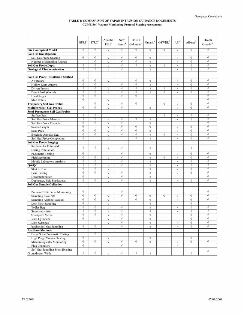
TABLE 1: COMPARISON OF VAPOR INTRUSION GUIDANCE DOCUMENTSCCME Soil Vapour Monitoring Protocol Scoping Assessment
Geosyntec Consultants
EPRI1 ITRC2 Atlantic
PIRI3
New
Jersey4
British
Columbia5 Ontario6 OSWER7 API8 Alberta9 Health
Canada10
Site Conceptual Model √ √ √ √ √ √ √ √ √ √Soil Gas Investigation Soil Gas Probe Spacing √ √ √ √ √ √ √ √ √ Number of Sampling Rounds √ √ √ √ √ √ √ √Soil Gas Probe Depth √ √ √ √ √ √ √ √ √ √Geological Characterization √ √ √ √ √ √ √ √
Soil Gas Probe Installation Method Air Rotary √ √ √ √ √ √ √ √ Hollow Stem Augers √ √ √ √ √ √ √ √ Driven Probes √ √ √ √ √ √ √ √ √ √ Direct Push (Cored) √ √ √ √ √ √ √ √ √ √ Hand Auger √ √ √ √ √ Mud Rotary √ √ √Temporary Soil Gas Probes √ √ √ √ √ √ √ √Multilevel Soil Gas Probes √ √ √ √ √ √ √ √Semi-Permanent Soil Gas Probes Surface Seal √ √ √ √ √ √ Soil Gas Probe Material √ √ √ √ √ √ √ √ √ Soil Gas Probe Diameter √ √ √ √ √ √ Screen Length √ √ √ √ √ √ √ √ Sand Pack √ √ √ √ √ √ √ √ √ Borehole Annulus Seal √ √ √ √ √ √ √ √ √ √ Soil Gas Probe Completion √ √ √ √ √ √ √Soil Gas Probe Purging Remove Air Entrained During Installation
√ √ √ √ √ √
Pneumatic Testing √ √ √ √ √ √ Field Screening √ √ √ √ √ √ √ √ √ Mobile Laboratory Analysis √ √ √ √ √ √ √QA/QC √ √ √ √ √ √ √ √ Shut In Test √ √ √ √ √ √ √ Leak Testing √ √ √ √ √ √ √ √ Decontamination √ √ √ √ √ Duplicates, field blanks, etc. √ √ √ √ √ √ √ √Soil Gas Sample Collection
Pressure Differential Monitoring √ √ √ Sampling Flow rate √ √ √ √ √ √ √ √ √ √ Sampling Applied Vacuum √ √ √ √ √ √ √ √ Low Flow Sampling √ √ √ √ Tedlar Bag √ √ √ √ √ √ √ √ Summa Canister √ √ √ √ √ √ √ √ Adsorptive Media √ √ √ √ √ √ √ Glass Cylinders √ √ √ √ √ √ Glass Syringes √ √ √ √ √ √ Passive Soil Gas Sampling √ √ √ √ √ √ √Ancillary Methods Large Scale Pneumatic Testing √ High Purge Volume Testing √ √ √ √ Meteorologically Monitoring √ √ √ √ √ √ √ √ √ Flux Chambers √ √ √ Soil Gas Sampling From Existing Groundwater Wells √ √ √ √ √ √ √
√
TR0290B 07/08/2008

TABLE 1: COMPARISON OF VAPOR INTRUSION GUIDANCE DOCUMENTSCCME Soil Vapour Monitoring Protocol Scoping Assessment
Geosyntec Consultants
Notes:
10Health Canada, 2007. Draft Guidance Manual for Environmental Site Characterization in Support of Human Health Risk Assessment,, May 28, 2007.
9Alberta Ministry of Environment, 2007. Preliminary Draft Report On Development of Tier 2 Site Specific Remediation Objectives for Soil Vapour In Alberta, July, 2007.
1EPRI, 2005. Reference Handbook for the Site-Specific Assessment of Subsurface Vapor Intrusion to Indoor Air, EPRI Document #1008492, Palo Alto, CA, March, 2005.
2Interstate Technology Regulatory Council (ITRC) 2007. Technical and Regulatory Guidance. Vapor Intrusion Pathway: A Practical Guideline. January, 2007
3Atlantic Partnership in Risk-Based Corrective Action (RBCA) Implementation (Atlantic PIRI) 2006. Atlantic Risk-Based Corrective Action for Petroleum Impacted Sites in Atlantic Canada. Guidance for Soil Vapour and Indoor Air Monitoring Assessments. July, 2006
4New Jersey Department of Environment Protection (NJDEP, 2005) NJDEP Vapor Intrusion Guidance, October 2005.
6Ontario Ministry of Environment (Ontario MOE), 2007. Draft Report. Technical Guidance Document. Soil Vapour at Contaminated Sites. Behaviour, Assessment and Monitoring. September, 2007.
5British Columbia Ministry of Environment (British Columbia MOE), 2006. Draft Technical Guidance on Contaminated Site. Soil Vapour Investigations. December, 2006.
7United States Environmental Protection Agency (US EPA), 2002. OSWER Guidance for Evaluating the Vapor Intrusion to Indoor Air Pathway from Groundwater and Soils (Subsurface Vapor Intrusion Guidance). November 29, 2002.
8American Petroleum Institute (API), 2005. Collecting and Interpreting Soil Gas Samples from the Vadose Zone: A Practical Strategy for Assessing the Subsurface-Vapor-to-Indoor-Air Migration Pathway at Petroleum Hydrocarbon Sites, Final Draft, November 2005.
TR0290B 07/08/2008
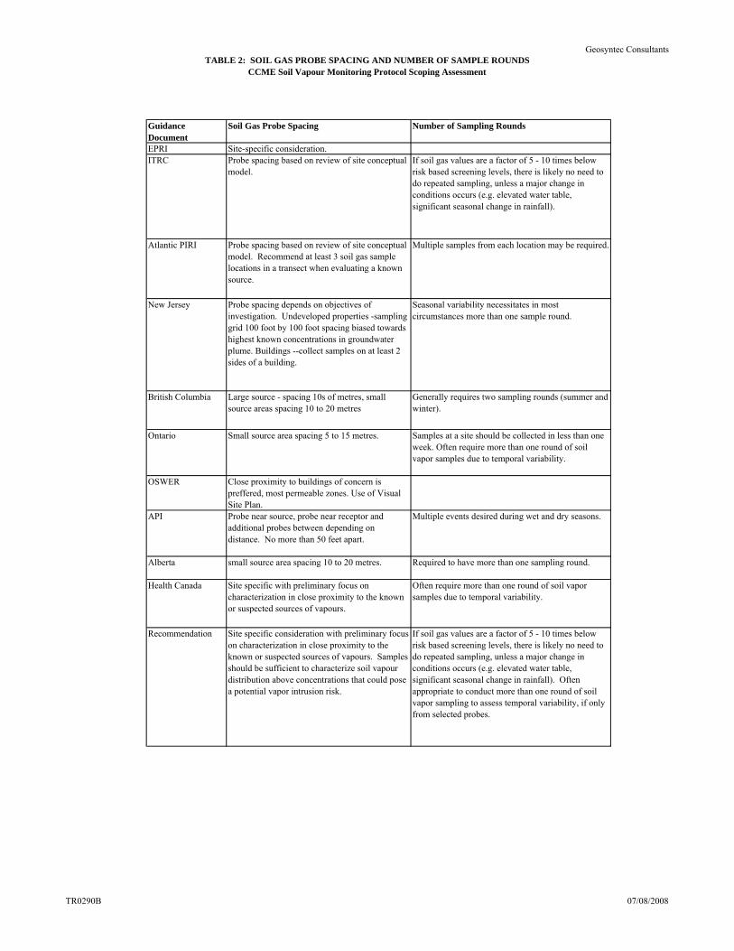
TABLE 2: SOIL GAS PROBE SPACING AND NUMBER OF SAMPLE ROUNDSCCME Soil Vapour Monitoring Protocol Scoping Assessment
Geosyntec Consultants
Guidance Document
Soil Gas Probe Spacing Number of Sampling Rounds
EPRI Site-specific consideration.ITRC Probe spacing based on review of site conceptual
model. If soil gas values are a factor of 5 - 10 times below risk based screening levels, there is likely no need to do repeated sampling, unless a major change in conditions occurs (e.g. elevated water table, significant seasonal change in rainfall).
Atlantic PIRI Probe spacing based on review of site conceptual model. Recommend at least 3 soil gas sample locations in a transect when evaluating a known source.
Multiple samples from each location may be required.
New Jersey Probe spacing depends on objectives of investigation. Undeveloped properties -sampling grid 100 foot by 100 foot spacing biased towards highest known concentrations in groundwater plume. Buildings --collect samples on at least 2 sides of a building.
Seasonal variability necessitates in most circumstances more than one sample round.
British Columbia Large source - spacing 10s of metres, small source areas spacing 10 to 20 metres
Generally requires two sampling rounds (summer and winter).
Ontario Small source area spacing 5 to 15 metres. Samples at a site should be collected in less than one week. Often require more than one round of soil vapor samples due to temporal variability.
OSWER Close proximity to buildings of concern is preffered, most permeable zones. Use of Visual Site Plan.
API Probe near source, probe near receptor and additional probes between depending on distance. No more than 50 feet apart.
Multiple events desired during wet and dry seasons.
Alberta small source area spacing 10 to 20 metres. Required to have more than one sampling round.
Health Canada Site specific with preliminary focus on characterization in close proximity to the known or suspected sources of vapours.
Often require more than one round of soil vapor samples due to temporal variability.
Recommendation Site specific consideration with preliminary focus on characterization in close proximity to the known or suspected sources of vapours. Samples should be sufficient to characterize soil vapour distribution above concentrations that could pose a potential vapor intrusion risk.
If soil gas values are a factor of 5 - 10 times below risk based screening levels, there is likely no need to do repeated sampling, unless a major change in conditions occurs (e.g. elevated water table, significant seasonal change in rainfall). Often appropriate to conduct more than one round of soil vapor sampling to assess temporal variability, if only from selected probes.
TR0290B 07/08/2008

TABLE 3: SOIL GAS PROBE DEPTHCCME Soil Vapour Monitoring Protocol Scoping Assessment
Geosyntec Consultants
Guidance Document
Maximum depth Minimum depth Comments
EPRI 5 ft. bgs Soil gas probes installed adjacent to a building should be a few feet below depth of foundation.
ITRC Install probe just above source or 10 feet below receptor. Install no deeper than the capillary fringe.
Generally deeper than 3 to 5 ft. bgs. Recommend mulitple sample depths (generally 3) to define vertical trends.
Atlantic PIRI 5 metres or 0.5 to 1 metres above the water table.
1 m. bgs Screened interval should be greater than halfway from bottom of building foundation to source or the water table. Multilevel probes should be installed to 3 depths intervals (near source, midpoint, near receptor).
New Jersey 2 to 5 feet below slab. 5 ft. bgs, 1 foot above capillary fringe. If groundwater is shallower than 5 feet an alternate method must be used. Recommend soil gas probes 8 - 10 ft. bgs for undevoped parcels of land.
British Columbia 0.5 to 1 metre above water table and above capillary fringe.
minimum 1 metre below ground surface and more than halfway between receptor and source.
Prefer depth that is more than halfway in the vertical direction between receptor and source.
Ontario Should be installed 0.5 to 1 metre above the water table. Maximum of 10 metres below ground surface.
Minimum depth equal to half-way between lowest receptor (building foundation) and contamination source, futher constrained to be a minimum of 1 m. bgs.
Require contaminant source at least 1.5 m. bgs to get vertical resolution when installing multilevel probes.
OSWER recommend greater than 5 ft. bgs, unless immediately below building foundation.
API Dependant on site conditions and conceptual model.
3 ft. bgs. Collect immediately above vapor source, or laterally mid way between source and building, or adjacent to building foundation or basement, or immediately below building foundation or basement, or within footprint of future building.
Alberta 0.5 to 1 metre above water table or 5 m. bgs.
Recommend minimum depth equal to half-way between lowest part of building foundation and source.
Require contaminant source at least 1.5 m. bgs to get vertical resolution when installing multilevel probes.
Health Canada Above water table and capillary fringe
Recommend minimum depth equal to half-way between lowest part of building foundation and source.
Recommendation Install probe just above source or 10 feet below receptor. Install no deeper than the capillary fringe.
5 ft. bgs or at least a few feet below the building foundation, whichever is deeper.
Multiple probes can be installed to define vertical trends if required. Vertical profiles are advisable for petroleum hydrocarbon sites, at least in selected areas. Vertical profiles are also advisable where there are significant stratigraphic layers of fine and coarse-textured materials in the unsaturated zone.
Notes:ft. bgs - feet below ground surfacesm. bgs - metres below ground surfaces
TR0290B 07/08/2008
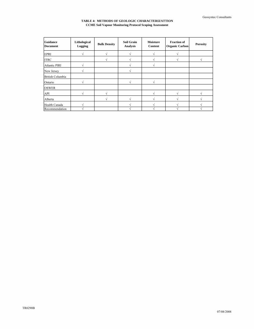
TABLE 4: METHODS OF GEOLOGIC CHARACTERIZATTIONCCME Soil Vapour Monitoring Protocol Scoping Assessment
Geosyntec Consultants
Guidance Document
Lithological Logging
Bulk DensitySoil Grain Analysis
Moisture Content
Fraction of Organic Carbon
Porosity
EPRI √ √ √ √ √
ITRC √ √ √ √ √
Atlantic PIRI √ √ √
New Jersey √ √
British Columbia
Ontario √ √ √
OSWER
API √ √ √ √ √
Alberta √ √ √ √ √
Health Canada √ √ √ √ √Recommendation √ √ √ √ √
TR0290B07/08/2008
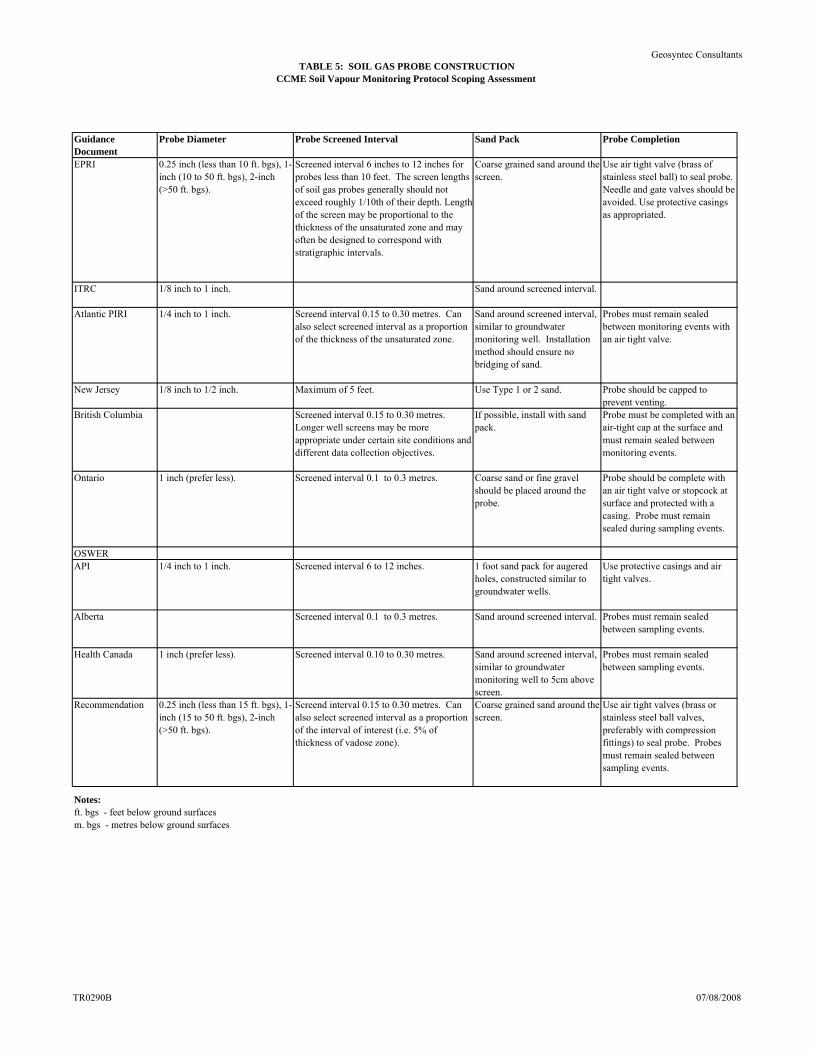
TABLE 5: SOIL GAS PROBE CONSTRUCTIONCCME Soil Vapour Monitoring Protocol Scoping Assessment
Geosyntec Consultants
Guidance Document
Probe Diameter Probe Screened Interval Sand Pack Probe Completion
EPRI 0.25 inch (less than 10 ft. bgs), 1-inch (10 to 50 ft. bgs), 2-inch (>50 ft. bgs).
Screened interval 6 inches to 12 inches for probes less than 10 feet. The screen lengths of soil gas probes generally should not exceed roughly 1/10th of their depth. Length of the screen may be proportional to the thickness of the unsaturated zone and may often be designed to correspond with stratigraphic intervals.
Coarse grained sand around the screen.
Use air tight valve (brass of stainless steel ball) to seal probe. Needle and gate valves should be avoided. Use protective casings as appropriated.
ITRC 1/8 inch to 1 inch. Sand around screened interval.
Atlantic PIRI 1/4 inch to 1 inch. Screend interval 0.15 to 0.30 metres. Can also select screened interval as a proportion of the thickness of the unsaturated zone.
Sand around screened interval, similar to groundwater monitoring well. Installation method should ensure no bridging of sand.
Probes must remain sealed between monitoring events with an air tight valve.
New Jersey 1/8 inch to 1/2 inch. Maximum of 5 feet. Use Type 1 or 2 sand. Probe should be capped to prevent venting.
British Columbia Screened interval 0.15 to 0.30 metres. Longer well screens may be more appropriate under certain site conditions and different data collection objectives.
If possible, install with sand pack.
Probe must be completed with an air-tight cap at the surface and must remain sealed between monitoring events.
Ontario 1 inch (prefer less). Screened interval 0.1 to 0.3 metres. Coarse sand or fine gravel should be placed around the probe.
Probe should be complete with an air tight valve or stopcock at surface and protected with a casing. Probe must remain sealed during sampling events.
OSWERAPI 1/4 inch to 1 inch. Screened interval 6 to 12 inches. 1 foot sand pack for augered
holes, constructed similar to groundwater wells.
Use protective casings and air tight valves.
Alberta Screened interval 0.1 to 0.3 metres. Sand around screened interval. Probes must remain sealed between sampling events.
Health Canada 1 inch (prefer less). Screened interval 0.10 to 0.30 metres. Sand around screened interval, similar to groundwater monitoring well to 5cm above screen.
Probes must remain sealed between sampling events.
Recommendation 0.25 inch (less than 15 ft. bgs), 1-inch (15 to 50 ft. bgs), 2-inch (>50 ft. bgs).
Screend interval 0.15 to 0.30 metres. Can also select screened interval as a proportion of the interval of interest (i.e. 5% of thickness of vadose zone).
Coarse grained sand around the screen.
Use air tight valves (brass or stainless steel ball valves, preferably with compression fittings) to seal probe. Probes must remain sealed between sampling events.
Notes:ft. bgs - feet below ground surfacesm. bgs - metres below ground surfaces
TR0290B 07/08/2008
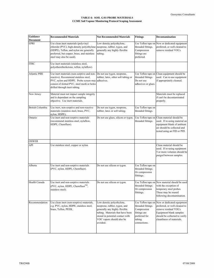
TABLE 6: SOIL GAS PROBE MATERIALSCCME Soil Vapour Monitoring Protocol Scoping Assessment
Geosyntec Consultants
Guidance Document
Recommended Materials Not Recommended Materials Fittings Decontamination
EPRI Use clean inert materials (polyvinyl chloride (PVC), high-density polyethylene (HDPE), Teflon, and nylon are generally preferred, but copper, brass, and stainless steel may also be used).
Low density polyethylene, neoprene, rubber, tygon, and generally any highly flexible tubing.
Use Teflon tape on threaded fittings. Compression fittings are preferred.
New or dedicated equipment preferred, or well cleaned to remove residual VOCs.
ITRC Use inert materials (stainless steel, polyetheretherketone, teflon, nylaflow).
Atlantic PIRI Use inert materials (non-sorptive and non-reactive). Recommend stainless steel, PVC, nylon and HDPE. Probe screen may consist of slotted PVC, steel mesh or holes drilled through inert tubing.
Do not use tygon, neoprene, rubber, latex, other soft tubing or adhesives.
Use Teflon tape on threaded fittings. Do not use adhesives or glues.
Clean equipment should be used. Can re-use equipment if appropriately cleaned.
New Jersey Material must not impact sample integrity and is dependant on the sampling objective. Use inert materials.
Materials must be replaced if can't be decontaminated properly.
British Columbia Use inert, non-sorptive and non-reactive materials (stainless steel, brass, PVC, nylon, HDPE).
Do not use tygon, neoprene, rubber, latex or soft tubing.
Use Teflon tape on threaded fittings.
Ontario Use inert and non-sorptive materials (recommend stainless steel, nylaflow, HDPE, Chemfluor).
Do not use glues, silicon or tygon. Use Teflon tape on threaded fittings.
Clean material should be used. If re-using material an equipment blank of ambient air should be collected and tested using an FID or PID.
OSWER
API Use stainless steel, copper or nylon. Clean material should be used. If re-using equipment 5 or more volumes should be purged between samples.
Alberta Use inert and non-sorptive materials (PVC, nylon, HDPE, Chemfluor).
Do not use silicon or tygon. Use Teflon tape on threaded fittings. Or compression fitttings.
Health Canada Use inert and non-sorptive materials
(PVC, nylon, HDPE, ChemfluorTM, stainless steel).
Do not use silicon or tygon. Use Teflon tape on threaded fittings. Or compression fitttings.
New material should be used with the exception of temporary steel probes. These may be reused following decontamination.
Recommendation Use clean inert (non-sorptive) materials, e.g. PVC, nylon, HDPE, stainless steel, brass, Teflon, PEEK.
Low density polyethylene, neoprene, rubber, tygon, and generally any highly flexible tubing. Materials that have been stored in potential contact with VOC vapors should also be avoided.
Use Teflon tape on threaded fittings. Compression fittings are preferred for tubing connections.
New or dedicated equipment preferred, or well cleaned to remove residual VOCs. Equipment blank samples should be collected to verify cleanliness of materials.
TR0290B 07/08/2008
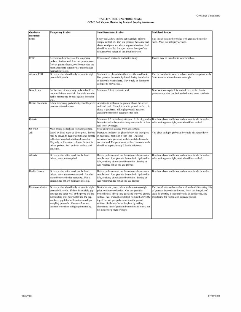
TABLE 7: SOIL GAS PROBE SEALSCCME Soil Vapour Monitoring Protocol Scoping Assessment
Geosyntec Consultants
Guidance Document
Temporary Probes Semi-Permanent Probes Multilevel Probes
EPRI Slurry seal, allow seals to set overnight prior to sample collection. Can use granular bentonite seal above sand pack and slurry to ground surface. Seal should be installed from just above the top of the soil gas probe screen to the ground surface.
Can install in same boreholes with granular bentonite seals. Must test integrity of seals.
ITRC Recommend surface seal for temporary probes. Surface seal does not prevent cross flow at greater depths, so driven probes are most applicable in relatively uniform high permeability soils.
Recommend bentonite and water slurry. Probes may be installed in same borehole.
Atlantic PIRI Driven probes should only be used in high permeability soils.
Seal must be placed directly above the sand back. Use granular bentonite hydrated during installation or bentonite water slurry. Never rely on formation collapse to provide seal.
Can be installed in same borehole, verify competent seals. Seals must be allowed to set overnight.
New Jersey Surface seal of temporary probes should be made with inert material. Borehole annulus seal is maintained by rods against borehole wall.
Minimum 2 foot bentonite seal. New location required for each driven probe. Semi-permanent probes can be installed in the same borehole.
British Columbia Allow temporary probes but generally prefer permanent installations.
A bentonite seal must be present above the screen and sand pack. Complete seal to ground surface. A slurry is preferred, although properly hydrated granular bentonite is acceptable for seal.
Ontario Minimum 0.3 metre bentonite seal. Lifts of granular bentonite and or bentonite slurry acceptable. Allow seal to set overnight.
Borehole above and below each screen should be sealed. After waiting overnight, seals should be checked.
OSWER Must ensure no leakage from atmosphere. Must ensure no leakage from atmosphere.
API Install by hand auger or direct push. Probes may be driven to deeper depths after sample collection to collect additional samples. May rely on formation collapse for seal in driven probes. Seal probe at surface with bentonite.
Bentonite seal must be placed above the sand pack in multilevel probes in 6 inch lifts. On some occasions sand pack and seal are installed as rods are removed. For permanent probes, bentonite seals should be approximately 3 feet in thickness.
Can place multiple probes in borehole of augered holes.
Alberta Driven probes often used, can be hand driven, tracer test required.
Driven probes cannot use formation collapse as an annular seal. Use granular bentonite in hydrated in lifts, or slurry of powdered bentonite. Testing of seal required for all soil gas probes.
Borehole above and below each screen should be sealed. After waiting overnight, seals should be checked.
Health Canada Driven probes often used, can be hand driven, tracer test recommended. Annulus should be sealed with bentonite. Use is discouraged for low permeability soils.
Driven probes cannot use formation collapse as an annular seal. Use granular bentonite in hydrated in lifts, or slurry of powdered bentonite. Testing of seal recommended for all soil gas probes.
Borehole above and below each screen should be sealed.
Recommendation Driven probes should only be used in high-permeability soils. If there is a visible gap between the outer wall of the probe and the surrounding soil, pour water into the gap, and keep gap filled with water as soil gas sampling proceeds. Measure flow and vacuum to confirm soil gas permeability.
Bentonite slurry seal, allow seals to set overnight prior to sample collection. Can use granular bentonite seal above sand pack and slurry to ground surface. Seal should be installed from just above the top of the soil gas probe screen to the ground surface. Seals may be set in-place by adding alternating lifts of granular bentonite and water, but not bentonite pellets or chips.
Can install in same boreholes with seals of alternating lifts of granular bentonite and water. Must test integrity of seals by exerting a vacuum briefly on each probe, and monitoring for response in adjacent probes.
TR0290B 07/08/2008
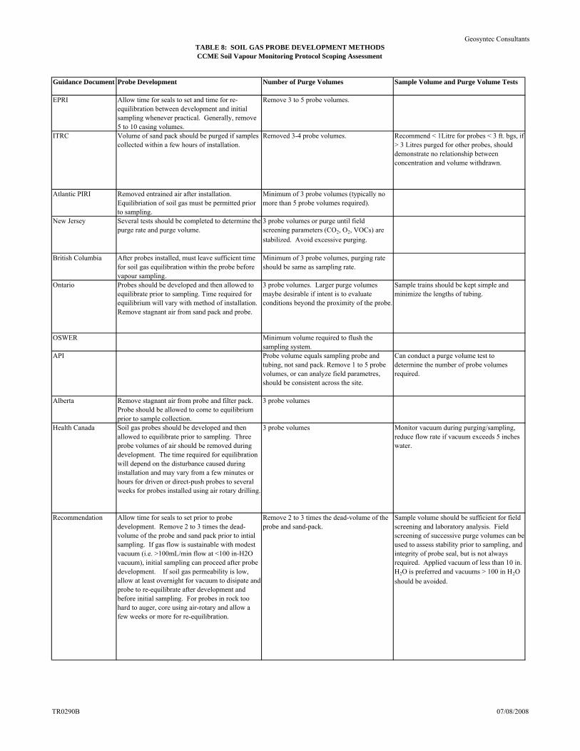
TABLE 8: SOIL GAS PROBE DEVELOPMENT METHODSCCME Soil Vapour Monitoring Protocol Scoping Assessment
Geosyntec Consultants
Guidance Document Probe Development Number of Purge Volumes Sample Volume and Purge Volume Tests
EPRI Allow time for seals to set and time for re-equilibration between development and initial sampling whenever practical. Generally, remove 5 to 10 casing volumes.
Remove 3 to 5 probe volumes.
ITRC Volume of sand pack should be purged if samples collected within a few hours of installation.
Removed 3-4 probe volumes. Recommend < 1Litre for probes < 3 ft. bgs, if > 3 Litres purged for other probes, should demonstrate no relationship between concentration and volume withdrawn.
Atlantic PIRI Removed entrained air after installation. Equilibriation of soil gas must be permitted prior to sampling.
Minimum of 3 probe volumes (typically no more than 5 probe volumes required).
New Jersey Several tests should be completed to determine the purge rate and purge volume.
3 probe volumes or purge until field screening parameters (CO2, O2, VOCs) are
stabilized. Avoid excessive purging.
British Columbia After probes installed, must leave sufficient time for soil gas equilibration within the probe before vapour sampling.
Minimum of 3 probe volumes, purging rate should be same as sampling rate.
Ontario Probes should be developed and then allowed to equilibrate prior to sampling. Time required for equilibrium will vary with method of installation. Remove stagnant air from sand pack and probe.
3 probe volumes. Larger purge volumes maybe desirable if intent is to evaluate conditions beyond the proximity of the probe.
Sample trains should be kept simple and minimize the lengths of tubing.
OSWER Minimum volume required to flush the sampling system.
API Probe volume equals sampling probe and tubing, not sand pack. Remove 1 to 5 probe volumes, or can analyze field parametres, should be consistent across the site.
Can conduct a purge volume test to determine the number of probe volumes required.
Alberta Remove stagnant air from probe and filter pack. Probe should be allowed to come to equilibrium prior to sample collection.
3 probe volumes
Health Canada Soil gas probes should be developed and then allowed to equilibrate prior to sampling. Three probe volumes of air should be removed during development. The time required for equilibration will depend on the disturbance caused during installation and may vary from a few minutes or hours for driven or direct-push probes to several weeks for probes installed using air rotary drilling.
3 probe volumes Monitor vacuum during purging/sampling, reduce flow rate if vacuum exceeds 5 inches water.
Recommendation Allow time for seals to set prior to probe development. Remove 2 to 3 times the dead-volume of the probe and sand pack prior to intial sampling. If gas flow is sustainable with modest vacuum (i.e. >100mL/min flow at <100 in-H2O vacuum), initial sampling can proceed after probe development. If soil gas permeability is low, allow at least overnight for vacuum to disipate and probe to re-equilibrate after development and before initial sampling. For probes in rock too hard to auger, core using air-rotary and allow a few weeks or more for re-equilibration.
Remove 2 to 3 times the dead-volume of the probe and sand-pack.
Sample volume should be sufficient for field screening and laboratory analysis. Field screening of successive purge volumes can be used to assess stability prior to sampling, and integrity of probe seal, but is not always required. Applied vacuum of less than 10 in. H2O is preferred and vacuums > 100 in H2O
should be avoided.
TR0290B 07/08/2008
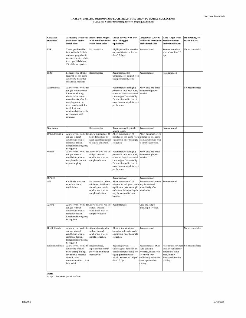
TABLE 9: DRILLING METHODS AND EQUILIBRIUM TIME PRIOR TO SAMPLE COLLECTIONCCME Soil Vapour Monitoring Protocol Scoping Assessment
Geosyntec Consultants
Guidance Document
Air Rotary With Semi Permanent Probe Installation
Hollow Stem Augers With Semi Permanent Probe Installation
Driven Probes With Post-Run Tubing (or equivalent)
Direct Push (Cored) With Semi Permanent Probe Installation
Hand Auger With Semi Permanent Probe Installation
Mud Rotary, or Water Rotary
EPRI Tracer gas should be injected in the drill air and then purged until the concentration of the tracer gas falls below 1% of the air injected.
Recommended Highly permeable materials only and should be deeper than 5 ft. bgs.
Recommended Recommended for probes less than 5 ft. bgs.
Not recommended
ITRC Longer period of time required for soil gas to equilibrate than other installation methods.
Recommended Recommended for temporary soil gas probes in high permeability soils.
Recommended Recommended
Atlantic PIRI Allow several weeks for soil gas to equilibriate. Repeat monitoring should be conducted several weeks after first sampling event. A tracer may be added to the drill air and monitored during probe development until removed.
Recommended for highly permeable soils only. Only use when there is advanced knowledge of permeability. Do not allow collection of more than one depth interval per location.
Allow only one depth discrete sample per location.
Not recommended
New Jersey Recommended Recommended for single sample round.
Recommended Recommended
British Columbia Allow several weeks for soil gas to reach equilibrium prior to sample collection. Repeat monitoring may be required.
Allow minimum of 48 hours for soil gas to reach equilibrium prior to sample collection.
Allow minimum of 30 minutes for soil gas to reach equilibrium prior to sample collection.
Allow minimum of 30 minutes for soil gas to reach equilibrium prior to sample collection.
Ontario Allow several weeks for soil gas to reach equilibrium prior to sample collection and repeat sampling.
Allow a day or two for soil gas to reach equilibrium prior to sample collection.
Recommended for highly permeable soils only. Only use when there is advanced knowledge of permeability. Do not allow collection of more than one depth interval per location.
Allow only one depth discrete sample per location.
OSWER Recommended Recommended
API Could take weeks or months to reach equillibrium
Recommended. Allow minimum of 48 hours for soil gas to reach equilibrium prior to sample collection.
Allow minimum of 20 minutes for soil gas to reach equilibrium prior to sample collection. Multiple depths may be sampled in same location.
Recommended, probes may be sampled immediately after installation.
Recommended
Alberta Allow several weeks for soil gas to reach equilibrium prior to sample collection. Repeat monitoring may be required.
Allow a day or two for soil gas to reach equilibrium prior to sample collection.
Recommended Only one sample interval per location.
Health Canada Allow several weeks for soil gas to reach equilibrium prior to sample collection. Repeat monitoring may be required.
Allow a few days for soil gas to reach equilibrium prior to sample collection.
Allow a few minutes or hours for soil gas to reach equilibrium prior to sample collection.
Recommended Not recommended
Recommendation Allow several weeks to equilibrate or inject tracer during drilling and remove entrained air until tracer concentration is < 1% ofinjected air.
Recommended, especially for deeper probes or multi-level installations.
Requires previous knowledge of permeability and recommended only for highly permeable soils. Should be installed deeper than 5 ft bgs.
Recommended. Dual-Tube coring is preferred, unless soils are known to be sufficiently cohesive to stand open without caving.
Recommended where soils are sufficiently cohesive to stand open, and not overconsolidated or cobbley.
Not recommended
Notes:ft. bgs - feet below ground surfaces
TR0290B 07/08/2008
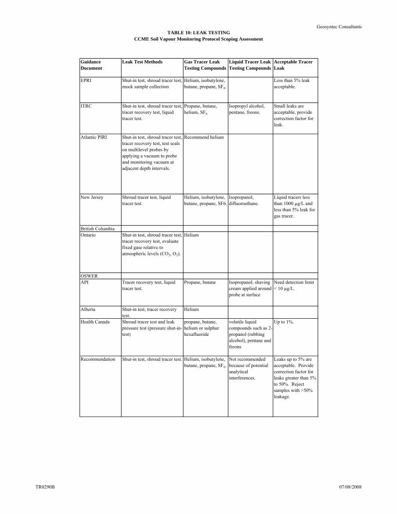
TABLE 10: LEAK TESTINGCCME Soil Vapour Monitoring Protocol Scoping Assessment
Geosyntec Consultants
Guidance Document
Leak Test Methods Gas Tracer Leak Testing Compounds
Liquid Tracer Leak Testing Compounds
Acceptable Tracer Leak
EPRI Shut-in test, shroud tracer test, mock sample collection
Helium, isobutylene, butane, propane, SF6.
Less than 5% leak acceptable.
ITRC Shut-in test, shroud tracer test, tracer recovery test, liquid tracer test.
Propane, butane, helium, SF6.
Isopropyl alcohol, pentane, freons.
Small leaks are acceptable, provide correction factor for leak.
Atlantic PIRI Shut-in test, shroud tracer test, tracer recovery test, test seals on multilevel probes by applying a vacuum to probe and monitoring vacuum at adjacent depth intervals.
Recommend helium
New Jersey Shroud tracer test, liquid tracer test.
Helium, isobutylene, butane, propane, SF6.
Isopropanol, difluoroethane.
Liquid tracers less than 1000 µg/L and less than 5% leak for gas tracer.
British ColumbiaOntario Shut-in test, shroud tracer test,
tracer recovery test, evaluate fixed gase relative to atmospheric levels (CO2, O2).
Helium
OSWERAPI Tracer recovery test, liquid
tracer test.Propane, butane Isopropanol, shaving
cream applied around probe at surface
Need detection limit < 10 µg/L.
Alberta Shut-in test, tracer recovery test.
Helium
Health Canada Shroud tracer test and leak pressure test (pressure shut-in-test)
propane, butane, helium or sulphur hexafluoride
volatile liquid compounds such as 2-propanol (rubbing alcohol), pentane and freons
Up to 1%.
Recommendation Shut-in test, shroud tracer test. Helium, isobutylene, butane, propane, SF6.
Not recommended because of potential analytical interferences.
Leaks up to 5% are acceptable. Provide correction factor for leaks greater than 5% to 50%. Reject samples with >50% leakage.
TR0290B 07/08/2008
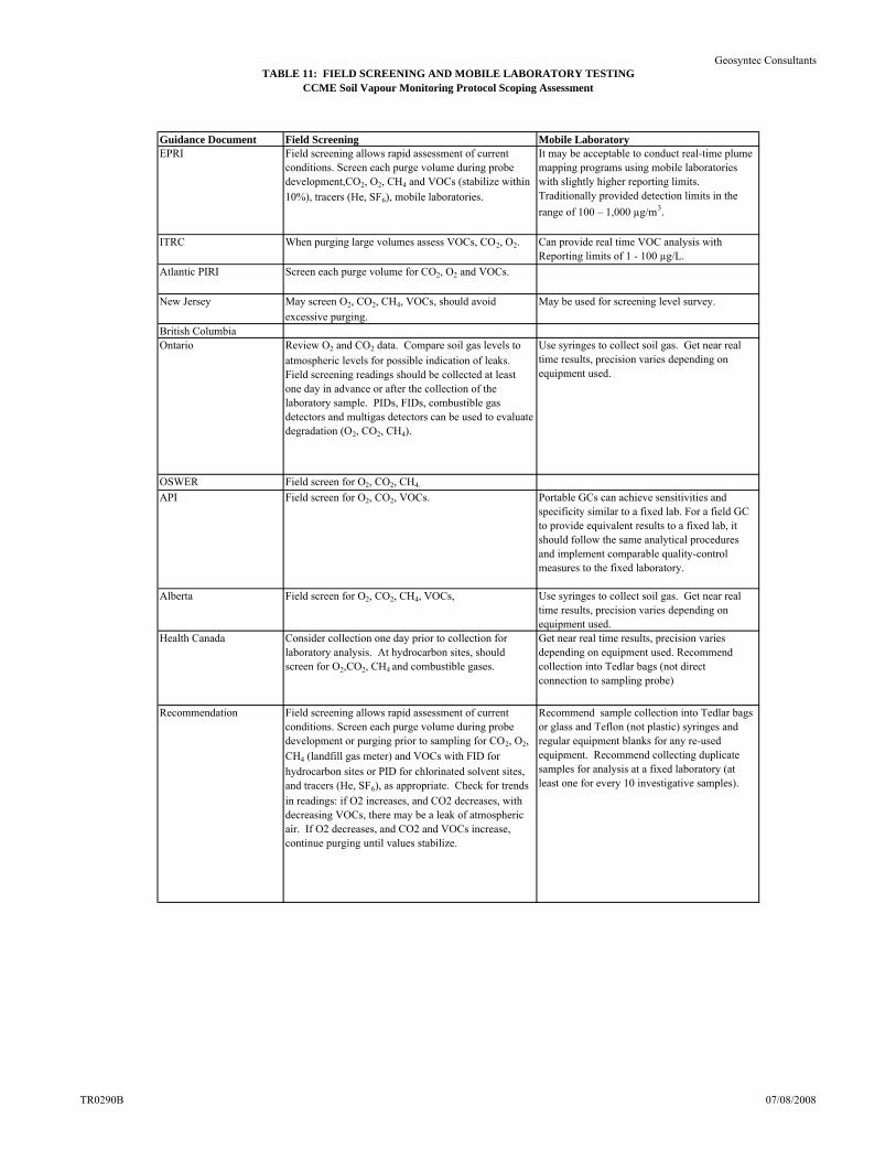
TABLE 11: FIELD SCREENING AND MOBILE LABORATORY TESTINGCCME Soil Vapour Monitoring Protocol Scoping Assessment
Geosyntec Consultants
Guidance Document Field Screening Mobile LaboratoryEPRI Field screening allows rapid assessment of current
conditions. Screen each purge volume during probe development,CO2, O2, CH4 and VOCs (stabilize within 10%), tracers (He, SF6), mobile laboratories.
It may be acceptable to conduct real-time plume mapping programs using mobile laboratories with slightly higher reporting limits. Traditionally provided detection limits in the
range of 100 – 1,000 µg/m3.
ITRC When purging large volumes assess VOCs, CO2, O2. Can provide real time VOC analysis with Reporting limits of 1 - 100 µg/L.
Atlantic PIRI Screen each purge volume for CO2, O2 and VOCs.
New Jersey May screen O2, CO2, CH4, VOCs, should avoid excessive purging.
May be used for screening level survey.
British ColumbiaOntario Review O2 and CO2 data. Compare soil gas levels to
atmospheric levels for possible indication of leaks. Field screening readings should be collected at least one day in advance or after the collection of the laboratory sample. PIDs, FIDs, combustible gas detectors and multigas detectors can be used to evaluate degradation (O2, CO2, CH4).
Use syringes to collect soil gas. Get near real time results, precision varies depending on equipment used.
OSWER Field screen for O2, CO2, CH4.
API Field screen for O2, CO2, VOCs. Portable GCs can achieve sensitivities and specificity similar to a fixed lab. For a field GC to provide equivalent results to a fixed lab, it should follow the same analytical procedures and implement comparable quality-control measures to the fixed laboratory.
Alberta Field screen for O2, CO2, CH4, VOCs, Use syringes to collect soil gas. Get near real time results, precision varies depending on equipment used.
Health Canada Consider collection one day prior to collection for laboratory analysis. At hydrocarbon sites, should screen for O2,CO2, CH4 and combustible gases.
Get near real time results, precision varies depending on equipment used. Recommend collection into Tedlar bags (not direct connection to sampling probe)
Recommendation Field screening allows rapid assessment of current conditions. Screen each purge volume during probe development or purging prior to sampling for CO2, O2, CH4 (landfill gas meter) and VOCs with FID for hydrocarbon sites or PID for chlorinated solvent sites, and tracers (He, SF6), as appropriate. Check for trends in readings: if O2 increases, and CO2 decreases, with decreasing VOCs, there may be a leak of atmospheric air. If O2 decreases, and CO2 and VOCs increase, continue purging until values stabilize.
Recommend sample collection into Tedlar bags or glass and Teflon (not plastic) syringes and regular equipment blanks for any re-used equipment. Recommend collecting duplicate samples for analysis at a fixed laboratory (at least one for every 10 investigative samples).
TR0290B 07/08/2008
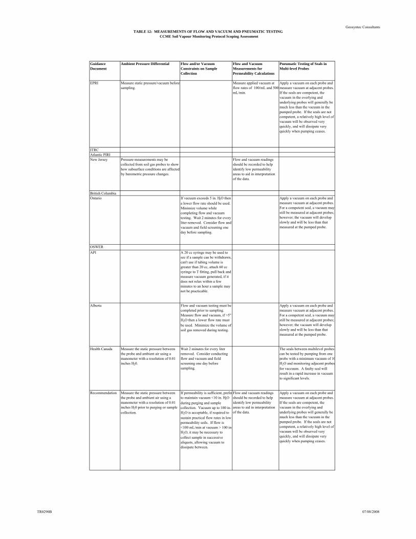
TABLE 12: MEASUREMENTS OF FLOW AND VACUUM AND PNEUMATIC TESTINGCCME Soil Vapour Monitoring Protocol Scoping Assessment
Geosyntec Consultants
Guidance Document
Ambient Pressure Differential Flow and/or Vacuum Constraints on Sample Collection
Flow and Vacuum Measurements for Permeability Calculations
Pneumatic Testing of Seals in Multi-level Probes
EPRI Measure static pressure/vacuum before sampling.
Measure applied vacuum at flow rates of 100/mL and 500 mL/min.
Apply a vacuum on each probe and measure vacuum at adjacent probes. If the seals are competent, the vacuum in the overlying and underlying probes will generally be much less than the vacuum in the pumped probe. If the seals are not competent, a relatively high level of vacuum will be observed very quickly, and will dissipate very quickly when pumping ceases.
ITRCAtlantic PIRINew Jersey Pressure measurements may be
collected from soil gas probes to show how subsurface conditions are affected by barometric pressure changes.
Flow and vacuum readings should be recorded to help identify low permeability areas to aid in interpretation of the data.
British ColumbiaOntario If vacuum exceeds 5 in. H2O then
a lower flow rate should be used. Minimize volume while completing flow and vacuum testing. Wait 2 minutes for every liter removed. Consider flow and vacuum and field screening one day before sampling.
Apply a vacuum on each probe and measure vacuum at adjacent probes. For a competent seal, a vacuum may still be measured at adjacent probes; however; the vacuum will develop slowly and will be less than that measured at the pumped probe.
OSWER
API A 20 cc syringe may be used to see if a sample can be withdrawn, can't use if tubing volume is greater than 20 cc, attach 60 cc syringe to T fitting, pull back and measure vacuum generated, if it does not relax within a few minutes to an hour a sample may not be practicable.
Alberta Flow and vacuum testing must be completed prior to sampling. Measure flow and vacuum, if >5" H2O then a lower flow rate must
be used. Minimize the volume of soil gas removed during testing.
Apply a vacuum on each probe and measure vacuum at adjacent probes. For a competent seal, a vacuum may still be measured at adjacent probes; however; the vacuum will develop slowly and will be less than that measured at the pumped probe.
Health Canada Measure the static pressure between the probe and ambient air using a manometer with a resolution of 0.01 inches H20.
Wait 2 minutes for every liter removed. Consider conducting flow and vacuum and field screening one day before sampling.
The seals between multilevel probes can be tested by pumping from one probe with a minimum vacuum of 10H2O and monitoring adjacent probes
for vaccuum. A faulty seal will result in a rapid increase in vacuum to significant levels.
Recommendation Measure the static pressure between the probe and ambient air using a manometer with a resolution of 0.01 inches H20 prior to purging or sample
collection.
If permeability is sufficient, preferto maintain vacuum <10 in. H2O
during purging and sample collection. Vacuum up to 100 in-H2O is acceptable, if required to
sustain practical flow rates in low permeability soils. If flow is <100 mL/min at vacuum > 100 in-H2O, it may be necessary to
collect sample in successive aliquots, allowing vacuum to dissipate between.
Flow and vacuum readings should be recorded to help identify low permeability areas to aid in interpretation of the data.
Apply a vacuum on each probe and measure vacuum at adjacent probes. If the seals are competent, the vacuum in the overlying and underlying probes will generally be much less than the vacuum in the pumped probe. If the seals are not competent, a relatively high level of vacuum will be observed very quickly, and will dissipate very quickly when pumping ceases.
TR0290B 07/08/2008
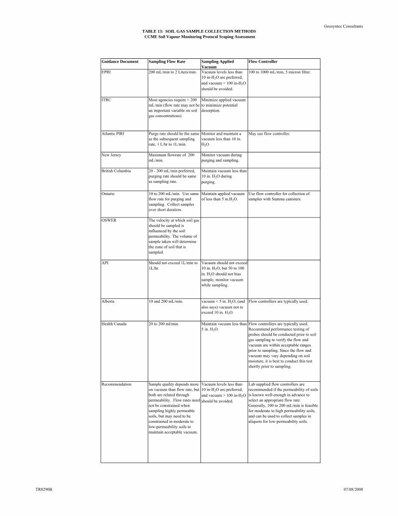
TABLE 13: SOIL GAS SAMPLE COLLECTION METHODSCCME Soil Vapour Monitoring Protocol Scoping Assessment
Geosyntec Consultants
Guidance Document Sampling Flow Rate Sampling Applied Vacuum
Flow Controller
EPRI 200 mL/min to 2 Liters/min. Vacuum levels less than 10 in-H2O are preferred, and vacuum > 100 in-H2O should be avoided.
100 to 1000 mL/min, 5 micron filter.
ITRC Most agencies require < 200 mL/min (flow rate may not be an important variable on soil gas concentrations).
Minimize applied vacuum to minimize potential desorption.
Atlantic PIRI Purge rate should be the same as the subsequent sampling rate, 1 L/hr to 1L/min.
Monitor and maintain a vacuum less than 10 in. H2O.
May use flow controller.
New Jersey Maximum flowrate of 200 mL/min.
Monitor vacuum during purging and sampling.
British Columbia 20 - 200 mL/min preferred, purging rate should be same as sampling rate.
Maintain vacuum less than 10 in. H2O during purging.
Ontario 10 to 200 mL/min. Use same flow rate for purging and sampling. Collect samples over short duration.
Maintain applied vacuum of less than 5 in.H2O.
Use flow controller for collection of samples with Summa canisters.
OSWER The velocity at which soil gas should be sampled is influenced by the soil permeability. The volume of sample taken will determine the zone of soil that is sampled.
API Should not exceed 1L/min to 1L/hr.
Vacuum should not exceed 10 in. H2O, but 50 to 100 in. H2O should not bias sample, monitor vacuum while sampling.
Alberta 10 and 200 mL/min. vacuum < 5 in. H2O, (and also says) vacuum not to exceed 10 in. H2O.
Flow controllers are typically used.
Health Canada 20 to 200 ml/min. Maintain vacuum less than 5 in. H2O.
Flow controllers are typically used. Recommend performance testing of probes should be conducted prior to soil gas sampling to verify the flow and vacuum are within acceptable ranges prior to sampling. Since the flow and vacuum may vary depending on soil moisture, it is best to conduct this test shortly prior to sampling.
Recommendation Sample quality depends more on vacuum than flow rate, but both are related through permeability. Flow rates need not be constrained when sampling highly permeable soils, but may need to be constrained in moderate to low-permeability soils to maintain acceptable vacuum.
Vacuum levels less than 10 in-H2O are preferred, and vacuum > 100 in-H2O should be avoided.
Lab supplied flow controllers are recommended if the permeability of soils is known well-enough in advance to select an appropriate flow rate. Generally, 100 to 200 mL/min is feasible for moderate to high permeability soils, and can be used to collect samples in aliquots for low-permeability soils.
TR0290B 07/08/2008
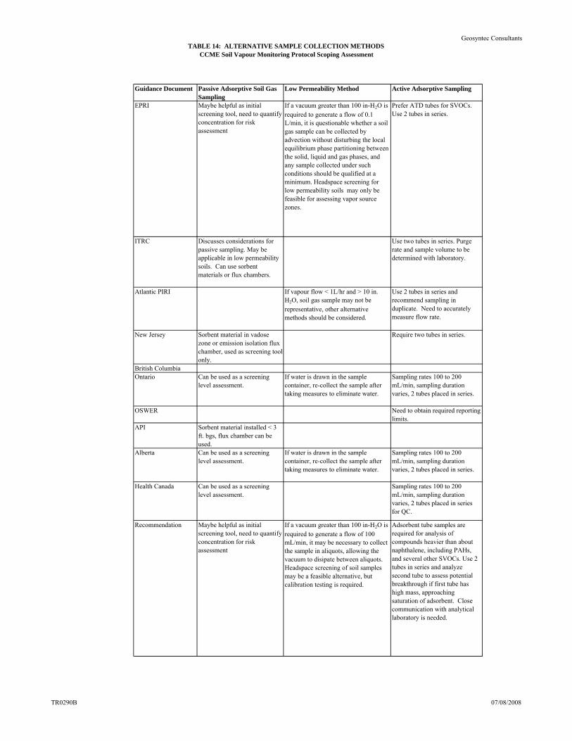
TABLE 14: ALTERNATIVE SAMPLE COLLECTION METHODSCCME Soil Vapour Monitoring Protocol Scoping Assessment
Geosyntec Consultants
Guidance Document Passive Adsorptive Soil Gas Sampling
Low Permeability Method Active Adsorptive Sampling
EPRI Maybe helpful as initial screening tool, need to quantify concentration for risk assessment
If a vacuum greater than 100 in-H2O is required to generate a flow of 0.1 L/min, it is questionable whether a soil gas sample can be collected by advection without disturbing the local equilibrium phase partitioning between the solid, liquid and gas phases, and any sample collected under such conditions should be qualified at a minimum. Headspace screening for low permeability soils may only be feasible for assessing vapor source zones.
Prefer ATD tubes for SVOCs. Use 2 tubes in series.
ITRC Discusses considerations for passive sampling. May be applicable in low permeability soils. Can use sorbent materials or flux chambers.
Use two tubes in series. Purge rate and sample volume to be determined with laboratory.
Atlantic PIRI If vapour flow < 1L/hr and > 10 in. H2O, soil gas sample may not be representative, other alternative methods should be considered.
Use 2 tubes in series and recommend sampling in duplicate. Need to accurately measure flow rate.
New Jersey Sorbent material in vadose zone or emission isolation flux chamber, used as screening tool only.
Require two tubes in series.
British ColumbiaOntario Can be used as a screening
level assessment.If water is drawn in the sample container, re-collect the sample after taking measures to eliminate water.
Sampling rates 100 to 200 mL/min, sampling duration varies, 2 tubes placed in series.
OSWER Need to obtain required reporting limits.
API Sorbent material installed < 3 ft. bgs, flux chamber can be used.
Alberta Can be used as a screening level assessment.
If water is drawn in the sample container, re-collect the sample after taking measures to eliminate water.
Sampling rates 100 to 200 mL/min, sampling duration varies, 2 tubes placed in series.
Health Canada Can be used as a screening level assessment.
Sampling rates 100 to 200 mL/min, sampling duration varies, 2 tubes placed in series for QC.
Recommendation Maybe helpful as initial screening tool, need to quantify concentration for risk assessment
If a vacuum greater than 100 in-H2O is required to generate a flow of 100 mL/min, it may be necessary to collect the sample in aliquots, allowing the vacuum to disipate between aliquots. Headspace screening of soil samples may be a feasible alternative, but calibration testing is required.
Adsorbent tube samples are required for analysis of compounds heavier than about naphthalene, including PAHs, and several other SVOCs. Use 2 tubes in series and analyze second tube to assess potential breakthrough if first tube has high mass, approaching saturation of adsorbent. Close communication with analytical laboratory is needed.
TR0290B 07/08/2008
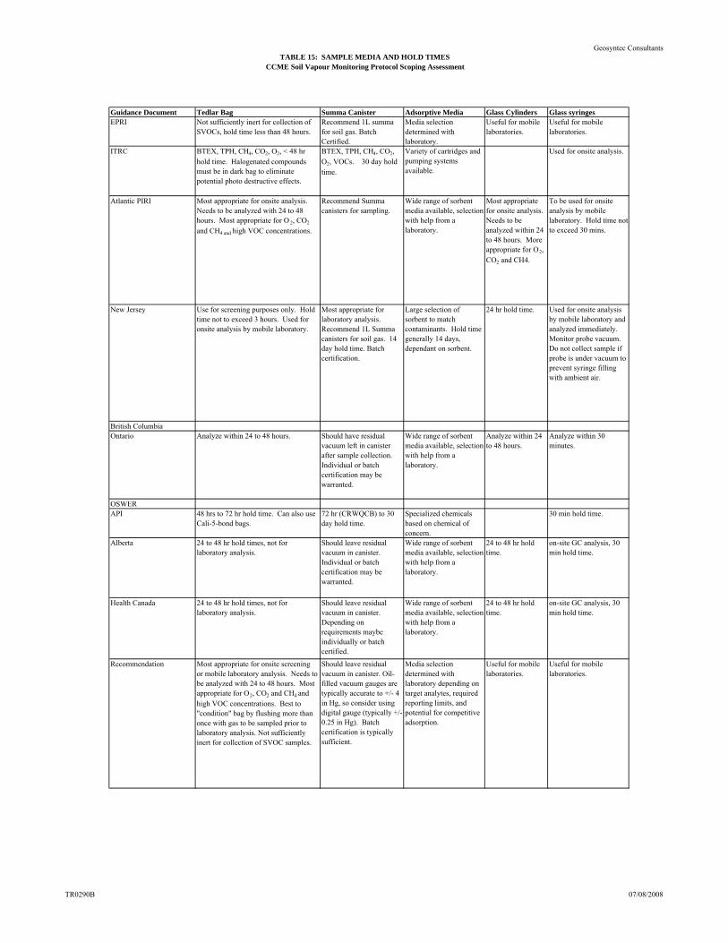
TABLE 15: SAMPLE MEDIA AND HOLD TIMESCCME Soil Vapour Monitoring Protocol Scoping Assessment
Geosyntec Consultants
Guidance Document Tedlar Bag Summa Canister Adsorptive Media Glass Cylinders Glass syringesEPRI Not sufficiently inert for collection of
SVOCs, hold time less than 48 hours.Recommend 1L summa for soil gas. Batch Certified.
Media selection determined with laboratory.
Useful for mobile laboratories.
Useful for mobile laboratories.
ITRC BTEX, TPH, CH4, CO2, O2, < 48 hr hold time. Halogenated compounds must be in dark bag to eliminate potential photo destructive effects.
BTEX, TPH, CH4, CO2, O2, VOCs. 30 day hold time.
Variety of cartridges and pumping systems available.
Used for onsite analysis.
Atlantic PIRI Most appropriate for onsite analysis. Needs to be analyzed with 24 to 48 hours. Most appropriate for O 2, CO2
and CH4 and high VOC concentrations.
Recommend Summa canisters for sampling.
Wide range of sorbent media available, selection with help from a laboratory.
Most appropriate for onsite analysis. Needs to be analyzed within 24 to 48 hours. More appropriate for O2, CO2 and CH4.
To be used for onsite analysis by mobile laboratory. Hold time not to exceed 30 mins.
New Jersey Use for screening purposes only. Hold time not to exceed 3 hours. Used for onsite analysis by mobile laboratory.
Most appropriate for laboratory analysis. Recommend 1L Summa canisters for soil gas. 14 day hold time. Batch certification.
Large selection of sorbent to match contaminants. Hold time generally 14 days, dependant on sorbent.
24 hr hold time. Used for onsite analysis by mobile laboratory and analyzed immediately. Monitor probe vacuum. Do not collect sample if probe is under vacuum to prevent syringe filling with ambient air.
British ColumbiaOntario Analyze within 24 to 48 hours. Should have residual
vacuum left in canister after sample collection. Individual or batch certification may be warranted.
Wide range of sorbent media available, selection with help from a laboratory.
Analyze within 24 to 48 hours.
Analyze within 30 minutes.
OSWERAPI 48 hrs to 72 hr hold time. Can also use
Cali-5-bond bags.72 hr (CRWQCB) to 30 day hold time.
Specialized chemicals based on chemical of concern.
30 min hold time.
Alberta 24 to 48 hr hold times, not for laboratory analysis.
Should leave residual vacuum in canister. Individual or batch certification may be warranted.
Wide range of sorbent media available, selection with help from a laboratory.
24 to 48 hr hold time.
on-site GC analysis, 30 min hold time.
Health Canada 24 to 48 hr hold times, not for laboratory analysis.
Should leave residual vacuum in canister. Depending on requirements maybe individually or batch certified.
Wide range of sorbent media available, selection with help from a laboratory.
24 to 48 hr hold time.
on-site GC analysis, 30 min hold time.
Recommendation Most appropriate for onsite screening or mobile laboratory analysis. Needs to be analyzed with 24 to 48 hours. Most appropriate for O2, CO2 and CH4 and high VOC concentrations. Best to "condition" bag by flushing more than once with gas to be sampled prior to laboratory analysis. Not sufficiently inert for collection of SVOC samples.
Should leave residual vacuum in canister. Oil-filled vacuum gauges are typically accurate to +/- 4 in Hg, so consider using digital gauge (typically +/- 0.25 in Hg). Batch certification is typically sufficient.
Media selection determined with laboratory depending on target analytes, required reporting limits, and potential for competitive adsorption.
Useful for mobile laboratories.
Useful for mobile laboratories.
TR0290B 07/08/2008
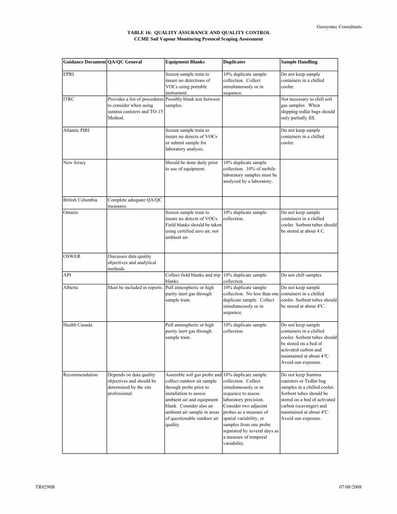
TABLE 16: QUALITY ASSURANCE AND QUALITY CONTROLCCME Soil Vapour Monitoring Protocol Scoping Assessment
Geosyntec Consultants
Guidance Document QA/QC General Equipment Blanks Duplicates Sample Handling
EPRI Screen sample train to insure no detections of VOCs using portable instrument.
10% duplicate sample collection. Collect simultaneously or in sequence.
Do not keep sample containers in a chilled cooler.
ITRC Provides a list of procedures to consider when using summa canisters and TO-15 Method.
Possibly blank test between samples.
Not necessary to chill soil gas samples. When shipping tedlar bags should only partially fill.
Atlantic PIRI Screen sample train to insure no detects of VOCs or submit sample for laboratory analysis.
Do not keep sample containers in a chilled cooler.
New Jersey Should be done daily prior to use of equipment.
10% duplicate sample collection. 10% of mobile laboratory samples must be analyzed by a laboratory.
British Columbia Complete adequate QA/QC measures.
Ontario Screen sample train to insure no detects of VOCs. Field blanks should be taken using certified zero air, not ambient air.
10% duplicate sample collection.
Do not keep sample containers in a chilled cooler. Sorbent tubes should be stored at about 4 C.
OSWER Discusses data quality objectives and analytical methods.
API Collect field blanks and trip blanks.
10% duplicate sample collection.
Do not chill samples
Alberta Must be included in reports. Pull atmospheric or high purity inert gas through sample train.
10% duplicate sample collection. No less than one duplicate sample. Collect simultaneously or in sequence.
Do not keep sample containers in a chilled cooler. Sorbent tubes should be stored at about 4ºC.
Health Canada Pull atmospheric or high purity inert gas through sample train.
10% duplicate sample collection.
Do not keep sample containers in a chilled cooler. Sorbent tubes should be stored on a bed of activated carbon and maintained at about 4ºC. Avoid sun exposure.
Recommendation Depends on data quality objectives and should be determined by the site professional.
Assemble soil gas probe and collect outdoor air sample through probe prior to installation to assess ambient air and equipment blank. Consider also an ambient air sample in areas of questionable outdoor air quality.
10% duplicate sample collection. Collect simultaneously or in sequence to assess laboratory precision. Consider two adjacent probes as a measure of spatial variability, or samples from one probe separated by several days as a measure of temporal variability.
Do not keep Summa canisters or Tedlar bag samples in a chilled cooler. Sorbent tubes should be stored on a bed of activated carbon (scavenger) and maintained at about 4ºC. Avoid sun exposure.
TR0290B 07/08/2008
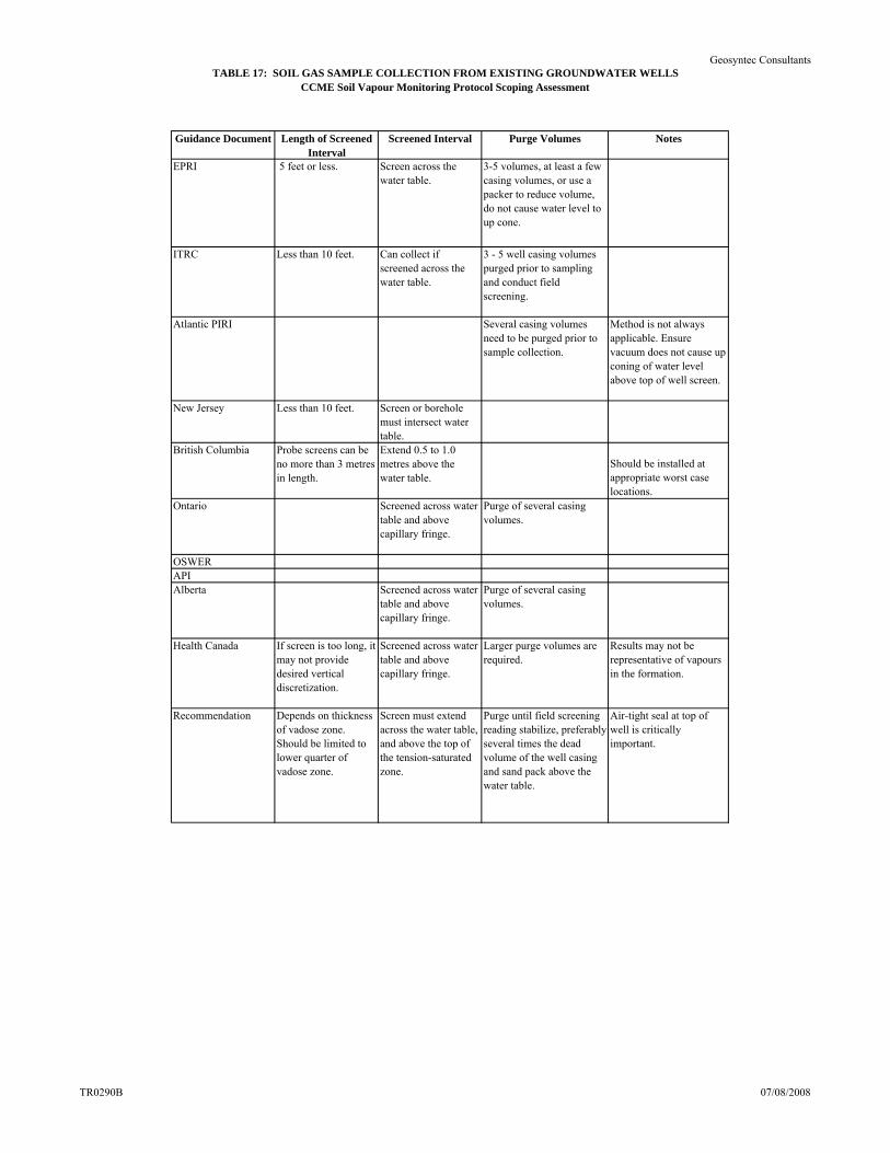
TABLE 17: SOIL GAS SAMPLE COLLECTION FROM EXISTING GROUNDWATER WELLSCCME Soil Vapour Monitoring Protocol Scoping Assessment
Geosyntec Consultants
Guidance Document Length of Screened Interval
Screened Interval Purge Volumes Notes
EPRI 5 feet or less. Screen across the water table.
3-5 volumes, at least a few casing volumes, or use a packer to reduce volume, do not cause water level to up cone.
ITRC Less than 10 feet. Can collect if screened across the water table.
3 - 5 well casing volumes purged prior to sampling and conduct field screening.
Atlantic PIRI Several casing volumes need to be purged prior to sample collection.
Method is not always applicable. Ensure vacuum does not cause up coning of water level above top of well screen.
New Jersey Less than 10 feet. Screen or borehole must intersect water table.
British Columbia Probe screens can be no more than 3 metres in length.
Extend 0.5 to 1.0 metres above the water table.
Should be installed at appropriate worst case locations.
Ontario Screened across water table and above capillary fringe.
Purge of several casing volumes.
OSWERAPIAlberta Screened across water
table and above capillary fringe.
Purge of several casing volumes.
Health Canada If screen is too long, it may not provide desired vertical discretization.
Screened across water table and above capillary fringe.
Larger purge volumes are required.
Results may not be representative of vapours in the formation.
Recommendation Depends on thickness of vadose zone. Should be limited to lower quarter of vadose zone.
Screen must extend across the water table, and above the top of the tension-saturated zone.
Purge until field screening reading stabilize, preferably several times the dead volume of the well casing and sand pack above the water table.
Air-tight seal at top of well is critically important.
TR0290B 07/08/2008
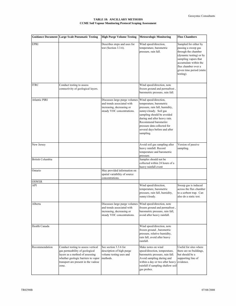
TABLE 18: ANCILLARY METHODSCCME Soil Vapour Monitoring Protocol Scoping Assessment
Geosyntec Consultants
Guidance Document Large Scale Pneumatic Testing High Purge Volume Testing Meteorologic Monitoring Flux Chambers
EPRI Describes steps and uses for test (Section 3.3.6).
Wind speed/direction, temperature, barometric pressure, rain fall.
Sampled for either by passing a sweep gas through the chamber (dynamic testing) or by sampling vapors that accumulate within the flux chamber over a given time period (static testing).
ITRC Conduct testing to assess connectivity of geological layers.
Wind speed/direction, note frozen ground and permafrost , barometric pressure, rain fall.
Atlantic PIRI Discusses large purge volumes and trends associated with increasing, decreasing or steady VOC concentrations.
Wind speed/direction, temperature, barometric pressure, rain fall, humidity, sunny/cloudy. Soil gas sampling should be avoided during and after heavy rain. Recommend barometirc pressure data collected for several days before and after sampling.
New Jersey Avoid soil gas sampling after heavy rainfall. Record temperature and barometric pressure.
Version of passive sampling.
British Columbia Samples should not be collected within 24 hours of a heavy rainfall event
Ontario May provided information on spatial variability of source concentrations.
OSWERAPI Wind speed/direction,
temperature, barometric pressure, rain fall, humidity, sunny/cloudy.
Sweep gas is induced across the flux chamber to a sorbent trap. Can also do a static test.
Alberta Discusses large purge volumes and trends associated with increasing, decreasing or steady VOC concentrations.
Wind speed/direction, note frozen ground and permafrost , barometric pressure, rain fall, avoid after heavy rainfall.
Health Canada Wind speed/direction, note frozen ground , barometric pressure, relative humidity, rain fall, avoid after heavy rainfall.
Recommendation Conduct testing to assess vertical gas permeability of geological layers as a method of assessing whether geologic barriers to vapor transport are present in the vadose zone.
See section 3.3.6 for description of high purge volume testing uses and methods.
Make notes on wind speed/direction, temperature, barometric pressure, rain fall. Avoid sampling during and within a day or two after heavy rainfall if sampling shallow soil gas probes.
Useful for sites where there are no buildings, but should be a supporting line of evidence.
TR0290B 07/08/2008


![Sediment Management - Geosyntec · Sediment Management 4UBUFNFOUPG2VBMJmDBUJPOT] About Geosyntec Section 1 About Geosyntec Technical Excellence, Teamwork and A Generous Spirit Recognized](https://img.pdfslide.net/doc/110x75/5d5dcc7788c993a30e8b8011/sediment-management-sediment-management-4ubufnfoupg2vbmjmdbujpot-about-geosyntec.jpg)