Embed Size (px)
DESCRIPTION
air studio final journal
Citation preview

ARCHITECTURE DESIGN STUDIO
AIR
DALONG HE 371606TUTOR: MICHAEL & ZAK
CONTENTS
PART A CASE FOR INNOVATION
1.1 INTRODUCTION1.2 ARCHITECTURE AS A DISCOURSE
1.3 COMPUTATION IN ARCHITECTURE 1.4 PARAMETRIC MODELLING
1.5 ALGORITHMIC EXPLORATIONS1.6 CONCLUSION
1.7 LEARNING OUTCOMES
PART B DESIGN APPROACH PART C PROJECT PROPOSAL

PART A CASE FOR INNOVATION

A 1.1 INTRODUCTION
My name is Dalong He (leon)
I am an international student from China and I’m doing my third year
study with the major of architecture. Unlike some other students who
has their explicit target to be an architect, I’ve no explicit goal to do
this, so that I didn’t take any extra training for this major. I do not have
a good groundwork for this subject.
I’ve learning the Rhino in the virtual environment in the first year, and
begin to touch the digital architecture, but only have the basic abili-
ty to use Rhino. And then I’ve learnt the CAD, Photoshop, InDesign
and Revit during my two years study. Also, I only learnt the basic use
of those software. During the study in the last two years, I am quite
interested in the digital architecture and I’m glad to learn the digital
architectural technologies in-depth.

This is my project for water design studio in last semester: the YarraBend Park boat-house design. This design idea was by studying Avral Siza’s Tea House. The building is face the Yarra River, and contains a café, a restaurant and a boat storage, which follow the old boathouse’s function. The design is designed by follow the landscape of the park, to avoid destroy the natural environment there. This is a multiple stories building, the first floor contains the café and the restaurant and the north walls, which is face the river are all glass curtain wall, that can allow the people can see the scenery on the river while they having the meal and the coffee. And there is a kiosk and boat storage and also a public bathroom to service people who go there have fun. Between the boathouse and the bank of the river there is a courtyard to allow people play there, and close to the water, the nature. By learning Siza’s works, light is conspicuous factor in his works, so I’ve designed some elements to allow the light come in the internal of the building. Since my whole building is an additive form, so the area of the first floor is larger than the ground floor, that can make a cover to the courtyard, which can protect people to avoid the sunburn. And also can make a beautiful shade for the courtyard, because I’ve made the first floor board with some small holes pattern.
A 1.1 INTRODUCTION

A1.2 ARCHITECTURE AS A DISCOURSE
‘architecture needs to be thought of less as a set of special material
products and rather more as range of social and professional practic-
es that sometimes, but by no means always, lead to buildings.’1
--Williams, Richard (2005)
1.Williams, Richard (2005). ‘Architecture and Visual Culture’, in Exploring Visual Culture: Definitions, Concepts, Contexts, ed. By Mat-thew Ram pley (Edinburgh: Edinburgh University Press), pp. 108

A1.2 ARCHITECTURE AS A DISCOURSE
What is architecture? Architecture (building) was originally used as a shelter.
With the developing of the society, architecture has also kept developing with the social changes. During the historical developments in architectural realm, there are lots of building types, and architectural concepts, such as Classical building, Re-naissance building, Baroque, Modernism etc. In now days, architecture has quite a different meaning from the original one which is the function of shelter, rather than reflecting social culture. In other words, architecture could be tread as a discourse of the culture and the arts. Regard to Williams Richard (2005) ‘the architect is a special kind of artist who works in three dimensions’2 . It could not only reflect to the manner of architect, but also reflect the local tradition culture.
2. Williams, Richard (2005). ‘Architecture and Visual Culture’, in Exploring Visual Culture: Definitions, Concepts, Contexts, ed. By Matthew Rampley (Edinburgh: Edinburgh University Press), pp. 103

Boa Nava tea House Source: http://insituarchitecture.files.wordpress.com/2010/09/tea-house-stitch.jpg
Boa Nova tea House is quite a good example, which can represent the architect’s manner and the local culture. Tea house is Alvaro Siza’s early work, in his early work, there is an obvious feature which is native complex, since his main idea has formed in 1950s, which is an important period in Portugal. At that time, Portugal start to open its country to the world, the difference between Portugal and the world, has stimulated the development of architec-ture. Base on the background, Siza’s early work has tried to use the modern technique to represent the tradition of Portugal.
Look at the building, the whole building size and the form of the roof make it looks like grow from the rocky straits area. The layout has reflected the construction and geo-logical structure adapted to processing method. The varie-ty design of opening windows and the doors in the space, enhanced in different ways with the connection between the interior and the surrounding landscape. The eaves have revealed quite deep, the annatto smallpox that ex-tends outside has provided a protection which can reduce the strong sunshine on the local site. In addition, the shed roof which covered by worm red floor tile, the wood board decorate, white wall etc. all of above has reflected Siza’s pursue for the architectural tradition of Portugal.
Eaves of the Tea Househt t p : / / 2 4 . m e d i a . t u m b l r. c o m / t u m -blr_mbqdw75Joa1r56udmo1_1280.jpg
Roof of the Tea Househ t t p : / / f a r m 8 . s t a t i c . f l i c k r .com/7118/7809466362_8933b15a67.jpg
PRECEDENT

Boa Nava tea House Source: http://insituarchitecture.files.wordpress.com/2010/09/tea-house-stitch.jpg
National Aquatics Centre in BeijingSource: http://www.jinpaiw.com/userfiles/200872415222032696%E6%B0%B4%E7%AB%8B%E6%96%B9%282%29.jpg
Beijing National Aquatics Centre (commonly known as the ‘water cube’), it is one of the landmark building of Beijing Olympic Games in 2008. Its original design inspiration comes from the structure of the water molecules. The design project is ‘water cube’, which come from the global design competition. The design is according to the cell ar-rangement and soap bubbles natural structure, it is a totally new structure, which has never appeared in architectural realm.
The deceptively simple ‘box’ was ‘constructed’ by the traditional culture and the modern technology. Chinese people believe that nothing can be accomplished without norms or standards. In Chinese traditional culture, the cube form is according with the old idea of ‘tianyuandifang’ which mean the earth was square and the heaven was round with relating to the rounded ‘bird’s nest’ which is the national stadium. Square is the basic constructional form of Chinese ancient city, it reflects the ethical rules of the social life in Chinese cultural. Also, the ‘box’ can embody all requires of the national Aquatics Centre, so it achieve the perfect combination of traditional culture and architectural features.
PRECEDENT

Structure of the water moleculeSource: http://baike.baidu.com/picview/779442/779442/0/ac0acf13e92dbd435baf533b.html#albu-mindex=3&picindex=4
Steel skeleton renderingSource: http://baike.baidu.com/picview/779442/779442/0/b3ba5d-1689c6700b21a4e903.html#album-index=3&picindex=12
National Aquatics Centre & ‘bird nest’Source: http://www.otis.com/site/cn-eng/OT_DL_CommonImages/%E6%B0%B4%E7%AB%8B%E6%96%B9%E5%92%8C%E9%B8%9F%E5%B7%A2.jpg
PRECEDENT
In Chinese culture, water is an important natural factors, it can arouse people’s hap-piness mood. The ‘water cube’ has become the biggest aquatic park in Beijing.

A 1.2 COMPUTATION IN ARCHITECTURE
‘Design is a process we engage in when the current situation is different
from some desired situation, and when the actions needed to transform the
former into the latter is not immediately obvious’3
- -Kalay, Yehuda E. (2004)
3. Kalay, Yehuda E.(2004). Architecture’s New Media: Principles, Theories, and Methods of Computer-Aided Design (Cambridge, MA: MIT Press) pp.5
A 1.2 COMPUTATION IN ARCHITECTURE
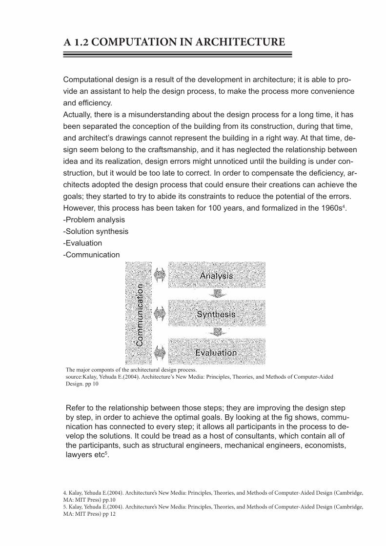
The major componts of the architectural design process. source:Kalay, Yehuda E.(2004). Architecture’s New Media: Principles, Theories, and Methods of Computer-Aided Design. pp 10
Computational design is a result of the development in architecture; it is able to pro-vide an assistant to help the design process, to make the process more convenience and efficiency. Actually, there is a misunderstanding about the design process for a long time, it has been separated the conception of the building from its construction, during that time, and architect’s drawings cannot represent the building in a right way. At that time, de-sign seem belong to the craftsmanship, and it has neglected the relationship between idea and its realization, design errors might unnoticed until the building is under con-struction, but it would be too late to correct. In order to compensate the deficiency, ar-chitects adopted the design process that could ensure their creations can achieve the goals; they started to try to abide its constraints to reduce the potential of the errors. However, this process has been taken for 100 years, and formalized in the 1960s4.-Problem analysis-Solution synthesis-Evaluation-Communication
4. Kalay, Yehuda E.(2004). Architecture’s New Media: Principles, Theories, and Methods of Computer-Aided Design (Cambridge, MA: MIT Press) pp.105. Kalay, Yehuda E.(2004). Architecture’s New Media: Principles, Theories, and Methods of Computer-Aided Design (Cambridge, MA: MIT Press) pp 12
Refer to the relationship between those steps; they are improving the design step by step, in order to achieve the optimal goals. By looking at the fig shows, commu-nication has connected to every step; it allows all participants in the process to de-velop the solutions. It could be tread as a host of consultants, which contain all of the participants, such as structural engineers, mechanical engineers, economists, lawyers etc5.

Hand drawing floor plansource: http://3.bp.blogspot.com/_ObnPGzc7YDk/Rcdghuh_ydI/AAAAAAAAAdQ/H87IxvEzrEE/s400/AMG+showroom+design2.jpg
A 1.2 COMPUTATION IN ARCHITECTURE
The computational architecture has provided a communication platform, which can expand the access of information and open up the design process for more people6.For another aspect, with the developing of the computational architecture, there are lots of new technologies appeared in the architectural realm, which particular refer to the architectural soft-ware, such as Rhino, CAD, Revit etc. They all can help the archi-tectural design process operate in an easy way, which compare to the hand drawing and model making. Because it can easily work out the solution with the connection of the architecture & building, and the material & products, and easily make a test . The figures on the right have shown the relationship of the architecture & building, the material & products7.
6. Kalay, Yehuda E.(2004). Architecture’s New Media: Principles, Theories, and Methods of Computer-Aided Design (Cambridge, MA: MIT Press) pp 137. Kieran, Stephen, and James Timberlake (2004). Refabricating Architecture: How Manufacturing Methodologies are Poised to Transform Building Construction (New York: McGraw-Hill). pp. 12, 15, 23.
Floor plan by computerSource: http://1.bp.blogspot.com/_N8OYvx8SZ90/TMTxqvhpy9I/AAAAAAAAAA8/jSvmyquauLo/s1600/Presentation+board+4.jpg
The two plans on the left is two floor plans, which come from the website, they can show the benefit of using computer to draw a plan (below), it is much more clear and make more sense to the client. On the other hand the hand draw one (above) is unclear to show the representation of the plan, it cannot show the wall type, the accurate data of the building such as the dimension. In addition, using computer can change the plan easily while there appear some mis-take.

The research ICD/IRKE Research Pavilion 2010 gives an evidence of computational design. Its physical form is decided by the pressure, since the material construct is able to be considered as a consequent from a system of internal and external pressures and constraints. On the other hand, the digital design process in architecture could infrequently reflect to these relations. Because of the material form is always inseparably related to external forces in the physical realm. However, in the computational architecture, the digital design form and force are often treated as separate entities, because they are ‘divided into processes of geometric form generation and subsequent simulation based on specific material properties’8 .
8. Institute for Computational Design 2010 ICD Research Project http://icd.uni-stuttgart.de/?p=4458 viewed 26th March
Fig 3 ICD/IRKE Research Pavilion 2010 (source:http://icd.uni-stuttgart.de/?p=4458)
PRECEDENT

PRECEDENT
By look ing a t the p ic tures o f the d ig i ta l mode ls (no t completed) we can see there are thousands lines need to draw during the computational process, it seems impossible to draw them by hand. Also, the digital model could be test by the computational process, and that will avoid the material waste, since the computer can provide the accurate data of the structure and material’s character.
4ICD/IRKE Research Pavilion 2010 (source:http://icd.uni-stuttgart.de/?p=4457)
4ICD/IRKE Research Pavilion 2010 (source:http://icd.uni-stuttgart.de/?p=4458)
PRECEDENT
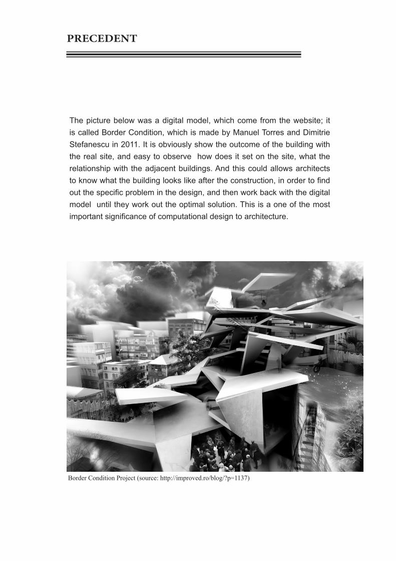
Border Condition Project (source: http://improved.ro/blog/?p=1137)
The picture below was a digital model, which come from the website; it is called Border Condition, which is made by Manuel Torres and Dimitrie Stefanescu in 2011. It is obviously show the outcome of the building with the real site, and easy to observe how does it set on the site, what the relationship with the adjacent buildings. And this could allows architects to know what the building looks like after the construction, in order to find out the specific problem in the design, and then work back with the digital model until they work out the optimal solution. This is a one of the most important significance of computational design to architecture.

Computational process could make the architecture more visual, since we can easily observe the outcome of the design with the site condition. Rather than just a single which cannot show any relationship with the surroundings, even a physical model with a site model are also lack of visual effect of the design.
PRECEDENT
Building Model, Southeast Exposure (source::http://www.miasci.org/blog/post-title-1)
Building Moderl (source: http://yehuna.deviantar t .com/ar t /S tardus t -Tech-Building-Model-251687788)

A1.4 PARAMETRIC MODELLING
‘Parametric is a set of equations that express a set of quantities as explicit functions of a number of independent variables, known as ‘parameters’” --Weisstein 2003, 2150

Parametric design is an emerging concept of design process which the parameters are interconnected as a system. One parameter’s change would affect the whole network and causes global influence. Parametric design creates systematic, adaptive variation, continuous differentiation, and dynamic figuration from the scale of urbanism to the scale of architecture, interior and furniture. Designer can acquire different designing schemes. It could be simply understood as a method that can generate designing scheme automatically by the computational technology. And this could be accorded to Woodbury, Robert (2010) ‘Parametric modeling represents change’9. Unlike the conventional design systems, which use pencil, eraser and paper to add or subtract marks on papers. Parametric modeling presents an essential change, which is make the ‘marks’ as parts of a design, and then they could be changed together in a coordinated way10 . Two key techniques of the parametric modeling: geometric construction and programming. Geometric construction contains making sequence of simple operations to solve problems. Even though they are simple operations, almost all constructions can be done in different ways with the parametric system. For instance, fig 1 & 2 has shown the distinct ways to construct a tangent from a point to a circle, and fig 3 has shown a more complex construction with finding the tangent line between two circles. ‘Programming writing algorithms that either build models or works as update algorithms in their own right’11 .
The most popular parametric design platform is composed of rhino and grasshopper, since the powerful modeling ability of rhino and the particular visual programming method.
A1.4 PARAMETRIC MODELLING
9. Woodbury, Robert (2010). Elements of Parametric Design (London: Routledge) pp.7 10. Woodbury, Robert (2010). Elements of Parametric Design (London: Routledge) pp.1111. Woodbury, Robert (2010). Elements of Parametric Design (London: Routledge) pp.22
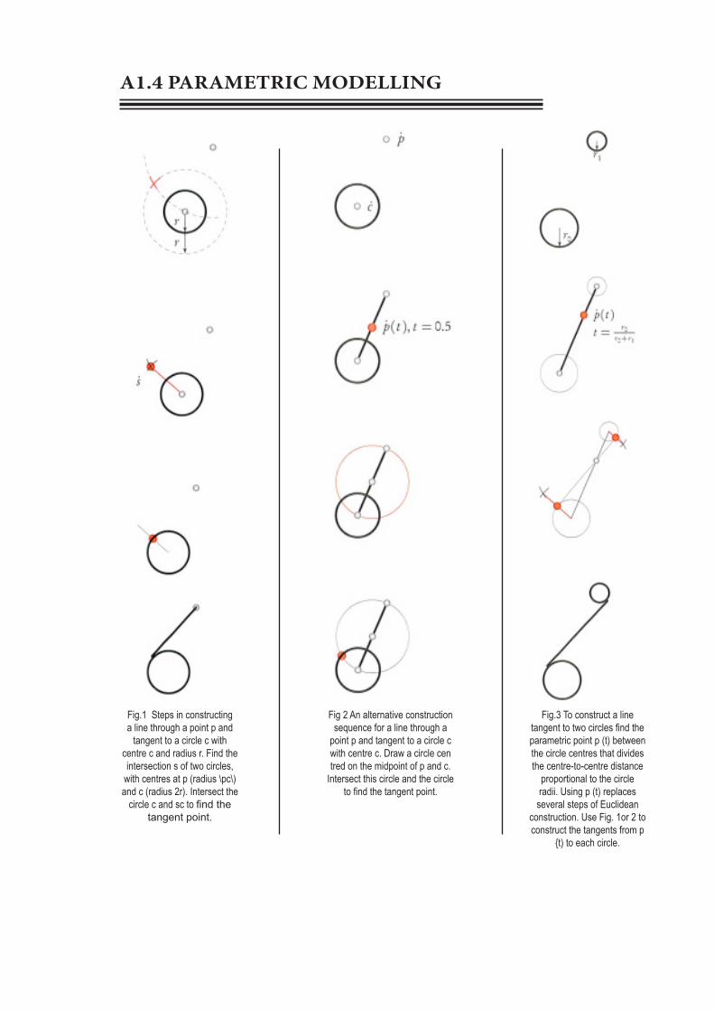
Fig.3 To construct a line tangent to two circles find the parametric point p (t) between the circle centres that divides the centre-to-centre distance
proportional to the circle radii. Using p (t) replaces
several steps of Euclidean construction. Use Fig. 1or 2 to construct the tangents from p
{t) to each circle.
Fig 2 An alternative construction sequence for a line through a
point p and tangent to a circle c with centre c. Draw a circle cen tred on the midpoint of p and c.
Intersect this circle and the circle to find the tangent point.
Fig.1 Steps in constructing a line through a point p and
tangent to a circle c with centre c and radius r. Find the intersection s of two circles,
with centres at p (radius \pc\) and c (radius 2r). Intersect the
circle c and sc to find the tangent point.
A1.4 PARAMETRIC MODELLING

Galaxy SOHO, BeiJing. (source:http://1.bp.blogspot.com/-psVsRVb30Go/UI_0FDiFrYI/AAAAAAAANaM/E_WfEY54CRg/s1600/Galaxy+Soho+by+Zaha+Hadid+Architects+07.jpg)
'Paramet r i c mode l ing opens new windows to design' --Woodbury, Robert (2010)
The Galax Soho in Beijing is a new landmark building, which is designed by Zaha Hadid. In the design, Hadid has created a continuous flow of space with the parametric design method, it is an area of 50000 square meters, a total construction area of nearly 330000 square meters of 360 degrees without dead angle of the architectural world. This building has used CATIA/Digital Project. The use of parametric platform was fundamental not only as strong geometric modeller, but also as the repository tool, clash analysis and corrdination of different packages. It also enabled the designer to quickly text iterations and has an accurate account of areas and bill of, materials12.
In the design process of carious parameters are linked together into a system, consider to the character of the parametric design, a parameter change will cause a global impact.
12. Web source : http://uk.linkedin.com/in/rolandorodriguezleal viewed 3ed April

PRECEDENT
There are some application of traditional Chi-nese cultural elements, courtyard and terrace, courtyard often representing the polymerization and emotional blend. Zaha hopes to courtyard to create a happy world, that’s why there is no longer cold rectangular blocks separated rather than create a continuous and common evolu-tion form.

PRECEDENT
National Stadium in BeijingSource : http://www.3366ok.com/upimg/allimg/081228/1536330.jpg
The National Stadium in Beijing (known universally as the ‘Bird’s Nest’) is a typical example of a parametric design. It was designed by Jacques Herzog, De Meuron and Li Xinggang, form as the ‘nest’ of life, it is more like a cradle, which the human hope for the future. The designers didn’t do any extra processing to the national stadium, but exposed the struc-ture on outside, thus naturally formed the appearance of the building. It was service for the Olympic Game in 2008, after that it was become a park for people to play and visit, also conduct some competitions some-time.

By look at the messy structure, it is clearly show that this is a parametric design, the picture above has shown a parametric model in digital project of its roof, beginning from wire frame roof geometry, and subsequently adding a suite of adaptable user-feature components to build the box girder and connector element assemblies. During design of process the National Stadium, the time was very tight; in this case, the benefit of the parametric design was embodied, since parametric modelling in digital project enabled basic redesign, which means it can be easy to operate with computer to fix the problem of the design.
PRECEDENT
Parametric Model of the National StadiumSource: http://web.arch.usyd.edu.au/~rob/teaching/2008/DECO2013/lectures/DE-CO2013-Lecture-06.pdf
Digital Model of the National StadiumSource: http://24.media.tumblr.com/21ac2366d1480430d05f447c450894a9/tumblr_mipzx5ZEif1rmu8ppo4_1280.jpg

1.5 ALGORITHMIC EXPLORATIONS
These are parts of my explorations of algorithmic work flows within Grasshopper. The first one was practice with the curve and loft, in this project, there are two prob-lems I’ve met when I was doing this excise, one is the point, which is when doing the arch with 3 point, the points on the three curves are normally not aligning, so we need another order which is the point-list, it can make the points align. Another one is when I did the loft operate it cannot be make a whole surface, part of the curve cannot be lofted, and this need to rebuild the model. The reason that I’ve like this work is that, I’ve been doing this model by thinking of the Bird’s Nest, I think I’ve got the original shape, but need more working to achieve the goal.
1.5 ALGORITHMIC EXPLORATIONS
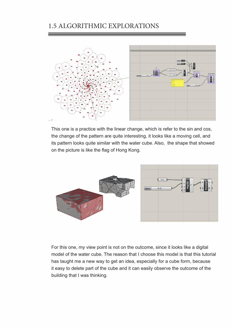
This one is a practice with the linear change, which is refer to the sin and cos, the change of the pattern are quite interesting, it looks like a moving cell, and its pattern looks quite similar with the water cube. Also, the shape that showed on the picture is like the flag of Hong Kong.
For this one, my view point is not on the outcome, since it looks like a digital model of the water cube. The reason that I choose this model is that this tutorial has taught me a new way to get an idea, especially for a cube form, because it easy to delete part of the cube and it can easily observe the outcome of the building that I was thinking.

1.5 ALGORITHMIC EXPLORATIONS
This one I put here is showing that the operating principle of the paramet-ric design, which is by changing the parameter to get different solutions, in order to allow the designer to compare different ideas and find out the optimal solution. In grasshopper, the number slider is the parameter, it can represent number, length, radius etc, every variable can use number slider to change, and I think this should be the base of the parametric design.

1.6 CONCLUSION
This is a quite interesting subject, and also very useful subject. By exploring the issue of architecture as a discourse, which is the main concept in this part, we can easily to understand what architecture is. There should have lots of different ideas about what it is, so that we have to have our own opinion, because there is nothing incorrect, architecture is a quite a large realm. ‘There is no debate for taste’ this is a word in the aesthetic theory; it also suitable for the architecture, there has no accurate answers for this question. My argument in this case is architecture as arts and can reflect on the native traditional culture. Architecture has the characters about the regionalism and humanism, which it will different with different region and different people. That because the different region has different culture. Even though with the development of the architecture, but it always can reflect on the culture. The computational design is the result of the development, it has provided a convenient tool to architecture, and it makes the design process more efficient. The parametric modelling is a newborn concept; it is the main aspect of the computational design, and it the parametric modelling is facing the future.

A 1.7 LEARNING OUTCOMES
By studying during the past four weeks, I’ve realize that this sub-ject should be focus on the parametric modelling, since rhino and grasshopper is the main tool that can do he parametric design. During the study and practice with grasshopper, I’ve found that this is a really good software to use. And parametric design is quite an awesome method to do the design process. It is very magical process with only change a parameter will affect the whole outcome, and the parametric model has a totally different outcome from the traditional architecture, its outcome is much flashier than any type of architecture in the history. It has broken the normal rule of architecture, it idea is dauntless and full of imagination. However, although parametric design can provide us a lot of shapes, but we still need to choose from them, since it is always a messy design, so every parametric design need to lots of modification, since it is impossible to make a perfect solution. So the aim of this semester for me is that learning Rhino and grass-hopper, the ability of using parametric design.

PART A CASE FOR INNOVATION
PART B DESIGN APPROACH
2.1 DESIGN FOCUS2.2 CASE STUDY 1.0 2.3 CASE STUDY 2.0
2.4 TECHNIQUE: DEVELOPMENT 2.5. TECHNIQUE: PROTOTYPES
2.6. TECHNIQUE PROPOSAL 2.7. ALGORITHMIC SKETCHES
2.8. LEARNING OBJECTIVES AND OUTCOMES
PART C PROJECT PROPOSAL

B 1. DESIGN FOCUS
SECTIONING
As we are asked to specialise in an area of interest to narrow the design pos-sibilities, we were interest in the sectioning, which a kind structure that made by cutting a three-dimensional object to create the sheet structure. The main reason that we choose the sectioning is because the site is a high way space, which is a quite open space, so we thought that if we focus on the light perfor-mance, that might be an interesting start point. Sectioning patterns are quite good at playing with light, since the sheet structure can create variational shade under the light. In addition, the sectioning structure can respond the surround environment flexibly. It can be seen as a screen, since it’s not a solid object, it has space between every single sectioning pattern, so it can allow the scenery on the other side come through the “screen” to the users (in this case is for the drivers).
Source: http://www10.aeccafe.com/blogs/arch-showcase/files/2013/01/CZA_PA007_9374.jpg
Dynamic frame, which means the sectioning frame could provide a moveable effect, because it is not a continuous frame, every sectioning sheet is independent to others, so people will see the change and move-ment when they drive along the sectioning frame.

B 1.1 PRECEDENT
BANQ RESTAURANT
Source: http://www.yatzer.com/BANQ-restau-rant-by-Office-dA
Located at the base of the old bank-ing hall of old Penny Savings Bank. It was divided into two segments, the bar and dining area which the larger hall behind serves. However the design of the space is concep-tualized around another division, on the z axis, between the ceiling and the ground. Below the ceiling, the functional aspects of a dining space are fabricated with warm woods and re-laminated bamboo amplifying the striping affect already at play throughout the space. This made the building quite organic and nature. Moreover, the Striations of the ground, the furnishings, and the ceiling all conspire to create a total effect, embedding the diners into the grain of the restaurant.13
In addition, the sectioning pattern in the Banq with a smooth curves can also give a flow effect, which is rep-resent the dynamic characteristic of the sectioning frame.
Source: http://www.yatzer.com/BANQ-restaurant-by-Office-dA
Why is this for Wyndham?
Since this project is for highway on the Wyndham, it is quite an open space, it’s good to use the light, the sectioning pattern can create some dramatic shades and a dynamic effect, which the sectioning can make a flow effect, which means this will give the drivers a moveable feeling with a high speed.

B1.2 ALGORITHMIC EXPLORATION
provide an image sam-pling routines
gener-ate a grid of {vu}
points on the surface(divide surface)
set a surface
find the extents of the surface
and create intersection planes
project an object onto a
planes
amolification of movement
create a lofted surface
through the section curves
section (solve intersection
events for the plan that create before)
This is a usage of the definition to make the banq restau-rant model

B1.2 ALGORITHMIC EXPLORATION
set a surface
section (solve intersection
events for the plan that create before)
Rep-resents a collection
of 3D
Generate a number of equally
spaced, perpendicular frames along the selected curve.
Extrude curves and surfaces
along the vector
Create a vector from {xyz}
components
This is another example of a simple definition of the sec-tioning.For our project we might use this definition as our start point, since we want to design a cave thing to cover one of the highway, and this seems can easily to achieve our outcome that we think.

B1.3 INTENTION
Our group is interested in sectioning; we decide to create a landmark sculpture for Wyndham. Experience the sculpture in different ways, which contain light, dynamic and motion.
We want people (drivers) can remember this site and getting know Wyndham city. As the site is quite a flat and static space, we were thinking that we can create something over the ground to make a con-trast with the surroundings, even though this might seems not harmoni-ous, but this is what we want to create, in order to attract drivers view, and when drivers go through, they will experience a change from light to dark (relative dark) and then back to light, at the same time they can also have a good experience to play with the shadow that create by the form. And the form will be design as a dynamic form to against the stat-ic environment. Also people will have a motion experience while they driving through this site.

B2.1 CASE STUDY 1.0 - MATRIX

B2.1 CASE STUDY 1.0 - MATRIX
This is a test with the definition in grasshopper, we tried to make some different outcomes by changing the image sampler, to change the different shape on the plan, the image sampler is to control the sectioning pattern in the z direction, which can make different shape with what the image show, in this test we want get the concave-convex texture on the surface, in order to make some differences on the sectioning patterns, but it seems only distinguish the black and white colour.
For this part, we were trying to decide our form as a cave as our starting point, just because this project is about the a gateway in a highway, so we want to create something that can allow the cars go through it, so the drivers can have a different experience when they driving through this site.
Then I start to consider what kind of experience the drivers will have, when they go through this site with the building that we might create, from our aim to create the gateway building, I toughly think that I can give the driver an special experience which a change from a wide area to a narrow area, and then back to the wide space, if this idea will work, drivers should feel a little bit nervous and constriction.
When we do some change with the original definition that we download from the LMS, I’ve found that sectioning can also give people a feel of motion, since it seems like some flow stuffs, so I think this could be another experience that can give the drivers.

B2.2 FITNESS CRITERIA
To choose these four outcomes, use the characteristic from each of them, I start to think the project of the gateway de-sign. As our intention is try to give the driver a contrast ex-perience, so we were interested in the cave surface and the form, the cave shape should not just an arch, it need to be made some change to change the wideness between the beginning and the end of the cave, and it also not necessary to make a whole cover to the road, because it would quite boring. We combine the good point that we think from the four outcomes we choose, try to create an outcome with half cover cave, different wideness, extruding surface and smooth frame ( to give a flow feeling) .In addition, sectioning is quite good at playing with light, so we will keep thinking what is the light effect we can achieve with the design
Extruding surface can provide a constriction feeling
Cave frame can restrict driver’s view in the gateway building.
The different wideness can also make people feel constriction
Smooth frame can represent motion, give drivers a flow feeling
B2.3 PRECEDENT
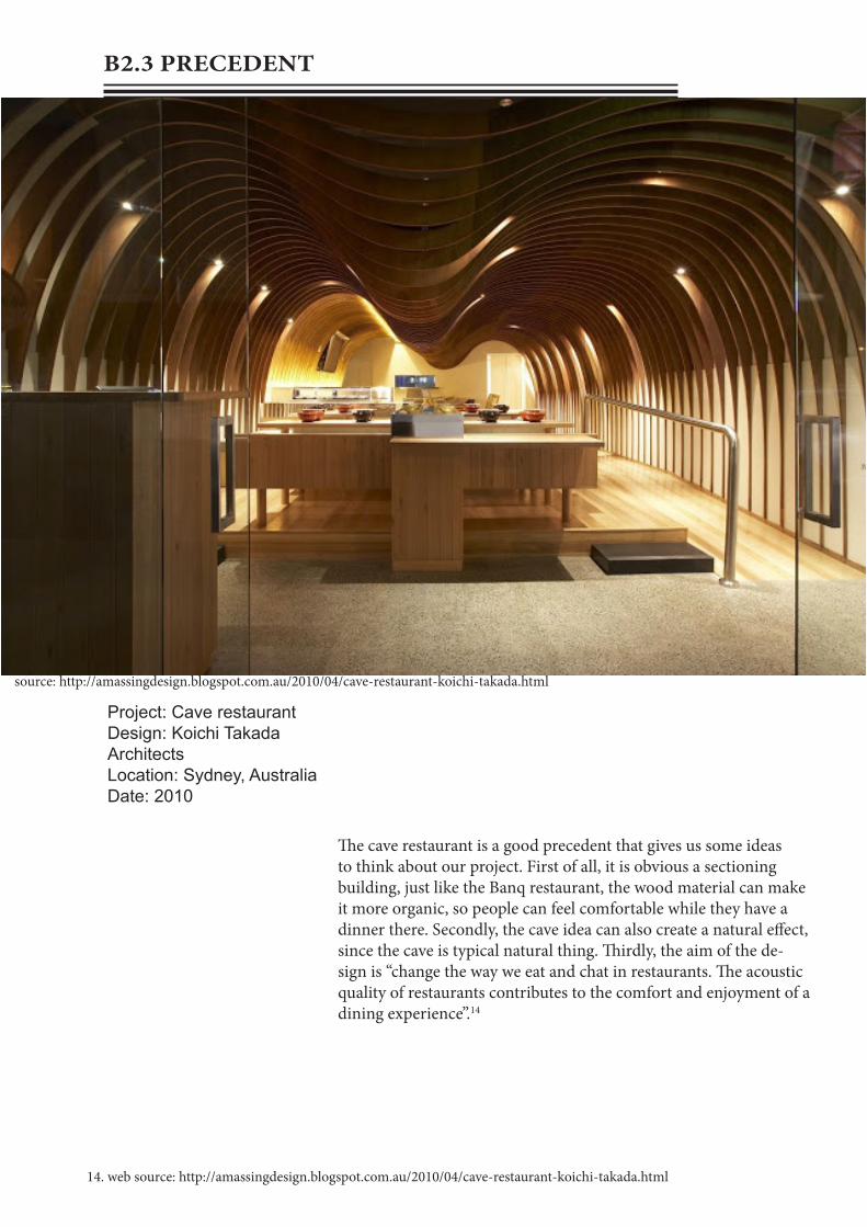
source: http://amassingdesign.blogspot.com.au/2010/04/cave-restaurant-koichi-takada.html
Project: Cave restaurantDesign: Koichi Takada ArchitectsLocation: Sydney, AustraliaDate: 2010
The cave restaurant is a good precedent that gives us some ideas to think about our project. First of all, it is obvious a sectioning building, just like the Banq restaurant, the wood material can make it more organic, so people can feel comfortable while they have a dinner there. Secondly, the cave idea can also create a natural effect, since the cave is typical natural thing. Thirdly, the aim of the de-sign is “change the way we eat and chat in restaurants. The acoustic quality of restaurants contributes to the comfort and enjoyment of a dining experience”.14
14. web source: http://amassingdesign.blogspot.com.au/2010/04/cave-restaurant-koichi-takada.html

B3. CASE STUDY 2.0
source:http://www.ydzsw.com/shownews.asp?id=10562 source: http://twistedsifter.com/2012/07/marilyn-monroe-absolute-tow-ers-by-mad-architects-mississauga/
The Marilyn Monroe Building (Absolute tower)Architects: MAD architects, BeijingProject architects: Ma Yansong, Yosuke Hayano, Dang QunPurpose: residentialCompletion: 2012Location: Mississauga, Canada
The Absolute Tower, it is an absolutely curved mansion as landmark architecture in Mississauga. People call it “The Marilyn Monroe Building” because of its beautiful profile. Its design manner does not just follow Simplifying Rules of Modernism any more, further it explains a kind of higher level complexity. The aim is to close to local society and life in diversity, as well as multiple demands. Some significant characteristic of this building as like continuous horizontal terraces surround whole building, the vertical lines which for emphasis altitude in traditional high-rise building are disap-peared. Whole building is processing a twisting in different perspectives and levels, which for corresponding different levels’ landscapes and contexts. Designers want The Marilyn Monroe Building wake up people’s longing to the nature, and to experience the effects of the sunlight and wind to people’s life15.
15. web source: http://www.ydzsw.com/shownews.asp?id=10562 viewed 8th May

B3. CASE STUDY 2.0
Why we choose this building?
This building has change the traditional form of the high building, which is the vertical lines, the form of the Monroe building is sort of an irregular form with some smooth curve surfaces. It has created a strong dynamic effect. Like the previous description of the building, the whole building is processing a twist-ing in different perspectives and levels, which for corresponding the land-scapes and context in different level.
We were tried to create an outcome which is looks like the Monroe building by using the definition and other knowledge that we’ve learnt of grasshopper in this subject. To think-ing the tools that we can use by looking the outcome of the building, we start to use the one of the definitions of our sectioning project. More important, it looks like an section-ing type building, so that it might useful for development of our project .
Step 1. Using the first definition to create a surface of cylinder as the basic sur-face, and a curve (line) to create a number of equally space, perpendic-ular frames along a curve. The frames will have intersection events for the brep that we set before, and then extrude them with xyz will get the sectioning outcome. But it is just a straight structure, not a twist surface that we want to achieve.

B3. CASE STUDY 2.0
Step 2
Then we were thinking to rotate this geometric that we created, in order to try to get the twist outcome, however, it only rotates with the axis as a whole group, which means we can only change it orientation, but not the surface shape. So we we’ve got an unsuccessful result with this test.
Step 3
We were keeping thinking the methods that can get what we want to achieve. From the outcomes that we have made, we’ve found that the sectioning structure is made from some single sheet frames, so we’ve tried to think another way to create a sec-tioning structure, which is move a curve with a series of numbers, and then create planar surfaces from the collection of edge curves.
B3. CASE STUDY 2.0
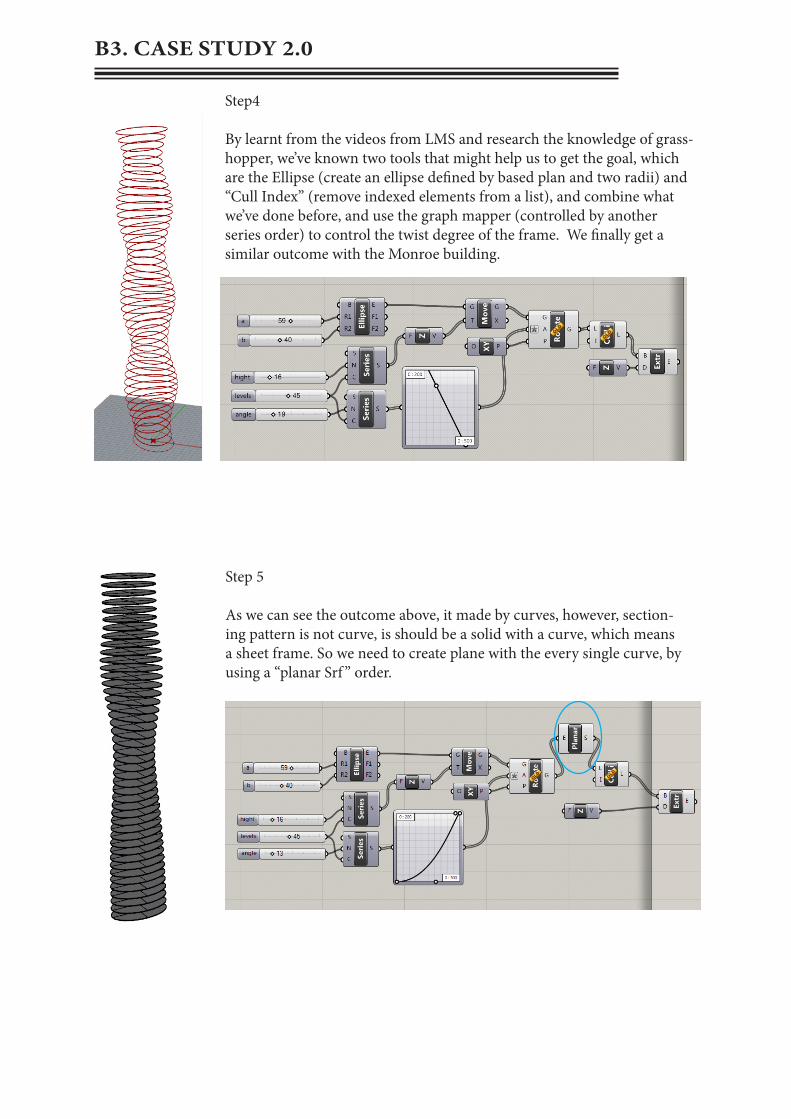
Step4 By learnt from the videos from LMS and research the knowledge of grass-hopper, we’ve known two tools that might help us to get the goal, which are the Ellipse (create an ellipse defined by based plan and two radii) and “Cull Index” (remove indexed elements from a list), and combine what we’ve done before, and use the graph mapper (controlled by another series order) to control the twist degree of the frame. We finally get a similar outcome with the Monroe building.
Step 5
As we can see the outcome above, it made by curves, however, section-ing pattern is not curve, is should be a solid with a curve, which means a sheet frame. So we need to create plane with the every single curve, by using a “planar Srf ” order.
B3. CASE STUDY 2.0
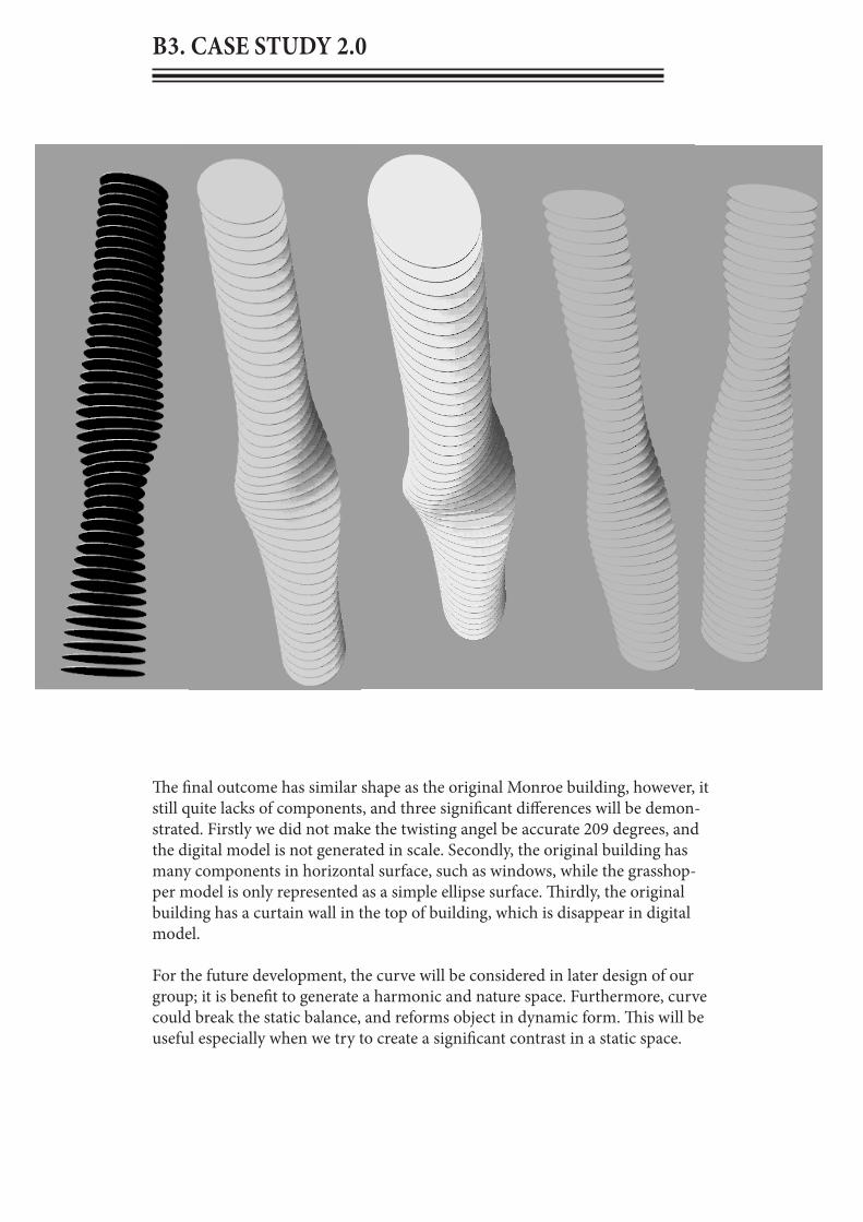
The final outcome has similar shape as the original Monroe building, however, it still quite lacks of components, and three significant differences will be demon-strated. Firstly we did not make the twisting angel be accurate 209 degrees, and the digital model is not generated in scale. Secondly, the original building has many components in horizontal surface, such as windows, while the grasshop-per model is only represented as a simple ellipse surface. Thirdly, the original building has a curtain wall in the top of building, which is disappear in digital model.
For the future development, the curve will be considered in later design of our group; it is benefit to generate a harmonic and nature space. Furthermore, curve could break the static balance, and reforms object in dynamic form. This will be useful especially when we try to create a significant contrast in a static space.

B4. TECHNIQUE: DEVELOPMENT
This is the matrix for case study 2.0; we were interested in looking at the different out-comes that we can make from the idea the building that we chose by using the new definition that we’ve created in the last phase. We’ve tried to observe the different out-comes with different angels, different number of the sectioning patterns. And also add something else in the original definition, which from the rotate curves part; we divide the rotate curves and then keep working on the divide curves to get different outcomes.

B4. TECHNIQUE: DEVELOPMENT

B 4. TECHNIQUE: DEVELOPMENT

B5. TECHNIQUE: PROTOTYPES
This is our first complete model, since our unclear concept and intention; we’ve changed the ideas for many times, so that we should behind others far away. For this model, we were focus on the effect of the shadow and the shape of the cave, which we want to give drivers a feel of change from irregular to regular who can represent the development of Wyndham city, and we also have considered the frame and the materialisation. We want to use plywood, since plywood is kind of lightweight and a light-tight material, which can make a sculpture that, looks not heavy, and can play with shadow with the space between the every two sectioning patterns. Another factor that we want to use plywood is that, we want to use it to represent nature, so we can endow the sculpture a organic mean.

B5. TECHNIQUE: PROTOTYPES
These diagrams are the connections between the elements and the how to connect to the ground. The connection type between the elements is an inlaid frame, which the vertical sectioning frames need a horizontal beam to inlay to them. Also there is another method could take for the connec-tion between the elements, which was shown on the physical model. It needs steel to across the sectioning patterns to fix the sectioning frame. The ground condition we consider to put a concrete footing as a base and a timber lay on the concrete footing as a bottom plate, and the sectioning frame could insert into the timber like the diagram shows above, and then we need to nail the sectioning and the bottom plate together to double reinforce it.

B6. TECHNIQUE PROPOSAL
A gateway is like a gate to somewhere, the role is just like a door to a house. Wyndham is a boom town, and this means it needs to attract more people’s vision to pay close attention to it. So that the proposal to design the gateway for Wyndham is to allow more people get know about Wyndham. Consider about that, the aim of our design proposal is try to create a sculpture or a land-mark building, which can reflect to Wyndham, since Wyndham has already developed and still keep developing, it has changed, from a county to become a modern city, it need to has something that can represent it, in other word, it need a landmark, just like Sydney has the Opera House and Melbourne has the federation square. They all can represent their city, and this is what Wynd-ham need, also what this project asks for.
Our group want to create a landmark architecture or a sculpture. Consider about process of the development of Wyndham, we want the create some-thing that can represent the change of Wyndham. We want use the change from irregular to regular to represent the change of Wyndham from a country to a modern city. So we tried to use the process of the change of an irregular geometrical form to a regular form. We also want to use a shelter form as our main form which can cover one of the high way roads, because we believe that if people can across the shelter they will get the most direct experience about the gateway (if our design can play the role successfully). Also the sectioning frame can also take some interesting effect such as light, shadow etc.

B 7. ALGORITHMIC SKETCHES
Image sampling: use the image sampler to control the points on the surface, this is worked by distinguishing the black and white colour.
Case study 2.0, study with an actual building, learn to use ellipse, series, graph mapper, rotate , and planar srf.

B 7. ALGORITHMIC SKETCHES
Evaluating fieldsLearn how to use the point charge to create a field due to a point charge, merge a collection of fields into one and compute the field line through a certain point.
This is one of our definitions of sectioning; this is our starting point for the major project.

B 8. LEARNING OBJECTIVES AND OUTCOMES
From the feedback of the mid semester presentation, we regretfully found that we were not on the right track, we were just think about that what we want to do, and what we think, but neglect the fact, which is what Wynd-ham need, even though we had also think about that, but that seems not correct way to think about, which means that might not suitable for Wyn-dham or not only suitable for Wyndham, because this is a proposal for Wyndham, if the idea could fit any other place, so it could not be a land-mark building. Our design was not relevant to our concept, while that’s because we didn’t have a specific concept to guide our thinking, so we that our work actually didn’t reflect anything. Also, there is another aspect that we were lack of the definition explored. Indeed, we can not only play with the definition, because that quite boring, and cannot show others what we’ve learnt. We all think the feedback is quite useful for our future develop. From the feedback, we’ve found something that can guide us, first of all, we need to consider the relationship with the site, which we have to know where is he Wyndham city, and we have to notices that it is not a cave and also not near a cave, so the cave idea could not work very well; secondly, we need to consider what we want to represent to people; thirdly, we are not necessary to be restricted with looking for an representation of Wyndham, we could also consider to design something that the people there are going to be proud of.

B 8. LEARNING OBJECTIVES AND OUTCOMES
By analysis the feedback that we’ve get from the mid semester presentation, we’ve rethinking about our intention. We were thinking to design something to contrast to the surrounding environments to give the users (drivers) a different experience when they across the gateway, since the site is quite a flat and static space, so we want to create something over the ground to against the flat space, in order to at-tract drivers’ view. We want them to experience a lightness change experience, and also motion experience.
This model below is our new idea which tried to catch our intention
Firstly, we were thinking a more dynamic form than the previous one which can contrast the static environment surrounding the site;Secondly, the density of the sectioning patterns is different, since the feeling will be different with different density, the more density the rhythm will be quicker. Thirdly, the curving shape can reflect to the motion, try to give the drivers a liquid feeling, since they are always move on the high way.Fourth, the different angle of the sectioning patterns will make different lightness to the road, since the sectioning pattern can stop or allow the light come through, and this can give people an experience with the light change, which is “light –dark-light”. It also can create some interesting shadows on the road and we will develop it fur-ther by finding the relevant with Wyndham.

B 8. LEARNING OBJECTIVES AND OUTCOMES
After the study in part B, I was having a further understanding of parametric design technique. I think the more you’ve know about the parametric design, the more you will know it’s powerful. I think the computation and parametric design is changing the architecture world, not because it is a new born technique, because it’s pow-erful compute ability, and that will make the design become easier and quicker. In addition, the parametric will take the modern architecture to a new realm, because the parametric architecture is totally different from the traditional architecture, it is a kind of new architecture that breaks the bondage of the traditional building code.
Indeed, the parametric design is quite a good thing, but it is also the hard subject to learn at the same time. During the study of the parametric design, I was usually felt dizzy, because the lines connection, the unknown orders, the clash things, lots of them. It is quite painful if we have some good idea but cannot work it out with the computer, and sometimes it might very complex. However, it is still a good subject to take; it has lots of advantages than the traditional design. For example, it is easy to make a model with fablab, because the parametric design can easily unroll a 3D model to a 2D model, and use the laser cutter to cut down with the different mate-rials, this will be easy to make a physical model to test, and compare the different outcomes with different materials.
I think I can do some simple manipulate and design using parametric modelling with the 8 weeks study. But I know I still have lots of knowledge to learn, and fortu-nately I still have a strong interest in it, and I will keep studying with it.

PART A CASE FOR INNOVATION
PART B DESIGN APPROACH
PART C PROJECT PROPOSAL
C 1. DESIGN CONCEPTC 2. TECTONIC ELEMENTS
C 3. FINAL MODELC 4. ALGORITHMIC SKETCHES
C 5. LEARNING OBJECTIIVES AND OUTCOMES
PART A CASE FOR INNOVATION
PART B DESIGN APPROACH


C 1.1 DESIGN CONCEPT
After the mid-semester presentation, we rethink how we want to go on with our design with the feedback from the crits jury in the presentation.
1. Our group still focus on the contrast idea, and we still want to use the tunnel form, since our concept is to create a brand landmark for Wyndham, we thought a tunnel form could allow driver go through it, and this might be better to provide the driver’s an experience, rather than create sculptures beside the road. In other word, we think the tunnel will give the drivers a directly visual experience.
2. We’ve changed the contrast factors, because our previous idea of the con-trast is not strong enough, everything set there will form a contrast with the land-scape, so we need push more on our design, make is has some specific mean to represent the contrast idea. We will use the idea of decomposition and re-composi-tion to from a contrast between different shapes, which means decompose a ge-ometric and use the same elements to compose a new geometric.
3. We’ve changed the effect of the light, because the sectioning structure is lack of the performance of the light than others. But that mot means we give up the light (shadow) performance, we only change our focus from the light to another aspect, the shadow effect will be still there, but it would not be our main intension.

C 1.1 DESIGN CONCEPT
Argument
I think a gateway project need to represent its site, because it will play the role as a door, there must have something different between inside and outside of the door. So our group want to make a contrast environment or experience in this gateway project. Based on this, our group concept was worked out, which is to create a brand landmark for Wyndham. We want to create an interesting driving experience, which people there could the project to identify themselves.
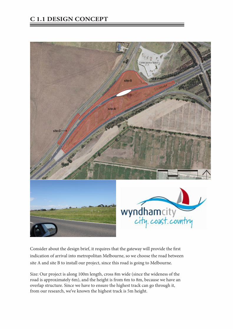
Consider about the design brief, it requires that the gateway will provide the first indication of arrival into metropolitan Melbourne, so we choose the road between site A and site B to install our project, since this road is going to Melbourne.
Size: Our project is along 100m length, cross 8m wide (since the wideness of the road is approximately 6m), and the height is from 6m to 8m, because we have an overlap structure. Since we have to ensure the highest track can go through it, from our research, we’ve known the highest track is 5m height.
C 1.1 DESIGN CONCEPT
C 1.1 DESIGN CONCEPT
Since the gateway project ask our design to provide an entry statement and arrival experience, and it will be viewed by the drivers who travelling at a high speed, and provide them the first sign of arrival into Melbourne. So it means that we have to design some-thing, which can provide the drivers a symbol that where they will arrive. We believe that our design will relevant and benefit for the freeway art project. Because it could reflect the change and development of Wyndham, and also can give drivers a feel of immer-sive with the tunnel form. Based on these, the effect of our design would be has quite experiential and memora-ble features.
In addition, compare with other tech-niques, sectioning has one conspicuous character, which is having a quite simple form. Consider about the site is a high-way, so we thought that the gateway project should not be a tangle some form, because that might disperse the drivers’ attention too much, and this might cause accidents with a high speed driving. And this is another reason that we choose sectioning, because sectioning could create a quite simple form. In this way, we can use a simple form to represent Wynd-ham. We thought that not only a dazzling from can attract people’s attention, but also can perform by a simple form. So we aim to create an interesting gateway, which can represent Wyndham by attach-ing the project brief.
Why our design for the gateway project.

Interesting Driveing Experience
Brand / Land-mark
For Wyndham
CONTRAST
Decomposition&
Recomposition
Geometric
Final Design
SectioningDensity
Individual dis-course topics
Change&
Development
Design 1(Unengaging)
C 1.2 DESIGN DIAGRAM

C 1.3 TECHNIQUE NODE DIAGRAM
set a basic curve in rhino
set a basic form in rhino
(polysurface)
extrude the curves
collect the curve that set in rhino
(Curve)
control the number of the
offset curves and the step size
decompose the brep (the extrude surface) into its component
(Explode)
set the direction of the extrude curves
split a surface with a bunch of curve
offsect the curve
selected polysur-face in rhino
(Brep)
solve the intersection events for the two breps (the extrude surface and the polysurface in rhino)
(Brep|Brep)

C 1.4 DEVELOPMENT
vs
As I mention above we focus on the process of the decomposition and composition, we start with making some simple geometric forms, and decompose them to single ele-ments, after that we compose them with a new order, and this will form a new geometry with the same elements. And this could demonstrate the process of the decomposition and composition, and it is able to form a contrast between the original form and the transformed form.

After lots of form test, we finally decide the diamond form (also could be described as prism form), because the diamond form is quite rigid, after the decompose and re-compose. We can get a relative soft form, so we do not only get a contrast between the initial form and the changed form, but also get a new idea about what kind of experience that we want to give the drivers. In other words, we can provide the drivers an experience of progression from a rigid form to a soft form.
Moreover, there is another reason that we choose the prism form, which is because of its multi-surface. Since Wyndham is a multi-culture city, it has an ethical diversity character, so the multi-surface can reflect on that. And this can help us to design the effect of the project.
C 1.4 DEVELOPMENT

C 1.4 DEVELOPMENT
Basic surface
Geometric patterns

set a basic surface in rhino
Divide a two-dimen-sional domain into equal seg-
ments on the surface
extract an isopara-metric subset of a sur-
face
Create a twisted box on a surface patch
set the grometric patternsin rhino
Solve oriented geometry bounding
boxes
Solve oriented geometry bounding
boxes
Morph an object into a twisted box
Morph an object into a twisted box
Dispatch the items in a list into two target
lists
Geometry
C 1.4 DEVELOPMENT

Rigid
Transit
Smooth
After we work out the pattern inside the tunnel, we go back the tunnel form, which we made after the mid-presentation. The reason that we still use this form is because this form is more dynamic with its streamline shape, which is compare to the static environment at the site. We divided the tunnel into three parts to perform the three different panel shapes, in order to show the transformation. We morph the rigid form, transit form and the smooth form onto the surfaces of the different part of the tunnel, and this is our basic form of the tunnel project.
C 1.4 DEVELOPMENT: PATTERN

set a basic curve in rhino
set a basic form in rhino (poly-
surface)
extrude the curves
collect the curve that set in rhino
(Curve)
control the number of the offsect
curves and the step size
decompose the brep (the extrude surface) into its component
(Explode)
set the direction of the
extrude curves
split a surface with a bunch of curve
offsect the curve
selected polysur-face in rhino
(Brep)
solve the intersection events for the two breps (the extrude surface and the polysurface in rhino)
(Brep|Brep)
technique node diagram
entrance
exit
When we’ve done the form of the project, we need to consider how to cut it in a sectioning form; we’ve used the Grasshopper technique (see page 65) of the Driftwood Pavilion to cut our structure into sectioning. The rigid form at the entrance and the soft form at the exit could provide a contrast, and people could image what happen inside the tunnel, as I mention before, we want to create a trans-form process from a sharp form to soft one, in order to give the driver an intense feeling at the beginning, and they will more and more relax and comfortable when they go through the tunnel. Finally, they will exit the tunnel with a quite relaxed mood.
C 1.4 DEVELOPMENT: SECTIONING
C 2 TECTONIC ELEMENTS
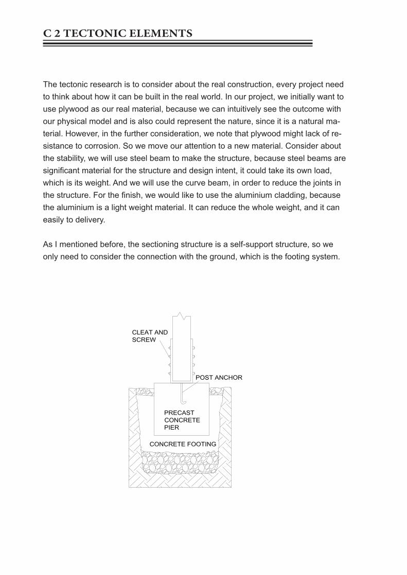
The tectonic research is to consider about the real construction, every project need to think about how it can be built in the real world. In our project, we initially want to use plywood as our real material, because we can intuitively see the outcome with our physical model and is also could represent the nature, since it is a natural ma-terial. However, in the further consideration, we note that plywood might lack of re-sistance to corrosion. So we move our attention to a new material. Consider about the stability, we will use steel beam to make the structure, because steel beams are significant material for the structure and design intent, it could take its own load, which is its weight. And we will use the curve beam, in order to reduce the joints in the structure. For the finish, we would like to use the aluminium cladding, because the aluminium is a light weight material. It can reduce the whole weight, and it can easily to delivery.
As I mentioned before, the sectioning structure is a self-support structure, so we only need to consider the connection with the ground, which is the footing system.

C 2 TECTONIC ELEMENTS: MATERIAL
Material choose, curve steel, alumini-um cladding, concrete footing.

C 3. FINAL MODEL

C 3.2 FINAL MODEL: FABRICATION PROCESS
Our project is quite simple in model making, as I mentioned before, sectioning always has a simple form, so it was very easy to make the physical model with fabrication, we just need to unroll the model in rhino (Grasshopper) and sent them to fablab to use the laser cutter to cut our sectioning patterns. The only thing we need to consider in the physical is what kind of material we will use and the joints. We’ve chose plywood, because plywood us used to repre-sent the steel in design, and is strong enough to hole the structure. In addition, we initially choose plywood as the real material of our project.Then we need to consider the joints, because sec-tioning is normally forming the self-support structure, so we just need to consider about the connection with the ground, which is the footing. We’ve used a thick cystosepiment to represent the ground; we stick each element in the cystosepiment. In this process we need to determine the distance between two ele-ments.
C 3.FINAL MODEL
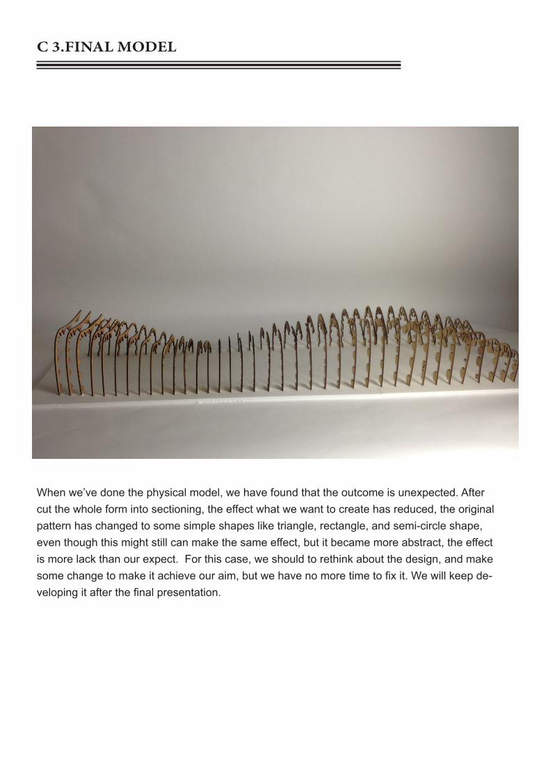
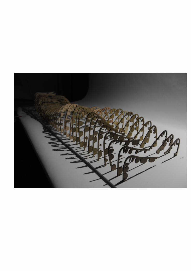
When we’ve done the physical model, we have found that the outcome is unexpected. After cut the whole form into sectioning, the effect what we want to create has reduced, the original pattern has changed to some simple shapes like triangle, rectangle, and semi-circle shape, even though this might still can make the same effect, but it became more abstract, the effect is more lack than our expect. For this case, we should to rethink about the design, and make some change to make it achieve our aim, but we have no more time to fix it. We will keep de-veloping it after the final presentation.

C 3.FINAL MODEL: PHOTOS OF THE MODEL


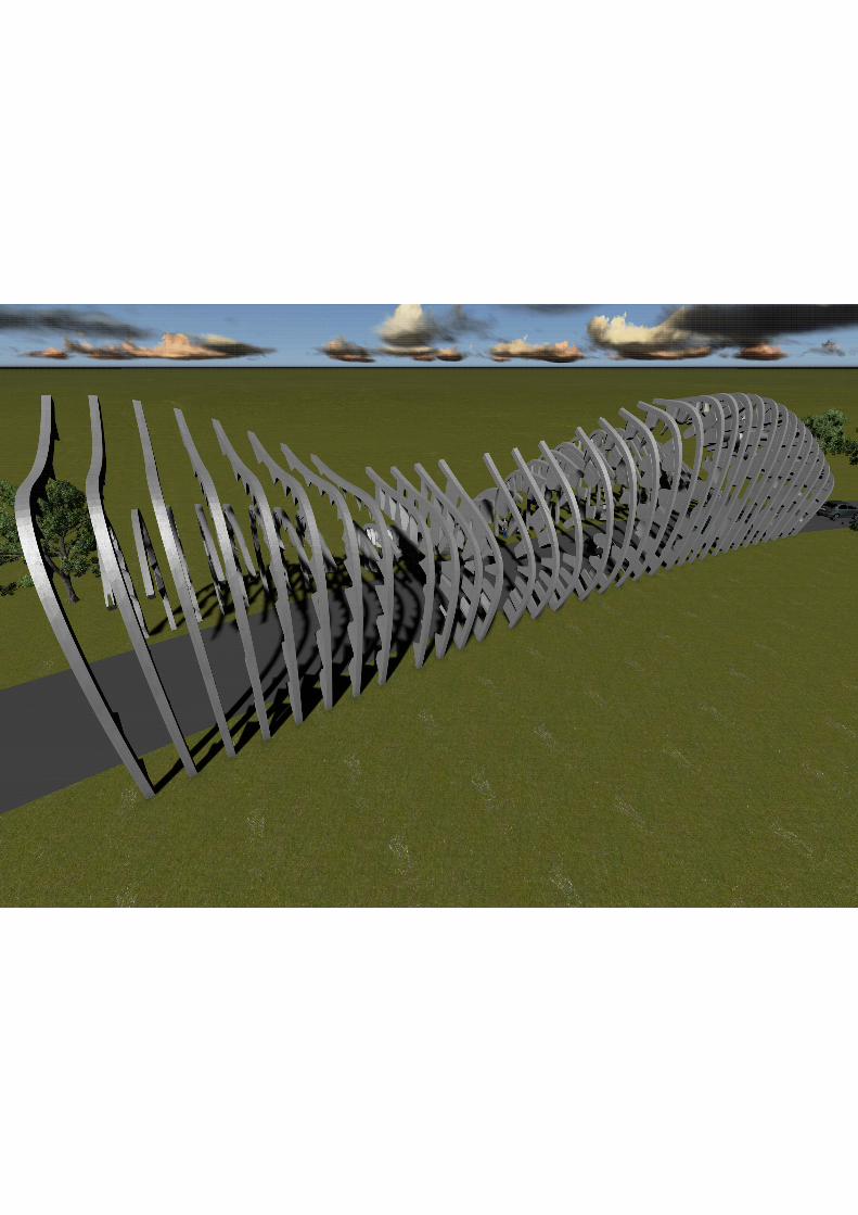
Structure

Site plan


C 4. ALGORITHMIC SKETCHES

C 5. LEARNING OBJECTIVES AND OUTCOMES
First of all, I was really appreciate to our tutor Zak and Michael, during the study of this semester I’ve learnt lots of knowledge from them, they always guide us in the right track, while we have some confusions with our design, like the way of thinking, the direction of our design and the EOI outcomes and so on. More important, they not only taught us the technology of parametric design (Grass-hopper), but also taught us how to make a design process, I’ve learnt how to design a project, the way of thinking, like what the project ask for us, what we want to create for the site (intention). I think this should be the most important knowledge in this semester.
Also I would like to thank my group members Zhijie and Tenghui. Since this project is a group work, so the cooperative skill is another important thing I’ve learnt in this studio. Since design is a multi-disciplinary collaboration, for one aspect we can share and discuss our ideas; for another aspect, each member in the group can do what he good at. I think this is also a basic ability in the future study and job for architect.
During the study of this semester, I’ve learnt lots of knowledge about parametric architecture. Parametric modelling is not a new subject for me, since I’ve seen some parametric architecture before, like the Galaxy SOHO in Beijing. When I was firstly saw the Galaxy SOHO, I was so amazing with it, because it quite different from the traditional architecture, and I didn’t know it is a parametric architecture, to be honestly, I have no any idea what is parametric, I was just interested in a new type of architecture. After this studio’s study, I’ve a more deep acknowledge with the parametric architecture.
Different outcomes.
Parametric architecture is a new type of architecture, the building type and out-comes are quite different from the traditional architecture. The outcome could be more flexible. Compare to the traditional architecture, the parametric architecture can represent the modern architecture preferable. Reflect to my argument in the innovation ‘architecture as a discourse of art’, parametric architecture could explain this argument very well.

Efficiency.
Parametric architecture could shorten the time of the construction. The tradition-al architecture has a big problem with the design and the construction, because sometimes the design could not be build in the real world, so the communication between constructor and the architect is always take too long time. Parametric architecture has solved this problem, because the it easily to test the digital in real life with the digital fabrication, and it also can test the materials and the structure. It is quite convenient and efficiency for the architecture. This could save lots of time of the construction process.
Technology.
Grasshopper is quite a powerful software, during the study with it, I’ve found it is really a good software for parametric design, design with Grasshopper could make it much easier. And it is also quite a difficult one to use. After this semester’s study, I’ve have the basic skill of using the software, but not good at it. I think I can do some simple design, but to be honestly, I don’t think I can do a project like the pro-ject on this studio by myself. So I still need to learn more about Grasshopper, and I will keep studying with it.
Other skill.
I’ve also learnt some other skills, while they all relate to architecture, such as the, model making skill, and other softwares like render with rhino, how to form a journal layout with Indesign, and how to use Lumion to make a video to help us to show the design in the real life.
To surmise, I’ve learnt quite a lot knowledge during this short period in this studio, even though I’ve had lots of days without a good sleep, even though our design were not good enough by comparing to others, I still feel very satisfied with this studio, because I’ve learnt the knowledge, I’ve already get my pay back for my pay out. I’ve know how to do an design, how to organize a design process, and how to use Grasshopper, and I will keep learning all of these, keep improving my skills, in order to achieve my architecture dream.
C 5. LEARNING OBJECTIVES AND OUTCOMES
FEEDBACK RESPOND &FURTHER DEVELOPMENT
After the final presentation, we’ve got lots of information from the tutors and the gusts, I’ve classify them into two parts: one is the comment of our project; another is about the sugges-tions for our group.
For our project:
Basic on the feedback of the footing, we need to make the footing much deeper into the ground, if not or there are other limitations some reinforcement to tie it down. Otherwise, it will tip over.
For the sectioning form, Michael asked us to consider about the joint of the sectioning struc-ture between vertical and horizontal. For this case, as I mention before, based on our re-search, we could use the curved steel, which means for the sectioning structure, it is a whole structure rather than two parts, and the reason we do this is to reduce the joints on the pro-ject.
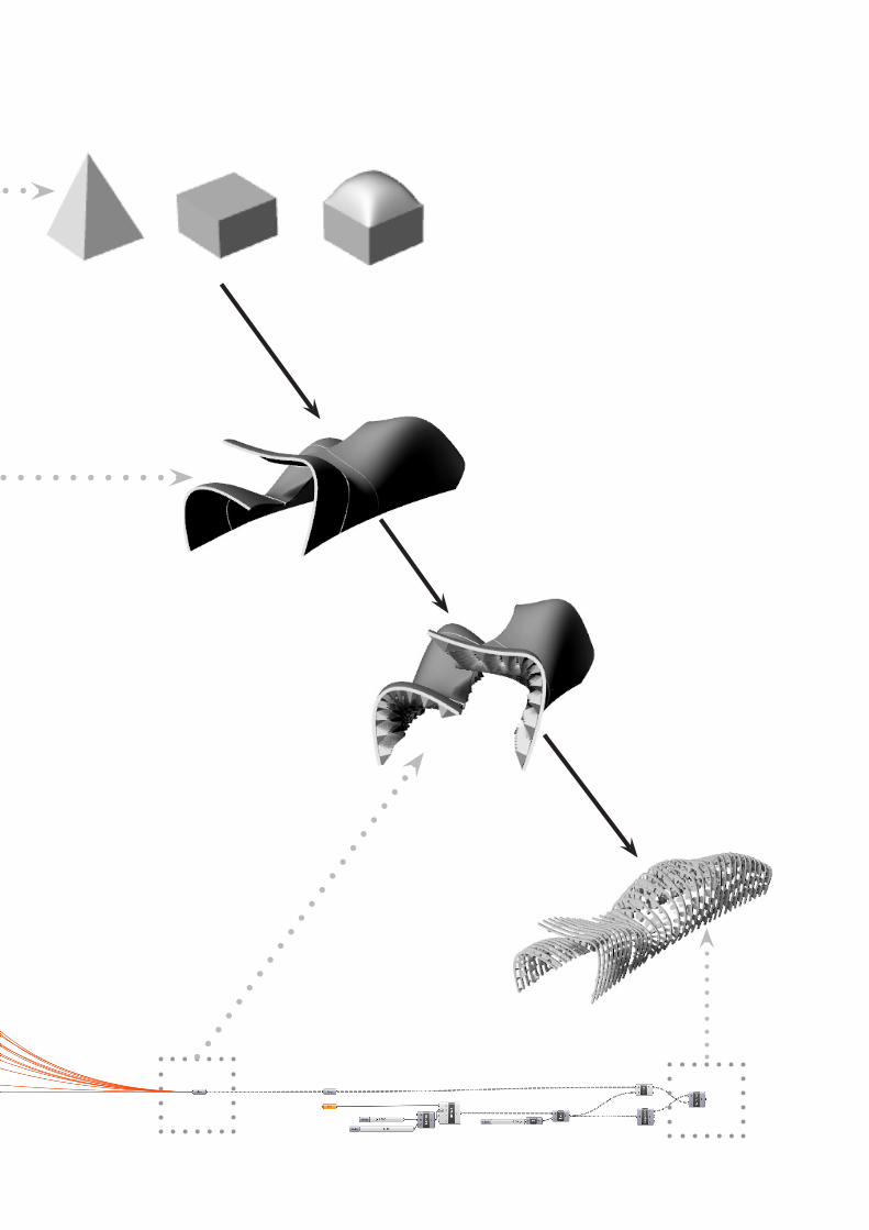
For the basic form, some guests confuse about our final digital model and the sectioning form digital. That’s because our group topic is sectioning, so the surface digital model has shown the effect of the project, when we were doing the design of the project, we’ve only think about what we want to create, how to make our design attach our concept and intention without related to the sectioning concept. After we’ve worked the final outcome, use the script that provide on LMS to cut the form into sectioning form. However, it seems we have a misunder-standing of the topic of sectioning; we were ask to design a sectioning project, not just make a geometric form and cut it into sectioning form. And this is the main reason that our final out-come is unexpected. So we need to rethink about the characteristics of sectioning, and think how to use these to form our project.
Suggestion for us:
From the feedback of the final presentation, we’ve also got some suggestions about our cog-nize for design:
-We need take more ownership of our design process, our design is to do what we think easy, and get a good direction, not just do what the tutor want us to do.-We need become engage and excited about what doing, even though we always has strug-gle within the process, because the struggle is usually a good thing in design, it could help us to generate interesting outcome.-Do not pressure ourselves about one idea for too long, design need lateral thinking, which means we need to open our mind, we need to learn how to detach ourselves away from a process when we’ve no idea about it, and do the critical analysis of what we’ve done.
FEEDBACK RESPOND

FURTHER DEVELOPMENT
From the feedback, we’ve know what is our problem, we was too struggle within the process. We have a good idea about the contrast, which is the decomposition and re-composition, but we need to detach ourselves away from the last process, to think something new. Based on the tutor’s suggestion, we think we could use the prism form to show the process from decomposition to re-composition. We’ve drawn the basic prism form in rhino and decompose it to eight single triangle pat-terns, combine them with a new order to form a new form. We tried to cut it to a sectioning form with Grasshopper, but we can only cut the original geometric, I think that unfolded elements might not be able to cut; so we need to develop the form. Even though we did not work a new project, we still found something interesting. From the sectioning form that we cut, we’ve found that the view could change with different distance, and different density. So we think this is quite an interesting di-rection that we can develop. We’ve all known we’ve restrict by the tunnel form from the beginning, like the tutor’s suggestion, we need to detach ourselves away from the previous process. So we want to give up the tunnel idea, we want move our attention to a sculpture, use the sectioning technique try to explain these geometric, and develop it.

FURTHER DEVELOPMENT: PRECEDENT
PolymorphicThe polymorphic YouthColumbia University, Columbia 2010source: http://www.polymorphicyouth.com/
From the Polymorphic Youth, I just want show our new direction, they will be some geometric set on the ground, and they will form a process of decomposition and re-composition.

Text source:
Institute for Computational Design 2010 ICD Research Project http://icd.uni-stutt-gart.de/?p=4458 viewed 26th March
Kalay, Yehuda E.(2004). Architecture’s New Media: Principles, Theories, and Meth-ods of Computer-Aided Design (Cambridge, MA: MIT Press) pp.5-25
Kieran, Stephen, and James Timberlake (2004). Refabricating Architecture: How Manufacturing Methodologies are Poised to Transform Building Construction (New York: McGraw-Hill). pp. 12, 15, 23.
Williams, Richard (2005). ‘Architecture and Visual Culture’, in Exploring Visual Culture: Definitions, Concepts, Contexts, ed. By Matthew Rampley (Edinburgh: Edinburgh University Press), pp. 102-116
Woodbury, Robert (2010). Elements of Parametric Design (London: Routledge) pp.7-47
Web source : http://uk.linkedin.com/in/rolandorodriguezleal viewed 3ed April
web source: http://amassingdesign.blogspot.com.au/2010/04/cave-restaurant-koi-chi-takada.htmlweb source: http://www.ydzsw.com/shownews.asp?id=10562 viewed 8th Mayweb source: http://www.yatzer.com/BANQ-restaurant-by-Office-dA
REFERENCE
Image source:
source: http://www10.aeccafe.com/blogs/arch-showcase/files/2013/01/CZA_ PA007_9374.jpgsource: http://www.yatzer.com/BANQ-restaurant-by-Office-dAsource: http://amassingdesign.blogspot.com.au/2010/04/cave-restaurant-koi chi-takada.htmlsource: http://www.ydzsw.com/shownews.asp?id=10562source: http://twistedsifter.com/2012/07/marilyn-monroe-absolute-tow ers-by-mad-architects-mississauga/source: http://newimg.globalmarket.com/PicLib/825/625825/ prod/42_1323065567398_l.jpgsource: http://www.mbarconline.com/solar_curved_steel_single.htmlsource: http://www.polymorphicyouth.com/