Embed Size (px)
Citation preview
CL
MLGC
CNA
CB
CV/MVG
CXW
CXS
CXT
MX
MXU
MXS
MXQ
MXF
MXW
MXP
MG
MGP
MGQ
MGG
MGC
MGF
CY1
MY1
***
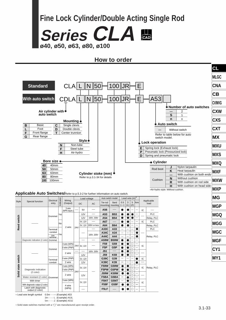
With auto switch
CLA
CDLA
L
L
N E
N
50
50
100
100
JR
EJR A53
Air cylinder with auto switch
MountingC D T
Single clevisDouble clevis
Center trunnion
B L F G
BasicFoot
Front flangeRear flange
StyleN F H
Non-lubeSteel tubeAir-hydro
Bore size40506380100
40mm50mm63mm80mm
100mm
Cylinder stoke (mm)Refer to p.3.1-34 for details
Number of auto switches—Sn
21n
Auto switch
Refer to table below for autoswitch model.
— Without switch
Lock operation
E P D
Spring lock (Exhaust lock)Pneumatic lock (Pressurized lock)Spring and pneumatic lock
*Air-hydro style: Without cushion.
Cylinder
Rod boot
Cushion
JK—NRH
Nylon tarpaulinHeat tarpaulinWith cushion on both endsWithout cushionWith cushion on rod sideWith cushion on head side
Style Special function
With timer
With diagnostic output (2 color)Latch with diagnostic
output (2 color)
Applicable load
Electrical entry Tie-rod
mountingBand
mountingIndi
cato
r
DC AC
Auto switch model Lead wire (m)*
0.5(—)
3(L)
5(Z)
None
Load voltage
Ree
d s
wit
chS
olid
sta
te s
wit
ch
Grommet
Terminal conduit
DINterminal
Grommet
Grommet
Grommet
Terminalconduit
Yes
No
Yes
Yes
3 wire(NPN equiv.)
2 wire 24V
24V
24V
2 wire
2 wire
2 wire
3 wire (PNP)
3 wire (PNP)
3 wire (NPN)
3 wire (PNP)
3 wire (NPN)
3 wire (NPN)
4 wire(NPN)
5V
12V
5V, 12V
5V, 12V
5V, 12V
12V
5V, 12V
A56
A53A54A67A64
A33CA34CA44CA59WF59F5PJ51J59
G39CK39CF59WF5PWJ59WF5BAF5NTF59F
F5LF
B53B54
B64A33A34A44
B59WG59G5P
K59G39K39
G59WG5PWK59WG5BAG5NTG59F
IC
IC
IC
IC
IC
IC
PLC
PLC
PLC
Relay, PLC
Relay, PLC
Relay, PLC
Relay, PLC
100V, 200V
200V or less
100V, 200V
100V, 200V
Applicable Auto Switches/Refer to p.5.3-2 for further information on auto switch.
12V
12V
12V
5V, 12V
5V, 12V
Wiring (Output)
* Lead wire length symbol 0.5m······— (Example) A533m·········L (Example) A53L5m·········Z (Example) A53Z
Diagnostic indication (2 color)
Diagnostic indication(2 color)
Water resistant (2 color)
Q
Q
Q
Q
Q
Q
Q
Q
Q
Q
Q
Q
Q
Q
Q
qqqq
qqq
q
q
* Solid state switches marked with a “q” are manufactured upon receipt order.
Standard
How to order
P
P
P
P
P
P
P
PP
3.1-33
Fine Lock Cylinder/Double Acting Single Rod
Series CLAø40, ø50, ø63, ø80, ø100
CL series(569-632) 99.2.20 5:03 PM Page 33
**
CLAlNCLAlH
Double acting
Style
Specifications
Series Style Action
40, 50, 63, 80, 100
Bore size (mm) Lock style
Non-lube style
Air-hydro style
Spring lock, Pneumatic lock,
Spring and pneumatic lock
Style
Fluid
Proof pressure
Max. operating pressure
Min. operating pressure
Piston speed
Ambient and fluid temperature
Cushion
Thread tolerance
Stroke length tolerance
Mounting
1.5MPa
1.0MPa
JIS class 2
to 250: , 251 to 1000: , 1001 to 1500:
Basic, Axial direction foot, Front flange, Rear flange,
Single clevis, Double clevis, Center trunnion
Lock Specifications
Auto Switch Mounting Bracket Part No.
Lock
Auto switch modelBore size
40 50 63 80 100
BT-04
BD1-04M
BA-04
BA3-040
BT-04
BD1-05M
BA-05
BA3-050
BT-06
BD1-06M
BA-06
BA3-063
BT-08
BD1-08M
BA-08
BA3-080
BT-08
BD1-10M
BA-10
BA3-100
D-A5/A6/A59WD-F5l/J5l/F5Wl/J59WD-F5NT, F5BA, F59F
D-B5/B6/B59WD-G5l/K59/G5lW/K59WD-G5BA/G59F/G5NTL
D-A3/A44/G39/K39
D-A3lC/A44C/G39C/K39C
Rod Boot Material
Minimum Strokes for Auto Switch Mounting
Refer to p.1.9-4 because it is same as air cylinder CDA1 series (Standard/Double acting: Single Rod) style.
Symbol
JK
Material
Nylon tarpaulin
Heat resistant tarpaulin
Max. ambient temp.
60¡C
110¡C*
Spring lock (Exhaust lock)
Spring/ pneumatic lock
Pneumatic lock(Pressurized lock)
Lock release pressure (MPa)
Lock starting pressure (MPa)
Max. operating pressure (MPa)
Lock direction
0.3 or more
0.25 or less
0.5
Both directions
0.1 or more
0.05 or more
*Constraints associated with the allowable kinetic energy are imposed on the speeds at which the piston can be locked.
Note) Intermediate stroke except stroke mentioned above is also available. Contact SMC.
* Maximum ambient temperature for the rod boot itself.
Accessories
* Only the Double knuckle and the double clevis are provided as standard equipment.
Rod end nut (Standard equipment), Single knuckle joint, Double knuckle joint, Knuckle pin*, Clevis pin*, Rod boot
+1.00
+1.40
+1.80
Non-lube
Air
Air-hydro
Turbine oil (Lock portion is air)
0.08MPa 0.2MPa
Air cushion
Without auto switch: –10¡C to 70¡CWith auto switch: –10¡C to 60¡C
None
(No freezing)
Standard StrokeBore size (mm) Standard stroke (mm) Max. stroke
25, 50, 75, 100, 125, 150, 175, 200, 250, 300, 350, 400, 450, 500
25, 50, 75, 100, 125, 150, 175, 200, 250, 300, 350, 400, 450, 500, 600
25, 50, 75, 100, 125, 150, 175, 200, 250, 300, 350, 400, 450, 500, 600, 700
25, 50, 75, 100, 125, 150, 175, 200, 250, 300, 350, 400, 450, 500, 600, 700
800
1200
1400
1500
40
50, 63
80
100
Mounting Bracket Part No.Bore size
(mm)
Foot*
40
CA1-L04
CA1-F04
CA1-C04
CA1-D04
50
CA1-L05
CA1-F05
CA1-C05
CA1-D05
63
CA1-L06
CA1-F06
CA1-C06
CA1-D06
80
CA1-L08
CA1-F08
CA1-C08
CA1-D08
100
CA1-L10
CA1-F10
CA1-C10
CA1-D10
* When ordering foot brackets, 2pcs. should be ordered for each cylinder.** Clevis pin, plain washer and cotter pin are packed
with the double clevis style.* Mounting brackets are provided with D-A3lC, A44C, G39C, and K39C. When ordering, indicate as described below, in accordance with the cylinder size.
Example) ø40—D-A3lC-4, ø50—D-A3lC-5, ø63—D-A3lC-6, ø80—D-A3lC-8, ø100—D-A3lC-10To order the mounting brackets separately, use the part number shown above.
Flange
Single clevis
Double clevis**
50 to 500mm/s* 15 to 300mm/s*
Provided with a compact locking mechanism, it is suitable for intermediate stops, for emergency stops, and for drop prevention.
Recommended Pneumatic Circuit/Caution on HandlingCaution
Refer to p.3.1-2 to 3.1-5 for details of CLA series specifications mentioned above.
3.1-34
Series CLA
CL series(569-632) 99.2.20 5:03 PM Page 34
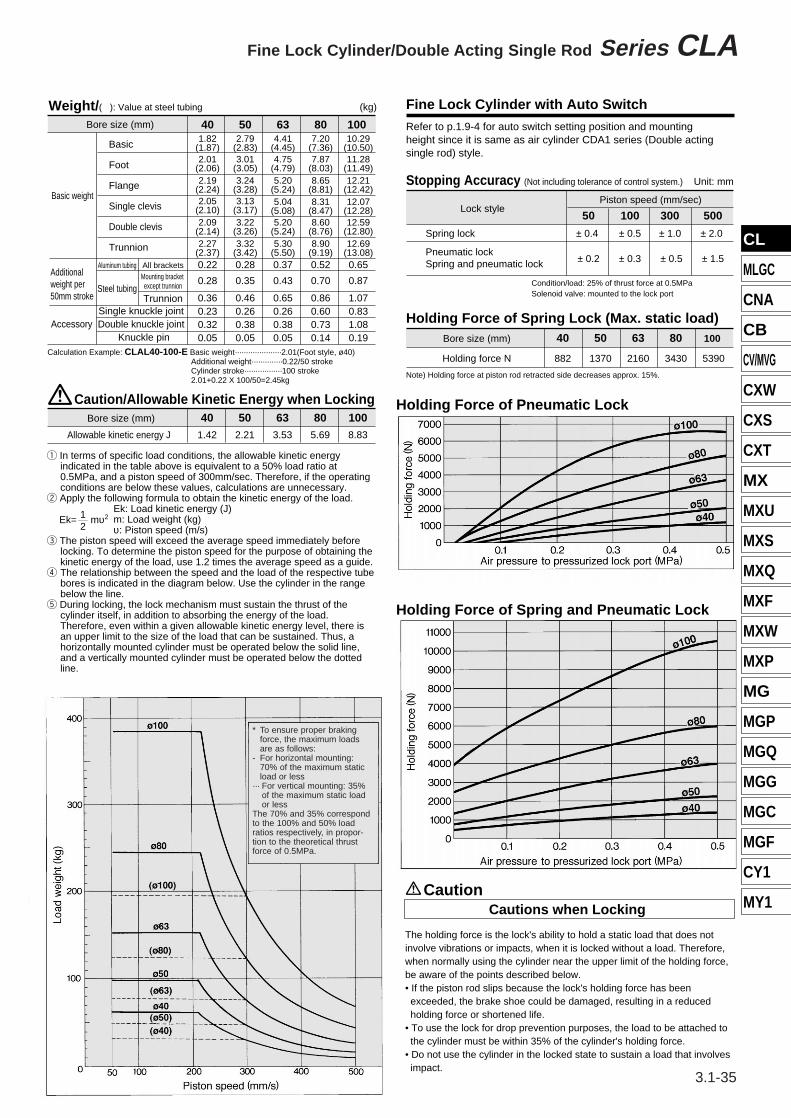
Weight/( ): Value at steel tubing Fine Lock Cylinder with Auto Switch
Stopping Accuracy (Not including tolerance of control system.)
Caution/Allowable Kinetic Energy when Locking
Bore size (mm)
Basic
Foot
Flange
Single clevis
Double clevis
Trunnion
Bore size (mm) 401.42
502.21
633.53
805.69
1008.83Allowable kinetic energy J
Basic weight
Aluminum tubing
Single knuckle jointDouble knuckle joint
Knuckle pin
Steel tubing
All bracketsMounting bracket except trunnion
Trunnion
Accessory
Additional weight per 50mm stroke
401.82
(1.87)2.01
(2.06)2.19
(2.24)2.05
(2.10)2.09
(2.14)2.27
(2.37)0.22
0.28
0.360.230.320.05
502.79
(2.83)3.01
(3.05)3.24
(3.28)3.13
(3.17)3.22
(3.26)3.32
(3.42)0.28
0.35
0.460.260.380.05
634.41
(4.45)4.75
(4.79)5.20
(5.24)5.04
(5.08)5.20
(5.24)5.30
(5.50)0.37
0.43
0.650.260.380.05
807.20
(7.36)7.87
(8.03)8.65
(8.81)8.31
(8.47)8.60
(8.76)8.90
(9.19)0.52
0.70
0.860.600.730.14
100 10.29
(10.50)11.28
(11.49)12.21
(12.42)12.07
(12.28)12.59
(12.80)12.69
(13.08)0.65
0.87
1.070.831.080.19
50
± 0.4
± 0.2
100
± 0.5
± 0.3
300
± 1.0
± 0.5
500
± 2.0
± 1.5
Lock style
Spring lock
Piston speed (mm/sec)
Calculation Example: CLAL40-100-E Basic weight·····················2.01(Foot style, ø40)Additional weight··············0.22/50 strokeCylinder stroke·················100 stroke2.01+0.22 X 100/50=2.45kg
(kg)
Unit: mm
Condition/load: 25% of thrust force at 0.5MPaSolenoid valve: mounted to the lock port
Holding Force of Spring Lock (Max. static load)40
882
50
1370
63
2160
80
3430
100
5390
Bore size (mm)
Holding force N
Note) Holding force at piston rod retracted side decreases approx. 15%.
Refer to p.1.9-4 for auto switch setting position and mounting height since it is same as air cylinder CDA1 series (Double acting single rod) style.
q In terms of specific load conditions, the allowable kinetic energy indicated in the table above is equivalent to a 50% load ratio at 0.5MPa, and a piston speed of 300mm/sec. Therefore, if the operating conditions are below these values, calculations are unnecessary.
w Apply the following formula to obtain the kinetic energy of the load.Ek: Load kinetic energy (J) m: Load weight (kg)υ: Piston speed (m/s)
e The piston speed will exceed the average speed immediately before locking. To determine the piston speed for the purpose of obtaining the kinetic energy of the load, use 1.2 times the average speed as a guide.
r The relationship between the speed and the load of the respective tube bores is indicated in the diagram below. Use the cylinder in the range below the line.
t During locking, the lock mechanism must sustain the thrust of the cylinder itself, in addition to absorbing the energy of the load. Therefore, even within a given allowable kinetic energy level, there is an upper limit to the size of the load that can be sustained. Thus, a horizontally mounted cylinder must be operated below the solid line, and a vertically mounted cylinder must be operated below the dotted line.
12
Ek= mυ2
Cautions when LockingCaution
Holding Force of Spring and Pneumatic Lock
Holding Force of Pneumatic Lock
The holding force is the lock's ability to hold a static load that does not involve vibrations or impacts, when it is locked without a load. Therefore, when normally using the cylinder near the upper limit of the holding force, be aware of the points described below.• If the piston rod slips because the lock's holding force has been exceeded, the brake shoe could be damaged, resulting in a reduced holding force or shortened life.
• To use the lock for drop prevention purposes, the load to be attached to the cylinder must be within 35% of the cylinder's holding force.
• Do not use the cylinder in the locked state to sustain a load that involves impact.
Pneumatic lockSpring and pneumatic lock
CL
MLGC
CNA
CB
CV/MVG
CXW
CXS
CXT
MX
MXU
MXS
MXQ
MXF
MXW
MXP
MG
MGP
MGQ
MGG
MGC
MGF
CY1
MY1
∗∗
3.1-35
Fine Lock Cylinder/Double Acting Single Rod Series CLA
∗ To ensure proper brakingforce, the maximum loadsare as follows:
- For horizontal mounting:70% of the maximum staticload or less
··· For vertical mounting: 35%of the maximum static loador less
The 70% and 35% correspondto the 100% and 50% loadratios respectively, in propor-tion to the theoretical thrustforce of 0.5MPa.
CL series(569-632) 3/10/99 3:36 PM Page 35
∗∗
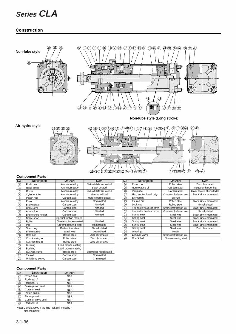
Component Parts
Component Parts
MaterialDescriptionRod coverHead coverCoverCylinder tubePiston rodPistonBrake pistonBrake armArm holderBrake shoe holderBrake shoeRollerPinSnap ringBrake springRetainerCushion ring ACushion ring BBushingBushingCushion valveTie rodUnit fixing tie rod
Aluminum alloyAluminum alloyAluminum alloyAluminum alloyCarbon steel
Aluminum alloyCarbon steelCarbon steelCarbon steelCarbon steel
Special friction materialChrome molybdenum steelChrome bearing steel
Carbon tool steelSteel wire
Rolled steelRolled steelRolled steel
Lead bronze castingLead bronze casting
Rolled steelCarbon steelCarbon steel
Black coated after hard anodizedBlack coated
Black coated after hard anodizedHard anodized
Hard chrome platedChromated
NitridedNitridedNitridedNitrided
NitridedHeat treatedNickel platedDacrodized
Zinc chromatedZinc chromatedZinc chromated
Electroless nickel platedChromatedChromated
Note
MaterialNo. DescriptionPiston sealRod seal ARod seal BBrake piston sealCushion sealPiston gasketTube gasketCushion valve sealRod seal C
NBRNBRNBRNBRNBRNBRNBRNBRNBR
MaterialNo. DescriptionPiston nutNon rotating pinPin guideHex. socket head pulgElememntTie rod nutLock nutHex. socket head cap screwHex. socket head cap screwSpring seatSpring seatSpring seatSpring seatSpring seatWearingExhaust valveCheck ball
Rolled steelCarbon steelCarbon steel
Chrome molybdenum steelBronze
Rolled steelRolled steel
Chrome molybdenum steelChrome molybdenum steel
Steel wireSteel wireSteel wireSteel wireSteel wire
ResinChrome molybdenum steelChrome bearing steel
Zinc chromatedInduction hardening
Black coated after nitridedBlack zinc chromated
Black zinc chromatedNickel plated
Black zinc chromatedNickel plated
Black zinc chromatedBlack zinc chromatedBlack zinc chromatedBlack zinc chromated
Zinc chromated
Note
Note) Contact SMC if the fine lock unit must be disassembled.
$1 $2 $3 $4 $5 $6 $7 $8 $9
@4 @5 @6 @7 @8 @9 #0 #1 #2 #3 #4 #5 #6 #7 #8 #9 $0
No.q w e r t y u i o !0 !1 !2 !3 !4 !5 !6 !7 !8 !9 @0 @1 @2 @3
Non-lube style
Air-hydro style
Construction
3.1-36
Series CLA
CL series(569-632) 3/10/99 3:36 PM Page 36
CL
MLGC
CNA
CB
CV/MVG
CXW
CXS
CXT
MX
MXU
MXS
MXQ
MXF
MXW
MXP
MG
MGP
MGQ
MGG
MGC
MGF
CY1
MY1
∗∗
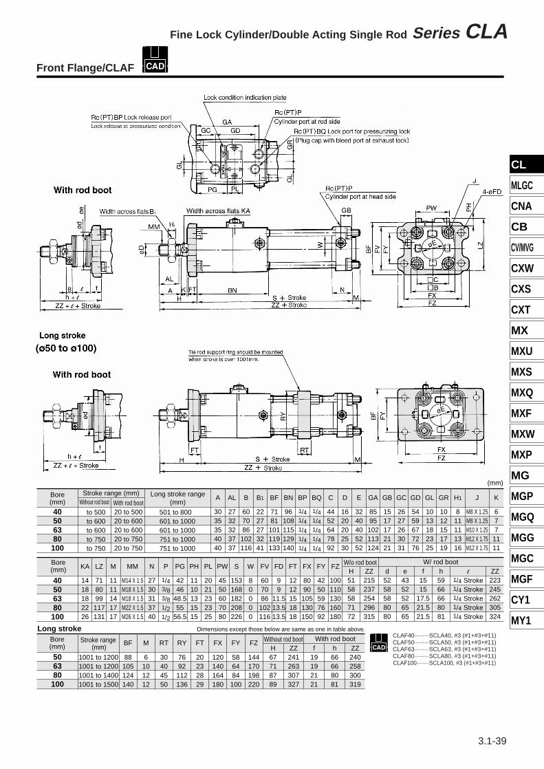
Bore(mm)
Stroke range (mm)Without rod boot
to 500to 600to 600to 750to 750
With rod boot20 to 50020 to 60020 to 60020 to 75020 to 750
A
3035354040
AL
2732323737
B
607086
102116
B1
2227273241
BN
96108115129140
BP
1/41/41/41/41/4
BQ
1/41/41/41/41/4
C
4452647892
D
1620202530
E
3240405252
F
1010101414
GA
8595102113124
GB
1517172121
GC
2627263031
GD
5459677276
GL
1013182325
GR
1012151719
H1
811111316
J
M8 X 1.25M8 X 1.25M10 X 1.25M12 X 1.75M12 X 1.75
40506380100
Bore(mm)
Without rod bootH5158587172
ZZ215237254296315
With rod boote4352526565
f11.211.211.212.514
l
1/4 Stroke1/4 Stroke1/4 Stroke1/4 Stroke1/4 Stroke
ZZ223245262305324
h5966668081
K
677
1111
KA
1418182226
LZ
718099
117131
M
1111141717
N
2730313740
P
1/43/83/81/21/2
PG
4246
48.555
56.5
PH
1110131515
PL
2021232325
PW
4550607080
S
153168182208226
W
80000
MM
M14 X 1.5M18 X 1.5M18 X 1.5M22 X 1.5M26 X 1.5
40506380100
(mm)
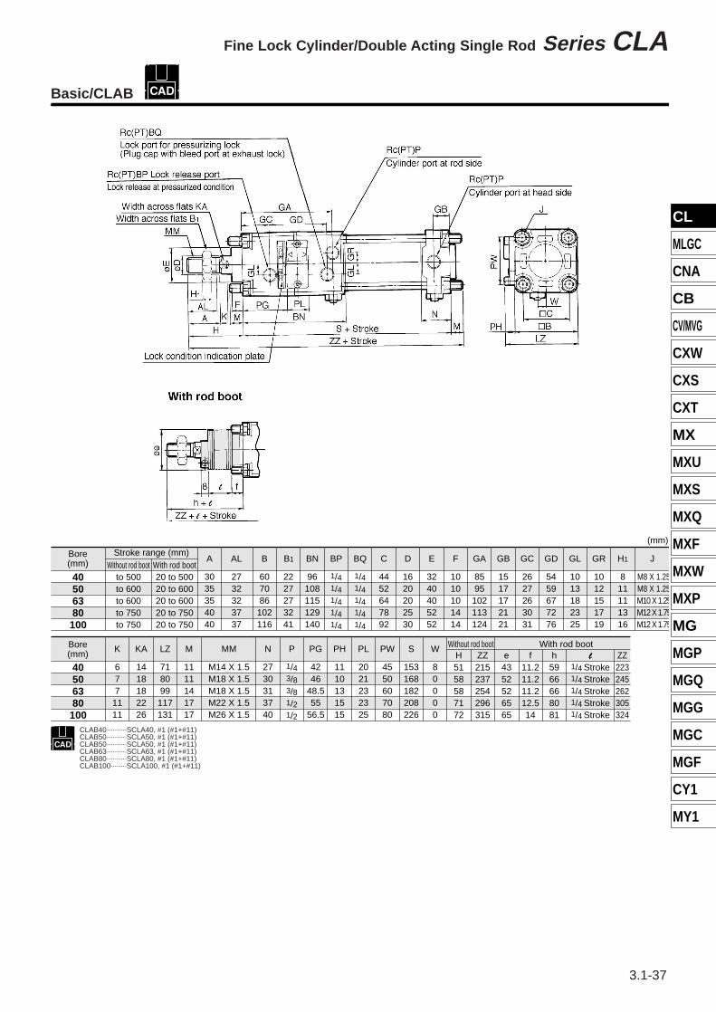
Basic/CLAB
CLAB40··········SCLA40, #1 (#1+#11)CLAB50··········SCLA50, #1 (#1+#11)CLAB50··········SCLA50, #1 (#1+#11)CLAB63··········SCLA63, #1 (#1+#11)CLAB80··········SCLA80, #1 (#1+#11)CLAB100········SCLA100, #1 (#1+#11)
l
3.1-37
Fine Lock Cylinder/Double Acting Single Rod Series CLA
CL series(569-632) 3/5/99 11:54 AM Page 37
∗∗
Stroke range (mm)
to 500to 600to 600to 750to 750
With rod boot20 to 50020 to 60020 to 60020 to 75020 to 750
GR
1012151719
GL
1013182325
GD
5459677276
GC
2627263031
GB
1517172121
GA
8595102113124
F
1010101414
E
3240405252
D
1620202530
C
4452647892
BQ
1/41/41/41/41/4
BP
1/41/41/41/41/4
BN
96108115129140
B1
2227273241
B
607086102116
AL
2732323737
A
3035354040
40506380100
Bore(mm)
Bore(mm)
H1
811111316
40506380100
Bore(mm) l
1/4 Stroke1/4 Stroke1/4 Stroke1/4 Stroke1/4 Stroke
h5966668081
f11.211.211.212.514.0
e4352526565
ZZ244266290339358
H5158587172
ZZ252274298348367
Y
1313161617
40506380100
Bore(mm)
Stroke range(mm)
501 to 800 601 to 1000
1001 to 1200601 to 1000
1001 to 1200751 to 1000
1001 to 1400751 to 1000
1001 to 1500
RT
——30—40—45—50
RY
——76—92—
112—
136
40
50
63
80
100
(mm)
X
2727344443
W
80000
S
153168182208226
PW
4550607080
PL
2021232325
PH
1110131515
PG
4246
48.555
56.5
P
1/43/83/81/21/2
N
2730313740
MM
M14 X 1.5M18 X 1.5M18 X 1.5M22 X 1.5M26 X 1.5
LZ
8190106131148
LY
708093116133
LX
4250597692
LT
3.23.23.24.56
LS
207222250296312
LH
4045506575
LD
99
11.513.513.5
KA
1418182226
K
677
1111
J
M8 X 1.25M8 X 1.25
M10 X 1.25M12 X 1.75M12 X 1.75
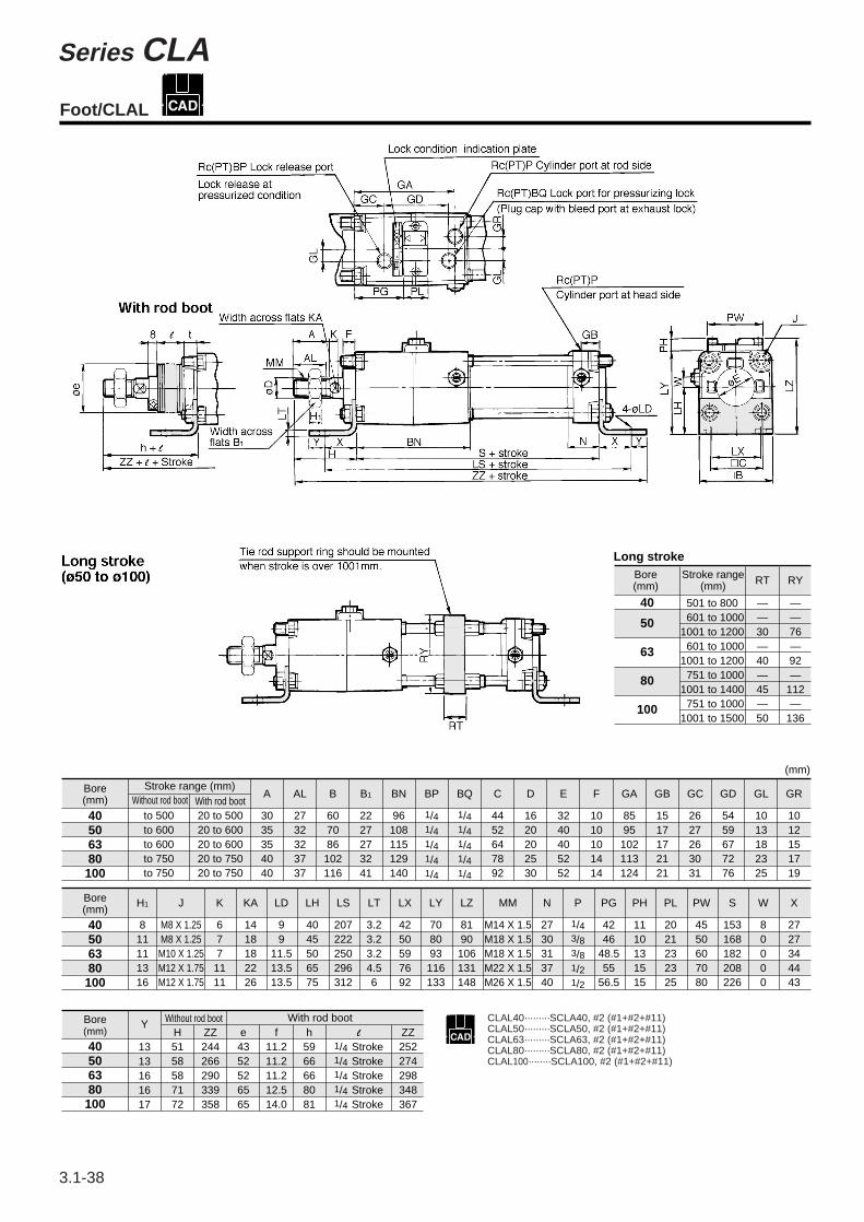
Long stroke
Without rod boot
Without rod boot
Foot/CLAL
With rod boot CLAL40·········SCLA40, #2 (#1+#2+#11)CLAL50·········SCLA50, #2 (#1+#2+#11)CLAL63·········SCLA63, #2 (#1+#2+#11)CLAL80·········SCLA80, #2 (#1+#2+#11)CLAL100········SCLA100, #2 (#1+#2+#11)
3.1-38
Series CLA
CL series(569-632) 3/5/99 11:55 AM Page 38
Bore(mm)
Long stroke range(mm)
to 500 to 600 to 600 to 750 to 750
501 to 800601 to 1000601 to 1000751 to 1000751 to 1000
A
3035354040
AL
2732323737
B
607086102116
B1
2227273241
BF
7181101119133
BN
96108115129140
BP
1/41/41/41/41/4
BQ
1/41/41/41/41/4
C
4452647892
D
1620202530
E
3240405252
GA
8595102113124
GB
1517172121
GC
2627263031
GD
5459677276
GL
1013182325
GR
1012151719
H1
811111316
J
M8 X 1.25M8 X 1.25M10 X 1.25M12 X 1.75M12 X 1.75
K
6771111
40506380
100
N
2730313740
P
1/43/83/81/21/2
PG
4246
48.555
56.5
PH
1110131515
PL
2021232325
PW
4550607080
S
153168182208226
W
80000
FV
607086102116
FD
99
11.513.513.5
FT
1212151818
FX
8090105130150
FY
4250597692
FZ
100110130160180
40506380
100
H67718789
ZZ241263307327
f19192121
h66668081
ZZ240258300319
BF
88105124140
506380
100
M
6101212
RT
30404550
RY
7692112136
FT
20232829
FX
120140164180
FY
586484100
FZ
144170198220
Without rod boot With rod boot
1001 to 12001001 to 12001001 to 14001001 to 1500
d5258588080
e4352526565
f1515
17.521.521.5
h5966668081
1/4 Stroke1/4 Stroke1/4 Stroke1/4 Stroke1/4 Stroke
ZZ223245262305324
ZZ215237254296315
H5158587172
(mm)
Long stroke Dimensions except those below are same as one in table above.
KA
1418182226
LZ
718099117131
M
1111141717
MM
M14 X 1.5M18 X 1.5M18 X 1.5M22 X 1.5M26 X 1.5
Stroke range (mm)
Stroke range (mm)
With rod boot20 to 50020 to 60020 to 60020 to 75020 to 750
Without rod boot
W/o rod boot
CLAF40·········SCLA40, #3 (#1+#3+#11)CLAF50·········SCLA50, #3 (#1+#3+#11)CLAF63·········SCLA63, #3 (#1+#3+#11)CLAF80·········SCLA80, #3 (#1+#3+#11)CLAF100········SCLA100, #3 (#1+#3+#11)
Bore(mm)
Bore(mm)
W/ rod bootl
Front Flange/CLAF
CL
MLGC
CNA
CB
CV/MVG
CXW
CXS
CXT
MX
MXU
MXS
MXQ
MXF
MXW
MXP
MG
MGP
MGQ
MGG
MGC
MGF
CY1
MY1
∗∗
3.1-39
Fine Lock Cylinder/Double Acting Single Rod Series CLA
CL series(569-632) 3/6/99 7:47 PM Page 39
**
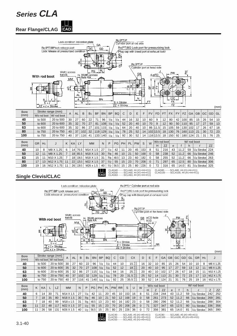
40506380100
40506380100
to 500 to 600 to 600 to 750 to 750
A
GR
3035354040
Bore(mm)
Bore(mm)
Bore(mm)
Stroke range (mm)
Stroke range (mm)
W/o rod boot W/ rod boot
W/o rod boot W/ rod boot
40506380100
to 500 to 600 to 600 to 750 to 750
20 to 500 20 to 600 20 to 600 20 to 750 20 to 750
20 to 500 20 to 600 20 to 600 20 to 750 20 to 750
AL
2732323737
A
3035354040
B
607086
102116
BN
96108115129140
B1
2227273241
BP BQ C
4452647892
CD
1012162025
D
1620202530
E
3240405252
F
1010101414
GA
8595102113124
GB
1517172121
GC
2627263031
GD
5459677276
GL
1013182325
GR
1012151719
H1
811111316
J
M8 X 1.25M8 X 1.25M10 X 1.25M12 X 1.75M12 x 1.75
CX
151825
31.535.5
1012151719
H1
811111316
K
677
1111
KA
1418182226
LY
76.585.5106.5125.5139.5
N P
2730313740
PG
4246
48.55556.5
PH
1110131515
PL
2021232325
PW
4550607080
S
153168182208226
WH
80000
5158587172
ZZ216238255297316
ZZ224246263306325
e4352526565
f11.211.211.212.514.0
h5966668081
J
M8 X 1.25M8 X 1.25M10 X 1.25M12 X 1.75M12 X 1.75
MM
M14 X 1.5M18 X 1.5M18 X 1.5M22 X 1.5M26 x 1.5
2732323737
607086
102116
AL B B1
2227273241
7181101119133
96108115129140
BF BN BP
1/41/41/41/41/4
1/43/83/81/21/2
1/41/41/41/41/4
1/41/41/41/41/4
1/41/41/41/41/4
4452647892
BQ C D
1620202530
3240405252
1010101414
E F
607086102116
FV FD
99
11.513.513.5
1212151818
8090105130150
FT FX FY
4250597692
100110130160180
8595102113124
FZ GA
1517172121
GB GC
2627263031
5459677276
1013182325
GD GL
–0.1–0.3–0.1–0.3–0.1–0.3–0.1–0.3–0.1–0.3
40506380100
KA
1418182226
K
6771111
L
3035404858
LZ
718099117131
P
1/43/83/81/21/2
N
2730313740
PG
4246
48.55556.5
PH
1110131515
PW
4550607080
PL
2021232325
RR
1012162025
S
153168182208226
U
1619232836
W
80000
H5158587172
Z234261280327356
ZZ244273296347381
e4352526565
f11.211.211.212.514.0
h5966668081
Z242269288336365
ZZ252281304356390
MM
M14 X 1.5M18 X 1.5M18 x 1.5M22 X 1.5M26 X 1.5
1/4 Stroke1/4 Stroke1/4 Stroke1/4 Stroke1/4 Stroke
1/4 Stroke1/4 Stroke1/4 Stroke1/4 Stroke1/4 Stroke
(mm)
(mm)
Bore(mm)
W/o rod boot W/ rod boot
W/o rod boot W/ rod boot
l
l
Single Clevis/CLACCLAG40·········SCLA40, #4 (#1+#4+#11)CLAG50·········SCLA50, #4 (#1+#4+#11)CLAG63·········SCLA63, #4 (#1+#4+#11)
CLAG80·········SCLA80, #4 (#1+#4+#11)CLAG100········SCLA100, #4 (#1+#4+#11)
CLAC40·········SCLA40, #5 (#1+#5+#11)CLAC50·········SCLA50, #5 (#1+#5+#11)CLAC63·········SCLA63, #5 (#1+#5+#11)
CLAC80·········SCLA80, #5 (#1+#5+#11)CLAC100········SCLA100, #5 (#1+#5+#11)
Rear Flange/CLAG
3.1-40
Series CLA
CL series(569-632) 99.2.20 5:04 PM Page 40
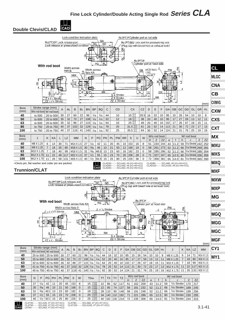
*Clevis pin, flat washer and cotter pin are packed.
Trunnion/CLAT
Double Clevis/CLAD
CLAD40·········SCLA40, #6 (#1+#6+#11)CLAD50·········SCLA50, #6 (#1+#6+#11)CLAD63·········SCLA63, #6 (#1+#6+#11)
CLAD80········· SCLA80, #6 (#1+#6+#11)CLAD100········SCLA100, #6 (#1+#6+#11)
40506380100
40506380100
M8 X 1.25M8 X 1.25M10 X 1.25M12 X 1.75M12 X 1.75
to 500 to 600 to 600 to 750 to 750
20 to 500 20 to 600 20 to 600 20 to 750 20 to 750
A
3035354040
J
677
1111
AL
2732323737
K
M14 X 1.5 M18 X 1.5 M18 X 1.5 M22 X 1.5 M26 X 1.5
MM
2730313740
N
4246
48.555
56.5
P
1/43/83/81/21/2
PG
1110131515
PH
2021232325
PL
4550607080
PW
1012162025
RR
153 168 182 208 226
S
1619232836
U
8 0 0 0 0
WH5158587172
234 261 280 327 356
Z244 273 296 347 381
ZZ1418182226
KA
3035404858
L
718099
117 131
LZ
B
607086
102116
B1
2227273241
BN
96108115129140
BP
1/41/41/41/41/4
1/41/41/41/41/4
BQ C
4452647892
CD
1012162025
CZ
29.538496164
D
1620202530
E
3240405252
F
1010101414
GA
8595102113124
GB
1517172121
GC
2627263031
GD
5459677276
GL
1013182325
GR
1012151719
H1
811111316
CX
151825
31.535.5
+0.3+0.1
+0.3+0.1
+0.3+0.1
+0.3+0.1
+0.3+0.1
242 269 288 336 365
Z252281304356390
ZZ4352526565
e11.211.211.212.514.0
f5966668081
h
Bore(mm)
Bore(mm)
Stroke range (mm)W/o rod boot W/ rod boot
(mm)
1/4 Stroke1/4 Stroke1/4 Stroke1/4 Stroke1/4 Stroke
W/o rod boot W/ rod bootl
–0.032 –0.059 –0.032 –0.059 –0.040 –0.073 –0.040 –0.073
CLAT40········SCLA40, #7 (#1+#7+#11)CLAT50········SCLA50, #7 (#1+#7+#11)LAT63·········· SCLA63, #7 (#1+#7+#11)
CLAT80········· SCLA80, #7 (#1+#7+#11)CLAT100········SCLA100, #7 (#1+#7+#11)
40506380100
170 189 199 230 244
217 240 256 295 315
4352526565
11.211.211.212.514.0
5966668081
2730313740
424648.55556.5
1110131515
2021232325
4550607080
153168182208226
80000
2222283440
8595
110 140 162
627490
110 130
117127148192214
5158587172
162181191221235
209232248286306
1/43/83/81/21/2
15 15182525
–0.032 –0.059 1/4 Stroke
1/4 Stroke1/4 Stroke1/4 Stroke1/4 Stroke
40506380100
25 to 500 25 to 600 32 to 600 41 to 750 45 to 750
25 to 500 25 to 600 32 to 600 41 to 750 45 to 750
Z ZZe f h
A
3035354040
N PG PH PL PW S W TT TX TY TZH Z ZZ
TDe8
AL
2732323737
B
607086
102116
B1
2227273241
BN
96108115129140
BP BQ
1/41/41/41/41/4
P
1/41/41/41/41/4
C
4452647892
D
1620202530
E
3240405252
F
1010101414
GA
8595102113124
GB
1517172121
GC
2627263031
GD
5459677276
GL
1013182325
GR
1012151719
H1
811111316
K
677
1111
KA
1418182226
LZ
718099
117131
J
M8 X 1.25M8 X 1.25M10 X 1.25M12 X 1.75M12 X 1.75
MM
M14 X 1.5M18 X 1.5M18 X 1.5M22 X 1.5M26 X 1.5
W/ rod boot
(mm)
Bore(mm)
W/o rod boot W/ rod bootl
Bore(mm)
Stroke range (mm)W/o rod boot
CL
MLGC
CNA
CB
CV/MVG
CXW
CXS
CXT
MX
MXU
MXS
MXQ
MXF
MXW
MXP
MG
MGP
MGQ
MGG
MGC
MGF
CY1
MY1
***
3.1-41
Fine Lock Cylinder/Double Acting Single Rod Series CLA
CL series(569-632) 99.2.20 5:04 PM Page 41
∗∗
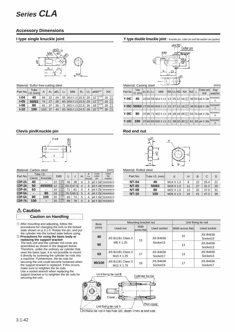
Material: Sulfur free-cutting steel
I type single knuckle joint
Clevis pin/Knuckle pin Rod end nut
Y type double knuckle joint ∗ Knuckle pin, cotter pin and flat washer are packed.
Part No.
I-04I-05I-08I-10
A
697491
105
A1
22273737
øE1
24283640
L1
55607183
MM
M14 X 1.5M18 X 1.5M22 X 1.5M26 X 1.5
R1
15.515.522.524.5
U1
20202628
øND H10
12121820
NX
16162830
TubeI.D. (mm)
4050/63
80100
+0.070 0+0.070 0+0.070 0+0.084 0
–0.1–0.3–0.1–0.3–0.1–0.3–0.1–0.3
Material: Carbon steel
Part No.Clevis Knuckle
CDP-2ACDP-3ACDP-4ACDP-5ACDP-6ACDP-7A
Dd9 L
101216182025
4655.571
76.58388
l
3847.561
66.57378
m
445555
dCut
through
334444
Usedcotter
pin
ø3 X 18l
ø3 X 18l
ø4 X 25l
ø4 X 25l
ø4 X 30l
ø4 X 36l
Usedflat
washer
“MIGAKIMARU”10
“MIGAKIMARU”12
“MIGAKIMARU”16
“MIGAKIMARU”18
“MIGAKIMARU”20
“MIGAKIMARU”24
Tube I.D.
405063–80100
–40/50/63
–80
100 –
–0.040–0.076–0.050–0.093–0.050–0.093–0.050–0.093–0.065–0.117–0.065–0.117
Material: Casting steel
Part No.
(mm)
Y-04C
Y-05C
Y-08C
Y-10C
A1
22
27
37
37
E1
24
28
36
40
L1
55
60
71
83
RR1
13
15
19
21
U1
25
27
28
38
ND
12
12
18
20
NZ L
38
38
55
61
ø3 X 18l
ø3 X 18l
ø4 X 25l
ø4 X 30l
55.5
55.5
76.5
83
NX
16
16
28
30
MM
M14 X 1.5
M18 X 1.5
M22 X 1.5
M26 X 1.5
40
50/63
80
100
TubeI.D. (mm)
Cotter pinsize
Flatwasher
+0.3+0.1
+0.3+0.1
+0.3+0.1
+0.3+0.1
(mm) Material: Rolled steel
Part No.
NT-04NT-05NT-08NT-10
Tube I.D. (mm)
4050/63
80100
d
M14 X 1.5M18 X 1.5M22 X 1.5M26 X 1.5
H
8111316
B
22273241
C
25.431.237.047.3
D
21263139
Mounting bracket nutWidth
across flats
40
50
80/100
Width across flats
10
13
13
17
Unit fixing tie rod
Used socketUsed socketUsed nutBore(mm)
JIS B4636Socket10
JIS B4636Socket13
JIS B4636
Socket13
JIS B1181 Class 3
M8 X 1.25
JIS B1181 Class 3M10 X 1.25
JIS B1181 Class 3M12 X 1.75
13
17
19
Accessory Dimensions
Caution on HandlingCaution
q After mounting and adjusting, follow the procedures for changing the lock to the locked state shown on p.3.1-5. Rotate the pin, and put the cylinder into the locked state before using.
w Precautions for using the basic body or replacing the support bracket:The lock unit and the cylinder rod cover are assembled as shown in the diagram below. Therefore, unlike the ordinary air cylinder that uses the basic type, it is not possible to mount it directly by screwing the cylinder tie rods into a machine. Furthermore, the tie rods for securing the unit could become loosened when the support bracket is replaced. If this occurs, make sure to retighten the tie rods.Use a socket wrench when replacing the support bracket or to retighten the tie rods for securing the unit.
“MIGAKIMARU”12
“MIGAKIMARU”12
“MIGAKIMARU”18
“MIGAKIMARU”20
63JIS B4636Socket17
JIS B4636Socket19
JIS B4636Socket13
JIS B4636Socket17
3.1-42
Series CLA
CL series(569-632) 3/5/99 12:11 PM Page 42


![Cascading Style Sheets (CSS) - aurelio.staff.gunadarma.ac.idaurelio.staff.gunadarma.ac.id/Downloads/files/30700/Cascading+Style+Sheets.pdf · Lock background image [background-attachment]](https://img.pdfslide.net/doc/110x75/5d229c6588c993f2168dacda/cascading-style-sheets-css-stylesheetspdf-lock-background-image-background-attachment.jpg)