Embed Size (px)
Citation preview

FINE MILLING and MICRO MILLING…to the next “level”
October, 2015

Why Fine / Micro Milling?
• Remove wheel ruts or uneven pavement surfaces• Roughen pavement surface to improve adhesion of thin wearing course
or seal coat applications• Restore skid-resistance to worn, slippery pavement surfaces• Allow milling crew to operate independently from paving due to surface
texture that allows opening to traffic• Cost savings related to the reduced amount of material needed• Potential to allow traffic to use surface as milled over extended periods• Reduce the amount of tack, as the peak-to-valley ridges decrease
What can it do for you?

Why Fine / Micro Milling?
Material Removed New Material Required Haul Trucks Time Required For Mill & Fill Overall Contractor Costs Overall Cost of Project
What can it do for you?

Plan Work To Meet Job Requirements
Restoring Elevations• Smoothness specification
usually tied to bump detection
• Cold planer should do the bulk of the smoothness improvement
• While also providing good texture

Plan Work To Meet Job Requirements
Creating Profile (Slope)• Cold planer has same
slope capability as a paver
• Whenever possible, cold planer should use automatic slope control to create specified profile

Surface texture• Texture contributes to
smoothness – especially thin lift over milled surface
• Depends on:-- milling speed-- condition of rotor tools-- rotor tool spacing-- cut depth (delamination)
Plan Work To Meet Job Requirements

• Properly milled surface simplifies the paving process
• Improper milling creates problems for the paving process
• What problems do you see?
Condition of Milled Surface

9
Scalloping-Too fast forward speed

Best practice- Drum Speed
10
Drum speed vs. Travel speed.• Consider a reasonable ratio of Cutter RPM to
Travel speed to maintain quality.• Most cutter drums turn about 100 rpm.• When the Machine moves forward, a tool
striation mark is created approx- 3.5” to 4” long (10 cm)
• When the travel speed exceeds the drum rpm, the machine outruns the cutter.

11
Travel speed continued
• When the cutting tools are not overlapping their adjacent tool striation, a very poor quality surface finish results.
• The surface can become scalloped, and /or just individually gouged.
• An acceptable ”rule of thumb” is that the travel speed not exceed 2/3 of the cutter drum RPM.
• EX----100RPM at 66 FPM• This allows a 1/3 overlap in the striations
between adjacent tools.
• Slope does not care about depth
• High spots in the grade can cause the screed to drag
• Depth not always equal across mat width
• Emphasizes the need for quality control during milling step
Paving Under Slope Control
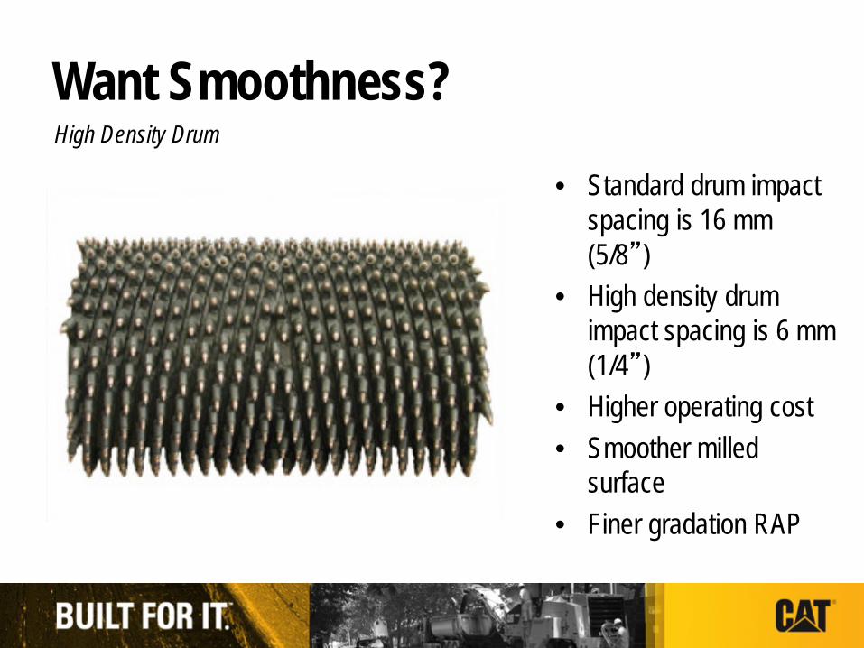
• Standard drum impact spacing is 16 mm (5/8”)
• High density drum impact spacing is 6 mm (1/4”)
• Higher operating cost• Smoother milled
surface• Finer gradation RAP
Want Smoothness?High Density Drum
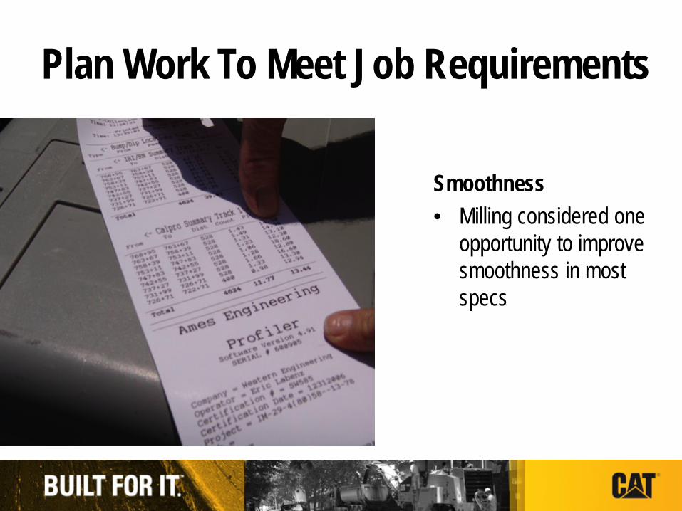
Smoothness• Milling considered one
opportunity to improve smoothness in most specs
Plan Work To Meet Job Requirements

Worn Drum Cutting a Crown• Worn carbide tool holders can also create another
issue.• Typically, the rotating tools in the center of the drum
will see more material flow.• This can create a crown in the milled surface.• This issue is somewhat corrected by the moleboard,
but the moleboard can then wear to the crowned shape.
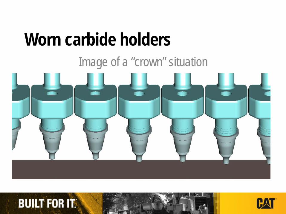
Worn carbide holdersImage of a “crown” situation

Evolution of Cutting Tools

• Polycrystalline Diamond Powder• Tungsten Carbide Substrate• Sinter the two elements together using a
proprietary high pressure/high temperature press process to form the StingerTM tip
• Braze together the tip, carbide bolster, and hardened steel body
Microscopic View
Hard Frame Press
Cat® Diamond Bit Anatomy
Each phase of this design acts as building block to provide longer wear through improved thermal characteristics.

540 Asphalt Bit
• ½” diameter carbide bolster brazed to the tip and hardened steel body.
• Application– Asphalt ONLY
625 Extended Life Bit
• Bullet shaped carbide bolster brazed to the tip and hardened steel body
• Applications– Asphalt– Asphalt off of Concrete
STINGER POLYCRYSTALLINE DIAMOND
TUNGSTEN CARBIDE
STEEL

• Asphalt Milling Applications• Proprietary One-Piece Design
− Replaces the need for a tool holder• Non-Rotating Bit
− Because the StingerTM tip is wear resistant there is no need for the bit to rotate and more uniform wear provides a better cut
• Bits available to fit most drumtypes:− Cat− Wirtgen HT11− Kennametal− Sollami− NovaPick
Features

Benefits

NEW ENGLAND
• BODY WASH• SAME FLAT PATTERN• SAME GAUGE HEIGHT

SMOOTHER ROADS, BETTER FUEL ECONOMY, LOWER VIBRATION
Diamond Teeth Stay Sharp• Reduced fuel consumption• Reduced rotor drivetrain
loads• Less vibration• Longer structural life• Component life• Improved operator comfort
Teeth Engage
Additional Benefits
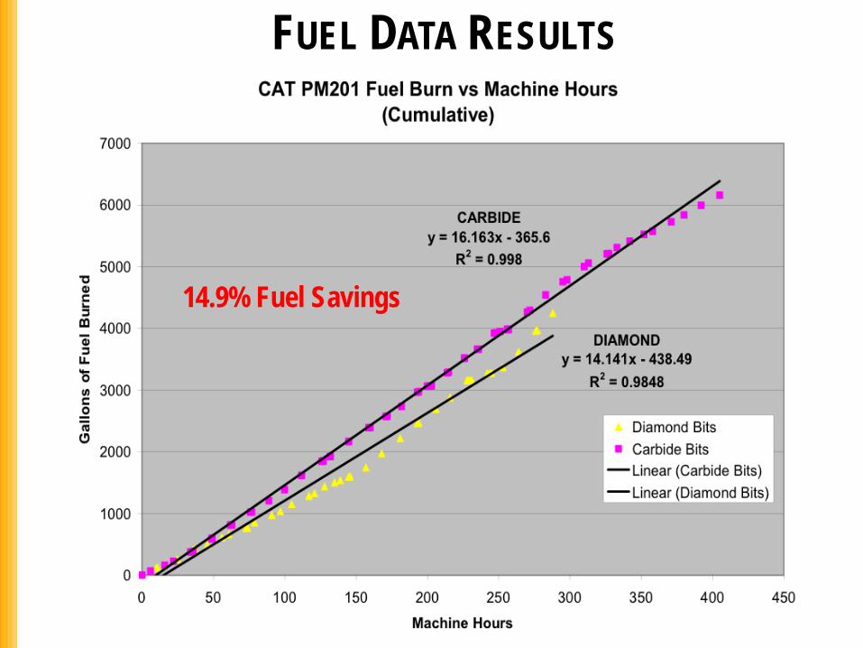
FUEL DATA RESULTS
14.9% Fuel Savings

26
Future
• More Fine and Micro Milling requirements
• Growth for Asphalt recycling and related savings
• Improved wear course life• Better Roads for less dollars

Thank YouThank You