Embed Size (px)
Citation preview
FINGERPRINT IMAGE SEGMENTATION USING HIERARCHICAL
TECHNIQUE
WAN AEZWANIBT WAN ABU BAKAR
This thesis is submitted as a partial fulfilment of the requirements for the
degree of Master of Science (Computer Science)
Faculty of Computer Science and Information System
Universiti Teknologi Malaysia
MAY 2000

SPECIAL TRIBUTES AND DEDICATIONS
My Family...
We, arwah cik, tok wan, brothers and sisters especially Pok Jih, Abang Har, Abang
Lee, Kak Ina, Kak Ini, Ajea, Da and Aliza that my eternal grateful thanks and full
gratitude goes to all of you that always neverendingly being there for me.
My seniors, juniors and colleagues...
Especially for Azmi Kamis and Masrina Sulong for welcoming me in the world of
graphics fingerprint image. Also for my roommate Kak Shidah, my colleagues Kak
Rad, Kak Teni, Kak Ana and Kak Lili for your support and encouragement.
My proof readers...
Especially for Hazinah Kutty Mummy, thanks for everything.
My fiance...
Especially for Abang Mus, I will never be able to produce this report if not for the
effort of him with his productive comments and cross every T’s and dots every I’s.
And lastly...
To all who helps me in everything.

ACKNOWLEDGEMENT
A special recognition goes to my project supervisor, Prof. Dr. Ghazali Sulong for his
superb ideas and smart guidance that given me much effort to complete this project.
Without his guidance, I don’t think I can further my knowledge and experience in
developing the project.
A special thanks to all administration staffs of Faculty Of Computer Science and
Information System, that from time to time always incorporates me with the
management stuff and administration procedure and also to the technical staffs for
maintaining the technical support.
A profound thanks also goes to School of Graduate Studies, University of
Technology Malaysia for providing me a chance to further my study in the esteemed
educational organisation.

Fingerprints are the ridge and furrow patterns on the tip of the finger and its
verification is an important biometric technique for personal identification. The
quality of the fingerprint image is the most significant factor in a reliable matching
process. Thus, any pre-processing algorithm should aim to enhance the quality of the
existing features without creating false features. This scenario brings the idea of the
research. The research focus on the segmentation approach. The purpose of the study
is to identify a segmentation approach of fingerprint image by considering several
approaches namely Hierarchical technique and Region growing by pixel aggregation
technique. The process is vital when to apply next pre-processing stages i.e. thinning,
identifying between true and false minutiae and minutiae extraction process. The
research is supported by 50 samples of data that is collected through an available
fingerprint device. The development of this research is by using Delphi 3.0.

Cap jari merupakan corak batas dan galur yang terdapat pada jari manusia dimana
pengesahan pada setiap cap jari merupakan teknik biometrik yang penting untuk
pengenalan seseorang individu. Tahap kualiti pada imej cap jari merupakan faktor
yang signifikan untuk menjalani proses pemadanan yang boleh dipercayai. Oleh
sebab itu, setiap algoritma yang melibatkan peringkat pra-pemprosesan perlu
menekankan kepada peningkatan tahap kualiti ciri-ciri yang ada pada imej cap jari
tanpa mewujudkan ciri-ciri yang salah. Senario sebegini memberi idea kepada kajian
untuk meneroka dan menumpukan kepada teknik segmentasi di dalam peringkat pra-
pemprosesan imej. Tujuan kajian dibuat adalah untuk mengenalpasti pendekatan
yang ada dalam proses segmentasi. Antara pendekatan yang diambilkira ialah Teknik
Hirarki dan juga Teknik Region growing by pixel aggregation. Proses segmentasi
penting untuk pengendalian proses yang seterusnya seperti penipisan, penentuan
antara minutiae yang benar atau yang salah dan juga proses pengekstrakan minutiae.
Kajian ini dibantu oleh 50 sampel data yang dikumpul melalui peranti imej cap jari
yang disediakan. Kajian ini dibangunkan dengan menggunakan perisianDelphi 3.0.

CHAPTER CONTENTS PAGE
TITLE OF THESIS i
DECLARATION ii
SPECIAL TRIBUTES & DEDICATIONS iii
ACKNOWLEDGEMENT iv
ABSTRACT v
ABSTRAK vi
TABLE OF CONTENTS vii
LIST OF FIGURES x
LIST OF TABLES xiii
LIST OF ABBREVIATIONS xiv
LIST OF APPENDICES xv
CHAPTER I INTRODUCTION
1.1 Introduction 1
1.1.1 History of fingerprint 1
1.1.2 The nature of fingerprint 3
1.1.3 Biometric overview 4
1.2 Background of the problem 6
1.3 Statement of the problem 8
1.4 Purpose / Objectives of the study 9
1.5 Theoretical framework 9
1.6 Importance of the study 11
1.7 Scope of the study 11
1.8 Definition of terms 12
1.9 Summary 14

CHAPTER II LITERATURE REVIEW
2.1 Introduction 15
2.1.1 Minutiae structures & Fingerprint patterns 16
2.2 Image acquisition 20
2.3 Fingerprint image quality enhancement 22
2.4 Fingerprint image quality control 23
2.5 Fingerprint image orientation estimation 24
2.6 Fingerprint image segmentation methodology 27
2.6.1 Block direction technique 28
2.6.2 Hierarchical technique 29
2.6.3 Region-Oriented technique 30
2.7 Summary 33
CHAPTER in RESEARCH DESIGN
3.1 Introduction 34
3.2 Research design 34
3.3 Research operational framework 35
3.4 Data sources & Instrumentation 37
3.4.1 Hardware requirements 3 7
3.4.2 Software requirements 37
3.5 Research procedures & Data analysis 38
3.6 Assumptions & Limitations 38
3.7 Summary 39
CHAPTER IV RESULT AND DISCUSSION
4.1 Introduction 40
4.2 System development 40
4.2.1 Interface window 41
4.2.2 Segmentation interface window 42
4.3 System implementation 44
4.3.1 Image acquisition 44

4.3.2 Result of noise removal process by median 47
3x3
4.3.3 Result of enhancement process 49
4.3.4 Result of orientation process 49
4.3.5 Result of segmentation process 51
4.4 System analysis 54
4.4.1 System performance 54
4.4.2 Quality control test 55
4.4.3 Orientation test 56
4.4.4 Segmentation test 57
4.5 Summary 61
CHAPTER V CONCLUSION
5.1 Discussion 63
5.2 Benefits 64
5.3 Suggestion 64
5.4 Future Works 64
5.5 Conclusion 65
BIBLIOGRAPHY
APPENDICES
66
69

NO OF FIGURES TITLE OF FIGURES PAGE
1.1 Schematic Block Diagram of an AFIS 3
1.2 Biometric Applications 5
1.3 Schematic Block Diagram of Fingerprint Image 10
Processing
2.1 Arch 17
2.2 Tented arch 17
2.3 Right loop 18
2.4 Left loop 18
2.5 Whorl 19
2.6 Representation of core and delta 19
2.7 Normal Minutiae : Line endings and bifurcation 20
2.8 (a) Examples of images from live-scan (inkless) 21
biometric scanner a) good image b) bad image c)
too dry-skin image d) too wet-skin image
xi
21
23
25
26
32
32
36
41
42
43
44
45
46
Examples of images from off-line (ink) a) under-
inked image b) over-inked image
Image Analysis
16x16 block mapping on image
Sobel Mask a) Image 3x3 region mask in gray
scale 0-255 b) Mask for Gx for centre point of 3x3
region c) Mask for Gx for centre point of 3x3 region
Original image
Segmentation result using an absolute difference of
less than 3 between intensity levels
Research Operational Framework
System’s interface window
Open button dialog box
Example of interface window when segmentation
process is done
Region growing interface window
Examples of live-scan images scanned through
Biometric-Scanner Veridicom Passprint
Examples of off-line scanned images through HP
Deskscan II scanner
xii
46
47
48
49
50
50
52
53
55
55
56
Dirt (A and B) on veridicom passprint device
caused a noisy images
Over-inked (X) and under-inked (Y) images during
pressure caused damage in fingerprint ridges
Examples of images before and after Noise removal
using median 3x3
Examples of image enhancement using HighBoostl
without and with noise removal process
Image orientation by 4x4 block region, 8x8 block
region, 16x16 block region and 32x32 block region
Orientation line mapping by 8x8 block and 16x16
block
Location of ROI and its segmentation according to
4 different division of blocks (parameter : median
3x3, HB1, threshold value = 93)
The result of segmentation process by RG with 3
different threshold value according to 2 different
enhancement process
Quality control check for good image before
enhancement process
Quality control check for poor image before
enhancement process
Orientation test result

LIST OF TABLES
NO TABLE TITLE OF TABLE PAGE
4.1 FAR and FRR of images after QC 56
4.2 Processing time vs. quality by hierarchical 58
technique
4.3(a) Region growing by HP 1 60
4.3(b) Region growing by HB1 60

Dpi Dot per inch
FAR False Acceptance Ratio
FP Fingerprint Image
FRR False Rejection Ratio
FTIR Frustrated Total Internal Reflection
HB1 High Boost 1 filtering
HP Hewlett Packard
HP1 High Pass 1 filtering
ID Identification
Med 3x3 Median 3x3
QC Quality control check
RG Region growing
ROI Region of Interest
NO OF TITLE OF APPENDICES
APPENDICES
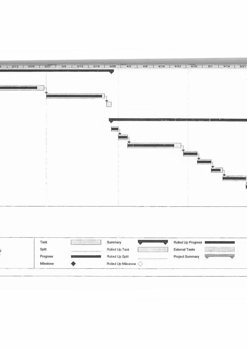
A GANTT CHART FOR PEOJECT I AND II
B FINGERPRINT PATTERN TYPES
C ORIGINAL SIZE OF FINGERPRINT IMAGE
SCANNED THROUGH BIOMETRICS-SCANNER
VERIDICOM PASSPRINT ( 300 x 300 PIXEL )
D RESULT OF 10 SAMPLES OF IMAGE
SEGMENTATION BY 4 X 4 AND 32 X 32 BLOCK
WITH HIERARCHICAL TECHNIQUE
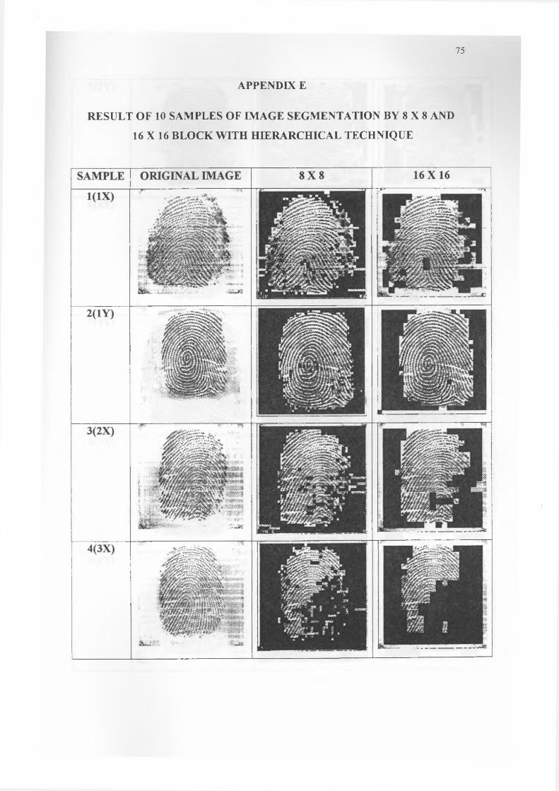
E RESULT OF 10 SAMPLES OF IMAGE
SEGMENTATION BY 8 X 8 AND 16X16 BLOCK
WITH HIERARCHICAL TECHNIQUE
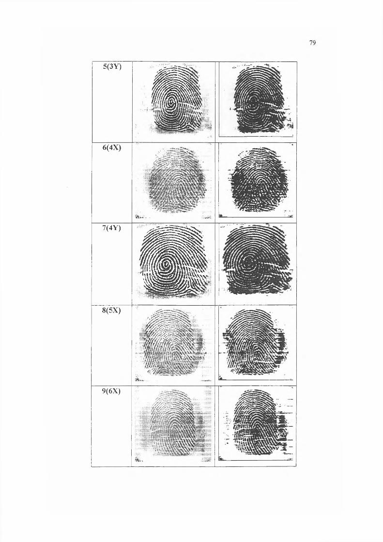
F RESULT OF 10 SAMPLES OF IMAGE
SEGMENTATION BY REGION GROWING BY
PIXEL AGGREGATION TECHNIQUE
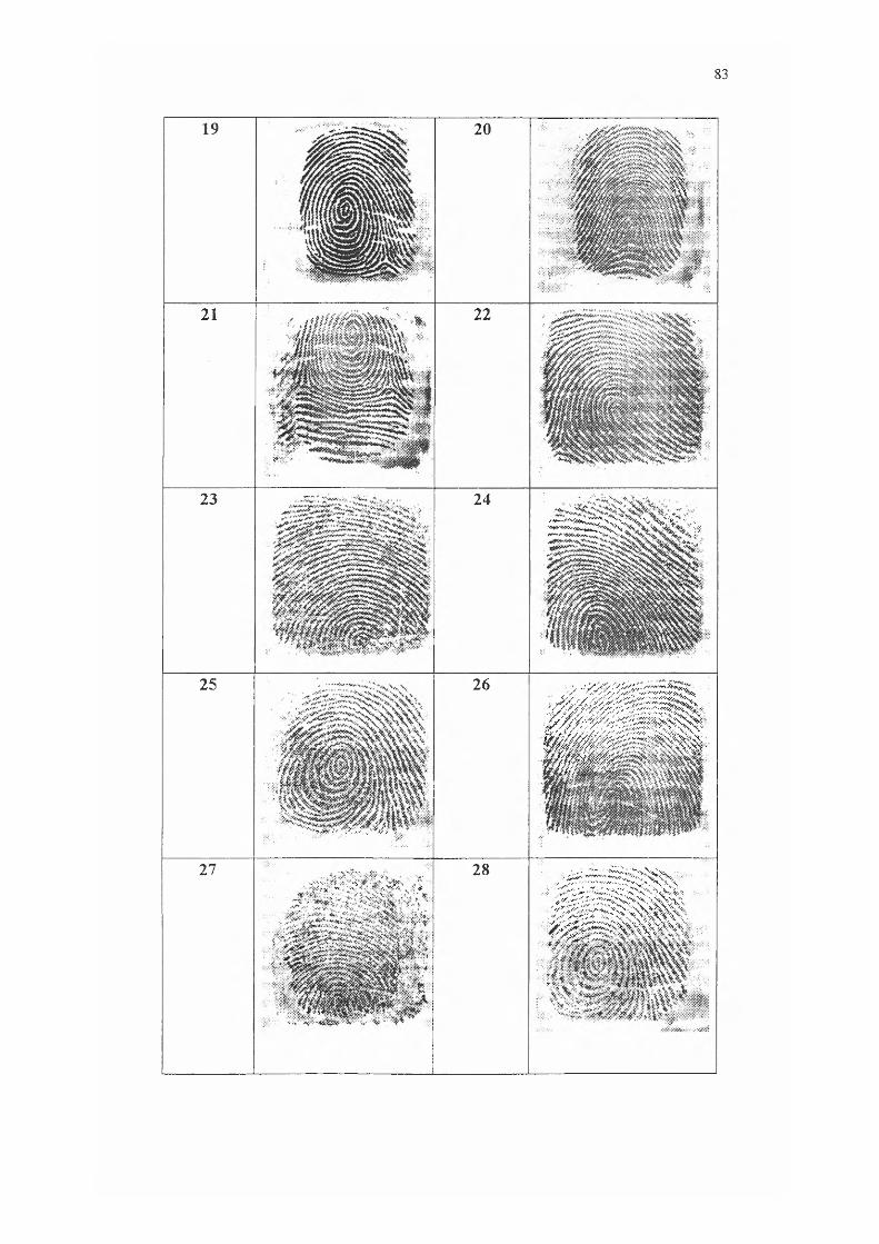
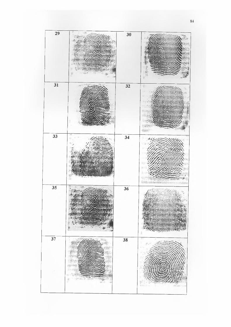
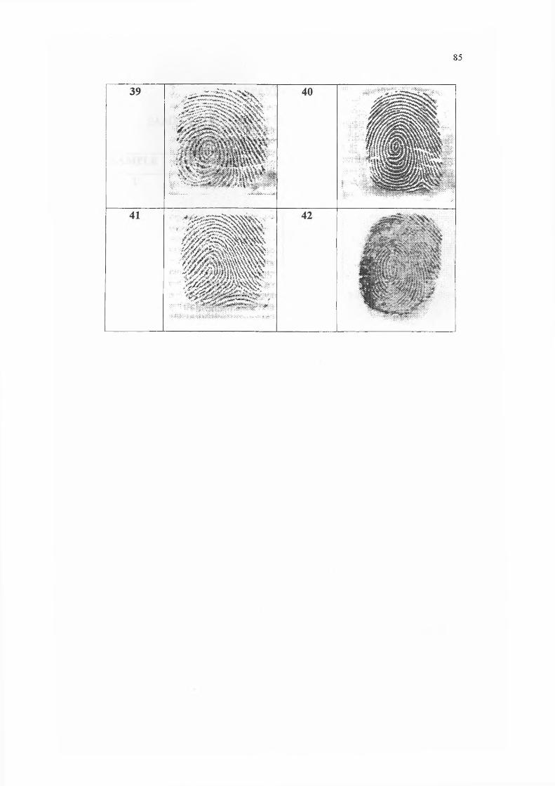
G SAMPLES OF 42 GOOD FINGERPRINT IMAGES
PAGE
69
70
71
72
75
78
81
H SAMPLES OF 8 POOR FINGERPRINT IMAGES 86

SOURCE CODE FOR SEGMENTATION BY
HIERARCHICAL TECHNIQUE
SOURCE CODE FOR SEGMENTATION BY
REGION GROWING BY PIXEL AGGREGATION
TECHNIQUE
CHAPTER I
INTRODUCTION
1.1 Introduction
1.1.1 History of fingerprint
The beginning of the fingerprint is not known. But for certain, there are
definite periods in its history. The first period started when human beings become
aware of fingerprint that such fingerprint is used as a mean of individual signature.
The second period then started with the development of fingerprint coding and filing
system and technique of searching for latent prints (Alobaidi, 1998).
Ancient Chinese and Babylon had been using fingerprints on clay tablets for
business transactions. Later, in 14th Persia century, various official government
papers had fingerprints until a doctor of one government officer observed that no two
fingerprints were exactly the same (Alobaidi, 1998).
In 1686, a professor of anatomy, Marcello Malphigi has noted the ridge,
spiral and loop which were the nature of fingerprint, but unfortunately he didn’t
mentioned about its value as tools for individual identification (Alobaidi, 1998).
Credit for early scientific contributions in fingerprinting is given to many
people especially Dr. Henry Faulds (1843 - 1930), Harris Wilder (1864 - 1928) and
Henrich Poll (1877 - 1939). The first scientific contribution was made by Francis
Galton (1822 - 1916). It was he who established the fact that no two fingerprints are
the same. He had established the individuality and permanence of fingerprints and
produced the first fingerprint classification system while in the mean time he
identified the unique characteristics of fingerprint, whereby it’s known as Galton’s
Details. He classified the patterns into three major types for filing purposes (Hughes,
1991).
A more advanced classification of fingerprints was made by Edward Henry
(1850 - 1931). Henry's classification as it becomes known, is the basis for all of
today's fingerprint classification schemes. The four major types in the Henry
classification are : arches, loops, whorls and composites (Hughes, 1991).
In 1923, a professor of anatomy, John Evangelist Purkinji discussed about 9
fingerprint patterns but he too made no attempt of the value of fingerprint for
personal identification.
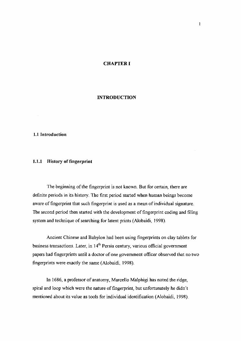
Starting on 1960s, Federal Bureau of Investigation (FBI) and Paris Police
Department had made a big investment to support the development of Automated
Fingerprint Identification System (AFIS) which is the system to identify the
fingerprint matching. Their effort were so successful that a large number of AFIS’s
are currently installed and in operation at law-enforcement agencies world-wide.
These systems have greatly improved the operational productivity of these agencies
and reduced the cost of hiring and training human fingerprint experts for manual
fingerprint identification. Automatic fingerprint identification rapidly grew beyond
law enforcement into civilian application. In fact, fingerprint-based biometric
systems are so popular that they have almost become the synonym of biometric
systems. Refer to Figure 1.1 to denote a schematic block diagram of an AFIS
(Kasaei, et al., 1997).
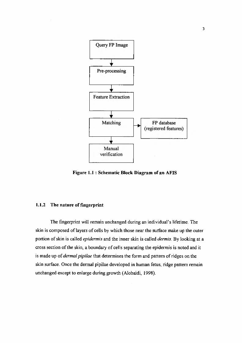
Figure 1.1: Schematic Block Diagram of an AFIS
1.1.2 The nature of fingerprint
The fingerprint will remain unchanged during an individual’s lifetime. The
skin is composed of layers of cells by which those near the surface make up the outer
portion of skin is called epidermis and the inner skin is called dermis. By looking at a
cross section of the skin, a boundary of cells separating the epidermis is noted and it
is made up of dermal pipilae that determines the form and pattern of ridges on the
skin surface. Once the dermal pipilae developed in human fetus, ridge pattern remain
unchanged except to enlarge during growth (Alobaidi, 1998).

1.1.3 Biometric Overview
Any human physiological or behavioural characteristic can be used to make a
personal identification as long as it satisfies following requirements (Jain, et al.,
1997):
• Universality means that every person should have the characterisation.
• Uniqueness indicates that no two person should be the same in terms of
characteristics.
• Permanence means that characteristics should be invariant with time.
• Collectability indicates that the characteristics can be measured
quantitatively.
In practice, there are some other important requirements namely :
• Performance that refers to the achievable identification accuracy, the resource
requirements to achieve an acceptable identification accuracy and the
working or environmental factors that affect the identification accuracy.
• Acceptability that indicates to what extent people is willing to accept
biometric system.
• Circumvention that refers to how easy it is to fool system by fraudulent
techniques.
Biometrics is a rapidly evolving technology that has been widely used in
forensics such as criminal identification and person security and has the potential to
be widely adopted in a very broad range of civilian applications as in Figure 1.2 :
• Banking security such as electronic fund transfers, ATM security, check
cashing, and credit card transaction.
• Physical access control such as airport access control.
• Information system security such as access to databases via login privileges.
• Government benefits distribution such as welfare disbursement programs.
• Customs and immigration such as the Immigration and Naturalisation Service
Passenger Accelerated Service System (INSPASS) which permits faster
immigration procedures based on hand geometry.
• National ID system which provide a unique ID to the citizens and integrate
different government services.
• Voter and driver registration providing registration facilities for voters and
drivers.
tirateefit I I•.rVlpyK’.VKr’yXV. ff. .ThvXvXvX
y , 'O s + •> 't//* s''4 , "<* *s / 1" f**f ' s/' '
A tm t® m m m t
Figure 1.2 : Biometric Applications
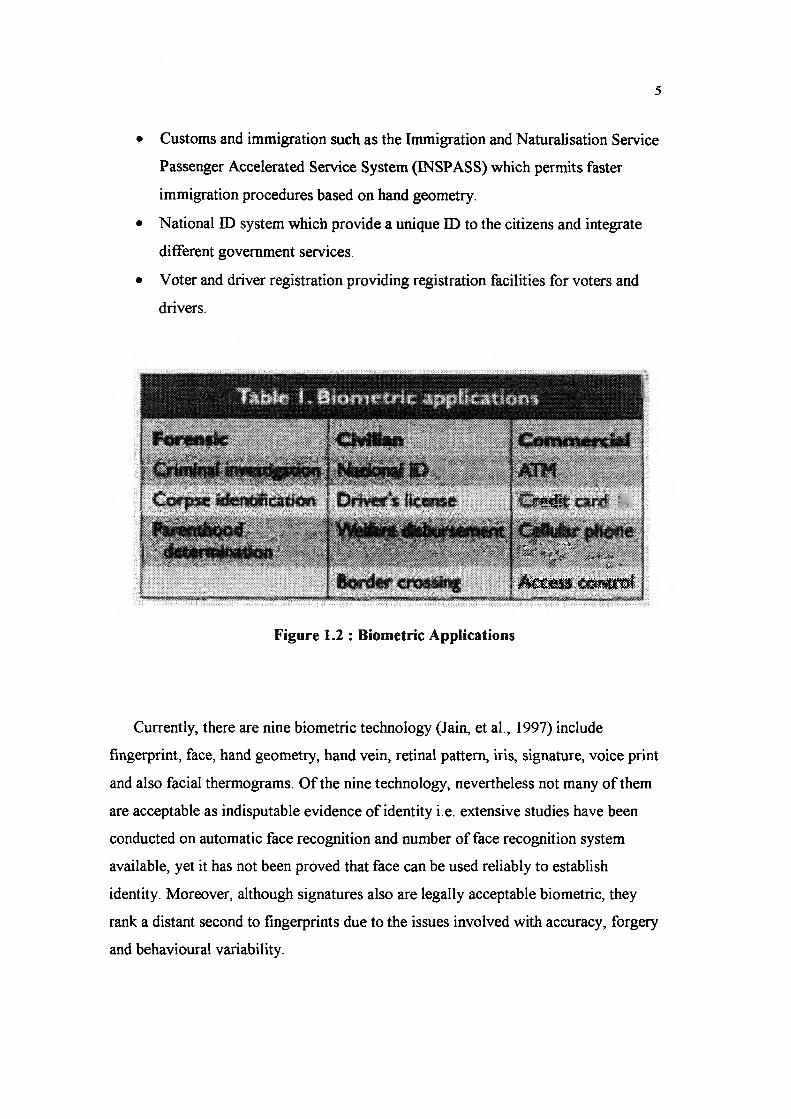
Currently, there are nine biometric technology (Jain, et al., 1997) include
fingerprint, face, hand geometry, hand vein, retinal pattern, iris, signature, voice print
and also facial thermograms. Of the nine technology, nevertheless not many of them
are acceptable as indisputable evidence of identity i.e. extensive studies have been
conducted on automatic face recognition and number of face recognition system
available, yet it has not been proved that face can be used reliably to establish
identity. Moreover, although signatures also are legally acceptable biometric, they
rank a distant second to fingerprints due to the issues involved with accuracy, forgery
and behavioural variability.
For the recent time, the only legally accepted, readily automated and mature
biometric techniques is the AFIS which has been used and accepted in forensics
since the early 1970s.
1.2 Background of the problem
The local ridge characteristics and their relationships exclusively determine the
uniqueness of a fingerprint. On top of that, it is widely used as a personal
identification for automated systems.
One of the main problems in extracting structural features is the presence of noise
(unwanted information that can result from the image acquisition process)
in the fingerprint image. Commonly used method for taking fingerprint impressions
involved applying a uniform layer of ink on the finger and rolling the finger on
paper. These events cause the following types of problems (Ratha, et al., 1996):
• Over-inked areas of the finger create smudgy areas in the image.
• Breaks in ridges are created by under-inked areas.
• The skin being elastic in nature can change the positional characteristics of
fingerprint features depending upon the pressure being applied on the
fingers.
But then although inkless methods for taking fingerprint impressions are now
available, these methods still suffer from the positional shifting caused also by skin
elasticity. Poor quality fingerprint images pose important problems in minutiae
extraction, causing the disappearance of real ones and/or the presence of spurious
(false) i.e. true bifurcations very often disappear due to insufficient pressure of the
finger. On the other hand, true endings disappear when the finger is pressed too hard
producing false ridge continuity.

• Inconsistent contact: the act of sensing distorts the finger. Determined by the
pressure and contact of the finger on the glass platen, 3-dimensional shape of
the finger gets mapped onto the 2-dimensional surface of the glass platen.
This mapping function is uncontrolled and results in different inconsistently
mapped fingerprint images across the impressions.
• Nonuniform contact: Ridge structure of a finger would be completely
captured if ridges of the part of the finger being imaged are in complete
optical contact with the glass platen. However, the dryness of the skin, skin
disease, sweat, dirt and humidity in the air all confound the situation,
resulting in nonideal contact situation : some part of the ridges may not come
in complete contact with the platen, and regions representing some valleys
may come in contact with the glass platen. This results in ‘noisy’ low-contrast
images, leading to either spurious minutiae or missing minutiae.
• Irreproducible contact: Manual work, accidents, inflict injuries to the finger,
thereby changing the ridge structure of the finger either permanently or
semipermanently. This may introduce additional spurious minutiae.
• Sensing a c t: the act of sensing itself adds noise to the image. For example,
residues are leftover from the previous fingerprint capture. A typical finger-
imaging system distorts the image of the object being sensed due to imperfect
imaging conditions. In the image acquisition stage i.e. FTIR sensing scheme,
there is a geometric distortion because the image plane is not parallel to the
glass platen.

Fingerprint recognition remains as one of the most prominent biometric
identification methods. The quality of the fingerprint image is the most significant
factor in a reliable matching process. Any pre-processing algorithm should aim to
enhance the quality of the existing features without creating false features. The whole
scenario is presented by the main research question :
How to improve the quality offingerprint features through the pre-processing steps
in order to ease the process o f forwarding steps in fingerprint image processing ?
The following 3 major issues are taken into account to answer the main research
question stated above.
1. Why choose fingerprint instead offace, hand-written or speech ?
• What is the science o f fingerprint ?
• How many patterns are there ?
2. How can fingerprint images are recognised ?
• What techniques did previous authors use ?
• What are the distinct steps involved in pre-processing ?
• What is done in segmentation process ?
• What is the significance o f the process i f it's going to be done ?
3. What are the algorithms available in segmentation stage ?
• What algorithm available here based on tool constraint ?
• What algorithm is going to be considered ?
• Does it have a future value ?
4. What is the difference between segmentation andfiltering technique?
• How does it differ ?
• What is the significance between those two ?

The purpose of the study is to identify a robust segmentation approach of
fingerprint image by experimenting several approaches. Segmentation is the process
of isolating between the foreground and the background of the fingerprint image with
the purpose to identify the ridge line. This process is vital when to apply the thinning,
identifying between true and false minutiae, minutiae extraction and other pre
processing stages in the field of image processing. Supporting by 50 of sample data,
the research project is a complete and comprehensive for recognition system that
accurately supported the fingerprint matching or classification. The main objectives
of this research proposal are :
• To identify techniques involved in segmentation process that is to be
applied in fingerprint images.
• To evaluate and analyse the robust segmentation techniques which is to
be used in fingerprint recognition methodology.
1.5 Theoretical framework
To propose a technique for fingerprint image segmentation, the author has taken
into a great consideration about the field in image processing and pattern recognition
area. The theoretical framework of this research is shown in Figure 1.3. The dotted
line indicates the focus area of the research.
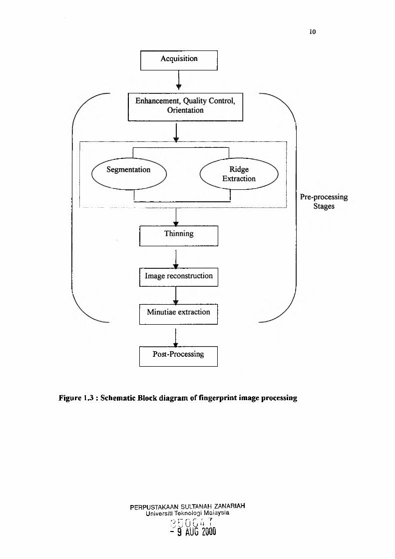
Acquisition
T ________Post-Processing
Figure 1.3 : Schematic Block diagram of fingerprint image processing
PERPUSTAKAAN SULTANAH ZANARIAH Universiti leknologi Malaysia
3 G 0 !j u 7 - 9 AUG 2000

Although the fingerprint image is scanned through Biometric Scanner-Veridicom
Passprint, not all the images are in a good quality. Skin elasticity or dirt on the
scanner screen may effect in a bad quality and hence introduce noise or distortion to
fingerprint image. And if the rolled fingerprint is to be used, the problem is the
intensity level of the ink on the rolled fingerprint also may occur. Thus, the
development of a fast, accurate and robust recognition system in the pre-processing
stage is very important with the goal to create an effective database for fingerprint
matching and retrieving. Focus area of the research is on the segmentation and ridge
extraction process. This process is done after image enhancement, quality control and
image orientation process (Azmi, 2000) and before the next stages i.e. thinning,
minutiae extraction and post-processing can be undertaken.
1.7 Scope of the study
Main focus area of this research project is on the segmentation process. But to
end up with the process, the fingerprint image must be pre-processed through the
following steps :
i. Fingerprint image is live-scanned through a biometric device and manual
scanned which restricted to 50 images in TIFF (Tagged Image File
Format).
ii. The quality of image is then enhanced by conducting the process of noise
removal using Median Filtering 3x3 technique and also through the
process of image sharpening using High Boostl filtering (Azmi, 2000)
and High Passl filtering.
iii. Histogram is then plotted and thereafter, the process of quality control is
done to attain a good image.
iv. Image orientation estimation is now undertaken.
v. Then, segmentation is done by considering two techniques which are
Hierarchical technique by (Jain, et al., 1997) and Region Growing by
pixel aggregation technique by (Alobaidi, 1998).
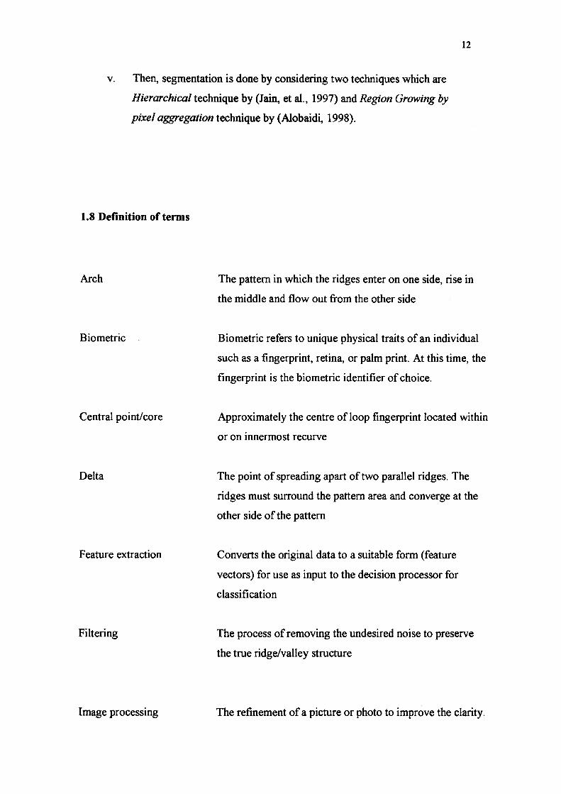
1.8 Definition of terms
Arch The pattern in which the ridges enter on one side, rise in
the middle and flow out from the other side
Biometric Biometric refers to unique physical traits of an individual
such as a fingerprint, retina, or palm print. At this time, the
fingerprint is the biometric identifier of choice.
Central point/core Approximately the centre of loop fingerprint located within
or on innermost recurve
Delta The point of spreading apart of two parallel ridges. The
ridges must surround the pattern area and converge at the
other side of the pattern
Feature extraction Converts the original data to a suitable form (feature
vectors) for use as input to the decision processor for
classification
Filtering The process of removing the undesired noise to preserve
the true ridge/valley structure
Image processing The refinement of a picture or photo to improve the clarity.

Left loop
Minutiae
Pattern recognition
Ridge bifurcation
Ridge ending
Ridges/valleys
Right loop
Segmenting
Tented arch
It is used in image recognition and computer vision.
The pattern in which a ridge recurve (loop) to the left
angle, touching a line drawn from the delta to the central
point (same as right loop except to the left)
Specified term for ridge ending and ridge bifurcation
Consist of basically 3 phases which are data acquisition,
data pre-processing and decision classification
The point where a ridge forks or diverges into branch
ridges.
The end point of a ridge or the point where a ridge end
abruptly
Furrows on the surface of a fingertips
The pattern in which a ridge recurve (loop) to the right
angle, touching a line drawn from the delta to the central
point. There is exactly one delta in the pattern
The process of isolating between the foreground and the
background of the fingerprint image with the purpose to
identify the ridge line.
The pattern in which like the plain arch (normal arch),
except from that the ridges form a sharp angle (e.g. like a
tent) at the centre. There is no delta structure in arch and
tented arch

Thinning The process to extract and apply additional constraints on
the pixel elements that are to be preserved so that linear
structure of the input image will be recaptured without
destroying its connectivity.
Whorl The pattern in which contains at least two deltas and one
recurving ridge such as a spiral or a variation of a circle
1.9 Summary
Chapter II explains the review of literature about what have been done by the
previous authors considering fingerprint recognition and conclude about the desired
approaches of segmentation, which is applied in the research. In terms of certain
algorithm to extract features, pre-processing stage is undertaken.
BIBLIOGRAPHY
Alobaidi, B. M. K. (1998) “Fingerprint Image Enhancement.” Faculty of Computer
Science & Information System, University Of Technology Malaysia (UTM):
Thesis MSc.
Amengual, J.C., Juan, A., Perez, J.C., Prat, F., Saez, S., and Vilar, J.M., 1997. “Real
time Minutiae Extraction in Fingerprint Images ” 6th International Conference
on Publication, Vol. 2, pp. 871 - 875.
Azmi, Kamis. (2000) “Pengecaman Cap Jari: Peningkatan Kualiti Imej” Faculty of
Computer Science & Information System University Of Technology
Malaysia (UTM) : Thesis BSc.
Bowen, J. D. 1992. “Automatic Fingerprint Pattern Classification Using Neural
Networks.” DEE Colloquium on Neural Network for Image Processing
Applications (Digest No. 186).
Dzulkifli, Mohamad. (1997) “The Identification of Trademark Symbols based on
Modeling Techniques” Faculty of Computer Science & Information System,
University Of Technology Malaysia (UTM): Thesis Phd.
Halici, U., and Ongun, G. 1996. “Fingerprint Classification Through Self Organizing
Feature Map Modified to Treat Uncertainties.” Proceedings of the IEEE 84,
no. 10, pp. 1497-1512.
Hughes, P. A., and Green, A. D. P. 1991. "The Use Of Neural Networks For
Fingerprint Classification." IEEE 2nd International Conference on Artificial
Neural Networks pp. 79-81.
Hussain, Z. (1991) “Digital Image Processing : Practical Applications of Parallel
Processing Techniques.” Ellis Horwood Limited, USA.
Jain, A. K., Hong, L., Pankanti, S., and Bolle, R. 1997. “An Identity - Authentication
System Using Fingerprint .” Proceedings of the IEEE. Vol. 85, No. 9, pp.
1365- 1388.
Kamijo, M. 1993. “Classifying Fingerprint Images Using Neural Network : Deriving
the Classification State.” IEEE International Conference of Neural Network
3, pp. 1932- 1937.
Kasaei, S., Deriche, M., and Boashash, B. 1997. “Fingerprint Feature Extraction
Using Block-Direction On Reconstructed Images.” IEEE Tencon of Speech
Technologies for Computing & Telecommunication, pp. 303 - 306.
Kasaei, S., Deriche, M., and Boashash, B. 1997. “Fingerprint Feature Enhancement
Using Block-Direction On Reconstructed Images.” 1st IEEE International
Conference on Communication & Signal Processing, ICICS ‘97, pp. 721 -
725.
Maio, D., and Maltoni, D. 1996. “A Structural Approach to Fingerprint
Classification.” Proceedings of 13th International Conference on Pattern
Recognition, Vol. 3, pp. 578 - 585.
Moscinska, K., and Tyma, G. 1993. “Neural Network Based Fingerprint
Classification.” Proc. Of EEE 3rd International Conference On Neural
Network, pp. 229 - 232.
Myler, Harler, R., and Weeks, Arthur, R. (1993) “The Pocket Handbook Of Image
processing Algorithms In C.” Prentice H all: Englewood Cliffs, New Jersey.
Ratha, N. K., Karu, K., Chen, S., and Jain, A. K. 1996. “A Real-Time Matching
System For Large Fingerprint Databases.” IEEE Transactions on Pattern
Analysis and Machine Intelligence 18, no. 8, pp. 799 - 813.

Uchida, K., Kamei, T., Mizoguchi, M., and Temma, T. 1998. “Fingerprint Card
Classification with Statistical feature Integration.” Proceedings 14th
International Conference Pattern recognition 2, pp. 1833 - 1839.
Umbaugh, Scott, E. (1998) “Computer Vision and Image Processing : A Practical
Approach Using CVIPtooIs (International Edition).” Prentice-Hall
International, Inc., USA.
Xiao, Q., and Raafat, H., 1990. “A Combined Statistical and Structural Approach For
Fingerprint Image Postprocessing”. IEEE Transaction, pp. 331 - 335.

10
11
12
13
14
15
16
17
PROJECT I
23 Preliminary study
E3 Literature review and data collection
£■! Writing the proposal (Project I)
EH Presentation of the proposal
PROJECT II
s/ Analyze possible segmentation technique a
>/’ Preparation of image samples
Design & Coding
V Build a system prototype
V Implementation - processing code with sarr
E i Testing and evaluation
V Write-up thesis draft
V Presentation for Project II
V Modification of the draft
- / Submit thesis
98 days Mon 12/6/99 Tue 3/28/00
19 days Mon 12/6/99 Mon 12/27/99
54 days Tue 12/28/99
Wed 3/1/00
V
22 days
2 days Mon 3/27/00
Mon 2/28/00
Sat 3/25/00
Tue 3/28/00
55 days
3 days
3 days
20 days
5 days
5 days
4 days
9 days
1 day
3 days
1 day
Wed 3/29/00
Wed 3/29/00
Sat 4/1/00
Wed 4/5/00
Sat 4/29/00
Fri 5/5/00
Thu 5/11/00
Tue 5/16/00
Fri 5/26/00
Sat 5/27/00
Wed 5/31/00
Wed 5/31/00
Fri 3/31/00
Tue 4/4/00
Thu 4/27/00
Thu 5/4/00
Wed 5/10/00
Mon 5/15/00
Thu 5/25/00
Fri 5/26/00
Tue 5/30/00
Wed 5/31/00
Project: Proposal Date: Thu 6/1/00
Task
Split
Progress
Milestone
i l;!®i ITi Summary
Rolled Up Task
Rolled Up Split
Rolled Up Milestone <(y>
Rolled Up Progress
External Tasks
Project Summary
69
Rolled Up Task
Rolled Up Split
Rolled Up Milestone <Q>
69
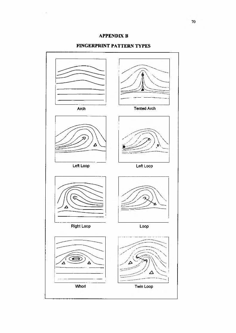
APPENDIX B
FINGERPRINT PATTERN TYPES
Arch Tented Arch
^ 8 ^
' • / \ \ \ y ' ' / / ' C' 1 \ \
, / y y j ) \ \ ®V-___
Left Loop Left Loop
V — -— ~ ~ ~ r ~r.....
Right Loop Loop

APPENDIX C
ORIGINAL SIZE OF FINGERPRINT IMAGE SCANNED THROUGH
BIOMETRICS-SCANNER VERIDICOM PASSPRINT ( 300 x 300 PIXEL )
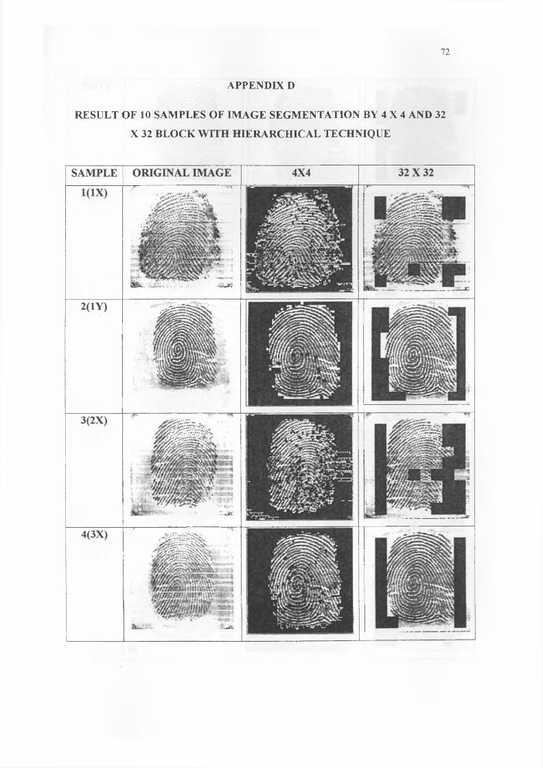
APPENDIX D
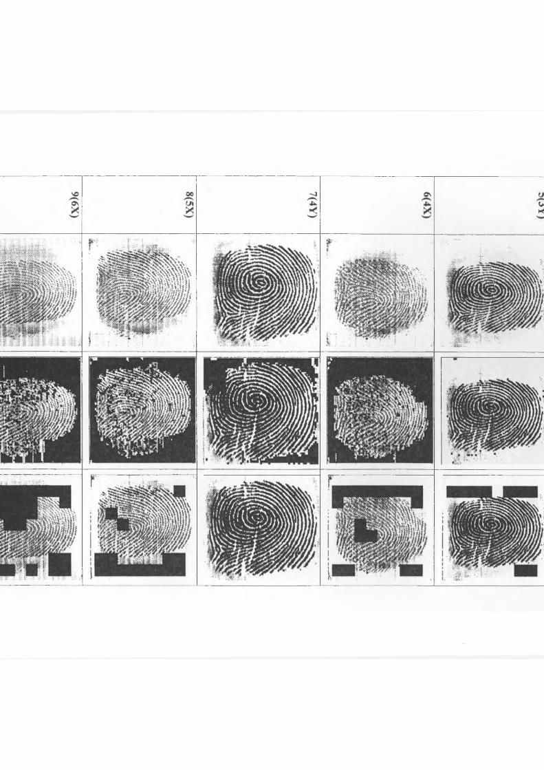
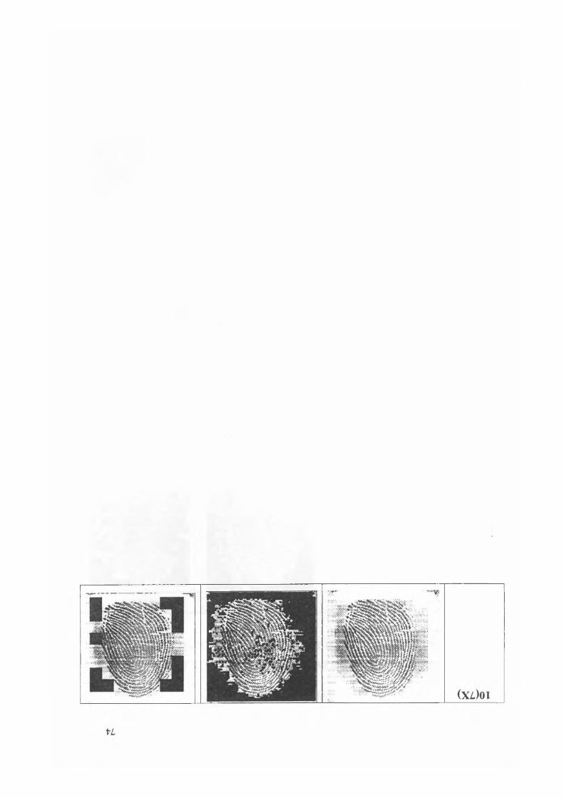
APPENDIX E
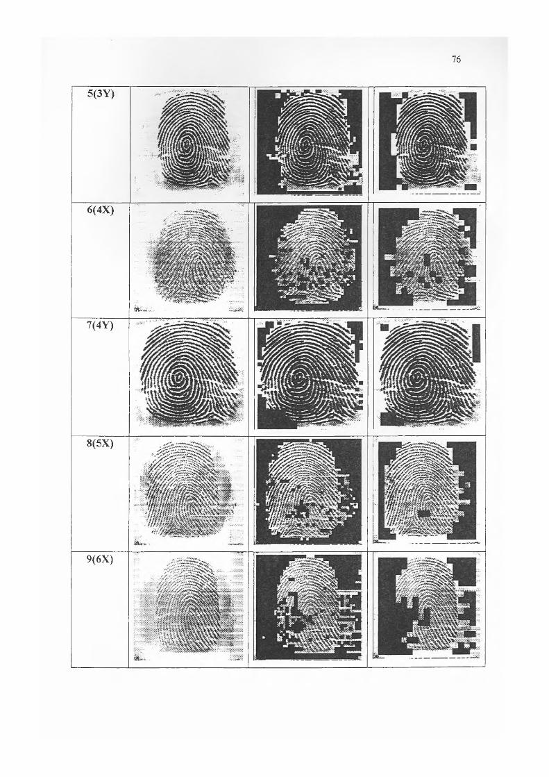
5(3Y)
6(4X)
&v.~.
7(4 Y)
8(5X)
9(6X)

LL
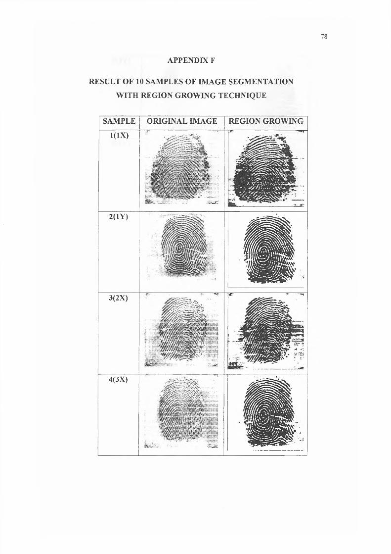
APPENDIX F
SAMPLE ORIGINAL IMAGE REGION GROWING
1(1X)
1! r?
j
2(1Y)
c
3(2X) C? • *1
4(3X)
H
5(3Y)
I P S
•VWt
P .JM& -:.0 ^y :;v :«
6(4X) .'s: :
£&V<.. • • ’.1
7(4Y)
®
"" "
8(5X)
iiii' sF ^ ^ w Ib
i " - ' ^9(6X)
......—

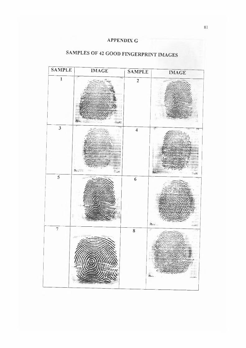
APPENDIX G
SAMPLES OF 42 GOOD FINGERPRINT IMAGES
SAMPLE IMAGE SAMPLE IMAGEI . • ><v. ... >jf> 2
f t
3 1 • •• • v<
. J J U f c
id * ' * 1
4
15 6
7
I I I
8
| 1 -
j w . v x * X .;

19 20
1 '/$ |
21
:• if* •'
22
23 24, r~-"’s'<vUCV vNiV'ot' V" ’’■,''.'**'*oi'*«w£ >y -.<;:
25 ;
•,.. jfs: .y r?:,gj*& >•■ ?. ' v
26
I ^ S 1 |
27•/4'-"• i'-.'-.;\.»Sy •;,
28:, i i t S P i i .
I p t t l i l t
;.;'.;v\_. . . . .. ' .WX
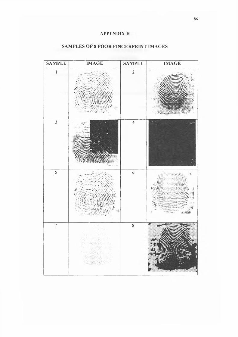
APPENDIX H
SAMPLES OF 8 POOR FINGERPRINT IMAGES
SAMPLE IMAGE SAMPLE IMAGE
1v-• v • A. / *• \ %>■.
/ » .?v:V-v- ?:> S:x>->AVv
• ., • . . : v - y / 5 i J >5 * %. - :•;:>::
2•■i. ^ h - y^v/1. Av./a-Xv . -V . * • t *- ■
^ ^ l V"* « • • ***&*'• • V * / w- / • f
3
[
:•: .. .Xv.
4
1
5... •' w.v‘..*-v;'•v*:v’ ■*.*
■ ; vN\\\VVV/sJ&S'Z&X-:>>SSr\ >! >}'• »;
! V T>a> ' •* • ■'• '• - V•\ ' ■; f«.?Ays. * • *&.,;c ■
6 iVV\x. *
' »\\V.
'• , - * • ~V;?T?5fc ::l
■<V: 0 $
7 8 * * * '
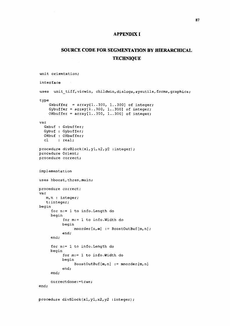
APPENDIX I
SOURCE CODE FOR SEGMENTATION BY HIERARCHICAL
TECHNIQUE
unit orientation;
interface
uses unit_tiff,vicwin, childwin,dialogs,sysutils,forms,graphics;
typeGxbuffer = array[1..300, 1..300] of integer;Gybuffer = array[l..300, 1..300] of integer;ORbuffer = array[1..300, 1..300] of integer;
varGxbuf : Gxbuffer;Gybuf : Gybuffer;ORbuf : ORbuffer; cl : real;
procedure divBlock(xl,yl,x2, y2 :integer); procedure Orient; procedure correct;
implementation
uses hboost,thres,main;
procedure correct; var
m,n : integer; t :integer;
beginfor n:= 1 to info.Length do begin
for m:= 1 to info.Width do begin
mnorder[n,m] := BoostOutBuf[m,n];end;
end;
for n:= 1 to info.Length do begin
for m:= 1 to info.Width do begin
BoostOutBuf[m,n] := mnorderfm,n]end;
end;
correctdone:=true;end;
procedure divBlock(xl,yl,x2,y2 rinteger);

varthetadeg,deg2, z m, n, gx, gyu, v, x, y countml, m2, nl, n2i , jvx,vy, ve
// cl
beginvx :=0; vy := 0; ve := 0; count :=1; ml := xl; m2 := x2; nl := yl; n2 := y2;
i : =0; j :=0;
for n := nl to n2 do //baca piksel 16x16begin
j : = j + l ;for m := ml to m2 do {kira Gradient Gx dan Gy) begin
i:=i+l;gx := (BoostOutBuf[m-1,n+1]) + 2*(BoostOutBuf[m,n+l])
+ (BoostOutBuf[m+1,n+1]);gx := gx - (BoostOutBuf[m-1,n-1] +
2* (BoostOutBuf[m,n-1]) + BoostOutBuf[m+1,n-1]);
gy := (BoostOutBuf[m+1,n-1] + 2 * (BoostOutBuf[m+1,n])+ BoostOutBuf[m+1,n+1]);
gy := gy - (BoostOutBuf[m-1,n-1] + 2 * (BoostOutBuf[m- l,n]) + BoostOutBuf[m-1,n+1]);
GxBuf[i,j] := gx;GyBuf[i,j] := gy;
end; i : =1;
end;
for v := 1 to blok do begin
for u:= 1 to blok do begin
vx := vx + (2 * gxbuf[u,v] * gybuf[u,v]); vy := vy + (sqr(gxbuf[u,v]) - sqr(gybuf[u, v])) ;
ve := ve + (sqr(gxbuf[u,v]) + sqr(gybuf[u,v]));end;
end;
if ve<>0 then begin
cl := sqrt ((sqr(vx) + sqr(vy))/(ve * blok * blok));
: real;: real;: integer;: integer;: integer;: integer;: integer;: real;
: real;
end else cl := 0;
{for n := nl to n2 do begin
for m := ml to m2 do begin
if cl < thresholdvalue then begin
BoostOutBuf[m,n] := 255;
setpixelcolor(TMDIChild(MainForm.ActiveMDIChild).Vicimage,m,n,0); end;
end;end;
)//mainform.Memol.Lines.Add(floattostr(cl));
if vy<>0 then begin
theta := 0.5 * arctan(vx/vy); deg := 180.0 / 3.142 * theta; if (deg < 0) and (deg >=-180) then begin
deg := deg + 180;end;
end;
if vy=0 then begin
theta:=0;end
else if vy > 0 then begin
theta := theta + 3.142;end
else if vx > 0 then begin
theta := theta + (3.142/2);end
else if vy < 0 then begin
theta := theta + (3.142/2);endelse
theta := theta;
with TMDIChild(MainForm.ActiveMDIChild).image6.Canvas do begin
pen.Width:=2;pen.Color:=clred;x := trunc(hipo * cos(theta));y := truncfhipo * sin(theta));moveto(ml+(blok div 2)+x,nl+(blok div 2)—y );lineto(ml+(blok div 2)-x,nl+(blok div 2)+y);
end;
with TMDIChild(MainFom.ActiveMDIChild) .image5.Canvas do begin
pen.Width:*2; pen.Color:*clred;
cos (theta) ) ; y := trunc(hipo * sin(theta)); m o v e t O d i V 2) +x,nl+ (blok div 2)-y); lineto(ml+(blok div 2)-x,nl+(blok div 2)+y);
end;end;
procedure Orient; var
xblock, xbal, yblock, ybal :integer; xcount, ycount :integer; xl,yl :integer;
beginyblock:=info.Length div blok; ybal:=info.Length mod blok; xblock:=info.width div blok; xbal:=info.width mod blok;
//mainform.Memol.Lines.Add ('length : 1+inttostr(info.Length));//mainform.Memol.Lines.Add //mainform.Memol.Lines .Add //mainform.Memol.Lines.Add //mainform.Memol.Lines.Add //mainform.Memol.Lines.Add
xl:=l;yi:=l;
('width : '+inttostr(info.width) ('xblock : '+inttostr(xblock)) ; ('xbal : '+inttostr(xbal)); (’yblock : '+inttostr(yblock)); ('ybal : '+inttostr(ybal));
do
for ycount:=1 to yblock do begin
for xcount:=1 to xblock do begin
with TMDIChild(MainForm.ActiveMDIChild).image2.canvas
begin//pen.Color:=clblue;//rectangle(xl,yl,xl+16,yl+16);//pen.Color:=clblue;//Pixels[xl+8,yl+8]:=clblue; divBlock(xl,yl,xl+blok,yl+blok);
end;xl:=blok*xcount;
end;
xl:=1;yl:=blok*ycount;
end;
end;
end.

APPENDIX J
SOURCE CODE FOR SEGMENTATION BY REGION GROWING BY
PIXEL AGGREGATION TECHNIQUE
unit region_grow;
interface
uses sysutils, unit_tiff, main, childwin, vicwin, math,Windows, Messages, Classes, Graphics, Controls, Forms, Dialogs, StdCtrls;
//uses sysutils, unit_tiff, main, childwin, vicwin, math;
constxseed =3 0 ; yseed = 30;
typeinbuffer = array[1..600, 1..600] of integer; outbuffer = array[1..600, 1..600] of integer;GrayLevel = array[0..255] of integer;
procedure RegionGrowing(name : string); procedure growfx, y, threshold :integer); procedure Bacalmej(Vicimage : imgdes); procedure BacaMedian(Vicimage : imgdes); procedure BacaHPass(Vicimage : imgdes); procedure BacaHBoost(Vicimage : imgdes); procedure BacaAdaptive(Vicimage : imgdes); procedure DisplaySegment;function IntToBinary(value, digit:integer):integer; procedure RGData;
varRGinbuf : inbuffer;RGoutbuf: outbuffer; total, count : integer;Nl, Ml : integer;N2, M2 : integer;GV : GrayLevel; fb : textfile; threshold : integer; threshvalue : integer;
implementation //Region Growing
uses median, hpass, hboost, adaptive, histo_grow;
procedure RegionGrowing(name : string); var
x, endx, y, endy : integer; threslnput : string;
beginNl := 0; Ml := 0;

N2 := width; M2 := height; endx := N2-1; endy := M2-1;
// xseed := 50; yseed := 50;
// threslnput := InputBox('Region Growing1, 'Enter Threshold Value', threslnput);// threshold := strtoint(threslnput);
for y := 1 to endy do for x := 1 to endx do RGoutbuf[y][x] := 1;
total := 0; count := 0; for y := yseed - 5 to yseed + 5 do
for x := xseed - 5 to xseed + 5 doif ((x>l) and (y>l) and (x<endx) and (y<endy)) then begin
count := count + 1; total := total + RGinbuf[y][x];
end;grow (xseed, yseed, threshold);
DisplaySegment;
end;
procedure grow (x, y, threshold : integer); var
diff, mean : real;
beginif RGoutbuf[y][x] = 1 then begin
mean := total/count; diff := RGinbuf[y][x] - mean; if (diff < 0) then
diff := -diff;
if (diff < threshold) then begin
total := total + RGinbuf[y][x]; count := count + 1;RGoutbuf[y][x] := 0 ;
if (x = 3) and (y = 1) then begin
for y := Ml+1 to M2-1 do begin
for x : = Nl+1 to N2-1 do begin
if RGoutbuf[y][x] = 1 then begin
mean := total/count;diff := RGinbuf[y][x] - mean;
if (diff < 0) then diff := -diff;
if (diff < threshold) then begin
total := total + RGinbuf[y][x]; count : = count + 1;RGoutbuf[y][x] := 0;
mean := total/count; end;
end; end; end; exit;
end;
if (x > 1) thengrow(x-l, y, threshold);
if (y > 1) thengrow(x, y-1, threshold);
end;end;
end;
procedure Bacalmej(Vicimage : imgdes); vari, j, y : integer;
beginfor i := 1 to Info.Length do
beginfor j := 1 to Info.Width do
beginy := TDatafi]A [j] ;RGinbuf[i][j] := y;
end;end;
end;
procedure BacaMedian(Vicimage : imgdes) vari, j, y : integer;
beginfor i := 1 to Info.Length do
beginfor j := 1 to Info.Width do
beginy := MedOutBuf[i][j] ; RGinbuf[i][j] := y;
end;end;
end;
procedure BacaHPass(Vicimage : imgdes); vari, j, y : integer;
beginfor i := 1 to Info.Length do
beginfor j := 1 to Info.Width do begin
y := PassOutBuf[i][j] ; RGinbuf[i][j] := y;
end;end;
end;
procedure BacaHBoost(Vicimage : imgdes) vari, j, y : integer;
beginfor i := 1 to Info.Length do begin
for j := 1 to Info.Width do begin
y := BoostOutBuf[i][j] ;RGinbuf[i][j] := y;
end;end;
end;
procedure BacaAdaptive(Vicimage : imgdes); vari, j, y : integer;
beginfor i := 1 to Info.Length do begin
for j := 1 to Info.Width do begin
y := AdapOutBuf[i][j] ;RGinbuf[i][j] := y;
end;end;
end;
procedure DisplaySegment; var
i, j : integer; begin
for i := 1 to Info.Length do begin
for j := 1 to Info.Width do begin
if RGoutbuf[i][j] = 0 then begin
RGoutbuf[i][j] := 255;
setpixelcolor(TMDIChild(MainForm.ActiveMDIChild) .Vicimage,j , i, 255); end
elseif RGoutbuf[i][j] = 1 then begin
RGoutbuf[i][j] := 0;
setpixelcolor(TMDIChild(MainForm.ActiveMDIChild).Vicimage,j,i,0); end;
end;TMDIChild(MainForm.ActiveMDIChild).imagel.refresh;
end;RGData;
end;
| CHECK DATAjprocedure RGData; var
i, j, k : Integer; begin
AssignFile(fb, 'c:\RG_data.txt');Rewrite(fb);

k:= 0;for i:= 1 to Info.Length do begin
for j:= 1 to Info.Width do begin
if k * Info.Width then begin
Writeln (fb, IntToBinary(RGOutBuf[i][j],1)); k:= 0;
endelse
Write (fb, IntToBinary(RGOutBuf[i][j],1)); k:= k + 1;
end;end;Writeln(fb);Writeln(fb, 'End Of Text1);CloseFile(fb);
end;{ ***************+*+++***** BINARY FUNCTION
function IntToBinary(value, digit:integer):integer; begin
case value of0 : IntToBinary := 1;255 : IntToBinary := 0;
end;end;
end.