Embed Size (px)
Citation preview

Finishing and Improving of Finger Vein SystemTrethyn Trethyn
Electrical Engineering Bachelor Student
Abstract—Finger vein biometrics is a developing field, cur-rently dominated by commercial research. Since commercialproducts and research are kept private, the academic communitywishes to develop their own finger vein biometric systems, inorder to conduct their own research. This report details aredesign of the finger vein scanner system at the University ofTwente, making the system self contained and more coherent. Thesystem consists of a strip of individually controllable Near In-fraRed (NIR) LEDs, an InfraRed (IR) camera, a custom designeddriver board to provide power to the LEDs and a RaspberryPi 4 for control. The redesign is done by migrating the userinteraction, signal processing, matching and enrolment systemsfrom MatLab running on an external computer to a combinationof OpenCV and C++, running directly on the finger vein scanner.The redesign also includes a new implementation of automaticLED adjustment, in order that the finger being captured iscorrectly exposed and can be properly processed. Furthermoretouchscreen control is implemented for the system, making itcompletely standalone. The performance of the migrated systemwas evaluated with respect to the original, and vein extractionand recognition were found to be comparable.
Index Terms—Near InfraRed(NIR), Finger Vein, OpenCV,C++, LED
I. INTRODUCTION
There are several forms of biometric identification currentlyin common use. Fingerprint sensors on phones and computers,face recognition and retinal scans. There are, however, manymore unique identifiers humans carry as a part of their body,such as the patterns of veins inside fingers.
Finger vein biometric devices do exist, but much lesscommonly than other forms of biometric recognition. Thereare a few on the commercial market, such as the HitachiVeinID [1], but since these are commercial and hence theinformation on their systems private, scientific research intofinger vein biometrics must be done separately. To this end,the University of Twente currently has a finger vein scannerdevice. However, the device’s functionality could be improved.As of this writing it requires connectivity to a computer inorder to capture images, or display those images, and allimage processing and matching is currently done completelyremotely, via Matlab. This is a nonideal situation, the device isnot exactly easily usable in this state, so this text will describean attempt to properly integrate the functionality of the deviceall in one physical setup, with the addition of a touchscreenfor control.
II. RELATED WORK
A. Finger Vein Recognition
Finger vein recognition is a member of the larger groupof vascular biometric techniques, which includes hand, finger,
wrist and eye recognition based on the unique patterns of bloodvessels within these body parts [2]. As might be guessed fromthe name, finger vein recognition is specifically concerning theblood vessels in fingers.
The vascular patterns in fingers are measured by means ofNear InfraRed (NIR) light, which is absorbed by haemoglobin[2]. When the area of interest is illuminated with NIR light,images captured with an NIR sensitive camera will show areascontaining haemoglobin as dark, and other areas as light,allowing noninvasive capture of the vascular pattern of thefinger [2] [3] [4].
There are multiple methods which have been used to capturefinger vein images, namely transmission, reflection and sideillumination [4] [2]. In transmission, NIR illumination isprovided above the finger, which then shines through thefinger and to a camera positioned below it [4]. In reflection,the illumination is provided below the finger along with thecamera. This has an advantage over transmission, in that theuser can see their finger while using the device and thus feelsmore comfortable [4], but also the disadvantage that mostof the captured light does not penetrate the skin, leading tolow contrast between veins and surrounding finger [4]. Lastlycomes side illumination, in which light sources are placedon one or both sides of the finger, with camera below. Thelight would scatter inside the finger and the camera wouldpick up some of that scattered light [4] [5]. This method hasthe psychological advantage of a visible user finger, and thedisadvantage that the side(s) of the user’s finger will be overexposed [4].
Once the vascular pattern images have been captured, theythen need to be processed and identified. The images areusually preprocessed, in order to combat factors such as bluror poor contrast [3] [2]. Then, once the images have been en-hanced, the region of interest (finger area) must be determined.There are several different ways to do this, often involving thedetection of some component with known position relative tothe rest of the finger (e.g. edge detection) [3] [2]. Finally, thenthe pattern of veins can be extracted. There are many ways thisis done, including Repeated Line Tracking, which tracks darklines, the Gabor Filter, which performs texture analysis, or theuse of trained Neural Networks to recognise vein patterns [6].
Finally, now that the vein pattern has been isolated, thevein images need to be matched and identified. Biometriccomparison is done by use of algorithms which compare theimages to images in a database and look for the best match(es)in terms of multiple parameters represented as comparisonscores [3] [2].
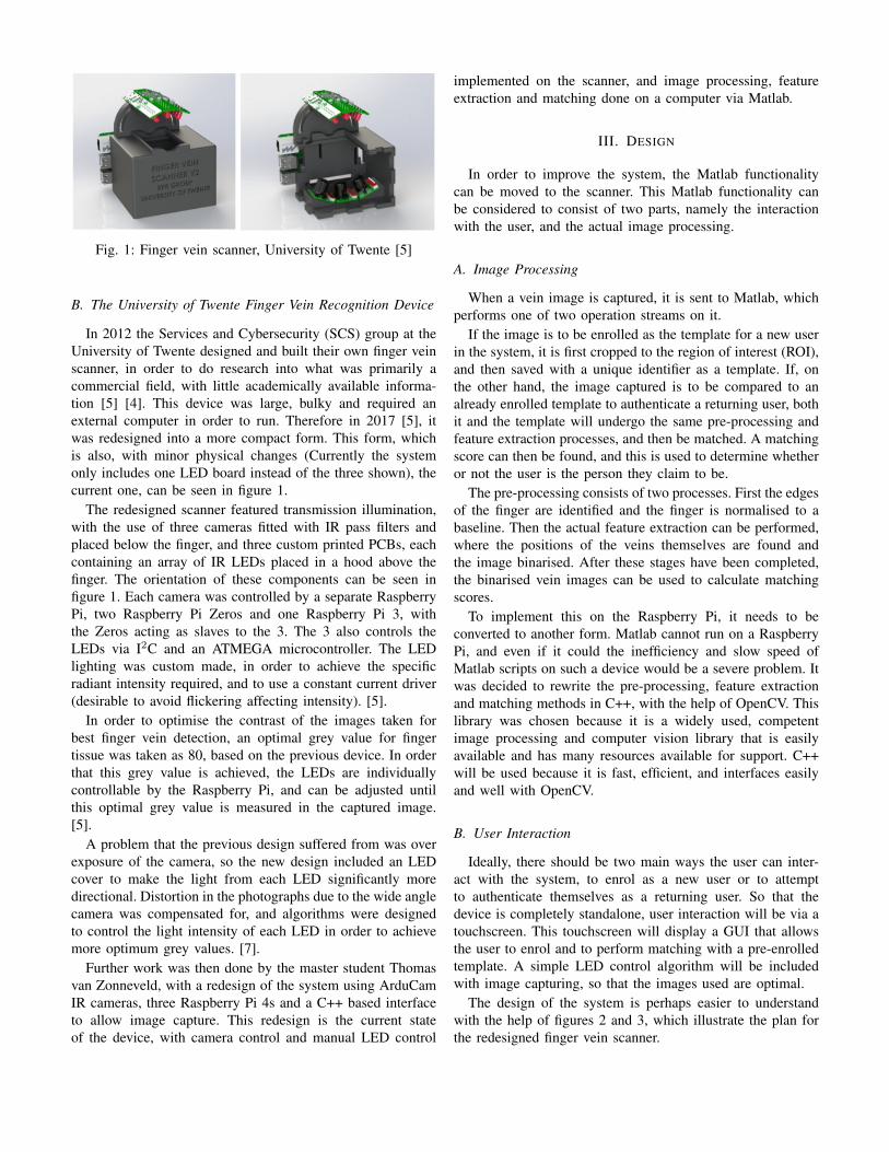
Fig. 1: Finger vein scanner, University of Twente [5]
B. The University of Twente Finger Vein Recognition Device
In 2012 the Services and Cybersecurity (SCS) group at theUniversity of Twente designed and built their own finger veinscanner, in order to do research into what was primarily acommercial field, with little academically available informa-tion [5] [4]. This device was large, bulky and required anexternal computer in order to run. Therefore in 2017 [5], itwas redesigned into a more compact form. This form, whichis also, with minor physical changes (Currently the systemonly includes one LED board instead of the three shown), thecurrent one, can be seen in figure 1.
The redesigned scanner featured transmission illumination,with the use of three cameras fitted with IR pass filters andplaced below the finger, and three custom printed PCBs, eachcontaining an array of IR LEDs placed in a hood above thefinger. The orientation of these components can be seen infigure 1. Each camera was controlled by a separate RaspberryPi, two Raspberry Pi Zeros and one Raspberry Pi 3, withthe Zeros acting as slaves to the 3. The 3 also controls theLEDs via I2C and an ATMEGA microcontroller. The LEDlighting was custom made, in order to achieve the specificradiant intensity required, and to use a constant current driver(desirable to avoid flickering affecting intensity). [5].
In order to optimise the contrast of the images taken forbest finger vein detection, an optimal grey value for fingertissue was taken as 80, based on the previous device. In orderthat this grey value is achieved, the LEDs are individuallycontrollable by the Raspberry Pi, and can be adjusted untilthis optimal grey value is measured in the captured image.[5].
A problem that the previous design suffered from was overexposure of the camera, so the new design included an LEDcover to make the light from each LED significantly moredirectional. Distortion in the photographs due to the wide anglecamera was compensated for, and algorithms were designedto control the light intensity of each LED in order to achievemore optimum grey values. [7].
Further work was then done by the master student Thomasvan Zonneveld, with a redesign of the system using ArduCamIR cameras, three Raspberry Pi 4s and a C++ based interfaceto allow image capture. This redesign is the current stateof the device, with camera control and manual LED control
implemented on the scanner, and image processing, featureextraction and matching done on a computer via Matlab.
III. DESIGN
In order to improve the system, the Matlab functionalitycan be moved to the scanner. This Matlab functionality canbe considered to consist of two parts, namely the interactionwith the user, and the actual image processing.
A. Image Processing
When a vein image is captured, it is sent to Matlab, whichperforms one of two operation streams on it.
If the image is to be enrolled as the template for a new userin the system, it is first cropped to the region of interest (ROI),and then saved with a unique identifier as a template. If, onthe other hand, the image captured is to be compared to analready enrolled template to authenticate a returning user, bothit and the template will undergo the same pre-processing andfeature extraction processes, and then be matched. A matchingscore can then be found, and this is used to determine whetheror not the user is the person they claim to be.
The pre-processing consists of two processes. First the edgesof the finger are identified and the finger is normalised to abaseline. Then the actual feature extraction can be performed,where the positions of the veins themselves are found andthe image binarised. After these stages have been completed,the binarised vein images can be used to calculate matchingscores.
To implement this on the Raspberry Pi, it needs to beconverted to another form. Matlab cannot run on a RaspberryPi, and even if it could the inefficiency and slow speed ofMatlab scripts on such a device would be a severe problem. Itwas decided to rewrite the pre-processing, feature extractionand matching methods in C++, with the help of OpenCV. Thislibrary was chosen because it is a widely used, competentimage processing and computer vision library that is easilyavailable and has many resources available for support. C++will be used because it is fast, efficient, and interfaces easilyand well with OpenCV.
B. User Interaction
Ideally, there should be two main ways the user can inter-act with the system, to enrol as a new user or to attemptto authenticate themselves as a returning user. So that thedevice is completely standalone, user interaction will be via atouchscreen. This touchscreen will display a GUI that allowsthe user to enrol and to perform matching with a pre-enrolledtemplate. A simple LED control algorithm will be includedwith image capturing, so that the images used are optimal.
The design of the system is perhaps easier to understandwith the help of figures 2 and 3, which illustrate the plan forthe redesigned finger vein scanner.

Fig. 2: Hardware Design Diagram (fullsize version in ap-pendix)
Fig. 3: Software Design Diagram (fullsize version in appendix)
C. Hardware
For the purpose of these improvements, not many physicalchanges need to be made, with hardware additions mostlyconsisting of the addition of a touchscreen. Of the optionsavailable from the lab, it was decided to use the Adafruit 2.4”PiTFT Hat [8]. This decision was made because this screen isof a useful size where the information and options required canbe neatly displayed, and because it does not interfere with theoperation of I2C. The other available screen was both largerand considerably dirtier, with its signals interfering with theI2C bus and hence the LED and camera control.
D. Evaluation
It is all very well to design a system, but that design does notmatter very much unless it works. The new integrated fingervein scanner should perform at least as well as the previousversion, with equivalent or better finger recognition and imagecapturing.
Finger recognition performance can be evaluated and com-pared by performing image processing and matching on thesame images with both implementations, then comparing theresults. There should not be a loss of matching accuracy,and vein images generated should be of sufficient quality toprovide useful results.
Image capture performance can be evaluated by ensuringthat the finger vein images captured are of a good qualityto be used. Based on previous iterations of the scanner, andinformation from previous work, the finger itself should beuniformly at an acceptable grey value, and the veins shouldbe reliably extractable [5] [7].
IV. METHOD
Now that plans have been laid, the improvement and inte-gration of the device can be performed.
A. Pre-processing, Feature Extraction and Matching
In the original Matlab, the finger region identification, imagenormalisation, vein extraction, binariasation and matchingwere split into separate functions. No reason was seen tochange this, so the titles and usages were carried over to theC++ implementation.
1) Region identification: Called lee region, this function isbased on the region detection method described in a paperby Lee et al. [9]. It works by convolving the image with the4x40 mask shown in equation 1, splitting the image in halfvertically, and then taking the maximum point in each columnof the upper half, and the minimum in each column of thelower half, to be the edges of the finger. No major changeswere made in the working of this function during its linguisticmigration, and any differences in output between the versionsare expected to be due to differences in filter implementationbetween OpenCV’s Filter2D and MatLab’s imfilter.
−1 −1 −1 ... −1−1 −1 −1 ... −11 1 1 ... 11 1 1 ... 1
(1)
2) Image normalisation: This function is calledhuang normalise, and is based on the normalisationmethod in a paper by Huang et al., though without the ellipticprojection described there [10]. The transform matrix differsslightly in appearance between the implementations, due todifferent conventions for it between Matlab and OpenCV. Thebaseline projection is also different, since in Matlab a baselineis determined using robustfit, in the C++ implementation aself written implementation of least squares linear regressionis used, named linfit. They produce similar, but not identicalresults.
3) Vein extraction: The function used for vein extractionis called miura max curvature, and is based on a methoddescribed in the paper by Miura et al. [11]. Vein patterns areidentified by filtering the normalised image with five differentkernels, determined according to equations based on an inputparameter sigma. These filtered results are then combinedinto four images. Each image shows changes between lightand dark in the original image, though sensitive in differentdirections. One shows horizontal changes, one vertical, onetop left to bottom right diagonal, one bottom left to top rightdiagonal. These images are multiplied with the binary fingerregion mask obtained in lee region, and then each of theseimages is then scanned over, each curve being used to markone point on the vein image. These points are in the placeof maximum curvature, and weighted by the length of thecurve. Once all points have been found and weighted, veins areisolated by finding vein centres. The main difference betweenthe C++ and Matlab implementations of this function is in thetreatment of the bottom left to top right diagonal curvature

extraction. OpenCV has a function which is used to finddiagonals of matrices, so to use this the image in questionis flipped over the vertical axis before diagonal extraction.
4) Binarisation: Once this vein image has been generated,it is binarised. In both languages this is done by finding themedian value of the non zero parts of the image and usingthis as a threshold for binarisation.
5) Matching: The matching function, named miura matchand once again based on the paper by Miura et al. [11].Matching is performed quite simply by finding the crosscorrelation of the template image and the input image, takingthe maximum result and then normalising over a specified atinput search area. The result of this will be a score between 0and 0.5. This is multiplied by 200 when output to the user, soit can be represented as a percentage. The main differencesbetween the two implementations of this function are inMatlab and OpenCV’s approaches to cross correlation, whichare unlikely to produce exactly the same results. The imagehad to be manually zero padded in the C++ implementation,while Matlab does this implicitly.
B. Touchscreen and User Interaction
Since one of the main ideas of this project is to make thefinger vein scanner standalone, all interaction with the systemwill now have to be via the touchscreen that will be installed.
1) Physical implementation of the touchscreen: The touch-screen used was designed as a Raspberry Pi hat [8]. As such,although it only makes use of the SPI pins [8], it is providedwith a full header to sit on top of the Raspberry Pi board.The screen does provide an access point for 26 out of 40 pinswhich it does not use. A problem with this is that in the currentdesign the header of the Pi is already in use, being entirelyconnected to the LED driver board. However, in practice onlythe I2C, 5 V and GND pins are needed for the connectionto the driver board, so it should be possible to connect allthree devices at once. An attempt was made to run the screenremotely via jumper cables, but the screen then did not displayany information that was sent to it, so the system was changedso that the Pi and driver board were connected by jumpercables and the screen sat on top of the Pi. This did work,although not well since the jumper cables could not provideenough power to the Pi.
2) GUI for the touchscreen: As was described in sectionIII-B, the touchscreen GUI should be able to allow theenrolment of new users, and to authenticate returning usersagain by comparing their finger to a pre-enrolled template.The GUI that was designed and realised can be seen in figure4. The capture button allows for a new picture to be taken,enrolling a user in the system. The arrow buttons allow the listof saved images to be cycled through (current image will beshown in the rectangle on the right), and the identify buttonwill match the currently selected image to a finger presented tothe device, then report the score beneath the rectangle, as wellas display the identified vein pattern for interest. A previewshowing the direct information stream from the camera isdisplayed overlaying the GUI. This is done because of the way
Fig. 4: Final version of the finger vein scanner GUI
raw camera footage is handled by the Raspberry Pi - it’s donelow level by the GPU [12], and as such cannot be integratedwith the rest of the GUI, which is made with GTKmm 3 [13].A quit button is also included, so the user can escape to thedesktop if needed.
C. LED Control
In order that pictures taken with the device can be reliablyusable, a form of LED control was implemented. A simplecontrol function, adjust leds auto, was written. This functioncaptures an image with the camera, then runs lee region onthat image to identify the finger area. Then a rectangle onepixel wide and as long as the image is taken from the imageat the centre of the finger (based on the edge positions returnedby lee region). The mean grey value of this rectangle is thenfound, and if it is below the lower acceptable threshold of 70the lights are brightened by a step, while if it is above theupper acceptable threshold of 90 the lights are dimmed by astep. These acceptable thresholds were chosen based on themean grey values (as found by the same method as describedabove) for several images in the University of Twente’s fingervein dataset [4].
V. RESULTS
The image processing functions were tested first using veinimages from the University of Twente dataset [4], second withimages captured by the system itself. In order to determinethe quality of the system, tests were performed in which aselected finger vein image would be compared to a differentimage of the same finger, a different finger of the sameuser, and a completely unrelated finger. In order to compareimplementations of the system, these tests were performedwith the same images and the same comparisons in Matlaband in C++. Some of the vein images generated during thesetests can be seen in figure 6 (Matlab) and 7 (C++).

(a) Vein pattern used as tem-plate for testing
(b) Different image of samefinger as template
(c) Vein pattern from a differ-ent finger of the same user
(d) Vein pattern of a differentuser
Fig. 6: Resulting veins from Matlab finger vein comparison
These test sets were performed ten times, each time withdifferent sets of images. The results of these tests can be seensummarised in table I.
Then, in order to test the ability of the system to captureuseful images, a small dataset of three individuals was cap-tured anonymously, and the same tests were performed usingthese images. Due to the smaller size of this dataset, six sets oftests were performed rather than ten. Some of the vein imagescaptured can be seen in figures 8 and 9. The results of thissecond set of tests can be seen in table II. It would have beenpreferable for the sample size to be larger, but the number ofboth available and willing participants was somewhat limited.
An example of the images captured by the system can beseen in figure 5a.
(a) Finger image captured bythe new finger vein system
(b) Finger image captured bythe previous finger vein system
Fig. 5: Comparison of images from the previous and re-designed finger vein systems
(a) Vein pattern used as tem-plate for testing
(b) Different image of samefinger as template
(c) Vein pattern from a differ-ent finger of the same user
(d) Vein pattern of a differentuser
Fig. 7: Resulting veins from C++ finger vein comparison
(a) Vein pattern used as tem-plate for testing
(b) Different image of samefinger as template
(c) Vein pattern from a differ-ent finger of the same user
(d) Vein pattern of a differentuser
Fig. 8: Resulting veins from Matlab finger vein comparison ofimages captured with the device
(a) Vein pattern used as tem-plate for testing
(b) Different image of samefinger as template
(c) Vein pattern from a differ-ent finger of the same user
(d) Vein pattern of a differentuser
Fig. 9: Resulting veins from C++ finger vein comparison ofimages captured with the device

TABLE I: Results of implementation comparison performed on dataset images
Matching score self Matching score self, other finger Matching score otherName Matlab C++ Matlab C++ Matlab C++ Notes
0001 1 1 120509-135315 34.5 % 27.9 % 11.8 % 24.8 % 11.6 % 18.9 %0002 1 1 120509-140611 38.5 % 54.1 % 10.4 % 21.4 % 11.1 % 19.1 %0003 1 2 120509-141420 18 % 43 % 13.7 % 22.4 % 13.6 % 31.4 % Matlab
baselineextrapolationreachediteration limit
0004 1 2 120509-141934 24.2 % 30.6 % 10 % 26.9 % 13.4 % 26 % Matlabbaselineextrapolationreachediteration limit
0005 1 1 120509-142157 49 % 74.6 % 11.8 % 21.6 % 14.7 % 19.6 %0006 1 1 120509-143643 28.9 % 48.4 % 11.1 % 27.9 % 13 % 33 %0007 1 2 120509-144552 22.6 % 34.6 % 13.7 % 23.8 % 10 % 18.5 %0008 1 2 120509-145152 22 % 28.9 % 14.1 % 21.1 % 11.5 % 28 %0009 1 4 120523-144626 36.7 % 53.8 % 16 % 28.6 % 11.9 % 22.2 % Matlab
baselineextrapolationreachediteration limit
0010 1 2 120509-150320 32.7 % 58.1 % 10.7 % 27.7 % 9.8 % 22.4 %
TABLE II: Results of implementation comparison performed on images captured with the new device
Matching score self Matching score self, other finger Matching score otherName Matlab C++ Matlab C++ Matlab C++ Notes
A 1 1 1 40.3 % 94.2 % 10.6 % 22.7 % 11.8 % 28.4 %B 1 1 1 22.4 % 57.3 % 12.1 % 19.5 % 11 % 20.7 % Matlab baseline
extrapolationreached iterationlimit
C 1 1 1 23 % 38.6 % 10.7 % 20.1 % 11.3 % 21.1 %A 2 2 1 32.2 % 79.2 % 13 % 31.1 % 10.6 % 30.1 %B 3 1 1 37.3 % 28.9 % 12.1 % 18.8 % 10.4 % 17.9 %C 2 1 1 24.7 % 39.6 % 11.7 % 20.9 % 10.1 % 24.2 % Matlab baseline
extrapolationreached iterationlimit

VI. DISCUSSION
A. Vein Extraction
To comparison by the eye, the vein extraction as performedby C++ is, generally speaking, of slightly lower quality thanthe original Matlab. Some smaller veins are not picked up (seefor example figures 6b and 7b), and sometimes the edges ofthe fingers are identified as veins (see for example figures 8cand 9c).
The issues with picking up the edges of the fingers as veinsis due to the region identification. For reasons likely due to thedifferences between filter implementations of Matlab and C++,the region identified by the C++ lee region implementationtends to be slightly larger than that identified by the Matlabimplementation. This results in the detection of the edges ofthe finger as veins. If the algorithm were more optimised forOpenCV, this issue could likely be improved.
Some of the smaller veins are not picked up by the C++ im-plementation. This, again, is likely due to differences in filterimplementations. Again, the issue could likely be solved byfurther altering the algorithm with the working of OpenCV’sFilter2D in mind.
B. Image Quality
In figure 5 two images are shown for comparison, figure 5bfrom the dataset and figure 5a, which was captured with theredesigned scanner. Vein data can be seen in both images, andboth are of a sufficient mean grey value. Figure 5a is a littleout of focus. This is due to the camera used, the monochromeversion of the OV9281 from ArduCam. The OV9281 is amanually focussable camera, but the monochrome version hashad the lens glued in place [14]. This might be rectified withthe proper tools to remove the glue, but as of now it wasdecided not to do this, for fear of damaging the camera andrendering the system unusable.
Despite this, veins in a level of detail comparable to thedataset images could still be extracted (figures 8, 9). Thereforethis level of blur was considered to be a point to improve, butcurrently acceptable.
C. Matching Reliability
The results of the matching tests can be seen in tables Iand II. For most of the image sets tested on, Matlab and C++were able to provide a noticeable level of distinction betweenanother image of the same finger, and images of differentfingers. For both implementations, there was not much of adifference between the matching score of a different fingerbelonging to the same user, and the matching score of acompletely unrelated finger. The scores reported by C++ tendto be higher, but in general proportionally higher than theMatlab scores. Sometimes Matlab’s normalisation function didnot perform correctly, being unable to find a baseline, and inthose cases the matching score reported is often much lowerthan it was expected to be, based on the other test sets.
Since the purpose of the system is to determine whether ornot a finger presented to the scanner matches the template itis being compared to, once the matching has been performed
TABLE III: Sensitivity and specificity of implementations
Implementation Sensitivity Specificity
Matlab 93.75 % 100 %C++ 81.25 % 87.5 %
there are essentially two possible outcomes. Either the fingeris considered to match the template, or it is not. Therefore itmakes sense that for each system there should be a thresholdin place, above which fingers match and below which they donot. Based on the results for Matlab, it makes sense to placethat threshold at around 20% (the correct finger is usually inthe range of 30%, while incorrect fingers are usually around10 %). For C++ it makes sense to place the threshold higher, ataround 30%, since here correct fingers are usually identifiedin the range of 30 - 40%, while incorrect ones are usuallysomewhere near 20%.
With these thresholds in mind, there are some cases wherethe score reported by OpenCV for a finger being matched withitself is low enough that it looks more like a finger that wouldbe rejected. This is also the case in Matlab, sometimes but notalways for the same fingers. Interestingly enough, these are allcases in which images from the dataset that were captured ofthe same finger, but on different days, were compared, makingthis the likely reason. None of these cases exist in table II,since due to the limited availability of willing subjects inthese days of plague, the images captured with the redesignedscanner were all taken on the same day.
There are also some cases where the score reported byOpenCV for fingers that are not the same is high enoughthat it looks more like a finger that should be accepted. Thisis never the case for Matlab. A reason for this might be thereduced number of smaller veins picked up by OpenCV’s veinextraction.
To put this in a more quantifiable way, taking both mea-surement sets into account and using the thresholds of 20%and 30% for Matlab and C++ respectively, the sensitivities andspecificities of the two implementations can be found (shownin table III.
It can be seen in table III that while Matlab has a highersensitivity and specificity that C++ (and is hence a betterindicator in general), the sensitivity and specificity of C++are still usefully high. In the majority of cases C++ will givethe correct result.
In general, both systems have their false negatives. TheC++ implementation also has false positives, and results inhigher overall numbers than Matlab. This means that a higherthreshold should be used for deciding whether or not a fingermatches the template. The system could also stand someimprovement to reduce the false positives, but as it standsit does, in the majority of cases, produce reliable indicativeresults.
VII. CONCLUSION
In the beginning, plans were made to redesign the existingfinger vein scanner into a more compact and coherent form.

Those plans included the migration of the image processingand control from Matlab to C++ on the actual device, theaddition of a touchscreen to allow user interaction, and thedesign of a simple GUI for that touchscreen. These thingswere accomplished, and a small dataset was collected withthe device. Tests were performed, both with the dataset ofthe university and the newly captured dataset, to determinehow well the new version of the system was able to perform.Images captured by the system were sufficient for use, as wasthe vein extraction, although both could stand some furtheroptimisation before they can be considered equivalent to theoriginal.
VIII. RECOMMENDATIONS
Further improvements that could be made to the deviceinclude further optimising the code around the filtering ofimages, so that the finer veins are picked up and the edgesof the fingers are more reliably ignored. Redesigning the caseand the circuitboard of the system, so that the touchscreenis stably included in the system. Improving the LED control,and improving the focus of the camera. Finding a nicer wayto display the camera preview on the screen.
REFERENCES
[1] Hitachi. Veinid, finger vein authentication technology. [Online].Available: https://www.hitachi.co.jp/products/it/veinid/global/index.html
[2] A. Uhl, “State of the art in vascular biometrics,”Handbook of Vascular Biometrics, 2020. [Online]. Avail-able: https://www.springerprofessional.de/en/state-of-the-art-in-vascular-biometrics/17383680?fulltextView=true
[3] S. Kirchgasser, C. Kauba, and A. Uhl, “Towards understandingacquisition conditions influencing finger vein recognition,”Handbook of Vascular Biometrics, 2020. [Online]. Avail-able: https://www.springerprofessional.de/en/towards-understanding-acquisition-conditions-influencing-finger-/17383710?fulltextView=true
[4] R. Veldhuis, L. Spreeuwers, B. Ton, and S. Rozendal, “A high-quality finger vein dataset collected using a custom-designedcapture device,” Handbook of Vascular Biometrics, 2020. [Online].Available: https://www.springerprofessional.de/en/a-high-quality-finger-vein-dataset-collected-using-a-custom-desi/17383698?fulltextView=true
[5] S. Rozendal, “Redesign of a finger vein scanner,” University of TwenteStudent Theses, 2017.
[6] E. Jalilian and A. Uhl, “Improved cnn-segmentation-based fingervein recognition using automatically generated and fused traininglabels,” Handbook of Vascular Biometrics, 2020. [Online]. Available:https://www.springerprofessional.de/en/improved-cnn-segmentation-based-finger-vein-recognition-using-au/17383712?fulltextView=true
[7] B. Peeters, “Finishing and improving of finger vein system,” Universityof Twente Student Theses, 2020.
[8] adafruit. Adafruit 2.4” pitft hat with re-sistive touchscreen mini kit. [Online]. Avail-able: https://cdn-learn.adafruit.com/downloads/pdf/adafruit-2-4-pitft-hat-with-resistive-touchscreen-mini-kit.pdf?timestamp=1624277069
[9] E. C. Lee, H. C. Lee, and K. R. Park, “Finger vein recognitionusing minutia-based alignment and local binary pattern-basedfeature extraction,” International Journal of Imaging Systems andTechnology, vol. 19, no. 3, pp. 179–186, 2009. [Online]. Available:https://onlinelibrary.wiley.com/doi/abs/10.1002/ima.20193
[10] B. Huang, Y. Dai, R. Li, D. Tang, and W. Li, “Finger-vein authenticationbased on wide line detector and pattern normalization,” pp. 1269–1272,2010.
[11] N. Miura, A. Nagasaka, and T. Miyatake, “Extraction of finger-veinpatterns using maximum curvature points in image profiles,” IeiceTransactions - IEICE, vol. E90D, pp. 347–350, 01 2005.
[12] Arducam. [Online]. Available:https://www.arducam.com/docs/pi/ov9281/tutorial/
[13] The GNOME Project, “Gtkmm.” [Online]. Available:https://developer.gnome.org/gtkmm/stable/
[14] Arducam. [Online]. Available:https://www.arducam.com/product/arducam-ov9281-1mp-mono-global-shutter-mipi-camera-with-130degree-850nm-only-m12-mount-for-raspberry-pi/

APPENDIX
Fig. 10: Hardware Design Diagram
Fig. 11: Software Design Diagram


![Finger-vein biometric identi cation using convolutional neural … · resulted in an accuracy of 98% and processing time was 0.015 s. In 2011, Wu and Liu [14] proposed a nger-vein](https://img.pdfslide.net/doc/110x75/6036661dddddec49195b2339/finger-vein-biometric-identi-cation-using-convolutional-neural-resulted-in-an-accuracy.jpg)


![Multi-instance Finger Vein Recognition Using Local Hybrid ... · the uniqueness of the vein pattern such as stability and its ability to remain unchanged as people age [1]. Finger](https://img.pdfslide.net/doc/110x75/5fca39c72e6d5b456d11a1ac/multi-instance-finger-vein-recognition-using-local-hybrid-the-uniqueness-of.jpg)