Embed Size (px)
Citation preview

Finite element analysis of a concrete‑rigid wall retaining a reinforced backfillMachhindra S. Purkar* and Sunil Kute
BackgroundReinforced soil retaining walls are used widely throughout the world with the advan-tages of low cost, simple construction and the ability to accommodate for deforma-tion [7, 17, 25, 26]. The technique of a rigid wall retaining a reinforced backfill is used in certain situations where, limited space behind wall is available or for narrow hill roads on unstable slopes which may not permit the use of designed length of rein-forcement [18]. In the construction of a rigid wall retaining a reinforced backfill, reinforcements are laid in layers normal to the wall in the backfill soil and are not attached to the wall.
Some studies on the performance of a rigid wall with reinforced backfill (i.e., reinforce-ment not attached to the wall) are reported in the literature. Broms [8] was the first to
Abstract
In this paper a rigid wall retaining a reinforced backfill with self-weight as well as with a uniform surcharge load has been analyzed by finite element method. The reinforce-ment is assumed in the form of strips that are not attached to the wall. Analyses are performed using a software code which is developed in FORTRAN-77 and validated for reported case histories in the literature. This study also can be extended to the other types of reinforced earth systems like segmental walls, mechanically stabilized reinforced earth walls etc. The system is modeled as a plane strain two-dimensional problem. The investigations are conducted to examine the influence of reinforce-ment, stiffness and Poison’s ratio of backfill and foundation strata on the performance of a rigid wall. The studies show that, there is substantial reduction in the front face displacements of a rigid wall. The extent of reduction in the front face deformations depend upon the stiffness of foundation and backfill strata. The present work also, demonstrates the methodology to derive the design charts for deflections at top and base and height of rotation of a rigid wall by varying the stiffness of backfill and foun-dation strata for particular geometrical dimensions of wall. These charts are useful to the designer to choose the option of a rigid wall with a reinforced backfill, considering the available foundation and to satisfy the codal provisions regarding the serviceability criteria of a rigid wall. Additionally, the paper highlights potential areas of ongoing and further work that may offer a better understanding of the serviceability limit state of reinforced soil walls.
Keywords: Concrete-rigid facing, Reinforced backfill, Finite element method, Plane strain analysis, Serviceability criteria
Open Access
© 2015 Purkar and Kute. This article is distributed under the terms of the Creative Commons Attribution 4.0 International License (http://creativecommons.org/licenses/by/4.0/), which permits unrestricted use, distribution, and reproduction in any medium, provided you give appropriate credit to the original author(s) and the source, provide a link to the Creative Commons license, and indicate if changes were made.
ORIGINAL RESEARCH
Purkar and Kute Geo-Engineering (2015) 6:14 DOI 10.1186/s40703‑015‑0014‑3
*Correspondence: [email protected] K.K. Wagh Institute of Engineering Education and Research, University of Pune, Nasik 422003, India
Page 2 of 14Purkar and Kute Geo-Engineering (2015) 6:14
report about the rigid wall with reinforced backfill with unattached continuous fabric reinforcement. On the basis of model tests, Hausmann and Lee [14] reported about a 40 % reduction in the moment at the base of the wall by reinforcing the dry cohesion-less backfill soil. Saran et al. [21] have also, published similar observations. Non-dimen-sional design curves are provided by Talwar [23] for computing the resulting lateral earth pressure and the height of its point of application above the base of a rigid wall retaining a reinforced cohesionless backfill. Garg and Saran [11] considered the presence of a uniformly distributed surcharge load on the surface of the reinforced backfill and also, reported a substantial reduction in the earth pressure moment on the wall. Find-ings of model tests by Pinto and Cousens [20] have shown that even shorter lengths of reinforcement can significantly improve the behavior of retaining wall. Garg et al. [10] have discussed a concept of economical placement of the unattached reinforcement in the backfill for vertical walls and also, provided a non-dimensional design charts. Mittal et al. [18] have carried out theoretical analysis and model tests of a rigid wall retaining a reinforced backfill and concluded that, unattached reinforcing strips, embedded in the cohesionless backfill behind a rigid wall are effective in reducing the lateral earth pres-sure on the wall.
The above studies illustrate the effectiveness of unattached reinforcement in reduc-ing the horizontal displacements at top and base of the wall. However, most of research work reported in the literature is about the behavior of a rigid wall retaining a reinforced backfill, considering rigid foundations. Actually, the performance of a rigid wall system on moderate and soft foundation strata has not been fully explored [5].
Furthermore, the design of a structural system is governed by the criteria of safety and serviceability. For the reinforced earth wall system, an aspect of safety is fully covered of through the theories of limit-equilibrium [2, 6, 24]. A properly adopted limit-equilib-rium method can be used for determination of the factor of safety, but identification of progressive failure, deformation in reinforced wall system may not be possible with this method [13].
Also, the interest towards performance-based design is increasing and limit state design codes have included serviceability limit states. Hence, there is a need to estimate what facing deformations can be anticipated or tolerated for reinforced earth wall sys-tem during and after construction. The designers are interested in magnitude of outward deformations that may be anticipated for different types of reinforced systems. At pre-sent there are no analytical methods available and estimates of facing deformations [3]. The performance data of reinforced earth wall system can be obtained by field instru-mentation and full-scale physical modeling. But, field monitoring and experimental tests are costly and time consuming [1]. Therefore, an alternative, computer-based numerical modeling can be used for the design, parametric studies and investigation of reinforced earth walls [15].
Hence, in the present work a typical rigid wall retaining a reinforced backfill is mod-elled using the two dimensional (2D) plane strain finite element (FE) method. A plane-strain condition is considered in the analyses assuming that the strain in the direction perpendicular to the plane is zero [12]. A parametric study is conducted to identify the effects of various structural components of a system on the front face deformations.
Page 3 of 14Purkar and Kute Geo-Engineering (2015) 6:14
Parametric details
The analysis of a rigid wall with reinforced backfill is carried out by considering the dif-ferent parameters which are discussed below.
Wall geometry: (height of wall and Roadway width) The rigid wall with reinforced backfill technology is suitable particularly for the construction of flyover approach roads and road construction in hilly areas. Hence, height of wall always varying. The width of roadway of 12 m is considered in the present investigation as per IRC: 6 [16] as referred in references.
Backfill soil: As reported in the literature, granular soils are preferred for the con-struction for reinforced earth walls. They have the advantage of free drainage and also because of higher frictional resistance at the interface of soil and reinforcement; there is no slippage of reinforcement. In the present investigation three types of backfill soils having soil modulus 1.00E+04, 5.00E+04, 1.00E+05 (kPa) as reported in literature as granular soils are selected for investigation [19].
Soil in foundation strata: The soil in foundation strata covers large variations from soft and stiff clay to moderate and compact granular formation. Hence, seven types of soils are considered having soil modulus 1.00E+01 to 1.00E+07 (kPa) as reported in litera-ture [19].
Steel reinforcement: The reinforcement considered in the analysis is galvanized iron strips of 40 mm wide and cross sectional area of 100 mm2 placed at 500 mm vertical spacing. The elastic properties of reinforcement assumed in the analysis are: modulus of elasticity (E) 200 GPa, and Poison’s ratio (m) 0.30 [4].
Typical cross section
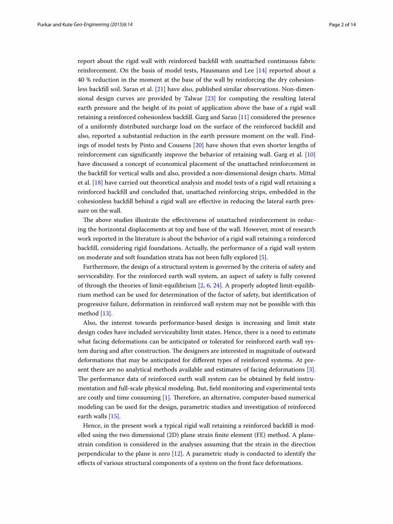
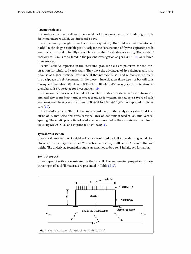
The typical cross section of a rigid wall with a reinforced backfill and underlying foundation strata is shown in Fig. 1, in which ‘b’ denotes the roadway width, and ‘H’ denotes the wall height. The underlying foundation strata are assumed to be a semi-infinite soil formation.
Soil in the backfill
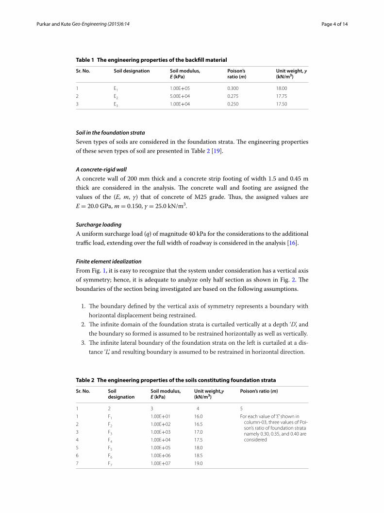
Three types of soils are considered in the backfill. The engineering properties of these three types of backfill material are presented in Table 1 [19].
Fig. 1 Typical cross-section of a rigid wall with reinforced backfill
Page 4 of 14Purkar and Kute Geo-Engineering (2015) 6:14
Soil in the foundation strata
Seven types of soils are considered in the foundation strata. The engineering properties of these seven types of soil are presented in Table 2 [19].
A concrete‑rigid wall
A concrete wall of 200 mm thick and a concrete strip footing of width 1.5 and 0.45 m thick are considered in the analysis. The concrete wall and footing are assigned the values of the (E, m, γ) that of concrete of M25 grade. Thus, the assigned values are E = 20.0 GPa, m = 0.150, γ = 25.0 kN/m3.
Surcharge loading
A uniform surcharge load (q) of magnitude 40 kPa for the considerations to the additional traffic load, extending over the full width of roadway is considered in the analysis [16].
Finite element idealization
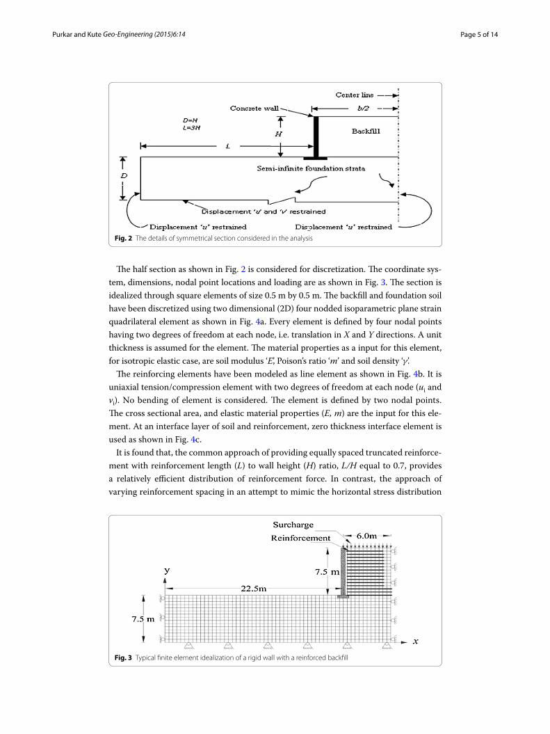
From Fig. 1, it is easy to recognize that the system under consideration has a vertical axis of symmetry; hence, it is adequate to analyze only half section as shown in Fig. 2. The boundaries of the section being investigated are based on the following assumptions.
1. The boundary defined by the vertical axis of symmetry represents a boundary with horizontal displacement being restrained.
2. The infinite domain of the foundation strata is curtailed vertically at a depth ‘D’, and the boundary so formed is assumed to be restrained horizontally as well as vertically.
3. The infinite lateral boundary of the foundation strata on the left is curtailed at a dis-tance ‘L’, and resulting boundary is assumed to be restrained in horizontal direction.
Table 1 The engineering properties of the backfill material
Sr. No. Soil designation Soil modulus, E (kPa)
Poison’s ratio (m)
Unit weight, γ(kN/m3)
1 E1 1.00E+05 0.300 18.00
2 E2 5.00E+04 0.275 17.75
3 E3 1.00E+04 0.250 17.50
Table 2 The engineering properties of the soils constituting foundation strata
Sr. No. Soil designation
Soil modulus, E (kPa)
Unit weight,γ (kN/m3)
Poison’s ratio (m)
1 2 3 4 5
1 F1 1.00E+01 16.0 For each value of ‘E’ shown in column-03, three values of Poi-son’s ratio of foundation strata namely 0.30, 0.35, and 0.40 are considered
2 F2 1.00E+02 16.5
3 F3 1.00E+03 17.0
4 F4 1.00E+04 17.5
5 F5 1.00E+05 18.0
6 F6 1.00E+06 18.5
7 F7 1.00E+07 19.0
Page 5 of 14Purkar and Kute Geo-Engineering (2015) 6:14
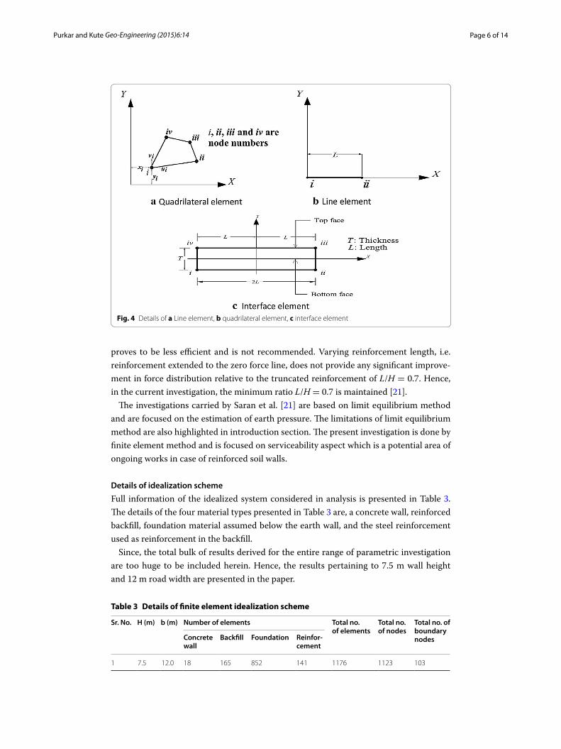
The half section as shown in Fig. 2 is considered for discretization. The coordinate sys-tem, dimensions, nodal point locations and loading are as shown in Fig. 3. The section is idealized through square elements of size 0.5 m by 0.5 m. The backfill and foundation soil have been discretized using two dimensional (2D) four nodded isoparametric plane strain quadrilateral element as shown in Fig. 4a. Every element is defined by four nodal points having two degrees of freedom at each node, i.e. translation in X and Y directions. A unit thickness is assumed for the element. The material properties as a input for this element, for isotropic elastic case, are soil modulus ‘E’, Poison’s ratio ‘m’ and soil density ‘γ’.
The reinforcing elements have been modeled as line element as shown in Fig. 4b. It is uniaxial tension/compression element with two degrees of freedom at each node (ui and vi). No bending of element is considered. The element is defined by two nodal points. The cross sectional area, and elastic material properties (E, m) are the input for this ele-ment. At an interface layer of soil and reinforcement, zero thickness interface element is used as shown in Fig. 4c.
It is found that, the common approach of providing equally spaced truncated reinforce-ment with reinforcement length (L) to wall height (H) ratio, L/H equal to 0.7, provides a relatively efficient distribution of reinforcement force. In contrast, the approach of varying reinforcement spacing in an attempt to mimic the horizontal stress distribution
Fig. 2 The details of symmetrical section considered in the analysis
Fig. 3 Typical finite element idealization of a rigid wall with a reinforced backfill
Page 6 of 14Purkar and Kute Geo-Engineering (2015) 6:14
proves to be less efficient and is not recommended. Varying reinforcement length, i.e. reinforcement extended to the zero force line, does not provide any significant improve-ment in force distribution relative to the truncated reinforcement of L/H = 0.7. Hence, in the current investigation, the minimum ratio L/H = 0.7 is maintained [21].
The investigations carried by Saran et al. [21] are based on limit equilibrium method and are focused on the estimation of earth pressure. The limitations of limit equilibrium method are also highlighted in introduction section. The present investigation is done by finite element method and is focused on serviceability aspect which is a potential area of ongoing works in case of reinforced soil walls.
Details of idealization scheme
Full information of the idealized system considered in analysis is presented in Table 3. The details of the four material types presented in Table 3 are, a concrete wall, reinforced backfill, foundation material assumed below the earth wall, and the steel reinforcement used as reinforcement in the backfill.
Since, the total bulk of results derived for the entire range of parametric investigation are too huge to be included herein. Hence, the results pertaining to 7.5 m wall height and 12 m road width are presented in the paper.
Fig. 4 Details of a Line element, b quadrilateral element, c interface element
Table 3 Details of finite element idealization scheme
Sr. No. H (m) b (m) Number of elements Total no. of elements
Total no. of nodes
Total no. of boundary nodesConcrete
wallBackfill Foundation Reinfor-
cement
1 7.5 12.0 18 165 852 141 1176 1123 103
Page 7 of 14Purkar and Kute Geo-Engineering (2015) 6:14
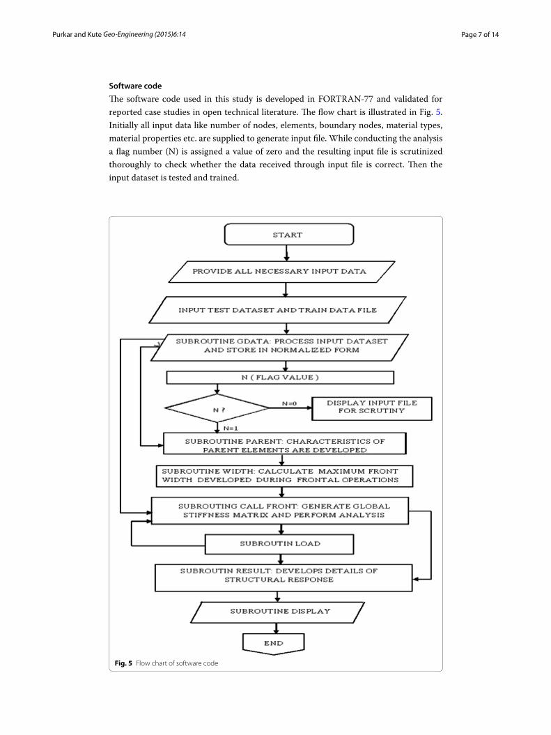
Software code
The software code used in this study is developed in FORTRAN-77 and validated for reported case studies in open technical literature. The flow chart is illustrated in Fig. 5. Initially all input data like number of nodes, elements, boundary nodes, material types, material properties etc. are supplied to generate input file. While conducting the analysis a flag number (N) is assigned a value of zero and the resulting input file is scrutinized thoroughly to check whether the data received through input file is correct. Then the input dataset is tested and trained.
Fig. 5 Flow chart of software code
Page 8 of 14Purkar and Kute Geo-Engineering (2015) 6:14
When ‘N’ is assigned a value of one, the software generates stiffness matrices for quad-rilateral element, line element and interface element considering the nodal connectiv-ity by taking the normalized input dataset. The global stiffness matrix is then obtained based on element stiffness matrices. The global stiffness matrix takes the final shape taking into account for boundary conditions. The global stiffness matrix is solved using Gauss elimination method. Using the concepts of theory of elasticity the values like stresses, strains, displacements are calculated and displayed in an organized manner.
The following subroutines are incorporated in the program.Subroutine PARENT It develops all characteristics of parent element such as shape
functions and derivates of the shape functions at various Gauss points.Subroutine GDATA The subroutine provides all Input and output data in the normal-
ized form.Subroutine WIDTH It calculates in advance the value of maximum front width that is
developed during frontal operations.Subroutine LOAD It provides the information regarding externally applied loads.Subroutine CALL FRONT It performs the analysis and establishes the nodal displace-
ments and nodal reactions.Subroutine RESULT It develops the details of the structural response, element strains,
element stresses, displacements etc.Subroutine DISPLAY It displays the results in an organized manner.
Validation of results
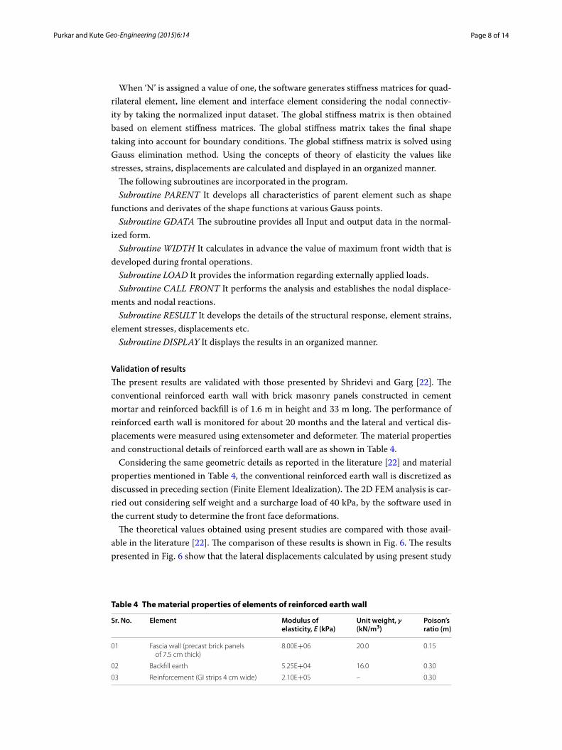
The present results are validated with those presented by Shridevi and Garg [22]. The conventional reinforced earth wall with brick masonry panels constructed in cement mortar and reinforced backfill is of 1.6 m in height and 33 m long. The performance of reinforced earth wall is monitored for about 20 months and the lateral and vertical dis-placements were measured using extensometer and deformeter. The material properties and constructional details of reinforced earth wall are as shown in Table 4.
Considering the same geometric details as reported in the literature [22] and material properties mentioned in Table 4, the conventional reinforced earth wall is discretized as discussed in preceding section (Finite Element Idealization). The 2D FEM analysis is car-ried out considering self weight and a surcharge load of 40 kPa, by the software used in the current study to determine the front face deformations.
The theoretical values obtained using present studies are compared with those avail-able in the literature [22]. The comparison of these results is shown in Fig. 6. The results presented in Fig. 6 show that the lateral displacements calculated by using present study
Table 4 The material properties of elements of reinforced earth wall
Sr. No. Element Modulus of elasticity, E (kPa)
Unit weight, γ (kN/m3)
Poison’s ratio (m)
01 Fascia wall (precast brick panels of 7.5 cm thick)
8.00E+06 20.0 0.15
02 Backfill earth 5.25E+04 16.0 0.30
03 Reinforcement (GI strips 4 cm wide) 2.10E+05 – 0.30
Page 9 of 14Purkar and Kute Geo-Engineering (2015) 6:14
near the top edge of the wall is slightly higher than the values reported by Shridevi and Garg [22]. However, at other locations these results are in good agreement.
Finite element analysis
A rigid wall retaining a reinforced backfill and underlying semi-infinite foundation strata is discretized as discussed in preceding section. The modulus of elasticity of reinforce-ment equal to 200 GPa and sectional area of 100 mm2 is kept constant for all investiga-tions. The response is derived for front face deflected profile of a rigid wall of height 7.5 m and roadway width of 12.0 m, considering self-weight of a system and are pre-sented in Fig. 7a, b. Figure 7a, b show the variation of front face deflections for a stiff-ness of 5 × 10⁴ (kPa) and Poison’s ratio of 0.275 of backfill and by varying the stiffness of foundation strata to seven types [101, 102, 103, 104, 105, 106, 107 (kPa)] and keeping Poi-son’s ratio of foundation to 0.30 as a constant value for all curves. The outward deflec-tions from the vertical line of wall are plotted as negative values and inward deflections are plotted as positive values.
The above parametric analyses show that, so long as the foundation stiffness repre-sented by the value of ‘E’ is less than that of backfill, the vertical face of the wall deflects in a manner which is shown schematically in Fig. 7a. The deflected profile as shown in
Fig. 6 The effect of height of reinforced earth wall on its lateral deflection
Fig. 7 Response of wall. a Resting on weak foundation and b resting on strong foundation

Page 10 of 14Purkar and Kute Geo-Engineering (2015) 6:14
Fig. 7a is characterized by inward deflection at the top and outward deflection at the base. Hence, it has point of rotation over the wall height. The deflected profile is a straight line variation indicating the rigid body rotation of the wall due to the defor-mations suffered by the foundation strata and backfill material. Also, the magnitude of deflections at top is more as compared to the magnitude of deflections at the base.
In case of the foundation soil having value of stiffness ‘E’ equal to or more than that of the reinforced backfill, it is observed that, the deflected profile as shown in Fig. 7b is characterized by inward deflection at the top and outward deflection at the base. Hence, it has point of rotation over the wall height. But the deflection at base is significantly small and the magnitude of deflection at the top is more as compared to the deflection at base. The deflected profile is a curved variation indicating the deformation of a rigid wall due to increased shear stress at the base of wall.
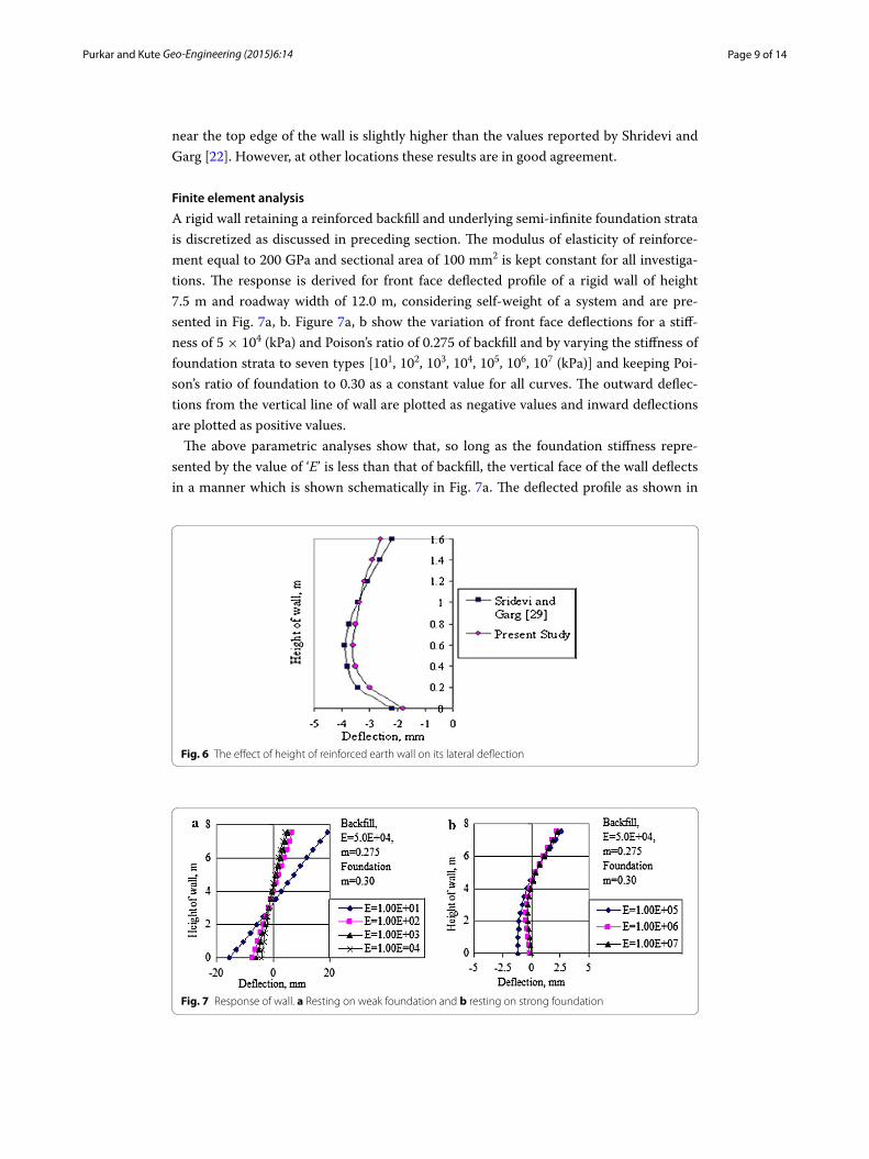
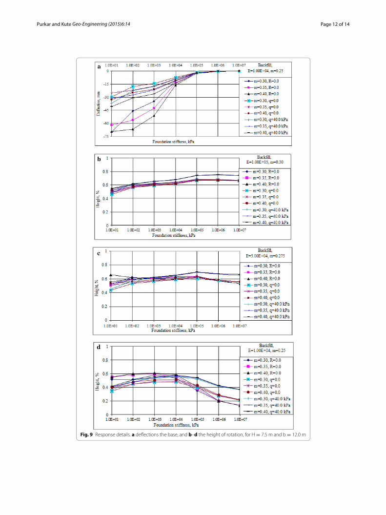
Discussion on resultsThe response is derived for wall height 7.5 m and road width 12.0 m considering self-weight of wall in the preceding section. Similar response is obtained for other parametric combinations by varying the properties of backfill and foundation strata (vide Tables 1, 2). The response is derived for three cases; i.e. backfill with no reinforcement (R = 0.0), back-fill with self weight (q = 0.0) and backfill with a uniform surcharge load (q) of 40.0 kPa and are presented in Figs. 8a–e, 9a–d. The Figs. 8a–e, 9a–d show the front face deflections at top and base and the height of rotation from base in percentage height for the entire range of three types of embankment and seven types of foundations. In each figure, the stiffness and Poison’s ratio of embankment is kept constant. Front face deflections are plotted by varying the stiffness of foundation to seven types. First three curves show the response of a system with self-weight without reinforcement. The next three curves show the response of a system by considering the self-weight with a reinforced backfill, and last three curves show the response of a system with a reinforced backfill, considering a constant surcharge load of 40 kPa extended over full width of the wall. For each value of foundation stiffness three values of Poison’s ratio (0.30, 0.35, and 0.40) are considered as shown in legend.
From the literature review, it is revealed that, at present there are no analytical methods available to estimate the facing deformations [3]. Also, the estimation of facing deforma-tions have been restricted to a design charts proposed by Chrsitoper et al. (FHWA [9]).The case of a rigid wall retaining reinforced cohesive-frictional backfill subjected to uni-formly distributed surcharge load has been analyzed by Mittal et al. [18] using limit equi-librium approach. They have concluded that, there is about 40 % reduction in the lateral earth pressure on the wall due to reinforced backfill. In the current investigation backfill is assumed cohesionless and the wall is resting on variety of soil types from soft clay to hard strata. The observations noted from the study are discussed below.
The Figs. 8a–e, 9a shows the front face deflections at top and base of wall. The observa-tions noted from these figures show that, for foundation strata having stiffness 101 kPa is distorted due to low shear strength and even reinforced backfill is not effective to reduce the front face deflections.
The reinforced backfill having stiffness 104 kPa, constructed on foundation strata hav-ing stiffness 102–104 kPa, the front face deflections at top and base are reduced up to 60 %.
Page 11 of 14Purkar and Kute Geo-Engineering (2015) 6:14
Fig. 8 Response details. a–c Front face deflections at the top, d, e deflections the base, for H = 7.5 m and b = 12.0 m
Page 12 of 14Purkar and Kute Geo-Engineering (2015) 6:14
Fig. 9 Response details. a deflections the base, and b–d the height of rotation, for H = 7.5 m and b = 12.0 m
Page 13 of 14Purkar and Kute Geo-Engineering (2015) 6:14
Also, the reinforced backfill having stiffness 5 × 10⁴ kPa, constructed on foundation strata having stiffness 102–104 kPa, the front face deflections at top and base are reduced up to 40 %.
The reinforced backfill having stiffness 105 kPa, constructed on foundation strata hav-ing stiffness 102–104 kPa, the front face deflections at top and base are reduced up to 30 %.
The Fig. 9b–d show the effect of foundation stiffness on height of rotation of wall. The observations noted from these figures indicate that, the height of rotation increases as the foundation stiffness increases from101 to104 kPa. Also, the height of rotation decreases as the foundation stiffness increases from 105 to107 kPa.
When, the wall resting on strong foundation (stiffness, 105, 106, 107 kPa) the reduction in front face deflections at top due to reinforced backfill is hardly 20 % and at base the deflections tend to zero.
Hence, it is concluded that, the reduction in front face deformation varies from 20 to 60 % depending on backfill and foundation soil properties. The results obtained by Mittal et al. [18] are specific to reduction in lateral earth pressure on the wall. There is no direct evidence in the published literature to prove the validity of results. But, the trend of reduction in front face deformations (20–60 %), depends upon the properties of backfill and foundation strata and is same as reported by Mittal et al. [18]. Hence, the current approach is an attempt of the writers to use the proposed methodology as a first order estimate of lateral displacements during construction of rigid walls. Additionally, the paper highlights potential areas of ongoing and further work that may offer a better understanding of the serviceability limit state of reinforced soil walls.
Summary and conclusionsBased on the study of a rigid wall retaining a reinforced backfill, the following major conclusions have been drawn, which are summarized below.
1. As long as the stiffness of foundation represented by the value of ‘E’ is less than that of the stiffness of reinforced backfill, the rotation of a rigid concrete wall is observed at a particular height, imparting inward deflection at the top of wall and outward deflection at the base of wall. The deflected profile is a straight line variation indicat-ing the rigid body rotation of the wall due to the deformations suffered by the foun-dation strata and backfill material.
2. In case of the foundation soil having value of stiffness ‘E’ equal to or more than that of the reinforced backfill, the deflected profile is curved variation indicating the deformation of a rigid wall due to increased shear stress at the base of wall.
3. Unattached reinforcing strips, embedded in the backfill behind a rigid retaining wall, are effective in reducing the horizontal front face deflections at top and base of a rigid wall.
4. In case of weaker foundation, the response of the wall is sensitive to Poison’s ratio. The front face deflections change as the Poison’s ratio changes. But for strong foun-dation, the response is insensitive to Poison’s ratio.
5. The present work demonstrates the methodology to derive the design charts for deflections at top and base and height of rotation of a rigid wall. These charts are useful to the designer to choose the option of a rigid wall with a reinforced backfill,
Page 14 of 14Purkar and Kute Geo-Engineering (2015) 6:14
considering the available foundation and to satisfy the codal provisions regarding the serviceability criteria of a rigid wall. Additionally, the paper highlights potential areas of ongoing and further work that may offer a better understanding of the serviceabil-ity limit state of reinforced soil walls.
Author’s ContributionMSP carried out the numerical analysis and drafted the manuscript. SK reviewed the manuscript. Both authors read and approved the final draft of manuscript.
Competing interestsThe authors declare that they have no competing interests.
Received: 14 September 2014 Accepted: 26 October 2015
References 1. Abdelouhab A, Dias D, Freitag N (2011) Numerical analysis of the behavior of mechanically stabilized earth walls
reinforced with different types of strips. Geotext Geomembr 29(2):116–129 2. Baker R, Klein Y (2004) An integrated limiting equilibrium approach for design of reinforced soil retaining structures:
part I—formulation. Geotext Geomembr 22(3):151–177 3. Bathurst RJ, Miyata Y, and Allen TM (2010) Facing Displacements in Geosynthetic Reinforced Walls. Invited keynote
paper, Earth Rentention Conference 3 (ER2010), ASCE, Geo-Institute, Bellevue, Washington, 1–4 August, pp 442–457 4. Bayoumi A, Bobet A, Lee J (2008) Pullout capacity of a reinforced soil in drained and undrained conditions. Finite
Elem Anal Des 44:525–536 5. Bergado DT, Youwai S, Teerawattanasuk C, Visudmedanukul P (2003) The interaction mechanism and behaviour of
hexagonal wire mesh reinforced embankment with silty sand backfill on soft clay. Comput Geotech 30:517–534 6. Blatz JA, Bathurst RJ (2003) Limit equilibrium analysis of large-scale reinforced and unreinforced embankments
loaded by strip footing. Can Geotech J 40:1084–1092 7. Boyle SR (1995) Deformation prediction of geosynthetic reinforced soil retaining walls. Ph.D. Dissertation, University
of Washington, USA 8. Broms BB (1987) Fabrics reinforced soils. In: Proceedings International Symposium on Geosynthetics-Geotextiles
and Geomembranes. Koyoto, Japan, pp 13–54 9. Christoper BR, Gill SA, Giroud JP, Mitchell JK, Schlosser F, Dunnicliff J (1989) Reinforced soil structures: Vol I, Design
and Construction Guidelines; Vol II, Summary of Research and Systems Information. FHWA RD 89-043, Federal High-way Administration, Washington, DC
10. Garg KG, Ramesh C, Chandra S, Ahmad Z (2002) Performance of instrumented wall retaining reinforced earth fill. Indian Geotech J 32(4):364–381
11. Garg KG, Saran S (1997) Effective placement of reinforcement to reduce lateral earth pressure. Indian Geotech J 27(4):353–376
12. Golam K, Hossain S, Khan MS (2014) Influence of soil reinforcement on horizontal displacement of MSE wall. Int J Geomech ASCE 14(1):130–141
13. Han J, Leshchinsky D (2004) Limit equilibrium and continuum mechanics-based numerical methods for analyzing stability of MSE walls. In: Proc., 17th ASCE Engineering Mechanics conf., ASCE, Reston, VA
14. Hausmann MR, Lee KL (1978) Rigid model wall with soil reinforcement. In: Proc. Sym. On soil reinforcing and stabiliz-ing techniques, Sydney, Australia, pp 175–190
15. Hossain MS, Kibria G, Khan MS, Hossain J, Taufiq T (2012) Effects of backfill soil on excessive movement of MSE wall. J Perform Constr Facil 26(6):793–802. doi:10.1061/(ASCE)CF.1943-5509.0000281
16. IRC: 6 (1966) Standard specifications and code of practice for roads and bridges, section II, loads and Stresses; Reprint, pp 1–37 (1994)
17. Kazimierowicz-Frankowska K (2005) A case study of geosynthetic reinforced wall with wrap-around facing. Geotext Geomembr 23(1):107–116
18. Mittal S, Garg KG, Saran S (2006) Analysis and design of retaining wall having reinforced cohesive frictional backfill. Geotech Geol Eng 24(3):499–522
19. Nayak NV (1996) Foundation design manual, 5th edn. Dhanpat Rai Publications, New Delhi 20. Pinto NIM, Cousens TW (1996) Geotextile reinforced brick faced retaining walls. Geotext Geomembr 14:449–464 21. Saran S, Garg KG, Bhandari RK (1992) Retaining wall with reinforced cohesionless backfill. J Geotech Eng ASCE
118(12):1869–1888 22. Sridevi J, Garg KG (1997) Finite element analysis of a reinforced earth wall. Indian Geotech J 27(1):59–73 23. Talwar DV (1981) Behaviour of reinforced earth retaining structures and shallow foundations. Ph.D. Thesis, Dept. of
Civil Eng, Univ. of Roorkee, Roorkee, India 24. Varadarajan A, Sharma KG, Aly MAA (2000) Design of reinforced embankment by limit equilibrium and finite ele-
ment method. Indian Geotech J 30(3):100–132 25. Yoo C, Kim SB (2008) Performance of a two-tier geosynthetic reinforced segmental retaining wall under a surcharge
load: full-scale load test and 3D finite element analysis. Geotext Geomembr 26(6):460–472 26. Zhang MX, Zhou H, Javadi AA, Wang ZW (2008) Experimental and theoretical investigation of strength of soil rein-
forced with multi-layer horizontal-vertical orthogonal elements. Geotext Geomembr 26(1):1–13