Embed Size (px)
Citation preview
Eng. & Tech. Journal ,Vol.29, No.11, 2011
* College of Engineering,University of Basrah /Basrah 2102
Finite Element Analysis of Deformation Behavior of Wire Cold Flat Rolling
Dr. Abdul Kareem Flaih Hassan*
Received on: 24 /10/ 2010 Accepted on: 5/5/ 2011
Abstract
Flat rolling of wire is an industrial process used to manufacture electrical flat wire, medical catheters, springs and piston segments, among other products. This paper presents a 3D finite element analysis of wire flat rolling. The variations of rolling force due to roll speed changes, Effect of reduction in height on width of contact Area, and Lateral spread of wire has been discussed. It is found that a negligible increase in flow stress and rolling force does occur due to increase in the strain rate at room temperature. Besides, the results showed that the behavior of rolling force variation versus roll speed depends on the rolling reductions. A theoretical relationship has been developed to relate the reduction in height of wire to the width of contact area between the rolls and wire. This relationship depicts that the width of contact area is proportional to square root of reduction in height of wire. Finally the finite element can give a reasonable estimation of the deformation behavior in wire flat rolling, since the theoretical predictions are reasonable agreement with the experimental measurements of other authors. Keywords: wire flat rolling, wire cold rolling
طريقة العناصر المحددة لعملية درفلة ا�س�ك باستخدامتحليل سلوك التشوه
الخ�صة
ات الكھربائي��ة والطبي��ة وف��ي ف��ي الص��ناع تس��تعمل ص��ناعيةُ عملي��ةُ ل�س���ك مس��تويةدرفل��ة الالتعتب��ر لمح�ددة باس�تخدام طريق�ة العناص�ر ا ث�ث�ي ا1بع�اد تحلي�ل ق�دمي ا العم�لھ�ذ. واج�زاء المك�بس الن�وابظصناعة
ت�اثير النقص�ان ، سرعة الدرفلة عل�ى ق�وة الدرفل�ة التغير في تم دراسة تاثير .كفلة المستوية ل�س�لعملية الدراوض�حت النت�ائج وج�ود زي�ادة طفيف�ة ف�ي .، والتشوه الجانبي للسلكفي ا1رتفاع على عرض مساحة الت�مس
ف��ي ال�ى الزي�ادة الملحوظ��ة ف�ي مع�دل ا1نفع�ال اجھ�اد ا1نس�ياب وان الس�بب ف��ي زي�ادة ق�وة الدرفل�ة يع��ود ال�ىمق��دار عل��ى يَعتم�دُ مختلف��ة درفل�ة س��رع عن�د الدرفل��ة ق��وةِ ل�وحظ ان ذل��ك، إل�ى إض��افةً . درج�ة ح��رارة الغرف�ة
تفسر الع�قة ب�ين مق�دار التخف�يض ف�ي قط�ر الس�لك تم استنباط ع�قة رياضية نظرية .في ا1رتفاعالتخفيض ع��رض مس��احة ال��ت�مس ھ��ذه الع�ق��ة وج��د ان لم��ن خ���. ال��درفيلولس��لك وع��رض مس��احة ال��ت�مس ب��ين ا
بينت النتائج المستنبطة من نظري�ة العناص�ر . للتخفيض في ارتفاع السلكمع الجذر التربيعي "طرديا يتناسبالمح��ددة ان ھنال��ك تواف��ق مقب��ول ف��ي تخم��ين س��لوك التش��وة لعملي��ة درفل��ة ا1س���ك مقارن��ة م��ع نت��ائج عملي��ة
.ن اخرينلباحثي على البارد �س�ك ، درفلة ا1س�كل المستوية درفلة: ةكلمات مرشد
Eng. & Tech. Journal, Vol.29, No.11, 2011 Finite Element Analysis of Deformation Behavior of Wire Cold Flat Rolling
2103
1. Introduction
he rolling process is one of the most popular processes in manufacturing industries in that
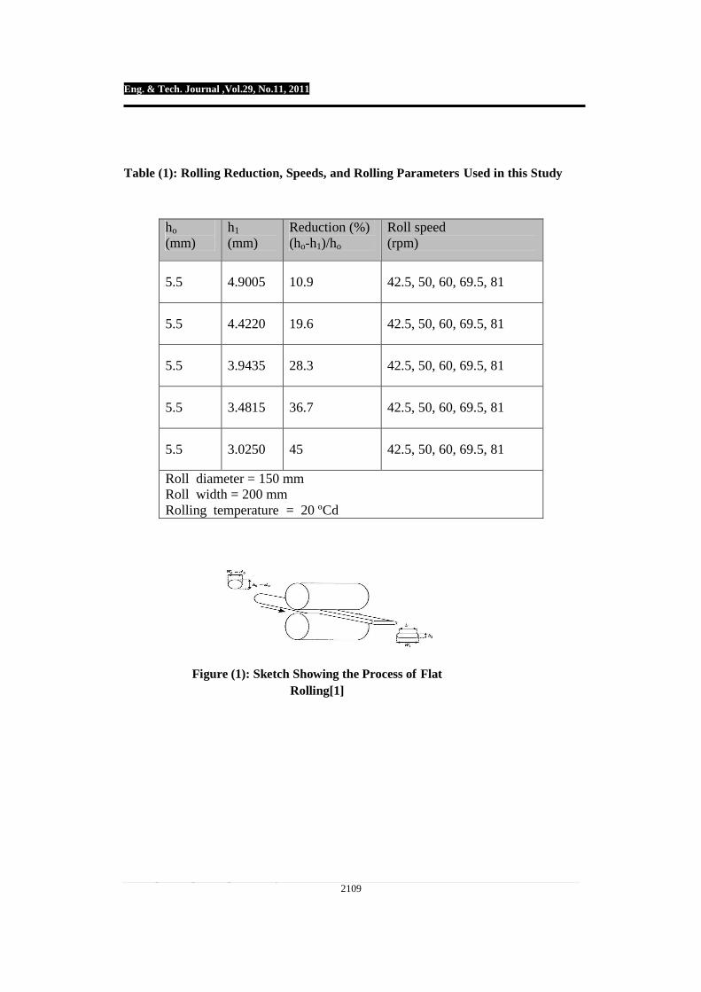
almost 80% of metallic equipment has been exposed to rolling, at least one time in their production period. Among all kinds of the rolling processes, the flat rolling is the most practical one. In industrial countries, about 40–60% of rolling products are produced with this type of rolling. Therefore, many scientists have tried to enhance the quality and quantity of products by optimizing this process and identifying parameters affecting it to satisfy their customers. Flattened wires are widely used in saw blades, spring, piston rings and transformer industries. These wires are produced by the process of flat rolling, see Fig.(1). In this process, wire of circular cross section is cold rolled between two flat rolls in one or several passes to achieve the desired thickness to width ratio [1]. Finite element models have been used to analyze a number of metal-forming processes [2]. However, few models have been developed to simulate flat roll-forming processes. These processes present many computational challenges to finite element analysis. One difficulty is that full-length die contours must be modeled since the stressed area of the die changes as the forming operation progresses. Another difficulty is that nodal coordinates must be updated constantly because the blanks rotate and translate at the same time. Additionally, friction and slippage between the dies and the workpiece must be considered.
Finally, very high mesh densities are required because of the massive three-dimensional material flow in the blanks.
These flat rolling characteristics increase the number of calculations at each step of the simulation.
An empirical formula for determining spread in flat rolling process was proposed and applied by Wusatowki[3], Based on Wusatowski’s work, Mauk[4] has proposed the iteration method, and Bursal et al.[5] have used the vertical slab method for analysis. More general empirical formulas for various rolling shapes were proposed by Saito et al.[6,7] and Shinokura and Takai[8,9] by combining the experimental results shape rolling and spread formula for flat rolling.
The flat rolling of wire combines the problems of lateral spread and anisotropy. The old empirical methods used to hot rolling of shapes cannot be used to predict the spread. The single option is to use 3D finite elements with an anisotropic material formulation. As a means of controlling the accuracy of the program, experimental flat rolling can be carried out and the results compared to the FE predictions[10]. 2. Theoretical Background 2.1 Width of Contact Area Between the Rolls and Wire To achieve a relation between the width of contact area, i.e. b value in Fig.1, and the reduction in height of wire, the deformation pattern during flat rolling of wire is considered. The reduction in height of wire, ∆h, defined as
11 hhhdh oo −=−=∆ … (1)
T
Eng. & Tech. Journal, Vol.29, No.11, 2011 Finite Element Analysis of Deformation Behavior of Wire Cold Flat Rolling
2104
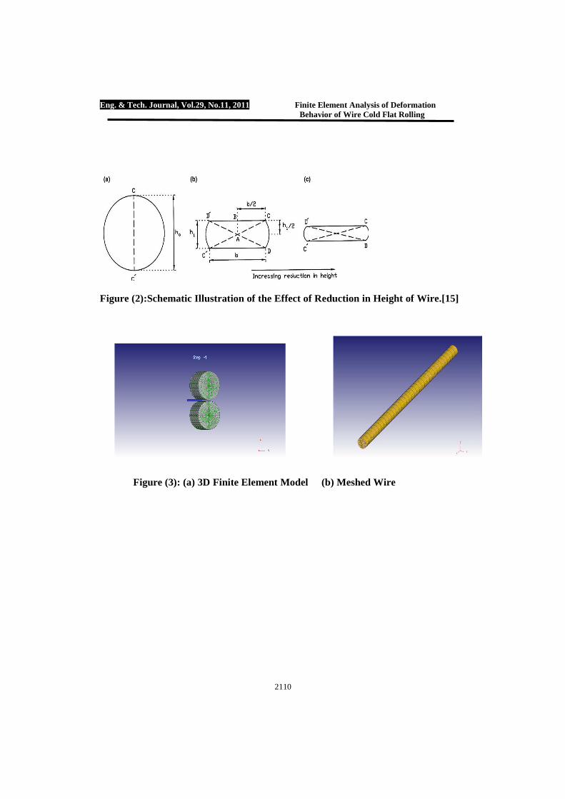
where d0(=h0), and h1 are the initial diameter of wire and the final height of the flattened wire, respectively. In side pressing test of rod, macroscopic shear bands are produced by the formation of two dead metal zones due to the existence of friction between the tools and wire [11]. It has been reported that the shear bands are observed in metallographic cross-section of rods and their morphology follows the reduction in height of rods, as shown in Fig.(2) b and c. The shear bands are in an X form as shown in the figure. These bands may be considered as the slip line in side pressing test [12]. It has been ascertained that with increasing the reduction in height, the legs of the X rotate away from the primary compression axis[11,13]. From the FEM results presented by Iankov[14] and Pesin et al. [15] for the wire flat rolling process, one may conclude that after flat rolling the wire, there are two bands of X form in cross-section of wire with extremely difference in deformation with respect to the other area. Using the idea of rotation of X legs with increasing the reduction in height of wire, the width of contact area between the wire and rolls in wire flat rolling process can be calculated. Regarding to this point, the b value can be calculated by the following relation in region ABC of Fig.(2 )b[16,17]:
444
221
2ohhb =+ ... (2)
)( 121
2 hhhhhb oo +∆=−= . (3)
)2( hhhb o ∆−∆= … (4)
Actually, the length of bands is
slightly increased. If it is assumed that the increase is equal to ∆h/2,
Eq. (4) can be written as:
hhb o∆= 2 … (5)
2.2 Lateral Spread of Wire in Wire Flat Rolling
Another important parameter in wire flat rolling process is the lateral spread of the wire. An approach reported for the spread in strip rolling is as follows [18]: The mean vertical stress between the rolls and strip can be regarded as the normal pressure (s), corresponding to a lateral compressive stress of ms, where m is a function of the geometry of the plastic zone, rolling temperature and composition [6]. The value of m lies between that of plane strain and plane stress deformation condition, i.e.
2/10 ≤≤ m . Neglecting the stress in the longitudinal direction, then from the Levy–Mises plastic stress–strain relations, we get [18]
2
10
2
21
3
2 ≤≤=−
−=−
ppm
m
d
d
εε … (6)
p
o
oo
o
h
h
W
Wrp
h
h
W
W
==
1
1
1
1
0
ln
ln
… (7)
where and are the strains
in width and height and W0, W1, h0 and h1 are the initial width, final width, initial height and final height of strip, respectively.
Using the experimental results, Wusatowski has suggested the
Eng. & Tech. Journal, Vol.29, No.11, 2011 Finite Element Analysis of Deformation Behavior of Wire Cold Flat Rolling
2105
following relationship for the spread in strip rolling process [18,19]:
po
h
hdcba
W
W)(
12
1 ′′′′= … (8)
where p is a function of the roll diameter and ratio of initial width to height of strip. Also,
dandcba ′′′′ ,,, are correction
factors, slightly different from unity, which allow for the variation in steel composition, rolling temperature, rolling speed and roll material, respectively [18]. It is interesting to note that Eq.(7) is similar to Eq.(8) derived from the experimental results. The difference between these relationships is due to the existence of stress in the longitudinal direction. To develop spread formula for flat rolling of wire one may modify Eq.(8) by assuming that W0 = h0 = d0, where d0 is the initial diameter of wire. At each deformation condition, h1, b, and W1, shown in Fig.(1), were calculated. Thus, using the calculated values, the graphs of W1/W0 versus h0/h1 were plotted at different roll speeds. 3. Finite Element Modeling
In this research the code DEFORM-3D V6.1 was used to perform finite element analysis of wire flat-rolling process. This software is specifically designed to analyze bulk plastic deformation, and is especially suited for the present analysis. It takes advantage of the fact that plastic deformation is usually highly localized. It assigns rigid elements to the regions of the part that are not deforming, thereby reducing the number of calculations performed at each step of the simulation [20]. It also updates nodal coordinates using a
higher order scheme. This special algorithm accurately takes into account the rotation of the object when calculating new location of the rolled part. Details of this code are well established and have been reported elsewhere [21–24].
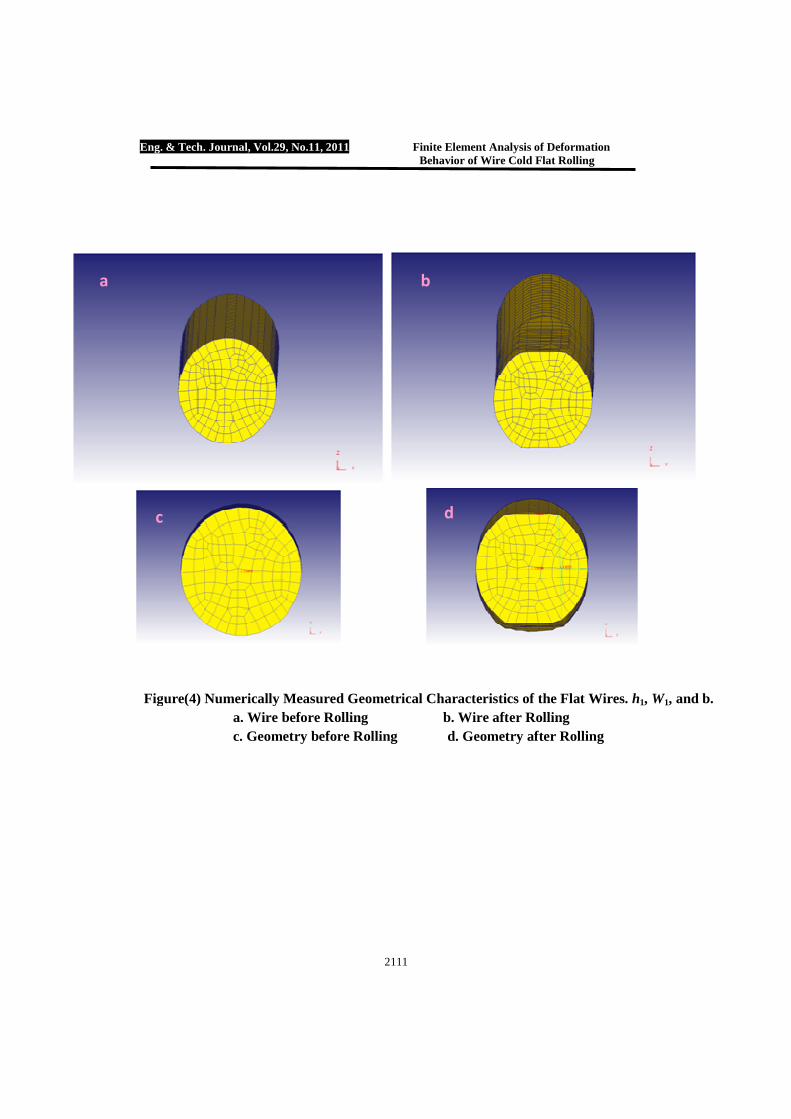
A 3D finite element rolling model has been constructed to simulate a single pass of the wire flat rolling process, see Fig.(3).High carbon steel wires of 5.5 mm diameter were used as the simulated material in this work. The rolling parameters are shown in Table (1). At each deformation condition the rolling force and geometrical characteristics of the flat wires i.e. h1, W1, and b were numerically estimated by the finite element code, see
Figure(4). The rolling reduction in height was defined as
11,2 handrwherehr oo − are the
radius of initial wire and the final height of flat wire, respectively. 4. Results and Discussion
To validate the predicted results obtained from the constructed finite element model, it is necessary to compare these results with experimentally measured data. The experimental data of Kazeminzhad and Taheri [1] were chosen to achieve this validation. The validation of the predicted results can be arranged in the following manner. 4.1 Variations of Rolling Force Due to Roll Speed Changes
Fig.(5) shows the effect of rolling speed on the rolling force at different percentage reduction in height. It is clear that increasing the rolling reduction, increases the rolling force. This can be attributed to the increase in redundant work due to large plastic
Eng. & Tech. Journal, Vol.29, No.11, 2011 Finite Element Analysis of Deformation Behavior of Wire Cold Flat Rolling
2106
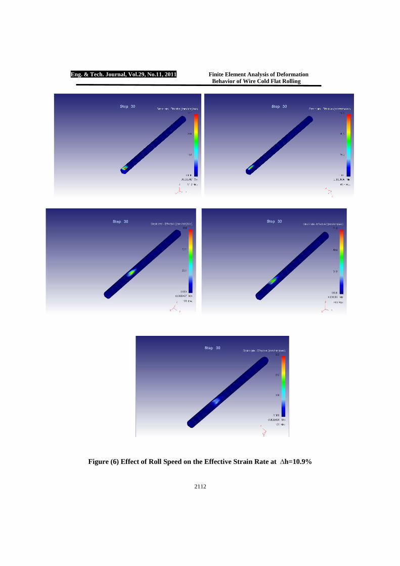
deformation accompanied with high reduction. Moreover in some ranges of rolling speed, the rolling force decrease while in the other ranges it increases. Rowe [25] reported that by increasing the roll speed, the redundant work increases near the surface of the workpiece. Regarding this point, increasing the roll speed can increases the rolling force. Zhang and Lenard [26] noticed that by increasing the roll force, the coefficient of friction between the wire and rolls decreases resulting in reduction of friction work, it is, therefore, concluded that by increasing the roll speed, the rolling force are decreases. Fig.(6) shows the effect of roll speed on the strain rate at constant percentage reduction in height ∆h=10.9% at room temperature. It can be seen that increasing the roll speed will increases the strain rate, while roll speed has a negligible effect on the flow stress as the strain rate sensitivity exponent for high carbon steel at room temperature is very small. 4.2 Effect of Reduction in Height on Width of Contact Area
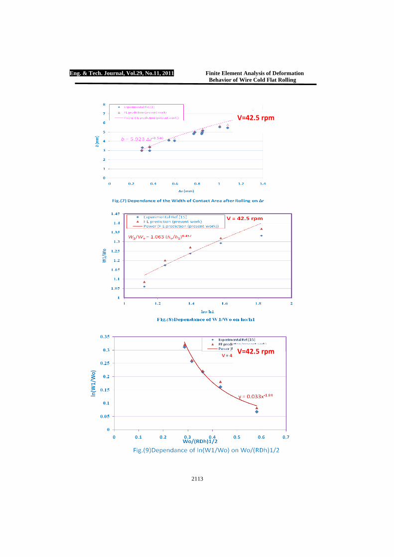
The variations of final width of contact area, b, versus the reduction in height at roll speed V=42.5 rpm are
shown in Fig.(7). represents the
value of deformation which happens in the radius of wire during rolling and can be calculated using the relation.
( ) 2/2 1hrr o −=∆ . Kazeminzhad
and Taheri[1] proposed an empirical
relationship between b and
denoted by. rb ∆= 64.5 . The relationship between b and, r∆ derived from the results of finite element prediction, show that there is a
good agreement with empirical relationship. Also it is observed that the b value is proportional to the square root of reduction in height of wire. This result is consistent with the results presented by Pater and Weronski [12,17] for the width of contact area in cross-wedge rolling and rotational compression of rod. 4.3 Lateral Spread of Wire The graph relating
11 // hhtoWW oo at a roll speed of
42.5 rpm was shown in Fig.(8). As can be seen from the figure, increasing
1/ hho , the magnitude of oWW /1 is
increased and the following relationship can be derived 5. Conclusions
1. The finite element method can give a good agreement for the prediction of deformation behavior in wire flat rolling using
2. A negligible increase in flow stress and rolling force does occur due to increase in the strain rate at room temperature.
3. The behavior of rolling force variation versus roll speed depends on the rolling reductions.
4. During the deformation of flat wire rolling, the b value is proportional to the square root of reduction in height of wire.
6. References [1] M. Kazeminezhad, A. Karimi
Taheri, “An experimental investigation on the deformation behavior during wire flat rolling process”, Journal of Materials Processing Technology, 160, 2005, 313-320.
Eng. & Tech. Journal, Vol.29, No.11, 2011 Finite Element Analysis of Deformation Behavior of Wire Cold Flat Rolling
2107
[2] J. Chakrabarty, “ Applied Plasticity”, Springer, New York,
2000, p. 651.
[3] Z. Wusatowski, “ Fundamentals of Rolling”, Pergamon Press, New York, 1969
[4] P.J. Mauk, “ Computer-aided roll pass design”, Doctoral Dissertation, Technical University of Aachen, Aachen, Germany, 1983.
[5] F. Bursal, K. Sevenler, P. S. raghupathi, “ Computer-aided analysis of metal flow in the rolling of rods and structural profiles”. Int. J. Mach. Tool. Manu., 28 , 1988, pp 475-482.
[6] Y. Saito, Y. Takahashi, K. Kato, “ Calculation of spread, elongation, effective roll radius, roll force and torque when rolling in the square-diamond, square-oval, and round-oval passes”, J. Iron Steel Inst., Japan, 2, 1983, 1070-1077.
[7] Y. Saito, Y. Takahashi, M. Moriga, K. Kato “ A new method for calculating deformation and force parameters in steel rod rolling and its application to roll pass design”, J. Jpn. Soc. Technol. Plas. 24, 1983, 1070-1077.
[8] T. Shinokura, K. Takai,” A new method for calculating spread in rod rolling”, J. Applied metal working, 2, 1982, 147-160.
[9] T. Shinokura, K. Takai,” Mathematical models of roll force and torque in steel bar rolling”, J. Iron Steel Inst., 14, 1986, 58-64.
[10] Bjorn Carlsson, “ The contact pressure distribution in flat rolling of wire”, Journal of Materials Processing Technology, 73, 1998, 1-6.
[11] Semiatin SL. Jonas JJ., “Formability and workability of metals: Plastic instability and flow localization”, USA, ASTM 1984.
[12] Pater Zb, Weronski W.,” Determination of the contact area between the rolling tools and the workpiece in cross rolling process”, J. Mater Process Technol., 1994;45:105–110.
[13] Shahan A. R., Karimi Taheri A., ” Adiabatic shear bands in titanium and titanium alloys”, Materials and Design, 1993; 14(4), 243-250.
[14] Iankov R., “ Finite element simulation of profile rolling of wire”, J. Mater. Process. Technol., 2003; 142; 355-361.
[15] Pesin A., Salganik V., Trahtengertz E., Chemiahovsky M., Rudakov V., “Mathematical modeling of the stress-strain state in asymmetric flattening of metal band” , J. Mater Process. Technol., 2002; 125-126;689-694.
[16] M. Kazeminezhad, A. Karimi Taheri, “A theoretical and experimental investigation on wire flat rolling process using deformation pattern”, Journal of Materials and Design 26 (2005) 99–103.
[17] Pater Zb. “Analysis of plane-strain rotational compression of rod by FEM”, J., Mater Process Technol., 1996;60:549–554.
[18] Chitkara NR, Johnson W., “Some experimental results concerning spread in the rolling of lead”, ASME J. Basic Eng 1966(June):489–499.
[19] Helmi A., Alexander J.M,.”Geometric factors affecting spread in hot flat rolling of steel”, J. Iron Steel Inst. 1968:1110–1117.
[20] J.T. Jinn, “ DEFORM Users Group Meeting Presentation, Scientific Forming Technologies Corporation”, Columbus, OH, May 2002.
Eng. & Tech. Journal, Vol.29, No.11, 2011 Finite Element Analysis of Deformation Behavior of Wire Cold Flat Rolling
2108
[21] S.I. Oh, W. Wu, J. Tang, A. Vedhanayagam,” Capabilities and applications of the FEM code Deform: the perspective of the developer”, Journal of Materials Processing Technology, 1991, 25–42.
[22] W.T. Wu, G. Li, A. Arvind, J.P. Tang, “ Development of a three dimensional finite element method based process simulation tool for the metal forming industry”, Proceedings of the 1996 European Conference on Engineering Systems Design and Analysis, vol.3, PD-vol. 75, American Society of Mechanical Engineers, New York, 1996, pp. 143–150.
[23] W. T. Wu, S. I. Oh, “ ALPIDT: a general purpose FEM code for simulation of non-isothermal forming processes”, Transactions of the North American SME XIII Manufacturing Research Conference, vol. 13, May 1985, pp. 449–455.
[24] W.T. Wu, S.I. Oh, T. Altan, R.A. Miller, “ Automated mesh generation for forming simulation”, Computers in Engineering 1990, Proceedings of the 1990 ASME International Computers in Engineering Conference, American Society of Mechanical Engineers, New York, 1990, pp. 507–515.
[25] G.W. Rowe, “An Introduction to the Principles of Metalworking”, Edward Arnold, 1965.
[26] S. Zhang, J.G. Lenard, “ The effect of the reduction, speed and lubrication viscosity on friction cold rolling”, J. Mater. Process. Technol., 30, 1992, 197-210.
Eng. & Tech. Journal ,Vol.29, No.11, 2011
* College of Engineering,University of Basrah /Basrah 2109
Table (1): Rolling Reduction, Speeds, and Rolling Parameters Used in this Study
ho (mm)
h1 (mm)
Reduction (%) (ho-h1)/ho
Roll speed (rpm)
5.5 4.9005 10.9 42.5, 50, 60, 69.5, 81
5.5 4.4220 19.6 42.5, 50, 60, 69.5, 81
5.5 3.9435 28.3 42.5, 50, 60, 69.5, 81
5.5 3.4815 36.7 42.5, 50, 60, 69.5, 81
5.5 3.0250 45 42.5, 50, 60, 69.5, 81
Roll diameter = 150 mm Roll width = 200 mm Rolling temperature = 20 ºCd
Figure (1): Sketch Showing the Process of Flat Rolling[1]
Eng. & Tech. Journal, Vol.29, No.11, 2011 Finite Element Analysis of Deformation Behavior of Wire Cold Flat Rolling
2110
Figure (2):Schematic Illustration of the Effect of Reduction in Height of Wire.[15]
Figure (3): (a) 3D Finite Element Model (b) Meshed Wire
Eng. & Tech. Journal, Vol.29, No.11, 2011 Finite Element Analysis of Deformation Behavior of Wire Cold Flat Rolling
2111
Figure(4) Numerically Measured Geometrical Characteristics of the Flat Wires. h1, W1, and b. a. Wire before Rolling b. Wire after Rolling c. Geometry before Rolling d. Geometry after Rolling
a b
c d
Eng. & Tech. Journal, Vol.29, No.11, 2011 Finite Element Analysis of Deformation Behavior of Wire Cold Flat Rolling
2112
Figure (6) Effect of Roll Speed on the Effective Strain Rate at ∆h=10.9%
Eng. & Tech. Journal, Vol.29, No.11, 2011 Finite Element Analysis of Deformation Behavior of Wire Cold Flat Rolling
2113
V=42.5 rpm
V=42.5 rpm