Embed Size (px)
Citation preview

Finite-element analysis of stress in the canine diaphragm
S. S. MARGULIES, G. T. LEI, G. A. FARKAS, AND J. R. RODARTE University of Pennsylvania, Philadelphia, Pennsylvania 19104; Mayo Clinic and Foundation, Rochester, Minnesota 55905; and Baylor College of Medicine, Houston, Texas 77030
Margulies, S. S., G. T. Lei, G. A. Farkas, and J. R. Rodarte. Finite-element analysis of stress in the canine dia- phragm. J. Appl. physiol. 76(5): 2070-2075, 1994.-Stress in the diaphragm, transdiaphragmatic pressure, and diaphragm shape are interrelated by a balance of forces. Using precise in vivo measurements of diaphragm shape and transdiaphragma- tic pressure distribution in combination with finite-element analysis (ANSYS), we determined the direction and magnitude of stress in the passive diaphragm at relaxation volume. Lead spheres sutured along muscle bundles identified muscle bundle location and orientation in vivo. The x, y, and z coordinates of the lead spheres and entire surface of the diaphragm, excluding the zone of apposition, were determined to within 1.4 mm. Thin shell elements were used to construct a finite-element model of the diaphragm with a 2.1- to 4.2-mm internodal spacing. The diaphragm was assumed to have a uniform thickness of 2.5 mm, and magnitude and direction of the principal stresses were computed. The results show that 1) diaphragm stress is nonuni- form and anisotropic (i.e., varies both with location on dia- phragm surface and direction examined), 2) largest stress ( ol) is aligned with muscle bundles and is two to four times larger than g2 (perpendicular to CT~ in diaphragm plane), and 3) stress along the muscle bundle is larger in vivo under conditions of biaxial stress than at same length in vitro under uniaxial stress. Although diaphragm stress and tension have often been as- sumed to be uniform, our finding that stress is oriented primar- ily along the muscle fibers should be considered in future mod- els of the diaphragm. Moreover, the inequality between in vivo stress and stress in an isolated muscle bundle indicates that caution is required when extrapolating in vitro muscle data to the in vivo environment.
pulmonary mechanics; respiratory muscle; passive tension
INNUMERABLE INVESTIGATIONS have sought to gainin- sight into in vivo diaphragm function by extrapolating experimental findings from one-dimensional muscle strips to the multidimensional environment, sometimes with the aid of mathematical models of the diaphragm. Current models of the diaphragm contain assumptions about one or more of the basic geometric and mechanical properties of the diaphragm: shape, stress distribution, and material properties. In the simplest model (5,10,11, 15), it is assumed that the tension in the diaphragm is uniform, the shape of the diaphragm is hemispherical, and the relationship between the tension (T), trans- diaphragmatic pressure (Pdi), and radius of curvature (R) is governed by Laplace’s relationship, Pdi = 2TlR. However, it has been shown (4, 6, 9, 14) that the dia- phragm is not a hemisphere and that its shape cannot be described by a single radius of curvature or a curvature that is independent of direction. In a more sophisticated model, Whitelaw et al. (15) assumed tension in the dia- phragm is uniform and isotropic, and they computed the shape of a membrane with this stress distribution loaded by a hydrostatic gradient of Pdi. In modeling the dia- phragm, the assumption that the stress distribution is
simple has been justifiable because nothing was known about the true distribution.
In this paper, we report the stress distribution in the diaphragm in vivo. A simple known pressure distribution was produced by inducing a pneumothorax (PNX) and injecting fluid into the abdomen. The shape of the pas- sive lung-apposed diaphragm was determined from volu- metric computerized axial tomography scans. Because a membrane is a statically determinate structure (13), the stress distribution is determined by its shape and load- ing, independent of its material properties. As a result, by knowing its shape and loading precisely, we could com- pute the stress distribution in the diaphragm. In addi- tion, several muscle bundles were marked so that the directions of the principal stresses and the direction of the muscle fibers could be compared.
METHODS
Experimental methods and data acquisition. In three bred- for-research beagle dogs (8-10 kg), silicone-coated lead markers (1 mm diam) were sutured under sterile conditions to the abdominal surface of the left diaphragm along muscle bun- dles in five regions of the left hemidiaphragm (Fig. 1). Details have been described previously (12). The experimental proto- col was approved by the Institutional Animal Care and Use Committee of the Mayo Foundation. The markers were used to identify the muscle bundle orientation on the diaphragm sur- face. After 14-21 days, each dog was anesthetized with intrave- nous barbiturate (supplemented as necessary during the course of the experiment), intubated with an endotracheal tube (no. 8), and placed supine in the dynamic spatial reconstructor (DSR), a unique fast volumetric computed tomographic imag- ing device. Airway opening pressure (Pao) was measured with a Validyne DP 9 pressure transducer. The thorax was scanned at hyperventilation-induced relaxation volume (Vrel).
To study the diaphragm shape at Vrel with a known Pdi, a controlled isovolume PNX was created and fluid was added to the abdomen as follows. With the respiratory system volume inflated to total lung capacity (Pao = 30 cmH,O), 2-mm-OD polyethylene mushroom-tipped catheters, clamped closed proximal to their tips, were inserted through the right and left chest wall into the pleural space through airtight O-ring seals to prevent PNX. The catheters were secured in place with su- ture and then connected to the endotracheal tube and pressure transducer (Validyne DP 9) at a Y connector. The absence of PNX was confirmed by fluoroscopy and by constant Pao. The respiratory system was allowed to return passively to Vrel (Pao = 0) with the catheter clamps still in place. A lethal dose of anesthetic was administered with the system sealed at Vrel. To create the isovolume PNX, the catheter clamps were re- moved to allow air to equilibrate between lungs and pleural space with no change in thoracic cavity volume. Once equilib- rium was established, catheter pressure was within 0.5 cmH,O of Pao and the diaphragm was exposed to uniform pleural pres- sure.
To ensure an abdominal pressure gradient of 1 cmH,O/cm height, a catheter was inserted into the abdomen and 500 ml of Ringer lactate solution was infused. The fluid-filled abdominal
2070 0161-7567194 $3.00 Copyright 0 1994 the American Physiological Society
FINITE-ELEMENT ANALYSIS OF CANINE DIAPHRAGM 2071
Ventral Row
Middle Row 2
catheter was connected to a pressure transducer (Validyne DP 9) placed at known coordinates within the DSR field. The thorax was scanned a second time at Vrel. Signals from the pressure transducers were recorded on a multichannel re- corder. Pdi was calculated at the known location by subtracting thoracic from abdominal pressure. The PNX and fluid in the abdomen created a uniform hydrostatic gradient of Pdi.
At the completion of the DSR study, the abdomen was opened and the diaphragm was removed in toto. The excised diaphragm was quickly placed in cooled oxygenated Krebs so- lution (4°C) containing (in mM) 137 NaCl, 4 KCl, 1 MgCl,, 1 KH,OPO,, 12 NaHCO,, 2 CaCl,, and 6.5 glucose. Diaphragm segments containing the rows of markers were removed from the intact diaphragm and immersed in a film of oxygenated Krebs solution at room temperature, and the intermarker dis- tance between each pair of adjacent markers was measured in triplicate with a micrometer. The total row length was referred to as the unstressed or excised row length (I,,,). After I+,, was determined, each bundle was returned to the cooled oxygenated Krebs solution.
To determine each row’s passive length-stress relationship, the bundles were placed in an in vitro muscle bath that was filled with Krebs solution, maintained at 37”C, and perfused with 95% O,-5% CO,. Muscle length was adjusted to I,,,, and force and length along the long axis were measured with a force transducer and micrometer during quasi-static uniaxial elonga- tion. Details have been described previously (2). The bundle was removed from the apparatus and blotted dry, the markers were removed, and the bundle was weighed on an analytic bal- ance. Muscle cross-sectional area was estimated by dividing the muscle mass by its length and density (1.056 g/cm3). Passive muscle stress was expressed as force per unit cross-sectional area in units of grams per square centimeter (equivalent to cmH,O). Data were obtained for the ventral row in each dog and both middle rows in dog 1, no middle rows in dog 2, and one middle row in dog 3.
The coordinates of the markers along the diaphragm fibers were determined to within 1.39 mm from the reconstructed DSR images. Several markers can be seen on the diaphragm surface in Fig. 2. In vivo row lengths were determined by sum- ming the intermarker distances. The diaphragm surface ap- posed to the PNX was identified and digitized in every 1.39-
mm-thick sagittal and coronal slice. Figure 2 shows a typical sagittal and coronal slice. The entire surface was smoothed us- ing a five-point moving average to eliminate small inconsisten- cies attributed to digitizing one slice at a time. The coordinate data were stored on computer to be used to construct a mesh for finite-element analysis.
Finite-element analysis. A mesh of the diaphragm surface with a spacing of 2.1-4.2 mm was constructed from the DSR data (Fig. 3). Linear interpolation between voxel coordinates spaced 1.39 mm apart was used where necessary. The coordi- nates of the mesh were entered into the ANSYS (version 4.4, Swanson Analysis Systems) finite-element program. Approxi- mately 700-800 thin shell elements (thickness 2.5 mm; Ref. 7) were used to represent the lung-apposed diaphragm surface, depending on the size of the dog. The load (Pdi) was assumed to vary only in the direction of gravity with a gradient of 1 cmH,O/cm height. Measured at midthorax (at heights of 10.56 and 9.04 cm in the DSR scan field, respectively) Pdi had values of 10.2 and 13.4 cmH,O, respectively, in dogs 1 and 3. The ab- dominal pressure catheter malfunctioned in dog 2, and Pdi was estimated as 11.8 cmH,O at a height of 9.8 cm, the average of dogs 1 and 3. The diaphragm was considered to be clamped on its periphery, and thus no displacement was allowed on this boundary, but free rotation was permitted. Displacement at the boundary joining the hemidiaphragms was constrained to the sagittal plane. Because of the restricted number of elements allowed in the finite-element program, the right and left hemi- diaphragms were analyzed separately.
The focus of this paper is to compute the stresses in a dia- phragm of a known shape rather than its displacement. There- fore, material properties were selected such-that displacements between the unloaded and loaded state were negligible. Homo- geneous isotropic elastic material properties were used (Young’s modulus = 1 X lo8 cmH,O, Poisson’s ratio = 0.3). When bending moment and shearing forces can be neglected, the problem of solving for the stress distribution in a thin shell is greatly simplified because the structure is statically deter- minate and a solution can be obtained with membrane theory (13). The internal forces or stresses of a membrane are indepen- dent of the material properties and depend only on the external load (Pdi), the shape of the structure, and its boundary con- straints. Thus, if the analysis shows that bending stresses are small, the conditions of membrane theory are satisfied and the tensile and shear stresses computed are independent of the ma- terial properties used in the analysis.
We performed a static stress analysis of the diaphragm at Vrel. A static stress analysis is simply a balance of the internal and external forces acting on a stationary structure. Tensile and shear stresses were calculated at each node. The direction and magnitude of the principal (i.e., maximum and minimum) tensile stresses were calculated at the midplane of every ele- ment in the mesh.
RESULTS
The tensile and shearing stresses were examined at each node in the diaphragm. Except at the chest wall boundary, the bending stresses were small in comparison to the other stresses, indicating that the diaphragm be- haves as a membranelike statically determinate struc- ture. In addition, principal stresses and their vectors were computed to identify the maximum and minimum tensile stresses and their directions of action in each ele- ment of the diaphragm structure. Figure 4 shows the re- sults of the finite-element analysis in the three dogs. Fig- ure 4 (top) identifies the direction of the largest principal stress (a,) with thin lines for groups of four to nine ele-

2072 FINITE-ELEMENT ANALYSIS OF CANINE DIAPHRAGM
FIG. 2. Representative sagittal and coronal slices from dynamic spatial reconstructor images. Lead markers appear as bright dots on diaphragm surface. Arrows, superior extent of zone of apposition between diaphragm and chest wall.
ments in the diaphragm mesh. The results are remark- ably consistent across the dogs. In the sagittal midline, CJ~ tends to be oriented dorsoventral, and it fans out in the lateral regions.
The coordinates of the lead markers sewn along mus- cle fibers are connected to indicate the diaphragm fiber orientation. Only the ventral and portions of the middle rows of diaphragm markers are shown (see Fig. l), be- cause all other lead markers were located in the area of apposition where stress was not examined. For the same reason, the dorsal boundary in Fig. 4 is not the insertion
FIG. 3. Schematic representation of finite-element mesh of dia- phragm surface exposed to isovolume pneumothorax.
of the diaphragm on the chest wall but the top of the area of apposition. In general, cri was aligned parallel to the ventral and middle costal diaphragm muscle bundles.
The second principal stress (CL& is oriented at right angles to CQ and is nearly always in the plane of the dia- phragm. The magnitudes of principal stresses CJ~ and CJ~ are shown in Fig. 4 (middle and bottom, respectively) with lines of constant stress given in units of centimeters of water (equivalent to g/cm2). Although the limited node capacity of the finite-element program forced us to exam- ine the left and right hemidiaphragms separately, the stresses show good agreement across the midsagittal plane junction. Stresses parallel to the muscle bundles ((TJ are two to four times larger than those across the muscle (a2). The difference between the magnitude of the two principal stresses indicates that the tension in the diaphragm is nonuniform and highly dependent on direc- tion (isotropic). Tensile stress tends to be larger in the region of the central tendon and near the spine. The third principal stress (not shown in Fig. 4) acts perpendic- ular to the diaphragm surface with a magnitude smaller than u1 and c2, on the order of the Pdi.
The in vitro passive length-stress properties during quasi-static uniaxial loading were plotted, and stress was determined at the in vivo row length by interpolation (Fig. 5). In vivo at functional residual capacity, the costal ventral region was shorter relative to its unstressed L,, than the middle region, consistent with previously pub- lished studies (8, 12). Diaphragm muscle row lengths at Vrel with PNX and abdominal fluid were associated with
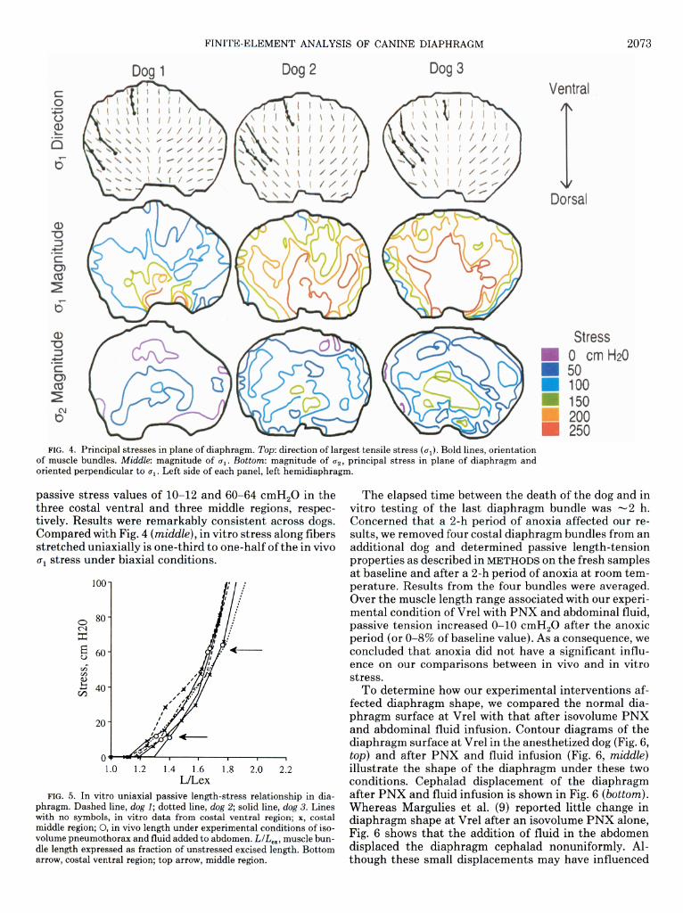
FINITE-ELEMENT ANALYSIS OF CANINE DIAPHRAGM 2073
Dog 1 Doa 1 Dog 2 Dog 3
Dorsal
Stress 0 cm Hz0
i 50 Ann
FIG. 4. Principal stresses m plane of diaphragm. Top: direction of largest tensile stress (ui). Bold lines, orientation of muscle bundles. Middle: magnitude of 0,. Bottom: magnitude of c2, principal stress in plane of diaphragm and oriented perpendicular to 0,. Left side of each panel, left hemidiaphragm.
passive stress values of lo-12 and 60-64 cmH,O in the three costal ventral and three middle regions, respec- tively. Results were remarkably consistent across dogs. Compared with Fig. 4 (middle), in vitro stress along fibers stretched uniaxially is one-third to one-half of the in vivo u1 stress under biaxial conditions.
100
1.0 1.2 1.4 1.6 1.8 2.0 2.2 L/Lex
FIG. 5. In vitro uniaxial passive length-stress relationship in dia- phragm. Dashed line, dog 1; dotted line, dog 2; solid line, dog 3. Lines with no symbols, in vitro data from costal ventral region; x, costal middle region; 0, in vivo length under experimental conditions of iso- volume pneumothorax and fluid added to abdomen. L/L,,, muscle bun- dle length expressed as fraction of unstressed excised length. Bottom arrow, costal ventral region; top arrow, middle region.
The elapsed time between the death of the dog and in vitro testing of the last diaphragm bundle was -2 h. Concerned that a 2-h period of anoxia affected our re- sults, we removed four costal diaphragm bundles from an additional dog and determined passive length-tension properties as described in METHODS on the fresh samples at baseline and after a 2-h period of anoxia at room tem- perature. Results from the four bundles were averaged. Over the muscle length range associated with our experi- mental condition of Vrel with PNX and abdominal fluid, passive tension increased O-10 cmH,O after the anoxic period (or O-8% of baseline value). As a consequence, we concluded that anoxia did not have a significant influ- ence on our comparisons between in vivo and in vitro stress.
To determine how our experimental interventions af- fected diaphragm shape, we compared the normal dia- phragm surface at Vrel with that after isovolume PNX and abdominal fluid infusion. Contour diagrams of the diaphragm surface at Vrel in the anesthetized dog (Fig. 6, top) and after PNX and fluid infusion (Fig. 6, middle) illustrate the shape of the diaphragm under these two conditions. Cephalad displacement of the diaphragm after PNX and fluid infusion is shown in Fig. 6 (bottom). Whereas Margulies et al. (9) reported little change in diaphragm shape at Vrel after an isovolume PNX alone, Fig. 6 shows that the addition of fluid in the abdomen displaced the diaphragm cephalad nonuniformly. Al- though these small displacements may have influenced

2074 FINITE-ELEMENT ANALYSIS OF CANINE DIAPHRAGM
Dog 1 Dog 2
Anesthetized
PNX and F
Dog 3
Ventral
1
Dorsal
Cephalad Displacement
0 -0.3 - 0.0 cm
FIG. 6. Contour diagrams of canine diaphragm at relaxation volume. Top, anesthetized condition; middle, after induction of isovolume pneumothorax and addition of 500 ml Ringer solution to abdomen (PNX & F); bottom, cephalad displacement of diaphragm from anesthetized to PNX & F condition. Solid lines, outlines of diaphragm in series of 1.39-mm-thick transverse planes with a 0.7 cm separation; dashed line, level of reference location on spine that remains stationary.
the stress distributions shown in Fig. 4, the advantage of studying the diaphragm after PNX and fluid infusion was that the Pdi distribution could be precisely evaluated over the diaphragm surface.
DISCUSSION
In summary, our results show that 1) diaphragm stress is nonuniform and anisotropic (i.e., varies both with lo- cation on the diaphragm surface and direction), 2) the largest stress (al) is aligned with the muscle bundles and is two to four times larger than CQ (perpendicular to g1 in diaphragm plane), and 3) stress along the muscle bundle is larger in vivo under conditions of biaxial stress than at the same length in vitro under uniaxial stress.
In the finite-element analysis, the applied load to the diaphragm was approximated by a Pdi gradient distrib- uted over its surface. In reality, there are additional local forces acting on the diaphragm where it is attached to the mediastinum, v .ena cava, and liver. These attachments produced small focal irregularities in the diaphragm shape and may account for the minor left-to-right asym- metry in diaphragm stress in Fig. 4. However, there are no apparent gross discontinuities in the stress computed in these regions.
In our analysis we treated the diaphragm as a mem- brane of uniform thickness. In truth, its thickness is non- uniform. After correction for thickness, the actual stress experienced by the central tendon would be much higher than in the thicker muscular regions. Regional dia- phragm thickness variations have been reported by Mar-
gulies (7) and Brancatisano et al. (1). Even though stresses would be expected to be higher in the thinner more dorsal regions of the costal diaphragm, these re- gions reside in the dorsal zone of apposition and were not considered in the finite-element analysis. No significant differences in the thickness of the regions apposed to the PNX (Fig. 4, top) were found (7). Furthermore, the thick- ness in these regions of the diaphragm muscle is -2.5 mm (7), the thickness used in the finite-element analysis. Therefore, the stresses shown in Fig. 4 are representative of the actual stresses in the muscular region of the dia- phragm. Stresses along and across the muscle bundles in the ventral region tend to be lower than in the more dor- sal regions of the diaphragm studied.
Many investigators have reported estimates of dia- phragm tension rather than stress. To facilitate compari- son between this study and published observations, it is convenient to compute tension from our stress measure- ments. Diaphragm tension is equal to stress in the plane of the diaphragm multiplied by diaphragm thickness. In this analysis, because the diaphragm was considered to have uniform thickness (0.25 cm), tension (in units of g/cm) would be equal to 0.25 times the stresses shown in Fig. 4. A major finding of this study is that tension in the diaphragm is nonuniform and anisotropic. In other words, tension varies with diaphragm region and direc- tion, with the largest tensile forces oriented parallel to the fibers in the muscular region of the diaphragm. Pas- sive diaphragm tension is -35-60 g/cm along the muscle fibers and -10-25 g/cm across the fibers in the plane of the supine dog diaphragm.
Other investigators have estimated passive tension in

FINITE-ELEMENT ANALYSIS OF CANINE DIAPHRAGM 2075
the human diaphragm at Vrel by measuring the shape of The authors thank Daniel Olson for reconstructing the DSR images,
the diaphragm from X-ray projections, making assump- Dr. Edmund Chao for allowing us to use the Biomechanics Computer
tions about the Pdi gradient and using the Laplace rela- Facility for the finite-element simulations, and Ji Qing Zhen for assis-
tionship. Tension was assumed to be uniform and isotro- tance on a portion of the finite-element analysis.
pit in each study. Smith and Loring (11) estimated ten- This work was supported by National Heart, Lung, and Blood Insti-
- tute Grants HL-04664 and HL-46230; the American Lung Association;
sions of 5 and 46 g/cm in the upright and supine postures, and the Whitaker Foundation.
respectively. Whitelaw et al. (15) calculated tensions of Address for reprint requests: S. S. Margulies, Dept. of Bioengineer-
lo-20 g/cm in upright individuals (assuming units in ing, 105 Hayden Hall, Univ. of Pennsylvania, Philadelphia, PA 19104- 6392 .
their Table 1 to be g/cm). More recently Paiva et al. (10) estimated tensions of 32-54 g/cm in supine humans. The Received 11 January 1993; accepted in final form 20 December 1993.
uniform tension values for supine humans are in agree- ment with the average of tension measured along and REFERENCES across the muscle fibers in the supine dog diaphragm. In addition, the present study provides more detailed infor-
1. Brancatisano, A., T. C. Amis, A. Tully, W. T. Kelly, and L. A. Engel. Regional distribution of blood flow within the dia- phragm. J. Appl. Physiol. 71: 583~589,199l. Farkas, G. A., and D. F. Rochester. Functional characteristics of canine costal and crural diaphragm. J. Appl. Physiol. 65: 2253- 2260,1988. Fung, Y. C. A First Course in Continuum Mechanics (2nd ed.). Englewood Cliffs, NJ: Prentice-Hall, 1977. Hoffman, E. A., and R. L. Ritman. Effect of body orientation on regional lung expansion in dog and sloth. J. Appl. Physiol. 59: 468- 480,1985. Kim, M. J., W. S. Druz, J. Danon, W. Machnach, and J. T. Sharp. Mechanics of the canine diaphragm. J. AppZ. Physiol. 41: 369-382,1976. Krayer, S., K. Rehder, J. Vettermann, E. P. Didier, and E. L. Ritman. Position and motion of the human diaphragm dur- ing anesthesia-paralysis. Anesthesiology 70: 891-898, 1989. Margulies, S. S. Variation in canine diaphragm thickness. J. AppZ. Physiol. 70: 2663-2668, 1991. Margulies, S. S., G. A. Farkas, and J. R. Rodarte. Effects of body position and lung volume on in situ operating length of canine diaphragm. J. AppZ. Physiol. 69: 1702-1708,199O. Margulies, S. S., J. R. Rodarte, Jr., and E. A. Hoffman. Shape of the chest wall in the prone and supine anesthetized dog. J. AppZ. Physiol. 68: 1970-1978, 1990. Paiva, M., S. Verbanck, M. Estenne, B. Poncelet, C. Sege- barth, and P. T. Macklem. Mechanical implications of in vivo human diaphragm shape. J. AppZ. Physiol. 72: 1407-1412,1992. Smith, J. C., and S. H. Loring. Passive mechanical properties of the chest wall. In: Handbook of Physiology. The Respiratory System. Mechanics of Breathing. Bethesda, MD: Am. Physiol. Sot., 1986, sect. 3, vol. III, pt. 2, chapt. 25, p. 429-442. Sprung, J., C. Deschamps, S. S. Margulies, R. D. Hubmayr, and J. R. Rodarte. Effect of body position on regional diaphragm function in dogs. J. AppZ. Physiol. 68: 2296-2302, 1990. Timoshenko, S., and S. Woinowsky-Krieger. Theory of Plates and Shells. New York: McGraw-Hill, 1959. Whitelaw, W. A. Shape and size of the human diaphragm in vivo. J. AppZ. Physiol. 62: 180-186, 1987. Whitelaw, W. A., L. E. Hajdo, and J. A. Wallace. Relation- ships among pressure, tension, and shape of the diaphragm. J. AmZ. Physiol. 55: 1899-1905. 1983.
mation regarding the magnitude along and across the muscle fibers
of tension or stress 2.
Most materials require a larger tensile force to hold a sample at a given stretched length when there is an addi- tiona 1 tensile force acting perpendicular than under uni- axial conditions where the perpendicular direction is un-
3.
4.
restrained (3). use more force
For example, an to pull a sheet of
individual elastic to a
would have to given length if 5.
someone were sim ultan .eousl .y pulling the shee t wider. Thus, ou .r findi rigs that, for a given fibe r len &h, S tresses 6. are two- to threefold larger along fibers under biaxial vs. uni axial conditions were not surprisin .g. These results serve as a caution to those investigators who are tempted 7.
8. to extend uniaxial measurements to the biaxial loading conditions under w phich the diaphragm fu nctions in vivo.
Understanding phragm operates
the mechanical milieu in which the dia- situ is crucial to link contractility 9. in
information measured in vitro (under uniaxial condi- tions) to more physiological conditions where the dia- phragm operates under biaxial stress. Unfortunately, the diaphragm is not a hemisphere but has a radius of curva- ture that varies with position and orientation. A com- plete mechanical analysis requ .ires knowledge o f the de- taile Id geometry, including principal radii of curvature and tensions, an .d the material properties of diaphragm muscle and ten tral tendon. The present study illustrates the complexity of the state of passive tension in the dia- phragm and confirms the intuitively logical, but hereto- fore undemonstrated, fact that the predominant tension in the muscle is oriented along the muscle bundles. How-
10.
11.
12.
13.
14.
15. ever, unlike most other skeletal muscles, the bears some tension across the fibers as well.
diaphragm