Embed Size (px)
Citation preview

IJRERD
International Journal of Recent Engineering Research and Development (IJRERD)
ISSN: 2455-8761
www.ijrerd.com || Volume 02 – Issue 09 || September 2017 || PP. 68-79
68 | P a g e www.ijrerd.com
Finite Element Analysis of Tubesheet of WHRB Using ASME
Acceptance Criteria And UHX 13.4 Method
Raj Kumar Kushwaha1, Niranjan L. Shegokar
2
1PG Student at Dr. D.Y. Patil School of Engineering &Technology, Lohegaon,Savitribai Phule Pune University,
Pune 412105, India 2Associate Professor at Dr. D.Y. Patil School of Engineering & Technology, Lohegaon Savitribai Phule Pune
University, Pune 412105, India
Abstract:Tube sheet is one of the important components of waste heat recovery boiler (WHRB), which
separates the tube side fluid and shell side fluid. Proper design of tubesheet is important for safe and reliable
operation of the boiler. Due to high pressure difference between shell side and tube side fluids, maximum failure
occurs at tube to tubesheet junction during the boiler operation. Finite element analysis (FEA) is an important
tool as it is not possible to study the combined effect of all the stresses analytically. This paper deals with finite
element analysis of the boiler and validation of the stresses with ASME standards for safe operation and using
UHX 13.4 for loading criteria. For this the 3D FEA geometry was modelled in Solidworks and imported in
ANSYS to perform the analysis and then the stresses were validated as per ASME Section VIII Div. 2. The
tubesheet and tube to tubesheet weld junction was found safe for operation under all the UHX 13.4 loading
cases.
Keywords:Tube Sheet, FEM, ASME, UHX 13.4, WHRB
1. Introduction
Tube sheet is the main part of a boiler acting as a physical barrier between the tube side fluid and the
shell side fluid. It is an integral part of the waste heat recovery boiler which uses the waste heat from a system,
to convert water into pressurized steam. This work mainly focuses on the tubesheet analysis for all the loading
cases, as from the studies it is seen that tubesheet is part where maximum stress are generated in the waste heat
boiler unit and failure in the majority of previous boilers has occurred in tubesheet. Also the qualification of the
tube to tubesheet junction weld strength is mandatory to ensure that no failure occurs at this weld junction
during the boiler operation. This qualification in this work is done as per UHX-13.4 of ASME Sec. VIII Div. 1.
The finite element analysis scope is to analyse and validate that all the stresses generated are under the
allowable limits, as per ASME standards.
The work done in this paper is a part of Thermax Ltd, Pune Company project. The design and analysis
is done as per the client’s specifications and requirements.
2. Literature Review
The failure of tubesheet to tube joint is very common in industries. Therefore, the joint strength affects the
safety and the reliability of process plants directly. The results obtained from finite element analyses and
experiments presented by different references had mainly focused on the stresses in the various zones of
tubesheet and the tube to tubesheet joint.
The fatigue strength of tube-to-tubesheet welded joints under cyclic loading was studied by Wenxien
Su NingMaa, Zhifu Sang and G.E.O. Widera [1] they concluded that the key of the process of fabricating heat
exchanger is the joint of tube-to-tubesheet of heat exchanger and in their experiments all the specimens of
welded tube-to-tubesheet produce fatigue rupture in the zone of weld.
Weiya Jin, ZengliangGao et al. [2] did a comparison of two finite element models for calculating
stresses in shell-and-tube heat exchanger. In model I Traditional theory of elastic foundation model is used for
tubesheet to tube load share. Pipe elements are used to represent actual load and stress sharing between
tubesheet and tube in model II. As tubesheet and tubes are very heavy components for FEA modelling, so for
ease of solving and simplification within more reasonable time for analysis, they replaced tubes by elements of
different kind like beams, bars etc. as because of the tube hole, the perforated plate is weakened they simplified
as a solid plate which with the same diameter and thickness of the perforated plate with and an effective
Poisson’s ratio and an effective Young’s modulus. By their results they concluded that model I is more suitable
and justifies the actual working condition.
Hongjie Yu et al. [3] investigated the mechanical study on a fixed tubesheet using FEA, which are
welded with tube bundles and equipment shell using finite element method. They studied the effects of number

IJRERD
International Journal of Recent Engineering Research and Development (IJRERD)
ISSN: 2455-8761
www.ijrerd.com || Volume 02 – Issue 09 || September 2017 || PP. 68-79
69 | P a g e www.ijrerd.com
of tubes on the strength of tubesheet. Variation of the distributions and magnitudes of the stress and deflection
of the tubesheet with the size of the unpierced part of the tubesheet were investigated. They created the finite
element model using the Ansys and plotted the results for stress intensity distribution on the tubesheet &
deflection of the tubesheet. They also performed the analysis of the tubesheet centrally supported with tubes.
Their results showed that with support of tubes the tubesheet did not behaved as a flat solid plate in terms of the
deflection and stress distribution features. Mainly, when the tubesheet is partly supported with the tubes in the
centre, the maximum stress intensity occurs at the point which depends on the size of the imperforated region
and the maximum deflection was near the unpierced region.
Zhao Jianping and Li Guo [4] studied a fixed tubesheet heat exchanger with a central pipe using finite element
analysis, whose diameter was greater than other heat exchanger tubes. A central hole in tubesheet will weaken
the stiffness and intensity of the tubesheet and cause local stress concentration along the central hole’s edge.
They found that the most dangerous place on the tubesheet was at the edge of tube distribution region.
From this study it is clearly seen that the most critical failure occurs in the tubesheet region of any heat
exchanger. Therefore, the stress validation in this region and tube to tubesheet weld qualification becomes
mandatory to ensure that the boiler will not fail during the operation.
3. Analysis Data The analysis data is acquired from the various sources for the materials used in the boiler construction
and there properties at the operation temperature from the ASME and ASME guidelines are followed for this
finite element analysis.
3.1 Material of Construction
Material properties at design temperature for the respective materials are used in the finite element
model are taken form Table TM-1 & 1A of ASME which are in Table 1 given below:
Table 1: Material Properties [5]
Part Material
Yield
Strength
(MPa)
Tensile
Strength
(MPa)
Design
Temp.
(°C)
Modulus of Elasticity (MPa)
at Design temperature
Allowable
Stress (MPa)
At Design
Temp.
Tubesheet/Shell SA 516M
Gr.485 260 485 260 1.88E+5 137.59
Tubes SA 179M 180 325 343 1.79E+05 88.56
3.2 Corrosion Allowance
The finite element analysis is performed in the corroded condition of the boiler which will be the
minimum thickness after the corrosion. Corrosion allowance of 1.6 mm is applicable on the shell side surfaces
and corrosion allowance of 3.2 mm is applicable on the tube side surfaces [6].
3.3 Design Considerations as per UHX-13.4
It is generally not possible to determine, by observation, the most severe loading conditions which may
cause a breakdown of boiler. So, it is necessary to perform the finite element analysis considering all the design
and operating loading cases for various load conditions. As per UHX-13.4 of ASME guidelines following cases
are considered for the analysis at the Maximum Allowable Working Pressure (MAWP) of the boiler, as given in
table 2 [7].
Table 2: Load Cases for FEA
MAWP LC 1 LC 2 LC 3 LC 4
TUBE SIDE 0.49327 MPa -0.101325 MPa 0.49327 MPa -0.101325 MPa
SHELL SIDE -0.101325 MPa 1.15522 MPa 1.15522 MPa -0.101325 MPa
IJRERD
International Journal of Recent Engineering Research and Development (IJRERD)
ISSN: 2455-8761
www.ijrerd.com || Volume 02 – Issue 09 || September 2017 || PP. 68-79
70 | P a g e www.ijrerd.com
As a conservative approach, maximum design pressure is replaced with maximum allowable working
pressure in FEA [8].
3.4 Compensating pressure for the channel openings
As we have not modelled complete WHRB unit, the internal pressure causes thrust at opening where
the model is not constrained in the axial direction. So, to keep the model in static equilibrium compensation
pressure is applied at the opening which is given by the equation (I) which is derived using basic engineering –
𝑃𝑐 = −𝑃𝑖
𝐷𝑜
𝐷𝑖
2
− 1𝐸𝑞. (𝐼)
Where, Pc = Compensation pressure
Pi = Internal pressure (Tube side MAWP)
Do = Outer diameter of channel opening
Di = Inner Diameter of the channel Opening
Table 3 shows the calculated values of compensation pressure using the above equation.
Table 3: Compensating pressure for the channel opening
Internal Pressure Outer Dia. of Channel Opening Inner Dia. of Channel Opening Pc
0.49327 3590.00 3556.40 -25.9824
-0.101325 3590.00 3556.40 5.3372
4. Finite Element Analysis 4.1 SolidModelling
The CAD model of the WHRB was prepared in Solidworks 2016 in the corroded condition as shown in
figure, 1 and was imported in Ansys 18.0 for the FEA. All the dimensions were as per the final released
drawings [6] of the WHRB by Thermax. As the detailed drawings are the confidential part of a company, they
cannot be included in this paper, the overall bounding box dimension for the solid modelled unit is 6850mm ×
3632mm × 3632mm.
Figure 1: CAD Model of WHRB unit
IJRERD
International Journal of Recent Engineering Research and Development (IJRERD)
ISSN: 2455-8761
www.ijrerd.com || Volume 02 – Issue 09 || September 2017 || PP. 68-79
71 | P a g e www.ijrerd.com
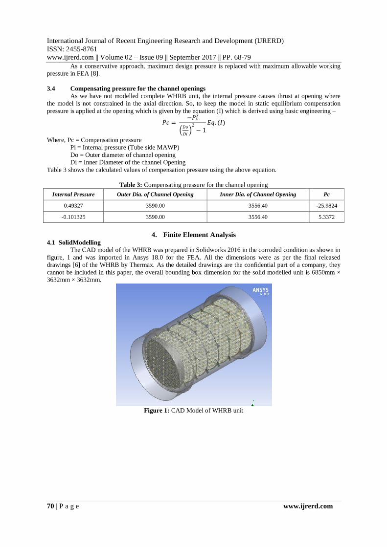
For reducing the number of elements and ease of analysis symmetry is applied in Ansys, figure 2
shows the CAD model after applying symmetry on XZ axis and YZ axis.
Figure 2: Symmetric model
4.2 Contact Definition
Defining the contacts is one of the major parameter of the structural analysis. The behaviour of the
various parts in the assembly is solely dependent on the contact definition. The contacts in WHRB assembly are
defined understanding the actual nature of working of the components.
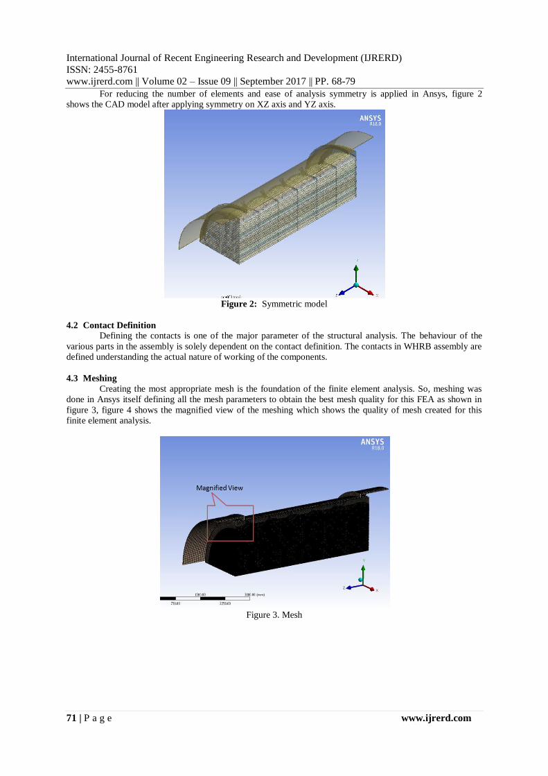
4.3 Meshing
Creating the most appropriate mesh is the foundation of the finite element analysis. So, meshing was
done in Ansys itself defining all the mesh parameters to obtain the best mesh quality for this FEA as shown in
figure 3, figure 4 shows the magnified view of the meshing which shows the quality of mesh created for this
finite element analysis.
Figure 3. Mesh

IJRERD
International Journal of Recent Engineering Research and Development (IJRERD)
ISSN: 2455-8761
www.ijrerd.com || Volume 02 – Issue 09 || September 2017 || PP. 68-79
72 | P a g e www.ijrerd.com
Figure 4: Mesh (Magnified View)
4.4 Boundary Conditions
The model is constraint with the following parameters to match the boundary conditions of real time
situation. And then the various pressure conditions are applied for each load case and the solution is obtained.
The figures 5(a) and 5(b) show the model constraints which are common for all the load conditions to be solved.
Figure 5(a): Model Constraint
Figure 5(b): Model Constraint
IJRERD
International Journal of Recent Engineering Research and Development (IJRERD)
ISSN: 2455-8761
www.ijrerd.com || Volume 02 – Issue 09 || September 2017 || PP. 68-79
73 | P a g e www.ijrerd.com
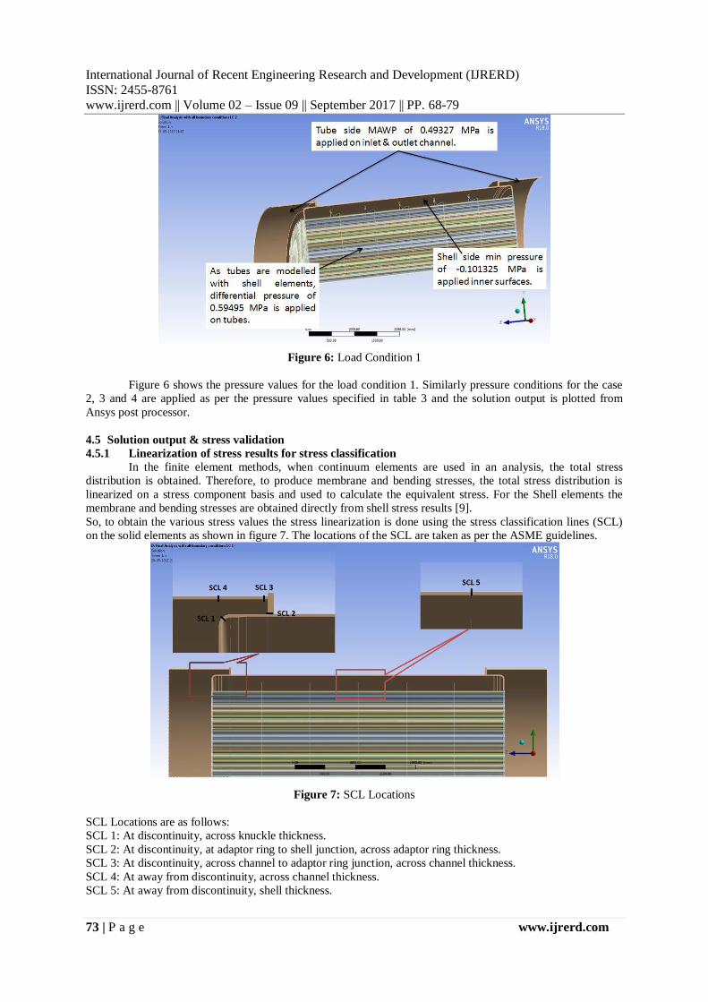
Figure 6: Load Condition 1
Figure 6 shows the pressure values for the load condition 1. Similarly pressure conditions for the case
2, 3 and 4 are applied as per the pressure values specified in table 3 and the solution output is plotted from
Ansys post processor.
4.5 Solution output & stress validation
4.5.1 Linearization of stress results for stress classification
In the finite element methods, when continuum elements are used in an analysis, the total stress
distribution is obtained. Therefore, to produce membrane and bending stresses, the total stress distribution is
linearized on a stress component basis and used to calculate the equivalent stress. For the Shell elements the
membrane and bending stresses are obtained directly from shell stress results [9].
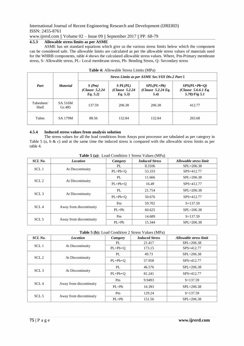
So, to obtain the various stress values the stress linearization is done using the stress classification lines (SCL)
on the solid elements as shown in figure 7. The locations of the SCL are taken as per the ASME guidelines.
Figure 7: SCL Locations
SCL Locations are as follows:
SCL 1: At discontinuity, across knuckle thickness.
SCL 2: At discontinuity, at adaptor ring to shell junction, across adaptor ring thickness.
SCL 3: At discontinuity, across channel to adaptor ring junction, across channel thickness.
SCL 4: At away from discontinuity, across channel thickness.
SCL 5: At away from discontinuity, shell thickness.

IJRERD
International Journal of Recent Engineering Research and Development (IJRERD)
ISSN: 2455-8761
www.ijrerd.com || Volume 02 – Issue 09 || September 2017 || PP. 68-79
74 | P a g e www.ijrerd.com
4.5.2 SCL stress plot from Ansys post processor:
All the SCL plot results are taken as it is from the ansys post processor after the FEA solution. In all
the SCL plots (figure 8a, 8b, 8c, 8d & 8e), X-axis shows the across thickness at the stress linearization path (in
mm) and Y-axis shows the induced stress values (in MPa), red dots are membrane stress values and orange dots
are combined stress values as per plot definition.
Figure 8(a): SCL 1 Plot
Figure 8(b): SCL 2 Plot Figure 8(c): SCL 3 Plot
Figure 8(d): SCL 4 Plot Figure 8(e): SCL 5 Plot
The above SCL plots show the stress values for the load condition 1. Similarly, SCL plots are obtained
from Ansys solution output and the stress values are tabulated, which are in table 5a, 5b and 5c.
IJRERD
International Journal of Recent Engineering Research and Development (IJRERD)
ISSN: 2455-8761
www.ijrerd.com || Volume 02 – Issue 09 || September 2017 || PP. 68-79
75 | P a g e www.ijrerd.com
4.5.3 Allowable stress limits as per ASME
ASME has set standard equations which give us the various stress limits below which the component
can be considered safe. The allowable limits are calculated as per the allowable stress values of materials used
for the WHRB components, table 4 shows the calculated allowable stress values. Where, Pm-Primary membrane
stress, S- Allowable stress, PL- Local membrane stress, Pb- Bending Stress, Q- Secondary stress
Table 4: Allowable Stress Limits (MPa)
Part Material
Stress Limits as per ASME Sec.VIII Div.2 Part 5
S (Pm)
(Clause 5.2.24
Eq. 5.2)
S PL(PL)
(Clause 5.2.24
Eq. 5.3)
SPL(PL+Pb)
(Clause 5.2.24 Eq.
5.4)
SPS(PL+Pb+Q)
(Clause 5.6.6.1 Eq.
5.78)/Fig 5.1
Tubesheet/ Shell
SA 516M Gr.485
137.59 206.38 206.38 412.77
Tubes SA 179M 88.56 132.84 132.84 265.68
4.5.4 Induced stress values from analysis solution
The stress values for all the load conditions from Ansys post processor are tabulated as per category in
Table 5 (a, b & c) and at the same time the induced stress is compared with the allowable stress limits as per
table 4.
Table 5 (a): Load Condition 1 Stress Values (MPa)
SCL No. Location Category Induced Stress Allowable stress limit
SCL 1 At Discontinuity PL 8.3106 SPL=206.38
PL+Pb+Q 53.333 SPS=412.77
SCL 2 At Discontinuity PL 11.666 SPL=206.38
PL+Pb+Q 16.49 SPS=412.77
SCL 3 At Discontinuity PL 21.754 SPL=206.38
PL+Pb+Q 50.676 SPS=412.77
SCL 4 Away from discontinuity Pm 59.702 S=137.59
PL+Pb 60.625 SPL=206.38
SCL 5 Away from discontinuity Pm 14.689 S=137.59
PL+Pb 15.344 SPL=206.38
Table 5 (b): Load Condition 2 Stress Values (MPa)
SCL No. Location Category Induced Stress Allowable stress limit
SCL 1 At Discontinuity PL 21.417 SPL=206.38
PL+Pb+Q 173.15 SPS=412.77
SCL 2 At Discontinuity PL 49.73 SPL=206.38
PL+Pb+Q 57.958 SPS=412.77
SCL 3 At Discontinuity PL 46.576 SPL=206.38
PL+Pb+Q 81.241 SPS=412.77
SCL 4 Away from discontinuity Pm 9.9493 S=137.59
PL+Pb 16.393 SPL=206.38
SCL 5 Away from discontinuity Pm 129.24 S=137.59
PL+Pb 151.56 SPL=206.38

IJRERD
International Journal of Recent Engineering Research and Development (IJRERD)
ISSN: 2455-8761
www.ijrerd.com || Volume 02 – Issue 09 || September 2017 || PP. 68-79
76 | P a g e www.ijrerd.com
Table 5 (c): Load Condition 3 Stress Values (MPa)
SCL No. Location Category Induced Stress Allowable stress limit
SCL 1 At Discontinuity PL 15.67 SPL=206.38
PL+Pb+Q 149.63 SPS=412.77
SCL 2 At Discontinuity PL 62.842 SPL=206.38
PL+Pb+Q 83.186 SPS=412.77
SCL 3 At Discontinuity PL 110.6 SPL=206.38
PL+Pb+Q 297.94 SPS=412.77
SCL 4 Away from discontinuity Pm 78.956 S=137.59
PL+Pb 91.176 SPL=206.38
SCL 5 Away from discontinuity Pm 126.68 S=137.59
PL+Pb 170.86 SPL=206.38
For Load condition 4, thetotal induced equivalent stresses 72.92 MPa (figure 9) is much less than the minimum
allowable stress value 88.38, hence stress linearization is not done for this case [9].
Figure 9: Solution of load condition 4 (eq. stress)
4.5.5 Result Verification for the finite element analysis solution.
Results are verified for an induced stress value to shell side MAWP as follows,Stress in shell at away
from discontinuity at the inner surface is given by:
𝜎 = 𝑃 × 𝑎2
𝑏2 − 𝑎2 × 1 +
𝑏2
𝑎2 𝑒𝑞 (𝐼𝐼)
𝜎 = 135.082 MPa
Where, a= ID of the shell (3353.2mm),
b= OD of the shell (3382mm),
P= 1.15522 MPa (Load condition 3)
Equation (II) is the basic engineering equation for the stress calculation in the thick walled cylinder.
Here the cylinder is considered as a thick walled, as it is needed to study the value of stress across the wall
thickness i.e. the above calculated stress is at the inner surface of the shell wall.
The stress is plotted in the postprocessor solution of the analysis is 134.94 (figure 10) and they are matching
IJRERD
International Journal of Recent Engineering Research and Development (IJRERD)
ISSN: 2455-8761
www.ijrerd.com || Volume 02 – Issue 09 || September 2017 || PP. 68-79
77 | P a g e www.ijrerd.com
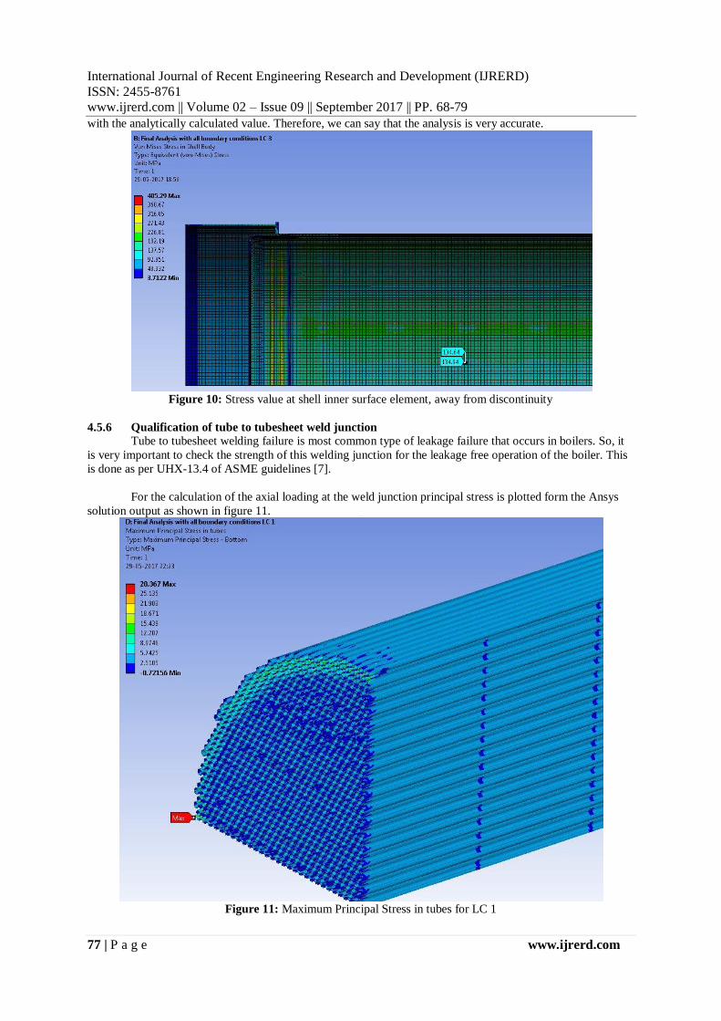
with the analytically calculated value. Therefore, we can say that the analysis is very accurate.
Figure 10: Stress value at shell inner surface element, away from discontinuity
4.5.6 Qualification of tube to tubesheet weld junction
Tube to tubesheet welding failure is most common type of leakage failure that occurs in boilers. So, it
is very important to check the strength of this welding junction for the leakage free operation of the boiler. This
is done as per UHX-13.4 of ASME guidelines [7].
For the calculation of the axial loading at the weld junction principal stress is plotted form the Ansys
solution output as shown in figure 11.
Figure 11: Maximum Principal Stress in tubes for LC 1
IJRERD
International Journal of Recent Engineering Research and Development (IJRERD)
ISSN: 2455-8761
www.ijrerd.com || Volume 02 – Issue 09 || September 2017 || PP. 68-79
78 | P a g e www.ijrerd.com
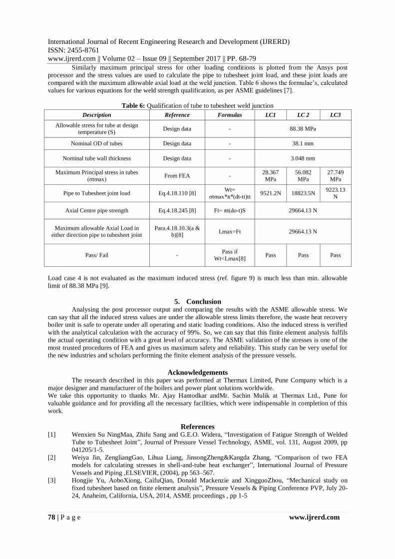
Similarly maximum principal stress for other loading conditions is plotted from the Ansys post
processor and the stress values are used to calculate the pipe to tubesheet joint load, and these joint loads are
compared with the maximum allowable axial load at the weld junction. Table 6 shows the formulae’s, calculated
values for various equations for the weld strength qualification, as per ASME guidelines [7].
Table 6: Qualification of tube to tubesheet weld junction
Description Reference Formulas LC1 LC 2 LC3
Allowable stress for tube at design temperature (S)
Design data - 88.38 MPa
Nominal OD of tubes Design data - 38.1 mm
Nominal tube wall thickness Design data - 3.048 mm
Maximum Principal stress in tubes
(σtmax) From FEA -
28.367
MPa
56.082
MPa
27.749
MPa
Pipe to Tubesheet joint load Eq.4.18.110 [8] Wt=
σtmax*π*(dt-tt)tt 9521.2N 18823.5N
9223.13
N
Axial Centre pipe strength Eq.4.18.245 [8] Ft= πt(do-t)S 29664.13 N
Maximum allowable Axial Load in either direction pipe to tubesheet joint
Para.4.18.10.3(a & b)[8]
Lmax=Ft 29664.13 N
Pass/ Fail - Pass if
Wt<Lmax[8] Pass Pass Pass
Load case 4 is not evaluated as the maximum induced stress (ref. figure 9) is much less than min. allowable
limit of 88.38 MPa [9].
5. Conclusion Analysing the post processor output and comparing the results with the ASME allowable stress. We
can say that all the induced stress values are under the allowable stress limits therefore, the waste heat recovery
boiler unit is safe to operate under all operating and static loading conditions. Also the induced stress is verified
with the analytical calculation with the accuracy of 99%. So, we can say that this finite element analysis fulfils
the actual operating condition with a great level of accuracy. The ASME validation of the stresses is one of the
most trusted procedures of FEA and gives us maximum safety and reliability. This study can be very useful for
the new industries and scholars performing the finite element analysis of the pressure vessels.
Acknowledgements
The research described in this paper was performed at Thermax Limited, Pune Company which is a
major designer and manufacturer of the boilers and power plant solutions worldwide.
We take this opportunity to thanks Mr. Ajay Hantodkar andMr. Sachin Mulik at Thermax Ltd., Pune for
valuable guidance and for providing all the necessary facilities, which were indispensable in completion of this
work.
References
[1] Wenxien Su NingMaa, Zhifu Sang and G.E.O. Widera, “Investigation of Fatigue Strength of Welded
Tube to Tubesheet Joint”, Journal of Pressure Vessel Technology, ASME, vol. 131, August 2009, pp
041205/1-5.
[2] Weiya Jin, ZengliangGao, Lihua Liang, JinsongZheng&Kangda Zhang, “Comparison of two FEA
models for calculating stresses in shell-and-tube heat exchanger”, International Journal of Pressure
Vessels and Piping ,ELSEVIER, (2004), pp 563–567.
[3] Hongjie Yu, AoboXiong, CaifuQian, Donald Mackenzie and XingguoZhou, “Mechanical study on
fixed tubesheet based on finite element analysis”, Pressure Vessels & Piping Conference PVP, July 20-
24, Anaheim, California, USA, 2014, ASME proceedings , pp 1-5

IJRERD
International Journal of Recent Engineering Research and Development (IJRERD)
ISSN: 2455-8761
www.ijrerd.com || Volume 02 – Issue 09 || September 2017 || PP. 68-79
79 | P a g e www.ijrerd.com
[4] Li Guo and Zhao Jianping, “Design by finite element analysis on tubesheet of heat exchanger with a
central hole”, Pressure Vessels & Piping Division Conference PVP2011 July 17-21, Baltimore,
Maryland, USA, 2011, ASME proceedings, pp 1-6
[5] ASME Boiler and Pressure Vessel Code, Section II, Part D (metric), 2015 Edition, The American
Society of Mechanical Engineers – New York, 10016,USA.
[6] Design data & geometric parameters are taken from Thermax Ltd. Pune, India
[7] ASME Boiler and Pressure Vessel Code, Section VIII, Div.1, 2015 Edition, The American Society of
Mechanical Engineers – New York, 10016,USA
[8] IBR 1950 with Latest Amendments. Boiler Division, Department Of Industrial Policy & Promotion,
Ministry Of Commerce & Industry, Government Of India, National Productivity Council,
UtpadktaBhawan, 5 – 6 Institutional Area, Lodi Road, New Delhi -110003,India.
[9] ASME Boiler and Pressure Vessel Code, Section VIII, Div.2, 2015 Edition, The American Society of
Mechanical Engineers – New York, 10016,USA
Author Profile RajKumar Kushwaha received the Diploma and B.E. degrees in MechanicalEngineering
fromMSBTE in 2012 and University of Pune 2015, respectively. From Oct-2016 to May-
2017, heworked atThermax Limited Company in Pune, India in Mechanical Engineering
Department where he studied the design, FEA, CFD analysis of various pressure vessels. He
is now perusing the last semester of Masters in Computer Aided Design, Manufacture &
Engineering, at Dr. D.Y. Patil School of Engineering& Technology under Savitribai Phule
Pune University (Formerly University of Pune)
Dr. Niranjan L. Shegokarreceived the Ph.D., M.E.(Design),B.E.(Mechanical) At present,
he is working as Dean (R&D) and Associate Professor in Mechanical Engineering
Department at Dr.D.Y. Patil School of Engineering and Technology, Lohegaon, Pune. He
has 15 years teaching experience and more than 22 publications in International Journal and
Conferences. His research area are Static and Dynamic FEM analysis of Composite and
FGM structures, Uncertainty analysis, Reliability analysis and fracture mechanics.