Embed Size (px)
Citation preview

Finite Element Analysis ofWrinkled Membrane Structures for
Sunshield Applications
Dr. John D. JohnstonMechanical Systems Analysis and Simulation Branch / Code 542
NASA Goddard Space Flight Center
2002 FEMCI WorkshopMay 23, 2002
(Based on a presentation at the 2002 AIAA Gossamer Spacecraft Forum)

May 23, 2002 2002 FEMCI Workshop 2
NGST Sunshield
• The Next Generation Space Telescope (NGST) requires a lightweight, deployable sunshield to provide passive cooling and straylight control.
• NGST ‘yardstick’ concept sunshield characteristics:– Central support structure– Deployable support booms– Pretensioned, thin-film
membranes

May 23, 2002 2002 FEMCI Workshop 3
1/10th Scale Model NGST Sunshield
Analysis and ground testing of a one-tenth scale model of the NGST ‘yardstick’ concept sunshield is
being carried out to develop and validate capabilities to predict and verify sunshield structural
characteristics.

May 23, 2002 2002 FEMCI Workshop 4
Sunshield Membrane Modeling
• A challenging aspect of sunshield analysis is modeling the nonlinear behavior of partially wrinkled, thin-film membranes.
• Modeling techniques previously used to model the NGST sunshield membranes:– Standard shell elements– Cable network method– Membrane elements with a ‘wrinkling’ material model
May 23, 2002 2002 FEMCI Workshop 5
Sunshield Membrane Modeling – cont.• Wrinkling material model:
– Finite element implementation of Stein-Hedgepeth wrinkling theory– Developed by Miller-Hedgepeth (1982) and Adler-Mikulas (2000)
• Membrane element stiffness iteratively modified to account for the effects of wrinkling: – Element state determined using a mixed stress-strain criteria:
• ? 2 > 0 ? taut• ?1 ? 0 ? slack
• ?1 > 0 and ? 2 ? 0 ? wrinkled
– Stiffness matrix formulation based on the element state:
? ?????
?
?
????
?
?
???
21
00
01
01
1 2 ??
?
?E
KTaut???
?
?
???
?
??
000000000
SlackK? ?
? ?
? ?? ?
angle stress principal sin2cos2
1120
012
4
???
???
?
?
???
?
??
??
???
QP
QQQPQP
EKWrinkled

May 23, 2002 2002 FEMCI Workshop 6
Finite Element Analysis
• The commercially available finite element analysis program ABAQUS is used to perform the analysis:– ABAQUS has robust nonlinear analysis capabilities.– ABAQUS user material (UMAT) subroutine feature allows for the
implementation of custom nonlinear constitutive relations.– Iterative Membrane Properties (IMP) UMAT subroutine developed by
Adler/University of Colorado-Boulder.
• The baseline structural analysis consists of several ABAQUS steps:– Step 1: Nonlinear static analysis – Initial preloading– Step 2: Nonlinear static analysis – Application of full preloads– Step 3: Modal analysis– Step 4: Frequency domain dynamic analysis
• Gravity and/or thermal loads may also be included in additional nonlinear static analysis steps.

May 23, 2002 2002 FEMCI Workshop 7
Finite Element Model
Membranes(4 Layers)
CentralBlock
TipMasses
(4 places)
Tapes/Cords
SpreaderBar
Membranes(4 layers)
Tip Mass
CFSLadder
Tube
• Finite element mesh:– 9505 nodes– 18005 elements
– Components:– Films = Membranes, Tapes, Cords– Support Structure = Central Block,
Tubes, Ladders, Spreader Bars– CFS (ABAQUS Pretension Sections)
May 23, 2002 2002 FEMCI Workshop 8
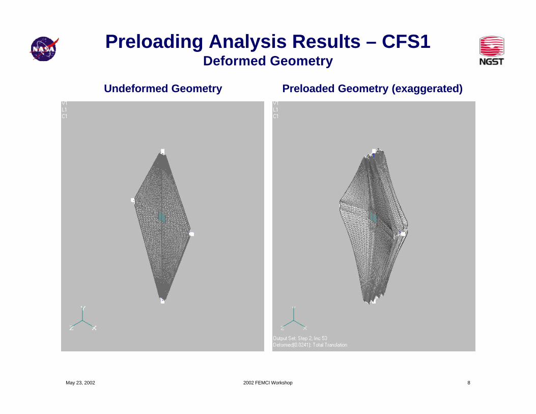
Preloading Analysis Results – CFS1Deformed Geometry
Undeformed Geometry Preloaded Geometry (exaggerated)

May 23, 2002 2002 FEMCI Workshop 9
Preloading Analysis Results – CFS1Principal Stresses and Wrinkle Region
Major Principal StressMax = 1.26E+6 Pa (191 psi)
Min = 7.60E+3 Pa (1 psi)
Minor Principal StressMax = 2.14E+5 Pa (31 psi)
Min = 0 Pa (0 psi)
Wrinkle Region73% of surface area is in
wrinkled region
NOTE: Results show are for outer membrane layer.Stresses and wrinkle region differ slightly for inner membrane layer.

May 23, 2002 2002 FEMCI Workshop 10
Dynamics Analysis Results – CFS1Mode # F (Hz) %RX
3 2.6716 8.17 2.8706 5.4
10 3.1271 6.816 3.2313 0.517 3.3673 15.620 3.4332 0.925 3.5376 10.227 3.6553 0.433 3.7026 6.635 3.764 3.745 3.8882 2.951 4.1214 0.454 4.138 0.667 4.214 0.473 4.2654 1.077 4.3458 3.582 4.7201 2.090 4.8813 0.894 5.0965 1.799 5.2261 0.4
102 5.3634 0.6110 5.5154 5.0112 5.5705 2.4114 5.6155 0.4120 5.7366 0.3123 5.7771 0.1126 5.8391 1.4138 5.9834 3.6150 6.2801 8.4162 6.5801 0.2186 6.9785 0.6
• Modal analysis predicts 347 modes in 0 – 10 Hz frequency range
– Lowest mode = 2.541 Hz (‘Twist’ mode of long side of membranes)
– 31 modes have EFFM-RX > 0.1% (account for 94% of the total mass)
0.1
1
10
100
0 2 4 6 8 10F (Hz)
Mag
nit
ud
e [m
/s^2
)/(m
/s^2
)]
Long
Medium
Short
3.37 Hz 3.54 Hz
5.52 Hz 6.28 Hz
2.67 Hz

May 23, 2002 2002 FEMCI Workshop 11
Preload Variation Study
Parameter CFS1 CFS2 CFS3# of Modes 347 278 184Total EFFM (%) 96 93 95F0 (Hz) 2.54 2.66 3.10F1 (Hz) 2.67 2.68 3.10FA (Hz) 2.54 2.66 3.12FB (Hz) 3.37 3.30 3.43
CFS1 = 1.425 N CFS2 = 2.848 N CFS3 = 4.272 N
F=3.37 Hz, EFFM=16% F=3.30 Hz, EFFM=39% F=3.43 Hz, EFFM=51%
Note:Mode 0: First mode
Mode 1: First significant modeMode A: Long side twist mode
Mode B: Mode w/ greatest EFFM
Mode Shapes For Dominant System Mode

May 23, 2002 2002 FEMCI Workshop 12
Modeling Technique Study
Mode Shapes For Dominant System Mode
Parameter Wrinkled Shell CableMembrane Network
# of Modes 347 156 103Total EFFM (%) 96 96 95F0 (Hz) 2.54 1.41 2.50F1 (Hz) 2.67 3.10 2.50FA (Hz) 2.54 2.86 2.64FB (Hz) 3.37 3.59 3.61
Note:Mode 0: First mode
Mode 1: First significant modeMode A: Long side twist mode
Mode B: Mode w/ greatest EFFM
Wrinkled MembraneFEM
Shell FEM Cable NetworkFEM
F=3.37 Hz, EFFM=16% F=3.59 Hz, EFFM=28% F=3.61 Hz, EFFM=47%
May 23, 2002 2002 FEMCI Workshop 13
+z+x
+y
TestStand
Sunshield
Shaker
1.5 m
1.5
m1.
9 m
3.4
m
+z+x
+y
+x
+y
TestStand
Sunshield
Shaker
1.5 m
1.5
m1.
9 m
3.4
m
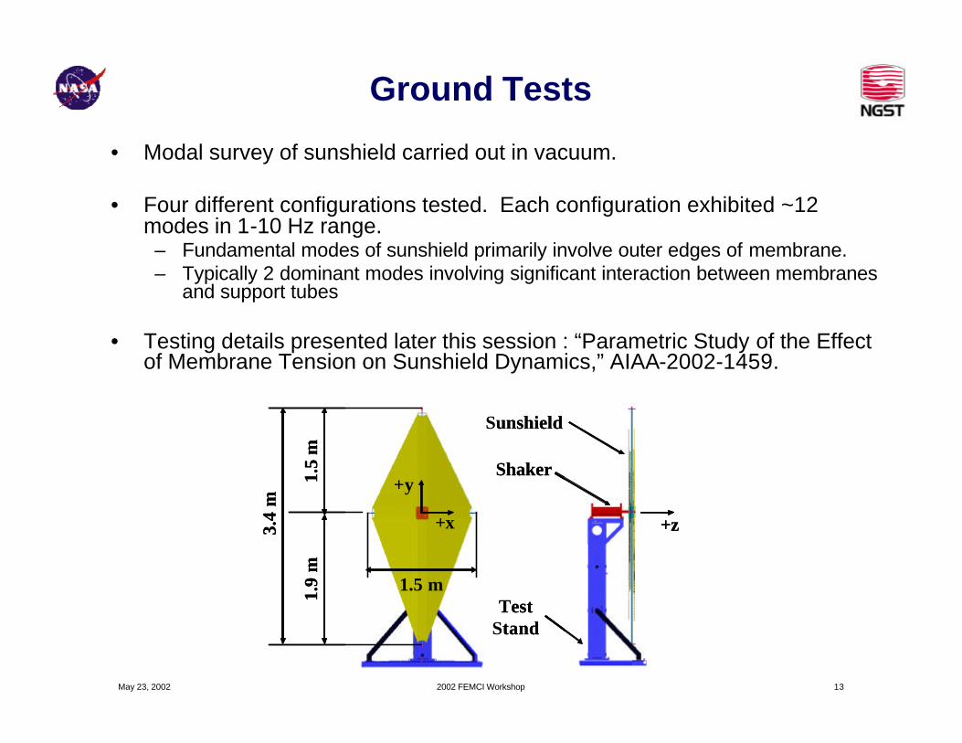
Ground Tests
• Modal survey of sunshield carried out in vacuum.
• Four different configurations tested. Each configuration exhibited ~12 modes in 1-10 Hz range.– Fundamental modes of sunshield primarily involve outer edges of membrane. – Typically 2 dominant modes involving significant interaction between membranes
and support tubes
• Testing details presented later this session : “Parametric Study of the Effect of Membrane Tension on Sunshield Dynamics,” AIAA-2002-1459.

May 23, 2002 2002 FEMCI Workshop 14
Comparison of Analysis and Ground TestsFrequencies
• Ground test analysis includes gravity loads and shaker support condition.
• Analysis / test correlation performed used modal assurance criteria (MAC) calculations from Dynaview software to identify mode pairs.
• In general, dominant system modes correlate better than low-frequency membrane modes.
Configuration Mode Analysis Test % DiffLT 3.77 3.63 -3.8MT 6.06 5.75 -5.4LT 3.71 3.43 -8.2MT 6.10 5.92 -3.1LT 3.57 3.35 -6.6MT 5.51 5.51 0.0LT 3.54 3.21 -10.3MT 6.36 5.83 -9.1LT 3.22 3.22 0.0MT 6.44 5.57 -15.6LT 3.55 3.21 -10.6MT 5.65 5.85 3.4
SS-CFS1-LSD
SS-CFS1-SSD
SS-CFS2-LSD
SS-CFS3-LSD
Tubes-LSD
Tubes-SSD

May 23, 2002 2002 FEMCI Workshop 15
Comparison of Analysis and Ground TestsMode Shapes
Test = 3.34 HzAnalysis = 3.57 Hz
-1
-0.8
-0.6
-0.4
-0.2
0
0.2
0.4
0.6
0.8
1
-0.5 0 0.5
-1.5
-1
-0.5
0
0.5
1
1.5Mode Shape
Dominant System Mode for CFS1 - Long Side Down Configuration
May 23, 2002 2002 FEMCI Workshop 16
Closing Remarks
• Finite element analysis was used to predict the structural dynamic behavior of a one-tenth scale model of the NGST ‘yardstick’ concept sunshield.– Membranes modeled using membrane elements in conjunction with a
‘wrinkling’ material model.– Comparison of analytical predictions and test results showed good
agreement for dominant system modes, but only fair agreement forfundamental membrane modes.
– Predictions from the wrinkled membrane model show better agreement with test results than shell element and cable network models.
• Current / Future Work:– Model updating study for one-tenth scale model sunshield.– Analytical/Experimental Study of Sunshield Membrane Wrinkling– Application of wrinkled membrane modeling technique to the study of
sunshield concepts developed by the NGST prime contractor.

May 23, 2002 2002 FEMCI Workshop 17
Sunshield Wrinkling Experiment
1/20th Scale Yardstick Sunshield Membrane
Test at James Madison University