Embed Size (px)
Citation preview
The Knee 21 (2014) 224–231
Contents lists available at ScienceDirect
The Knee
Finite element comparison of retrograde intramedullary nailing and locking platefixation with/without an intramedullary allograft for distal femur fracture followingtotal knee arthroplasty
Shih-Hao Chen a, Ming-Chieh Chiang b, Ching-Hua Hung b,⁎, Shang-Chih Lin c, Hsiao-Wei Chang b
a Department of Orthopedics, Tzu-Chi General Hospital at Taichung, and Tzu Chi University, Taiwanb Department of Mechanical Engineering, National Chiao Tung University, Hsinchu, Taiwanc Graduate Institute of Biomedical Engineering, National Taiwan University of Science and Technology, Taipei, Taiwan
⁎ Corresponding author at: National Chiao Tung Univ1001 University Road, Hsinchu, 30010, Taiwan. Tel.: +8
E-mail address: [email protected] (C.-H. Hu
0968-0160/$ – see front matter © 2013 Elsevier B.V. Allhttp://dx.doi.org/10.1016/j.knee.2013.03.006
a b s t r a c t
a r t i c l e i n f oArticle history:
Received 17 September 2012Received in revised form 3 March 2013Accepted 6 March 2013Keywords:Distal femur fractureKnee arthroplastyIntramedullaryRetrograde nailIntramedullary allograftOsteoporotic femur
Purpose: Periprosthetic distal femur fracture after total knee arthroplasty due to the stress-shielding phenom-enon is a challenging problem. Retrograde intramedullary nail (RIMN) or locking plate (LP) fixation with/without a strut allograft has been clinically used via less invasive stabilization surgery (LISS) for thetreatment of these periprosthetic fractures. However, their biomechanical differences in construct stabilityand implant stress have not been extensively studied, especially for the osteoporotic femur.Methods: This study used afinite-elementmethod to evaluate the differences betweenRIMN, LP, and LP/allograftfixation in treating periprosthetic distal femur fractures. There were sixteen variations of two fracture angles(transverse and oblique), two loading conditions (compression and rotation), and four bony conditions (onenormal and three osteoporotic). Construct stiffness, fracture micromotion, and implant stress were chosen asthe comparison indices.Results: The LP/allograft construct provides both lateral andmiddle supports to the displaced femur. Comparatively,
the LP and RIMN constructs, respectively, transmit the loads through the lateral and middle paths, thus providingmore unstable support to the construct and high stressing on the implants. The fracture pattern plays a minorrole in the construct stabilization of the three implants. In general, the biomechanical performances of the RIMNand LP constructs were comparable and significantly inferior to those of the LP/allograft construct. The bone qualityshould be evaluated prior to the selection of internal fixators.Conclusions: The LP/allograft construct significantly stabilizes the fracture gap, reduces the implant stress, andserves as the recommended fixation for periprosthetic distal femur fracture.© 2013 Elsevier B.V. All rights reserved.
1. Introduction
Distal femur fractures adjacent to total knee arthroplasty (TKA)present a rare and yet complex problem, with an incidence rangingfrom 0.3% to 2.5% after primary surgery and from 1.6% to 3.8% afterrevision surgery [1,2]. The occurrence of periprosthetic supracondylarfemur fractures can be attributed to the stress-shielding effectsaround the periprosthetic region [3–6]. Successful treatment requiresregaining a painless, well aligned knee with a satisfactory range ofmotion and maintaining good alignment of the entire lower limb.
A wide variety of orthopedic devices had been used for the internalfixation of these fractures including angled blade plates, dynamiccondylar plates, buttress plates, and flexible or rigid intramedullarynails [7]. Recently, periarticular locking plate (LP) or retrogradeintramedullary nail (RIMN) fixation has become a popular treatment
ersity Mechanical Engineering,86 3 571 2121 55160.ng).
rights reserved.
option with the less invasive stabilization system (LISS). The majoradvantage of LP is the ability to implant them with minimal softtissue dissection, periosteal stripping, and multiple fixed-anglescrews fixation around the fracture site to maintain distal fixation.Rigid RIMN can also be an effective device for minimally invasivestabilization of these fractures, and is considered if the patient hasan open box femoral component for device access and adequatedistal fracture fragments for locking fixation [8,9].
With unstable nail-bone contact, the construct stability of antegradenailing for a periprosthetic fracture is weaker than that of the lockingplate [10–12]. Comparatively, the retrograde nail makes deeper contactwith the subchondral bone and operates in aminimally invasive fashion[13]. Consequently, RIMN has been recommended as an alternative forthe treatment of periprosthetic fracture [14–17]. For LP fixation, themultiple points of cortical screws can provide better angular stabilityand secure bony anchoring for constructing stiffness and preservationof vascular supply [18–21]. However, the stress-shielding effect aroundthe periprosthetic region potentially makes proximal screw loosening amajor concern when using LISS plates [10–12,22,23]. Gardner et al. [24]
225S.-H. Chen et al. / The Knee 21 (2014) 224–231
used an intramedullary strut allograft to serve as the mechanical sup-port supplemented to the LISS plate (LP/allograft)fixation, and declaredthat the hybrid use of LP/allograft can significantly stabilize the con-struct and facilitate the bony union. However, the complication rate isstill 15–20% due to nonunion, malunion, infection, hardware failure ormortality even after RIMN or LP fixation for distal femur fractures fol-lowing TKA [16,17,20,22,24]. However, biomechanical comparisonsamong RIMN, LP, and LP/allograft have not been extensivelyinvestigated.
Therefore, this study used the finite-element method to comparethe construct behaviour subject to the variations of three internal fix-ations, two loading conditions, two fracture patterns, and four bonystrengths. The convergence and stiffness of the intact model was val-idated. Then, the construct behaviour was evaluated in terms of con-struct stiffness, fracture micromotion, and implant stress. Thepurposes of this study provide biomechanical information aboutthe differences among RIMN, LP, and LP/allograft, and point towhich one should be indicated individually for various types ofperiprosthetic fractures following TKA. This study hypothesized thatLP/allograft construct significantly stabilized fracture gap, reducedimplant stress, and is potentially suitable for the treatment ofperiprosthetic distal femur fracture with comminution, deficientbone stock, and severe osteoporosis.
2. Methods
This study used the abbreviations LP and RIMN to denote theperiarticular locking plate and retrograde intramedullary nail. TheLP, RIMN, and LP/allograft fixations were compared in terms of twofracture patterns: transverse (TP, TN, and TA) and oblique (OP, ON,and OA). The femoral strengths were simulated by the three osteopo-rotic conditions: ost-1 (mild), ost-2 (moderate), ost-3 (severe).
A B
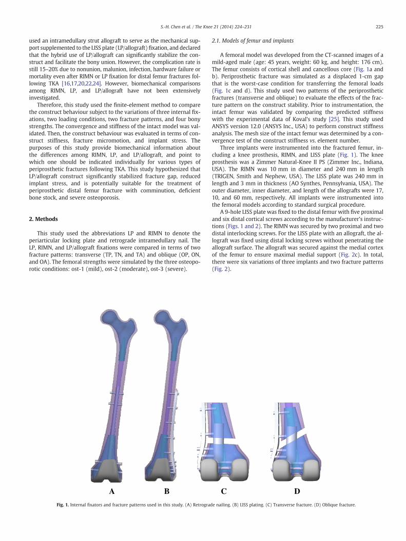
Fig. 1. Internal fixators and fracture patterns used in this study. (A) Retrograd
2.1. Models of femur and implants
A femoral model was developed from the CT-scanned images of amild-aged male (age: 45 years, weight: 60 kg, and height: 176 cm).The femur consists of cortical shell and cancellous core (Fig. 1a andb). Periprosthetic fracture was simulated as a displaced 1-cm gapthat is the worst-case condition for transferring the femoral loads(Fig. 1c and d). This study used two patterns of the periprostheticfractures (transverse and oblique) to evaluate the effects of the frac-ture pattern on the construct stability. Prior to instrumentation, theintact femur was validated by comparing the predicted stiffnesswith the experimental data of Koval’s study [25]. This study usedANSYS version 12.0 (ANSYS Inc., USA) to perform construct stiffnessanalysis. The mesh size of the intact femur was determined by a con-vergence test of the construct stiffness vs. element number.
Three implants were instrumented into the fractured femur, in-cluding a knee prosthesis, RIMN, and LISS plate (Fig. 1). The kneeprosthesis was a Zimmer Natural-Knee II PS (Zimmer Inc., Indiana,USA). The RIMN was 10 mm in diameter and 240 mm in length(TRIGEN, Smith and Nephew, USA). The LISS plate was 240 mm inlength and 3 mm in thickness (AO Synthes, Pennsylvania, USA). Theouter diameter, inner diameter, and length of the allografts were 17,10, and 60 mm, respectively. All implants were instrumented intothe femoral models according to standard surgical procedure.
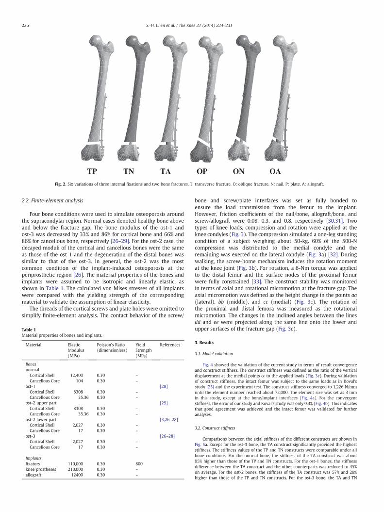
A 9-hole LISS plate was fixed to the distal femur with five proximaland six distal cortical screws according to the manufacturer’s instruc-tions (Figs. 1 and 2). The RIMN was secured by two proximal and twodistal interlocking screws. For the LISS plate with an allograft, the al-lograft was fixed using distal locking screws without penetrating theallograft surface. The allograft was secured against the medial cortexof the femur to ensure maximal medial support (Fig. 2c). In total,there were six variations of three implants and two fracture patterns(Fig. 2).
C D
e nailing. (B) LISS plating. (C) Transverse fracture. (D) Oblique fracture.
TN ONTP OPTA OA
Fig. 2. Six variations of three internal fixations and two bone fractures. T: transverse fracture. O: oblique fracture. N: nail. P: plate. A: allograft.
226 S.-H. Chen et al. / The Knee 21 (2014) 224–231
2.2. Finite-element analysis
Four bone conditions were used to simulate osteoporosis aroundthe supracondylar region. Normal cases denoted healthy bone aboveand below the fracture gap. The bone modulus of the ost-1 andost-3 was decreased by 33% and 86% for cortical bone and 66% and86% for cancellous bone, respectively [26–29]. For the ost-2 case, thedecayed moduli of the cortical and cancellous bones were the sameas those of the ost-1 and the degeneration of the distal bones wassimilar to that of the ost-3. In general, the ost-2 was the mostcommon condition of the implant-induced osteoporosis at theperiprosthetic region [26]. The material properties of the bones andimplants were assumed to be isotropic and linearly elastic, asshown in Table 1. The calculated von Mises stresses of all implantswere compared with the yielding strength of the correspondingmaterial to validate the assumption of linear elasticity.
The threads of the cortical screws and plate holes were omitted tosimplify finite-element analysis. The contact behavior of the screw/
Table 1Material properties of bones and implants.
Material ElasticModulus(MPa)
Poisson's Ratio(dimensionless)
YieldStrength(MPa)
References
Bonesnormal
Cortical Shell 12,400 0.30 –
Cancellous Core 104 0.30 –
ost-1 [29]Cortical Shell 8308 0.30 –
Cancellous Core 35.36 0.30 –
ost-2 upper part [29]Cortical Shell 8308 0.30 –
Cancellous Core 35.36 0.30 –
ost-2 lower part [3,26–28]Cortical Shell 2,027 0.30 –
Cancellous Core 17 0.30 –
ost-3 [26–28]Cortical Shell 2,027 0.30 –
Cancellous Core 17 0.30 –
Implantsfixators 110,000 0.30 800knee prostheses 210,000 0.30 –
allograft 12400 0.30 –
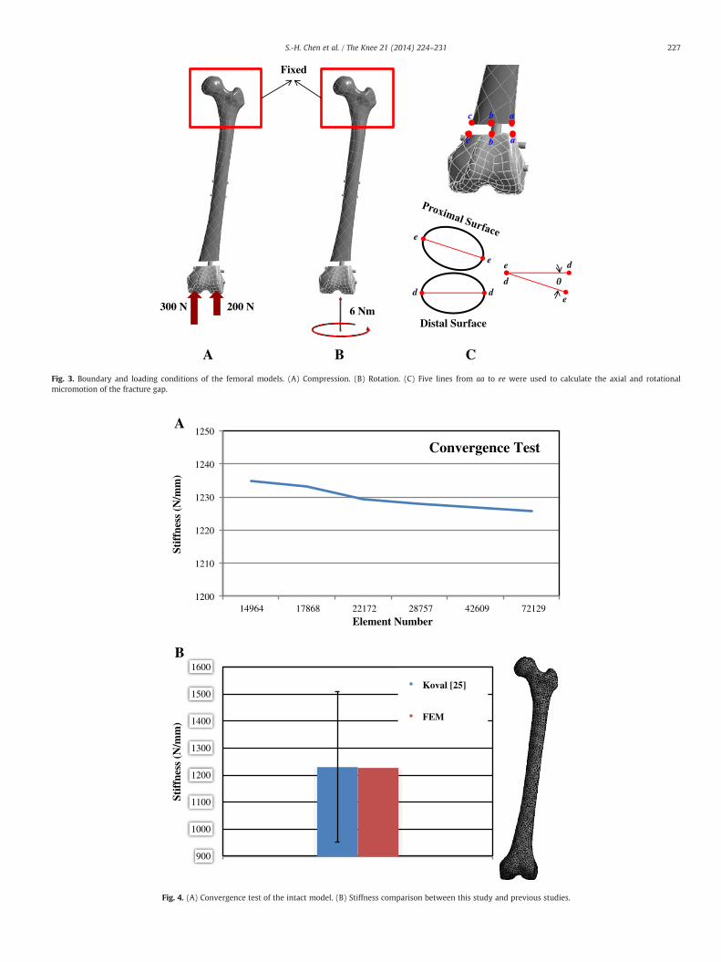
bone and screw/plate interfaces was set as fully bonded toensure the load transmission from the femur to the implant.However, friction coefficients of the nail/bone, allograft/bone, andscrew/allograft were 0.08, 0.3, and 0.8, respectively [30,31]. Twotypes of knee loads, compression and rotation were applied at theknee condyles (Fig. 3). The compression simulated a one-leg standingcondition of a subject weighing about 50-kg. 60% of the 500-Ncompression was distributed to the medial condyle and theremaining was exerted on the lateral condyle (Fig. 3a) [32]. Duringwalking, the screw-home mechanism induces the rotation momentat the knee joint (Fig. 3b). For rotation, a 6-Nm torque was appliedto the distal femur and the surface nodes of the proximal femurwere fully constrained [33]. The construct stability was monitoredin terms of axial and rotational micromotion at the fracture gap. Theaxial micromotion was defined as the height change in the points aa(lateral), bb (middle), and cc (medial) (Fig. 3c). The rotation ofthe proximal and distal femora was measured as the rotationalmicromotion. The changes in the inclined angles between the linesdd and ee were projected along the same line onto the lower andupper surfaces of the fracture gap (Fig. 3c).
3. Results
3.1. Model validation
Fig. 4 showed the validation of the current study in terms of result convergenceand construct stiffness. The construct stiffness was defined as the ratio of the verticaldisplacement at the medial points cc to the applied loads (Fig. 3c). During validationof construct stiffness, the intact femur was subject to the same loads as in Koval’sstudy [25] and the experiment test. The construct stiffness converged to 1,226 N/mmuntil the element number reached about 72,000. The element size was set as 3 mmin this study, except at the bone/implant interfaces (Fig. 4a). For the convergentstiffness, the error of our study and Koval’s study was only 0.3% (Fig. 4b). This indicatesthat good agreement was achieved and the intact femur was validated for furtheranalyses.
3.2. Construct stiffness
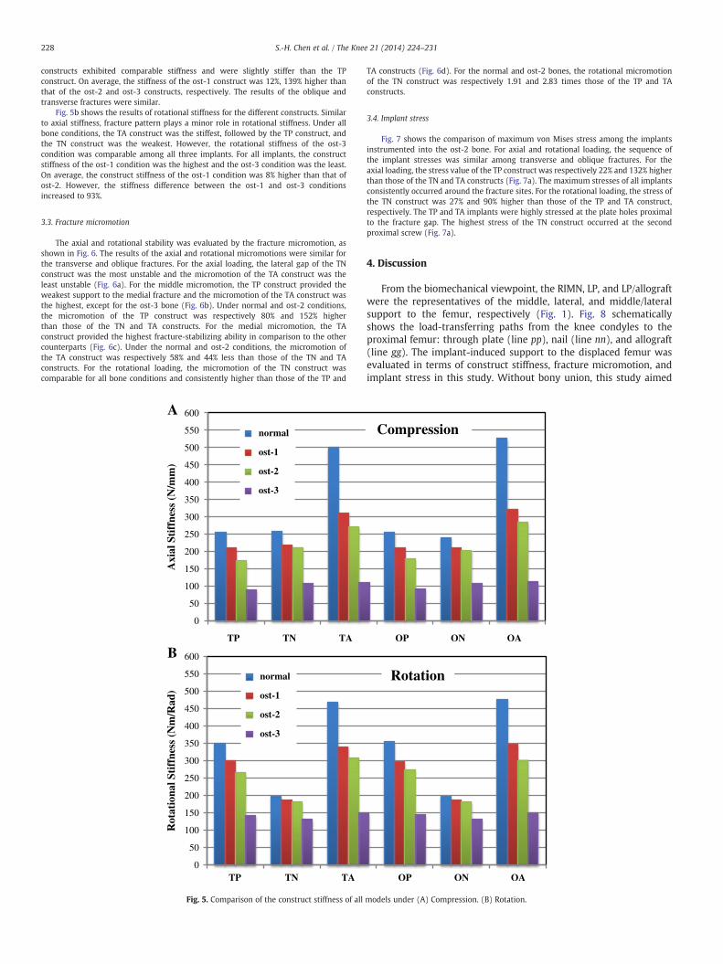
Comparisons between the axial stiffness of the different constructs are shown inFig. 5a. Except for the ost-3 bone, the TA construct significantly provided the higheststiffness. The stiffness values of the TP and TN constructs were comparable under allbone conditions. For the normal bone, the stiffness of the TA construct was about95% higher than those of the TP and TN constructs. For the ost-1 bones, the stiffnessdifference between the TA construct and the other counterparts was reduced to 45%on average. For the ost-2 bones, the stiffness of the TA construct was 57% and 29%higher than those of the TP and TN constructs. For the ost-3 bone, the TA and TN
A B
Fixed
200 N300 N 6 Nm
C
a
a
c
c
b
b
d d
e
e
Distal Surface
e
e
d
d
Fig. 3. Boundary and loading conditions of the femoral models. (A) Compression. (B) Rotation. (C) Five lines from aa to ee were used to calculate the axial and rotationalmicromotion of the fracture gap.
1200
1210
1220
1230
1240
1250
14964 17868 22172 28757 42609 72129
Stif
fnes
s (N
/mm
)
Element Number
Convergence Test
900
1000
1100
1200
1300
1400
1500
1600
Stif
fnes
s (N
/mm
)
Koval [25]
FEM
A
B
Fig. 4. (A) Convergence test of the intact model. (B) Stiffness comparison between this study and previous studies.
227S.-H. Chen et al. / The Knee 21 (2014) 224–231
228 S.-H. Chen et al. / The Knee 21 (2014) 224–231
constructs exhibited comparable stiffness and were slightly stiffer than the TPconstruct. On average, the stiffness of the ost-1 construct was 12%, 139% higher thanthat of the ost-2 and ost-3 constructs, respectively. The results of the oblique andtransverse fractures were similar.
Fig. 5b shows the results of rotational stiffness for the different constructs. Similarto axial stiffness, fracture pattern plays a minor role in rotational stiffness. Under allbone conditions, the TA construct was the stiffest, followed by the TP construct, andthe TN construct was the weakest. However, the rotational stiffness of the ost-3condition was comparable among all three implants. For all implants, the constructstiffness of the ost-1 condition was the highest and the ost-3 condition was the least.On average, the construct stiffness of the ost-1 condition was 8% higher than that ofost-2. However, the stiffness difference between the ost-1 and ost-3 conditionsincreased to 93%.
3.3. Fracture micromotion
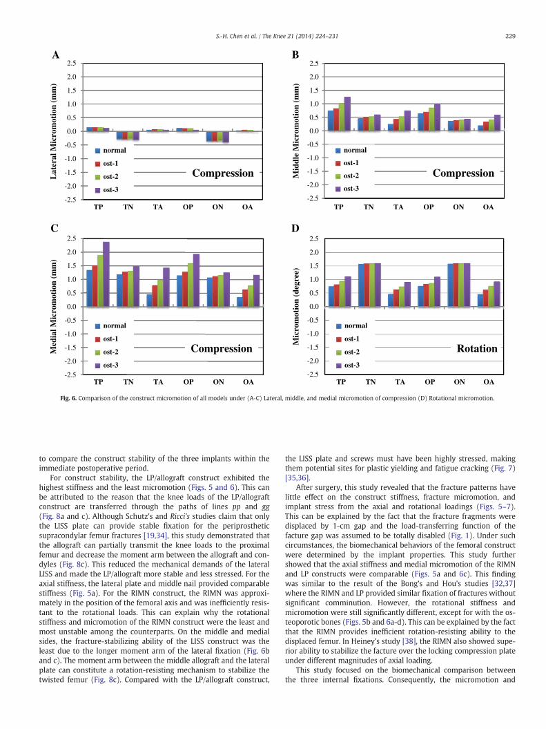
The axial and rotational stability was evaluated by the fracture micromotion, asshown in Fig. 6. The results of the axial and rotational micromotions were similar forthe transverse and oblique fractures. For the axial loading, the lateral gap of the TNconstruct was the most unstable and the micromotion of the TA construct was theleast unstable (Fig. 6a). For the middle micromotion, the TP construct provided theweakest support to the medial fracture and the micromotion of the TA construct wasthe highest, except for the ost-3 bone (Fig. 6b). Under normal and ost-2 conditions,the micromotion of the TP construct was respectively 80% and 152% higherthan those of the TN and TA constructs. For the medial micromotion, the TAconstruct provided the highest fracture-stabilizing ability in comparison to the othercounterparts (Fig. 6c). Under the normal and ost-2 conditions, the micromotion ofthe TA construct was respectively 58% and 44% less than those of the TN and TAconstructs. For the rotational loading, the micromotion of the TN construct wascomparable for all bone conditions and consistently higher than those of the TP and
Axi
al S
tiff
ness
(N
/mm
)R
otat
iona
l Sti
ffne
ss (
Nm
/Rad
)
0
50
100
150
200
250
300
350
400
450
500
550
600
TP TN TA
normal
ost-1
ost-2
ost-3
0
50
100
150
200
250
300
350
400
450
500
550
600
TP TN TA
normal
ost-1
ost-2
ost-3
A
B
Fig. 5. Comparison of the construct stiffness of all
TA constructs (Fig. 6d). For the normal and ost-2 bones, the rotational micromotionof the TN construct was respectively 1.91 and 2.83 times those of the TP and TAconstructs.
3.4. Implant stress
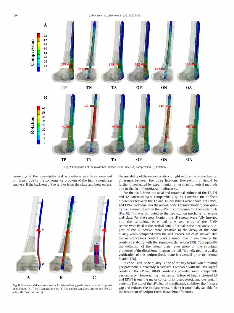
Fig. 7 shows the comparison of maximum von Mises stress among the implantsinstrumented into the ost-2 bone. For axial and rotational loading, the sequence ofthe implant stresses was similar among transverse and oblique fractures. For theaxial loading, the stress value of the TP construct was respectively 22% and 132% higherthan those of the TN and TA constructs (Fig. 7a). The maximum stresses of all implantsconsistently occurred around the fracture sites. For the rotational loading, the stress ofthe TN construct was 27% and 90% higher than those of the TP and TA construct,respectively. The TP and TA implants were highly stressed at the plate holes proximalto the fracture gap. The highest stress of the TN construct occurred at the secondproximal screw (Fig. 7a).
4. Discussion
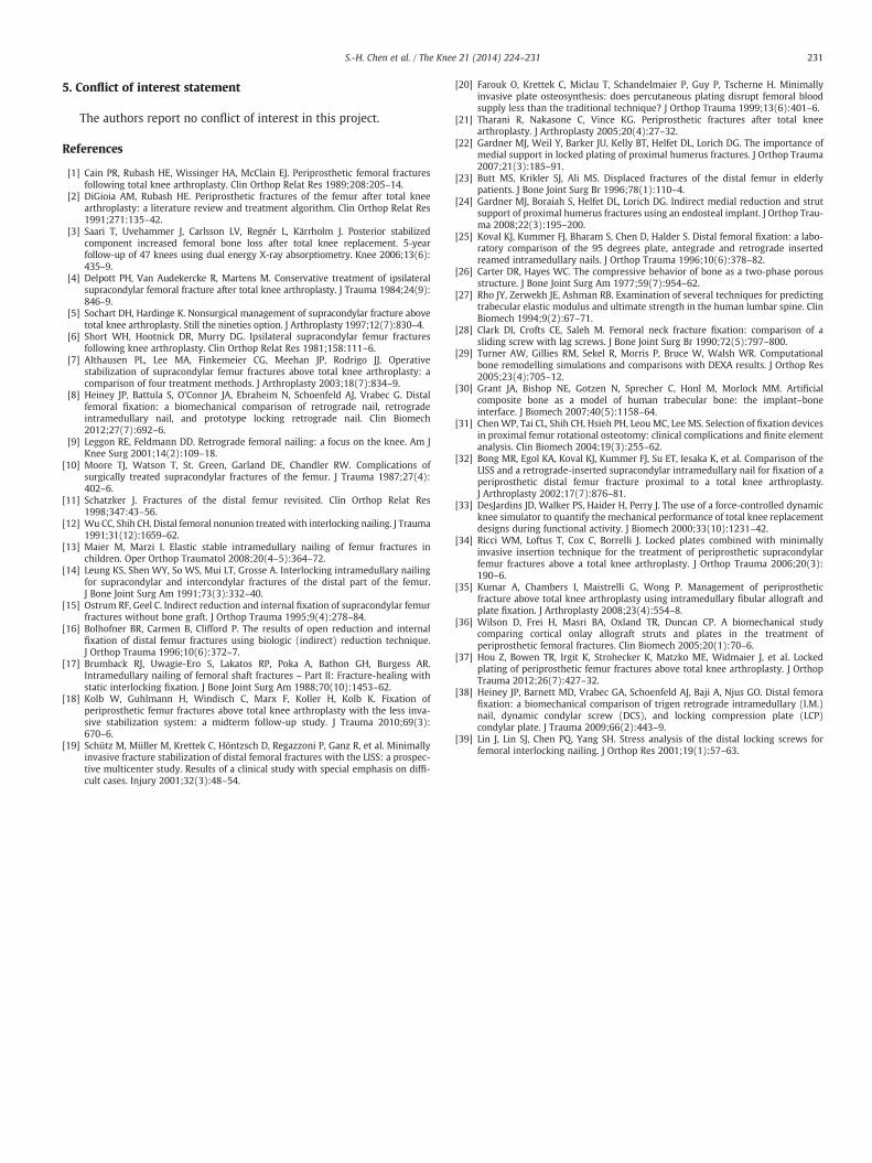
From the biomechanical viewpoint, the RIMN, LP, and LP/allograftwere the representatives of the middle, lateral, and middle/lateralsupport to the femur, respectively (Fig. 1). Fig. 8 schematicallyshows the load-transferring paths from the knee condyles to theproximal femur: through plate (line pp), nail (line nn), and allograft(line gg). The implant-induced support to the displaced femur wasevaluated in terms of construct stiffness, fracture micromotion, andimplant stress in this study. Without bony union, this study aimed
OP ON OA
Compression
OP ON OA
Rotation
models under (A) Compression. (B) Rotation.
A B
C D
-2.5
-2.0
-1.5
-1.0
-0.5
0.0
0.5
1.0
1.5
2.0
2.5
TP TN TA OP ON OA
Mic
rom
otio
n (d
egre
e)
Rotation
normal
ost-1
ost-2
ost-3
-2.5
-2.0
-1.5
-1.0
-0.5
0.0
0.5
1.0
1.5
2.0
2.5
TP TN TA OP ON OA
Lat
eral
Mic
rom
otio
n (m
m)
Compression
normal
ost-1
ost-2
ost-3-2.5
-2.0
-1.5
-1.0
-0.5
0.0
0.5
1.0
1.5
2.0
2.5
TP TN TA OP ON OA
Mid
dle
Mic
rom
otio
n (m
m)
Compression
normal
ost-1
ost-2
ost-3
-2.5
-2.0
-1.5
-1.0
-0.5
0.0
0.5
1.0
1.5
2.0
2.5
TP TN TA OP ON OA
Med
ial M
icro
mot
ion
(mm
)
Compression
normal
ost-1
ost-2
ost-3
Fig. 6. Comparison of the construct micromotion of all models under (A-C) Lateral, middle, and medial micromotion of compression (D) Rotational micromotion.
229S.-H. Chen et al. / The Knee 21 (2014) 224–231
to compare the construct stability of the three implants within theimmediate postoperative period.
For construct stability, the LP/allograft construct exhibited thehighest stiffness and the least micromotion (Figs. 5 and 6). This canbe attributed to the reason that the knee loads of the LP/allograftconstruct are transferred through the paths of lines pp and gg(Fig. 8a and c). Although Schutz's and Ricci's studies claim that onlythe LISS plate can provide stable fixation for the periprostheticsupracondylar femur fractures [19,34], this study demonstrated thatthe allograft can partially transmit the knee loads to the proximalfemur and decrease the moment arm between the allograft and con-dyles (Fig. 8c). This reduced the mechanical demands of the lateralLISS and made the LP/allograft more stable and less stressed. For theaxial stiffness, the lateral plate and middle nail provided comparablestiffness (Fig. 5a). For the RIMN construct, the RIMN was approxi-mately in the position of the femoral axis and was inefficiently resis-tant to the rotational loads. This can explain why the rotationalstiffness and micromotion of the RIMN construct were the least andmost unstable among the counterparts. On the middle and medialsides, the fracture-stabilizing ability of the LISS construct was theleast due to the longer moment arm of the lateral fixation (Fig. 6band c). The moment arm between the middle allograft and the lateralplate can constitute a rotation-resisting mechanism to stabilize thetwisted femur (Fig. 8c). Compared with the LP/allograft construct,
the LISS plate and screws must have been highly stressed, makingthem potential sites for plastic yielding and fatigue cracking (Fig. 7)[35,36].
After surgery, this study revealed that the fracture patterns havelittle effect on the construct stiffness, fracture micromotion, andimplant stress from the axial and rotational loadings (Figs. 5–7).This can be explained by the fact that the fracture fragments weredisplaced by 1-cm gap and the load-transferring function of thefacture gap was assumed to be totally disabled (Fig. 1). Under suchcircumstances, the biomechanical behaviors of the femoral constructwere determined by the implant properties. This study furthershowed that the axial stiffness and medial micromotion of the RIMNand LP constructs were comparable (Figs. 5a and 6c). This findingwas similar to the result of the Bong’s and Hou’s studies [32,37]where the RIMN and LP provided similar fixation of fractures withoutsignificant comminution. However, the rotational stiffness andmicromotion were still significantly different, except for with the os-teoporotic bones (Figs. 5b and 6a-d). This can be explained by the factthat the RIMN provides inefficient rotation-resisting ability to thedisplaced femur. In Heiney’s study [38], the RIMN also showed supe-rior ability to stabilize the facture over the locking compression plateunder different magnitudes of axial loading.
This study focused on the biomechanical comparison betweenthe three internal fixations. Consequently, the micromotion and
TN ONTP OPTA OA
128112
968064483216
0
337277
145 332192
152
A
Com
pres
sion
TN ONTP OPTA OA
6558433629221470
97
122
65 114
110
65
B
Rot
atio
n
Fig. 7. Comparison of the maximum implant stress under (A) Compression (B) Rotation.
230 S.-H. Chen et al. / The Knee 21 (2014) 224–231
loosening at the screw/plate and screw/bone interfaces were notsimulated due to the convergence problem of the highly nonlinearanalysis. If the back-out of the screws from the plate and bone occurs,
A B C
p
p
n
n
g
g
Fig. 8. Schematical diagrams showing load-transferring paths from the distal to proxi-mal femurs. (A) The LP contact, line pp. (B) The nailing construct, line nn. (C) The LP/allograft construct, line gg.
the instability of the entire construct might reduce the biomechanicaldifference between the three fixations. However, this should befurther investigated by experimental rather than numerical methodsdue to the fact of interfacial nonlinearity.
For the ost-3 bone, the axial and rotational stiffness of the TP, TN,and TA construct were comparable (Fig. 5). However, the stiffnessdifferences between the TA and TN constructs were about 93% (axial)and 139% (rotational) for the normal bone. Formicromotion, bone qual-ity had a minor effect on the RIMN in comparison to other constructs(Fig. 6). This was attributed to the two fixation mechanisms: screwsand plate. For the screw fixation, the LP screws were fully insertedinto the cancellous bone and only two ends of the RIMNscrews were fixed at the cortical bone. This makes the mechanical sup-port of the LP screws more sensitive to the decay of the bonequality when compared with the nail screws. Lin et al. showed thatthe nail-cancellous contact plays a minor role in maintaining theconstruct stability with the supracondylar region [39]. Consequently,the deflection of the lateral plate relies more on the structuralproperties of the distal femur than on the nail. This indicates that qualityverification of the periprosthetic bone is essential prior to internalfixation [28].
In conclusion, bone quality is one of the key factors when treatingperiprosthetic supracondylar factures. Compared with the LP/allograftconstruct, the LP and RIMN constructs provided more comparableperformance. However, the mechanical failure of highly stressed LPand RIMN is one the major concerns for osteoporotic and overweightpatients. The use of the LP/allograft significantly stabilizes the fracturegap and reduces the implant stress, making it potentially suitable forthe treatment of periprosthetic distal femur fractures.
231S.-H. Chen et al. / The Knee 21 (2014) 224–231
5. Conflict of interest statement
The authors report no conflict of interest in this project.
References
[1] Cain PR, Rubash HE, Wissinger HA, McClain EJ. Periprosthetic femoral fracturesfollowing total knee arthroplasty. Clin Orthop Relat Res 1989;208:205–14.
[2] DiGioia AM, Rubash HE. Periprosthetic fractures of the femur after total kneearthroplasty: a literature review and treatment algorithm. Clin Orthop Relat Res1991;271:135–42.
[3] Saari T, Uvehammer J, Carlsson LV, Regnér L, Kärrholm J. Posterior stabilizedcomponent increased femoral bone loss after total knee replacement. 5-yearfollow-up of 47 knees using dual energy X-ray absorptiometry. Knee 2006;13(6):435–9.
[4] Delpott PH, Van Audekercke R, Martens M. Conservative treatment of ipsilateralsupracondylar femoral fracture after total knee arthroplasty. J Trauma 1984;24(9):846–9.
[5] Sochart DH, Hardinge K. Nonsurgical management of supracondylar fracture abovetotal knee arthroplasty. Still the nineties option. J Arthroplasty 1997;12(7):830–4.
[6] Short WH, Hootnick DR, Murry DG. Ipsilateral supracondylar femur fracturesfollowing knee arthroplasty. Clin Orthop Relat Res 1981;158:111–6.
[7] Althausen PL, Lee MA, Finkemeier CG, Meehan JP, Rodrigo JJ. Operativestabilization of supracondylar femur fractures above total knee arthroplasty: acomparison of four treatment methods. J Arthroplasty 2003;18(7):834–9.
[8] Heiney JP, Battula S, O'Connor JA, Ebraheim N, Schoenfeld AJ, Vrabec G. Distalfemoral fixation: a biomechanical comparison of retrograde nail, retrogradeintramedullary nail, and prototype locking retrograde nail. Clin Biomech2012;27(7):692–6.
[9] Leggon RE, Feldmann DD. Retrograde femoral nailing: a focus on the knee. Am JKnee Surg 2001;14(2):109–18.
[10] Moore TJ, Watson T, St. Green, Garland DE, Chandler RW. Complications ofsurgically treated supracondylar fractures of the femur. J Trauma 1987;27(4):402–6.
[11] Schatzker J. Fractures of the distal femur revisited. Clin Orthop Relat Res1998;347:43–56.
[12] Wu CC, Shih CH. Distal femoral nonunion treatedwith interlocking nailing. J Trauma1991;31(12):1659–62.
[13] Maier M, Marzi I. Elastic stable intramedullary nailing of femur fractures inchildren. Oper Orthop Traumatol 2008;20(4–5):364–72.
[14] Leung KS, Shen WY, So WS, Mui LT, Grosse A. Interlocking intramedullary nailingfor supracondylar and intercondylar fractures of the distal part of the femur.J Bone Joint Surg Am 1991;73(3):332–40.
[15] Ostrum RF, Geel C. Indirect reduction and internal fixation of supracondylar femurfractures without bone graft. J Orthop Trauma 1995;9(4):278–84.
[16] Bolhofner BR, Carmen B, Clifford P. The results of open reduction and internalfixation of distal femur fractures using biologic (indirect) reduction technique.J Orthop Trauma 1996;10(6):372–7.
[17] Brumback RJ, Uwagie-Ero S, Lakatos RP, Poka A, Bathon GH, Burgess AR.Intramedullary nailing of femoral shaft fractures – Part II: Fracture-healing withstatic interlocking fixation. J Bone Joint Surg Am 1988;70(10):1453–62.
[18] Kolb W, Guhlmann H, Windisch C, Marx F, Koller H, Kolb K. Fixation ofperiprosthetic femur fractures above total knee arthroplasty with the less inva-sive stabilization system: a midterm follow-up study. J Trauma 2010;69(3):670–6.
[19] Schütz M, Müller M, Krettek C, Höntzsch D, Regazzoni P, Ganz R, et al. Minimallyinvasive fracture stabilization of distal femoral fractures with the LISS: a prospec-tive multicenter study. Results of a clinical study with special emphasis on diffi-cult cases. Injury 2001;32(3):48–54.
[20] Farouk O, Krettek C, Miclau T, Schandelmaier P, Guy P, Tscherne H. Minimallyinvasive plate osteosynthesis: does percutaneous plating disrupt femoral bloodsupply less than the traditional technique? J Orthop Trauma 1999;13(6):401–6.
[21] Tharani R, Nakasone C, Vince KG. Periprosthetic fractures after total kneearthroplasty. J Arthroplasty 2005;20(4):27–32.
[22] Gardner MJ, Weil Y, Barker JU, Kelly BT, Helfet DL, Lorich DG. The importance ofmedial support in locked plating of proximal humerus fractures. J Orthop Trauma2007;21(3):185–91.
[23] Butt MS, Krikler SJ, Ali MS. Displaced fractures of the distal femur in elderlypatients. J Bone Joint Surg Br 1996;78(1):110–4.
[24] Gardner MJ, Boraiah S, Helfet DL, Lorich DG. Indirect medial reduction and strutsupport of proximal humerus fractures using an endosteal implant. J Orthop Trau-ma 2008;22(3):195–200.
[25] Koval KJ, Kummer FJ, Bharam S, Chen D, Halder S. Distal femoral fixation: a labo-ratory comparison of the 95 degrees plate, antegrade and retrograde insertedreamed intramedullary nails. J Orthop Trauma 1996;10(6):378–82.
[26] Carter DR, Hayes WC. The compressive behavior of bone as a two-phase porousstructure. J Bone Joint Surg Am 1977;59(7):954–62.
[27] Rho JY, Zerwekh JE, Ashman RB. Examination of several techniques for predictingtrabecular elastic modulus and ultimate strength in the human lumbar spine. ClinBiomech 1994;9(2):67–71.
[28] Clark DI, Crofts CE, Saleh M. Femoral neck fracture fixation: comparison of asliding screw with lag screws. J Bone Joint Surg Br 1990;72(5):797–800.
[29] Turner AW, Gillies RM, Sekel R, Morris P, Bruce W, Walsh WR. Computationalbone remodelling simulations and comparisons with DEXA results. J Orthop Res2005;23(4):705–12.
[30] Grant JA, Bishop NE, Gotzen N, Sprecher C, Honl M, Morlock MM. Artificialcomposite bone as a model of human trabecular bone: the implant–boneinterface. J Biomech 2007;40(5):1158–64.
[31] ChenWP, Tai CL, Shih CH, Hsieh PH, Leou MC, Lee MS. Selection of fixation devicesin proximal femur rotational osteotomy: clinical complications and finite elementanalysis. Clin Biomech 2004;19(3):255–62.
[32] Bong MR, Egol KA, Koval KJ, Kummer FJ, Su ET, Iesaka K, et al. Comparison of theLISS and a retrograde-inserted supracondylar intramedullary nail for fixation of aperiprosthetic distal femur fracture proximal to a total knee arthroplasty.J Arthroplasty 2002;17(7):876–81.
[33] DesJardins JD, Walker PS, Haider H, Perry J. The use of a force-controlled dynamicknee simulator to quantify the mechanical performance of total knee replacementdesigns during functional activity. J Biomech 2000;33(10):1231–42.
[34] Ricci WM, Loftus T, Cox C, Borrelli J. Locked plates combined with minimallyinvasive insertion technique for the treatment of periprosthetic supracondylarfemur fractures above a total knee arthroplasty. J Orthop Trauma 2006;20(3):190–6.
[35] Kumar A, Chambers I, Maistrelli G, Wong P. Management of periprostheticfracture above total knee arthroplasty using intramedullary fibular allograft andplate fixation. J Arthroplasty 2008;23(4):554–8.
[36] Wilson D, Frei H, Masri BA, Oxland TR, Duncan CP. A biomechanical studycomparing cortical onlay allograft struts and plates in the treatment ofperiprosthetic femoral fractures. Clin Biomech 2005;20(1):70–6.
[37] Hou Z, Bowen TR, Irgit K, Strohecker K, Matzko ME, Widmaier J, et al. Lockedplating of periprosthetic femur fractures above total knee arthroplasty. J OrthopTrauma 2012;26(7):427–32.
[38] Heiney JP, Barnett MD, Vrabec GA, Schoenfeld AJ, Baji A, Njus GO. Distal femorafixation: a biomechanical comparison of trigen retrograde intramedullary (I.M.)nail, dynamic condylar screw (DCS), and locking compression plate (LCP)condylar plate. J Trauma 2009;66(2):443–9.
[39] Lin J, Lin SJ, Chen PQ, Yang SH. Stress analysis of the distal locking screws forfemoral interlocking nailing. J Orthop Res 2001;19(1):57–63.


![Meta-analysis of plate fixation versus intramedullary fixation ......intramedullary fixation (IF), the common devices in clinics are Knowles pinning [14,15], elastic stable intramedullary](https://img.pdfslide.net/doc/110x75/60ec8dbb516bc21c1e0f6489/meta-analysis-of-plate-fixation-versus-intramedullary-fixation-intramedullary.jpg)