Embed Size (px)
Citation preview
FINITE ELEMENT METHOD ANALYSIS OF MICROIRRIGATION
SYSTEM PRESSURE DISTRIBUTION
KANG Yaohu*and Soichi NISHIYAMA*
* Faculty of Agriculture,Kagawa University
Abstract It is very important to estimate corrective pressure distribution to analyse uniformity
of water application in microirrigation system.Finite element method is one of the very convenient
and accurate methods to do this analysis.If the nodal system is arranged and simplified reasonably,
personal computer can be used to calculate pressure distributioneven in a system with a large
number of water application devices, such as line source emitterand high density point source emit-
ters of trickle irrigation system.The accuracy of the solution is very high because theoretical cal-
culating procedure is used.The convergence is quick no need to think whether the initial estimates
of the nodal pressure are near or far from the final solution.
I. INTRODUCTION
As it has been expounded by many resea-
chers and engineers that estimation of correc-
tive pressure distribution is very important for
designing microirrigation system to apply uni-
form water to the irrigation field.Nowadays,
there are many methods,such as Hardy Cross
method(Described by Chenoweth and Crawfor-
d,1974,and Jeppson,1977),Newton-Raphson
method,the linear theoretical method (Wood
and Charles,1972),and the nonlinear theoretical
method by using iterative techniques (Solomon
and Keller,1974,Wu and Fangmeier,1974,and
Perold,1977).Every method has its own advan-
tages and disadvantages.For example,Hardy
Cross method can be used to get accurate
result but its convergence is slow due to the in-
dependent solution of loop and nodal equation.
The convergence of Newton-Raphson method is
quick if the initial estimated value is near tothe final solution but sometimes it has not ten-
dency to get the solution when initial estimate
is quite far off.The common disadvantages of
the above mentioned methods are concentrated
on the hydraulic analysis of a single lateral
line.
The finite element method is a systematic
numerical procedure for solving a complex
engineering problems and it was applied in the
analysis of drip irrigation submain unit Bralts
and Segerlind in 1985.The convergence of this
method is very quick since it considers the
boundary condition.It is also possible to calcu-
late the pressure variation directly as far as
the pressure at each emitter is known.This
method can be used as it is mentioned above,
however,it needs large computer memory due
to large matrix equation which is not conve-
nient for calculating with personal computer.
In this paper,some mathematical models will
be applied to analyse pressure distribution in
various microirrigation systems with finite ele-
ment method more efficiently and some
methods will be presented to reduce nodal num-
ber rationally to make that it is possible to use
finite element method analysing pressure distri-
bution in a microirrigation system with a large
number of water application devices such as
line source emitter and high density point
source emitter,etc..
II. THE MODELLING OF FINITE
ELEMENT METHOD
As it is shown in Fig.1,the finite element
*
香川大学農学部
キ ー ワ ー ド:Finit eelement method,Microirrigation,
Pressure distribution
農土 論集(169) 19
農業土木学会論文集第169号
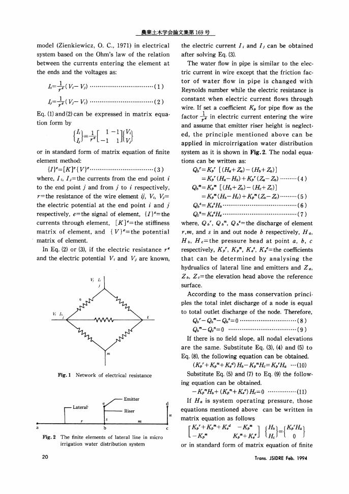
model(Zienkiewicz,0.C.,1971)in electrical
system based on the Ohm's law of the relation
between the currents entering the element at
the ends and the voltages as:
(1)
(2)
Eq.(1)and(2)can be expressed in matrix equa-
tion form by
or in standard form of matrix equation of finite
element method:
(3)
where,It,L=the currents from the end point i
to the end point j and from j to i respectively,
r=the resistance of the wire element ij,Vi,Vj=
the electric potential at the end point i and j
respectively,e=the signal of element,{I}e=the
currents through element,[K]e=the stiffness
matrix of element,and{V}e=the potential
matrix of element.
In Eq.(2)or(3),if the electric resistance re
and the electric potential Vi and Vj are known,
Fig.1 Network of electrical resistance
Fig.2 The finite elements of lateral line in micro
irrigation water distribution system
the electric current I and I;can be obtained
after solving Eq.(3).
The water flow in pipe is similar to the elec-
tric current in wire except that the friction fac-
tor of water flow in pipe is changed with
Reynolds number while the electric resistance is
constant when electric current flows through
wire.If set a coefficient Kp for pipe flow as the
factor 1/re in electric current entering the wire
and assume that emitter riser height is neglect-
ed,the principle mentioned above can be
applied in microirrigation water distribution
system as it is shown in Fig.2.The nodal equa-
tions can be written as:
(4)
(5)
(6)
(7)
where,Qbr,Qbm,Qbs=the discharge of element
r,m,and s in and out node b respectively,Ha,
Hb,Hc=the pressure head at point a,b,c
respectively,KPr,KeS,Kee the coefficients
that can be determined by analysing the
hydrualics of lateral line and emitters and Za,
Zb,Zc=the elevation head above the reference
surface.
According to the mass conservation princi-
ples the total inlet discharge of a node is equal
to total outlet discharge of the node.Therefore,
(8)
(9)
If there is no field slope,all nodal elevations
are the same.Substitute Eq.(3),(4)and(5)to
Eq.(8),the following equation can be obtained.
(10)
Substitute Eq.(5)and(7)to Eq.(9)the follow-
ing equation can be obtained.
(11)
If Ha is system operating pressure,those
equations mentioned above can be written in
matrix equation as follows
or in standard form of matrix equation of finite
20 Trans. JSIDRE Feb. 1994
FINITE ELEMENT METHOD ANALYSIS OF MICROIRRIGATION SYSTEM PRESSURE DISTRIBUTION
element method
(12)
where,[K]=the stiffness matrix of element,
{H}=the unknown pressure head matrix of ele-
ment and{F}=the known matrix of force.
III.HYDRAULICS OF LATERAL LINE
AND SUBMAIN
Emitters are pressure dissipating unit of mi-
croirrigation system.The relationship between
emitter discharge and operating pressure can
be described as follow
(13)
where,C=the coefficient of emitter discharge,
q=emitter discharge,H=the pressure head in
the lateral,and x=the exponent of H in emit-
ter discharge equation(x=1.0 for laminar emit-
ter,x=0.5 for orifice-type emitters,and x=0
for pressure compensating emitters*etc.).
Eq.(13)can be rearranged as
(14)
where
(15)
is a coefficient of emitter.
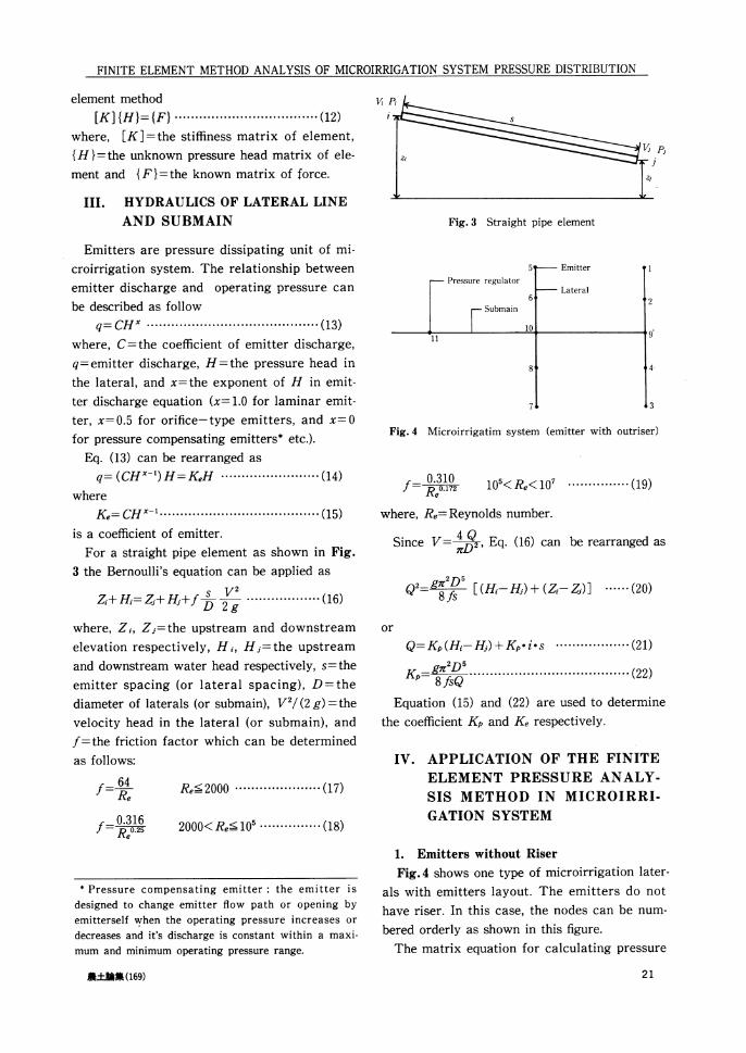
For a straight pipe element as shown in Fig.
3 the Bernoulli's equation can be applied as
(16)
where,Zi,Z;=the upstream and downstream
elevation respectively,Hi,Hj=the upstream
and downstream water head respectively,s=the
emitter spacing(or lateral spacing),D=the
diameter of laterals(or submain),V2/(2g)=the
velocity head in the lateral(or submain),and
f=the friction factor which can be determined
as follows:
(17)
(18)
Fig.3 Straight pipe element
Fig.4 Microirrigatim system (emitter with outriser)
(19)
where,Re=Reynolds number.
Since V=4Q/ƒÎD2,Eq.(16)can be rearranged as
(20)
or
(21)
(22)
Equation(15)and(22)are used to determine
the coefficient Kp and Ke respectively.
IV.APPLICATION OF THE FINITE
ELEMENT PRESSURE ANALY-
SIS METHOD IN MICROIRRI-
GATION SYSTEM
1.Emitters without Riser
Fig.4 shows one type of microirrigation later-
als with emitters layout.The emitters do not
have riser.In this case,the nodes can be num-
bered orderly as shown in this figure.
The matrix equation for calculating pressure
* Pressure compensating emitter:the emitter is
designed to change emitter flow path or opening by
emitterself when the operating pressure increases or
decreases and it's discharge is constant within a maxi-
mum and minimum operating pressure range.
農土論集(169) 21
農業土木学会論文集第169号
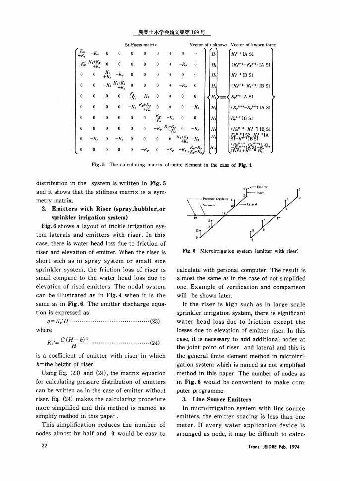
Fig.5 The calculating matrix of finite element in the case of Fig.4.
distribution in the system is written in Fig.5
and it shows that the stiffness matrix is a sym-
metry matrix.
2.Emitters with Riser(spray,bubbler,or
sprinkler irrigation system)
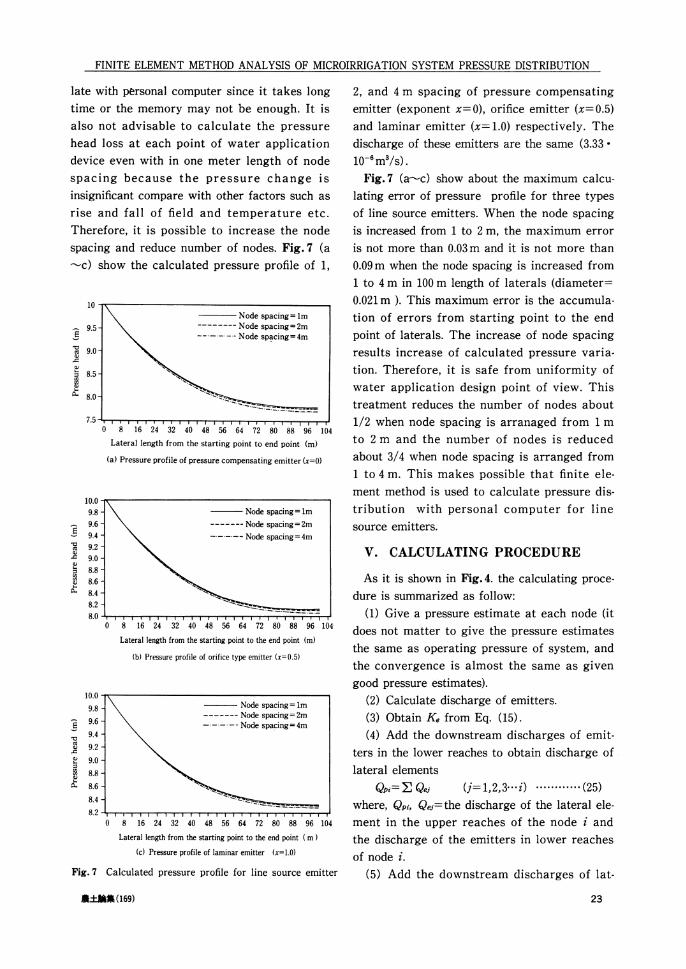
Fig.6 shows a layout of trickle irrigation sys-
tem laterals and emitters with riser.In this
case,there is water head loss due to friction of
riser and elevation of emitter.When the riser is
short such as in spray system or small size
sprinkler system,the friction loss of riser is
small compare to the water head loss due to
elevation of rised emitters.The nodal system
can be illustrated as in Fig.4 when it is the
same as in Fig.6.The emitter discharge equa-
tion is expressed as
(23)
where
(24)
is a coefficient of emitter with riser in which
h=the height of riser.
Using Eq.(23)and(24),the matrix equation
for calculating pressure distribution of emitters
can be written as in the case of emitter without
riser.Eq.(24)makes the calculating procedure
more simplified and this method is named as
simplify method in this paper.
This simplification reduces the number of
nodes almost by half and it would be easy to
Fig.6 Microirrigation system(emitter with riser)
calculate with personal computer.The result is
almost the same as in the case of not-simplified
one.Example of verification and comparison
will be shown later.
If the riser is high such as in large scale
sprinkler irrigation system,there is significant
water head loss due to friction except the
losses due to elevation of emitter riser.In this
case,it is necessary to add additional nodes at
the joint point of riser and lateral and this is
the general finite element method in microirri-
gation system which is named as not simplifiedmethod in this paper.The number of nodes as
in Fig.6 would be convenient to make com-
puter programme.
3.Line Source Emitters
In microirrigation system with line source
emitters,the emitter spacing is less than one
meter.If every water application device is
arranged as node,it may be difficult to calcu-
22 Trans.JSIDRE Feb.1994
FINITE ELEMENT METHOD ANALYSIS OF MICROIRRIGATION SYSTEM PRESSURE DISTRIBUTION
late with personal computer since it takes long
time or the memory may not be enough.It is
also not advisable to calculate the pressure
head loss at each point of water application
device even with in one meter length of node
spacing because the pressure change is
insignificant compare with other factors such as
rise and fall of field and temperature etc.
Therefore,it is possible to increase the node
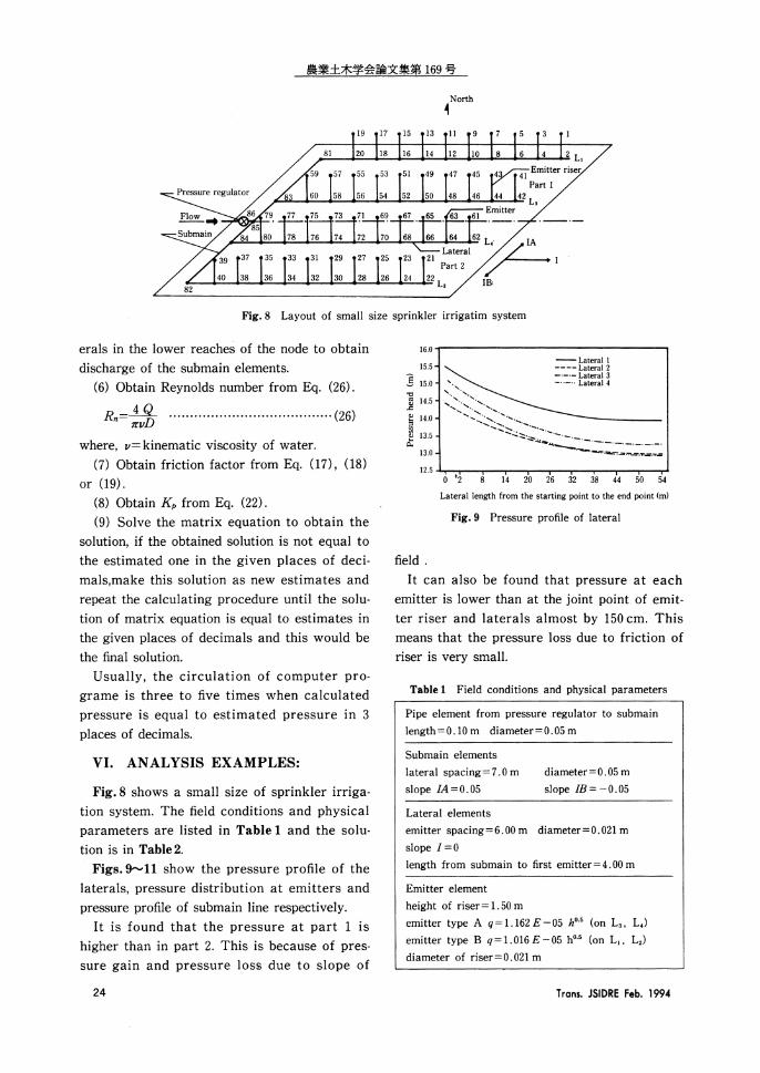
spacing and reduce number of nodes.Fig.7(a~c) showthecalculatedpressureprofileof1,
(a) Pressure profile of pressure compensating emitter(x=0)
(b) Pressure profile of orifice type emitter(x=0.5)
(c) Pressure profile of laminar emitter(x=1.0)
Fig.7 Calculated pressure profile for line source emitter
2,and 4 m spacing of pressure compensating
emitter (exponent x=0),orifice emitter(x=0.5)
and laminar emitter(x=1.0)respectively.The
discharge of these emitters are the same(3.33
10-6m3/s).
Fig.7 (a•`c)show about the maximum calcu-
lating error of pressure profile for three types
of line source emitters.When the node spacing
is increased from 1 to 2m,the maximum error
is not more than 0.03m and it is not more than
0.09m when the node spacing is increased from
1 to 4m in 100m length of laterals(diameter=
0.021m).This maximum error is the accumula-
tion of errors from starting point to the end
point of laterals.The increase of node spacing
results increase of calculated pressure varia-
tion.Therefore,it is safe from uniformity of
water application design point of view.This
treatment reduces the number of nodes about
1/2 when node spacing is arranaged from 1m
to 2 m and the number of nodes is reduced
about 3/4 when node spacing is arranged from
1 to 4m.This makes possible that finite ele-
ment method is used to calculate pressure dis-
tribution with personal computer for line
source emitters.
V.CALCULATING PROCEDURE
As it is shown in Fig.4. the calculating proce-
dure is summarized as follow:
(1) Give a pressure estimate at each node(itdoes not matter to give the pressure estimates
the same as operating pressure of system,and
the convergence is almost the same as given
good pressure estimates).(2) Calculate discharge of emitters.
(3) Obtain If Ke from Eq.(15).
(4) Add the downstream discharges of emit-
ters in the lower reaches to obtain discharge of
lateral elements
(25)
where,Qpi,Qej=the discharge of the lateral ele-
ment in the upper reaches of the node i and
the discharge of the emitters in lower reaches
of node i.
(5) Add the downstream discharges of lat-
農土論集(169) 23
農業土木学会論文集第169号
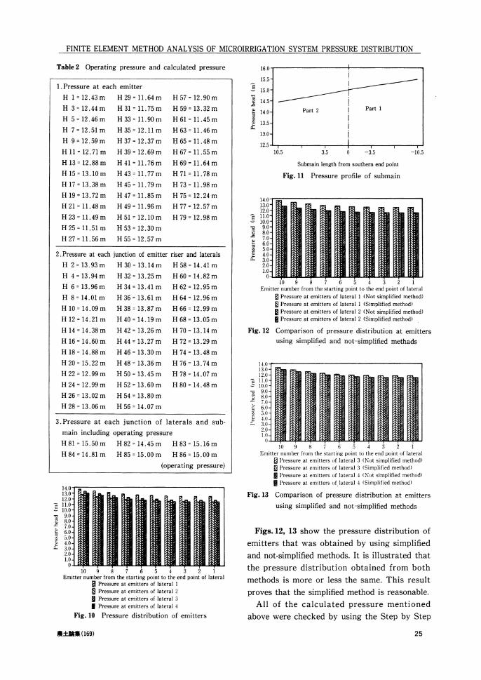
Fig.8 Layout of small size sprinkler irrigatim system
erals in the lower reaches of the node to obtain
discharge of the submain elements.
(6) Obtain Reynolds number from Eq.(26).
(26)
where,v=kinematic viscosity of water.
(7) Obtain friction factor from Eq.(17),(18)
or(19).
(8) Obtain Kp from Eq.(22).
(9) Solve the matrix equation to obtain the
solution,if the obtained solution is not equal to
the estimated one in the given places of deci-
mals,make this solution as new estimates and
repeat the calculating procedure until the solu-
tion of matrix equation is equal to estimates in
the given places of decimals and this would be
the final solution.
Usually,the circulation of computer pro-
grame is three to five times when calculated
pressure is equal to estimated pressure in 3
places of decimals.
VI.ANALYSIS EXAMPLES:
Fig.8 shows a small size of sprinkler irriga-
tion system.The field conditions and physical
parameters are listed in Table 1 and the solu-
tion is in Table 2.
Figs.9-11 show the pressure profile of the
laterals,pressure distribution at emitters and
pressure profile of submain line respectively.
It is found that the pressure at part 1 is
higher than in part 2.This is because of pres-
sure gain and pressure loss due to slope of
Fig.9 Pressure profile of lateral
field.
It can also be found that pressure at each
emitter is lower than at the joint point of emit-
ter riser and laterals almost by 150cm.This
means that the pressure loss due to friction of
riser is very small.
Table 1 Field conditions and physical parameters
24 Trans.JSIDRE Feb.1994
FINITE ELEMENT METHOD ANALYSIS OF MICROIRRIGATION SYSTEM PRESSUREDISTRIBUTION
Table 2 Operating pressure and calculated pressure
Fig.10 Pressure distribution of emitters
Fig.11 Pressure profile of submain
Fig.12 Comparison of pressure distribution at emitters
using simplified and not-simplified methads
Fig.13 Comparison of pressure distribution at emitters
using simplified and not-simplified methods
Figs.12,13 show the pressure distribution of
emitters that was obtained by using simplified
and not-simplified methods.It is illustrated that
the pressure distribution obtained from both
methods is more or less the same.This result
proves that the simplified method is reasonable.
All of the calculated pressure mentioned
above were checked by using the Step by Step
農土論集(169) 25
農業土木学会論文集第169号
method and it is found that results of the finite
element method are completely the same as the
results of the Step by Step method.
VII.CONCLUSION:
Finite element method can be used to analyse
pressure distribution in microirrigation system.
The advantages of this method includes to
obtain accurate pressure distribution at the
pressure controlled unit since the mathematical
procedure is theoretical.The uniformity of
water application can be determined directly
because the pressure of each emitter is
obtained.The convergence is quick and no
need to think about whether the initial esti-
mates of nodal pressure is near or far from the
final solution.It is possible to use in microir-
rigation system which has large number of
emitters such as line source emitters,etc.with
personal computer.
REFERENCES
1) Bralts, V. F. and Segerlind, Li.: Finite element
analysis of drip irrigation submain unit, Trans.
of ASAE, V. 28, pp.809•`814(1985)
2) Bralts and D. M. Edwards, Wu,I. P.: Drip irriga-
tion design and evaluation based on the statisti-
cal uniformity concept, Advances in Irrigation,
Vol.4, Academic Press Inc., pp.67•`117(1987)
3) Bernuth, R. D. and Tonya Wilson: Friction fac-
tors for small diameter plastic pipes, Journal of
Hydraulic Engineering, ASCE, Vol.115, No.2, pp.
183•`192(1989)
4) Fu, L., Dong, W. C. and Zheng, Y. Q. etc.: Techni-
cal guidance for microirrigation engineering, Pub-lished by Electric Power and Water Conservancy
Press, China, (1987)5) Kamand, F. Z.: Hydraulic friction factors for
pipe flow, Journal of Irrigation and Drainage
Engineering, ASCE, Vol.114, No.2, pp.311•`323
(1988)
6) Kell, J. and Blieser, R. D.: Sprinkler and trickleirrigation, Published by Van Nostrand Reinhold,
New York(1990)7) Nakayama, F. S. and Bucks, D. A.: Trickle irri-
gation for crop production, Elsevier Science Pub-lication B. V. (1986)
8) Warrick, A. W. and Yitayew M.: Trickle lateral
hydraulics I: Analytical Solution, Journal of Irri-
gation and drainage Engineering, ASCE, Vol.114,
No.2, pp.281•`288(1988)
9) Wu, I. P., Saruwatari C. A. and Gitlin, H. M.:
Design of drip irrigation lateral length on uni-
form slope, Irrig. Sci. 4, pp.11.7•`135(1983)
10) Zienkiewicz, O. C.: The finite element Method in
engineering Science, Published by McGraw HillPublication Company Limited, London(1971)
〔1993.3.11.受 稿 〕
〔この研 究論文 に対 す る公 開の質疑 あ るいは討議(4,000
字以内,農 業 土木学会論文集編集委 員会 あて)は,1994
年8月24日 まで受付 け ます。〕
26 Tran5.JSIDRE Feb.1994
農業土木学会論文集 第169号 内容紹介
〔研究論文〕変動する降雨入力のもとでの降雨浸透現象
- 降雨浸透現象の研究(II)-
富永雅樹変動する降雨強度が浸透現象に与 える影響 を考察す る
ために実験 を行 った。 まず,総 降雨量が同 じで,降 雨強
度 と継続時間が異 なる降雨入力下 での長 さ5mの カ ラ
ム実験か らは,継 続時間が長 ければ,短 時間の豪雨の と
きよ り,降 雨終了時の浸潤前線が地盤中の深部 に到達す
る現象が観察 された。 つぎに,一 定 の休止期 間を置 いて
くりか えす方形波状 の降雨入力下 での実験では,2mの
関東 ローム土地盤では方形波状 の降雨入力に対応 した地
下水流出があること等 を観測 した。 これ らの現 象か ら,
動的平衡浸透状態での水分量は降雨入力の強度 の影響 を
受 けていること,お よび初期土壌水分量の分布 が降雨浸
透 に与 える効果等について考察 した。
(農 土論 集169,pp.1~10)キー ワー ド 降雨浸透,浸 潤前線,動 水含水率,毛 管懸垂水,開 放不
飽和毛管浸透,動 的平衡浸透,毛 管水縁
〔研究論 文〕
FINITE ELEMENT METHOD ANALYSIS OFMICROIRRIGATION SYSTEM PRESSURE
DISTRIBUTION(本 文=英 文)
康 躍 虎 ・西 山壮一
潅水施設の設計の目的 は均等散水 にあ ると言っても過
言ではない。吐出流量が水頭の関数であ るため,均 等散
水の検討 に対 して,水 頭分布を求 める必要が生 じる。本
論文では,ラ テラル管 と給水管 とを一体 として,有 限要
素法によ り水理解析 を行い,そ の解析の有効性 を論 じた。
また,ド リップ潅概 システムを効率的に解析 する手法
を論 じた。
(農 土 論 集169,pp.19~26)
キー ワー ド 有限要素法,マ イクロ潅概,圧 力分布
〔研究論文〕水撃モデルによるパイプライン非定常流(高周波,低 周波)および定常流の統一的な
数値解析法- 混合型時間補間特性法と最適計算格子形成法-
島田正志
大規模パ イプラインの非定常流(高 周波,低 周波)お よび定常流を水撃モデル で統一的に効率的に解析 しうる混
合型時間補間特性法 を提案 した。本法で は,補 間 による
数値振幅減衰,分 散 の評価に より適切な時間ステップを決 め,最 適 な格子形成 を行 う。特 に,短 い管路が ある場
合 には,陰的時間補 間により,飛躍的 に大 きな時間 ステップを使用できる。パ イプライ ンモデル に対する数値計算
の結果か ら,混 合型時間補間特性法の有効性 を検証 したが,低 周波流れ解析 でも,圧 力振動 を再現 し,弁 遮断問
題 も容易に扱 えるな ど,剛 性 モデル解析にない長所があ
る。
(農 土 論 集169,pp.35~45)キー ワー ド パイプライン,水 撃解析,特 性直線法,陰 解法,陽 解法,
低周波,定 常流,安 定性解析,格 子形成
〔研究論文〕先行降雨のもとでの降雨浸透現象
- 降雨浸透現象の研究(III)-
富永雅樹
先行降雨があった場合の降雨浸透現象を明 らか にする
ために実験 と考察 を行った。深さ5mの 円柱状の模擬地
盤 に,30mm/h×2hの 降雨入力 を毎 日同 じ時刻か ら5
日間与 える実験 を行 った結果 では,2日 目以降の降雨入
力 によって,す でに降下の途 中にある1次 的な浸潤前線
の上部の浸透帯 に2次 的な浸潤前線が出現 した。2次 的
な浸潤前 線 は土壌水 分の増加 につれ降下速 度が速 くな
り,1次 的な浸潤前線の中に吸収 され,そ の降下運動を
継続 させ ることなどがわかった。 これ らの現象 は,先 行
降雨が開放不飽和毛管浸透 モデル にお ける毛管懸垂水を
発達 させ ると考 える ことによ り説明で きる ことを示 し
た。
(農 土論 集169,pp.11~18)
キ ー ワー ド 降雨浸透,浸 潤前線,毛 管懸垂水,土 壌水分量分布,開
放不飽和毛管浸透,先 行降雨,毛 管水縁
〔研究論文〕高炉セメン トを用いた暑中コンクリー トの
凝結時間ならびに圧縮強度特性
月岡 存
高温(30~33゜C)条 件 下において,高 炉 セメン ト中の
高炉ス ラグ微粉末の含有量 と使用混和剤の種類(標 準形
と遅延形)が,コ ンクリー トの凝結時間,お よび養生条
件 と材令の異 なるコンクリー トの圧縮強度 に及ぼす影響
について,実 験的 に検討 した。
その結果,(1)高 炉セメ ン トの使用 は普通 ボル トランド
セメン トより,ま た,遅 延形 の混和剤の使用 は,コ ンク
リー トの凝結時間の遅延 に効果が ある。(2)高炉セ メン ト
コンクリー トは使用混和 剤の種類 にかかわ らず,長 期材
令 にお ける強度増進が大である。(3)高温乾燥 の下では,
コンクリー トの材料や種類 よ りも脱型材令 が圧縮強度に
大 き く影響 する,こ とな どを明 らか にした。
(農 土論 集169,pp.27~33)
キ ー ワー ド 高炉セメン ト,暑 中 コンクリー ト,コ ンクリー トの凝結
時間,圧 縮強度,高 温養生
〔研究報文 〕
釧 路 東 地 区 に お け る地 盤 改 良 工 事
千葉 佳彦 ・金 山慎 一 ・上 野 賢治 ・日下部 史明
広域農道釧路東地区は北海道東部,釧 路支庁管内のほ
ぼ中央部に位置す る。 この うち,第 一期工事 区間 は,軟
弱地盤である釧路湿原内を通過す る。広里大橋部 は,す
べ り破壊,残 留沈下,橋 台の側方流動,導 水 カルバー ト
の変形な どが予測 された。 これ らの対策 として,地 盤 改
良 を行 うこととし,橋 台背面部 には深層混合処理工法,
道路部には砕石 コンパ クシ ョンパイル工法 を施工 した。
これ らの工事概要 を示す とともに,各 工法 の設計法,
施工手順,施 工管理方法な どについて報告 する。
(農 土論 集169,pp.47~55)キ ー ワー ド 地盤改良,砕 石コンパクションパイル工法,深 層混合処
理工法,広 域農道,農 業経営の安定