Embed Size (px)
Citation preview
Journal of Biomechanics ∎ (∎∎∎∎) ∎∎∎–∎∎∎
Contents lists available at SciVerse ScienceDirect
journal homepage: www.elsevier.com/locate/jbiomech
Journal of Biomechanics
0021-92http://d
n CorrE-m
dandrew
Pleaswith
www.JBiomech.com
Review
Finite element modeling mesh quality, energy balance and validationmethods: A review with recommendations associatedwith the modeling of bone tissue
Timothy A. Burkhart a,n, David M. Andrews b, Cynthia E. Dunning a
a Jack McBain Biomechanical Testing Laboratory, Department of Mechanical and Materials Engineering, Western University, 1151 Richmond Street, London,ON, Canada N6A 5B9b Department of Kinesiology, University of Windsor, Windsor, ON, Canada N9B 3P4
a r t i c l e i n f o
Article history:
Accepted 16 March 2013The use of finite element models as research tools in biomechanics and orthopedics has grown exponentiallyover the last 20 years. However, the attention to mesh quality, model validation and appropriate energy
Keywords:Validation metricMesh qualityEnergyFinite element modeling
90/$ - see front matter & 2013 Elsevier Ltd. Ax.doi.org/10.1016/j.jbiomech.2013.03.022
esponding author. Tel.: +1 519 661 2111.ail addresses: [email protected] (T.A. [email protected] (D.M. Andrews), cdunning@u
e cite this article as: Burkhart, T.A., erecommendations associated with t
a b s t r a c t
balance methods and the reporting of these metrics has not kept pace with the general use of finite elementmodeling. Therefore, the purpose of this review was to summarize the current state of finite elementmodeling validation practices from the literature in biomechanics and orthopedics and to present specificmethods and criteria limits that can be used as guidelines to assess mesh quality, validate simulation resultsand address energy balance issues.
Of the finite element models reviewed from the literature, approximately 42% of them were notadequately validated, while 95% and 98% of the models did not assess the quality of the mesh or energybalance, respectively. A review of the methods that can be used to assess the quality of a mesh (e.g., aspectratios, angle idealization and element Jacobians), measure the balance of energies (e.g., hour glass energy andmass scaling), and quantify the accuracy of the simulations (e.g., validation metrics, corridors, statisticaltechniques) are presented.
& 2013 Elsevier Ltd. All rights reserved.
Contents
1. Introduction . . . . . . . . . . . . . . . . . . . . . . . . . . . . . . . . . . . . . . . . . . . . . . . . . . . . . . . . . . . . . . . . . . . . . . . . . . . . . . . . . . . . . . . . . . . . . . . . . . . . . . . . . . 12. Review of the literature. . . . . . . . . . . . . . . . . . . . . . . . . . . . . . . . . . . . . . . . . . . . . . . . . . . . . . . . . . . . . . . . . . . . . . . . . . . . . . . . . . . . . . . . . . . . . . . . . 2
2.1. Methods . . . . . . . . . . . . . . . . . . . . . . . . . . . . . . . . . . . . . . . . . . . . . . . . . . . . . . . . . . . . . . . . . . . . . . . . . . . . . . . . . . . . . . . . . . . . . . . . . . . . . . . 22.2. Results . . . . . . . . . . . . . . . . . . . . . . . . . . . . . . . . . . . . . . . . . . . . . . . . . . . . . . . . . . . . . . . . . . . . . . . . . . . . . . . . . . . . . . . . . . . . . . . . . . . . . . . . 2
3. Mesh quality assessment. . . . . . . . . . . . . . . . . . . . . . . . . . . . . . . . . . . . . . . . . . . . . . . . . . . . . . . . . . . . . . . . . . . . . . . . . . . . . . . . . . . . . . . . . . . . . . . . 33.1. Mesh shape . . . . . . . . . . . . . . . . . . . . . . . . . . . . . . . . . . . . . . . . . . . . . . . . . . . . . . . . . . . . . . . . . . . . . . . . . . . . . . . . . . . . . . . . . . . . . . . . . . . . 53.2. Aspect ratios . . . . . . . . . . . . . . . . . . . . . . . . . . . . . . . . . . . . . . . . . . . . . . . . . . . . . . . . . . . . . . . . . . . . . . . . . . . . . . . . . . . . . . . . . . . . . . . . . . . 53.3. Angle idealization . . . . . . . . . . . . . . . . . . . . . . . . . . . . . . . . . . . . . . . . . . . . . . . . . . . . . . . . . . . . . . . . . . . . . . . . . . . . . . . . . . . . . . . . . . . . . . . 53.4. Element Jacobians . . . . . . . . . . . . . . . . . . . . . . . . . . . . . . . . . . . . . . . . . . . . . . . . . . . . . . . . . . . . . . . . . . . . . . . . . . . . . . . . . . . . . . . . . . . . . . . 6
4. Model validation and energy assessment. . . . . . . . . . . . . . . . . . . . . . . . . . . . . . . . . . . . . . . . . . . . . . . . . . . . . . . . . . . . . . . . . . . . . . . . . . . . . . . . . . . 64.1. Energy balance. . . . . . . . . . . . . . . . . . . . . . . . . . . . . . . . . . . . . . . . . . . . . . . . . . . . . . . . . . . . . . . . . . . . . . . . . . . . . . . . . . . . . . . . . . . . . . . . . . 64.2. Model/experimental comparison . . . . . . . . . . . . . . . . . . . . . . . . . . . . . . . . . . . . . . . . . . . . . . . . . . . . . . . . . . . . . . . . . . . . . . . . . . . . . . . . . . . 7
5. Summary . . . . . . . . . . . . . . . . . . . . . . . . . . . . . . . . . . . . . . . . . . . . . . . . . . . . . . . . . . . . . . . . . . . . . . . . . . . . . . . . . . . . . . . . . . . . . . . . . . . . . . . . . . . . 9Conflict of interest statement . . . . . . . . . . . . . . . . . . . . . . . . . . . . . . . . . . . . . . . . . . . . . . . . . . . . . . . . . . . . . . . . . . . . . . . . . . . . . . . . . . . . . . . . . . . . . . . . 9Acknowledgments . . . . . . . . . . . . . . . . . . . . . . . . . . . . . . . . . . . . . . . . . . . . . . . . . . . . . . . . . . . . . . . . . . . . . . . . . . . . . . . . . . . . . . . . . . . . . . . . . . . . . . . . . 9References . . . . . . . . . . . . . . . . . . . . . . . . . . . . . . . . . . . . . . . . . . . . . . . . . . . . . . . . . . . . . . . . . . . . . . . . . . . . . . . . . . . . . . . . . . . . . . . . . . . . . . . . . . . . . . . 9
ll rights reserved.
),wo.ca (C.E. Dunning).
t al., Finite element modeling mesh quality, energy balance and validation methods: A reviewhe.... Journal of Biomechanics (2013), http://dx.doi.org/10.1016/j.jbiomech.2013.03.022i
T.A. Burkhart et al. / Journal of Biomechanics ∎ (∎∎∎∎) ∎∎∎–∎∎∎2
1. Introduction
Experimental testing on human participants and cadavericspecimens provides researchers in biomechanics and orthopedicswith valuable insights into how the bones of the human bodyrespond to loading and why they might become injured as a resultof different loading scenarios. However, in many instances, experi-mental testing on humans and cadavers is not always feasible. Forexample, to ensure the safety of participants, in vivo testing mustbe limited to sub-maximal loads and non-invasive testing techni-ques. Furthermore, failure tests on cadaveric specimens are inher-ently destructive and can become costly (Rogge et al., 2002). Incomparison, finite element models provide a feasible alternativefor predicting the response of bone under a variety of loadingconditions and have become a popular and powerful tool amongbiomechanics and orthopedics researchers over the last 20 to 30years (Anderson et al., 2007; Erdemir et al., 2012). As reported byErdemir et al. (2012), there has been a 6000% increase in thenumber of finite element modeling papers published between theyears 1980 and 2009. However, the attention to mesh quality,model validation and appropriate energy balance methods duringthis period has not adequately kept pace with the general use offinite element modeling approaches. This is particularly true in theorthopedics and biomechanics literature, where the use of thesemetrics lags behind that found in the mainstream materialsengineering journals (Lund et al., 2012).
Recently, a number of papers that address the issues of modelverification, validation (Anderson et al., 2007; Cristofolini et al.,2010; Henninger et al., 2010; Lund et al., 2012) and presentation ofmodeling results (Erdemir et al., 2012) have been published andprovide the reader with an excellent perspective regarding theseissues. While these papers present essential definitions and gen-eral modeling guidelines, they stop short of recommendingspecific validation procedures. Rather, they focus only on thevalidation of simulation results, and do not address the areas ofmesh quality and energy balance assessments. As the primaryfocus of biomechanics and orthopedics finite element models isgenerally some aspect of human health (e.g., implant failure, injuryrisk assessment, fracture fixation efficacy), it is imperative that themodel represent the physical system with as much accuracy aspossible. Therefore, sources of error (mesh quality, energy balance,simulation accuracy) must be considered, quantified and mini-mized to prevent erroneous findings. Furthermore, the standardi-zation of model assessment criteria would allow for bettercomparison of models between research groups.
Therefore, the purpose of this paper is threefold: (i) to conducta literature review to highlight the current state of finite elementmodeling validation practices in orthopedics and biomechanics;(ii) to present specific methods that should be used to assess meshquality, validate simulation results and address energy balanceissues; and (iii) to recommend criteria limits to be used inassessing the accuracy of a finite element model. While thefindings of the literature review and the associated recommenda-tions are applicable to most biomechanical and orthopedic finiteelement models, the focus of this work is on models representingbone tissue.
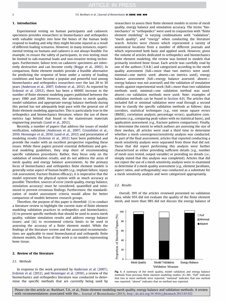
Fig. 1. A summary of the mesh quality, model validation and energy balancemethods from previous finite element modeling studies (N¼80). “Full” indicatesthat two or more methods were reported; “minimal” indicates that one methodwas reported; “absent” indicates that no method was reported.
2. Review of the literature
2.1. Methods
In response to the work presented by Anderson et al. (2007),Erdemir et al. (2012), and Henninger et al. (2010), a review of thebiomechanics and orthopedics literature was conducted to deter-mine the specific methods that are currently being used by
Please cite this article as: Burkhart, T.A., et al., Finite element modelinwith recommendations associated with the.... Journal of Biomechanic
researchers to assess their finite element models in terms of meshquality, energy balance and simulation accuracy. The terms “bio-mechanics” or “orthopedics” were used in conjunction with “finiteelement modeling” in varying combinations with “validation”,“mesh quality”, and “energy” when conducting the literaturesearch. Articles were chosen which represented a variety ofanatomical locations from a number of different journals andwhich represented both basic and applied work. However, giventhe volume of articles dedicated to orthopedics and biomechanicsfinite element modeling, the review was limited to models thatprimarily involved bone tissue. Each article was carefully read byone of the authors (T.A.B.) and categorized according to the meshquality assessment (full¼more than two metrics were used;minimal¼one metric used; absent¼no metrics used), energybalance assessment (full¼energy balance assessed; absent¼energy balance was not assessed) and the validation of simulationresults against experimental work (full¼more than two validationmethods used; minimal¼one validation method was used;absent¼no validation methods were used; Note: examples ofvalidation methods can be found in Section 4.0). The articles thatincluded full or minimal validation were read through a secondtime to classify the specific validation methods as follows: datacorridors, statistical techniques (e.g., root mean square errors(RMSE), correlation analysis, percentage errors), qualitative com-parisons (e.g., comparing peak values with no statistical basis), andapplication assessment (e.g., fracture pattern comparison). Finally,to determine the extent to which authors are assessing the size oftheir meshes, all articles were read a third time to determinewhether a mesh convergence/sensitivity analysis was conducted.As part of the final assessment, articles that reported conducting amesh sensitivity analysis were separated from those that did not.Those that did report performing this analysis were furthercharacterized as either providing sufficient details (e.g., numberof mesh sizes tested, output variable) or providing no details (i.e.,simply stated that this analysis was completed). Articles that didnot report the use of a mesh sensitivity analysis were re-examinedto determine if a mesh quality assessment (e.g., element Jacobians,aspect ratios, and orthogonality) was conducted as a substitute fora mesh sensitivity analysis and were categorized appropriately.
2.2. Results
Overall, 39% of the articles reviewed presented no validationdata, while 95% did not evaluate the quality of the finite elementmesh, and more than 98% did not discuss the energy balance of
g mesh quality, energy balance and validation methods: A reviews (2013), http://dx.doi.org/10.1016/j.jbiomech.2013.03.022i

T.A. Burkhart et al. / Journal of Biomechanics ∎ (∎∎∎∎) ∎∎∎–∎∎∎ 3
the model (Fig. 1 and Table 1) despite 43% of the reviewed paperspresenting dynamic simulation results. Of the papers that includedany type of validation procedure, 47% included only a qualitativeassessment and 57% validated their model with respect to speci-men-specific, original experimental data (i.e., 43% made compar-isons to previously reported data in the literature) (Table 1).
Finally, only 33% of all the articles reviewed chose the size oftheir mesh based on the results of a mesh sensitivity analysis, andof these, only 57% included the details of their analysis (Fig. 2).Of the 67% that did not report performing a mesh sensitivityanalysis, almost 90% also did not include any type of mesh qualityassessment (Fig. 2).
3. Mesh quality assessment
The accuracy and efficiency of finite element simulations(i.e., the solution to the partial differential equations) is highlypredisposed to the quality of the finite element mesh (Knupp,2007). Knupp (2007), defines the elusive term “mesh quality” as“the characteristics of a mesh that permit a particular numerical
Table 1Summary of the mesh quality, energy balance and model validation methods reported
Author (year) Anatomicallocation
Mesh qualityassessment
Gatti et al. (2010) Glenoid NoMoore et al. (2010) Glenoid NoHopkins et al. (2006) Glenoid NoDebski et al. (2005) Glenoid NoGupta et al. (2004) Glenoid NoBuchler et al. (2002) Glenoid NoMerz et al. (1997) Elbow NoClavert et al. (2006) Humerus NoChennimalai Kumar et al. (2010) Rat Ulna NoKotha et al. (2004) Rat Ulna NoLu et al. (2012) Mouse Forearm NoTaylor et al. (2003) Turkey Ulna NoChamoret et al. (2011) Hand NoGislason et al. (2009) Wrist YesGuo et al. (2009) Wrist NoLedoux et al. (2001) Wrist NoAnderson et al. (2008) Radius NoBoutroy et al. (2008) Radius NoBuchanan and Ural (2010) Radius NoCarrigan et al. (2003) Radius NoEdwards and Troy (2012) Radius NoMacneil and Boyd (2008) Radius NoPistoia et al. (2002) Radius NoPistoia et al. (2003) Radius NoRogge et al. (2002) Radius NoTroy and Grabiner (2007) Radius NoUlrich et al. (1999) Radius NoZhong et al. (2009) Spine NoClausen et al. (1997) Spine NoTadepalli et al. (2011) Spine NoMacNeil et al. (2012) Spine NoHussain et al. (2010) Spine NoTang and Meng (2011) Spine NoChosa et al. (2004) Spine NoSkalli et al. (1993) Spine NoWomack et al. (2011) Spine NoGalbusera et al. (2011) Spine NoMassey et al. (2012) Spine NoGuo et al. (2011) Spine NoPanzer et al. (2011) Spine NoNoailly et al. (2012) Spine NoSchmidt et al. (2007) Spine NoTang and Rebholz (2011) Spine NoEichenseer et al. (2011) Spine NoOzan et al. (2010) Femur NoYosibash et al. (2010) Femur NoAnderson et al. (2008) Femur No
Please cite this article as: Burkhart, T.A., et al., Finite element modelinwith recommendations associated with the.... Journal of Biomechanic
partial differential equation simulation to be efficiently performedwith fidelity to the underlying physics and with the accuracyrequired for the problem” (p. 2). Given the complex geometryassociated with human bones, elements with large distortions canoccur and are potential sources of low accuracy or solutioninstability (Valle and Ray, 2005). Two primary issues arise whenconsidering the quality of a finite element mesh. The first is theshape of the elements that are chosen to discretize the geometry.When generating a mesh for biological structures, especially bone,there are generally two element shapes that are used: tetrahedraland hexahedral (four node and eight node versions, respectively).In general, hexahedral elements are considered to be moreaccurate and efficient than their tetrahedral counterparts espe-cially when performing dynamic simulations. Also a considerationis the coarseness of the mesh—in other words, the number ofelements from which the mesh is composed. It is generally agreedupon in the literature that an optimal mesh density exists thatprovides the most accurate solution with the smallest possiblenumber of elements, as commonly determined through the use ofa sensitivity analysis. However, as reported previously, this type ofanalysis is not as common as is perceived, and when it is
in the studies reviewed from the literature.
Modelvalidation
Comparison toexperimental
Energybalance
Type of simulation
Yesa Yes Yes Quasi-StaticYesb Yes No Quasi-StaticYesc Yes No DynamicNo No StaticYesb Yes No StaticNo No StaticNo No StaticNo No StaticYesa No No Quasi-StaticNo No DynamicYes Yes No StaticYesc No No DynamicNo No DynamicNo No StaticYesc No No StaticNo No StaticYesc,d No No StaticNo No StaticNo No StaticNo No StaticYesb Yes Yes Quasi-StaticYesb Yes No StaticYesb Yes No StaticYesb Yes No StaticYesb Yes No StaticNo No DynamicNo No StaticYesc Yes No StaticYesc No No StaticNo No StaticYesb No No StaticYesc No No DynamicYesc No No StaticYesc No No StaticYesc No No StaticYesa Yes No DynamicNo No StaticNo No DynamicNo No N/AYesc No No DynamicNo No DynamicYesc No No DynamicYesc No No DynamicYesc No No StaticYesb Yes No StaticNo No StaticYesc,d Yes No Dynamic
g mesh quality, energy balance and validation methods: A reviews (2013), http://dx.doi.org/10.1016/j.jbiomech.2013.03.022i
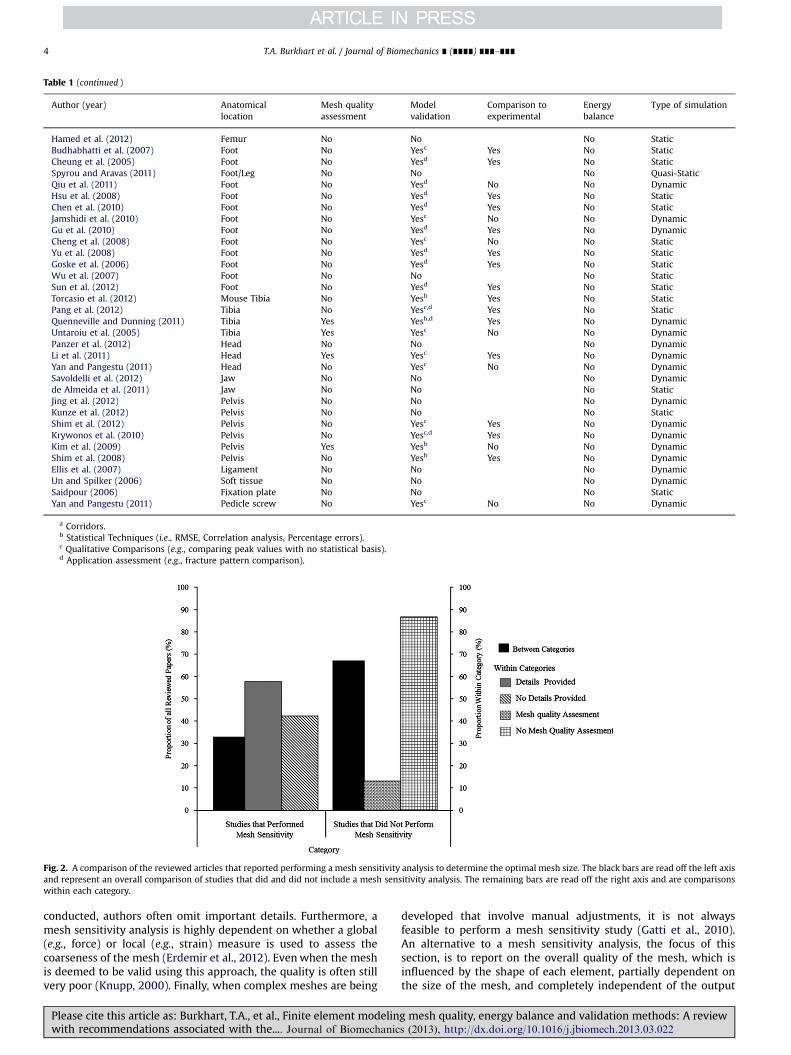
Table 1 (continued )
Author (year) Anatomicallocation
Mesh qualityassessment
Modelvalidation
Comparison toexperimental
Energybalance
Type of simulation
Hamed et al. (2012) Femur No No No StaticBudhabhatti et al. (2007) Foot No Yesc Yes No StaticCheung et al. (2005) Foot No Yesd Yes No StaticSpyrou and Aravas (2011) Foot/Leg No No No Quasi-StaticQiu et al. (2011) Foot No Yesd No No DynamicHsu et al. (2008) Foot No Yesd Yes No StaticChen et al. (2010) Foot No Yesd Yes No StaticJamshidi et al. (2010) Foot No Yesc No No DynamicGu et al. (2010) Foot No Yesd Yes No DynamicCheng et al. (2008) Foot No Yesc No No StaticYu et al. (2008) Foot No Yesd Yes No StaticGoske et al. (2006) Foot No Yesd Yes No StaticWu et al. (2007) Foot No No No StaticSun et al. (2012) Foot No Yesd Yes No StaticTorcasio et al. (2012) Mouse Tibia No Yesb Yes No StaticPang et al. (2012) Tibia No Yesc,d Yes No StaticQuenneville and Dunning (2011) Tibia Yes Yesb,d Yes No DynamicUntaroiu et al. (2005) Tibia Yes Yesc No No DynamicPanzer et al. (2012) Head No No No DynamicLi et al. (2011) Head Yes Yesc Yes No DynamicYan and Pangestu (2011) Head No Yesc No No DynamicSavoldelli et al. (2012) Jaw No No No Dynamicde Almeida et al. (2011) Jaw No No No StaticJing et al. (2012) Pelvis No No No DynamicKunze et al. (2012) Pelvis No No No StaticShim et al. (2012) Pelvis No Yesc Yes No DynamicKrywonos et al. (2010) Pelvis No Yesc,d Yes No DynamicKim et al. (2009) Pelvis Yes Yesb No No DynamicShim et al. (2008) Pelvis No Yesb Yes No DynamicEllis et al. (2007) Ligament No No No DynamicUn and Spilker (2006) Soft tissue No No No DynamicSaidpour (2006) Fixation plate No No No StaticYan and Pangestu (2011) Pedicle screw No Yesc No No Dynamic
a Corridors.b Statistical Techniques (i.e., RMSE, Correlation analysis, Percentage errors).c Qualitative Comparisons (e.g., comparing peak values with no statistical basis).d Application assessment (e.g., fracture pattern comparison).
Fig. 2. A comparison of the reviewed articles that reported performing a mesh sensitivity analysis to determine the optimal mesh size. The black bars are read off the left axisand represent an overall comparison of studies that did and did not include a mesh sensitivity analysis. The remaining bars are read off the right axis and are comparisonswithin each category.
T.A. Burkhart et al. / Journal of Biomechanics ∎ (∎∎∎∎) ∎∎∎–∎∎∎4
conducted, authors often omit important details. Furthermore, amesh sensitivity analysis is highly dependent on whether a global(e.g., force) or local (e.g., strain) measure is used to assess thecoarseness of the mesh (Erdemir et al., 2012). Evenwhen the meshis deemed to be valid using this approach, the quality is often stillvery poor (Knupp, 2000). Finally, when complex meshes are being
Please cite this article as: Burkhart, T.A., et al., Finite element modelinwith recommendations associated with the.... Journal of Biomechanic
developed that involve manual adjustments, it is not alwaysfeasible to perform a mesh sensitivity study (Gatti et al., 2010).An alternative to a mesh sensitivity analysis, the focus of thissection, is to report on the overall quality of the mesh, which isinfluenced by the shape of each element, partially dependent onthe size of the mesh, and completely independent of the output
g mesh quality, energy balance and validation methods: A reviews (2013), http://dx.doi.org/10.1016/j.jbiomech.2013.03.022i
T.A. Burkhart et al. / Journal of Biomechanics ∎ (∎∎∎∎) ∎∎∎–∎∎∎ 5
measures. The metrics used to assess mesh quality are basedmostly on element geometry (Knupp, 2001), and are concernedwith ensuring that an element has a symmetric shape (aspectratios), internal angles that are idealized, and possess a positivevolume (element Jacobians) (Knupp, 2001).
3.1. Mesh shape
While automatic tetrahedral meshing can be much less laborintensive than the manual meshing required of hexahedral ele-ments, tetrahedral meshes are generally assumed to produce lessaccurate results than those retrieved from a hexahedral mesh(Tadepalli et al. (2011); Benzley et al., 1995; Raut, 2012; Shim et al.,2012). The inaccuracy associated with the implementation oftetrahedral elements is attributed to their high stiffness, incom-pressibility and predisposition to mesh locking. Benzley et al.(1995) reported that the stiffness matrix eigenvalues were greaterfor a mesh composed of tetrahedral elements compared to an allhexahedral mesh, leading to significantly greater errors in thecalculated displacement and stress results for static bending,torsion and dynamic loading; a result consistent with that ofRaut (2012). Similarly, Tadepalli et al. (2011) concluded thattetrahedral elements should only be used under frictionlessconditions or when the material incompressibility conditions canbe relaxed. While Ramos and Simoes (2006) and Cifuentes andKalbag (1992) found that the simulation accuracy was comparablebetween tetrahedral and hexahedral meshes, hexahedral mesheswere superior in terms of stability and their sensitivity to changesin mesh refinement. These findings suggest that, when possible,biological structures should be meshed with hexahedral elements,particularly in dynamic modeling scenarios.
3.2. Aspect ratios
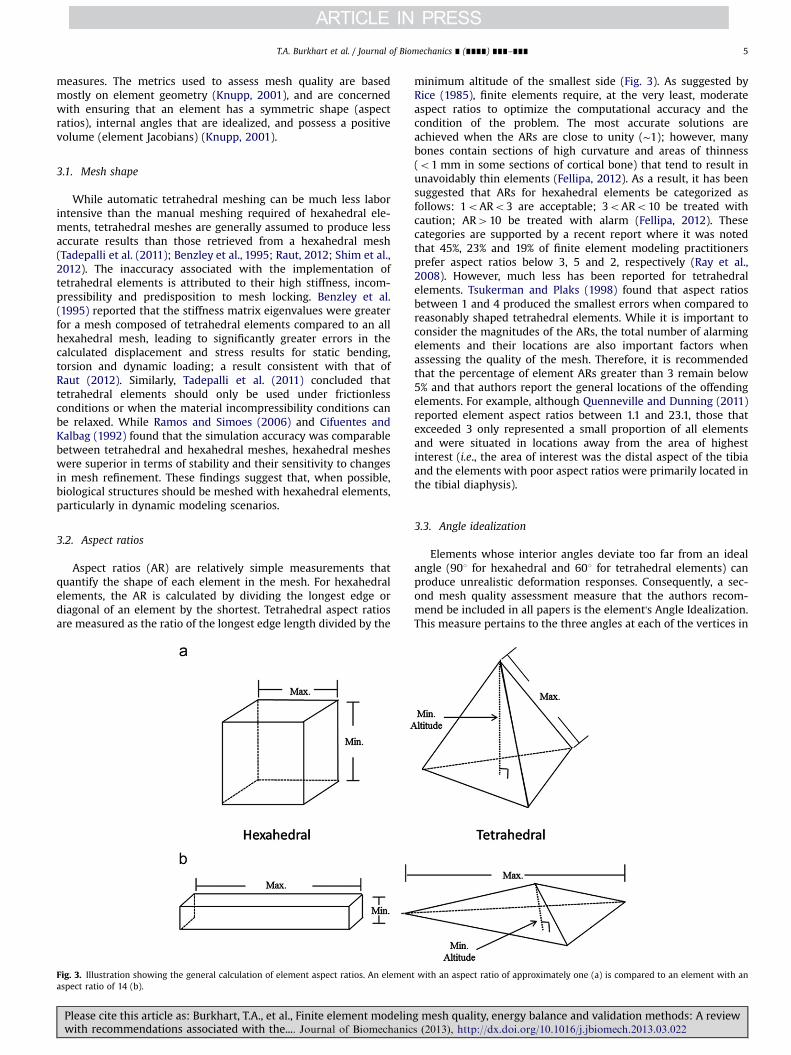
Aspect ratios (AR) are relatively simple measurements thatquantify the shape of each element in the mesh. For hexahedralelements, the AR is calculated by dividing the longest edge ordiagonal of an element by the shortest. Tetrahedral aspect ratiosare measured as the ratio of the longest edge length divided by the
Fig. 3. Illustration showing the general calculation of element aspect ratios. An elemenaspect ratio of 14 (b).
Please cite this article as: Burkhart, T.A., et al., Finite element modelinwith recommendations associated with the.... Journal of Biomechanic
minimum altitude of the smallest side (Fig. 3). As suggested byRice (1985), finite elements require, at the very least, moderateaspect ratios to optimize the computational accuracy and thecondition of the problem. The most accurate solutions areachieved when the ARs are close to unity (∼1); however, manybones contain sections of high curvature and areas of thinness(o1 mm in some sections of cortical bone) that tend to result inunavoidably thin elements (Fellipa, 2012). As a result, it has beensuggested that ARs for hexahedral elements be categorized asfollows: 1oARo3 are acceptable; 3oARo10 be treated withcaution; AR410 be treated with alarm (Fellipa, 2012). Thesecategories are supported by a recent report where it was notedthat 45%, 23% and 19% of finite element modeling practitionersprefer aspect ratios below 3, 5 and 2, respectively (Ray et al.,2008). However, much less has been reported for tetrahedralelements. Tsukerman and Plaks (1998) found that aspect ratiosbetween 1 and 4 produced the smallest errors when compared toreasonably shaped tetrahedral elements. While it is important toconsider the magnitudes of the ARs, the total number of alarmingelements and their locations are also important factors whenassessing the quality of the mesh. Therefore, it is recommendedthat the percentage of element ARs greater than 3 remain below5% and that authors report the general locations of the offendingelements. For example, although Quenneville and Dunning (2011)reported element aspect ratios between 1.1 and 23.1, those thatexceeded 3 only represented a small proportion of all elementsand were situated in locations away from the area of highestinterest (i.e., the area of interest was the distal aspect of the tibiaand the elements with poor aspect ratios were primarily located inthe tibial diaphysis).
3.3. Angle idealization
Elements whose interior angles deviate too far from an idealangle (901 for hexahedral and 601 for tetrahedral elements) canproduce unrealistic deformation responses. Consequently, a sec-ond mesh quality assessment measure that the authors recom-mend be included in all papers is the element's Angle Idealization.This measure pertains to the three angles at each of the vertices in
t with an aspect ratio of approximately one (a) is compared to an element with an
g mesh quality, energy balance and validation methods: A reviews (2013), http://dx.doi.org/10.1016/j.jbiomech.2013.03.022i

Fig. 4. Illustration showing an example of three element angles that are calculated at each of the eight nodes, resulting in 24 total angle measures.
T.A. Burkhart et al. / Journal of Biomechanics ∎ (∎∎∎∎) ∎∎∎–∎∎∎6
hexahedral and tetrahedral elements, which are created by theintersection of each pair of edges (24 angle measurements perhexahedral element and 12 per tetrahedral) (Fig. 4). For hexahe-dral elements, Liu et al. (2007) suggest that the interior angledeviations should not theoretically exceed 901 (absolute angle of1801), but in practice, should be within 301 of deviation (absoluteangle of 1201). Holmes (1994) suggested a similarly conservativecriteria noting that mesh quality is primarily related to the numberof elements whose interior angles deviate by more than 451 fromperpendicular. However, similar to the problem with aspect ratios,modeling bone anatomies with areas of high curvatures willundoubtedly require some misshapen elements that exceed 451of distortion. Therefore, it is suggested that an element's angleidealization may be considered satisfactory providing that lessthan 5% of internal angle deviations exceed 701 (absoluteangleso1601) (El-Hamalawi, 2000; Quenneville and Dunning,2011; Ray et al., 2008). In terms of tetrahedral elements, there isvery little published data on the size of acceptable dihedral angles,but it appears that angles between 301 and 1501 will produce arelatively accurate mesh (Klinger and Shewchuck, 2007.)
3.4. Element Jacobians
Element Jacobians provide a measure of volume distortion froman ideally shaped element and represent the determinant of theJacobian matrix (which itself contains information regarding thevolume, shape and orientation of the element) (Knupp, 2001)(Fig. 5). Specifically, the Jacobian matrix defines the mapping ofelement vertices from the ideally-shaped element to the actualelement (Knupp, 2000). The Jacobian of an extremely distorted (i.e., inverted) element is negative and will prevent an analysis fromcontinuing (Zhang et al., 2010; Knupp, 2007). The literaturepertaining to element Jacobians suggests that the assessment oftetrahedral and hexahedral elements is the same, and can bedescribed by the following criteria: (i) that they be positive invalue (Fellipa, 2012; Knupp, 2007); (ii) preferably greater than0.2 in magnitude (Quenneville and Dunning, 2011; Untaroiu et al.,2005; Li et al., 2011); and (iii) less than 5% of all Jacobians shouldfall below a magnitude of 0.7 (Ray et al., 2008).
As all of these mesh quality measures can significantly affectthe solution of the finite element analysis (despite a successfulmesh sensitivity analysis), it is recommended that authors per-form all of these tests on their mesh and report the findings in thefollowing way:
�
Pw
The type of elements that were chosen to discretize thegeometry and the result of a sensitivity analysis, if one wasconducted (Erdemir et al., 2012), should be reported.
�
The type of mesh quality metrics that were used to assess themesh should be explicitly stated, as well as the criteria thatwere used to determine whether the mesh was acceptable.lease cite this article as: Burkhart, T.A., et al., Finite element modelinith recommendations associated with the.... Journal of Biomechanic
�
The results of the mesh quality assessment should be presentedby first indicating if all of the elements in the mesh passed theanalysis, followed by the percentage of elements (with respectto the total number of elements in the mesh) that did not meetthe assessment criteria. A statement regarding the location ofthe failed elements should also be included.4. Model validation and energy assessment
The confidence in a model to accurately predict real worldphenomena depends on a critical evaluation of the model's resultsagainst experimental data (Oberkampf and Trucano, 2002; Rebbaet al., 2006) in the form of numerical validation. While validationis especially important when the goal of the model is a clinicalapplication (Viceconti et al., 2005; Cristofolini et al., 2010), themethods used to validate past finite element models have variedgreatly (Anderson et al., 2007).
It is the opinion of the authors of the current review thatvalidating a model should involve an analysis of the energiesassociated with the model (especially when evaluating the resultsof dynamic simulations), as well as the engagement of multiplequantitative techniques that compare the model outputs toexperimental findings. This section will summarize the measuresof energy balance and present a number of commonly usedvalidation techniques.
4.1. Energy balance
Model assurance verification (Ray et al., 2008) involves ensuringthat numerical results adhere to the basic physical laws, namely theconservation of energy. At a minimum, the model's global energymustbe checked for balance to make certain that there are no majorinconsistencies in the energy of the system and should be assessed forboth static and dynamic loading conditions. This can be achieved bykeeping the sum of internal, kinetic, sliding, hourglass, system damp-ing, and rigid wall energies (Schinkel-Ivy et al., 2012) within anacceptable range (5%) of the total global energy (Ray et al., 2008).
There are special cases of model energies that require furtherdiscussion, especially related to dynamic modeling applications. Insome finite element simulations (e.g., when implementing con-stant stress element formulations), a phenomenon known as“hourglassing” can occur, where a hexahedral element undergoesa deformation in the absence of strain (Note: the inherent stiffnessof a tetrahedral element prevents it from being prone to hourglas-sing). While this is especially true for dynamic, high deformationsimulations, the effects of hourglassing should be monitored in allsituations as it can lead to inaccurate results and, in severe cases,negative volume elements. While hourglass control can be imple-mented, in which a small elastic stiffness is added (thus gene-rating energy and allowing the elements to resist hourglassing),
g mesh quality, energy balance and validation methods: A reviews (2013), http://dx.doi.org/10.1016/j.jbiomech.2013.03.022i
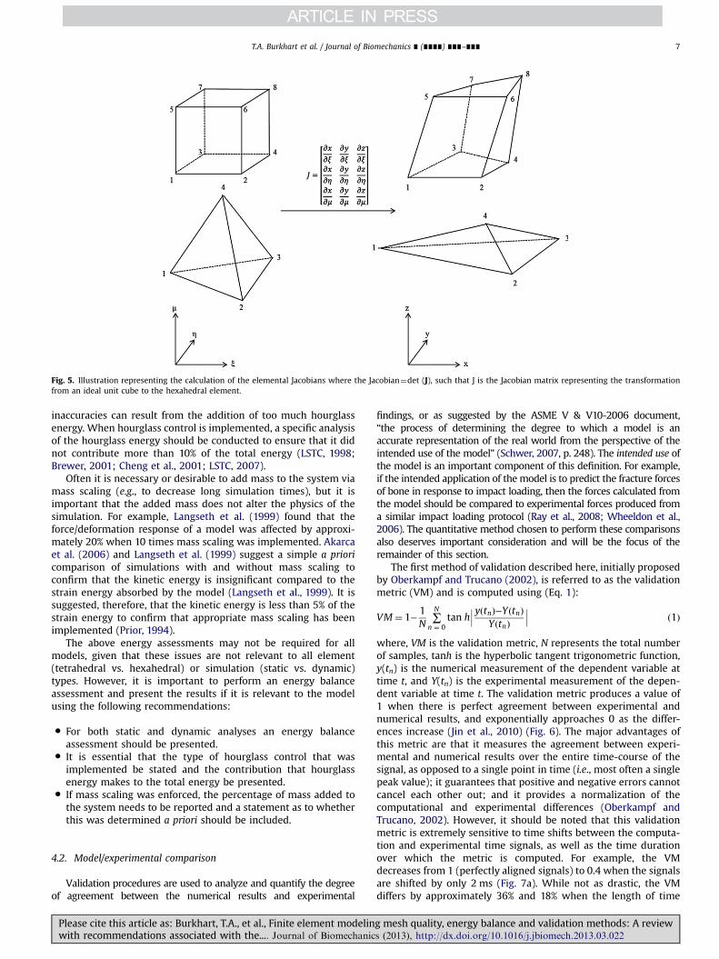
Fig. 5. Illustration representing the calculation of the elemental Jacobians where the Jacobian¼det (J), such that J is the Jacobian matrix representing the transformationfrom an ideal unit cube to the hexahedral element.
T.A. Burkhart et al. / Journal of Biomechanics ∎ (∎∎∎∎) ∎∎∎–∎∎∎ 7
inaccuracies can result from the addition of too much hourglassenergy. When hourglass control is implemented, a specific analysisof the hourglass energy should be conducted to ensure that it didnot contribute more than 10% of the total energy (LSTC, 1998;Brewer, 2001; Cheng et al., 2001; LSTC, 2007).
Often it is necessary or desirable to add mass to the system viamass scaling (e.g., to decrease long simulation times), but it isimportant that the added mass does not alter the physics of thesimulation. For example, Langseth et al. (1999) found that theforce/deformation response of a model was affected by approxi-mately 20% when 10 times mass scaling was implemented. Akarcaet al. (2006) and Langseth et al. (1999) suggest a simple a prioricomparison of simulations with and without mass scaling toconfirm that the kinetic energy is insignificant compared to thestrain energy absorbed by the model (Langseth et al., 1999). It issuggested, therefore, that the kinetic energy is less than 5% of thestrain energy to confirm that appropriate mass scaling has beenimplemented (Prior, 1994).
The above energy assessments may not be required for allmodels, given that these issues are not relevant to all element(tetrahedral vs. hexahedral) or simulation (static vs. dynamic)types. However, it is important to perform an energy balanceassessment and present the results if it is relevant to the modelusing the following recommendations:
�
Pw
For both static and dynamic analyses an energy balanceassessment should be presented.
�
It is essential that the type of hourglass control that wasimplemented be stated and the contribution that hourglassenergy makes to the total energy be presented.�
If mass scaling was enforced, the percentage of mass added tothe system needs to be reported and a statement as to whetherthis was determined a priori should be included.4.2. Model/experimental comparison
Validation procedures are used to analyze and quantify the degreeof agreement between the numerical results and experimental
lease cite this article as: Burkhart, T.A., et al., Finite element modelinith recommendations associated with the.... Journal of Biomechanic
findings, or as suggested by the ASME V & V10-2006 document,“the process of determining the degree to which a model is anaccurate representation of the real world from the perspective of theintended use of the model” (Schwer, 2007, p. 248). The intended use ofthe model is an important component of this definition. For example,if the intended application of themodel is to predict the fracture forcesof bone in response to impact loading, then the forces calculated fromthe model should be compared to experimental forces produced froma similar impact loading protocol (Ray et al., 2008; Wheeldon et al.,2006). The quantitative method chosen to perform these comparisonsalso deserves important consideration and will be the focus of theremainder of this section.
The first method of validation described here, initially proposedby Oberkampf and Trucano (2002), is referred to as the validationmetric (VM) and is computed using (Eq. 1):
VM¼ 1−1N
∑N
n ¼ 0tan h
��� yðtnÞ−YðtnÞYðtnÞ
��� ð1Þ
where, VM is the validation metric, N represents the total numberof samples, tanh is the hyperbolic tangent trigonometric function,y(tn) is the numerical measurement of the dependent variable attime t, and Y(tn) is the experimental measurement of the depen-dent variable at time t. The validation metric produces a value of1 when there is perfect agreement between experimental andnumerical results, and exponentially approaches 0 as the differ-ences increase (Jin et al., 2010) (Fig. 6). The major advantages ofthis metric are that it measures the agreement between experi-mental and numerical results over the entire time-course of thesignal, as opposed to a single point in time (i.e., most often a singlepeak value); it guarantees that positive and negative errors cannotcancel each other out; and it provides a normalization of thecomputational and experimental differences (Oberkampf andTrucano, 2002). However, it should be noted that this validationmetric is extremely sensitive to time shifts between the computa-tion and experimental time signals, as well as the time durationover which the metric is computed. For example, the VMdecreases from 1 (perfectly aligned signals) to 0.4 when the signalsare shifted by only 2 ms (Fig. 7a). While not as drastic, the VMdiffers by approximately 36% and 18% when the length of time
g mesh quality, energy balance and validation methods: A reviews (2013), http://dx.doi.org/10.1016/j.jbiomech.2013.03.022i

Fig. 6. The validation metric as a function of the relative error between the modeland experimental data (Adapted from Oberkampf and Trucano, 2002; Jin et al.,2010).
Fig. 7. Sensitivity of the validation metric to signal shifts (a) and the duration overwhich the validation metric is calculated (b).
Fig. 8. An example of the model axial force signal (Burkhart et al., 2012) incomparison to the un-scaled force corridors (mean72SD).
T.A. Burkhart et al. / Journal of Biomechanics ∎ (∎∎∎∎) ∎∎∎–∎∎∎8
over which the metric is calculated is 1.5 times less and greaterthan the full length of the signal (20 ms as measured from theonset and cessation of the impulse), respectively (Fig. 7b).
Data corridors or ensemble averages are another popularmodel validation method that produce data boundaries based onthe mean and standard deviation of a dataset, and to some extent,describes the level of generalizability of the numerical results(Fig. 8) (Bir et al., 2004; Craig et al., 2008). While a relativelysimple procedure, there are a few systematic phases that shouldbe adhered to when generating the most accurate corridors.Depending on the purpose of the model and the variability ofthe experimental specimens, it may be necessary to scale the dataaccording to mass (e.g., application to a small female). Data scaling
Please cite this article as: Burkhart, T.A., et al., Finite element modelinwith recommendations associated with the.... Journal of Biomechanic
allows for the normalization of each specimen's with respect to anindividual of a pre-determined size (e.g., normalizing an impactforce to the mass of a 5th percentile female). The process of datascaling will not be presented herein, but a thorough description ofthe procedure can be found in Eppinger et al. (1984), Mertz (1984),Yoganandan and Pintar (2005) and Masson et al. (2005). Once thedata have been scaled, it is necessary to ensure that time varyingsignals are properly aligned, which can be accomplished one oftwo ways. First, the signals can be aligned according to signalonset (most commonly a force impulse). A second, more elaboratetechnique, involves iteratively aligning the signals to a pre-determined characteristic signal with the goal of minimizing thecumulative variance (Masson et al., 2005; Yoganandan and Pintar,2005). Following signal alignment, the upper and lower bound-aries of the corridors are calculated by adding and subtracting oneor two standard deviations from the mean, respectively. Thecorridors can now serve as a validation method by ensuring thenumerical results fall within the calculated boundaries.
While often overlooked, the level of agreement between modeland experimental data can also be handled with statisticaltechniques, with two of the more common methods being anerror assessment and correlation analyses. Error assessments arerelatively simple methods that quantify the differences betweensome value (often the peak value of a signal) measured experi-mentally and by the model. Two commonly used techniques arepercentage errors (Moore et al., 2010; Kim et al., 2009) and rootmean squared errors (Torcasio et al., 2012). Correlation analysesare often presented as the Pearson correlation coefficient andprovide a measure of the relationship between the experimentaland model data. However, it has been noted that while correlationanalysis provides a measure of the strength of the relationship,they are not necessarily good measures of agreement (Bland andAltman, 1986; Chan, 2003). Bland and Altman (1986) and Chan(2003) argue that a change in scale will affect the agreement butnot the correlation, and variables that have weak agreement oftenshow strong correlation. For example, strains associated with aparticular location in a model can be compared to direct measuresof strain from an experimental strain gauge (e.g., Burkhart, 2012).It would be logical therefore, that the strains measured by thesetwo different methods would be significantly related, despite thepossibility of being in poor agreement. An alternate, more robustmeasure of agreement is the difference plot, otherwise known as aBland–Altman plot (Bland and Altman, 1986; Chan, 2003; Mylesand Cui, 2007; Motulsky, 2003; Austman et al., 2008). A Bland–Altman plot is constructed by first computing the differencesbetween the experimental and model data points and plottingthese against the mean of the same paired values, with limitsof agreement determined based on the mean71.96 SD. Finally,
g mesh quality, energy balance and validation methods: A reviews (2013), http://dx.doi.org/10.1016/j.jbiomech.2013.03.022i
T.A. Burkhart et al. / Journal of Biomechanics ∎ (∎∎∎∎) ∎∎∎–∎∎∎ 9
the precision of agreement is assessed by calculating the standarderrors of the bias (Eq. 2) and upper and lower limits of agreement(Eq. 3) and subsequently constructing 95% confidence intervals(Eqs. 4–6) (Bland and Altman, 1986)
SEbias ¼ffiffiffiffiffiS2
n
sð2Þ
SElimits ¼ffiffiffiffiffiffiffiffi3S2
n
sð3Þ
bias−ðt0:05 � SEbiasÞ to biasþ ðt0:05 � SEbiasÞ ð4Þ
upper limit−ðt0:05 � SEupper limitÞ to upper limitþ ðt0:05 � SEupper limitÞ ð5Þ
lower limit−ðt0:05 � SElower limitÞ to lower limitþ ðt0:05 � SElower limitÞ ð6Þ
Where, SE is the respective standard error, S is the standarddeviation and n is the number of samples. Based on thesemeasures, three criteria must be considered: (i) the significanceof the bias, which should be addressed in terms of the model'sapplication, and is therefore not a statistical question but a clinicalone (Motulsky, 2003; Chan, 2003); (ii) 95% of the values should fallwithin the limits of agreement (Bland and Altman, 1986), and(iii) the standard errors of the bias and limits of agreementthemselves should be small (Bland and Altman, 1986; Chan, 2003).
Finally, model validation should not be considered completeunless the issue of intended use is addressed, which should includesome comparison that takes into consideration the full applicationof the model. For example, finite element models of the foot weredeveloped to measure the pressure distribution between the footand supporting surface (Qiu et al., 2011; Hsu et al., 2008; Chenet al., 2010) and therefore, the pattern of pressure through thefoot, predicted by the model, was directly compared to experi-mental pressures determined by an in-shoe pressure sensingsystem. Similarly, models developed to predict bone fractureshould include a comparison of the location and intensity offracture within the model to that found experimentally(Quenneville and Dunning, 2011).
With respect to model validation the following should bereported:
�
Pw
The specific methods that are used to validate the modelagainst experimental results, and from where the experimentaldata were derived (i.e., previously published data vs. experi-mental data related to the specimen(s)/participant(s) used tocreate the model).
�
If the validation metric is being used, details regarding thevalidation period (start and end points of validation), and howthe experimental and numerical signals were initially aligned,should be included.�
Specific details related to all statistical methods used need to bereported, similar to the statistical reporting required for anexperimental investigation.�
At least one of the validation methods should be a representa-tion of the intended use of the model and a summary andinterpretation of the validation results (including the details ofthe measurement method).5. Summary
Anderson et al. (2007), Cristofolini et al. (2010) and Erdemir et al.(2012), Henninger et al. (2010) and Jones and Wilcox (2008) presentan excellent framework regarding validation and verification of
lease cite this article as: Burkhart, T.A., et al., Finite element modelinith recommendations associated with the.... Journal of Biomechanic
computational models and what should be reported when presentingresearch conducted using this very powerful research tool; readers areencouraged to consult these works when developing and utilizingfinite element models for orthopedic and biomechanics research.However, these articles introduce validation and verification proce-dures in a broad sense, and present general reporting guidelines thatdo not address mesh quality or energy balance issues. Therefore, thispaper presents a review of specific mesh quality and energy balanceassessments, as well as model validation methods, as they relate tofinite element models of biological structures (specifically bone andsoft tissues). While the authors of this paper attempted to includecriteria that would indicate a high quality mesh and a valid model, thepaucity of work in this area limited the generation of a comprehensiveset of generalized modeling criteria. The lack of validation, meshquality and energy balance evidence provided in the literature to dateis unfortunate, particularly given the recent popularity and power offinite element modeling approaches in biomechanics and orthopedicsresearch. Therefore, future work needs to be directed at establishingmore definitive validation limits for all modeling applications so thataccuracy can be optimized and finite element models more acceptedfor clinical applications.
Conflict of interest statement
The authors have no conflicts of interest to declare.
Acknowledgments
This work was partially supported by the Joint Motion Program(JuMP)—A CIHR Training Program in Musculoskeletal HealthResearch and Leadership, the Natural Sciences and EngineeringResearch Council of Canada and Western University. We wouldalso like to acknowledge and thank Dr. William Altenhof for hisvaluable insight.
References
Akarca, S.S., Altenhof, W.J., Alpas, A.T., 2006. Finite element analysis of slidingcontact between a circular asperity and an elastic surface in plane straincondition. In: Proceedings of the International LS-DYNA Users Conference,Detroit, MI.
de Almeida, E.O., Rocha, E.P., Assuncao, W.G., Junior, A.C., Anchieta, R.B., 2011.Cortical bone stress distribution in mandibles with different configurationsrestored with prefabricated bar-prosthesis protocol: a three-dimensional finite-element analysis. Journal of Prosthodontics: Official Journal of the AmericanCollege of Prosthodontists 20, 29–34.
Anderson, D.D., Deshpande, B.R., Daniel, T.E., Baratz, M.E., 2008. A three dimen-sional finite element model of the radiocarpal joint: distal radius fracture step-off and stress transfer. Iowa Orthopedic Journal, 108–117.
Anderson, D.D., Goldsworthy, J.K., Wendy, L., Rudert, J.M., Tochigi, Y., Brown, T.D.,2007. Physical validation of a patient-specific contact finite element model ofthe ankle. Journal of Biomechanics 40, 1662–1669.
Anderson, A.E., Ellis, B.J., Maas, S.A., Peters, C.L., Weiss, J.A., 2008. Validation of finiteelement predictions of cartilage contact pressure in the human hip joint.Journal of Biomechanical Engineering 130, 051008.
Anderson, A.E., Ellis, B.J., Weiss, J.A., 2007. Verification, validation and sensitivitystudies in computational biomechanics. Computer Methods in Biomechanicsand Biomedical Engineering 10, 171–184.
Austman, R.L., Milner, J.S., Holdsworth, D.W., Dunning, C.E., 2008. The effect of thedensity-modulus relationship selected to apply material properties in a finiteelement model of long bone. Journal of Biomechanics 41, 3171–3176.
Benzley, S. E., Perry, E., Merkley, K., Clark, B., Sjaardama, G., 1995. A comparision ofall hexagonal and all tetrahedral finite element meshes for elastic and elasto-plastic analysis. In: Proceedings of the 4th International Meshing Roundtable,Albuquerque, NM.
Bir, C., Viano, D., King, A., 2004. Development of biomechanical response corridorsof the thorax to blunt ballistic impacts. Journal of Biomechanics 37, 73–79.
Bland, M.J., Altman, D.G., 1986. Statistical methods for assessing agreementbetween two methods of clinical measurement. Lancet i, 307–310.
Boutroy, S., Van Rietbergen, B., Sornay-Rendu, E., Munoz, F., Bouxsein, M.L., Delmas,P.D., 2008. Finite element analysis based on in vivo HR-pQCT images of thedistal radius is associated with wrist fracture in postmenopausal women.
g mesh quality, energy balance and validation methods: A reviews (2013), http://dx.doi.org/10.1016/j.jbiomech.2013.03.022i
T.A. Burkhart et al. / Journal of Biomechanics ∎ (∎∎∎∎) ∎∎∎–∎∎∎10
Journal of Bone and Mineral Research: The Official Journal of the AmericanSociety for Bone and Mineral Research 23, 392–399.
Brewer, J.C., 2001. Effects of angles and offsets in crash simulations of automobileswith light trucks. In: Proceedings of the Conference on Enhanced Safety ofVehicles, Amsterdam, Netherlands.
Buchanan, D., Ural, A., 2010. Finite element modeling of the influence of handposition and bone properties on the Colles' fracture load during a fall. Journal ofBiomechanical Engineering 132, 081007.
Buchler, P., Ramaniraka, N.A., Rakotomanana, L.R., Iannotti, J.P., Farron, A., 2002. Afinite element model of the shoulder: application to the comparison of normaland osteoarthritic joints. Clinical Biomechanics (Bristol, Avon) 17, 630–639.
Budhabhatti, S.P., Erdemir, A., Petre, M., Sferra, J., Donley, B., 2007. Finite elementmodeling of the first ray of the foot: a tool for the design of interventions.Journal of Biomechanical Engineering 129, 750–756.
Burkhart, T. A., 2012. Biomechanics of the upper extremity in response to dynamicimpact loading indicative of a forward fall: An Experimental and NumericalInvestigation. Ph.D. Dissertation. University of Windsor, Windsor Ontario,Canada.
Carrigan, S.D., Whiteside, R.A., Pichora, D.R., Small, C.F., 2003. Development of athree-dimensional finite element model for carpal load transmission in a staticneutral posture. Annals of Biomedical Engineering 31, 718–725.
Chamoret, D., Roth, S., Feng, Z.Q., Yan, X.T., Gomes, S., Peyraut, F., 2011. A novelapproach to modeling and simulating the contact behavior between a humanhand model and a deformable object. Computer Methods in Biomechanics andBiomedical Engineering.
Chan, Y.H., 2003. Biostatistics 104: Correlation analysis. Singapore Medical Journal44, 614–619.
Chen, W., Lee, T., Lee, P.V., Lee, J.W., Lee, S., 2010. Effects of internal stressconcentrations in plantar soft tissue—a preliminary three-dimensional finiteelement analysis. Medical Engineering and Physics 32, 324–331.
Cheng, H.K., Lin, C., Wang, H., Chou, S., 2008. Finite element analysis of plantarfascia under stretch-the relative contribution of windlass mechanism andAchilles tendon force. Journal of Biomechanics 41, 1937–1944.
Cheng, Z.Q., Thacker, J.G., Pilkey, W.D., Hollowell, W.T., Reagan, S.W., Sieveka, E.M.,2001. Experiences in reverse-engineering of a finite element automobile crashmodel. Finite Element Analysis and Design 37, 843–860.
Chennimalai Kumar, N., Dantzig, J.A., Jasiuk, I.M., Robling, A.G., Turner, C.H., 2010.Numerical modeling of long bone adaptation due to mechanical loading:correlation with experiments. Annals of Biomedical Engineering 38, 594–604.
Cheung, J.T., Zhang, M., Leung, A.K., Fan, Y., 2005. Three-dimensional finite elementanalysis of the foot during standing-a material sensitivity study. Journal ofBiomechanics 38, 1045–1054.
Chosa, E., Goto, K., Totoribe, K., Tajima, N., 2004. Analysis of the effect of lumbarspine fusion on the superior adjacent intervertebral disk in the presence of diskdegeneration, using the three-dimensional finite element method. Journal ofSpinal Disorders and Techniques 17, 134–139.
Cifuentes, A.O., Kalbag, A., 1992. A performance study of tetrahedral and hexahedralelements in 3-D finite element structural analysis. Finite Element Analysis andDesign 12, 313–318.
Clausen, J.D., Goel, V.K., Traynelis, V.C., Scifert, J., 1997. Uncinate processes andLuschka joints influence the biomechanics of the cervical spine: quantificationusing a finite element model of the C5-C6 segment. Journal of OrthopedicResearch: Official Publication of the Orthopedic Research Society 15, 342–347.
Clavert, P., Zerah, M., Krier, J., Mille, P., Kempf, J.F., Kahn, J.L., 2006. Finite elementanalysis of the strain distribution in the humeral head tubercles duringabduction: comparison of young and osteoporotic bone. Surgical and Radi-ologic Anatomy: SRA 28, 581–587.
Craig, M., Bir, C., Viano, D., Tashman, S., 2008. Biomechanical response of the humanmandible to impacts of the chin. Journal of Biomechanics 41, 2972–2980.
Cristofolini, L., Schileo, E., Juszcyyk, M., Taddei, F., Martelli, S., Viceconti, M., 2010.Mechanical Testing of bones: the positive synergy of finite element models andin vitro experiments. Philosophical Transactions of the Royal Society A:Mathematical, Physical & Engineering Sciences 368, 2725–2763.
Debski, R.E., Weiss, J.A., Newman, W.J., Moore, S.M., McMahon, P.J., 2005. Stress andstrain in the anterior band of the inferior glenohumeral ligament during a simulatedclinical examination. Journal of Shoulder and Elbow Surgery 14, 24S–31S.
Edwards, W.B., Troy, K.L., 2012. Finite element prediction of surface strain andfracture strength at the distal radius. Medical Engineering & Physics 34,290–298.
Eichenseer, P.H., Sybert, D.R., Cotton, J.R., 2011. A finite element analysis of sacroiliacjoint ligaments in response to different loading conditions. Spine 36, E1446–52.
El-Hamalawi, A., 2000. A simple and effective element distortion factor. Computersand Structures 75, 507–513.
Ellis, B.J., Debski, R.E., Moore, S.M., McMahon, P.J., Weiss, J.A., 2007. Methodologyand sensitivity studies for finite element modeling of the inferior glenohumeralligament complex. Journal of Biomechanics 40, 603–612.
Eppinger, H. R., Marcus, H. J., Morgan, M. M., 1984. Development of dummy andinjury index for NHTSA's thoracis side impact protection research program.Government/Industry meeting and exposition. In: Proceedings of Stapp CarCrash Conference, Washington, DC, USA.
Erdemir, A., Guess, T.M., Halloran, J., Tadepalli, S.C., Morrison, T.M., 2012. Con-siderations for reporting finite element analysis studies in biomechanics.Journal of Biomechanics 45, 625–633.
Fellipa, C., 2012. FEM modeling: Mesh, Loads and BCs, Chapter 7. University ofColorado, pp. 1–19, downloaded from ⟨http://www.colorado.edu/engineering/cas/courses.d/IFEM.d/IFEM.Ch07.d/IFEM.Ch07.index.html⟩.
Please cite this article as: Burkhart, T.A., et al., Finite element modelinwith recommendations associated with the.... Journal of Biomechanic
Galbusera, F., Schmidt, H., Noailly, J., Malandrino, A., Lacroix, D., Wilke, H.J., Shirazi-Adl, A., 2011. Comparison of four methods to simulate swelling in poroelasticfinite element models of intervertebral discs. Journal of the MechanicalBehavior of Biomedical Materials 4, 1234–1241.
Gatti, C.J., Maratt, J.D., Palmer, M.L., Hughes, R.E., Carpenter, J.E., 2010. Developmentand validation of a finite element model of the superior glenoid labrum. Annalsof Biomedical Engineering 38, 3766–3776.
Gislason, M.K., Nash, D.H., Nicol, A., Kanellopoulos, A., Bransby-Zachary, M., Hems,T., Condon, B., Stansfield, B., 2009. A three-dimensional finite element model ofmaximal grip loading in the human wrist. Proceedings of the Institution ofMechanical Engineers. Part H, Journal of Engineering in Medicine 223, 849–861.
Goske, S., Erdemir, A., Petre, M., Budhabhatti, S., Cavanagh, P.R., 2006. Reduction ofplantar heel pressures: Insole design using finite element analysis. Journal ofBiomechanics 39, 2363–2370.
Gu, Y.D., Ren, X.J., Li, J.S., Lake, M.J., Zhang, Q.Y., Zeng, Y.J., 2010. Computersimulation of stress distribution in the metatarsals at different inversionlanding angles using the finite element method. International Orthopedics34, 669–676.
Guo, L.X., Zhang, Y.M., Zhang, M., 2011. Finite element modeling and modal analysisof the human spine vibration configuration. IEEE Transactions on Bio-MedicalEngineering 58, 2987–2990.
Guo, X., Fan, Y., Li, Z.M., 2009. Effects of dividing the transverse carpal ligament onthe mechanical behavior of the carpal bones under axial compressive load: afinite element study. Medical Engineering & Physics 31, 188–194.
Gupta, S., van der Helm, F.C., Sterk, J.C., van Keulen, F., Kaptein, B.L., 2004.Development and experimental validation of a three-dimensional finite ele-ment model of the human scapula. Proceedings of the Institution of MechanicalEngineers. Part H, Journal of Engineering in Medicine 218, 127–142.
Hamed, E., Jasiuk, I., Yoo, A., Lee, Y., Liszka, T., 2012. Multi-scale modeling of elasticmoduli of trabecular bone. Journal of the Royal Society, Interface/the RoyalSociety 9, 1654–1673.
Henninger, H.B., Reese, S.P., Anderson, A.E., Weiss, J.A., 2010. Validation of computationalmodels in biomechanics. Proceedings of the Institution of Mechanical Engineers,Part H: Journal of Engineering in Medicine 224, 801–812.
Holmes, D.I., 1994. Generalized method of decomposing solid geometry into hexahe-dron finite elements. In International Meshing Roundtable, Albuquerque, NM.
Hopkins, A.R., Hansen, U.N., Amis, A.A., Taylor, M., Gronau, N., Anglin, C., 2006.Finite element modeling of glenohumeral kinematics following total shoulderarthroplasty. Journal of Biomechanics 39, 2476–2483.
Hsu, Y., Gung, Y., Shih, S., Feng, C., Wei, S., Yu, C., Chen, C., 2008. Using optimizationapproach to design an insole for lowering plantar fascia stress—a finite elementstudy. Annals of Biomedical Engineering 36, 1345–1352.
Hussain, M., Natarajan, R.N., An, H.S., Anderson, G.B., 2010. Motion changes inadjacent segments due to moderate and severe degeneration in C5-C6 disc: aporoelastic C3-T1 finite element model study. Spine 35, 939–947.
Jamshidi, N., Hanife, H., Rostami, M., Najarian, S., Menhaj, M.B., Saadatnia, M.,Salami, F., 2010. Modeling the interaction of ankle-foot orthosis and foot byfinite element methods to design an optimized sole in steppage gait. Journal ofMedical Engineering & Technology 34, 116–123.
Jin, S.Y., Majumder, A., Altenhof, W.J., Green, D., 2010. Axial cutting of AA6061-T6circular extrusions under impact using single- and dual-cutter configurations.International Journal of Impact Engineering 37, 735–753.
Jing, D., Ashton-Miller, J.A., DeLancey, J.O., 2012. A subject-specific anisotropicvisco-hyperelastic finite element model of female pelvic floor stress and strainduring the second stage of labor. Journal of Biomechanics 45, 455–460.
Jones, A.C., Wilcox, R.K., 2008. Finite element analysis of the spine: towards aframework of verification, validation and sensitivity analysis. Medical Engineer-ing and Physics 30, 1287–1304.
Kim, J.E., Li, Z., Ito, Y., Huber, C.D., Shih, A.M., Eberhardt, A.W., Yang, K.H., King, A.I., Soni, B.K., 2009. Finite element model development of a child pelvis with optimization-based material identification. Journal of Biomechanics 42, 2191–2195.
Klinger, B.M., Shewchuck, J.R., 2007. Aggressive tetrahedral mesh improvement. In16th International Meshing Roundtable, Seattle, WA.
Knupp, P. M., 2007. Remarks on mesh quality. In: Proceedings of the 45th AIAAAerospace Sciences Meeting and Exhibit, Reno, NV.
Knupp, P.M., 2001. Algebraic mesh quality metrics. SIAM Journal on ScientificComputing 23, 193–218.
Knupp, P.M., 2000. Achieving finite element mesh quality via optimization of theJacobian matrix norm and associated quantities. Part II-A framework forvolume mesh optimization and the condition number of the Jacobian matrix.International Journal for Numerical Methods in Engineering 48, 1165–1185.
Kotha, S.P., Hsieh, Y.F., Strigel, R.M., Muller, R., Silva, M.J., 2004. Experimental andfinite element analysis of the rat ulnar loading model-correlations betweenstrain and bone formation following fatigue loading. Journal of Biomechanics37, 541–548.
Krywonos, J., Fenwick, J., Elkut, F., Jenkinson, I., Liu, Y.H., Brunt, J.N., Scott, A., Malik,Z., Eswar, C., Ren, X.J., 2010. MRI image-based FE modeling of the pelvis systemand bladder filling. Computer Methods in Biomechanics and BiomedicalEngineering 13, 669–676.
Kunze, M., Schaller, A., Steinke, H., Scholz, R., Voigt, C., 2012. Combined multi-bodyand finite element investigation of the effect of the seat height on acetabularimplant stability during the activity of getting up. Computer Methods andPrograms in Biomedicine 105, 175–182.
Langseth, M., Hopperstad, O.S., Berstad, T., 1999. Crashworthiness of aluminumextrusions: validation of numerical simulation, effect of mass ratio and impactvelocity. International Journal of Impact Engineering 22, 829–854.
g mesh quality, energy balance and validation methods: A reviews (2013), http://dx.doi.org/10.1016/j.jbiomech.2013.03.022i
T.A. Burkhart et al. / Journal of Biomechanics ∎ (∎∎∎∎) ∎∎∎–∎∎∎ 11
Ledoux, P., Lamblin, D., Targowski, R., 2001. Modifications to the mechanicalbehavior of the wrist after fracture of the scaphoid. Modeling by finite elementanalysis. Acta Orthopaedica Belgica 67, 236–241.
Li, Z., Hu, J., Reed, M.P., Rupp, J.D., Hoff, C.N., Zhang, J., Cheng, B., 2011. Development,validation, and application of a parametric pediatric head finite element modelfor impact simulations. Annals of Biomedical Engineering 39, 2984–2997.
Liu, G.R., Dai, K.Y., Nguyen, T.T., 2007. A smoothed finite element method formechanics problems. Computational Mechanics 39, 859–877.
LSTC, 2007. Users Manual. Livermore, California, USA.LSTC, 1998. Theoretical Manual. Livermore California, USA.Lund, M.E., de Zee, M., Andersen, M.S., Rasmussen, J., 2012. On validation of
multibody musculoskeletal models. Proceedings of the Institution of Mechan-ical Engineers. Part H: Journal of Engineering in Medicine 226, 82–94.
Lu, Y., Thiagarajan, G., Nicolella, D.P., Johnson, M.L., 2012. Load/strain distributionbetween ulna and radius in the mouse forearm compression loading model.Medical Engineering & Physics 34, 350–356.
MacNeil, J.A., Adachi, J.D., Goltzman, D., Josse, R.G., Kovacs, C.S., Prior, J.C., Olszynski, W.,Davison, K.S., Kaiser, S.M., 2012. CaMos Research Group, 2012. Predicting fractureusing 2D finite element modeling. Medical Engineering & Physics 34, 478–484.
Macneil, J.A., Boyd, S.K., 2008. Bone strength at the distal radius can be estimatedfrom high-resolution peripheral quantitative computed tomography and thefinite element method. Bone 42, 1203–1213.
Massey, C.J., van Donkelaar, C.C., Vresilovic, E., Zavaliangos, A., Marcolongo, M.,2012. Effects of aging and degeneration on the human intervertebral discduring the diurnal cycle: a finite element study. Journal of OrthopedicResearch: Official Publication of the Orthopedic Research Society 30, 122–128.
Masson, C., Arnoux, P., Brunet, C., Cesari, D., 2005. Pedestrian injury mechanisms &criteria: a coupled experimental and finite element approach. In: Proceedingsof SAE–ESV Conference, Washington, DC, USA.
Mertz, J.H., 1984. A procedure for normalizing impact response data. In: Proceed-ings of the Stapp Car Crash Conference, Chicago, IL, USA.
Merz, B., Eckstein, F., Hillebrand, S., Putz, R., 1997. Mechanical implications ofhumero-ulnar incongruity—finite element analysis and experiment. Journal ofBiomechanics 30, 713–721.
Moore, S.M., Ellis, B., Weiss, J.A., McMahon, P.J., Debski, R.E., 2010. The glenohum-eral capsule should be evaluated as a sheet of fibrous tissue: a validated finiteelement model. Annals of Biomedical Engineering 38, 66–76.
Motulsky, H., 2003. Prism 4.0 statistics guide—Statistical analysis for laboratory andclinical researchers. GraphPad Software Inc, San Diego California, USA.
Myles, P.S., Cui, J., 2007. Using the Bland–Altman method to measure agreementwith repeated measures. British Journal of Anaesthesia 99, 309–311.
Noailly, J., Ambrosio, L., Elizabeth Tanner, K., Planell, J.A., Lacroix, D., 2012. In silicoevaluation of a new composite disc substitute with a L3-L5 lumbar spine finiteelement model. European Spine Journal: Official Publication of the EuropeanSpine Society, the European Spinal Deformity Society, and the European Sectionof the Cervical Spine Research Society 21 (Suppl 5), 675–687.
Oberkampf, W.L., Trucano, T.G., 2002. Verification and validation in computationalfluid dynamics. Progress in Aerospace Sciences 38, 209–272.
Ozan, F., Yildiz, H., Bora, O.A., Pekedis, M., Ay Coskun, G., Gore, O., 2010. The effect ofhead trauma on fracture healing: biomechanical testing and finite elementanalysis. Acta Orthopaedica Traumatologica Turcica 44, 313–321.
Pang, H., Shiwalkar, A.P., Madormo, C.M., Taylor, R.E., Andriacchi, T.P., Kuhl, E., 2012.Computational modeling of bone density profiles in response to gait: a subject-specific approach. Biomechanics and Modeling in Mechanobiology 11, 379–390.
Panzer, M.B., Fice, J.B., Cronin, D.S., 2011. Cervical spine response in frontal crash.Medical Engineering & Physics 33, 1147–1159.
Panzer, M.B., Myers, B.S., Capehart, B.P., Bass, C.R., 2012. Development of a finiteelement model for blast brain injury and the effects of CSF cavitation. Annals ofBiomedical Engineering 40, 1530–1544.
Pistoia, W., van Rietbergen, B., Lochmuller, E.M., Lill, C.A., Eckstein, F., Ruegsegger, P.,2002. Estimation of distal radius failure load with micro-finite element analysismodels based on three-dimensional peripheral quantitative computed tomo-graphy images. Bone 30, 842–848.
Pistoia, W., van Rietbergen, B., Ruegsegger, P., 2003. Mechanical consequences ofdifferent scenarios for simulated bone atrophy and recovery in the distal radius.Bone 33, 937–945.
Prior, A.M., 1994. Applications of implicit and explicit finite element techniques tometal forming. Journal of Material Processing Technology 45, 649–656.
Qiu, T., Teo, E., Yan, Y., Lei, W., 2011. Finite element modeling of a 3D coupled foot-boot model. Medical Engineering and Physics 33 1228-1223.
Quenneville, C.E., Dunning, C.E., 2011. Development of a finite element model of thetibia for short-duration high-force axial impact loading. Computer Methods inBiomechanics and Biomedical Engineering 14, 205–212.
Ramos, A., Simoes, J.A., 2006. Tetrahedral versus hexahedral finite elements innumerical modeling of the proximal femur. Medical Engineering & Physics 28,916–924.
Raut, P., 2012. Impact of mesh quality parameters on elements such as beam, shelland 3D solid in structural analysis. International Journal of EngineeringResearch Applications 2, 99–103.
Ray, M.H., Mongiardini, M., Atahan, A.O., Plaxico, C.A., Anghileri, M., 2008.Recommended Procedures for Verification and Validation of Computer Simula-tions used for Roadside Safety Applications, 22–24.
Rebba, R., Mahadevan, S., Huang, S., 2006. Validation and error estimation of computa-tional models. Reliability Engineering and Systems Safety 91, 1390–1397.
Rice, J. R., 1985. Is the aspect ratio significant for finite element problems? PurdueUniversity report number: CSD-TR535.
Please cite this article as: Burkhart, T.A., et al., Finite element modelinwith recommendations associated with the.... Journal of Biomechanic
Rogge, R.D., Adams, B.D., Goel, V.K., 2002. An analysis of bone stresses and fixationstability using a finite element model of simulated distal radius fractures. TheJournal of Hand Surgery 27, 86–92.
Saidpour, S.H., 2006. Assessment of carbon fibre composite fracture fixation plateusing finite element analysis. Annals of Biomedical Engineering 34, 1157–1163.
Savoldelli, C., Bouchard, P.O., Loudad, R., Baque, P., Tillier, Y., 2012. Stress distribu-tion in the temporo-mandibular joint discs during jaw closing: a high-resolution three-dimensional finite-element model analysis. Surgical andRadiologic Anatomy: SRA 34, 405–413.
Schinkel-Ivy, A., Altenhof, W.J., Andrews, D.M., 2012. Validation of a full body finiteelement model (THUMS) for running-type impacts to the lower extremity.Computer Methods in Biomechanics and Biomedical Engineering , http://dx.doi.org/10.1080/10255842.2012.672562.
Schmidt, H., Heuer, F., Drumm, J., Klezl, Z., Claes, L., Wilke, H.J., 2007. Application ofa calibration method provides more realistic results for a finite element modelof a lumbar spinal segment. Clinical Biomechanics (Bristol, Avon) 22, 377–384.
Schwer, L.E., 2007. An overview of the PTC 60/V & V 10: guide for verification andvalidation in computational solid mechanics. Engineering with Computers 23,245–252.
Shim, V.B., Boshme, J., Vaitl, P., Josten, C., Anderson, I.A., 2012. An efficient andaccurate prediction of the stability of percutaneous fixation of acetabularfractures with finite element simulation. Journal of Biomechanical Engineering133, 094501–1-09501-4.
Shim, V.B., Pitto, R.P., Streicher, R.M., Hunter, P.J., Anderson, I.A., 2008. Developmentand validation of patient-specific finite element models of the hemipelvisgenerated from a sparse CT data set. Journal of Biomechanical Engineering 130,051010.
Skalli, W., Robin, S., Lavaste, F., Dubousset, J., 1993. A biomechanical analysis ofshort segment spinal fixation using a three-dimensional geometric andmechanical model. Spine 18, 536–545.
Spyrou, L.A., Aravas, N., 2011. Muscle-driven finite element simulation of humanfoot movements. Computer Methods in Biomechanics and Biomedical Engi-neering 15, 925–934.
Sun, P.C., Shih, S.L., Chen, Y.L., Hsu, Y.C., Yang, R.C., Chen, C.S., 2012. Biomechanicalanalysis of foot with different foot arch heights: a finite element analysis.Computer Methods in Biomechanics and Biomedical Engineering 15, 563–569.
Tadepalli, S.C., Erdemir, A., Cavanagh, P.R., 2011. Comparison of hexahedral andtetrahedral elements in finite element analysis of the foot and footwear. Journalof Biomechanics 44, 2337–2343.
Tadepalli, S.C., Gandhi, A.A., Fredericks, D.C., Grosland, N.M., Smucker, J., 2011.Cervical laminoplasty construct stability: an experimental and finite elementinvestigation. The Iowa Orthopedic Journal 31, 207–214.
Tang, S., Meng, X., 2011. Does disc space height of fused segment affect adjacentdegeneration in ALIF? A finite element study. Turkish Neurosurgery 21,296–303.
Tang, S., Rebholz, B.J., 2011. Does anterior lumbar interbody fusion promoteadjacent degeneration in degenerative disc disease? A finite element study.Journal of Orthopedic Science: Official Journal of the Japanese OrthopedicAssociation 16, 221–228.
Taylor, W.R., Warner, M.D., Clift, S.E., 2003. Finite element prediction of endostealand periosteal bone remodelling in the turkey ulna: effect of remodelling signaland dead-zone definition. Proceedings of the Institution of Mechanical Engi-neers. Part H. Journal of Engineering in Medicine 217, 349–356.
Torcasio, A., Zhang, X., Duyck, J., van Lenth, G.H., 2012. 3D characterization of bonestrains in the rat tibia loading model. Biomechanics and Modeling in Mechan-obiology 11, 403–410.
Troy, K.L., Grabiner, M.D., 2007. Off-axis loads cause failure of the distal radius atlower magnitudes than axial loads: a finite element analysis. Journal ofBiomechanics 40, 1670–1675.
Tsukerman, I., Plaks, A., 1998. Comparison of accuracy criteria for approximation ofconservative fields in tetrahedra. IEEE Transactions on Magnetics 34,3252–3255.
Ulrich, D., van Rietbergen, B., Laib, A., Ruegsegger, P., 1999. Load transfer analysis ofthe distal radius from in-vivo high-resolution CT-imaging. Journal of Biome-chanics 32, 821–828.
Un, K., Spilker, R.L., 2006. A penetration-based finite element method for hyper-elastic 3D biphasic tissues in contact: Part 1—Derivation of contact boundaryconditions. Journal of Biomechanical Engineering 128, 124–130.
Untaroiu, C., Darvish, K., Crandall, J., Deng, B., Wang, J.T., 2005. A finite elementmodel of the lower limb for simulating pedestrian impacts. Stapp Car CrashJournal 49, 157–181.
Valle, L., Ray, M.H., 2005. Development and validation of a 50th percentile malehuman femur. Attachment A. Worchester Polytechnique Institute. NationalHighway Traffic Safety Administration, Worchester, MA.
Viceconti, M., Olsen, S., Burton, K., 2005. Extracting clinically relevant data fromfinite element simulations. Clinical Biomechanics 20, 451–454.
Wheeldon, J.A., Pintar, F.A., Knowles, S., Yoganandan, N., 2006. Experimentalflexion/extension data corridors for validation of finite element models of theyoung normal cervical spine. Journal of Biomechanics 39, 375–380.
Womack, W., Leahy, P.D., Patel, V.V., Puttlitz, C.M., 2011. Finite element modeling ofkinematic and load transmission alterations due to cervical intervertebral discreplacement. Spine 36, E1126–33.
Wu, L., Zhong, S., Zheng, R., Qu, J., Ding, Z., Tang, M., Wang, X., Hong, J., Zheng, X.,Wang, X., 2007. Clinical significance of musculoskeletal finite element model ofthe second and the fifth foot ray with metatarsal cavities and calcaneal sinus.Surgical and Radiologic Anatomy: SRA 29, 561–567.
g mesh quality, energy balance and validation methods: A reviews (2013), http://dx.doi.org/10.1016/j.jbiomech.2013.03.022i

T.A. Burkhart et al. / Journal of Biomechanics ∎ (∎∎∎∎) ∎∎∎–∎∎∎12
Yan, W., Pangestu, O.D., 2011. A modified human head model for the study ofimpact head injury. Computer Methods in Biomechanics and BiomedicalEngineering 14, 1049–1057.
Yan, Y.B., Teo, E.C., Qiu, T.X., Wu, Z.X., Qi, W., Liu, D., Lei, W., 2011. Finite elementstudy on the amount of injection cement during the pedicle screw augmenta-tion. Journal of Spinal Disorders & Techniques.
Yoganandan, N., Pintar, F.A., 2005. Deflection, acceleration, and force corridors forsmall females in side impacts. Traffic Injury Prevention 6, 379–386.
Yosibash, Z., Tal, D., Trabelsi, N., 2010. Predicting the yield of the proximal femurusing high-order finite-element analysis with inhomogeneous orthotropicmaterial properties. Philosophical Transactions Series A, Mathematical, Physi-cal, and Engineering Sciences 368, 2707–2723.
Please cite this article as: Burkhart, T.A., et al., Finite element modelinwith recommendations associated with the.... Journal of Biomechanic
Yu, J., Cheung, J.T., Fan, Y., Zhang, Y., Leung, A.K., Zhang, M., 2008. Development of afinite element model of female foot for high-heeled shoe design. ClinicalBiomechanics (Bristol, Avon) 23 (Suppl 1), S31–8.
Zhang, Y., Hughes, T.J., Bajaj, C.L., 2010. An automatic 3D mesh generation methodfor domains with multiple materials. Computer Methods in Applied Mechanicsand Engineering 199, 405–415.
Zhong, Z.C., Chen, S.H., Hung, C.H., 2009. Load- and displacement-controlled finiteelement analyses on fusion and non-fusion spinal implants. Proceedings of theInstitution of Mechanical Engineers. Part H. Journal of Engineering in Medicine223, 143–157.
g mesh quality, energy balance and validation methods: A reviews (2013), http://dx.doi.org/10.1016/j.jbiomech.2013.03.022i