Embed Size (px)
Citation preview

FINITE ELEMENT MODELING OF SUSPENSIONED PARTICLE MIGRATION IN NON-NEWTONIAN FLUIDS
Rekha Rae, Lisa Mondy, Thomas Baerl, Steve Altobelli2, Thomas Stephens3
ABSTRACT
Shear-induced migration of particles is studied during the slow flow of suspensions of spheres (particle volume fraction@=O.50) in an inelastic but shear-thinning, suspending fluid in flow between counterrotating concentric cylinders, Theconditions are such that nonhydrodynamic effects are negligible. The movement of particles away from the high shearrate region is more pronounced than in a Newtonian suspending liquid, We test a continuum constitutive model for theevolution of particle concentration in a flowing suspension proposed by Phillips et al. (1992) by using shear-thinning,suspending fluids. The fluid constitutive equation is Carreau-like in its shear-thinning behavior but also varies with thelocal particle concentration. The model is compared with the experimental data gathered with nuclear magnetic reso-nance (NMR) imaging,
INTRODUCTION
Flowing suspensions of particles in viscous liquids are found to exhibit particle migration in creeping flow and in theabsence of significant nonhydrodynamic effects (Leighton and Acrivos, 1987). Here we focus on suspensions of non-colloidal particles, where the particle size is greater than 10 ~m. Scaling arguments have been used to identify thethree major causes of particle migration, which are gradients in shear rate, particle concentration and relative viscosity.Phillips et al. (1992) used these scaling arguments to develop a continuum constitutive equation. The Phillips’ model,also called the diffusive flux model, uses a particle concentration-dependent, generalized Newtonian viscosity coupledwith a diffusion equation to track the evolution of the particle concentration. This evolution equation takes into accountshear-induced migration and particle-particle interactions.
NMR imaging was used by Abbott et al. (1991) to quantify the migration of neutrally buoyant particles sus-pended in viscous Newtonian liquids undergoing flow in a wide-gap Couette device. They found that, in accordancewith the diffusive flux model, the particle migration did not depend on the viscosity of the Newtonian suspending liquid.Chu (1995) extended the Phillips’ models for non-Newtonian suspending liquids and predicted that the particle migra-tion could depend on the suspending fluid rheology, if the fluid exhibits shear thinning, though demonstrated no com-parisons with experimental data. Here we document the results of a more thorough experimental study of the effects ofsuspending fluid rheology on particle migration in concentrated suspensions and compare the data to predictions ofthe diffusive flux model, similar to that of Chu, but with significant differences in the viscosity term.
The experiments and their results are described in the following two sections. The model is described in thenext section, and model results are described and compared to the current experimental data in the final section.
EXPERIMENTAL DESIGN AND PROCEDURE
The suspending fluid studied was a highly shear-thinning, only slightly viscoelastic solution of Carbopol 941 polyacrylicacid in glycerine and water. Spherical, polymethyl methacrylate (PMMA) parlicles (density of 1,18 g/cm3) were addedto this liquid to create suspensions of 50 percent by volume of solids. The particles were neutrally buoyant in theCarbopol solution. Two sets of particles were used, both with fairly broad, but unimodal, distribution of diameters. The
1. Sandia National Laboratories, Albuquerque, NM 871852. New Mexico Resonance, 2345 Ridgecrest Dr. SE, Albuquerque, NM 871083. Naval Air Warfare Center, China Lake, CA 93555
1

DISCLAIMER
/
This report was prepared as an account of work sponsored
byanagency of the United States Government. Neither the
United States Government nor any agency thereof, nor any
of their employees, make any warranty, express or implied,or assumes any legal liability or responsibility for the
accuracy, completeness, or usefulness of any information,
apparatus, product, or process disclosed, or represents thatits use would not infring’e privately owned rights. Reference
herein to any specific commercial product, process, or
service by trade name, trademark, manufacturer, or
otherwise does not necessarily constitute or imply its
endorsement, recommendation, or favoring by the United
States Government or any agency thereof. The views and
opinions of authors expressed herein do not necessarily
state or reflect those of the United States Government or
any agency thereof.

DISCLAIMER
Portions of this document may be illegiblein electronic image products. Images areproduced from the best available originaldocument.

.,
first, DiakonMG102 from lC1-United Kingdom, has a mean diameter of 675 pm. The second, Lucite 4F from DuPontChemical Company, has a mean diameter of approximately 100 pm.
Theological tests were performed on both the Carbopol suspending liquid and on the suspension of Carbopol andLucite 4F, using a Reometrics Dynamic Spectrometer RDS2 with a cone-and-plate (for suspending liquids) or parallelplate (for suspension) geometry. The results of these tests are shown in Figure 1.
Carbopol F h-rid
1130E +04
1.KIE+O1
+ Ccrtx@ fluid cml}
iisSuspmsimvWh
CXsbcod fluid
1113E-02 1.00E-01 lJXIE+O 1,00E+O
o 1
sheu rare (s-’]
Figure1. Viscosity of Carbopol solution.
Each suspension was placed between two concentric cylinders (wide-gap Couette), the inner cylinder of which rotatedwhile the outer remained fixed. The outer radius of the inner rod (Ri) was 0.64 cm and the inner radius of the outercylinder (Ro) was 2.38 cm, and the length of the suspension-filled cavity was 25 cm. The inner rod was turned remotely,via a long plastic connection rod, by a variable speed motor. The long plastic connecting rod was used to locate themotor far enough away from the magnet so that the motor would function correctly and not be a hazard (the 1.9 Tmagnet is strong enough to pull the motor into the bore if the motor is placed too close). For each experiment the shaftwas turned at a steady rate at one of two speeds: 8.5 or 82 RPM.
NMR images were taken of a cross-sectional slice, about 2 cm thick, perpendicular to the Couette axis, aboutmidway along the apparatus. For each image the centroid of the image was computed, corresponding to the Couetteaxis; then the average values of the image intensity in concentric annuli about the centroid were computed. The intensityvalues in the part of the slice corresponding to the Couette were normalized, so the average intensity of the imagematched the overall fluid volume fraction of 0.50. This normalization allowed us to estimate the fluid fraction in eachconcentric annulus, giving the fluid fraction for each image as a function of radius.
The concentration of liquid can then be plotted as a function of radial distance from the Couette axis. The stepchanges in fluid fraction which occur at the inner and outer boundaries of the suspension are broadened by filtering ofthe NMR signal as well as by T2 effects (an NMR property of the material [Abraham, 1961]).
EXPERIMENTALRESULTS
Figure 2 shows the liquid volume fraction as functions of radial position (r) in the Couette device and total strain (numberof revolutions of the inner shaft) for a suspension of the larger (675pm) particles in the Carbopol solution, In Figure 2
2

50 revolutions 406 revolutions 1630 revolutionscarb12 mrblfi carb17
0.7 0.7 0.7
0.6
f ]? , ~ ; ~--~ ~ ‘i p’. ~
o0 0,5 1 13
0 -— -0.10 0.5 1 1.5 0 0.5 1 1.5
dR m r{R
Figure2. Evolution of theliquid volume fraction profile forasuspension of675pm spheres suspended inashear-thinning Carbopol solution while undergoing shear between rotating concentric cylinders at a slow rate.
the shaft has been rotated at the slower speed. Particles near the inner rod migrate quickly, while particles in the lowshear rate region (r/RO>0.6) hardly move. The region of lowest liquid content (highest particle concentration) occurs atr/ROof about 0.45 at steady state. A pale ring, representing lower liquid fraction, can be seen on the images at thislocation. Such a ring does not occur if the suspending liquid is Newtonian. In this ring, the fraction of solids is about0.55, whereas near the shaft, the particle concentration is down to about 0,37.
Figure 3 shows the same type suspension rotated at a higher rate. Again, particles in the low shear rate regionhardly move, and the highest particle concentration is found not at the outer wall but at a location within the gap.However, the zone in which migration occurs has become larger, and the highest particle concentration is found at r/ROof about 0.6.
50 revolutionscarb~
0.7
OB
0.5 L
* 0.41
r 03
02
0.1
0+ Lo 0.5 1 1.5
r/R
400 revolutions 1600 revolutions
carb~ CHrb~
.o.,~o 05 1 1.5
rlR
07
OB
0.5
* 0.4I
r 0.3
02
0.1
_/; . ~o
0 0.5 1 1.6r/R
Figure 3. Evolution of the liquid volume profile for a suspension of 675 ~m spheres suspended in a shear-thinning Carbopol solution while undergoing shear between rotating concentric cylinders at a faster rate.
Suspensions of smaller particles in the shear-thinning fluid have also been tested at the higher rotation rate. Theconcentration profile after 1000 revolutions of the inner cylinder is shown in Figure 4. Similar to their behavior inNewtonian liquids, the smaller particles migrate more slowly than the larger particles. Although, not pictured, theexperiment was continued to 16,000 turns, at which point the steady state may still not have been reached.
MODELDESCRIPTIONEquations
A model based on previous work by Phillips et al. (1992) andChu(1995) was used to predict the particle concentration
0.7
0.6
0,5I!!i_il@-——*0.4
-0,3
0,2
0.1
00 0.5 1 1.5
,m
Figure 4. The liquid volume fraction for a suspension of 100pm spheressuspended in a shear-thinning Carbopol solution after undergoing shearbetween rotating concentric cylinders for 1000 revolutions at 82 RPM.
evolution. The model for suspensions of particles in a shear-thinning carrier fluid is similar to that described by Chu(1995) with certain variations.
We begin with the equations of motion. The momentum equation is complicated by the particle-concentration andshear rate dependent, non-Newtonian viscosity,
# + pv ● Vv + vpv.(~(vv +Vvj) = o (1)
where p is the density, v is the suspension velocity, p is the dynamic pressure, and t is time. The continuity equation iswritten for an incompressible fluid with a constant density, i.e. the particles and the suspending fluid have the samedensity.
To simulate the shear-thinning behavior of the suspending fluid and the concentration dependent behavior of the sus-pension, we have combined two models. A Krieger model (1972) is used for representing the nonlinear behavior of thesuspension that ranges from highly viscous solid-like behavior at the limit of maximum packing (@m)to much lower vis-cositv in the m.rrefluid reaion. A Carreau model is used to reuresent the shear rate der)endent behavior of the sus-perrd’ingfluid. The combfied viscosity model is:
v=[
Vinf+ (% - l-%.$)(
(n-1)
)(+ (Ay)a) a 1 —
In the Krieaer model. m is a ~arameter that is used to best fit the viscositv data. taken as 1.82 for this studv and &.the concefiration at maximum packing of particles was assumed to 0.68.’ In the Carreau model, PO is the ~ero shearrate viscosity, ~lnf is the viscosity at high shear rates, A is the time constant, n is the power-law exponent and a isparameter describing the transition from the power-law to the low-rate regime.
To determine the particle flux, we write a particle conservation equation in the standard manner.
a(p VOJ3
z +vov(/). .— (4)P
Following the Phillips model (1992), the flux, J~, can be defined by particle migration from high shear to low shearregions, from high concentration to low concentration.
4
(5)
Tetlow et al. [1998] used experiments and statistical methods to determine a concentration dependent DO, with a con-stant Dv. These values were used for this study.
Dq = 1.4~DW Dp = 0.62a2 (6)
~ is the magnitude of the shear rate tensor and is directly related to the second invariant of the shear rate tensor (Birdet al,, 1987). The second term on the right-hand-side of equation (5) is defined by Chu (1995) as:
(7)
We found that the model followed the experimental trends much more accurately, if a simplified gradient of the logarithmof the viscosity was used that does not contain the derivative with respect to shear rate. Thus, in this work, we haveused a viscosity gradient with respect to particle concentration only.
(8)
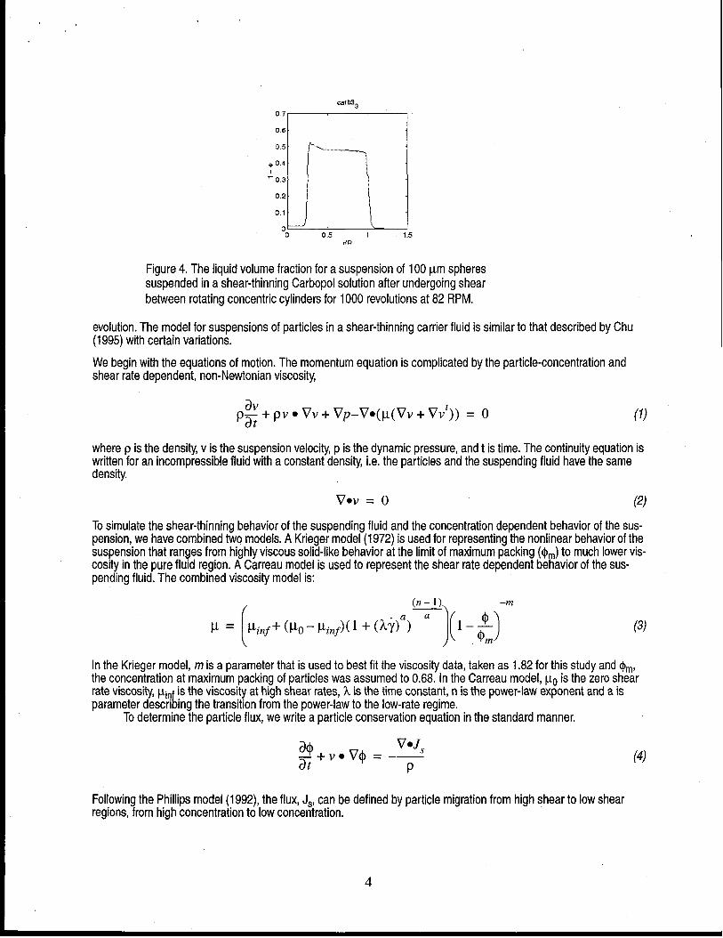
Figure 5 shows numerical results for theChu(1995) model and the one presented in this paper. The Chu (1995) modeldemonstrates a particle rich region right next to the inner cylinder and a particle depleted region at 0.45 r/R.
1
0.9
0.8
0.7
0.6
.-
; 0.5
0.4
0,3
0.2
0.1
0
a)
u U,$ 1
rtR
1
b)0.9 -
0.8
0.7
0.6
.-
$ 0.5
0.4
0.3
0.2 ~
0.1 I
,~o 0.5 1 1.5
r/R
Figure 5: Comparison of two forms of the diffusive flux model after 100 turns in Couette apparatus for slow rate(8:5 RPM) for 675pm spheres: a)Chu model b) Current model.
This is because the viscosity drops dramatically at the inner cylinder because of the high shear rates there. This makesthe viscosity very insensitive to particle concentration, allowing particles to migrate in from the high viscosity regionaway from the inner cylinder into the high shear rate zone adjacent to the inner cylinder. Unfortunately, experimentally
5

(see Figure 3), no particle rich region is found near the inner cylinder. The current model, represented in equation 9,does predict the correct trends when compared with experiment. There is a particle depleted region at the inner cylinderand a peak in particle concentration at about 0.5 r/R and no change in particle concentration at radius of 0,7 r/R. Sincethis model predicts the correct trends with essentially untuned parameters, it was chosen for the rest of this study
For details of the numerical method, see our companion paper in this proceedings (Mondy et al,, 1999).
Carreau Viscosity Mode/We fit the Carbopol suspending fluid data to a Carreau model using a plotting program, Templegraph, in which theparameters of the model can be varied to fit given data. Figure 6 shows the fitted Carreau viscosity function with theexperimental data for Carbopol solutions.
(n-1)
P’ = P’inf+ (P’()-Ki.f)(l+ (k’i’)”)a (9)
At the time the only available data was obtained from reading a plot; thus some error was introduced in the curve-fittingexercise. One of the difficulties that arose was the magnitude of the zero shear rate viscosity given the fact that the
experimental data only went to shear rates of O.ls-l and only included the power law regime and not the part of the vis-cosity curve that curves over to the low shear rate region. n, the power-law exponent, was taken from the slope of theexperimental results to be 0.178. a was assumed to be unity.
1e+06~
1e+02 1 11e-05 1e-04 1e-03 1e-02 1e-01 1e+OO 1e+Ol
shear rate (1/s)
6
Figure 6: Fitted Carreau viscosity (line) as a function of shear rate plottedwith the experimental data (triangles) for Carbopol solution.
The parameters for the Carreau model are given in Table 1.
.
Table 1. Parameters used for Carreau Viscosity Function
Quantity Value
zero shear rate viscosity, ILo 400000 Poise
high shear rate viscosity, ~inf 10 Poise
time constant, k 2150 S
power-law exponent, n 0.178
transition exponent, a 1.
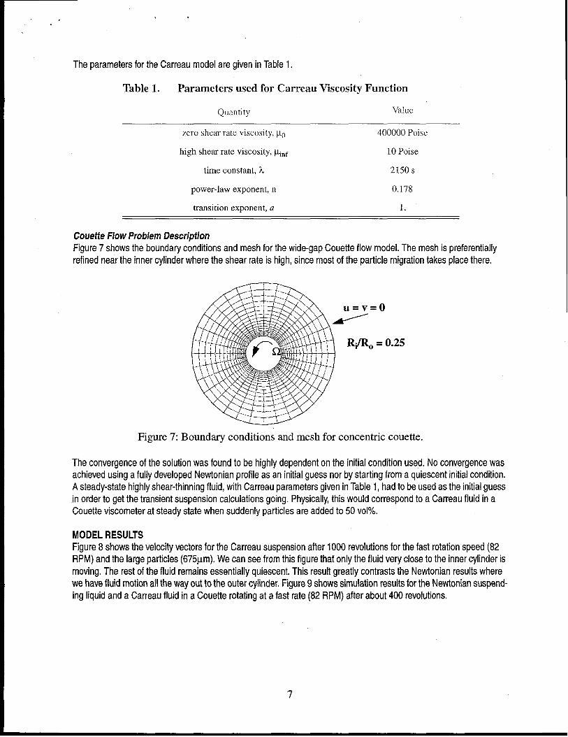
Couette FlowProblem flescriptionFigure 7 shows the boundary conditions and mesh for the wide-gap Couette flow model. The mesh is preferentiallyrefined near the inner cylinder where the shear rate is high, since most of the particle migration takes place there.
Figure 7: Boundary conditions and mesh for concentric couette.
The convergence of the solution was found to be highly dependent on the initial condition used. No convergence wasachieved using a fully developed Newtonian profile as an initial guess nor by starting from a quiescent initial condition.A steady-state highly shear-thinning fluid, with Carreau parameters given in Table 1, had to be used as the initial guessin order to get the transient suspension calculations going. Physically, this would correspond to a Carreau fluid in aCouette viscometer at steady state when suddenly particles are added to 50 VOI%.
7
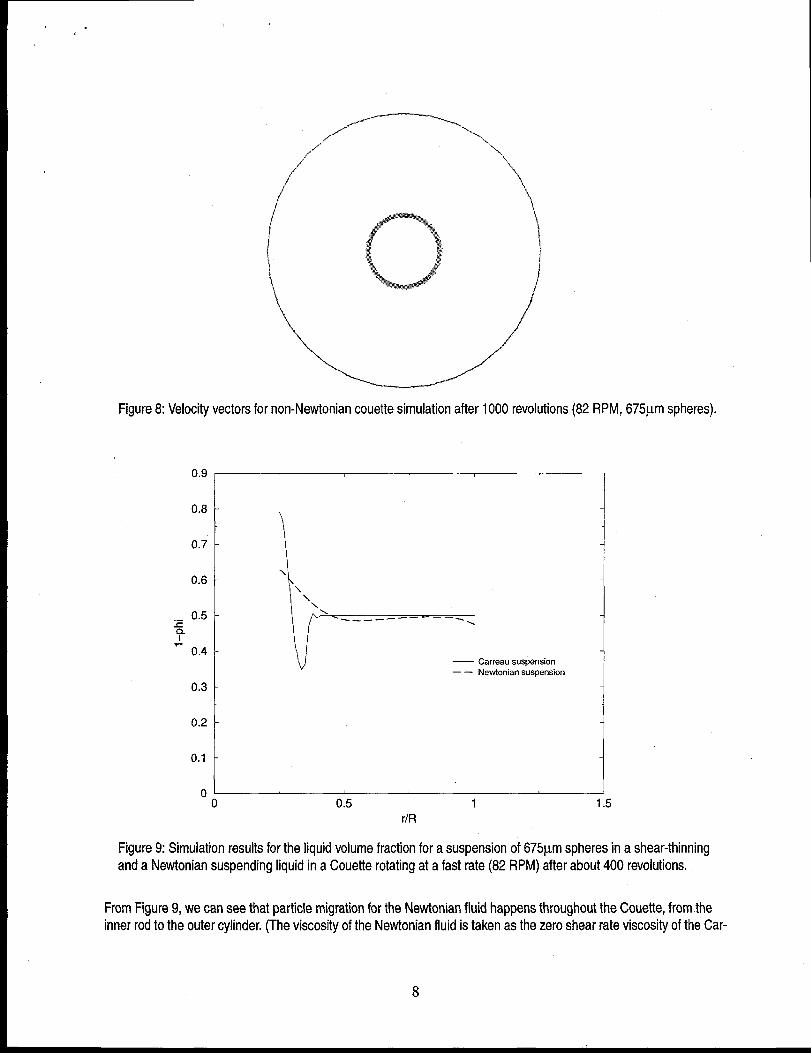
MODELRESULTSFigure 8 shows the velocity vectors for the Carreau suspension after 1000 revolutions for the fast rotation speed (82RPM) and the large particles (675~m). We can see from this figure that only the fluid very close to the inner cylinder ismoving. The rest of the fluid remains essentially quiescent. This result greatly contrasts the Newtonian results wherewe have fluid motion all the way out to the outer cylinder. Figure 9 shows simulation results for the Newtonian suspend-ing liquid and a Carreau fluid in a Couette rotating at a fast rate (82 RPM) after about 400 revolutions.
.
Figure 8: Velocity vectors for non-Newtonian couette simulation after 1000 revolutions (82 RPM, 675pm spheres).
‘“8I \0.7 -
0.6 -\
\\
\._ 0.5 - \
.—— —- ————— .=cy
“_ 0.4 -— Carreau suspension
—— Newtonian suspension
0.3 -
0.2
0.11
01 , I
o 0.5 1 1.5
r/R
Figure 9: Simulation results for the liquid volume fraction for a suspension of 675pm spheres in a shear-thinningand a Newtonian suspending liquid in a Couette rotating at a fast rate (82 RPM) after about 400 revolutions.
From Figure 9, we can see that particle migration for the Newtonian fluid happens throughout the Couette, from theinner rod to the outer cylinder. (The viscosity of the Newtonian fluid is taken as the zero shear rate viscosity of the Car-
8

..
a
reau fluid from Table 1.) In contrast, the particles suspended in the Carreau fluid exhibit particle migration only ciose tothe inner cylinder,
This result can be explained by the high zero shear rate viscosity used for the model and the small high shearrate viscosity. Figure 10 is a plot of the shear rate after approximately 400 revolutions for the large particles (675~m) atthe fast rotation rate (82 RPM). From this figure, we can see that the shear rate is highest near the inner cylinder anddecays to near zero at the outer cylinder. This means that the suspending fluid viscosity will span almost the entirerange shown on the plot of the Carreau model, Figure 6. So we get a suspending fluid viscosity of 100 Poise or lessnear the inner cylinder with the viscosity growing to 400,000 Poise by about 0.6 r/R,
‘e+”’~1e+02 11e+Ol
1
1e-03 11e-04 ~
— 82 RPM
--- 8.5 RPM\\1
\
\
\
\
1
I
1
\
\
!
I
I
\
1
\
\
!
\
\
I
1
\ ,.v . .
-..
---. .
--
-------.
1e-05 t 1 I t0.0 0.5 1.0 1.5 ‘
r/R
Figure 10: Shear rate as a function of dimensionless radius in Couette after about 400 turns.
The evolution of the suspending liquid volume fraction for the large particles in the Couette rotating at the slow rate canbe seen in Figure 11. Figure 11 can be compared to the experimental results for the same parameters that are given inFigure 2. We can seethe correct trends are obtained from the simulation. Particles near the inner rod migrate awayquite quickly leaving a fluid rich region. The peak in particle concentration occurs at about 0.4 r/R, which is close to theexperimentally obtained result of 0.45, Also the suspension remains at a constant concentration past an r/R of 0,5,which is a slightly lower result than the experimental value of 0.6. Qualitatively, the trends are correct for the modelingresults, but quantitative differences remain. The high suspending fluid concentration peak is much larger in the simula-tion, on the order of 0.8, compared to 0.6 in the experiments. Also, the maximum particle concentration in the simula-tion is on the order of maximum packing (0.68), whereas in the experiments the maximum value is closer to 0,55.
Figure 12 is the analogous plot for the large particles in the Couette turning at a fast rate. Figure 12 can be com-pared to the experimental results for the same parameters that are given in Figure 3. We have the same agreement intrends that we saw for the slow rate, with again the lack of quantitative agreement with the experimental results. Someof the trends we see going from the low rate to the high rate experimentally, such as a high peak in the liquid volumefraction are seen in going from the low rate to the high rate in the numerical simulations. The simulations do not, how-ever, predict a larger zone of influence for the fast rotation rate compared to the slow rate. In fact, the numerical resultspredict the opposite results from the experiments for the zone of influence.
9

,.
0.9
0.8
0.7
r
0.6 -
,_ 0.5 --cy
- 0.4 -
0.3 -
0.2
0.1
I
)‘J
--- 406 revolutions—— 1633 revolutions
“o 0.5 1 1.5r/R
Figure 11: Simulation results for the evolution of liquid volume fraction for a suspension of 675pm spheres in Car-bopoi solution in Couette rotating at a slow rate (8.5 RPM).
0.9
0.8
0.7
0.6
,_ 0.5cy
- 0.4
0.3
0.2
0.1
\‘),\
‘:1II{1II
— 41 revolutions––– 417 revolutions—— 1600 revolutions
io~o 0.5 1 1.5
rlR
Figure 12 Simulation results for the evolution of liquid volume fraction for a suspension of 675pm spheres in Car-bopol solution in Couette rotating at a fast rate (82 RPM).
10

Figure 13 is the analogous plot for the small particles (1OOpm) in the Couette turning at a fast rate. Figure 13can be compared to the experimental results for the same parameters that is given in Figure 4. Again, the simulationresults are giving the correct qualitative behavior. Less migration has taken place for the small particles compared tothe large particles (compare Figure 12 and Figure 13). Also, the highest suspending liquid volume fraction is smallerfor the small particles and the peak in particle concentration is smaller and closer to the inner cylinder. But the model-ing results are again much more dramatic than the experimental measurements.
0.9
0.8
0.7
0.6
0.5zy
- 0.4
0.3
0.2
0.1
0
1
\i
o 0.5 1 1.5r/R
Figure 13: Simulation results for the liquid volume fraction for a suspension of 100pm spheres in Carbopol solu-tion in Couette rotating at a fast rate (82 RPM) after 1,000 turns.
The discrepancy between the modeling results and the experiment can be explained with several rationales.First, the simulation results, especially the shape of the concentration curves was very sensitive to the parametersused in the Carreau model for the suspending fluid. If a lower zero shear rate viscosity was used, we found that thezone of change spread out toward the outer cylinder. To obtain a better fit between the model and the experiment, wewill need to get more theological data, especially in the low shear rate regime that is so important for the shape of theconcentration curves. The diffusion coefficients, Do and DW,used were optimized for Newtonian flow profiles and may
not be appropriate for shear-thinning flows. Also, we have discarded the term used by Chu (1995) because it did notfollow the trends we saw in the experimental data. Our model maybe more accurate if we use this term with a differentcoefficient constant in front of it from the coefficient on the concentration gradient of viscosity. If the coefficient werechosen correctly, it could decrease the peak concentration value and also spread out the concentration profiles givingus better agreement with experiment.
CONCLUSIONS
We have achieved good qualitative agreement between the simulations and the experiments. The model presentedhere demonstrates most of the trends seen in the experimental results for low rotation rates, high rotation rates and big
11

.J+ .
,p-
,
and small particles, However, quantitative discrepancies exist between the model results and the experiments. Toimprove our model prediction we plan to first obtain more theological data for the Carbopol suspending fluid, especiallyin the low shear rate region that is critical to the shape of the concentration profiles. The diffusion coefficients will alsobe optimized for shear-thinning fluids. We also plan on testing out a hybrid model combining our model with that of Chu(1995). This model will have a coefficient in front of the viscosity gradient with respect to shear rate that will allow us totune it to the experimental results.
Acknowledgments
This work was supported by the United States Department of Energy under Contract DE-AC04-94AL85000. Sandia isa multiprogram laboratory operated by Sandia Corporation, a Lockheed Martin Company, for the United StatesDepartment of Energy. The authors would like to acknowledge support for this work by the U.S. Department of Energy,Division of Engineering and Geosciences, Office of Basic Energy Sciences. Partial funding for the work done at theNaval Air Warfare Center was also provided by SDIO/lST and managed by the Office of Naval Research.
References
Abbott, J. R., Tetlow, N., Graham, A. L., Altobelli, S. A., Fukushima, E., Mondy, L. A., & Stephens, T., A., “Experimen-tal Observations of Particle Migration in Concentrated Suspensions: Couette Flow,” J. F?heo/.,35,773,1991.
Abraham, The Principles of Nuc/earMagnetkvn, Clarendon, Oxford, 1961
Bird, R, B., R. C. Armstrong, and O. Hassager, Dynamics of F’o/ymeric Liquids, Wiley, New York, New York (1987).
Chu, Y., The Finite Volume Method for Shear-Induced Particle Migration in Concentrated Suspension, Master’s Thesis,University of Sydney, 1995,
Leighton, D. and Acrivos, A., “Measurement of Shear-induced Self-diffusion in Concentrated Suspensions of Spheres,”J. F/uid Mechanics, 177,109 (1987),
Mondy, L. A., FL R. Rae, A. Sun, S. Altobelli, J. Seymour, “NMR Measurements and Finite Element Modeling of Non-Neutrally Buoyant Suspensions,” Proceedings of Rheology in the Miners/ /ndustry //, March, 1999.
Phillips, R. J., Armstrong, R. C,, Brown, R. A., Graham, A. L.& Abott, J. R., “A Constitutive Equation for ConcentratedSuspensions that Accounts for Shear-induced Particle Migration,” Phys, Fluids A, 4,30 (1992).
Tetlow, N., A,L. Graham, M, S. Ingber, S. R. Subia, L. A. Mondy and S. A. Altobelii, “Practice Migration in a CouetteApparatus: Experiment and Modeling,: J. Rheology, 42,307 (1998).
12