Embed Size (px)
Citation preview


Finite Element Modeling of the 12V power distribution within Open Rack Standard 2.0. Analysis of the losses and temperature rise.
Menno Kortekaas, CTO, Circle BSamuel Brumhard, Product Manager RittalNicola Cinagrossi, Engineering Director, Bel Power Solutions & Protection
Rack & Power
Content
Rack configurations
FEM simulation model
FEM simulation results
Conclusion

Config. 1 - Typical ORv2 Rack layout
RACK & POWER
Amount Part Number min weight max weight idle power (W) max power (W)
2 Bel Power Solutions
SPSPFE3-08 Power Shelf
NA 300 NA 18000 (5+1)
12 Bel Power Solutions
PFE3000-12-069RA
NA NA NA 3000
1 19“ switch kit 0 0 NA NA
3 2OU blank plate NA NA NA NA
16 Dummy node NA NA NA NA
16 Cubby for 3 server 224 224
16 Wiwynn SV7220G3 (330W) 110,4 116,8 1728 5280
16 Wiwynn SV7220G3 (330W) 110,4 116,8 1728 5280
Total 716,8 729,6 3486 10560
TestedConfigurations
• Typical 330W max server, as per datasheet• 3+3 3kW PSU = 9kW limit per zone• Switch not taking into account
Case Studies
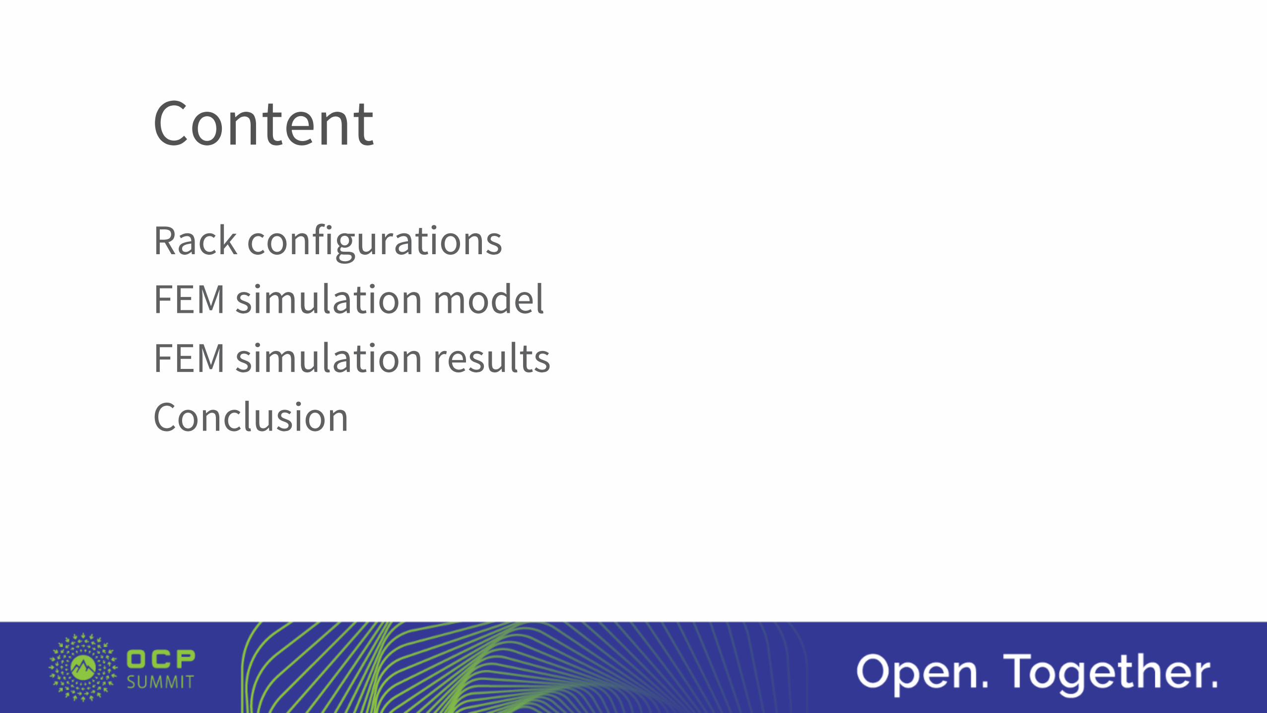
Config. 2 - Rack filled with Vendor max spec
RACK & POWER
• Typical 330W max server, as per datasheet• 3+3 3.6kW PSU = 10.8kW limit per zone• Switch not taking into account
Amount Part Number min weight max weight idle power (W) max power (W)
2 Bel Power Solutions
SPSPFE3-08 Power Shelf
NA 300 NA 18000 (5+1)
12 Bel Power Solutions
PFE3600-12-069RA
NA NA NA 3600
1 19“ switch kit 0 0 NA NA
19 Cubby for 3 server 266 266
30 Wiwynn SV7220G3 (330W) 207 219 3240 9900
27 Wiwynn SV7220G3 (330W) 186,3 197,1 2916 8910
Total 959,3 982,1 6186 18810
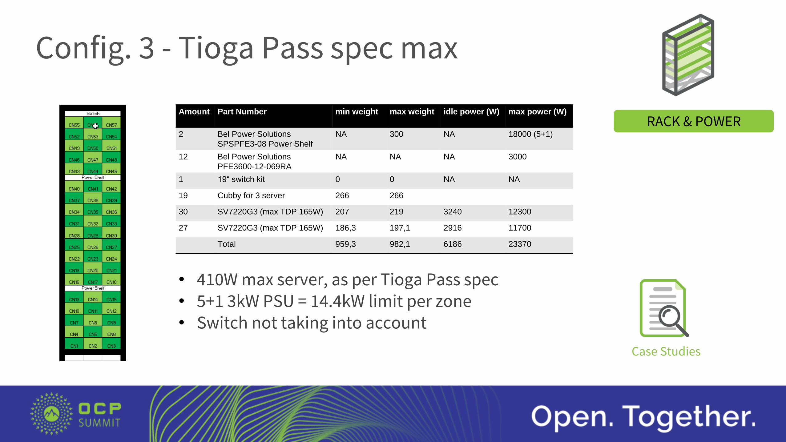
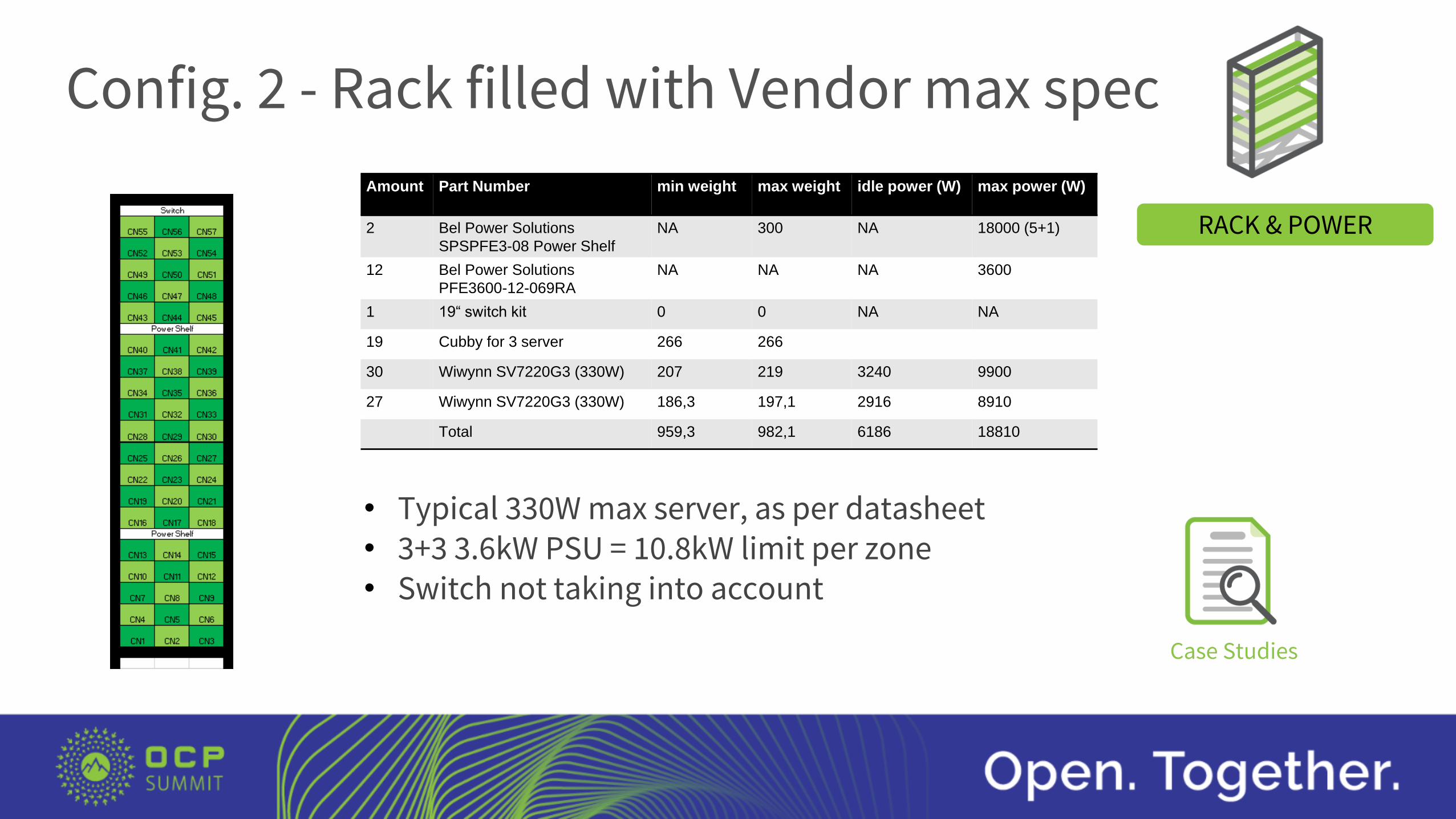
Config. 3 - Tioga Pass spec max
RACK & POWER
• 410W max server, as per Tioga Pass spec• 5+1 3kW PSU = 14.4kW limit per zone• Switch not taking into account
Case Studies
Amount Part Number min weight max weight idle power (W) max power (W)
2 Bel Power Solutions
SPSPFE3-08 Power Shelf
NA 300 NA 18000 (5+1)
12 Bel Power Solutions
PFE3600-12-069RA
NA NA NA 3000
1 19“ switch kit 0 0 NA NA
19 Cubby for 3 server 266 266
30 SV7220G3 (max TDP 165W) 207 219 3240 12300
27 SV7220G3 (max TDP 165W) 186,3 197,1 2916 11700
Total 959,3 982,1 6186 23370
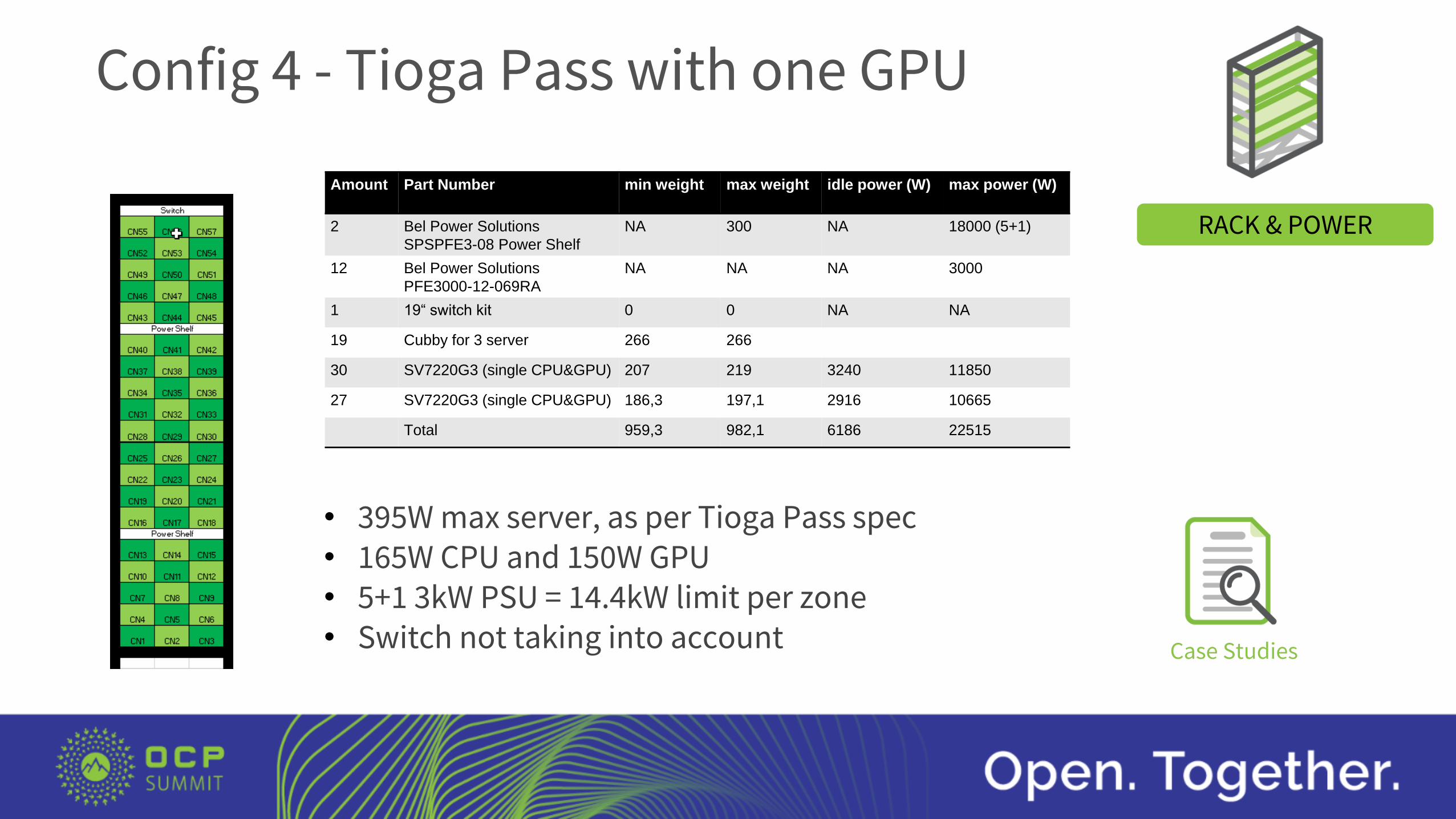
Config 4 - Tioga Pass with one GPU
RACK & POWER
• 395W max server, as per Tioga Pass spec• 165W CPU and 150W GPU• 5+1 3kW PSU = 14.4kW limit per zone• Switch not taking into account Case Studies
Amount Part Number min weight max weight idle power (W) max power (W)
2 Bel Power Solutions
SPSPFE3-08 Power Shelf
NA 300 NA 18000 (5+1)
12 Bel Power Solutions
PFE3000-12-069RA
NA NA NA 3000
1 19“ switch kit 0 0 NA NA
19 Cubby for 3 server 266 266
30 SV7220G3 (single CPU&GPU) 207 219 3240 11850
27 SV7220G3 (single CPU&GPU) 186,3 197,1 2916 10665
Total 959,3 982,1 6186 22515

Config. 5 - Highest TDP Available
RACK & POWER
Case Studies
• 490W max server, in theory• 5+1 3.6kW PSU = 18kW limit per zone• Switch not taking into account
Amount Part Number min weight max weight idle power (W) max power (W)
2 Bel Power Solutions
SPSPFE3-08 Power Shelf
NA 300 NA 18000 (5+1)
12 Bel Power Solutions
PFE3600-12-069RA
NA NA NA 3600
1 19“ switch kit 0 0 NA NA
19 Cubby for 3 server 266 266
30 SV7220G3 (TDP 205W) 207 219 3240 14700
27 SV7220G3 (TDP 205W) 186,3 197,1 2916 13230
total 959,3 982,1 6186 27930
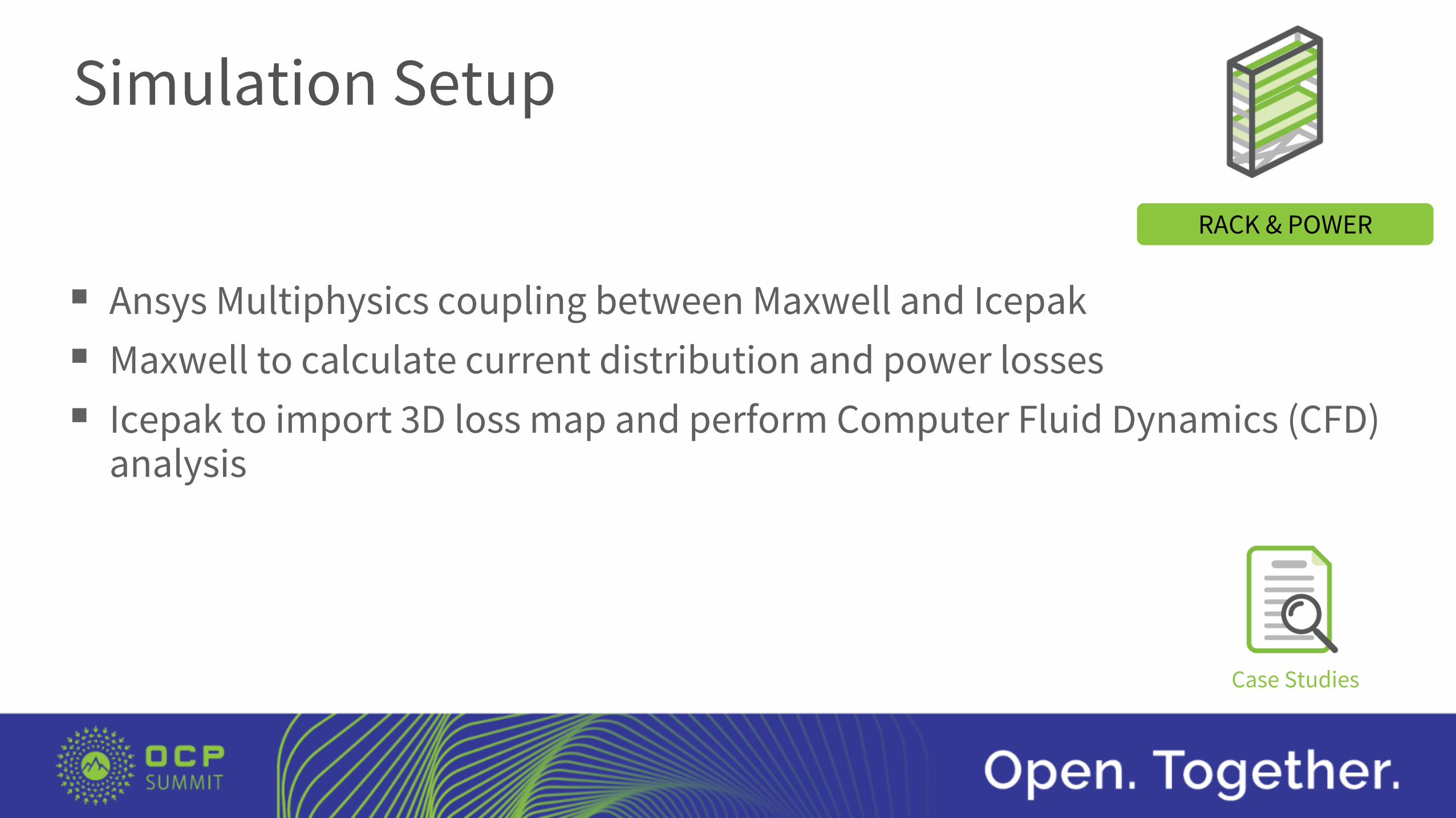
Simulation Setup
Ansys Multiphysics coupling between Maxwell and Icepak
Maxwell to calculate current distribution and power losses
Icepak to import 3D loss map and perform Computer Fluid Dynamics (CFD) analysis
RACK & POWER
Case Studies

Simulation Setup – Airflow & Mesh
Aiflow per server = 30L/s (max capability 60L/s) Airflow per power zone = 900L/s (30 servers) Aiflow speed in power zone = 3.6m/s Airflow in power shelf = 38L/s Aiflow speed in power shelf = 1.7m/s
CAD detailed Mesh - precise fits the CAD geometry Simplications implemented to avoid mesh crowding
in areas out of interest
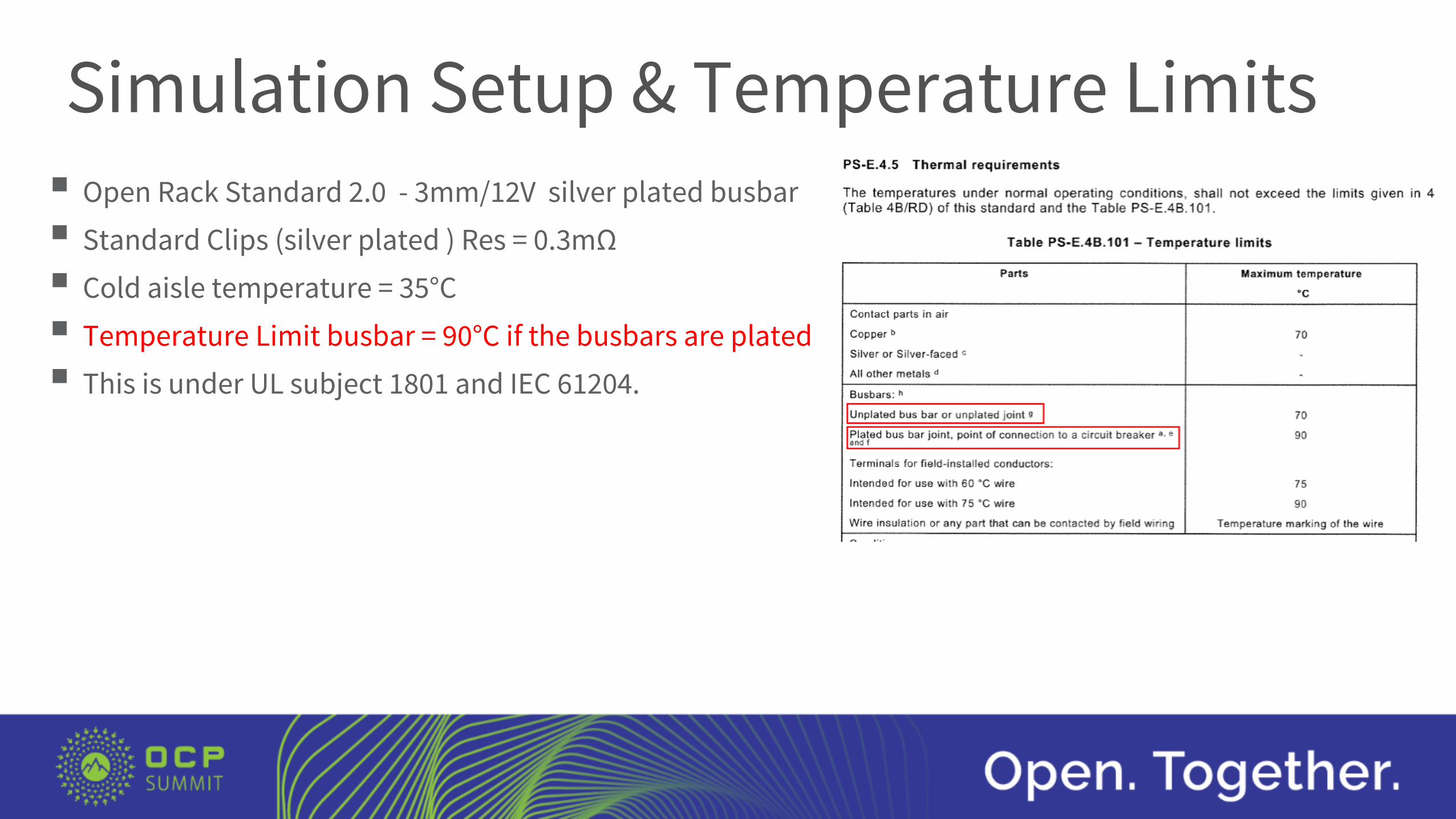
Open Rack Standard 2.0 - 3mm/12V silver plated busbar
Standard Clips (silver plated ) Res = 0.3mΩ
Cold aisle temperature = 35°C
Temperature Limit busbar = 90°C if the busbars are plated.
This is under UL subject 1801 and IEC 61204.
Simulation Setup & Temperature Limits

Simulation results Config 3 - 23.4 kW Rack
TBD Load zone 1 = 30*410W
Load zone 2 = 27*410W
Total Power delivered = 23.4kW
Load current zone 1 = 1025A
Load current zone 2 = 922A
Bus Bars Power loss = 20.5W
Hot spot = 58°C
Power Shelf bus bars loss = 34.2W
Hot spot = 65°C
Clip losses: 2.9W/clip
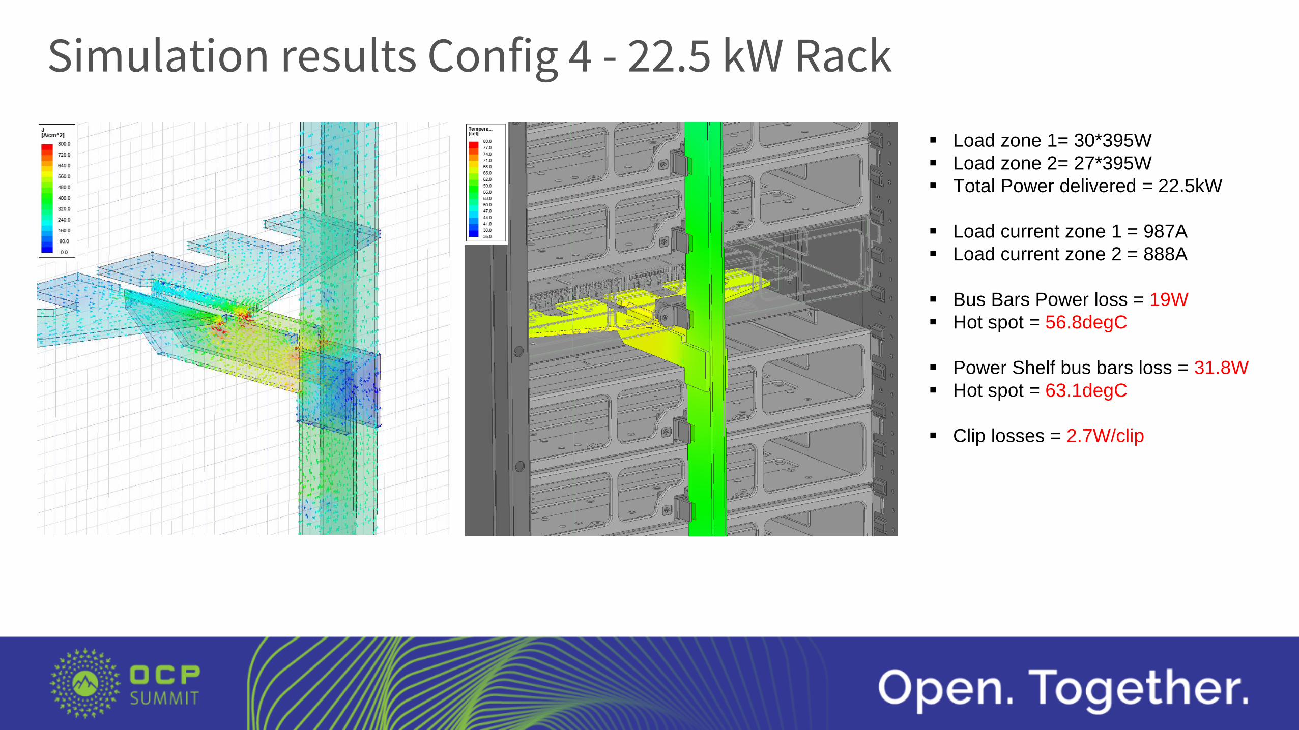
Simulation results Config 4 - 22.5 kW Rack
TBD Load zone 1= 30*395W
Load zone 2= 27*395W
Total Power delivered = 22.5kW
Load current zone 1 = 987A
Load current zone 2 = 888A
Bus Bars Power loss = 19W
Hot spot = 56.8degC
Power Shelf bus bars loss = 31.8W
Hot spot = 63.1degC
Clip losses = 2.7W/clip
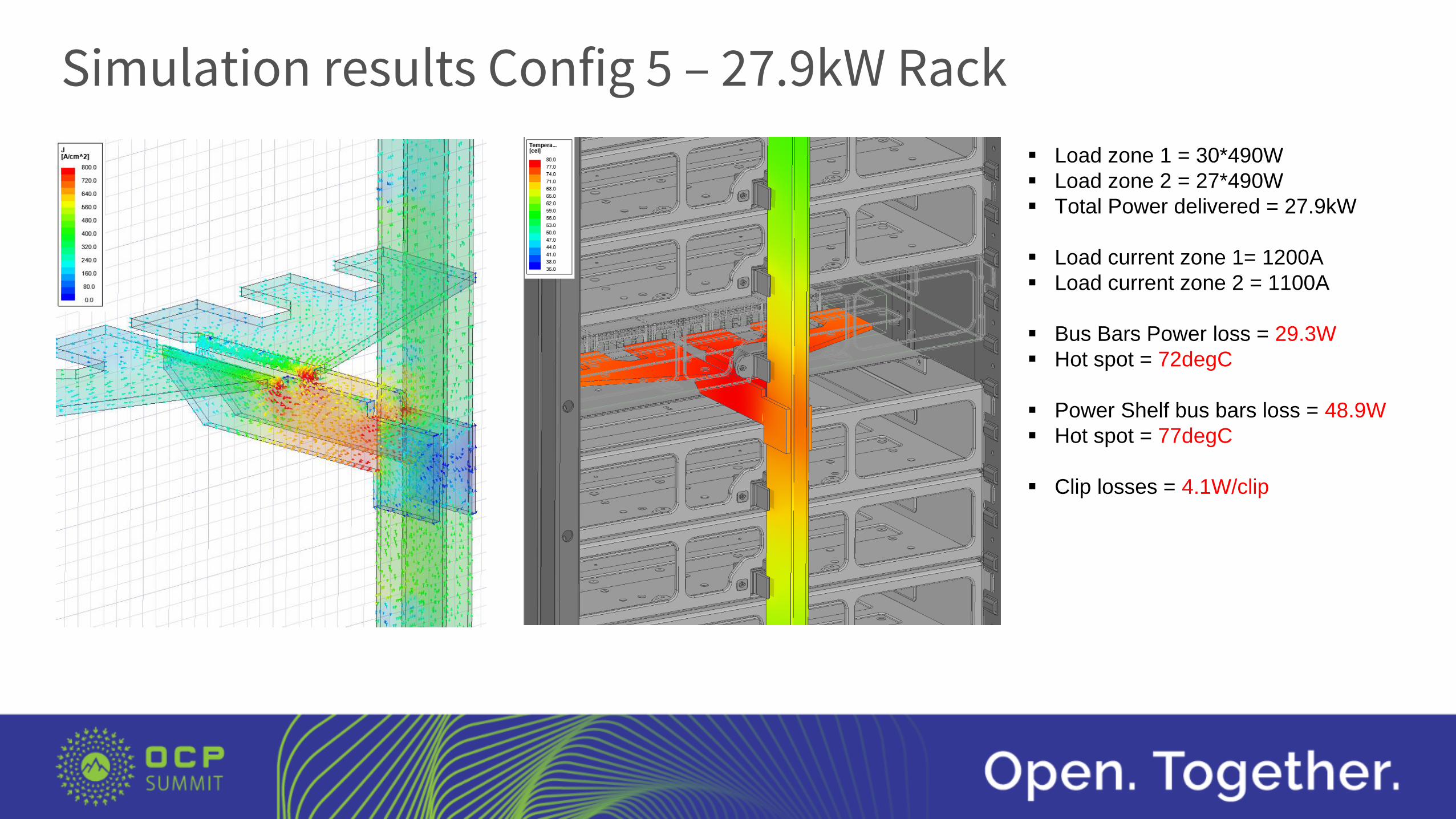
Simulation results Config 5 – 27.9kW Rack
TBD Load zone 1 = 30*490W
Load zone 2 = 27*490W
Total Power delivered = 27.9kW
Load current zone 1= 1200A
Load current zone 2 = 1100A
Bus Bars Power loss = 29.3W
Hot spot = 72degC
Power Shelf bus bars loss = 48.9W
Hot spot = 77degC
Clip losses = 4.1W/clip
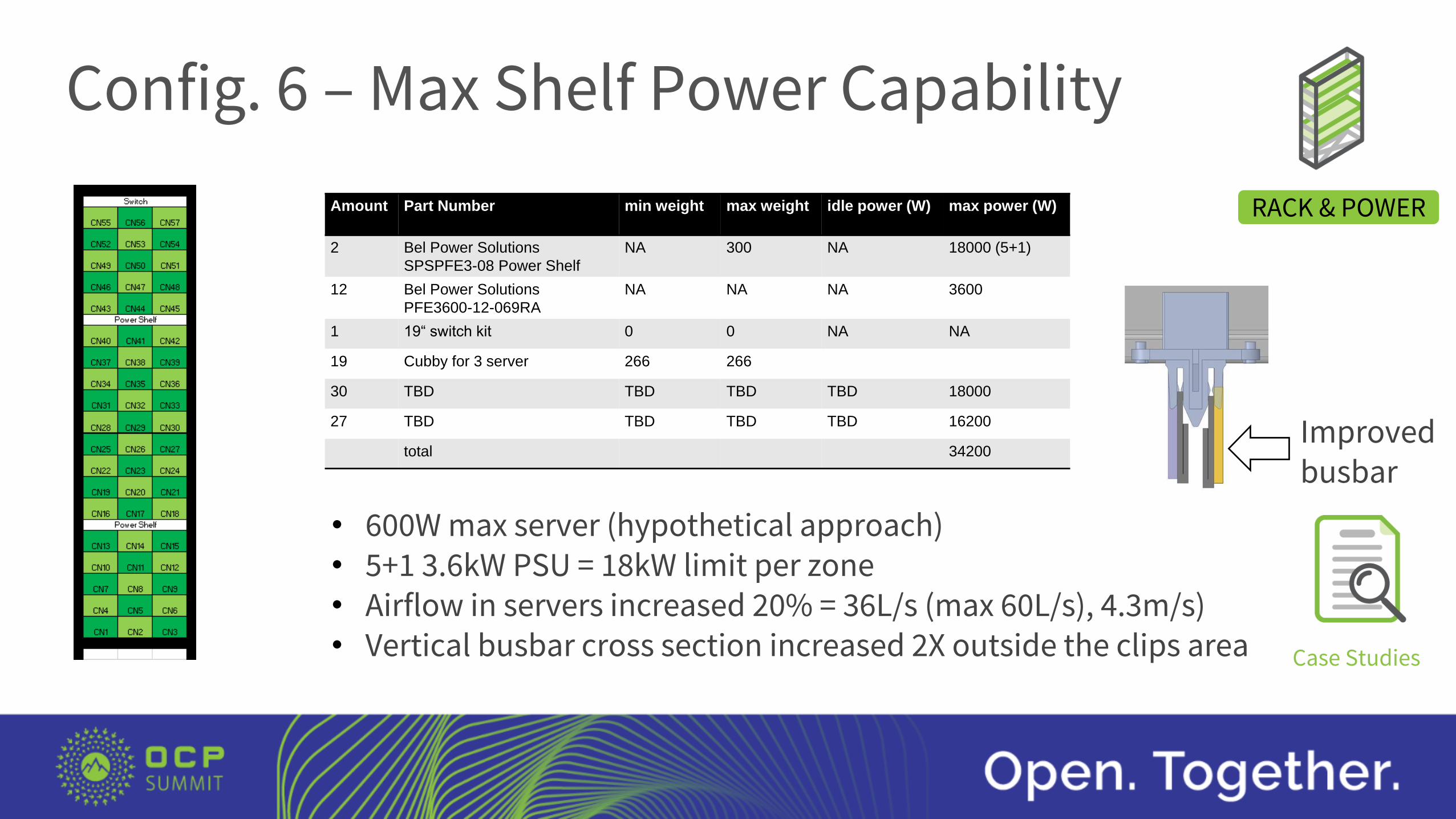
Config. 6 – Max Shelf Power Capability
RACK & POWER
Case Studies
• 600W max server (hypothetical approach)• 5+1 3.6kW PSU = 18kW limit per zone• Airflow in servers increased 20% = 36L/s (max 60L/s), 4.3m/s)• Vertical busbar cross section increased 2X outside the clips area
Amount Part Number min weight max weight idle power (W) max power (W)
2 Bel Power Solutions
SPSPFE3-08 Power Shelf
NA 300 NA 18000 (5+1)
12 Bel Power Solutions
PFE3600-12-069RA
NA NA NA 3600
1 19“ switch kit 0 0 NA NA
19 Cubby for 3 server 266 266
30 TBD TBD TBD TBD 18000
27 TBD TBD TBD TBD 16200
total 34200Improved busbar
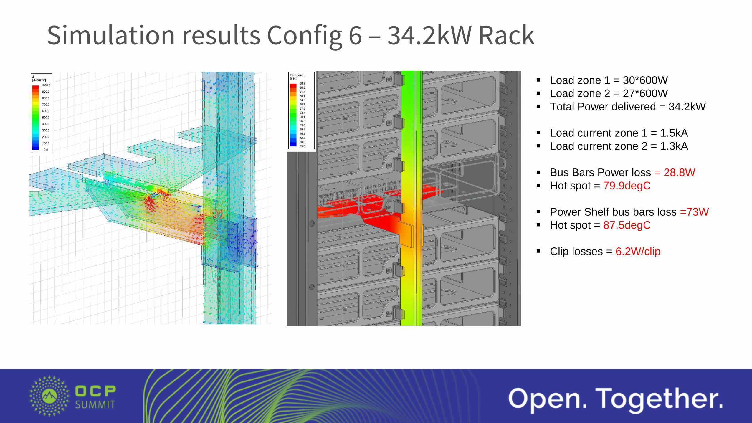
Simulation results Config 6 – 34.2kW Rack
TBD Load zone 1 = 30*600W
Load zone 2 = 27*600W
Total Power delivered = 34.2kW
Load current zone 1 = 1.5kA
Load current zone 2 = 1.3kA
Bus Bars Power loss = 28.8W
Hot spot = 79.9degC
Power Shelf bus bars loss =73W
Hot spot = 87.5degC
Clip losses = 6.2W/clip
Conclusion
FEM simulations are a key element to explore the power capability of new rack configurations
Circle B , Rittal, Bel Power Solutions can provide fully equipped racks and if required simulations to estimate in advance power losses and temperatures
The 12V power distribution of the rack and power shelf bus bars (excluding clips) of the Open Rack Standard 2.0 provided by Rittal in conjunction with the Bel Power Solutions Power Shelf (SPSPFE3 family) can cover without any HW change the configuration with the highest TDP available (27.9kW in the rack)
With a modification of the 12V vertical busbar it is possible to achieve up to 18kW on each power zone resulting to 36kW per rack.
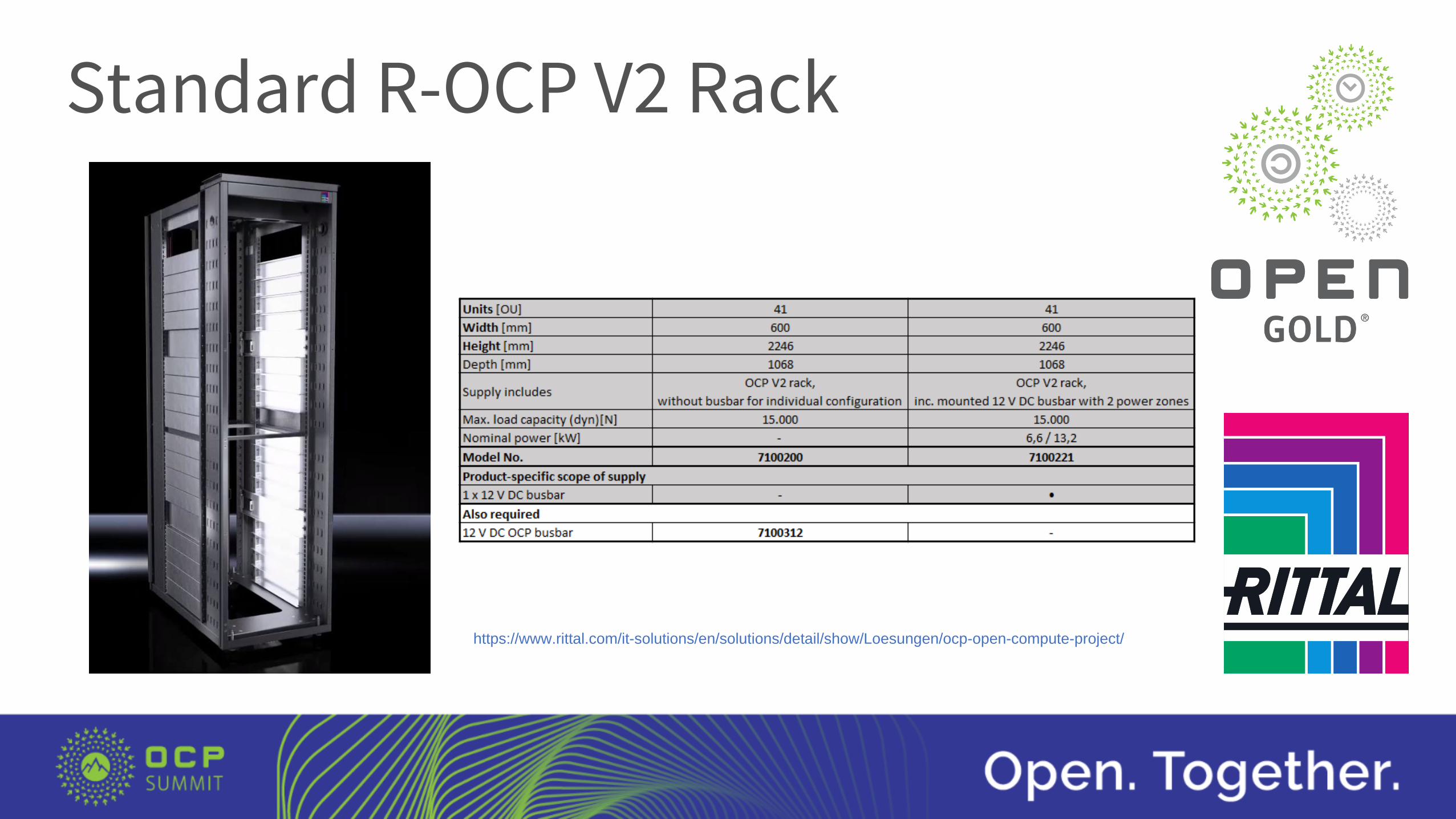
Standard R-OCP V2 Rack
https://www.rittal.com/it-solutions/en/solutions/detail/show/Loesungen/ocp-open-compute-project/

Circle B – Solution Provider in Europe
Visit our website: CircleB.eu
Or the OCP Marketplace:Open Rack v2 - AC Bundle
Wiwynn SV7220G3 Server
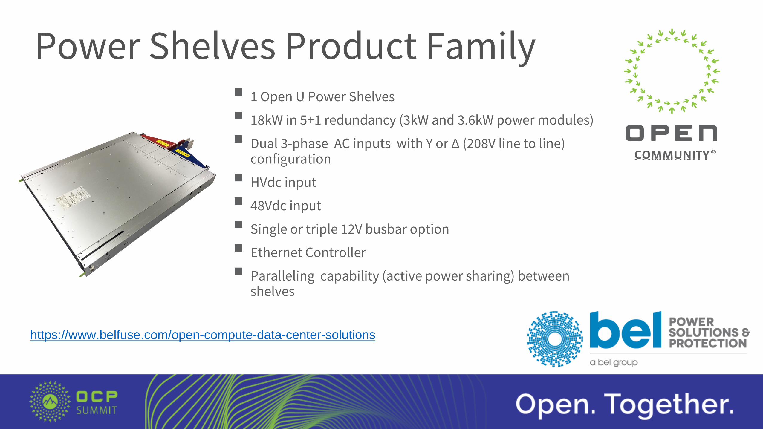
Power Shelves Product Family 1 Open U Power Shelves
18kW in 5+1 redundancy (3kW and 3.6kW power modules)
Dual 3-phase AC inputs with Y or ∆ (208V line to line) configuration
HVdc input
48Vdc input
Single or triple 12V busbar option
Ethernet Controller
Paralleling capability (active power sharing) between shelves
https://www.belfuse.com/open-compute-data-center-solutions