Embed Size (px)
Citation preview

J. Mater. Shaping Technol. (1990) 8:53-64 �9 1990 Springer-Verlag New York Inc.
Finite Element Simulation of Some Extrusion Processes Using the
Arbitrary Lagrangian-Eulerian Description
Somnath Ghosh
A b s t r a c t . This paper aims at simulating a few typical extrusion processes, using the finite element method for large deformation analysis of elastic-viscoplastic materials. An arbitrary Lagrangian-Eulerian kinematic description is implemented for enhanced accuracy and performance of the analysis. Various schemes for moving the three-dimensional com- putational grid are experimented with, for analysis up to large degrees of deformation.
I N T R O D U C T I O N
Extrusion has typically been one of the most widely used metal forming processes for manufacturing rods, tubes, cans, etc. This is because of the effectiveness of the process in yielding precise dimensions with good surface finish at a high productivity rate. In this bulk metal forming process, a billet is pushed through an opening in the work tool to yield finished products, conforming with the requirements of technology. Generally speaking, these processes may be classified into three broad categories depending on the direction of movement of the extruded parts relative to the punch. They are as follows:
1. Forward extrusion: material flows in the same di- rection as the motion of the punch.
2. Backward extrusion: material flows in a direction opposite to the motion of the punch.
3. Side extrusion: material flow is perpendicular to the direction of motion of the punch.
Analysis of extrusion processes for determination of punch pressure, stress/strain distributions, material flow patterns, etc., is of extreme importance to the manufacturing process designer for a number of rea- sons. They provide valuable information, not only for enhanced design of work tools and process parameters like velocity, lubrication, etc., to manufacture defect-
The author is with the Department of Engineering Mechanics, The University of Alabama, Tuscaloosa, AL 35487, USA.
free products of superior quality, but also for im- proving existing methods and inventing new ones.
Several approximate analytical and numerical methods for solving problems of metal forming have emerged as a result of research for more than half a century. Notable among the pioneering contributions on analytical methods are the slab or force balance methods by Sachs [1] and the work of deformation method or the uniform energy method by Siebel [2] based on oversimplified deformation patterns. The Fast slip line field analysis of extrusion in plane strain for nonhardening rigid-plastic solid was proposed by Hill [3]. Despite its shortcomings in neglecting elastic and hardening effects and confinement to plane strain problems, this technique was the cornerstone of metal forming analysis for a prolonged period of time be- cause of its simplicity and the clarity with which it reflects the major deformation mode. Another ana- lytical method that has been favored by engineers as an adequate method for approximate analysis, utilizes the upper bound theorem of limit analysis. This ap- proach was first utilized by Johnson and Kudo [4] for plane strain and axisymmetric problems and by Av- itzur for various extrusion problems [5]. Among the other methods that were classically used in metal forming analysis, are the semiexperimental, semi- theoretical visioplasticity method developed by Sha- baik [6] and the general method based on the prin- ciple of virtual work by Hill [7]. However, in spite of their novelty, there remained a certain gap at the level of realistic simulation of the deformation pro-
J. Materials Shaping Technology, Vol. 8, No. 1, 1990 �9 53

S. Ghosh �9 Lagrangian-Eulerian FEM for Extrusion
cesses using these methods. These descriptions lacked the generality of applications with respect to arbitrary shapes of worktools/workpieces, boundary condi- tions, and material properties.
The rapid growth of the computer industry from the late 1960s made it possible for sophisticated nu- merical methods like the finite element, boundary ele- ment, and finite difference methods to greatly sub- stantiate their capability for analysis of metal forming processes. Within the framework of finite element methodology, two approaches, namely the f l o w ap- proach and the solid approach emerged. The flow ap- proach, which was originally advocated by Zienkiew- icz and coworkers [8,9] and extended by Dawson and Thompson [10] among others, considers the metal to behave like a nonNewtonian viscous fluid. Typical shortcomings of this method are that it cannot rep- resent many of the subtleties of elastic-plastic con- stitutive laws, hence restricting information on resid- ual stresses and also its inability to solve directly for the displacements. Contrarily, the solid approach treats the solid as an elastic-plastic/viscoplastic material and has gained more popularity with researchers in the area of metal forming. A large volume of research based on this approach, to treat problems of metal forming using the total and updated Lagrangian descriptions, have evolved to date. Notable among them in the area of extrusion are the work by Lee, Mallet, and Yang [11], Yamada, Wifi, and Hirakawa [12], Nagtegaal and De Jong [13], and Argyris and Doltsinis [14], to name a few.
In spite of the stupendous success of the Lagran- gian method, it suffers from major drawbacks when the workpiece endures large or localized deformation and also when the worktools, namely the punch and die, have complex shapes or sharp edges. This may be attributed to the fact that, in the Lagrangian de- scription, the finite element mesh remains embedded in the material and moves with it. Lack of control over the grid motion often results in excessively dis- torted elements, thus deteriorating the quality of the finite element solutions. Continuing the simulation beyond certain levels of deformation becomes impos- sible in many cases, on account of entangled or non- convex elements. Also, in cases where the worktools, such as the punch or die, have complex shapes or sharp edges, accuracy of the boundary representation is questionable. In these cases, the limitations of the La- grangian description manifest in an effective change in the dimensions and shapes of the worktools. Var- ious remeshing schemes have attempted to surpass these obstacles [15], but have not been totally successful with respect to accuracy and have led to uneconom- ical computational efforts.
In an attempt to overcome the deficiencies men- tioned above, the present work introduces a flexible arbitrary Lagrangian-Eulerian description to metal forming simulations using the finite element method. In this description, the grid may assume any arbitrary velocity relative to the material with the potential to represent pure Lagrangian or Eulerian (stationary mesh) descriptions as limiting cases. This description has been employed by Haber [16], Liu et al. [17], and Heutink et al. [18] to execute large deformation analysis of elastic-plastic solids using explicit time integration, and by Ghosh and Kikuchi [19,20] to elastic-visco- plastic solids using implicit methods.
In this paper, the finite element method using an implicit arbitrary Lagrangian-Eulerian description, has been utilized for simulating extrusion problems. The material is characterized by a rate dependent elastic- viscoplastic constitutive model. A return mapping al- gorithm has been implemented for integration of stress rates at the constitutive level. Interaction between the worktools and workpiece has been modeled using an exterior penalty method for frictionless contact. Nu- merical experiments have been performed with typi- cal examples of extrusion problems to demonstrate the effectiveness of the computational model.
F INITE E L E M E N T M O D E L W I T H A LE D E S C R I P T I O N
The arbitrary Lagrangian-Eulerian (ALE) kinematic description introduces a reference configuration con- sisting of a set of unconstrained grid points undergo- ing arbitrary spatial motion. The motion of each point in the reference frame, identified by an invariant set of coordinates Xi, is expressed as a continuous func- tion of • and time t as:
xi = xi(xj,t) (1)
The relation between this referential and the material coordinates is established through a mapping of the latter on the former domain as:
Xi = f(xj , t) = f,-(Xt,t) (2)
where x and X represent current and material coor- dinates, respectively.
W e a k F o r m s an d Fin i te E l e m e n t A p p r o x i m a t i o n s An implicit scheme for time integration in large de- formation analysis of time dependent problems has been invoked from the standpoint of improved conditions on accuracy and numerical stability. In particular, the
54 �9 J. Materials Shaping Technology, Voi. 8, No. 1, 1990
midpoint family of algorithms, which have been noted to project good stability characteristics for nonlinear problems [21], have been implemented both at global and constitutive levels. According to the requirements of this scheme, the principle of virtual work and the weak form of the continuity equation are written, in a grid configuration that is intermediate to the ter- minal configurations within a time step, as:
ffl 0/~i ffl + p(vj - w9 ov, C,,da (,.+~) Oxj (,.+~) Ox:
= f a pGit~'d" + fr Titiid~ (3) (t.+~) (tn+~)
fo =In OWioda (4)
where the configuration ~(t ,+,) corresponds to an in- termediate time t,+~ and is represented as a convex combination of the positions at the beginning and end of the time step as:
x "+~ = (1 - a)x" + o.e '+1 (5)
for 0 --< a --< 1. In Eqs. (3) and (4) p is the density, o- is the Cauchy stress tensor, V is the material ve- locity, W is the grid velocity, G is the body force per unit mass, and T is the surface traction evaluated in the intermediate configuration. The momentum and mass convection terms in Eqs. (3) and (4) form the essential difference between the ALE and pure La- grangian descriptions. It should also be emphasized that the solution of the continuity equation (4) for cal- culation of the pointwise densities is necessary in the ALE formulation because of the convection of mass across element boundaries. The transient inertial term [p(OVi/Ot)[x] in the momentum balance equation has been neglected in Eq. (3), thus assuming a quasistatic process with respect to a grid point. In order to es- tablish an unambiguous connection between the re- ferential and the Lagrangian systems, an additional condit ion that the grid domain never leaves the boundary of the material has been imposed in the form:
( V - W ) . n = 0 (6)
where n is the outward normal to the solid boundary. This implies that the grid can only possesses a tan- gential relative velocity at the boundary. Detailed de- rivations of Eqs. (3) and (4) may be found in refs. [19] and [20].
S. Ghosh �9 Lagrangian-Eulerian FEM for Extrusion
Cons t i tu t ive R e l a t i o n s The material characteristics of the workpiece in ex- trusion simulation is described, using an elastic-vis- coplastic model for finite deformation, in a rotated Lagrangian system. From the requirements of objec- tivity of the constitutive equations in large deforma- tion, a relation is established between the material time derivative of the rotated Cauchy stress tensor, (t = Rr~rR, where R is obtained through the polar decom- position of the deformation gradient tensor F) , and its conjugate rate of deformation tensor d. Based on the rate form of the elasticity relation, the constitutive equation is expressed as:
] = E: d e (7)
where E is a fourth order elasticity tensor, i is the rate of rotated stress, and d e is the elastic deformation rate obtained by an additive decomposition of the rate of rotated deformation d into elastic and viscoplastic parts. An overstress model, representing the unified theories of viscoplasticity is used (see ref. [22]) to characterize the viscoplastic deformation rate:
Of d,~ p = ~ < ~[ i - K(%,0)] > - -
Otij (8)
where ~/is a temperature dependent viscosity coeffi- cient, ( . . . ) is the MacCaulay operator, K is an internal state variable such as hardening, which is a function of the inelastic work Wp and the absolute temperature 0, and F is an invariant of the rotated stress. The func- tion dp may assume any form, depending on the char- acteristics of the material being modeled. The internal state variable K used in this computation is confined to represent isotopic hardening only. A linear growth law is assumed to yield the evolution of the internal variable as:
OK _ = ~dVp (9) Ot
in which Ep is an equivalent plastic modulus and a vp is the equivalent rate of viscoplastic deformation.
B o u n d a r y C o n d i t i o n s The boundary of the domain is assumed to be entirely constituted of displacement, traction, and contact type boundaries, that is, F(t) is Fiu(t) U Fir(t) LJ Fic for 1 -< i -< 3. The contact boundary is modeled using the exterior penalty method for unilateral frictionless con- tact, which may be suitable for well lubricated tool- material interfaces. Based on the development of uni- lateral contact conditions in [23,24] the linearized
J. Materials Shaping Technology, Voi. 8, No. 1, 1990 �9 55
S. Ghosh �9 Lagrangian-Eulerian FEM for Extrusion
nonpenetration condition in the incremental analysis can be expressed as:
aAu- n "+~ - g -< 0 (10)
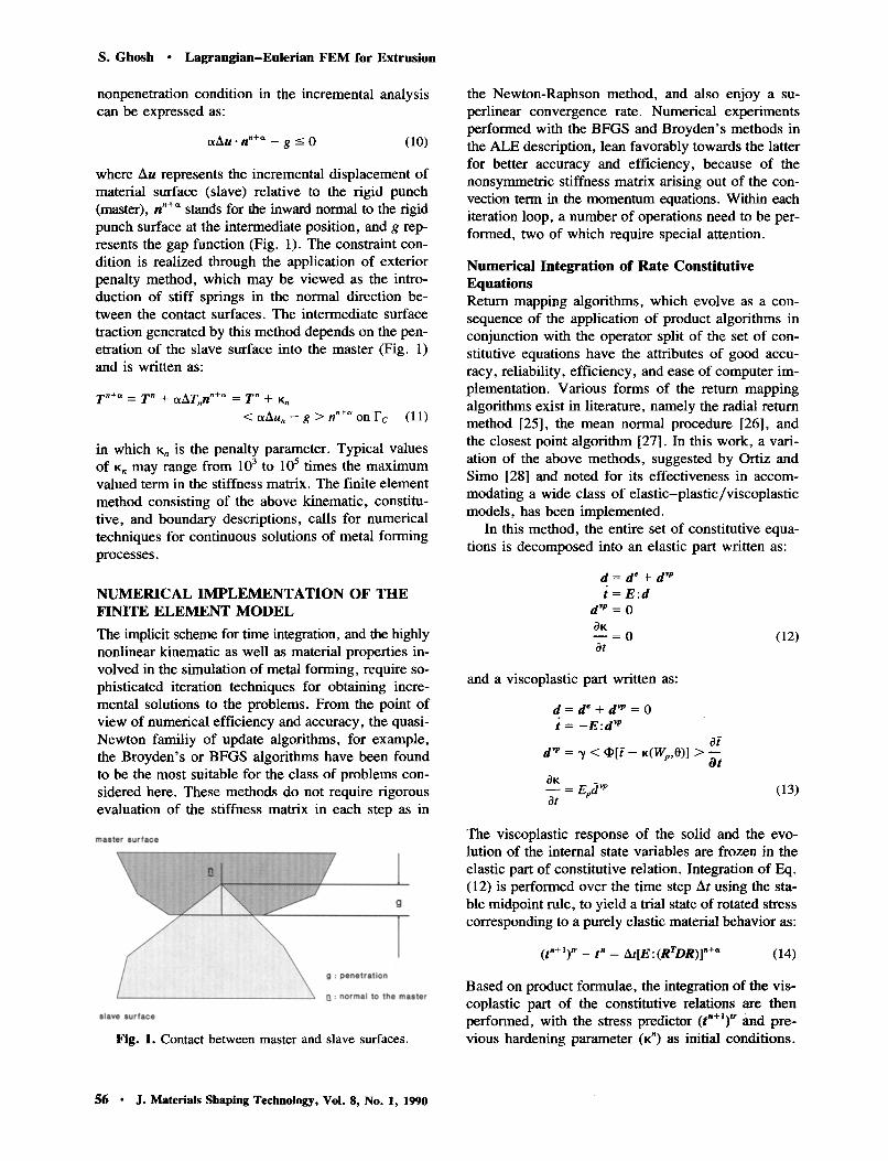
where Au represents the incremental displacement of material surface (slave) relative to the rigid punch (master), n "+~ stands for the inward normal to the rigid punch surface at the intermediate position, and g rep- resents the gap function (Fig. 1). The constraint con- dition is realized through the application of exterior penalty method, which may be viewed as the intro- duction of stiff springs in the normal direction be- tween the contact surfaces. The intermediate surface traction generated by this method depends on the pen- etration of the slave surface into the master (Fig. 1) and is written as:
T "+" = T " + a A T , , n "+~' = T " + Kn
< a A u , , - g > n "+~' o n F c (11)
in which K, is the penalty parameter. Typical values of K, may range from 10 3 t o 10 5 times the maximum valued term in the stiffness matrix. The finite element method consisting of the above kinematic, constitu- five, and boundary descriptions, calls for numerical techniques for continuous solutions of metal forming processes.
N U M E R I C A L I M P L E M E N T A T I O N OF T H E F I N I T E E L E M E N T M O D E L
The implicit scheme for time integration, and the highly nonlinear kinematic as well as material properties in- volved in the simulation of metal forming, require so- phisticated iteration techniques for obtaining incre- mental solutions to the problems. From the point of view of numerical efficiency and accuracy, the quasi- Newton familiy of update algorithms, for example, the Broyden's or BFGS algorithms have been found to be the most suitable for the class of problems con- sidered here. These methods do not require rigorous evaluation of the stiffness matrix in each step as in
Fig. 1. Contact between master and slave surfaces.
the Newton-Raphson method, and also enjoy a su- perlinear convergence rate. Numerical experiments performed with the BFGS and Broyden's methods in the ALE description, lean favorably towards the latter for better accuracy and efficiency, because of the nonsymmetric stiffness matrix arising out of the con- vection term in the momentum equations. Within each iteration loop, a number of operations need to be per- formed, two of which require special attention.
N u m e r i c a l In tegrat ion o f Rate C o n s t i t u t i v e Equat ions Return mapping algorithms, which evolve as a con- sequence of the application of product algorithms in conjunction with the operator split of the set of con- stitutive equations have the attributes of good accu- racy, reliability, efficiency, and ease of computer im- plementation. Various forms of the return mapping algorithms exist in literature, namely the radial return method [25], the mean normal procedure [26], and the closest point algorithm [27]. In this work, a vari- ation of the above methods, suggested by Ortiz and Simo [28] and noted for its effectiveness in accom- modating a wide class of elastic-plastic/viscoplastic models, has been implemented.
In this method, the entire set of constitutive equa- tions is decomposed into an elastic part written as:
d = d e + d "p
t = E : d
d "p = 0
OK - - ~ 0 ot
(12)
and a viscoplastic part written as:
d = d" + d vp = 0 t = - E : d vp
Of d "~ = ~t < ~ [ i - K(Wp,0)] > - -
fit OK
ot (13)
The viscoplastic response of the solid and the evo- lution of the internal state variables are frozen in the elastic part of constitutive relation. Integration of Eq. (12) is performed over the time step At using the sta- ble midpoint rule, to yield a trial state of rotated stress corresponding to a purely elastic material behavior as:
( t ' + l ) tr - t " = A t [ E : ( R r D R ) ] n+~ (14)
Based on product formulae, the integration of the vis- coplastic part of the constitutive relations are then performed, with the stress predictor (tn§ ~" and pre- vious hardening parameter (~") as initial conditions.
56 �9 J. Materials Shaping Technology, Vol. 8, No. 1, 1990

S. Ghosh �9 L a g r a n g i a n - E u l e r i a n F E M for Extrus ion
The overall deformation of the material is unchanged in this phase. This algorithm evaluates the final stresses corresponding to an updated loading surface, in a se- quence of projections within subintervals of the time increment. Analytically the steps to the execution of the relaxation phase may be summarized as:
Oi (to)t~ ~ = (te)~ '+1 - A e l E i j k l ( 1 - - e - (At l / , I ) ) _
Otkl xn+ I K)t+l = (K)7 += + A~,Ee(1 - e -(a'/'))
(15)
where
1 1) oi oi - - - - + E p TP Eiykt Olij Otu
is an instantaneous relaxation time in the Ith subin- terval Att, and
A~, = ~,,-,(i- K)'I7 §
In this work, the function q~(F) has been assumed to take an exponential form F p, which is suitable for most metals. It should be emphasized in this context, that the existence of the term (1 - e -(~'/~')) restricts ar- bitrary selection of subintervals within the time step, depending on the precision level of the computers used. If the term AtJ,rz is reasonably big (~10), the term 1 - e -(z'/'>) tends to 1, resulting in a collapse of the algorithm. A careful choice of Atz should therefore precede the implementation of this algorithm.
U p d a t i n g o f M a t e r i a l V a r i a b l e s to G r i d P o i n t s During large deformation analysis of time and history dependent materials, the distinction between the ma- terial and grid points invoked in the arbitrary Lagran- gian-Eulerian description calls for a special updating procedure in each time increment. Such a procedure would assign values of material variables to a partic- ular grid point at a given instant, based on the location of the grid with respect to the material. It is therefore evident that a relation between the material and re- ferential time derivatives of the material variables should be established. This is written as:
ol31 ol3 o~
to-- t = or-- + (w~ - v~) - - OXk X X
(16)
where 13(X,t) is any time dependent material variable, such as density, material velocity, Cauchy stress, hardening parameter , etc. Implicit integration of equation (16) over the time step At, yields:
O~ n+a
Ag[3 A=[~+ At(W~k § +" (17)
where Ag13 and Am13 a l e increments at a fixed grid and material point, respectively.
In order to evaluate the material increments Am13 of the variables, it is necessary to design a mapping scheme between grid and material domains in the ~ , and f~,+~ configurations. This may proceed as follows (see Fig. 2):
�9 Construct pseudo material domains at time t,+~, by projecting material displacements (otAmu) from nodal points at time t,.
�9 Using isoparametric transformation, establish the location of the grid point in local coordinates (r,s,t) within a pseudo-material element and find the in- cremental material displacement ctAmu * using: ctAmu * = otAmujV~ where N~ are the shape functions in r, s, and t.
�9 Project back onto the appropriate element in the l~,th configuration, evaluate the local coordinates within the element, and obtain the corresponding variables 13" using isoparametric interpolation.
�9 Use Eq. (17) to calculate the grid increments from the material increments and the gradients.
Other details of numerical implementation and the flow chart of the entire algorithm are given in refs. [ 19,20].
N U MERICA L EX A MP LES
Results of numerical simulation of side, backward, and forward solid extrusion processes, using the finite element program (LAGEUL) developed, are pre- sented in this paper. The analysis has been carried out in three dimensions using eight-node brick elements. The value of oL for the intermediate configuration has been set to 0.5 for accuracy and stability. The elastic- viscoplastic material being modeled is taken to be an aluminium alloy with the following properties:
L
//" t i m e t n ~ i L: Legrangian point �9 '~ ......... ALE: Lagrangian-Eulerian point , / ~ ~ L
" * i . . . . . . . . i peeudo material element
.......................... '. o Z 2 ' 2 L
L
Fig. 2. Updating of material variables in a time step.
J. Materials Shaping Technology, Vol. 8, No. 1, 1990 �9 57

S. Ghosh �9 L a g r a n g i a n - E u l e r i a n F E M for Extrus ion
Young's modulus (E) = 10 • 10 6 psi Poisson ratio (v) = 0.03 Yield stress (crr) = 0.16 • 105 psi Elastic-plastic tangent modulus (E,) = 0.230769
X 107 psi Viscosity parameter 0/) = 0.001 sec -1
The value of the exponent p for the function F v in the viscoplastic model is set to 1. Frictionless contact is assumed between the workpiece and the worktools.
S i d e E x t r u s i o n A section view of the side extrusion model is shown in Figure 3. In this process a rigid frictionless punch AC with a prescribed velocity 10 in. /sec is extruding the material through a slit BE in the die. The edges B and E of the slit in this example, pose difficulty in boundary representation with the Lagrangian descrip- tion, due to the fact that these points are fixed in space. Kinematically speaking, the nodes on these edges should be treated as Eulerian, that is, stationary points. Additionally, because of the sharp change in the di- rection of velocity of the extrudate around these points, the elements in their neighborhood have a tendency to become excessively distorted. This prevents the nu- merical simulation from progressing beyond a few time steps into the process. It is therefore obvious that the ALE description, with a judicious mesh moving scheme, is indispensable for this analysis. The side extrusion considered here has been executed for a pe- riod of 0.2 sec, corresponding to a 40% reduction of
Fig. 3. Section view of side extrusion.
height of the extrudate inside the container. The sim- ulation is carried out in 20 equal time steps. Only the upper half of the solid is modeled from symmetry considerations. The nodes lying on the edge B are made Eulerian, and displacement boundary condi- tions are imposed on them. If all the other nodes are made Eulerian, then the proximity of Lagrangian and Eulerian nodes in the neighborhood of the edge B pro- duce severely distorted and ill-conditioned elements in that region. On the other hand, as deformation pro- gresses, the elements that have moved out of the opening possess very high aspect ratios, thus yielding unreasonable results in interpolation. The effective node movements resulting from these observations can be summarized as follows:
For 0 -20% reduction in height: Hold a set of nodes, Eulerian at B. Move the set of ALE nodes above the edge B with a prescribed velocity, so that they replace the above Eulerian nodes after 20% reduc- tion (see Fig. 4). The nodes above and below dotted lines in Figure 4 are Lagrangian. Transition ALE nodes, forming a cushion between the Lagrangian and Eulerian nodes, are created within the dotted lines, which move according to a weighted aver- aging scheme:
W~+ 1 _- 1 ~jwfl~j (18)
where wj represents a weighting function associated with a Jth node that surrounds the Ith node.
For 20-40% reduction in height: Make the initial set of Eulerian nodes, Lagrangian in this phase so that they follow the material. The set of ALE nodes above them are now made Eulerian to represent the edge of the orifice. Transition nodes are moved with the averaging scheme.
As seen from Figures 4, 5, and 6, the analysis was successfully completed. Figure 4 depicts the motion of the computational grid while Figure 5 represents the corresponding material movement. The sudden opening in the wall introduces some instabilities which are visible from these figures. Figure 6 shows the equivalent stress contours for two deformation levels.
B a c k E x t r u s i o n In this example, a rigid prismatic punch BC is back extruding an elastic-viscoplastic billet at a velocity of 10 in. /sec, from inside a rigid die CDE as shown in Figure 7. The faces BA, AF, BH, GE, CD, and ED are candidates for unilateral contact in this prob- lem. The simulation is continued for a period of 0.2
58 �9 J. Materials Shaping Technology, Vol. 8, No. 1, 1990

S. Ghosh �9 L a g r a n g i a n - E u l e r i a n F E M for Extrus ion
12 % REDUCTION 18 % REDUCTION 22 % REDUCTION 40 % REDUCTION
12 % REDUCTION 18 % REDUCTION 22 % REDUCTION 40 % REDUCTION
Fig. 4. Grid motion in side extrusion.
Fig. 5. Material motion in side extrusion.
sec corresponding to a 40% reduction of billet height under the punch. As the deformation progresses in the billet, the sharp edges of the punch (B or A) causes the material around it to turn by approximately 90 deg, thus destroying the elements in that region. It is there- fore inferred that this region requires critical moni- toring of motion of grid points.
Only the right half of the extrudate is modeled on account of symmetry. The set of nodes representing the edge B were glued to the punch. The majority of nodes were made Lagrangian, with the exception of those in the neighborhood of the edge, as shown in dotted lines in Figure 9. Various mesh generation schemes were experimented with, to move the grid in this region. Figure 8 shows some results with a local elliptic mesh generator, which solves a Poisson equa- tion to obtain the grid. However, as is apparent from Figure 8, the sharp comer induced in the zone pro- hibits generation of well-behaved elements beyond 34%
deformation. Alternately, a local algebraic generator, which maps a regular computational domain on the physical domain through an isoparametric transfor- mation, was implemented. This generator was acti- vated at each alternate step after 18% deformation. Figure 9 illustrates the grid movement and Figure 10, the corresponding material movement up to 40% de- formation with the algebraic generator. The equiva- lent stress patterns are shown in Figure 11 and plots of the pressure distribution under the punch and ef- fective punch load (calculated from the punch pres- sure) as a function of punch travel are presented in Figures 12 and 13, respectively.
F o r w a r d E x t r u s i o n In this last example considered, a billet is being for- ward extruded by a rigid, frictionless punch at a ve- locity of 10 in. /sec, through an opening in the rigid, frictionless die as shown in Figure 14. This simula- tion was carried out for a period of 0.26 sec, corre- sponding to a 52% reduction in the width of the billet. As seen in the previous examples, the region around the edges D and F in this problem, need special care in mesh movement. The top half of the billet is mod-
J. Materials Shaping Technology, Vol. 8, No. 1, 1990 �9 59

S. G h o s h �9 L a g r a n g i a n - E u l e r i a n F E M for E x t r u s i o n
Fig. 6. Equivalent stress contours in side extrusion.
Fig. 7. Section view of back extrusion.
Fig. 8. Grid motion with local elliptic generator in back extrusion.
eled for analysis. The nature of the opening requires that the set of nodes representing it be Eulerian. Ex- periments with a local algebraic mesh generator per- forming continuous remeshing with the nodes adjoin- ing the Eulerian nodes, resulted in a termination of the process at 32% deformation (Fig. 15). This was caused by excessively long and slender elements evolving in the guides, following the opening. This prompted the use of an alternative scheme, as in the side extrusion process. The set of nodes above the edge D were moved down with prescribed velocities, so as to replace the previous set of Eulerian points after 20% deformation. The latter nodes subsequently became Lagrangian. The transition nodes were moved
by the algebraic mesh generator as before. This re- sulted in a successful simulation beyond 50% defor- mation as may be seen from Figures 16 and 17. The dotted lines in Figure 16 indicate the region of ap- plication of the local mesh generator. Figures 18 and 19 show the equivalent stress contours and the vari- ation of punch load with travel, respectively.
CONCLUSION
This paper attempts to prove the effectivenesss of the arbitrary Lagrangian-Eulerian finite element scheme for the simulation of extrusion processes. The results presented clearly point out the limitations of the La- grangian description in these simulations, while dem- onstrating the potential of the ALE description in cir- cumventing these obstacles. The efficiency of the scheme, however, depends on the knowledge of the users for designing the motion of the grid. Adaptive methods for eliminating this user interface are pres- ently under consideration, and will be presented in a forthcoming paper.
60 �9 J. Materials Shaping Technology, Vol. 8, No. 1, 1990

S. G h o s h �9 L a g r a n g i a n - E u l e r i a n F E M for E x t r u s i o n
20 % REDUCTION 28 % REDUCTION 32 % REDUCTION 40 % REDUCTION
F ig . 9 . Gr id m o t i o n w i t h local a lgebra ic g e n e r a t o r in b a c k ex t ru s ion .
20 % REDUCTION 28 % REDUCTION 32 % REDUCTION 40 % REDUCTION
Fig . 10. Ma te r i a l m o t i o n in back ex t ru s i on .
F i g . 11 . E q u i v a l e n t s t r e ss c o n t o u r s in back ex t ru s ion .
J. Materials Shaping Technology, Vol. 8, No. 1, 1990 �9 61

S. G h o s h �9 L a g r a n g i a n - E u l e r i a n F E M for E x t r u s i o n
D.$$~*07 D . 5 $ I E * 0 7
D. 4S<+~
i ,.~ D . ~ 7 E + O ?
D.270E*D?
O, L62Eo07
CONTACT PRESSURE UNDER PUNC'H
0 . 5 5 2 E * 0 6 ~ . , . . . . , . . . . . . . : . . . . . . . . . ; . . . . . . . . . . . . . . . �9
O.O00E*O0 0 . 3 3 3 E * 0 8 O.6gTE40O 0 . 1 0 0 s e. I 3~E*O l 0 . 1 6 7 E * 0 1 B .206E*OI
DISTANCE FROM ~ i 1 ~ R ( i n )
LEGEHO I0 Z r e d u c t i o n 20 Z r e d u c t i o n 24 Z r e d u c t i o n 30 Z r e d u c t i o n 3g Z r e d u c t i o n ~ I Z r e d u c t i o n
i
w
Fig. 12. Contact pressure under the punch in back extrusion.
PUNCH FORCE WITH RESPECT TO D~'PLA~ 0.738E o O?
O. ; ;~E ' . '07
0. 532E' ,07
i e. 39~,o7
D. 2s163
e . 133E~07
0. O00EoOe . . . . . . . . . n . . . . . . . . . z . . . . . . . . . z . . . . . ~ . . . . . . . . . . . . . . . . , e.eoeE.,.oe e.333E,,oe e.s~E,,ee e.zoeE,,.oz e..t:z,~.,el e.zr,~,ol e.2DOE,,et
Pt lNOt MOVE~JT ( i ~ )
I LEGEND PUNCH VELOCI"Pf--IO i n / s ' - - "
Fig. 13. Punch load variation with travel in back extrusion.
Fig. 14. Section view of forward extrusion.
20 % extrusion 32 % extrusion
Fig. 15. Grid motion with local algebraic generator only, in forward extrusion.
62 �9 J. Materials Shaping Technology, Vol. 8, No. 1, 1990

S. Ghosh �9 Lagrangian-Euler ian FEM for Extrusion
12 % extrusion 20 % extrusion 36 % extrusion 52 % extrusion
Fig. 16. Grid motion with a combination of prescribed velocity and algebraic generator in forward extrusion.
12 % extrusion 20 % extrusion 36 % extrusion 52 % extrusion
Fig. 17. Material motion in forward extrusion.
Fig. 18. Equivalent stress contours in forward extrusion.
J. Materials Shaping Technology, Voi. 8, No. 1, 1990 �9 63

S. Ghosh �9 Lagrangian-Eulerian FEM for Extrusion
PUNCH FORCE VS PUNCH DISPLACEMENT iN FORWARD EXTRUSION 6.310s
O.25SE*OS
0.20Gs
9.155E*08
0.103s
6.516s 1 O.O00E~O0 . . . . . . . . . , . . . . . ~ . . . . . . .. ,
0.000s 0.433[~00 0.357s 0.130s 0.173s 0.217s 0.260E~01
PUHCIt OISPLAEENENT (ins)
LE{;ENO I VELOC~Y OF PUNCH= 10 1,~/~ee
I Fig. 19. Punch load variation with travel in forward extrusion.
A C K N O W L E D G M E N T S
The author is grateful to Professor Noboru Kikuchi for his help and useful suggestions during the exe- cution of this work. Partial support of this work by the Research Grants Committee of the University of Alabama is also gratefully acknowledged.
R E F E R E N C E S
1. G. Sachs: Zeits. Agnew. Math. Mech., 1927, Vol. 7, pp. 235-236.
2. E. Seibeh translated by J. Hitchcock, reprinted from Steel, 1934, pp. 55-61.
3. R. Hill: The Mathematical Theory of Plasticity, Oxford University Press, 1950.
4. W. Johnson and H. Kudo: The Mechanics of Metal Ex- trusion, Manchester University Press, 1962.
5. B. Avitzur: Metal Forming: Process and Analysis, McGraw-Hill, New York, 1968.
6. A.H. Shabaik and S. Kobayashi: Trans. ASME J. Engng. Indust., 1967, pp. 339-346.
7. R. Hill: J. Mech. Phys. Solids, 1963, Vol. 11, pp. 305-326.
8. O.C. Zienkiewicz and P.N. Godbole: Int. J. Num. Meth. Engrg., 1974, Vol. 8, pp. 3-16.
9. O.C. Zienkiewicz, P.C. Jain, and E. Onate: Int. J. Solids and Structures, 1978, Vol. 14, pp. 15-38.
10. P.R. Dawson and E.G. Thompson: Int. J. Num. Meth. Engrg., 1978, Vol. 12, pp. 47-57.
11. E.H. Lee, R.L. Mallet, and W.H. Yang: Comp. Meth. in Appl. Mech. and Engrg., 1977, Vol. 10, pp. 339- 353.
12. Y. Yamada, A.S. Wifi, and T. Hirakawa: Metal Forming Plasticity, H. Lippmarm (ed.), IAUTAM
Symposium, Tutzing/Germany, 1978, pp. 158-176. 13. J.C. Nagtegaal and J.E. DeJong: Plasticity of Metals
at Finite Strains: Theory, Experiment and Computa- tion, E.H. Lee and R.L. Mallet (eds.), 1982, Vol. 4, pp. 62-102.
14. J.H. Argyris and J.S. Doltsinis: Comp. Meth. in Appl. Mech. and Engrg., 1979, Vol. 20, pp. 213-214.
15. J.H. Cheng and N. Kikuchi: Int. J. Num. Meth. Engng., 1986, Voh 23, pp. 219-228.
16. R.B. Haber: Comp. Meth. App. Mech. Engng., 1984, Vol. 43, pp. 277-292.
17. W.K. Liu, T. Belytschko, and H. Chang: Comp. Meth. App. Mech. Engng., 1986, Vol. 58, pp. 227-246.
18. J. Huetink, J. van der Lugt, and P.T. Vreede: Mod- elling of Metal Forming Processes, J.L. Chenot and E. Onate (eds.), Kluwer Academic, 1988, pp. 57-64.
19. S. Ghosh and N. Kikuchi: Int. J. Engng. Sci., 1988, Vol. 26, pp. 143-161.
20. S. Ghosh and N. Kikuchi: Comp. Meth. App. Mech. Engng., in press.
21. T.J.R. Hughes: Comp. Meth. App. Mech. and Engng., 1977, Vol. 10, pp. 135-139.
22. P. Perzyna: Adv. in Appl. Mechanics, 1966, Vol. 9, pp. 243-377.
23. N. Kikuchi and J.T. Oden: Contact Problems in Elas- ticity, 1981, SIAM, PA.
24. N. Kikuchi and Y'.J. Song: Quart. Appl. Math., 1981, XXXIX, pp. 1-22.
25. R.D. Krieg and D.B. Krieg: ASME J. Pressure Vessel Tech., 1977, Vol. 99, pp. 510-515.
26. J.R. Rice and D.M. Tracy: Proc. Symp. Num. Meth. Struct. Mech., S.J. Fenves (ed.), Academic Press, 1973, p. 585.
27. M. Ortiz, P.M. Pinsky, and R.L. Taylor: Comp. Meth. App. Mech. andEngng., 1983, Vol. 39, pp. 137-157.
28. M. Ortiz and J.C. Simo: Int. J. Num. Meth. Engng., 1986, Vol. 23, pp. 353-366.
64 �9 J. Materials Shaping Technology, Vol. 8, No. 1, 1990