Embed Size (px)
Citation preview

Canada25 Interchange WayVaughan, ON L4K 5W3Tel: 905-660-4655 Fax: 905-660-4113
� Mircom 2002Printed in CanadaSubject to change without prior notice
www.mircom.com
FA-265Fire Alarm Control Panel
LT-2016 MIR Rev. 3July 2010Installation and Operation Manual
Advanced Life Safety Solutions
U.S.A.60 Industrial ParkwayCheektowaga, NY 14227Tel: 1-888-660-4655 Fax: 1-888-660-4113

Mircom Technologies Ltd. iii
Table of Contents
1 Introduction
1.1 The FA-265 Fire Alarm Control Unit ............................................................................... 11
1.1.1 General features ............................................................................................................. 11
1.1.2 Applications .................................................................................................................... 11
1.2 Codes, Standards and Installation Requirements .......................................................... 11
1.2.1 Relevant codes and standards ....................................................................................... 11
1.2.2 General Installation requirements ................................................................................... 11
1.3 Technical Support and General Information ................................................................... 12
1.4 System Verification ......................................................................................................... 12
1.5 Standby Power ............................................................................................................... 12
1.6 Battery Maintenance ....................................................................................................... 12
2 Preparing to Install the FA-265 Fire Panel
2.1 Unpacking the FA-265 .................................................................................................... 13
2.2 Optional Accessories ...................................................................................................... 14
2.3 FA-265 Overview ............................................................................................................ 15
2.3.1 Zone Label Insert ............................................................................................................ 16
2.4 Planning Your Installation ............................................................................................... 16
2.5 Electrical Specifications .................................................................................................. 17
2.6 Module Current Ratings .................................................................................................. 18
2.7 Standby Battery calculation chart ................................................................................... 18
2.7.1 Calculation for Standby Battery Requirement ................................................................. 20
3 Installing the FA-265 Fire Panel
3.1 Environmental Specifications ......................................................................................... 22
3.2 Panel Assembly and Modules Locations ........................................................................ 23
3.3 Mounting the FA-265 ...................................................................................................... 24
4 Wiring the FA-265
4.1 Wiring Specifications ...................................................................................................... 25
4.1.1 2-Wire and 4-Wire Devices Typical Wiring ..................................................................... 27
4.1.2 Zone Wiring Chart .......................................................................................................... 28
4.2 Connecting NAC Devices (Class ‘A’ and Class ‘B’) ........................................................ 28
4.2.1 NAC Wiring Chart ........................................................................................................... 29
4.2.2 Secur-bus Wiring Chart .................................................................................................. 31

Mircom Technologies Ltd. iv
5 Panel Operation
5.1 Operating Sequences .................................................................................................... 33
5.2 General Zone Fire Alarms .............................................................................................. 33
5.3 Waterflow Alarms ........................................................................................................... 34
5.4 Supervisory Zone Alarms ............................................................................................... 34
5.4.1 Subsequent Fire Supervisory ......................................................................................... 34
5.4.2 Supervisory / Trouble Priority ......................................................................................... 34
5.4.3 Supervisory / Fire Alarm Priority .................................................................................... 34
5.5 Trouble Operation .......................................................................................................... 34
5.5.1 System Troubles ............................................................................................................ 35
5.6 System Reset Operation ................................................................................................ 36
5.7 Lamp Test ...................................................................................................................... 36
5.8 Walk Test (Installer function only) .................................................................................. 37
5.9 NAC operation ................................................................................................................ 38
5.9.1 Class ‘B’ operation selections: ....................................................................................... 38
5.9.2 Class ‘A’ operation selections ........................................................................................ 38
5.10 Relay Function ............................................................................................................... 38
5.10.1 Alarm Relay .................................................................................................................... 38
5.10.2 Trouble Relay ................................................................................................................. 38
5.10.3 Supervisory Relay (available with the RM-263 Relay Expander only) ........................... 38
6 FA-265 System Programming
6.1 Entering Installer Programming Mode ............................................................................ 40
6.1.1 Using the LED Indicators to Program the System .......................................................... 41
6.1.2 Using the Silence Trouble and Silence Alarm Controls to Program the System ............ 41
6.1.3 Using the Reset System and Lamp Test Controls ......................................................... 41
6.2 Programming and Exiting the System ............................................................................ 42
6.3 Programming Function Descriptions .............................................................................. 42
6.3.1 Zone Programming ........................................................................................................ 42
6.3.2 NAC Sounding Rate Programming ................................................................................ 44
6.3.3 NAC Automatic Signal Silence and NAC2 Strobe Mode Programming ......................... 45
6.3.4 Signal Silence Inhibit Timer and Walk Test Programming ............................................. 46
6.3.5 Waterflow Alarms Programming .................................................................................... 47
6.3.6 Reference AC Line Frequency (50 or 60 Hz) ................................................................. 48
6.3.7 Entering the Reset Programming Mode ......................................................................... 48
6.3.8 Removing a Module from the System ............................................................................ 49
6.3.9 Adding a Module to the System ..................................................................................... 49
6.3.10 Defaulting the System .................................................................................................... 50
6.4 Viewing the Event Buffer ................................................................................................ 51

Mircom Technologies Ltd. v
7 Startup of the FA-265
7.1 Prior to power up ............................................................................................................ 53
7.2 Power up sequence ........................................................................................................ 53
7.3 Default Operation ........................................................................................................... 53
7.4 Programming the Panel .................................................................................................. 54
7.5 Final Verification ............................................................................................................. 54
8 Programming Worksheets
8.1 Entering the Installer Programming Mode ...................................................................... 55
8.2 Zone Programming ......................................................................................................... 56
8.3 NAC Temporal/Steady Programming (Section 1) ........................................................... 56
8.4 NAC Auto-silence, Strobe Programming (Section 2) ...................................................... 57
8.5 Silence Inhibit and Walk Test Programming (Section 3) ................................................ 57
8.6 Waterflow Programming (Section 4) ............................................................................... 57
8.7 50/60Hz Option (Section 5) ............................................................................................ 58
9 Appendix: ULI Compatible Smoke Detectors
9.1 ULI Compatible Smoke Detector Bases ......................................................................... 61
9.2 ULI Compatible 4-Wire Smoke Detectors ....................................................................... 61
9.3 ULI Compatible Horns/Strobes ....................................................................................... 62
10 FCC Compliance Statement
11 Warranty & Warning Information
11.1 Warning Please Read Carefully ..................................................................................... 65
11.1.1 Note to Installers ............................................................................................................. 65
11.1.2 System Failures .............................................................................................................. 65
11.2 Limited Warranty ............................................................................................................ 67
11.2.1 International Warranty .................................................................................................... 67
11.2.2 Conditions to Void Warranty ........................................................................................... 68
11.3 Warranty Procedure ....................................................................................................... 68
11.4 Disclaimer of Warranties ................................................................................................. 68
11.5 Out of Warranty Repairs ................................................................................................. 69

Mircom Technologies Ltd. vi

Mircom Technologies Ltd. vii
List of Figures
Figure 1 FA-265 cabinet with door closed .................................................................................... 15
Figure 2 FA-265 display and controls ........................................................................................... 15
Figure 3 FA-265 Cabinet Overview .............................................................................................. 15
Figure 4 Zone Label Insert ............................................................................................................ 16
Figure 5 Panel Assembly and Modules Locations ........................................................................ 23
Figure 6 Mounting Dimensions ..................................................................................................... 24
Figure 7 Knockout Locations ........................................................................................................ 24
Figure 8 FA-265 Terminals Descriptions ...................................................................................... 25
Figure 9 Connecting 2-Wire Alarm Initiating Devices ................................................................... 27
Figure 10 Connecting 4-Wire Smoke Detectors ............................................................................. 27
Figure 11 Connecting NAC Devices (Class ‘B’) .............................................................................. 28
Figure 12 Connecting NAC Devices (Class ‘A’) .............................................................................. 28
Figure 13 Connecting Batteries ...................................................................................................... 29
Figure 14 Connecting AC Power .................................................................................................... 30
Figure 15 Connecting the Alarm and Trouble Relays ..................................................................... 30
Figure 16 Connecting Optional Devices ......................................................................................... 30
Figure 17 Locating the Walk Test Switch ....................................................................................... 40
Figure 18 Using the LED Indicators to Program the System .......................................................... 41
Figure 19 Using the Controls to Program the System ................................................................... 41
Figure 20 LED Indicators for Viewing the Event Buffer ................................................................. 51

Mircom Technologies Ltd. viii

Mircom Technologies Ltd. ix
List fo Tables
Table 1 Electrical Specifications .................................................................................................. 17Table 2 Module Current Ratings .................................................................................................. 18Table 3 Battery Calculation Chart ................................................................................................ 21Table 4 FA-265 Terminal Descriptions ........................................................................................ 26Table 5 Zone Wiring Chart .......................................................................................................... 28Table 6 NAC Wiring Chart ........................................................................................................... 29Table 7 Secur-bus Wiring Chart .................................................................................................. 31Table 8 Secur-bus Devices ......................................................................................................... 32Table 9 System Faults and Troubles ........................................................................................... 35Table 10 LED Indicators for Zone Programming ........................................................................... 43Table 11 LED Indicators for NAC Sounding Rate Programming ................................................... 44Table 12 LED Indicators for NAC Auto SIlence and NAC2 Strobe Mode Programming ............... 45Table 13 LED Indicators for Signal Silence Inhibit Timer and Audible Walk Test Programming ... 46Table 14 LED Indicators for Waterflow Alarms Programming ....................................................... 47Table 15 LED Indicators for Reference AC Line Frequency (50 or 60 Hz) .................................... 48Table 16 Removing an Module from the System ........................................................................... 49Table 17 LED Indicators for Defaulting the System ....................................................................... 50Table 18 Event Buffer Table .......................................................................................................... 52Table 19 ULI Compatible Smoke Detectors .................................................................................. 60Table 20 ULI Compatible Smoke Detector Bases ......................................................................... 61Table 21 ULI Compatible 4-Wire Smoke Detectors ....................................................................... 61Table 22 ULI Compatible System Sensor Horns/Strobes .............................................................. 62Table 23 ULI Compatible Gentex Horns/Strobes .......................................................................... 62Table 24 ULI Compatible Wheelock Horns/Strobes ...................................................................... 63

Mircom Technologies Ltd. x
Mircom Technologies Ltd. 11
1 Introduction1.1 The FA-265 Fire Alarm Control Unit
1.1.1 General features• Five initiating device circuits, class B / style B
• Two notification appliance circuits, class B / style Y (Power Limited)[can be wired as one NAC, class A / style Z]
• One common alarm-actuated relay, form ‘C’
• One common trouble-actuated relay, form ‘C’
• AUX+ power output, 500 mA max. (Power Limited)
• Unswitched common and switched common auxiliary power returns
• Integral battery charger
• Cabinet with dead-front construction
• Transformer, mounted in the cabinet
1.1.2 Applications
The FA-265 five zone, fire alarm control panel is listed for use in the following applications.
• Protected Premises Fire Alarm System
And for the following types of service:
A – automatic, M – Manual, SS – Sprinkler Supervisory, WF – Waterflow
1.2 Codes, Standards and Installation Requirements
1.2.1 Relevant codes and standards
The FA-265 fire alarm control panel is designed to meet the requirements of NFPA 72, 2002edition, UL 864 Rev 9, Control Units for Fire Protective Systems, and in Canada, CAN/ULC-S527-99, Standard for Control Units for Fire Alarm Systems.
Information provided with this unit is intended as a guide. Installation of this equipment,optional system components, alarm initiating devices and notification appliances must followthe manufacturer’s guidelines as contained in their respective installation documents, allapplicable codes and the instructions of the Local Authority Having Jurisdiction.
1.2.2 General Installation requirements
Manufacturer’s documents
When installing the FA-265 control panel, refer to this manual. When installing optional systemcomponents refer to the installation documents included with those components. When

Mircom Technologies Ltd. 12
installing compatible alarm initiating devices or notification appliances, refer to the installationdocuments included with those products.
Field wiring
Field wiring recommendations in this document are intended as guidelines. All field wiringmust be installed in accordance with NFPA 70 National Electrical Code and in Canada with thestandard for installation ULC/S 524, the most current Canadian Electrical Code, with allrelevant local codes and standards, and the Authority Having Jurisdiction.
Compatible devices
Use UL or ULC Listed smoke detectors and notification appliances that are compatible withthe FA-265 Fire alarm control panel from the lists included in this manual.
1.3 Technical Support and General Information
For technical support call 1--888-660-4655, or email [email protected].
For general product information visit the Mircom web site: www.mircom.com.
1.4 System Verification
The complete fire alarm system must be verified for proper installation and operation when:
• the initial installation is ready for inspection by the Local Authority Having Jurisdiction;
• any system component is added, changed or deleted;
• any programming changes are made;
• system wiring has been altered or repaired;
• system failure due to external influences such as lightning, water damage or extendedpower outages has occurred.
1.5 Standby Power
The FA-265 provides standby battery support for lead-acid rechargeable batteries. Therequired capacity of the standby batteries must be calculated using the charts and tableswithin this manual for the period as required by national or local codes and standards. Eventhough the calculation table within this manual includes a safety margin, lead-acid batteriescommonly used for standby can have variable capacity as a result of age and ambientconditions. Periodic inspection for damage and the batteries’ ability to support the attachedequipment is highly recommended.
1.6 Battery Maintenance
The two 12V sealed lead-acid batteries should be replaced after each period of 3 to 5 years ofnormal service. If the Battery Trouble indicator activates, obtain required service.
Mircom Technologies Ltd. 13
2 Preparing to Install theFA-265 Fire Panel
2.1 Unpacking the FA-265
The basic FA-265 package includes the following components:
• Cabinet with hinged door
• Display and control plate c/w display and control printed circuit board.
• Zone label insert
• Battery compartment dead front plate
• Main control PCB
• Transformer
• Installation manual
• Hardware pack
• 2 × NAC EOL resistors (4.7 K, 5%, ½ W)
• 5 × Zone EOL resistors (4.7 K, 5%, ½ W)
• 1 × Battery jumper wire
• 1 × EGND terminal ring
• 1 × EGND KEP nut
• Door keys (taped to outside of cabinet)
All components described above are factory assembled into the enclosure.

Mircom Technologies Ltd. 14
2.2 Optional Accessories
Model Number Name Description
RM-263 Relay module Provides 3 relays that are jumper programmable to activate on common ‘alarm’, ‘supervisory’ or ‘trouble’. Mounts inside the enclosure and plugs into the main board.
UDACT-286 Dual line dialer Communicates all alarms, supervisory and trouble conditions to a Central Station using Contact ID, SIA or 10/20 BPS communication formats. Programmable using the MR-2844 handheld programmer.
Mounts inside the enclosure and connects to the main panel using a supplied 4-wire cable with connector.
MR-2844 Programmer Handheld programmer for the UDACT-286 DACT.
RTI-265 Remote trouble indicator.
Single gang plate complete with common trouble buzzer, trouble visual indicator, ‘AC on’ visual indicator and a trouble silence / lamp test switch. Mounts remotely to a single gang electrical box and is connected to the main panel via the 4-wire ‘secur-bus’.
RAM-265 Remote trouble indicator and alarm indicator
Two gang plate complete with common trouble buzzer, trouble visual indicator, ‘AC on’ visual indicator and a trouble silence / lamp test switch and5 red zone alarm visual indicators and 5 yellow zone supervisory indicators. Mounts to a standard 2 gang electrical box and is connected to the panel via the 4-wire ‘secur-bus’.

Mircom Technologies Ltd. 15
2.3 FA-265 Overview
Figure 1 FA-265 cabinet with door closed Figure 2 FA-265 display and controls
Figure 3 FA-265 Cabinet Overview
CPUFAULT
Note: Use Security Screw provided to meet UL 864 Rev 9 requirement
Mircom Technologies Ltd. 16
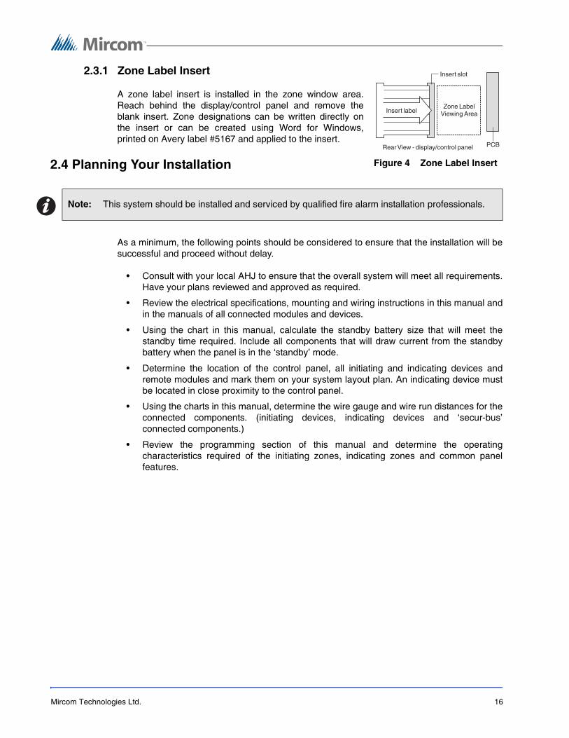
2.3.1 Zone Label Insert
A zone label insert is installed in the zone window area.Reach behind the display/control panel and remove theblank insert. Zone designations can be written directly onthe insert or can be created using Word for Windows,printed on Avery label #5167 and applied to the insert.
2.4 Planning Your Installation
As a minimum, the following points should be considered to ensure that the installation will besuccessful and proceed without delay.
• Consult with your local AHJ to ensure that the overall system will meet all requirements.Have your plans reviewed and approved as required.
• Review the electrical specifications, mounting and wiring instructions in this manual andin the manuals of all connected modules and devices.
• Using the chart in this manual, calculate the standby battery size that will meet thestandby time required. Include all components that will draw current from the standbybattery when the panel is in the ‘standby’ mode.
• Determine the location of the control panel, all initiating and indicating devices andremote modules and mark them on your system layout plan. An indicating device mustbe located in close proximity to the control panel.
• Using the charts in this manual, determine the wire gauge and wire run distances for theconnected components. (initiating devices, indicating devices and ‘secur-bus’connected components.)
• Review the programming section of this manual and determine the operatingcharacteristics required of the initiating zones, indicating zones and common panelfeatures.
Note: This system should be installed and serviced by qualified fire alarm installation professionals.
Figure 4 Zone Label Insert

Mircom Technologies Ltd. 17
2.5 Electrical Specifications
Table 1 Electrical Specifications
Circuit / Model(s) Rating
Primary AC 120 volts, 60 Hz. 1.5 Amps maximum/
240 volts, 50 Hz. 1.0 Amps maximum
AUX+ 500 mA maximum Restoral of Aux Power shorts requires removal of all Aux Power loading
SCOM 500 mA maximum (current sink)
COM 500 mA maximum (current sink)
Relays (common alarm & trouble) Form ‘C’ contact, 2 Amp, 30 VDC resistive, power limited source
NAC Outputs 24 volts, full-wave rectified DC, 1.5 Amps max
Power limited
3.0 Amps total for both NAC circuits
EOLR 4.7K ohm, ½ W, 5%
Initiating Zone Inputs 24 VDC, 60 mA max.(in alarm)
Supervisory current: 6.0 mA – max
Loop resistance: 100 ohms max.
EOLR: 4.7 K ohm, ½ W, 5%
Battery Charging Current 270mA maximum
Low Battery Trouble Low Battery Trouble: 22.0 VDC
Low Battery Trouble Restore: 23.0 VDC
Critical Shutdown: 19±0.5 VDC

Mircom Technologies Ltd. 18
2.6 Module Current Ratings
Table 2 Module Current Ratings
2.7 Standby Battery calculation chart
1. All components that draw current from the panel while it is in the ‘standby’ mode (AC OFF) must be considered for the standby battery calculation. All components that draw current while in the ‘Alarm’ mode must be considered for the alarm battery calculation.
2. The control panel will always draw the currents as shown in the chart.
3. Typically the alarm current is calculated assuming only one initiating zone is in alarm. If it is required that more than one zone be considered, add 60 mA per zone in the Alarm column. Consult the smoke detector manufacture’s installation sheet to determine the standby current of these devices. Write that number in the ‘current per device’ column then multiply that number by the number of devices on the zone. Repeat for each zone.
4. Consult the Notification Appliance installation sheet to determine the current draw for each device connected to the NAC. For each NAC, calculate the total current in alarm and put that number (mA) in the ‘Alarm’ column.
5. For each added module in the system, multiply the number of modules times the module ‘standby’ and ‘alarm’ currents and write those totals in the ‘standby’ and ‘alarm’ columns.
6. Add up all the current drawn from the AUX+ output in the standby and alarm mode and put those totals in the ‘standby’ and ‘alarm’ columns.
7. Add up all the currents in the ‘standby’ column and the ‘Alarm’ column.
8. Convert the ‘standby’ and ‘alarm’ currents from mA to Amps. (divide mA by 1000)
Module Standby Current(mA) DC
Alarm Current (mA)DC
Max. Alarm Current(mA) DC
FA-265 Control panel 130 475* 715
RTI-265 Remote trouble indicator 15 15 15
RAM-265 R.T.I. and remote 5 zone annunciator
15 20* 40
UDACT-286 DACT 45 60 60
RM-263 Relay module** 0 24 24
Notes: *Current noted assumes ONE initiating zone is in alarm. The “Max. Alarm Current” assumes all zones are in alarm.
**Values shown are for all relays set for activation on ‘Alarm’. Each relay set for activation on ‘trouble’ is normally energized and on ‘AC fail’ will draw 0 mA.
Note: Each NAC can supply 1.5 Amps max.
Mircom Technologies Ltd. 19
9. Write in the ‘standby’ time required. (24 or 60 Hr.)
10. Multiply the ‘standby’ Amps times the ‘standby’ time to get the ‘standby’ Amp-Hr. required.
11. Write in the ‘alarm’ time required in hours. (5 min. =.08 Hr.; 30 min. =0.5 Hr.)
12. Multiply the ‘alarm’ Amps times the ‘alarm’ time to get the ‘alarm’ Amp-Hr required.
13. Add the ‘standby’ Amp-Hr. to the ‘alarm’ Amp-Hr. for the total Amp-Hr. required.
14. Multiply the total Amp-Hr. times 1.20 for the minimum Amp-Hr. battery required to support the system for the selected ‘standby time and the selected ‘alarm’ time.

Mircom Technologies Ltd. 20
2.7.1 Calculation for Standby Battery Requirement
Step Device Currentperdevice(mA)
Numberofdevice
TotalStandbyCurrent(mA)
Total AlarmCurrent(mA)
1 FA-265 Standby: 130 x 1 = 130
Alarm: 415 x 1 = 415
2 Zone 1 Standby: x =
Alarm: 69 x 1 = 69
Zone 2 Standby: x =
Alarm: 69 x 1 =
Zone 3 Standby: x =
Alarm: 69 x 1 =
Zone 4 Standby: x =
Alarm: 69 x 1 =
Zone 5 Standby: x =
Alarm: 69 x 1 =
3 NAC 1 Alarm: x =
NAC 2 Alarm: x =
4 RTI-265 Standby: 15 x
Alarm: 15 x
RAM-265 Standby: 15 x
Alarm: 25 x
UDACT-286 Standby: 45 x
Alarm: 60 x
RM-263 Standby: 0 x =
Alarm: 24 x
5 AUX+ Standby: x =
Alarm: x =
6 Total ‘standby’ and ‘alarm’ current: mA mA
7 Divide ‘standby’ mA and ‘alarm’ mA by 1000: Amp Amp

Mircom Technologies Ltd. 21
Table 3 Battery Calculation Chart
Select a battery with an Amp-Hr. rating that is equal to or larger than the calculated minimumAmp-Hr. battery required.
8 Select ‘standby’ time required (24 or 60 Hr.): Hr.
9 Standby Amp-Hr. - multiply 8 × 7 = (Amps × Hr.): Amp-Hr.
10 Select ‘alarm’ time required (0.08 or 0.5): Hr.
11 Alarm Amp-Hr. - multiply 7 × 10 = (Amps × Hr.): Amp-Hr.
12 Total Amp-Hr = standby Amp-Hr (9) + alarm Amp-Hr. (11): Amp-Hr.
13 Multiply the total Amp-Hr. by the safety margin: 1.20
14 Total battery Amp-Hr required to support the system: Amp-Hr.
Note: The maximum battery allowed is 26 Ah. Install batteries outside the panel box. Total “Standby”current is not to exceed 0.5 Amperes.
Step Device Currentperdevice(mA)
Numberofdevice
TotalStandbyCurrent(mA)
Total AlarmCurrent(mA)

Mircom Technologies Ltd. 22
3 Installing the FA-265 FirePanel
3.1 Environmental Specifications
Consider the following conditions when selecting a mounting location for the FA-265 panel:
• Operating temperature: 32°F to 122°F / 0°C to 50°C
• Humidity: 95% RH non-condensing
• Close to a source of unswitched AC power

Mircom Technologies Ltd. 23
3.2 Panel Assembly and Modules Locations
The panel comes completely assembled from the factory. Remove the lower dead front foraccess to the battery compartment. Remove display control panel for access to ACconnections.
Figure 5 Panel Assembly and Modules Locations
240V 50Hz120V 60Hz
GNDN
Primary AC

Mircom Technologies Ltd. 24
3.3 Mounting the FA-265
Figure 6 Mounting Dimensions
Figure 7 Knockout Locations
Dimensions in inches

Mircom Technologies Ltd. 25
4 Wiring the FA-2654.1 Wiring Specifications
Figure 8 FA-265 Terminals Descriptions
TerminalLabel
Description
NAC 1
(+, –)
Notification Appliance Circuit # 1
24 VDC, Full-Wave Rectified voltage, 1.5 Amps max.
Programmable as Steady or Temporal output on alarm.
Supervised for opens, shorts and ground fault.
Power limited.
NAC 2
(+, –)
Notification Appliance Circuit # 2
24 VDC, Full-Wave Rectified voltage, 1.5 Amps max.
Programmable as Steady or Temporal output on alarm.
Supervised for opens, shorts and ground fault.
Power limited
AUX+ Auxiliary power output
24 VDC, filtered and regulated, 500 mA max., 400 mV P-P ripple, power limited. Aux power shorts must be restored by removing all Aux Power loading.
COM Auxiliary common power return, unswitched
24 VDC, 500 mA max.
SCOM Auxiliary common power return, switched
(open circuit on system reset or on 4-wire smoke detector reset)
24 VDC, 500 mA max. (Please refer to Appendix A for compatible 4-wire smoke detectors.)
DAT Data line for remote module communications
CLK Clock line for remote module communications
TRB NO Common Trouble relay, Normally Open contact
TRB C Common Trouble relay, Common contact
Mircom Technologies Ltd. 26
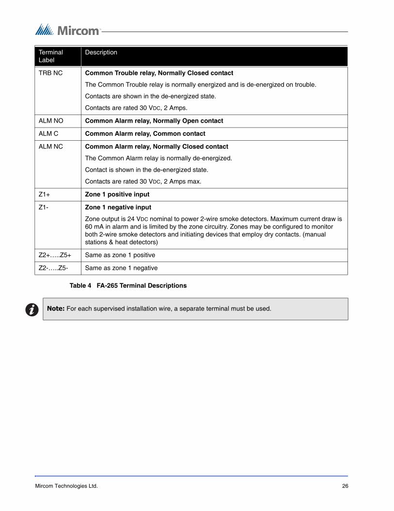
Table 4 FA-265 Terminal Descriptions
TRB NC Common Trouble relay, Normally Closed contact
The Common Trouble relay is normally energized and is de-energized on trouble.
Contacts are shown in the de-energized state.
Contacts are rated 30 VDC, 2 Amps.
ALM NO Common Alarm relay, Normally Open contact
ALM C Common Alarm relay, Common contact
ALM NC Common Alarm relay, Normally Closed contact
The Common Alarm relay is normally de-energized.
Contact is shown in the de-energized state.
Contacts are rated 30 VDC, 2 Amps max.
Z1+ Zone 1 positive input
Z1- Zone 1 negative input
Zone output is 24 VDC nominal to power 2-wire smoke detectors. Maximum current draw is 60 mA in alarm and is limited by the zone circuitry. Zones may be configured to monitor both 2-wire smoke detectors and initiating devices that employ dry contacts. (manual stations & heat detectors)
Z2+…..Z5+ Same as zone 1 positive
Z2-…..Z5- Same as zone 1 negative
Note: For each supervised installation wire, a separate terminal must be used.
TerminalLabel
Description

Mircom Technologies Ltd. 27
4.1.1 2-Wire and 4-Wire Devices Typical Wiring
Figure 9 Connecting 2-Wire Alarm Initiating Devices
• Maximum 30 smoke detectors per zone (100 μA each standby).
• Manual station, heat detector.
• Maximum total loop wire resistance = 100 ohms.
• Program zone as:Type 1 - Smoke and contact devices instant alarm (default)Type 2 - Smoke auto-verify and contact as instant.
Figure 10 Connecting 4-Wire Smoke Detectors
• Program as zone type 01, instant alarm.
• Maximum total loop wire resistance is 100 ohms.
Note: * See Chapter 10 FCC Compliance Statement on page 64 in this manual for a list of compatible2-wire smoke detectors.

Mircom Technologies Ltd. 28
4.1.2 Zone Wiring Chart
Table 5 Zone Wiring Chart
4.2 Connecting NAC Devices (Class ‘A’ and Class ‘B’)
Figure 11 Connecting NAC Devices (Class ‘B’)
Figure 12 Connecting NAC Devices (Class ‘A’)
Wire
(Gauge)
Distance
(feet)
Distance
(meters)
18 7,690 2,345 Maximum loop resistance is 100 ohms. Maximum current in alarm is 60 mA.16 12,195 3,717
14 19,230 5,861
Mircom Technologies Ltd. 29
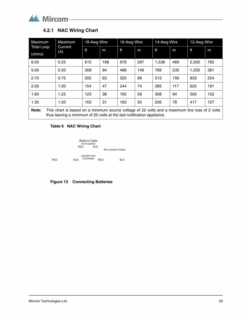
4.2.1 NAC Wiring Chart
Table 6 NAC Wiring Chart
Figure 13 Connecting Batteries
MaximumTotal Loop
(ohms)
MaximumCurrent(A)
18-Awg Wire 16-Awg Wire 14-Awg Wire 12-Awg Wire
ft m ft m ft m ft m
8.00 0.25 615 188 978 297 1,538 469 2,500 762
5.00 0.50 308 94 488 149 769 235 1,250 381
2.70 0.75 205 63 325 99 513 156 833 254
2.00 1.00 154 47 244 74 385 117 625 191
1.60 1.25 123 38 195 59 308 94 500 152
1.30 1.50 103 31 163 50 256 78 417 127
Note: This chart is based on a minimum source voltage of 22 volts and a maximum line loss of 2 voltsthus leaving a minimum of 20 volts at the last notification appliance.

Mircom Technologies Ltd. 30
Figure 14 Connecting AC Power
Figure 15 Connecting the Alarm and Trouble Relays
Figure 16 Connecting Optional Devices
See installation sheets for the remote devices for detailed wiring and address setup.
• Maximum of 4 RTI-265 per panel.
• Maximum of 4 RAM-265 per panel.
240V 50Hz 120V 60Hz
GND N
Primary AC
Note: The wire gauges must be no less then the size required by the Canadian Electrical Code C22.1, Part 1, Section 32.
Mircom Technologies Ltd. 31
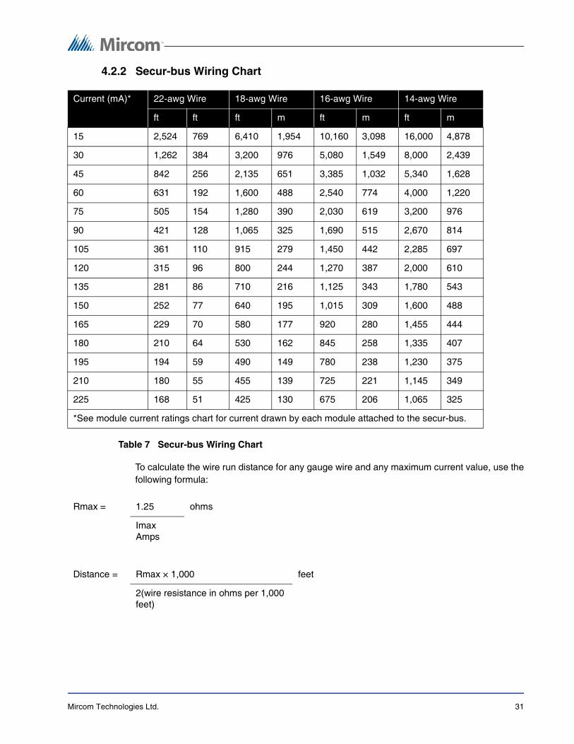
4.2.2 Secur-bus Wiring Chart
Table 7 Secur-bus Wiring Chart
To calculate the wire run distance for any gauge wire and any maximum current value, use thefollowing formula:
Current (mA)* 22-awg Wire 18-awg Wire 16-awg Wire 14-awg Wire
ft ft ft m ft m ft m
15 2,524 769 6,410 1,954 10,160 3,098 16,000 4,878
30 1,262 384 3,200 976 5,080 1,549 8,000 2,439
45 842 256 2,135 651 3,385 1,032 5,340 1,628
60 631 192 1,600 488 2,540 774 4,000 1,220
75 505 154 1,280 390 2,030 619 3,200 976
90 421 128 1,065 325 1,690 515 2,670 814
105 361 110 915 279 1,450 442 2,285 697
120 315 96 800 244 1,270 387 2,000 610
135 281 86 710 216 1,125 343 1,780 543
150 252 77 640 195 1,015 309 1,600 488
165 229 70 580 177 920 280 1,455 444
180 210 64 530 162 845 258 1,335 407
195 194 59 490 149 780 238 1,230 375
210 180 55 455 139 725 221 1,145 349
225 168 51 425 130 675 206 1,065 325
*See module current ratings chart for current drawn by each module attached to the secur-bus.
Rmax = 1.25 ohms
Imax Amps
Distance = Rmax × 1,000 feet
2(wire resistance in ohms per 1,000 feet)

Mircom Technologies Ltd. 32
Secur-bus Capacitance
Maximum wire capacitance for proper operation of the Secur-bus is 90 nF (nanofarad). Typicalwire capacitance for 22 awg quad cable is 20 nF per 1,000 feet. Thus, for 22 awg quad cable,the maximum wire run distance is ((90/20)× 1,000) = 4,500 feet. Other types of wire havedifferent capacitance values. Consult the wire manufacturer’s data sheets for typicalcapacitance values.
The following devices may be connected to the Secur-bus. All devices are supervised. See thesection 6.3.7 Entering the Reset Programming Mode on page 48 for information on addingand deleting devices on the Secur-bus.
Table 8 Secur-bus Devices
Note: Shielded wire has a much higher capacitance value and distances are severely reduced.
Devices Description
RTI-265 External to control panel. Up to 4 of each device may be connected.
RAM-265
UDACT-286 Mounted inside control panel. See diagram in Figure 5 Panel Assembly and Modules Locations on page 23.
Notes: Do not run the Secur-bus adjacent to sources of high transient noise such as AC wiring, telephone cable bundles or computer wiring.
If the Secure-bus must go through a high transient area, use shielded cable.
If shielded cable is used, the distances in the chart above are cut in half.

Mircom Technologies Ltd. 33
5 Panel Operation5.1 Operating Sequences
This section describes how the panel functions under various conditions. The choices youmake in panel programming will also affect how the panel operates. Please see Chapter 6 FA-265 System Programming on page 39 for information on how to program the panel, anddescriptions of each of the programming options.
5.2 General Zone Fire Alarms
Zone alarms have priority over all other annunciation. When an alarm occurs, the followinghappens:
• The corresponding zone alarm LED begins flashing, the common alarm LED turns onsteady, and the alarm relay turns on.
• If a trouble was present on that zone then the zone trouble LED turns off. If the troublebuzzer is audible then it also turns off.
• The NACs sound in a steady or temporal pattern, depending on the option selected (see6.3.2 NAC Sounding Rate Programming on page 44).
• If enabled, the silence inhibit timer begins counting down (see 6.3.4 Signal SilenceInhibit Timer and Walk Test Programming on page 46). If the silence inhibit timer isenabled, the panel cannot be silenced for 60 seconds following the first fire alarm.Subsequent fire alarms do not restart or extend this timer. While the signal silence inhibittimer is counting down, if the Silence Alarm button is pressed the panel will sound a 1second ‘error tone’ on the common trouble buzzer.
• The NACs remain on until silenced with the Silence Alarm button, or if the automaticalarm silence is enabled, until the thirty minute bell timer runs out (see 6.3.3 NACAutomatic Signal Silence and NAC2 Strobe Mode Programming on page 45). If theautomatic silence timer is enabled, the panel will automatically silence the NACs 30minutes after the last fire alarm. Each zone alarm will restart the timer, giving a full 30minutes after the last alarm before the NACs are silenced.
• Once the NACs are silenced the signals silenced LED turns on and any flashing zonealarm LEDs turn on steady. The common trouble LED and trouble relay also turn onand, if the NACs have been silenced automatically, the buzzer will sound at a rate of ½second ON/OFF.
• Any additional zone alarms that occur while the panel is in alarm will reset the autoalarm silence timer and turn on the NACs, but the panel will not restart the 60 secondsilence inhibit timer.
• The zone alarm LEDs, common alarm LED and alarm relay will remain on steady until asystem reset is performed.
Note: A manual signal silence will not initiate the trouble buzzer. Only the common trouble LED andsignals silenced LED are turned on.

Mircom Technologies Ltd. 34
5.3 Waterflow Alarms
If the Waterflow Silence option is turned off (see 6.3.5 Waterflow Alarms Programming onpage 47), when a waterflow zone (type 03) initiates an alarm the NACs cannot be silenceduntil all waterflow zones are returned to normal. If all waterflow zones return to normal after the30 minute automatic signal silence timer has expired, then the panel will silence the NACs.
If the Waterflow Silence option is turned on, then an alarm on a waterflow zone is treated likeany other fire alarm.
5.4 Supervisory Zone Alarms
When an alarm occurs on a supervisory zone (type 04), the corresponding zone supervisoryLED begins flashing. The common supervisory LED and supervisory relay (supervisory relayis optional) turn on steady, and the buzzer turns on steady. If there was a trouble on that zone,the zone trouble LED turns off. The buzzer remains on until the trouble silence button ispressed. Once the buzzer is silenced any flashing zone supervisory LEDs turn on steady. Thezone supervisory LEDs, common supervisory LED and supervisory relay remain on steadyuntil a system reset is performed.
5.4.1 Subsequent Fire Supervisory
After silencing a fire supervisory, a subsequent fire supervisory from another zone will resoundthe trouble/supervisory buzzer and the new zone supervisory LED flashes until the SilenceTrouble button is pressed.
5.4.2 Supervisory / Trouble Priority
If a supervisory zone has a trouble and it goes into alarm, the zone trouble LED isextinguished until that zone is restored and the panel has been reset. The common troubleLED will remain on steady until all supervisory alarms have been restored and the panel reset.All other ‘common’ trouble indicators will operate normally.
5.4.3 Supervisory / Fire Alarm Priority
The supervisory zone LED, the common supervisory LED and the buzzer (in the steadysupervisory mode) function normally whether there is a fire alarm present or not.
5.5 Trouble Operation
When a trouble occurs, if there is a corresponding trouble LED it turns on steady. The commontrouble LED and the trouble relay also turn on. If no alarm is present on the system, the buzzerwill sound at a rate of ½ second ON/OFF. The buzzer and trouble LEDs will remain on until thetrouble is restored. If the Silence Trouble button is pressed, the buzzer turns off. Subsequenttroubles will resound the trouble buzzer.
Note: If there is no trouble present in the system then pressing the Silence Trouble button will result ina 1 second error tone.

Mircom Technologies Ltd. 35
5.5.1 System Troubles
For a list of system faults that will initiate a trouble see the following table.
Table 9 System Faults and Troubles
System faults CommonTroubleLED
Buzzer TroubleRelay
Other Indicators
Alarm zone open circuit – loss of EOLR
turns on sounds ½ second on/off
deactivates Zone trouble LED turns on steady
NAC open circuit or short circuit turns on sounds ½ second on/off
deactivates NAC1 or NAC2 trouble LED turns on
Battery low voltage or disconnected
turns on sounds ½ second on/off
deactivates Battery LED turns on
Signals silenced - automatically turns on sounds ½ second on/off
deactivates Signals Silenced LED turns on
Ground on extended conductor turns on sounds ½ second on/off
deactivates Ground LED turns on
AC fails completely, or is low for more than 10 seconds (brownout)
turns on sounds ½ second on/off
deactivates AC LED turns off
Installer Programming Mode Active
flashes sounds ½ second on/off
deactivates AC LED turns off
Loss of Remote Trouble Unit turns on sounds ½ second on/off
deactivates
Loss of Remote Alarm/Trouble Unit
turns on sounds ½ second on/off
deactivates
TLM on one or both telephone lines (Dialer)
turns on sounds ½ second on/off
deactivates
Failure to communicate (Dialer) turns on sounds ½ second on/off
deactivates
Unsuccessful system reset turns on sounds ½ second on/off
deactivates
Loss of Dialer module turns on sounds ½ second on/off
deactivates

Mircom Technologies Ltd. 36
5.6 System Reset Operation
To reset the system, press the ‘Reset System’ button. The panel will remove all power from thezones and the switched auxiliary relay for 10 seconds. During this 10 second period, thebuzzer will beep twice every 2 seconds.
The panel can only be reset if all waterflow zones are restored (only applies if the SilenceWaterflow option is turned off - see 6.3.5 Waterflow Alarms Programming on page 47).
If the panel is not in a condition to be reset, when the ‘Reset System’ button is pressed thepanel will sound a 1 second error tone on the buzzer.
After the 10 second reset period, the panel will turn off the zone LED for any zones that havebeen restored. If one or more zones is still in alarm after the reset period, the panel willactivate the NACs as programmed. If there are no alarms but one or more Supervisory zonesis still ‘off-normal’ after the reset period, the panel will sound the trouble buzzer in theSupervisory mode. If there are no alarms or supervisory conditions but a trouble is present inthe panel after the reset period, the panel will sound the trouble buzzer. After the reset period,LEDs for any alarms, supervisory off-normal or trouble conditions will be on.
5.7 Lamp Test
The lamp test will check all of the panel and annunciator LEDs. To do a lamp test, press andhold the Lamp Test button. All the LEDs will flash.
A lamp test will only work if the NACs are not active and the supervisory buzzer is not active. Ifa lamp test is unsuccessful the buzzer will sound a 1 second error tone. If any trouble or zonehas a state change during lamp test, the lamp test will be cancelled and the panel will return tonormal operation.

Mircom Technologies Ltd. 37
5.8 Walk Test (Installer function only)
To do a walk test, all zone alarms, troubles and relays must be in their normal state. You canprogram the walk test to be either audible or silent (see 6.3.4 Signal Silence Inhibit Timer andWalk Test Programming on page 46).
1. To walk test the panel press the Walk Test button. The common trouble LED flashes and the buzzer sounds one short beep. The panel will be in walk test mode for one hour, or until you press the Walk Test button again.
2. As you test each part of the system, the panel will give the following indications:
Zone LEDs operate normally except that alarms do not latch - the alarm LEDs will turn offwhen the zone is restored and the auto-reset has been successful.
Alarm and trouble relays are NOT activated. If used, any remote connection is not activated.
3. To return the system to normal operation, press the Walk Test button. If you do not press the Walk Test button, the system will return to normal operation after one hour. If any zones are in alarm at the end of the walk test, the zones will indicate silenced signals.
Type of activation LEDs NACs* Trouble Buzzer
Fire Alarm or Fire Supervisory Zone alarm/Supv LED turns on 1 squawk
Fire Alarm or Fire Supervisory Restoral
Zone alarm/Supv LED turns off 1 squawk
Zone or System Trouble Zone or system trouble LED turns on 2 squawks Sounds
Zone or System Trouble Restoral Zone or system trouble LED turns off 2 squawks Stops sounding
Ground Fault Ground trouble LED turns on 3 squawks Sounds
Ground Fault Restoral Ground trouble LED turns off 3 squawks Stops sounding
Note: *Only if Walk Test Audible option is turned on.
Note: The Lamp Test button does not work while the panel is in Walk Test mode.Walk Test function notavailable without AC power.

Mircom Technologies Ltd. 38
5.9 NAC operation
See also 6.3.2 NAC Sounding Rate Programming on page 44, and 6.3.4 Signal Silence InhibitTimer and Walk Test Programming on page 46 for more information.
5.9.1 Class ‘B’ operation selections:• Steady (default) – On alarm the NAC will turn on steady. It will turn off on either a
manual or automatic signal silence.
• Temporal 3 – On alarm the NAC will turn on with the temporal 3 pattern and turn off oneither a manual or automatic signal silence.
• NAC2 Strobe – On alarm NAC2 will turn on steady. It will not turn off on a manual orautomatic signal silence. NAC2 set in this mode will only turn off on system reset if allzone fire alarms are restored. Only NAC2 can be set in this mode.
5.9.2 Class ‘A’ operation selections
If the panel NACs are set for class ‘A’ operation then there is only one NAC. In thisconfiguration the NAC output can only be set for steady or temporal using the NAC1programming options For class ‘A’, the NAC2 Strobe option is not available.
5.10 Relay Function
5.10.1 Alarm Relay
The panel activates the alarm relay upon any (non-supervisory) zone alarm. The paneldeactivates the alarm relay upon a successful system reset.
5.10.2 Trouble Relay
The panel deactivates the trouble relay upon any system trouble. The panel activates thetrouble relay upon the restoral of all system troubles.
5.10.3 Supervisory Relay (available with the RM-263 Relay Expander only)
The panel activates the supervisory relay upon any supervisory zone alarm. The paneldeactivates the supervisory relay upon a successful system reset.

Mircom Technologies Ltd. 39
6 FA-265 SystemProgramming
Programming the FA-265 System is done using the Silence Trouble, Alarm Silence controlsand the indicator LEDs. Programmed operating mode data is stored in non-volatile memorythat retains the information if the power to the panel is removed.
The following are the FA-265 System Programmable Functions
• Zone Programming
• NAC Sounding Rate
• NAC Auto-Silence and NAC2 Strobe Mode
• 60 Second Signal Silence Inhibit and Audible Walk Test
• Waterflow Programming
• Reference AC Line Frequency (50 or 60 Hz)
There are two additional operational modes that can be performed, the Reset ProgrammingMode and Viewing the Event Buffer. For more information on
The Reset Programming Mode can perform the following.
• Adding and Removing a Module
• Defaulting the System
During Installer Programming Mode, each Programmable Function is displayed on the panelusing the LED Indicators.

Mircom Technologies Ltd. 40
6.1 Entering Installer Programming Mode
All zone alarms must be reset prior to entering the Installer Programming Mode. While thepanel is in Installer Programming Mode, the annunciators will show a trouble condition.
How to enter Installer Programming Mode
1. Remove the lower front cover and locate the ‘Walk Test Switch’ behind the control panel PCB, as shown in Figure 17 Locating the Walk Test Switch.
2. Press and hold the Walk Test Switch for two seconds. The common trouble buzzer and common trouble LED turn on and pulse ½ second on/off.
3. Press any button. The trouble buzzer is silent, and the zone 1 alarm LED turns on steady. The common trouble LED continues to flash.
4. The panel is now ready to program.
Figure 17 Locating the Walk Test Switch
Mircom Technologies Ltd. 41
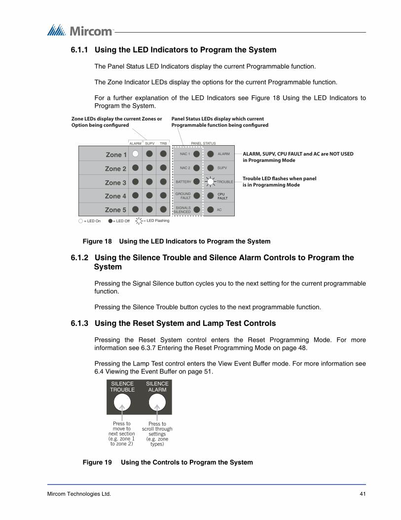
6.1.1 Using the LED Indicators to Program the System
The Panel Status LED Indicators display the current Programmable function.
The Zone Indicator LEDs display the options for the current Programmable function.
For a further explanation of the LED Indicators see Figure 18 Using the LED Indicators toProgram the System.
Figure 18 Using the LED Indicators to Program the System
6.1.2 Using the Silence Trouble and Silence Alarm Controls to Program the System
Pressing the Signal Silence button cycles you to the next setting for the current programmablefunction.
Pressing the Silence Trouble button cycles to the next programmable function.
6.1.3 Using the Reset System and Lamp Test Controls
Pressing the Reset System control enters the Reset Programming Mode. For moreinformation see 6.3.7 Entering the Reset Programming Mode on page 48.
Pressing the Lamp Test control enters the View Event Buffer mode. For more information see6.4 Viewing the Event Buffer on page 51.
Figure 19 Using the Controls to Program the System
CPUFAULT
Zone LEDs display the current Zones or
Option being configured
Panel Status LEDs display which current
Programmable function being configured
ALARM, SUPV, CPU FAULT and AC are NOT USED
in Programming Mode
Trouble LED flashes when panel
is in Programming Mode

Mircom Technologies Ltd. 42
6.2 Programming and Exiting the System
How to Program the System
1. Enter Installer Programming Mode. For details on how to do so see 6.1 Entering Installer Programming Mode on page 40.
2. Press the Signal Silence button to select the correct option for the Programmable Function.
3. Press the Silence Trouble button to cycle to the next function.
4. Repeat steps 2-3 until all Programmable Functions are completed. You are now ready to exit the Installer Programming Mode.
How to Exit the System
1. To exit Installer Programming Mode press the Silence Trouble button.
2. Upon exiting the Installer Programming Mode, the panel performs a system reset for 10 seconds, during which the buzzer sounds double beeps. When the beeping stops the panel returns to normal operating mode and all programming choices are stored in memory.
6.3 Programming Function Descriptions
6.3.1 Zone Programming
Zone Programming is the first Programmable function. Each of the 5 zones can be configuredas one of the following:
• Instant Alarm
• Waterflow Zone
• Supervisory Zone
• Not Used
Use all 5 Zone Alarm, Supervisory and Trouble LED’s to program this function.
Press the Silence Alarm control to cycle through the programmable settings for each zone.
Press the Silence Trouble control to cycle through the Zones. To proceed to the nextprogramming function cycle through all 5 zones.
The Trouble LED flashes when the panel is in any Programming Mode.
No other Panel Status LED’s will be lit.
Notes: To exit the Installer Programming Mode at any other point in the panel programming, press and hold the Walk Test switch for two seconds.
If 5 minutes elapse without any button presses, the panel will automatically exit the Installer Programming Mode. During the final 60 seconds before the exit, the panel will sound a warning tone on the buzzer. Press any button to cancel the auto-exit and resume programming.

Mircom Technologies Ltd. 43
Table 10 LED Indicators for Zone Programming
Panel Status LED Alarm, Supervisory andTrouble LED’s
Programmable Setting Description
Instant Alarm
Instant alarm for 2-wire smoke detectors, 4-wire smoke detector and contact devices.
Acivating a 2-wire smoke detector, 4 –wire smoke detector or contact device instantly causes the panel to enter alarm.
Any zone entering alarm causes any in progress auto-verify sequence on another zone to be cancelled and both zones will indicate an alarm condition.
Waterflow Zone
This zone type is intended for waterflow alarm initiating contact devices only. Do not mix other alarm initiating devices on this zone.
For Waterflow delay, use actuating devices with a built-in delay of 30 seconds or more. The overall maximum waterflow alarm initiation delay allowed is 90 seconds. (NFPA A-5-6.2 – 1996 edition)
Activating the contact on a Waterflow alarm initiating device instantly causes the control panel to enter alarm.
Supervisory Zone
Initiating a contact on a Supervisory device causes the control panel to immediately indicate the Supervisory “off-normal” condition
The zone supervisory LED flashes yellow, the common ‘supervisory’ LED illuminates steady and the common trouble buzzer sounds steady. Pressing the ‘trouble silence’ switch will silence the buzzer, the zone supervisory LED ceases flashing and turns on steady.
Fire supervisory zones are latching and can only be restored after restoring the initiating device and resetting the system.
Not Used
The zone is not used. The zone is not supervised, alarms and troubles are ignored. The end-of-line resistor is not required.
CPUFAULT

Mircom Technologies Ltd. 44
6.3.2 NAC Sounding Rate Programming
NAC1 and NAC2 can be configured to sound at either steady or temporal rate. The defaultrate is steady.
Use the Zone 1 and Zone 2 Alarm, Supervisory and Trouble LED’s to program this function.
Press the Silence Alarm control to cycle through the programmable settings for each function.
Press the Silence Trouble control to cycle through the Zones. To proceed to the nextprogramming function cycle through the 2 zones.
The Trouble LED flashes when the panel is in programming mode.
The NAC1 Panel Status LED will illuminate steady.
Table 11 LED Indicators for NAC Sounding Rate Programming
Panel Status LED Alarm, Supervisory andTrouble LED’s
Programmable Setting Description
Steady (default)
The NAC will sound continuously.
Temporal
The NAC will sound the Temporal/ANSI Fire Pattern: 0.5 seconds ON, 0.5 seconds OFF, 0.5 seconds ON, 0.5 seconds OFF, 0.5 seconds ON, 1.5 seconds OFF, repeat.
CPUFAULT

Mircom Technologies Ltd. 45
6.3.3 NAC Automatic Signal Silence and NAC2 Strobe Mode Programming
Use the Zone 1 Alarm, Supervisory and Trouble LED’s to enable or disable the AutomaticSignal Silence function.
Use the Zone 2 Alarm, Supervisory and Trouble LED’s to enable NAC2 Strobe Mode function.
Press the Silence Alarm control to cycle through the programmable settings for each function.
Press the Silence Trouble control to cycle through the Zones. To proceed to the nextprogramming function cycle through the 2 zones.
The Trouble LED flashes when the panel is in programming mode.
The NAC2 Panel Status LED will illuminate steady.
Table 12 LED Indicators for NAC Auto SIlence and NAC2 Strobe Mode Programming
Panel Status LED Alarm, Supervisory andTrouble LED’s
Programmable Setting Description
Automatic Signal Silence disabled
The panel will not silence the NACs automatically.
Automatic Signal Silence enabled
Silences all alarms and restores the panel to normal 30 minutes after the last alarm. Subsequent alarms after silencing causes the NAC’s to resound and restarts the 30 minute Automatic Signal Silence timer.
NAC2 Strobe Mode disabled
An automatic signal silence (see above) or pressing the SIlence Alarm button restores NAC2 to normal.
NAC2 Strobe Mode enabled
NAC2 is not silenced by the Silence Alarm button or by the Automatic Signal Silence function. NAC2 can only be turned off when all zone fire alarms are restored and the system is reset. Only NAC2 can be set to this mode.
CPUFAULT
Zone 1
Auto-Silence
DISABLED
Zone 1
Signal Silence
Inhibit Timer
ENABLED
Zone 2
NAC2 Strobe
Mode
DISABLED
Zone 2
NAC2 Strobe
Mode
ENABLED

Mircom Technologies Ltd. 46
6.3.4 Signal Silence Inhibit Timer and Walk Test Programming
Use the Zone 1 Alarm, Supervisory and Trouble LED’s to enable or disable the Signal SilenceInhibit timer function.
Use the Zone 2 Alarm, Supervisory and Trouble LED’s to enable or silence the Audible WalkTest function.
Press the Silence Alarm control to cycle through the programmable settings for each function.
Press the Silence Trouble control to cycle through the Zones. To proceed to the nextprogramming function cycle through the 2 zones.
The Trouble LED flashes when the panel is in programming mode.
The Battery Panel Status LED will illuminate steady.
Table 13 LED Indicators for Signal Silence Inhibit Timer and Audible Walk TestProgramming
Panel Status LED Alarm, Supervisory andTrouble LED’s
Programmable Setting Description
Signal Silence Inhibit Timer Disabled (default)
Pressing the Silence Alarm button turns off the NACs at any time.
Setting NAC2 as a strobe disables removes the ability to silence NAC2 by pressing the Silence Alarm Button.
See 6.3.3 NAC Automatic Signal Silence and NAC2 Strobe Mode Programming on page 45.
Signal Silence Inhibit Timer Enabled
The panel begins a 60 second countdown when the first alarm activates. During this 60 seconds, users will not be able to turn off the NACs by pressing the Silence Alarm button. The timer starts on the first alarm only and does not restart on subsequent alarms.
Audible Walk Test - Audible
Setting the One Man Walk Test to audible, causes the following:
The bells pulse ONCE on a fire or Supervisory alarm/restoral
The bells pulse TWICE on a zone or system trouble/restoral, excluding a ground fault.
The bells pulse THREE times on any ground fault.
Audible Walk Test - Silent
The bells will not sound during the walk test.
CPUFAULT
Zone 1
Signal Silence
Inhibit Timer
DISABLED
Zone 1
Signal Silence
Inhibit Timer
ENABLED
Zone 2
Audible
Walk Test
AUDIBLE
Zone 2
Audible
Walk Test
SILENT

Mircom Technologies Ltd. 47
6.3.5 Waterflow Alarms Programming
Use the Zone 1 Alarm, Supervisory and Trouble LED’s to enable or disable the WaterflowDelay Timer function.
Use the Zone 2 Alarm, Supervisory and Trouble LED’s to enable or silence the SilenceWaterflow Alarms function.
Press the Silence Alarm control to cycle through the programmable settings for each function.
Press the Silence Trouble control to cycle through the Zones. To proceed to the nextprogramming function cycle through the 2 zones.
The Trouble LED flashes when the panel is in programming mode.
The Ground Fault Status LED will illuminate steady.
Table 14 LED Indicators for Waterflow Alarms Programming
Panel Status LED Alarm, Supervisory andTrouble LED’s
Programmable Setting Description
Waterflow Delay Timer Disabled (default)
Alarms on Waterflow zones causes an immediate alarm in the panel.
Waterflow Delay Timer Enabled
The panel starts a 60 second timer when the first Waterflow zone enters alarm. The panel will not restart the timer on subsequent Waterflow zone alarms. When the timer expires, if any waterflow zone is still in alarm, the panel will immediately go into alarm. If any other type of fire zone enters alarm during the waterflow delay countdown, the panel immediately enters alarm.
Silence Waterflow Alarms Enabled (default)
Waterflow zones can be silenced without being physically restored.
Silence Waterflow Alarms Disabled
Waterflow zones cannot be silenced until they are physically restored. This applies to both automatic signal silence, and the Silence Alarm button. If there is a trouble on a Waterflow zone following the alarm and alarm restore, the zone can be silenced.
CPUFAULT
Zone 1
Waterflow
Delay Timer
DISABLED
Zone 1
Waterflow
Delay Timer
ENABLED
Zone 2
Silence
Waterflow
Alarm
ENABLED
Zone 2
Silence
Waterflow
Alarm
DISABLED

Mircom Technologies Ltd. 48
6.3.6 Reference AC Line Frequency (50 or 60 Hz)
Use the Zone 2 Alarm, Supervisory and Trouble LED’s to select the Reference AC LineFrequency.
Press the Silence Alarm control to cycle through the programmable settings,
Press the Silence Trouble control to cycle through the Zones. To proceed to the nextprogramming function cycle through the 2 zones.
The Trouble LED flashes when the panel is in programming mode.
The Ground Fault Status LED will illuminate steady.
Table 15 LED Indicators for Reference AC Line Frequency (50 or 60 Hz)
6.3.7 Entering the Reset Programming Mode
The Reset Programming mode allows for the following
• Removing a Module
• Adding a Module
• Default the System
Enter the Reset Programming Mode as described in the following steps
How to enter the Reset Programming Mode
1. Enter the Installer Programming Mode as described in 6.1 Entering Installer Programming Mode on page 40.
2. To enter the Reset Programming mode, press and hold the System Reset button for 2 seconds. The Zone1 Alarm LD and Trouble LED will be ON and all the System Trouble LEDs will flash Once in the Installer Programming Mode, the Reset Programming Mode can be accessed at any time.
Panel Status LED Alarm, Supervisory andTrouble LED’s
Programmable Setting Description
50 Hz
60 Hz (default)
CPUFAULT
Zone 2
50 Hz
Zone 2
60 Hz

Mircom Technologies Ltd. 49
6.3.8 Removing a Module from the System
How to Remove a Modules from the System
1. Physically remove the module from the system and enter the reset section programming as described above.
2. Enter the Reset Programming Mode as described above.
3. Press the ‘Silence Alarm’ button until the Z1 SUPV LED is ON.
4. Press the ‘Silence Trouble’ button to exit the Reset Programming Mode.The common trouble buzzer and common trouble LED turn on and pulse ½ second on/off.
5. Press any button to re-enter the Installer Programming Mode. The trouble buzzer is silent and the zone 1 alarm LED turns on steady. The common trouble LED continues to flash. You can now cycle through the Installer Programming Mode.
6. To exit immediately, press and hold the Walk Test button for 2 seconds.
7. Upon exit the system will reset the ‘supervision’ field for all the modules currently connected to the ‘secur-bus.
Table 16 Removing an Module from the System
6.3.9 Adding a Module to the System
Physically connecting the module to the system will allow the module to auto-enroll within oneminute. No additional programming is required.
Panel Status LED Alarm, Supervisory andTrouble LED’s
Programmable Setting Description
Removing a Module from the System
CPUFAULT
Zone 2
Removing
a Module

Mircom Technologies Ltd. 50
6.3.10 Defaulting the System
How to Default the System
1. Enter the Reset Programming Mode as described above.
2. Press the ‘Silence Trouble’ button to go to Zone 2
3. Press the ‘Silence Alarm’ button once to illuminate the Zone 2 Supervisory LED.
4. Press the ‘Silence Trouble’ button to exit the Reset Programming Mode. The common trouble buzzer and common trouble LED turn on and pulse ½ second on/off.
5. Press any button to re-enter the Installer Programming Mode. The trouble buzzer is silent and the zone 1 alarm LED turns on steady. The common trouble LED continues to flash. You can now cycle through the Installer Programming Mode.
6. To exit immediately, press and hold the Walk Test button for 2 seconds.
7. Upon exit, the system will reset all of the panel programmable parameters to their factory default state. Please note that the ‘supervision’ field will be reset as well.
Table 17 LED Indicators for Defaulting the System
Panel Status LED Alarm, Supervisory andTrouble LED’s
Programmable Setting Description
Defaulting the System
CPUFAULT
Zone 2
Defaulting
the System

Mircom Technologies Ltd. 51
6.4 Viewing the Event Buffer
The Event Buffer stores up to 20 events. For a complete description of the Events see Table18 Event Buffer Table on page 52
How to View the Event Buffer
1. Enter the Installer Programming Mode by pressing and holding the Walk Test switch for 2 seconds.
2. Press any switch. To silence the trouble buzzer and enter the Installer Programming mode.
3. Press and hold the Lamp Test switch for 2 seconds.
4. The Common Supervisory LED flashes to indicate the View Buffer mode.
5. Events are shown from the most recent to the oldest.
6. See the event table below which indicates the LED patterns used to indicate various events.
7. To advance to the next event press the Silence Trouble switch.
8. Once all 20 events have been viewed, the next Silence Trouble keypress will exit the view buffer mode and return to the Installer Programming Mode programming. To exit the Installer Programming Mode, press and hold for 2 seconds the Walk Test switch.
9. Pressing the Silence Signal switch at any time will cause the system to exit the View Buffer mode. The buzzer will sound. Press any button to go to the Installer Programming Mode.
Figure 20 LED Indicators for Viewing the Event Buffer
Panel Status and Alarm, Supervisory and Trouble LEDs
CPUFAULT

Mircom Technologies Ltd. 52
Table 18 Event Buffer Table
Display Event
Steady Common Alarm LED Null Event
Flashing Zone X Alarm LED Verified Zone X Alarm
Steady Zone X Alarm LED Verified Zone X Alarm Restore
Flashing Zone X Alarm LED and Flashing Zone X Supervisory LED
Unverified Zone X Alarm
Flashing Zone X Supervisory LED Zone X Supervisory
Steady Zone X Supervisory LED Zone X Supervisory Restore
Flashing Zone X Trouble LED Zone X Trouble
Steady Zone X Trouble LED Zone X Trouble Restore
Flashing Common Trouble LED Expansion Module Fault
Steady Common Trouble LED Expansion Module Fault Restore
Flashing NAC1 Trouble LED NAC 1 Trouble
Steady NAC1 Trouble LED NAC 1 Trouble Restore
Flashing NAC2 Trouble LED NAC 2 Trouble
Steady NAC2 Trouble LED NAC 2 Trouble Restore
Flashing Battery Trouble LED Battery Trouble
Steady Battery Trouble LED Battery Trouble Restore
Flashing Ground Fault LED Ground Fault Trouble
Steady Ground Fault LED Ground Fault Restore
Flashing Signal Silenced Trouble LED Manual Signal Silence
Steady Signal Silenced Trouble LED (Successful) Reset
Flashing AC On LED AC Failure
Steady AC On LED AC Fail Restore
Steady AC On LED and Steady BAT TRB LED
Cold Start
Flashing AC On LED and Flashing BAT TRB LED
Warm Start
Flashing (ALL) Zone Trouble LED’s Walk Test Start / Installer Mode Entry
Steady (ALL) Zone Trouble LED’s Walk Test End / Installer Mode Exit

Mircom Technologies Ltd. 53
7 Startup of the FA-2657.1 Prior to power up
• Verify that all field wiring is free of shorts, opens and grounds and that end-of-linedevices are connected and are the proper value.
• Verify that all modules and internal cables are properly seated in their location.
• Verify that all metal components are bonded to the incoming ground. Should measurezero ohms between any metal part and the incoming ground wire.
• Verify that the polarity between the panel and connected devices is correct.
7.2 Power up sequence
• Connect AC power first before Battery.
• The panel goes into the Reset mode immediately. This lasts for 10 seconds and thetrouble buzzer will beep during the reset period.
• After the reset period ends, the buzzer goes silent, the green AC indicator should be ONand all other LEDs should be OFF.
• If any LED other than the AC LED is ON then there is a fault in the system. Troubleshootand repair the fault before proceeding.
• If the battery is not fully charged, the battery fault LED will come on after about 2minutes. Verify that the battery is connected properly and if it is, it may take up to 24hours to recharge the batteries. Once the battery is charged, the battery fault LED willgo OFF.
7.3 Default Operation
• On first power up, all programmable features will be in the default mode.
• Do a ‘Lamp Test’ to verify that all the indicators function.
• It is suggested that an initial verification of operation be done before the panel isprogrammed. Verify that each zone will go into alarm and that each NAC operates theNotification Appliances and that the zone alarm indicator(s) function. Each zone isdefaulted as an instant ‘fire alarm’ and each NAC is defaulted for ‘steady’ output onalarm. An Alarm, Silence, Reset cycle will also verify that the push-button functionproperly.
• Verify that each zone indicates a trouble on a zone open and that a ground fault on theextended conductors is properly indicated.

Mircom Technologies Ltd. 54
7.4 Programming the Panel
• Program the panel for the operational features desired. (section 6)
• Record your configuration choices for future reference. (section 8)
• Verify panel operations and feature selections by initiating alarms and troubles asdescribed above.
7.5 Final Verification
• Verify system operation and fault detection as required by the local Authority HavingJurisdiction.
• Enable the ‘one-man’ walk test feature to test all the field devices and wiring.

Mircom Technologies Ltd. 55
8 Programming Worksheets8.1 Entering the Installer Programming Mode
Please see Chapter 6 FA-265 System Programming on page 39 for complete instructions.
To enter the Installer Programming Mode:
1. Press and hold the Walk Test button for two seconds (located behind the display PCB).
2. Press any button to turn off the trouble buzzer.
3. Press Silence Alarm to scroll through the settings for each programming section (e.g. to change the zone type, or to turn an option on or off).
4. Press Silence Trouble to move to the next programming section (e.g. to move from zone 1 to zone 2).
5. The panel will indicate the current programming section using the Common Trouble LEDs, as shown below:
Please see 6.3 Programming Function Descriptions on page 42 for detailed descriptions ofeach programming section.
Note: All zone alarms must be reset prior to entering the Installer Programming Mode. While the panelis in the Installer Programming Mode, the annunciators will show a trouble condition.

Mircom Technologies Ltd. 56
8.2 Zone Programming
Program each of the zones as one of the following types. (See 6.3.1 Zone Programming onpage 42.) Record your programming choices in the table below.
8.3 NAC Temporal/Steady Programming (Section 1)
Please see 6.3.2 NAC Sounding Rate Programming on page 44.
* = Factory default
ZONEALARMLED On
ZoneNo.
Type
(00 - 05)
Label
1 1
2 2
3 3
4 4
5 5
ZONEALARMLED On
Programming Section Settings
1 NAC1 Temporal / Steady Temporal *Steady
2 NAC2 Temporal / Steady Temporal *Steady

Mircom Technologies Ltd. 57
8.4 NAC Auto-silence, Strobe Programming (Section 2)
Please see 6.3.3 NAC Automatic Signal Silence and NAC2 Strobe Mode Programming onpage 45.
* = Factory default
8.5 Silence Inhibit and Walk Test Programming (Section 3)
Please see 6.3.4 Signal Silence Inhibit Timer and Walk Test Programming on page 46.
* = Factory default
8.6 Waterflow Programming (Section 4)
Please see 6.3.5 Waterflow Alarms Programming on page 47.
* = Factory default
ZONEALARMLED On
Programming Section Settings
1 NAC Auto-silence Enabled *Disabled
2 NAC2 Strobe or Bell Strobe *Bell
ZONEALARMLED On
Programming Section Settings
1 Signal Silence Inhibit Timer Enabled *Disabled
2 One Man Walk Test *Audible Silent
ZONEALARMLED On
Programming Section Settings
1 Waterflow Delay Timer Enabled *Disabled
2 Silencing of Waterflow Alarms *Enabled Disabled

Mircom Technologies Ltd. 58
8.7 50/60Hz Option (Section 5)
* = Factory default
ZONEALARM LEDOn
Programming Section Settings
2 AC power 50Hz or 60Hz *60Hz 50Hz

Mircom Technologies Ltd. 59
9 Appendix: ULI CompatibleSmoke Detectors
PanelCID
Max. #Detectors
Manufacturer Model Model
CID
Base BaseCID
Description
01 25 System Sensor 1400/1400A
A N/A N/A Ionization type smoke, 2-wire 12/24VDC
01 25 System Sensor 1451 A B401
B401B
N/A Plug-in – Ionization type smoke detector
01 25 System Sensor 2400 A N/A N/A Photoelectric, 2-wire, 12/24VDC
01 25 System Sensor 2400TH A N/A N/A Photoelectric with Thermal, 2-wire, 12/24VDC
01 25 System Sensor 2400AT A N/A N/A Photoelectric with Thermal and Horn, 2-wire, 24VDC
01 25 System Sensor 2400AIT A N/A N/A Photoelectric with isolated Thermal and Horn, 2-wire, 24VDC
01 25 System Sensor 2451 A B401
B401B
DH400
N/A Plug-in – Photoelectric type smoke detector
01 25 System Sensor 2451TH A B401
B401B
N/A Plug-in – Photoelectric type smoke detector with Thermal
01 25 System Sensor 1100 A N/A N/A Ionization, 2-wire, 12/24VDC, terminal strip
01 25 System Sensor 2100 A N/A N/A Photoelectric, 2-wire, 12/24VDC, terminal strip
01 25 System Sensor 2100T A N/A N/A Photoelectric, 2-wire, 12/24VDC, thermistor, terminal strip
01 25 System Sensor 2112/24T A N/A N/A Photoelectric, 12/24VDC, terminal strip

Mircom Technologies Ltd. 60
Table 19 ULI Compatible Smoke Detectors
01 25 System Sensor 4451HT
4451HTA
A B401
B401B
DH400
N/A Plug-in – High Temp Heat 88°C (190°F)
01 25 System Sensor 5451 A B401
B401B
DH400
N/A Plug-in – Fixed Temp/Rate of Rise Detector
01 25 System Sensor 1151
1151A
A B401
B401B
DH400
N/A Plug-in – Low Profile Ion
01 25 System Sensor 2151
2151A
A B401
B401B
DH400
N/A Plug-in – Low Profile Photo
01 25 System Sensor 2100S A N/A N/A 2-wire direct wire Photoelectric
01 25 System Sensor 2100TS A N/A N/A 2-wire direct wire Photoelectric Thermal
01 30 System Sensor 2100AT A N/A N/A 2-wire direct wire Photoelectric Audible Thermal
01 30 System Sensor 2100TR A N/A N/A 2-wire direct wire Photoelectric Thermal Auxiliary Relay
PanelCID
Max. #Detectors
Manufacturer Model Model
CID
Base BaseCID
Description

Mircom Technologies Ltd. 61
9.1 ULI Compatible Smoke Detector Bases
Table 20 ULI Compatible Smoke Detector Bases
9.2 ULI Compatible 4-Wire Smoke Detectors
Table 21 ULI Compatible 4-Wire Smoke Detectors
Max. #Detectors
Manufacturer Model BaseCID
Description
25 System Sensor B401 N/A 2-wire standard base, 4”, 12/24VDC
25 System Sensor B401B N/A 2-wire standard base, 6”, 12/24VDC
25 System Sensor B406B N/A 2-wire base, 24VDC, form contact
25 System Sensor B401BH N/A 24VDC sounder base for use with B401
25 System Sensor B110LP N/A 2-wire, flangeless, 12/24VDC
25 System Sensor B116LP N/A 2-wire base, 24VDC, form contact
25 System Sensor DH400 N/A Duct Detector Mount
25 System Sensor RMK400 N/A Recessed mount kit for Series 400
Manufacturer Models
System Sensor
1124B 2124B 2124TB 2124S 2124TS 2124R
2124TR 2124AT 2124ATR 2124AITR 1424 2424
2424TH 2424AT 1151* 2151* - -
2424AIT 6424 1451** 2451** 22451TH** -
*Detector with B112LP Base **Detector with B402B Base
Detection Systems
DS284 DS284TH DS284THS DS284THR DS284THSR DS284THCS
DS284THC DS284THE DS284ES DS284IS - -
Gentex 8240 8240T 8240P 8243P 8240PH 8243PH
8240PT 8243PT - - - -
Hochiki SIJ-24 SLR-24 SLR-24H SLR-835B - -
DSC MN240 MN240T MN240R MN240RT MN240S MN240ST
MN240SR MN240SRT - - - -
ESL 741U 741UT - - - -

Mircom Technologies Ltd. 62
9.3 ULI Compatible Horns/Strobes
Table 22 ULI Compatible System Sensor Horns/Strobes
Table 23 ULI Compatible Gentex Horns/Strobes
System Sensor Type Cd Voltage (FWR)
P2415(W)(A) H/S 15 20-30
P241575(W)(A) H/S 15/75 20-30
P2475(W)(A) H/S 75 20-30
P24110(W)(A) H/S 110 20-30
S2415(W)(A) S 15 20-30
S241575(W)(A) S 15/75 20-30
S2475(W)(A) S 75 20-30
S24110(W)(A) S 110 20-30
H24(W)(A) H - 20-30
MDL(W)(A) Synch Module 20-30
No suffix = Red, suffix W = White, suffix A = Canadian version
Gentex Type Cd Voltage (FWR)
GEH24 H - 20-31
GES24-15 S 15 20-31
GES24-15/75 S 15/75 20-31
GES24-30 S 30 20-31
GES24-60 S 60 20-31
GES24-75 S 75 20-31
GES24-110 S 110 20-31
GEC24-15 H/S 15 20-31
GEC24-15/75 H/S 15/75 20-31
GEC24-30 H/S 30 20-31
GEC24-60 H/S 60 20-31
GEC24-75 H/S 75 20-31
GEC24-110 H/S 110 20-31
Available in Red and White.
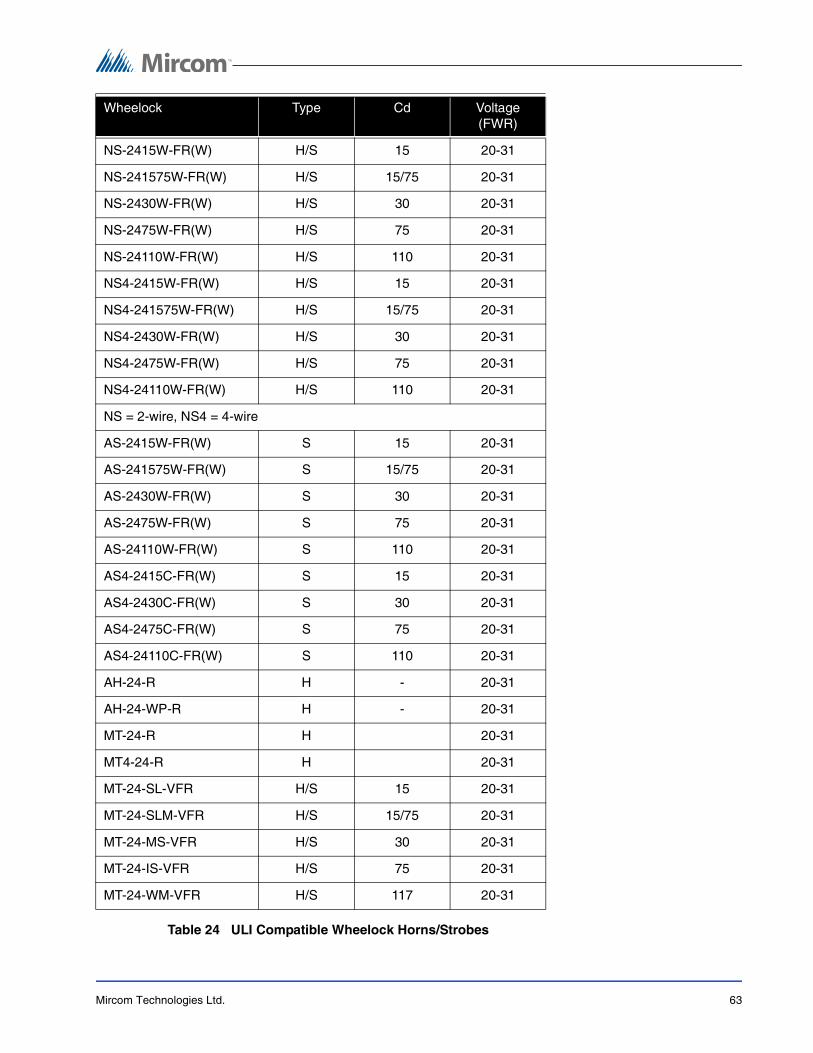
Mircom Technologies Ltd. 63
Table 24 ULI Compatible Wheelock Horns/Strobes
Wheelock Type Cd Voltage (FWR)
NS-2415W-FR(W) H/S 15 20-31
NS-241575W-FR(W) H/S 15/75 20-31
NS-2430W-FR(W) H/S 30 20-31
NS-2475W-FR(W) H/S 75 20-31
NS-24110W-FR(W) H/S 110 20-31
NS4-2415W-FR(W) H/S 15 20-31
NS4-241575W-FR(W) H/S 15/75 20-31
NS4-2430W-FR(W) H/S 30 20-31
NS4-2475W-FR(W) H/S 75 20-31
NS4-24110W-FR(W) H/S 110 20-31
NS = 2-wire, NS4 = 4-wire
AS-2415W-FR(W) S 15 20-31
AS-241575W-FR(W) S 15/75 20-31
AS-2430W-FR(W) S 30 20-31
AS-2475W-FR(W) S 75 20-31
AS-24110W-FR(W) S 110 20-31
AS4-2415C-FR(W) S 15 20-31
AS4-2430C-FR(W) S 30 20-31
AS4-2475C-FR(W) S 75 20-31
AS4-24110C-FR(W) S 110 20-31
AH-24-R H - 20-31
AH-24-WP-R H - 20-31
MT-24-R H 20-31
MT4-24-R H 20-31
MT-24-SL-VFR H/S 15 20-31
MT-24-SLM-VFR H/S 15/75 20-31
MT-24-MS-VFR H/S 30 20-31
MT-24-IS-VFR H/S 75 20-31
MT-24-WM-VFR H/S 117 20-31

Mircom Technologies Ltd. 64
10 FCC ComplianceStatement
CAUTION: Changes or modifications not expressly approved by the manufacturer could voidyour authority to use this equipment.
This equipment has been tested and found to comply with the limits for a Class B digitaldevice, pursuant to Part 15 of the FCC Rules. These limits are designed to provide reasonableprotection against harmful interference in a residential installation. This equipment generates,uses and can radiate radio frequency energy and, if not installed and used in accordance withthe instructions, may cause harmful interference to radio communications. However, there isno guarantee that interference will not occur in a particular installation. If this equipment doescause harmful interference to radio or television reception, which can be determined byturning the equipment off and on, the user is encouraged to try to correct the interference byone or more of the following measures:
• Re-orient the receiving antenna.
• Increase the separation between the equipment and receiver.
• Connect the equipment into an outlet on a circuit different from that to which the receiveris connected.
• Consult the dealer or an experienced radio/television technician for help.
The user may find the following booklet prepared by the FCC useful: “How to Identify andResolve Radio/Television Interference Problems”. This booklet is available from the U.S.Government Printing Office, Washington D.C. 20402, Stock # 004-000-00345-4.

Mircom Technologies Ltd. 65
11 Warranty & WarningInformation
11.1 Warning Please Read Carefully
Note to End User
This equipment is subject to terms and conditions of sale as follows:
11.1.1 Note to Installers
This warning contains vital information. As the only individual in contact with system users, it isyour responsibility to bring each item in this warning to the attention of the users of this system.Failure to properly inform system end-users of the circumstances in which the system mightfail may result in over-reliance upon the system. As a result, it is imperative that you properlyinform each customer for whom you install the system of the possible forms of failure.
11.1.2 System Failures
This system has been carefully designed to be as effective as possible. There arecircumstances, such as fire or other types of emergencies where it may not provide protection.Alarm systems of any type may be compromised deliberately or may fail to operate asexpected for a variety of reasons. Some reasons for system failure include:
Inadequate Installation
A Fire Alarm system must be installed in accordance with all the applicable codes andstandards in order to provide adequate protection. An inspection and approval of the initialinstallation, or, after any changes to the system, must be conducted by the Local AuthorityHaving Jurisdiction. Such inspections ensure installation has been carried out properly.
Power Failure
Control units, smoke detectors and many other connected devices require an adequate powersupply for proper operation. If the system or any device connected to the system operates frombatteries, it is possible for the batteries to fail. Even if the batteries have not failed, they mustbe fully charged, in good condition and installed correctly. If a device operates only by ACpower, any interruption, however brief, will render that device inoperative while it does not havepower. Power interruptions of any length are often accompanied by voltage fluctuations whichmay damage electronic equipment such as a fire alarm system. After a power interruption hasoccurred, immediately conduct a complete system test to ensure that the system operates asintended.
Failure of Replaceable Batteries
Systems with wireless transmitters have been designed to provide several years of battery lifeunder normal conditions. The expected battery life is a function of the device environment,usage and type. Ambient conditions such as high humidity, high or low temperatures, or largetemperature fluctuations may reduce the expected battery life. While each transmitting devicehas a low battery monitor which identifies when the batteries need to be replaced, this monitor

Mircom Technologies Ltd. 66
may fail to operate as expected. Regular testing and maintenance will keep the system in goodoperating condition.
Compromise of Radio Frequency (Wireless) Devices
Signals may not reach the receiver under all circumstances which could include metal objectsplaced on or near the radio path or deliberate jamming or other inadvertent radio signalinterference.
System Users
A user may not be able to operate a panic or emergency switch possibly due to permanent ortemporary physical disability, inability to reach the device in time, or unfamiliarity with thecorrect operation. It is important that all system users be trained in the correct operation of thealarm system and that they know how to respond when the system indicates an alarm.
Automatic Alarm Initiating Devices
Smoke detectors, heat detectors and other alarm initiating devices that are a part of thissystem may not properly detect a fire condition or signal the control panel to alert occupants ofa fire condition for a number of reasons, such as: the smoke detectors or heat detector mayhave been improperly installed or positioned; smoke or heat may not be able to reach thealarm initiating device, such as when the fire is in a chimney, walls or roofs, or on the other sideof closed doors; and, smoke and heat detectors may not detect smoke or heat from fires onanother level of the residence or building.
Software
Most Mircom products contain software. With respect to those products, Mircom does notwarranty that the operation of the software will be uninterrupted or error-free or that thesoftware will meet any other standard of performance, or that the functions or performance ofthe software will meet the user’s requirements. Mircom shall not be liable for any delays,breakdowns, interruptions, loss, destruction, alteration or other problems in the use of aproduct arising our of, or caused by, the software.
Every fire is different in the amount and rate at which smoke and heat are generated. Smokedetectors cannot sense all types of fires equally well. Smoke detectors may not provide timelywarning of fires caused by carelessness or safety hazards such as smoking in bed, violentexplosions, escaping gas, improper storage of flammable materials, overloaded electricalcircuits, children playing with matches or arson.
Even if the smoke detector or heat detector operates as intended, there may be circumstanceswhen there is insufficient warning to allow all occupants to escape in time to avoid injury ordeath.
Alarm Notification Appliances
Alarm Notification Appliances such as sirens, bells, horns, or strobes may not warn people orwaken someone sleeping if there is an intervening wall or door. If notification appliances arelocated on a different level of the residence or premise, then it is less likely that the occupantswill be alerted or awakened. Audible notification appliances may be interfered with by othernoise sources such as stereos, radios, televisions, air conditioners or other appliances, orpassing traffic. Audible notification appliances, however loud, may not be heard by a hearing-impaired person.

Mircom Technologies Ltd. 67
Telephone Lines
If telephone lines are used to transmit alarms, they may be out of service or busy for certainperiods of time. Also the telephone lines may be compromised by such things as criminaltampering, local construction, storms or earthquakes.
Insufficient Time
There may be circumstances when the system will operate as intended, yet the occupants willnot be protected from the emergency due to their inability to respond to the warnings in atimely manner. If the system is monitored, the response may not occur in time enough toprotect the occupants or their belongings.
Component Failure
Although every effort has been made to make this system as reliable as possible, the systemmay fail to function as intended due to the failure of a component.
Inadequate Testing
Most problems that would prevent an alarm system from operating as intended can bediscovered by regular testing and maintenance. The complete system should be tested asrequired by national standards and the Local Authority Having Jurisdiction and immediatelyafter a fire, storm, earthquake, accident, or any kind of construction activity inside or outsidethe premises. The testing should include all sensing devices, keypads, consoles, alarmindicating devices and any other operational devices that are part of the system.
Security and Insurance
Regardless of its capabilities, an alarm system is not a substitute for property or life insurance.An alarm system also is not a substitute for property owners, renters, or other occupants to actprudently to prevent or minimize the harmful effects of an emergency situation.
IMPORTANT NOTE
End-users of the system must take care to ensure that the system, batteries, telephone lines,etc. are tested and examined on a regular basis to ensure the minimization of system failure.
11.2 Limited Warranty
Mircom Technologies Ltd. warrants the original purchaser that for a period of three years fromthe date of shipment, the product shall be free of defects in materials and workmanship undernormal use. During the warranty period, Mircom Technologies Ltd. shall, at its option, repair orreplace any defective product upon return of the product to its factory, at no charge for laborand materials. Any replacement and/or repaired parts are warranted for the remainder of theoriginal warranty or ninety (90) days, whichever is longer. The original owner must promptlynotify Mircom Technologies Ltd. in writing that there is defect in material or workmanship, suchwritten notice to be received in all events prior to expiration of the warranty period.
11.2.1 International Warranty
The warranty for international customers is the same as for any customer within Canada andthe United States, with the exception that Mircom Technologies Ltd. shall not be responsible forany customs fees, taxes, or VAT that may be due.

Mircom Technologies Ltd. 68
11.2.2 Conditions to Void Warranty
This warranty applies only to defects in parts and workmanship relating to normal use. It doesnot cover:
• damage incurred in shipping or handling
• damage caused by disaster such as fire, flood, wind, earthquake or lightning
• damage due to causes beyond the control of Mircom Technologies Ltd. such asexcessive voltage, mechanical shock or water damage
• damage caused by unauthorized attachment, alterations, modifications or foreignobjects
• damage caused by peripherals (unless such peripherals were supplied by MircomTechnologies Ltd.)
• defects caused by failure to provide a suitable installation environment for the products
• damage caused by use of the products for purposes other than those for which it wasdesigned
• damage from improper maintenance
• damage arising out of any other abuse, mishandling or improper application of theproducts.
11.3 Warranty Procedure
To obtain service under this warranty, please return the item(s) in question to the point ofpurchase. All authorized distributors and dealers have a warranty program. Anyone returninggoods to Mircom Technologies Ltd. must first obtain an authorization number. MircomTechnologies Ltd. will not accept any shipment whatsoever for which prior authorization hasnot been obtained. NOTE: Unless specific pre-authorization in writing is obtained from Summitmanagement, no credits will be issued for custom fabricated products or parts or for completefire alarm system. Summit will at its sole option, repair or replace parts under warranty.Advance replacements for such items must be purchased.Mircom Technologies Ltd.
11.4 Disclaimer of Warranties
This warranty contains the entire warranty and shall be in lieu of any and all other warranties,whether expressed or implied (including all implied warranties of merchantability or fitness for aparticular purpose) And of all other obligations or liabilities on the part of Mircom TechnologiesLtd. neither assumes nor authorizes any other person purporting to act on its behalf to modifyor to change this warranty, nor to assume for it any other warranty or liability concerning thisproduct. This disclaimer of warranties and limited warranty are governed by the laws of theprovince of Ontario, Canada.
Note: ’s liability for failure to repair the product under this warranty after a reasonable number ofattempts will be limited to a replacement of the product, as the exclusive remedy for breach ofwarranty.

Mircom Technologies Ltd. 69
11.5 Out of Warranty Repairs
Mircom Technologies Ltd. will at its option repair or replace out-of-warranty products which arereturned to its factory according to the following conditions. Anyone returning goods to MircomTechnologies Ltd. must first obtain an authorization number. Mircom Technologies Ltd. will notaccept any shipment whatsoever for which prior authorization has not been obtained.
Products which Mircom Technologies Ltd. determines to be repairable will be repaired andreturned. A set fee which Mircom Technologies Ltd. has predetermined and which may berevised from time to time, will be charged for each unit repaired.
Products which Mircom Technologies Ltd. determines not to be repairable will be replaced bythe nearest equivalent product available at that time. The current market price of thereplacement product will be charged for each replacement unit.
The FA-265 fire alarm control panel is designed to meet the requirements of NFPA 72, 2002edition, UL 864 Rev 9, Control Units for Fire Protective Systems, and in Canada, CAN/ULC-S527-99, Standard for Control Units for Fire Alarm Systems.
Information provided with this unit is intended as a guide. Installation of this equipment,optional system components, alarm initiating devices and notification appliances must followthe manufacturer’s guidelines as contained in their respective installation documents, allapplicable codes and the instructions of the Local Authority Having Jurisdiction.
The foregoing information is accurate as of the date of publishing and is subject to change orrevision without prior notice at the sole discretion of the Company.
WARNING: Mircom Technologies Ltd. recommends that the entire system be completely tested on a regular basis. However, despite frequent testing, and due to, but not limited to, criminal tampering or electrical disruption, it is possible for this product to fail to perform as expected.
NOTE: Under no circumstances shall Mircom Technologies Ltd. be liable for any special, incidental, or consequential damages based upon breach of warranty, breach of contract, negligence, strict liability, or any other legal theory. Such damages include, but are not limited to, loss of profits, loss of the product or any associated equipment, cost of capital, cost of substitute or replacement equipment, facilities or services, down time, purchaser’s time, the claims of third parties, including customers, and injury to property.
MIRCOM MAKES NO WARRANTY OF MERCHANTABILITY OR FITNESS FOR A PARTICULAR PURPOSE WITH RESPECT TO ITS GOODS DELIVERED, NOR IS THERE ANY OTHER WARRANTY,

Mircom Technologies Ltd. 70


Canada 25 Interchange Way Vaughan, ON L4K 5W3 Tel: 905-660-4655 Fax: 905-660-4113
© Mircom 2010Printed in Canada Subject to change without prior notice
www.mircom.com
U.S.A. 4575 Witmer Industrial EstatesNiagara Falls, NY 14305Tel: 1-888-660-4655 Fax: 1-888-660-4113