Embed Size (px)
Citation preview

UL and the UL logo are trademarks of UL LLC © 2015
Fire and Gas Characterization
Studies for Lithium-ion
Cells and Batteries
Daniel Juarez Robles, Ph. D., Judy Jeevarajan, Ph.D.
Electrochemical Safety
Underwriters Laboratories Inc.
November 17, 2020
2020 NASA Aerospace Battery Workshop

Motivation
2
Thermal Runaway
Thermal runaway is defined as the incident when an electrochemical cell increases its temperature
through self-heating in an uncontrollable fashion.
• Thermal runaway propagates when the cell’s generation of heat is at a higher rate than the
heat it can dissipate.
• The intent of this project is to severely abuse a single cell such that it is most likely to enter
thermal runaway with the presumption that a single cell may enter thermal runaway during
transport.
• Under certain severe failure conditions, lithium-based rechargeable cells can emit gases
which may be harmful to humans and/or may form a combustible mixture in sufficient
concentrations. Examples may include, but are not limited to, carbon monoxide (CO),
carbon dioxide (CO2), hydrogen (H2), organic solvent vapors and hydrogen fluoride (HF).
Research Topic
3
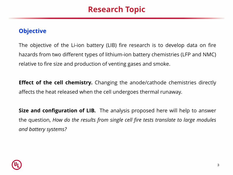
Objective
The objective of the Li-ion battery (LIB) fire research is to develop data on fire
hazards from two different types of lithium-ion battery chemistries (LFP and NMC)
relative to fire size and production of venting gases and smoke.
Effect of the cell chemistry. Changing the anode/cathode chemistries directly
affects the heat released when the cell undergoes thermal runaway.
Size and configuration of LIB. The analysis proposed here will help to answer
the question, How do the results from single cell fire tests translate to large modules
and battery systems?

Test Samples
4
Single Cell Module Battery
25 Ah, Single Cell
E = [2.7, 4.2] V
5.5 Ah, Single Cell
E = [2.0, 3.6] V
75 Ah, 3P Configuration
E = [2.7, 4.2] V
82.5 Ah, 15P Configuration
E = [2.0, 3.6] V
75 Ah, 3P4S Configuration
E = [10.8, 16.8] V
82.5 Ah, 15P4S Configuration
E = [8.0, 14.4] V

Test Setup
5
• Cathode Chemistry :
NMC (Prismatic), LFP (Cylindrical)
• Battery Scale :
Single Cell, Module, Battery
• State of Charge: 100% SOC
• Heater Specs: 120 V, 10 W/in2
NMC: 4” × 6”, LFP: 2” × 2”
• Heating Profile:
UL 9540A, “Test Method for Evaluating Thermal Runaway Fire Propagation”
HR = 10 °C/min to a hold temperature of 200 °C
• Temperature Measurements: K-Thermocouple (30 AWG)
• Gas Analysis:
Organic compounds. Fourier Transform Infrared Spectrometry (FTIR).
Gas composition. Gas Chromatography – Mass Spectrometry.

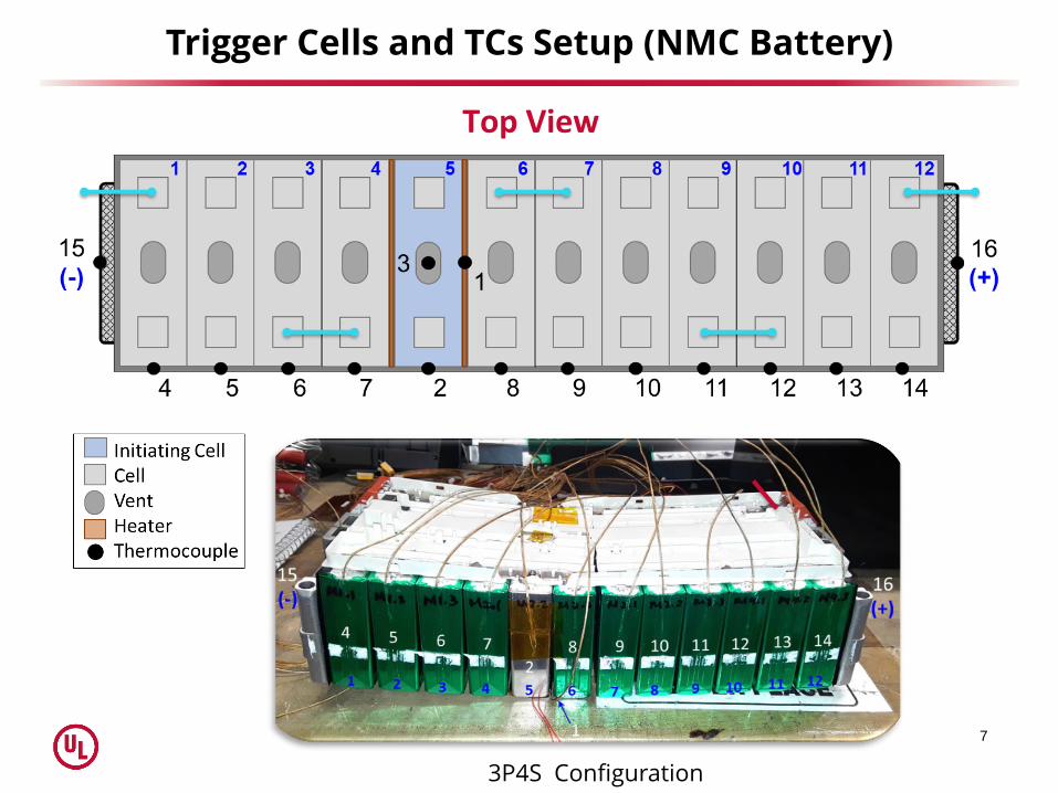
Trigger Cells and TC Configuration
6
NMC
LFPFlexible film heaters
7
Trigger Cells and TCs Setup (NMC Battery)
Top View
3P4S Configuration

Trigger Cell and TCs Setup (LFP Battery)
8
Front Back
15P4S Configuration
The module labels are only a reference to its position inside the battery.
RESULTS
Temperature Response

LFP – Temperature Response
Single Cell Module SmokeSmoke
LFP single cell and
module had one case
where smoke and fire
was observed.

11
LFP Battery – Test
16.8 V; 82.5 Ah (1.26 kWh)
• The outer plastic case was softened on all faces and breached in several locationswhere gas venting was observed.
• Some solidified piles of particulate, resembling plastic, were observed aroundareas where steady venting occurred.
Battery after the test

LFP Battery – Temperature Response
6 trigger cells2 trigger cells

NMC – Temperature Response
Single Cell ModuleOnly Smoke Smoke and Fire

14
NMC Battery – Test
Trigger Cell
Activated vent holes
Cell metal casingmelting
Cell rupture
14.8 V; 75 Ah (1.1 kWh)
Flame jetted from the cell ventsas well as ruptures on the sidesof the cell casing.
Thermal runaway occurred in all the cells.

NMC Battery – Temperature Response
1 trigger cell

Sample Size Effect
NMC 𝑻𝑻𝑹 [𝒐𝑪] 𝒕𝑻𝑹 [𝒎𝒊𝒏] 𝑻𝑴𝒂𝒙 [
𝒐𝑪] 𝒕𝑴𝒂𝒙 [𝒎𝒊𝒏]
Single
Cell
213 22 603 23
214 21 615 22
213 22 591 23
211 23 609 24
Module216 21 992 23
216 20 764 21
Battery 170 20 1459 22
LFP 𝑻𝑻𝑹 [𝒐𝑪] 𝒕𝑻𝑹 [𝒎𝒊𝒏] 𝑻𝑴𝒂𝒙 [
𝒐𝑪] 𝒕𝑴𝒂𝒙 [𝒎𝒊𝒏]
Single
Cell
203 90 288 90
187 34 405 36
189 38 383 40
187 29 442 31
Module139 97 1093* 98
149 30 449 31
Battery 92 39 661 45

RESULTS
Gas Analysis

Production of Venting Gases
NMC 𝑺𝑹𝑹 [𝒎𝟐/𝒔] 𝑻𝒐𝒕𝒂𝒍 𝑺𝒎𝒐𝒌𝒆 𝑹𝒆𝒍𝒆𝒂𝒔𝒆 𝑯𝑹𝑹 [𝒌𝑾] 𝑪𝑯𝑹 [𝑴𝑱]
Single
Cell
0.5 14.9 0 0
0.8 24.9 0 0
3.2 26.7 0 0
2.2 23.1 0 0
Module2.4 70.6 58 2.9
2.6 97.2 20 0.9
Battery 2.8 345.9 106 24.4
LFP 𝑺𝑹𝑹 [𝒎𝟐/𝒔] 𝑻𝒐𝒕𝒂𝒍 𝑺𝒎𝒐𝒌𝒆 𝑹𝒆𝒍𝒆𝒂𝒔𝒆 𝑯𝑹𝑹 [𝒌𝑾] 𝑪𝑯𝑹 [𝑴𝑱]
Single
Cell
0.2 2.0 3.3 0
0.5 6.0 0.0 0
0.4 7.9 0.0 0
0.5 8.1 0.0 0
Module0.4 42.3 33 9.5
0.3 14.7 0 0
Battery 1.1 213.7 0 0
Chemical heat release (CHR) rate is not reported because external flaming did not occur. Total smoke release was calculated from the moment of venting until the end of visible gas and smoke release.

Cell Gas Composition - LFP
ComponentMeasured
%
Component
LFL
Carbon Monoxide CO 23.76 % ‡ 10.9 %
Carbon Dioxide CO2 26.65 % N/A
Hydrogen H2 36.03 % ‡ 4.0 %
Oxygen O2 0.92 % N/A
Methane CH4 3.55 % 4.4 %
Ethylene C2H4 3.20 % ‡ 2.4 %
Ethane C2H6 0.57 % 2.4 %
Propylene C3H6 2.71 % ‡ 1.8 %
Propane C3H8 0.15 % 1.7 %
Propadiene C3H4 0.01 % 1.9 %
N - Butane C4 (Total) 0.83 % -
N - Pentane C5 (Total) 0.09 % -
Hexane C6H14 0.00 % 1.0 %
Dimethyl Carbonate (DMC) C3H6O3 1.08 % Not specified
Ethyl Methyl Carbonate (EMC) C4H8O3 0.46 % Not specified
Total - 100 % -
* Individual C4 Components - -
Butane C4H10 0.04 % 1.4 %
Butene C4H8 0.60 % 1.5 %
Butadiene C4H6 0.19 % 1.4 %
** Individual C5 Components - -
Pentane n-C5H12 0.09 % 1.1 %
‡ Gases above combustible volume
LFL = Low Flammable Limit
Volume of gas released during thermal
runaway in a single cell – 3 Liters
5.5 Ah Li-ion LFP cylindrical cells, 18 Wh
NitrogenEnvironment
LFP cell

Cell Gas Composition -NMC
ComponentMeasured
%
Component
LFL
Carbon Monoxide CO 0.00 % 10.9 %
Carbon Dioxide CO2 21.60 % N/A
Hydrogen H2 54.00 % ‡ 4.0 %
Oxygen O2 0.00 % N/A
Methane CH4 6.10 % ‡ 4.4 %
Ethylene C2H4 3.46 % ‡ 2.4 %
Ethane C2H6 1.13 % 2.4 %
Propylene C3H6 1.51 % 1.8 %
Propane C3H8 0.59 % 1.7 %
Propadiene C3H4 0.00 % 1.9 %
N – Butane * C4 (Total) 1.67 % -
N – Pentane ** C5 (Total) 0.22 % -
Hexane C6H14 0.05 % 1.0 %
Dimethyl Carbonate (DMC) C3H6O3 3.35 % Not specified
Ethyl Methyl Carbonate (EMC) C4H8O3 6.32 % Not specified
Total - 100 % -
* Individual C4 Components - -
Butane C4H10 0.38 % 1.4 %
Butene C4H8 0.97 % 1.5 %
Butadiene C4H6 0.27 % 1.4 %
** Individual C5 Components - -
Pentane n-C5H12 0.16 % 1.1 %
‡ Gases above combustible volume
LFL = Low Flammable Limit
Automotive battery
25 Ah Li-ion NMC prismatic cell, 95 Wh
Volume of gas released during thermal
runaway in a single cell – 41 Liters
Test chamber

Summary
• The results from a single cell are not sufficient to elucidate the response of a module or a
battery. The configuration of the module and battery including the heat conduction and
dissipation paths determine the results of the thermal runaway.
• Complete propagation of TR was observed through all cells in the NMC modules and battery
with fire in both cases.
• For the LFP modules and batteries, TR propagation was also observed without fire.
• Cathode chemistry has a large influence in the thermal response of the cell. The batteries
with the cathode NMC developed a higher temperature than the LFP batteries.
• The effect of the sample size (single cell, module, battery) was reflected as an increase in the
amount of gases released proportional to that produced by a single cell. The maximum
temperature increased with increasing number of cells.
• Data obtained on the gases evolved should be analyzed for the volume of the chamber
(room) or confined space that the battery system is located in, to understand worst case
flammability and explosive as well as toxicity levels and help with the design of appropriate
vent systems.

Acknowledgments
• Fire R&D (UL Northbrook)
Dr. Pravinray Gandhi, Alex Klieger and team
• UL Electrochemical Safety Team
Dr. Judy Jeevarajan
Saad Azam (currently a graduate student at Dalhousie University)
22
Thank you!
Contact: [email protected]

THANK YOU