Embed Size (px)
Citation preview

FIRE AND SMOKE ANALYSIS OF
TRAIN FIRE IN AN UNDERPASS
Sai Doddiand
Ian Ong
Hatch Mott MacDonald,
Los Angeles, CA

CFD Fire and Smoke Analysis in Underpass
Intro Problem Solution Results
Sequence for this presentation
March 16, 2015

Introduction• Underpass is a road tunnel under a highway
• A growing fire and smoke in an enclosed space can potentially pose a threat to human safety
• NFPA 130 (National Fire Protection Association) – Where supported by engineering analysis, a non-mechanical emergency ventilation system
shall be permitted to be provided in lieu of a mechanical emergency ventilation system in the following locations
• Where the length of the underground or enclosed train-way is less than or equal to 304.8 m (1000 ft) and greater than 61 m (200 ft)
– The application of tenability criteria at the perimeter of a fire is impractical. The zone of tenability should be defined to apply outside a boundary away from the perimeter of the fire. This distance will be dependent on the fire heat release rate, fire smoke release rate, local geometry, and ventilation, and could be as much as 30 m (100 ft).
CFD Fire and Smoke Analysis in UnderpassMarch 16, 2015

Schematic - Underpass and Train
CFD Fire and Smoke Analysis in UnderpassMarch 16, 2015

Schematic - Underpass and Train
CFD Fire and Smoke Analysis in UnderpassMarch 16, 2015

CFD Model - Underpass and Train
CFD Fire and Smoke Analysis in UnderpassMarch 16, 2015

• Medium Fire Growth Curve
• Heat Source in Car-2 at the center of Underpass
• Car Fuel is Polystyrene
• STAR-CCM+’s Fire and Smoke Model - Convective and Diffusive transport of Passive Scalar
• Doors open at Time=30 seconds
• Windows break when Temperature=482 °F (250 °C)
Assumptions/Methodology
CFD Fire and Smoke Analysis in UnderpassMarch 16, 2015

Design Criteria
• NFPA 130– Smoke obscuration levels should be maintained at levels such that internally illuminated
signs are visible at 30 m (100 ft).
• Client Design Criteria-Flammability and Smoke Emission
– Maximum heat release rate (HRR) of 13.2 MW (45,000,000 Btu/hr) per car
CFD Fire and Smoke Analysis in UnderpassMarch 16, 2015

CFD Simulation Cases• Stagnant Wind Case
• With Wind Case (not presented)• Smoke visibility plots produced
Egress Analysis• STEPS software – Pedestrian movement• CFD Smoke data imported into STEPS• Smoke data in STAR-CCM+® exported as VRML 3d images
CFD Fire and Smoke Analysis in UnderpassMarch 16, 2015

STEPS (Simulation of Transient Evacuation and Pedestrian movementS)
• Extinction Coefficient < 0.267 m-1 Normal Walking Speed• Extinction Coefficient > 0.267 m-1 Walking Speed will decrease as seen above
• 𝑉𝑖𝑠𝑖𝑏𝑖𝑙𝑖𝑡𝑦 𝑚 =8
𝐸𝑥𝑡𝑖𝑛𝑐𝑡𝑖𝑜𝑛 𝐶𝑜𝑒𝑓𝑓𝑖𝑐𝑖𝑒𝑛𝑡 [𝑚−1]
T. Jin and T. Yamada, Irritating Effects of Fire Smoke on Visibility, Fire Science and Technology, Vol. 5 No 1, pp 79-90, 1985
CFD Fire and Smoke Analysis in UnderpassMarch 16, 2015

• Smoke Visibility Plots1
• Egress Analysis Plots2
• Conclusion3
Results Outline
CFD Fire and Smoke Analysis in UnderpassMarch 16, 2015

Results – Smoke Visibility and Egress Analysis
• Images at 30 second intervals (until 8 min)
• RED (Untenable): Visibility < 30 m
• BLUE (Tenable): Visibility > 30 m
CFD Fire and Smoke Analysis in UnderpassMarch 16, 2015

Visibility, Time=0 min
CFD Fire and Smoke Analysis in UnderpassMarch 16, 2015

Visibility, Time=0.5 min
CFD Fire and Smoke Analysis in UnderpassMarch 16, 2015

Visibility, Time=1 min
CFD Fire and Smoke Analysis in UnderpassMarch 16, 2015

Visibility, Time=1.5 min
CFD Fire and Smoke Analysis in UnderpassMarch 16, 2015

Visibility, Time=2.0 min
CFD Fire and Smoke Analysis in UnderpassMarch 16, 2015

Visibility, Time=2.5 min
CFD Fire and Smoke Analysis in UnderpassMarch 16, 2015

Visibility, Time=3 min
CFD Fire and Smoke Analysis in UnderpassMarch 16, 2015

Visibility, Time=3.5 min
CFD Fire and Smoke Analysis in UnderpassMarch 16, 2015
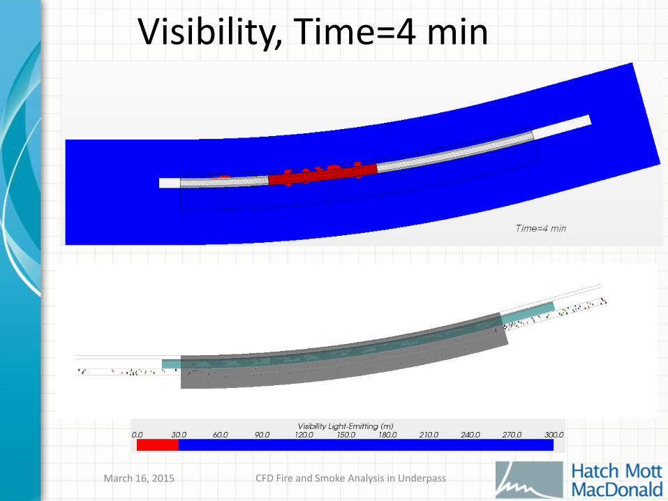
Visibility, Time=4 min
CFD Fire and Smoke Analysis in UnderpassMarch 16, 2015

Visibility, Time=4.5 min
CFD Fire and Smoke Analysis in UnderpassMarch 16, 2015

Visibility, Time=5 min
CFD Fire and Smoke Analysis in UnderpassMarch 16, 2015

Visibility, Time=5.5 and 6 min
Windows break at 5.7 min
CFD Fire and Smoke Analysis in UnderpassMarch 16, 2015

Visibility, Time=6.5 and 7 min
CFD Fire and Smoke Analysis in UnderpassMarch 16, 2015

Visibility, Time=7.5 and 8 min
CFD Fire and Smoke Analysis in UnderpassMarch 16, 2015

Animation of AnalysisCFD Data integrated with STEPS
CFD Fire and Smoke Analysis in UnderpassMarch 16, 2015

CONCLUSIONS
CFD Model of Underpass built using STAR-CCM+ and analysis done using Fire and Smoke Wizard
Visibility plots generated in the analysis
Egress analysis performed shows that passengers evacuate to safety without the need for any additional mechanical ventilation
CFD Fire and Smoke Analysis in UnderpassMarch 16, 2015

Acknowledgements
• Kenneth Li – for performing the ‘STEPS’ analysis for the study
CFD Fire and Smoke Analysis in UnderpassMarch 16, 2015

QUESTIONS?
CFD Fire and Smoke Analysis in UnderpassMarch 16, 2015

APPENDIX

Geometry details
• Proposed length of covered Section 270 ft increased to 316 ft
• Height of Underpass reduced from 18.5 ft to 16.75 ft
• Width of Underpass is 32 ft
• Gradient is -0.02% (North portal lower than South portal)
• Train floor is 1.5 ft above Underpass floor
• Top of Rail is 9” above Underpass floor


![Fire and Smoke Update]](https://img.pdfslide.net/doc/110x75/540304fadab5caf82c8b4938/fire-and-smoke-update.jpg)
