Embed Size (px)
Citation preview
FIRE DETECTION AND ALARM SYSTEMSfor
Lancashire County Council.
Presented by
Mike Turner
ECA Fire and Security Sector
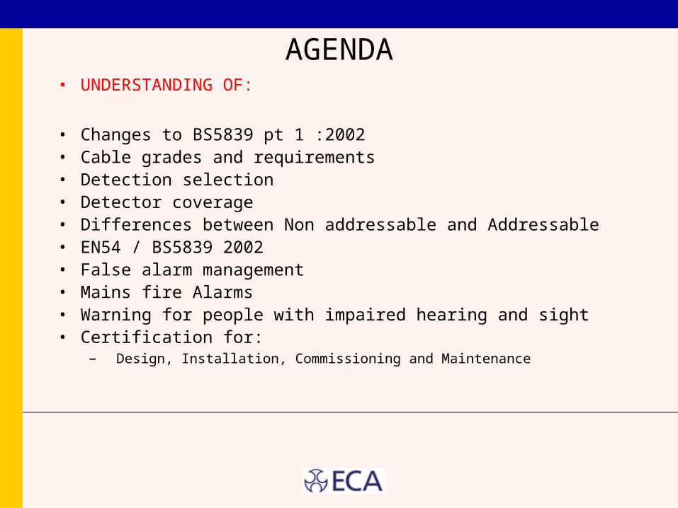
AGENDA• UNDERSTANDING OF:
• Changes to BS5839 pt 1 :2002• Cable grades and requirements• Detection selection• Detector coverage• Differences between Non addressable and Addressable• EN54 / BS5839 2002• False alarm management• Mains fire Alarms• Warning for people with impaired hearing and sight• Certification for:
– Design, Installation, Commissioning and Maintenance
Change to BS 5839 PT 1: 2002
CATEGORIES
• Categories previously known as Types• Designer alone can not select Categories• Risk Assessment
End userbuilding Control / Fire OfficerDesignerInsurance
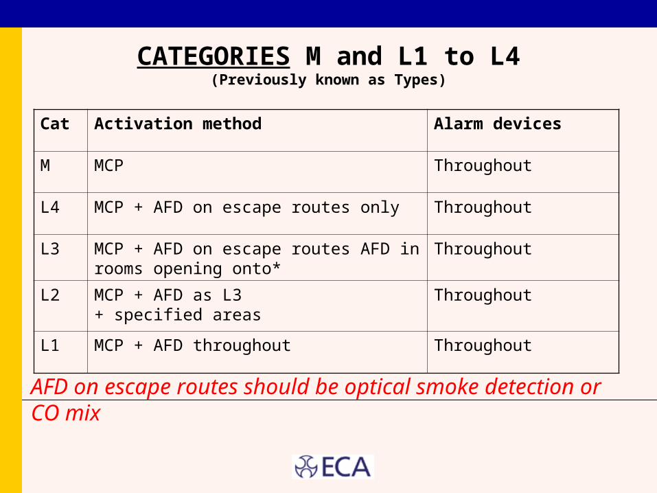
CATEGORIES M and L1 to L4(Previously known as Types)
Cat Activation method Alarm devices
M MCP Throughout
L4 MCP + AFD on escape routes only Throughout
L3 MCP + AFD on escape routes AFD in rooms opening onto*
Throughout
L2 MCP + AFD as L3+ specified areas
Throughout
L1 MCP + AFD throughout Throughout
AFD on escape routes should be optical smoke detection or CO mix
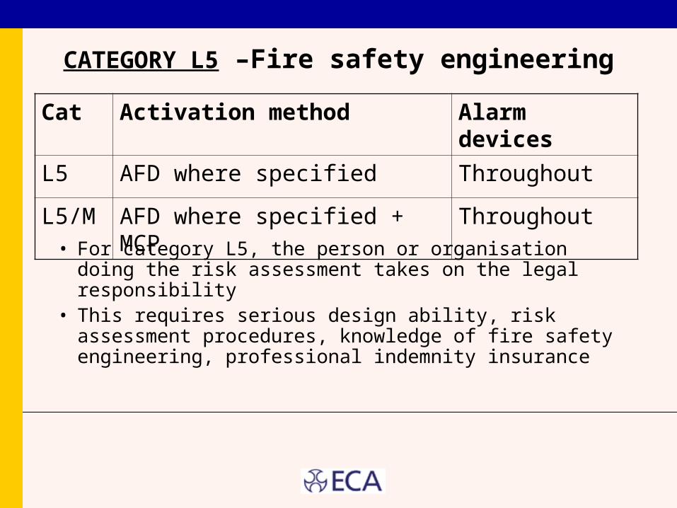
CATEGORY L5 –Fire safety engineering
• For category L5, the person or organisation doing the risk assessment takes on the legal responsibility
• This requires serious design ability, risk assessment procedures, knowledge of fire safety engineering, professional indemnity insurance
Cat Activation method Alarm devices
L5 AFD where specified Throughout
L5/M AFD where specified + MCP Throughout
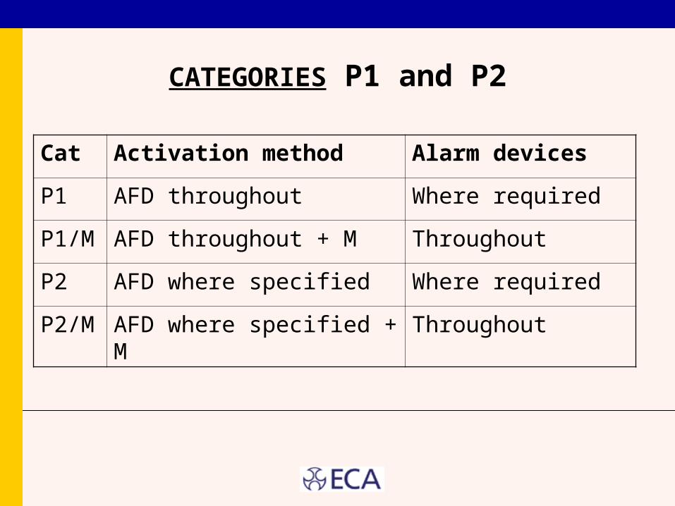
CATEGORIES P1 and P2
Cat Activation method Alarm devices
P1 AFD throughout Where required
P1/M AFD throughout + M Throughout
P2 AFD where specified Where required
P2/M AFD where specified + M Throughout
COMMUNICATIONS WITHTHE FIRE SERVICE
• Designer to ascertain if automatic comms required• For Cat P, Communications recommended unless
continuously occupied• BS 5979 for ARC• Communication unit to be protected by AFD• Communication cables routed through:
– Areas of low fire risk; OR– Areas protected by AFD or extinguishing; OR– Using fire resistant cables
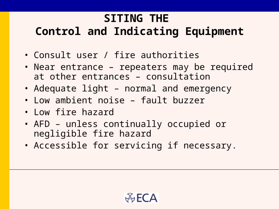
SITING THE Control and Indicating Equipment
• Consult user / fire authorities• Near entrance – repeaters may be required at other
entrances – consultation• Adequate light – normal and emergency• Low ambient noise – fault buzzer• Low fire hazard• AFD – unless continually occupied or negligible fire
hazard• Accessible for servicing if necessary.
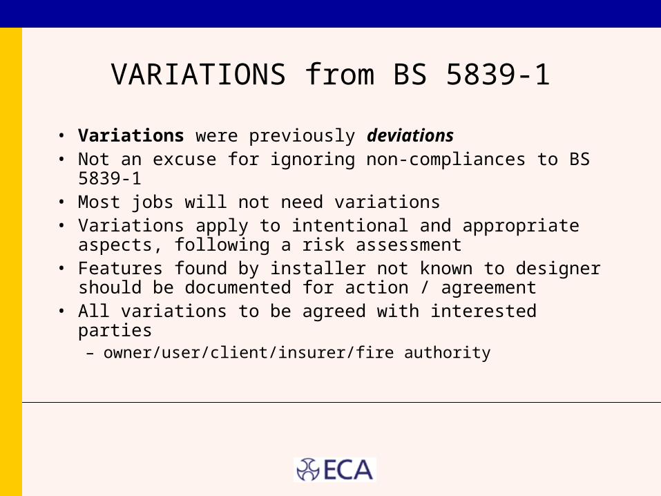
VARIATIONS from BS 5839-1
• Variations were previously deviations• Not an excuse for ignoring non-compliances to BS 5839-1• Most jobs will not need variations• Variations apply to intentional and appropriate aspects,
following a risk assessment• Features found by installer not known to designer should
be documented for action / agreement• All variations to be agreed with interested parties
– owner/user/client/insurer/fire authority
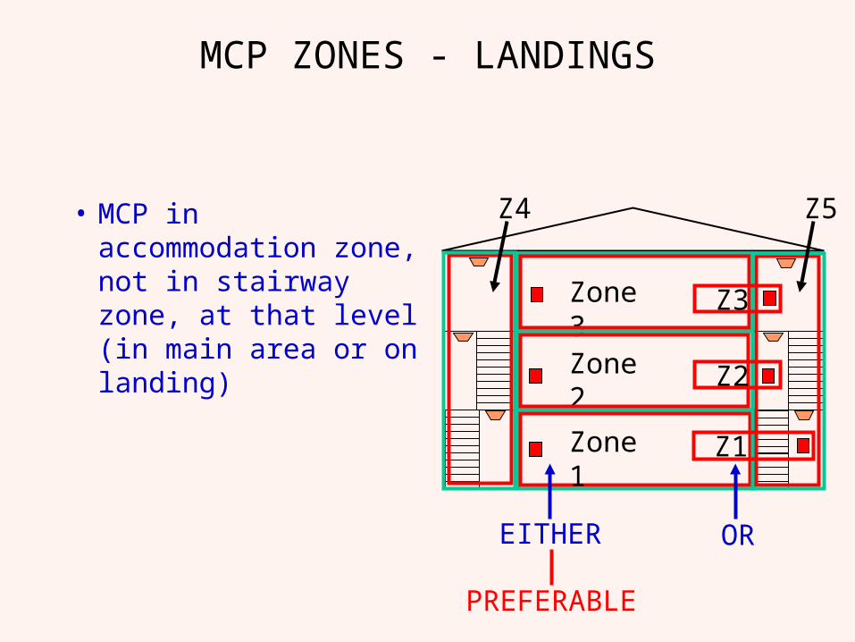
MCP ZONES - LANDINGS
• MCP in accommodation zone, not in stairway zone, at that level (in main area or on landing)
Zone 2
Zone 3
Z4 Z5
Zone 1 Z1
Z2
Z3
EITHER OR
PREFERABLE
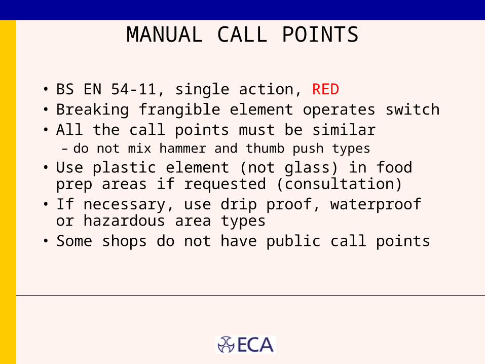
MANUAL CALL POINTS
• BS EN 54-11, single action, RED• Breaking frangible element operates switch• All the call points must be similar
– do not mix hammer and thumb push types
• Use plastic element (not glass) in food prep areas if requested (consultation)
• If necessary, use drip proof, waterproof or hazardous area types
• Some shops do not have public call points
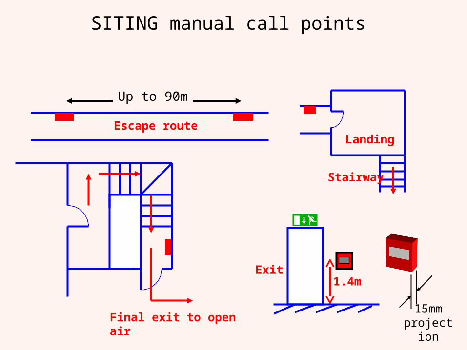
SITING manual call points
Final exit to open air
Landing
Stairway
1.4mExit
15mm projection
Escape route
Up to 90m
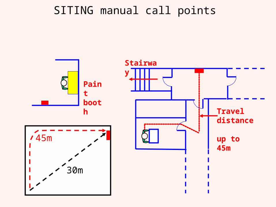
SITING manual call points
Paint booth
45m
30m
Travel distance up to 45m
Stairway
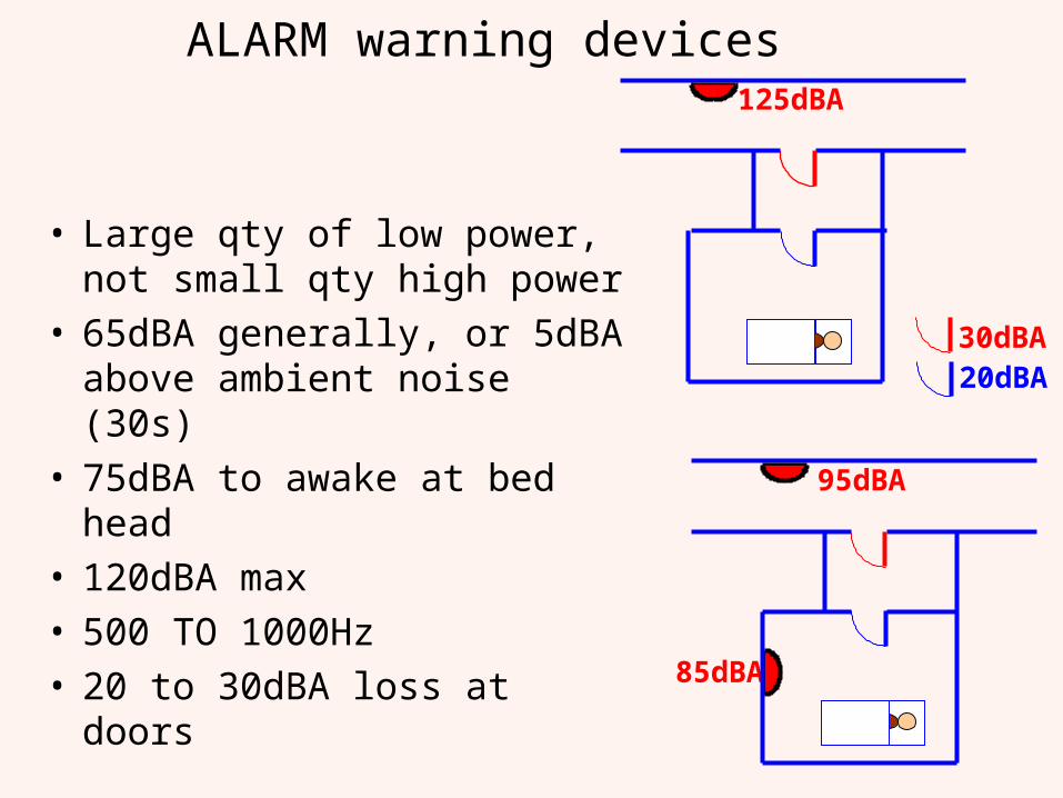
ALARM warning devices
• Large qty of low power, not small qty high power
• 65dBA generally, or 5dBA above ambient noise (30s)
• 75dBA to awake at bed head• 120dBA max• 500 TO 1000Hz• 20 to 30dBA loss at doors
20dBA30dBA
125dBA
85dBA
95dBA
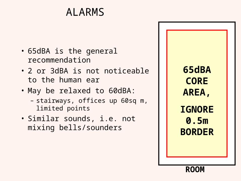
ALARMS
• 65dBA is the general recommendation
• 2 or 3dBA is not noticeable to the human ear
• May be relaxed to 60dBA:– stairways, offices up 60sq m,
limited points
• Similar sounds, i.e. not mixing bells/sounders
65dBA CORE AREA,
IGNORE 0.5m
BORDER
ROOM
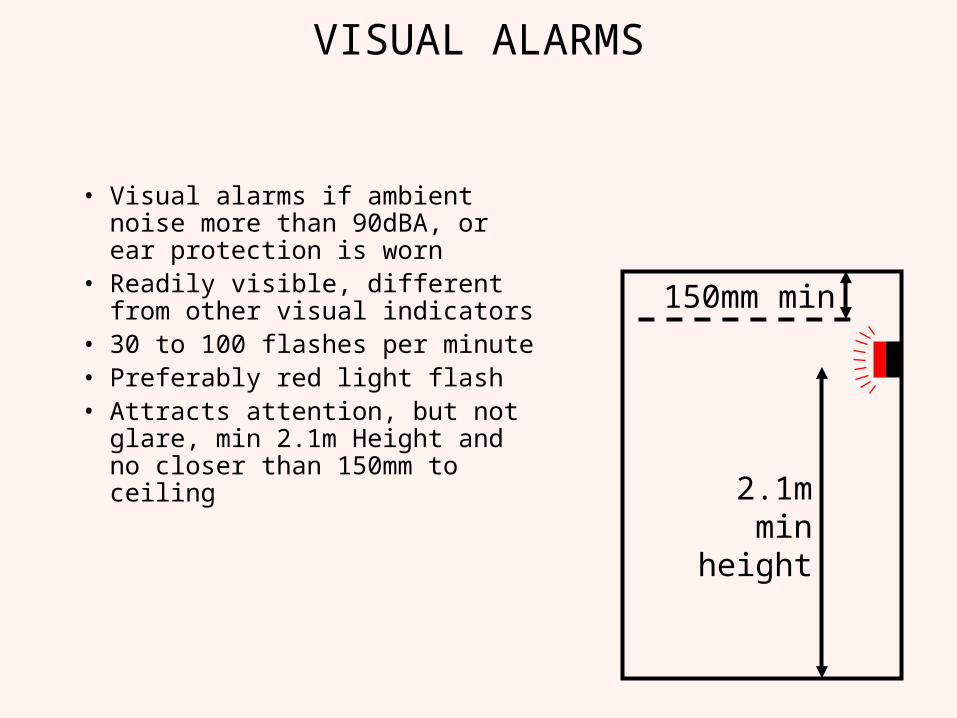
VISUAL ALARMS
• Visual alarms if ambient noise more than 90dBA, or ear protection is worn
• Readily visible, different from other visual indicators
• 30 to 100 flashes per minute• Preferably red light flash• Attracts attention, but not
glare, min 2.1m Height and no closer than 150mm to ceiling
2.1mmin
height
150mm min
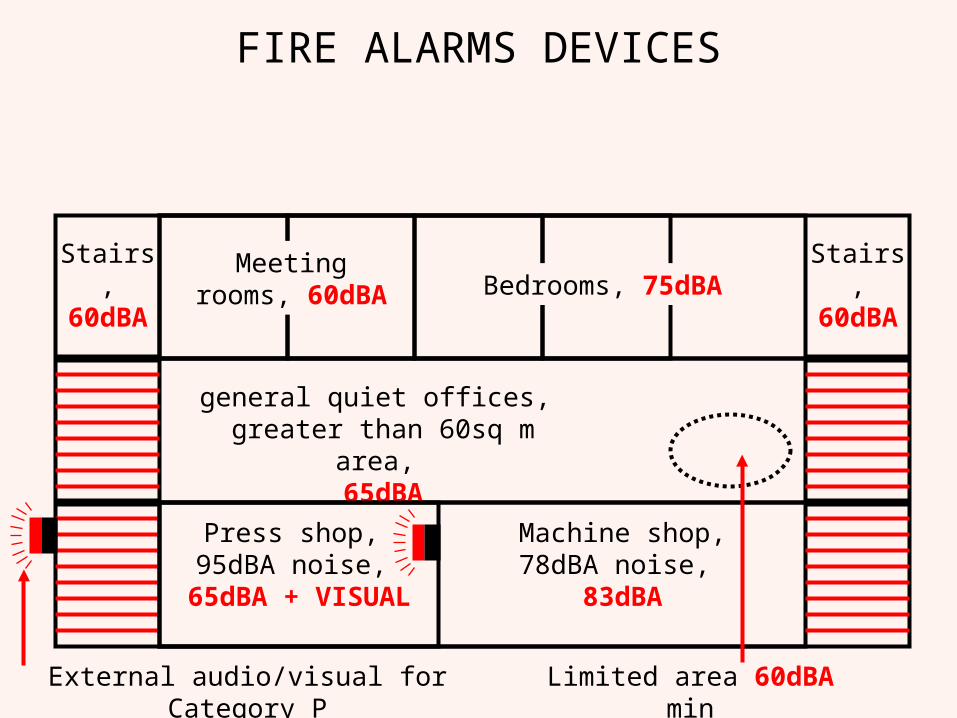
FIRE ALARMS DEVICES
Meeting rooms, 60dBA Bedrooms, 75dBA
general quiet offices, greater than 60sq m area,
65dBA
Limited area 60dBA min
Press shop, 95dBA noise,
65dBA + VISUAL
Machine shop, 78dBA noise, 83dBA
Stairs,60dBA
Stairs,60dBA
External audio/visual for Category P
Cable grades and requirements
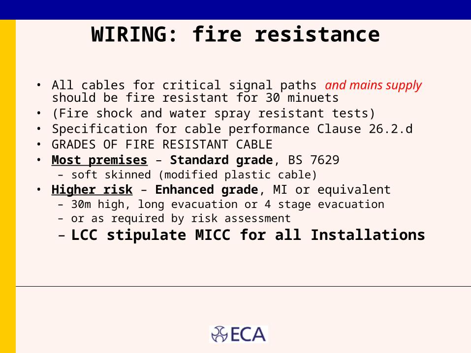
WIRING: fire resistance
• All cables for critical signal paths and mains supply should be fire resistant for 30 minuets
• (Fire shock and water spray resistant tests)• Specification for cable performance Clause 26.2.d• GRADES OF FIRE RESISTANT CABLE• Most premises – Standard grade, BS 7629
– soft skinned (modified plastic cable)• Higher risk – Enhanced grade, MI or equivalent
– 30m high, long evacuation or 4 stage evacuation– or as required by risk assessment
– LCC stipulate MICC for all Installations
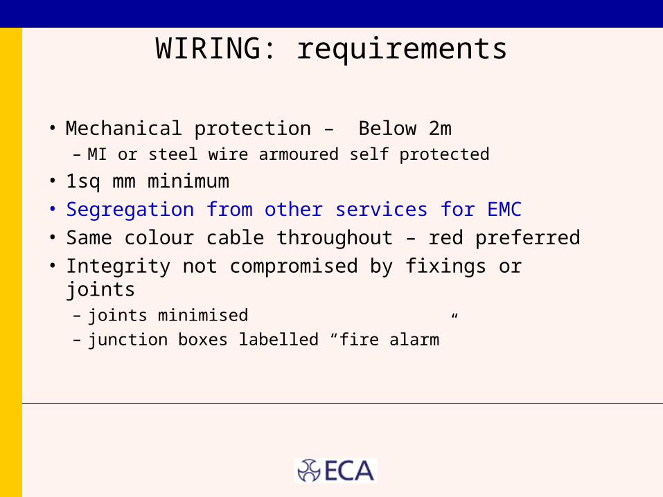
WIRING: requirements
• Mechanical protection – Below 2m – MI or steel wire armoured self protected
• 1sq mm minimum• Segregation from other services for EMC• Same colour cable throughout – red preferred• Integrity not compromised by fixings or joints
– joints minimised– junction boxes labelled “fire alarm”
Detector selection
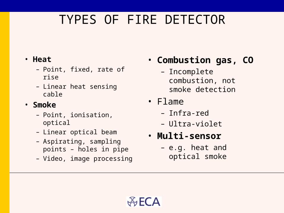
TYPES OF FIRE DETECTOR
• Heat– Point, fixed, rate of rise– Linear heat sensing
cable
• Smoke– Point, ionisation, optical– Linear optical beam– Aspirating, sampling
points – holes in pipe– Video, image processing
• Combustion gas, CO– Incomplete combustion,
not smoke detection
• Flame– Infra-red– Ultra-violet
• Multi-sensor– e.g. heat and optical
smoke
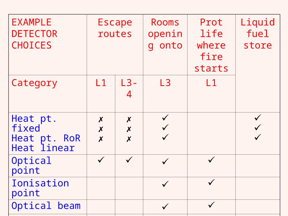
EXAMPLE DETECTOR CHOICES
Escape routes
Rooms opening
onto
Prot life where fire
starts
Liquid fuel
store
Category L1 L3-4 L3 L1
Heat pt. fixedHeat pt. RoRHeat linear
Optical point Ionisation point Optical beam CO mix mix Aspirating Flame
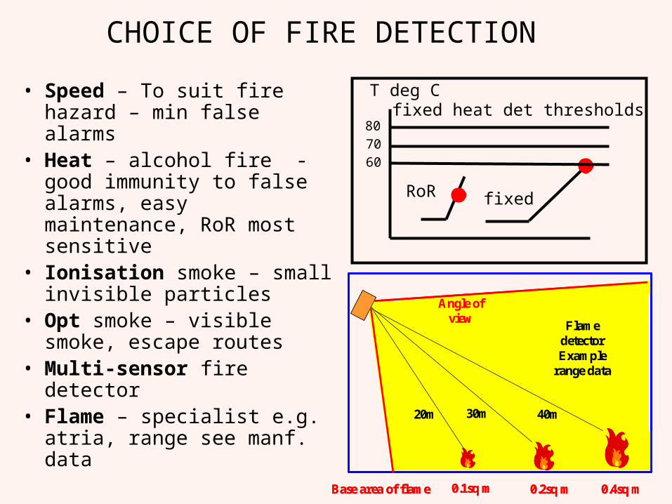
CHOICE OF FIRE DETECTION
• Speed – To suit fire hazard – min false alarms
• Heat – alcohol fire - good immunity to false alarms, easy maintenance, RoR most sensitive
• Ionisation smoke – small invisible particles
• Opt smoke – visible smoke, escape routes
• Multi-sensor fire detector• Flame – specialist e.g. atria,
range see manf. data 40m
Base area of flame
Flame detectorExample
range data
30m20m
Angle of view
0.1sq m 0.2sq m 0.4sq m
40m
Base area of flame
Flame detectorExample
range data
30m20m
Angle of view
0.1sq m 0.2sq m 0.4sq m
fixedRoR
T deg Cfixed heat det thresholds
807060
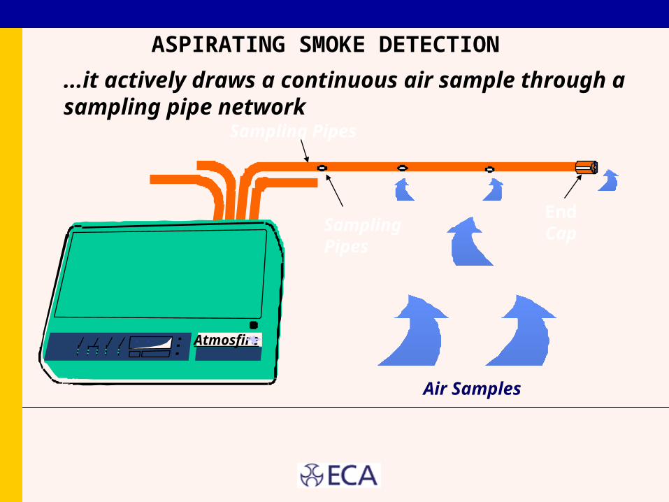
Sampling Pipes
Sampling Pipes
EndCap
Air Samples
Atmosfire
...it actively draws a continuous air sample through a sampling pipe network
ASPIRATING SMOKE DETECTION
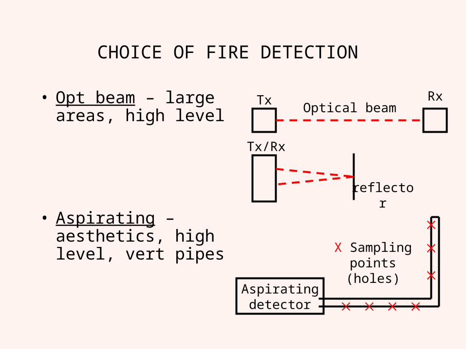
CHOICE OF FIRE DETECTION
• Opt beam – large areas, high level
• Aspirating – aesthetics, high level, vert pipes
Tx Rx
Tx/Rx
reflector
Optical beam
Aspiratingdetector
X Samplingpoints (holes)
Detector coverage
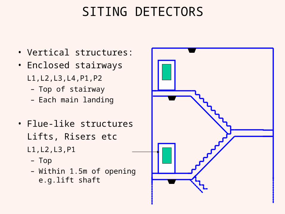
SITING DETECTORS
• Vertical structures:• Enclosed stairways
L1,L2,L3,L4,P1,P2
– Top of stairway– Each main landing
• Flue-like structures
Lifts, Risers etc
L1,L2,L3,P1
– Top– Within 1.5m of opening
e.g.lift shaft
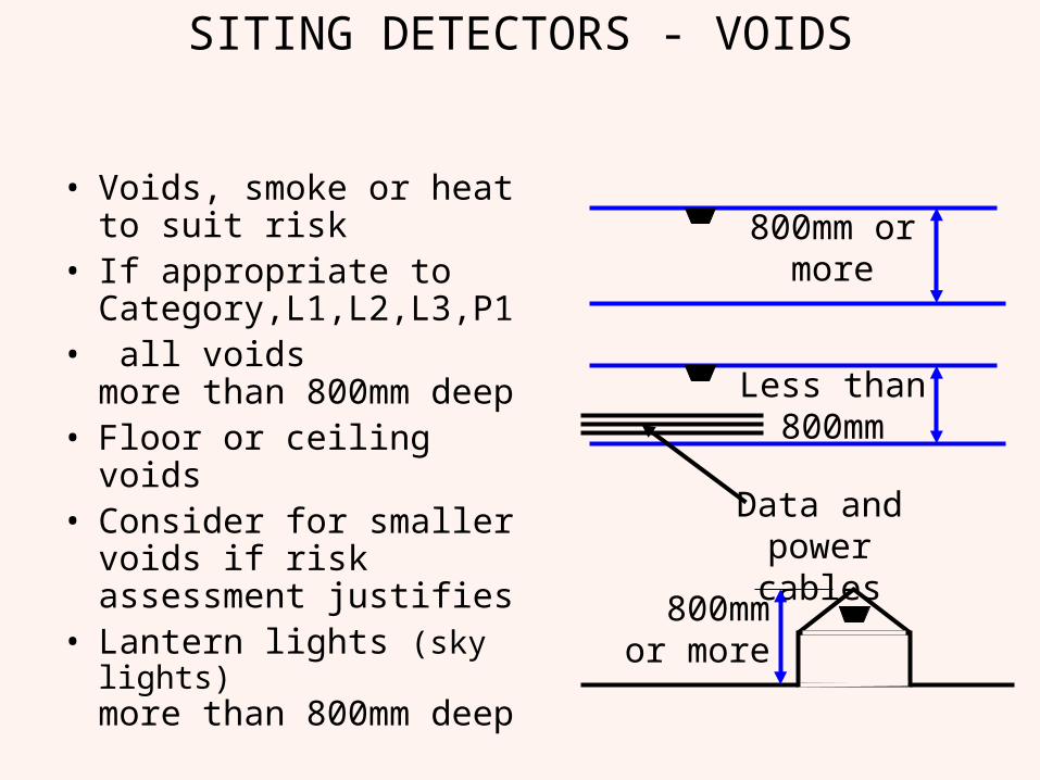
SITING DETECTORS - VOIDS
• Voids, smoke or heat to suit risk
• If appropriate to Category,L1,L2,L3,P1
• all voids more than 800mm deep
• Floor or ceiling voids• Consider for smaller voids
if risk assessment justifies• Lantern lights (sky lights)
more than 800mm deep
800mm or more
Less than 800mm
Data and power cables
800mmor more
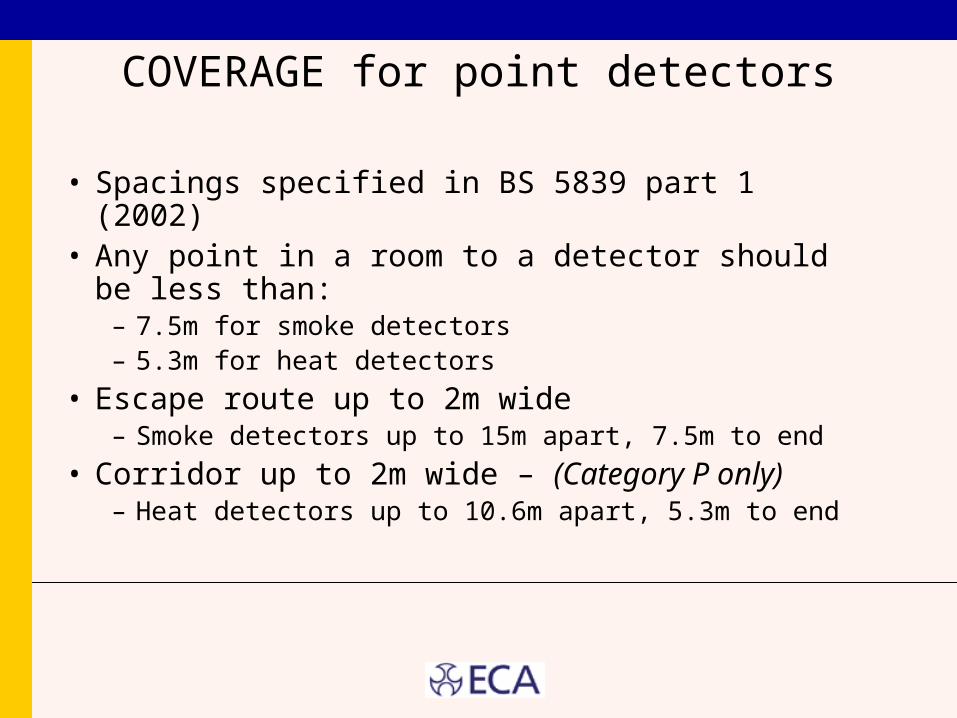
COVERAGE for point detectors
• Spacings specified in BS 5839 part 1 (2002)• Any point in a room to a detector should be less
than:– 7.5m for smoke detectors– 5.3m for heat detectors
• Escape route up to 2m wide– Smoke detectors up to 15m apart, 7.5m to end
• Corridor up to 2m wide – (Category P only)– Heat detectors up to 10.6m apart, 5.3m to end
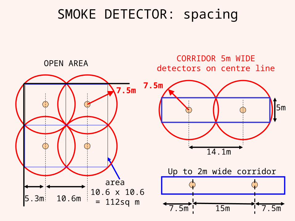
SMOKE DETECTOR: spacing
CORRIDOR 5m WIDEdetectors on centre line
5m
7.5m
14.1m
15m 7.5m7.5m
Up to 2m wide corridorarea
10.6 x 10.6= 112sq m
OPEN AREA
7.5m
10.6m5.3m
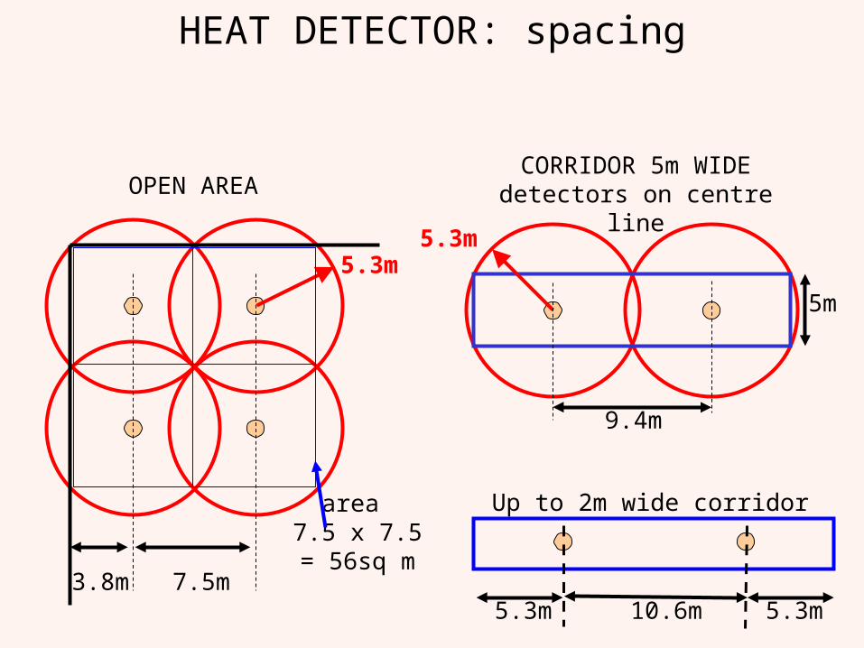
HEAT DETECTOR: spacing
5m
CORRIDOR 5m WIDEdetectors on centre line
5.3m
9.4m
area 7.5 x 7.5= 56sq m
OPEN AREA
5.3m
7.5m3.8m10.6m 5.3m5.3m
Up to 2m wide corridor
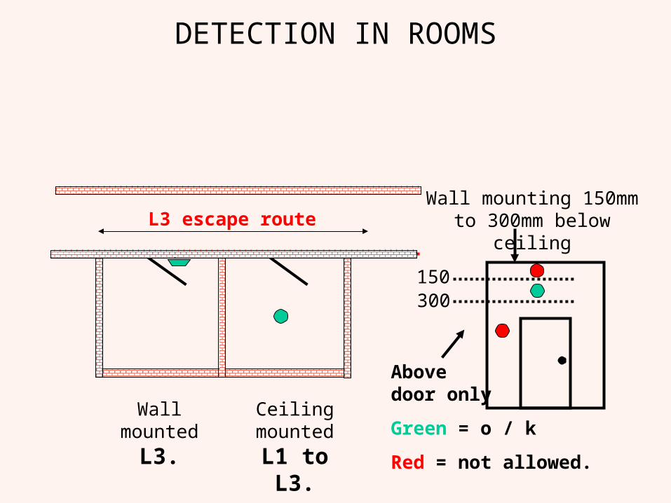
DETECTION IN ROOMS
L3 escape route
Ceiling mounted
L1 to L3.
Wall mounted
L3.
Wall mounting 150mm to 300mm below ceiling
300150
Abovedoor only
Green = o / k
Red = not allowed.
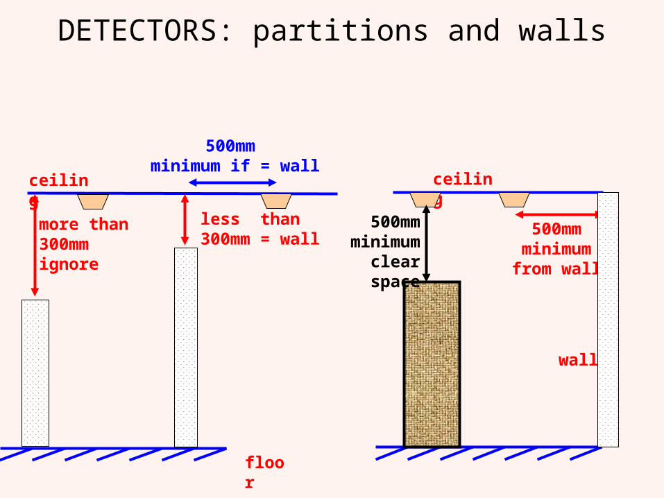
DETECTORS: partitions and walls
more than 300mm ignore
less than300mm = wall
ceiling
floor
ceiling
wall
500mm minimum from wall
500mm minimum if = wall
500mm minimum
clear space
Differences between Non addressableand
Analogue Addressable.
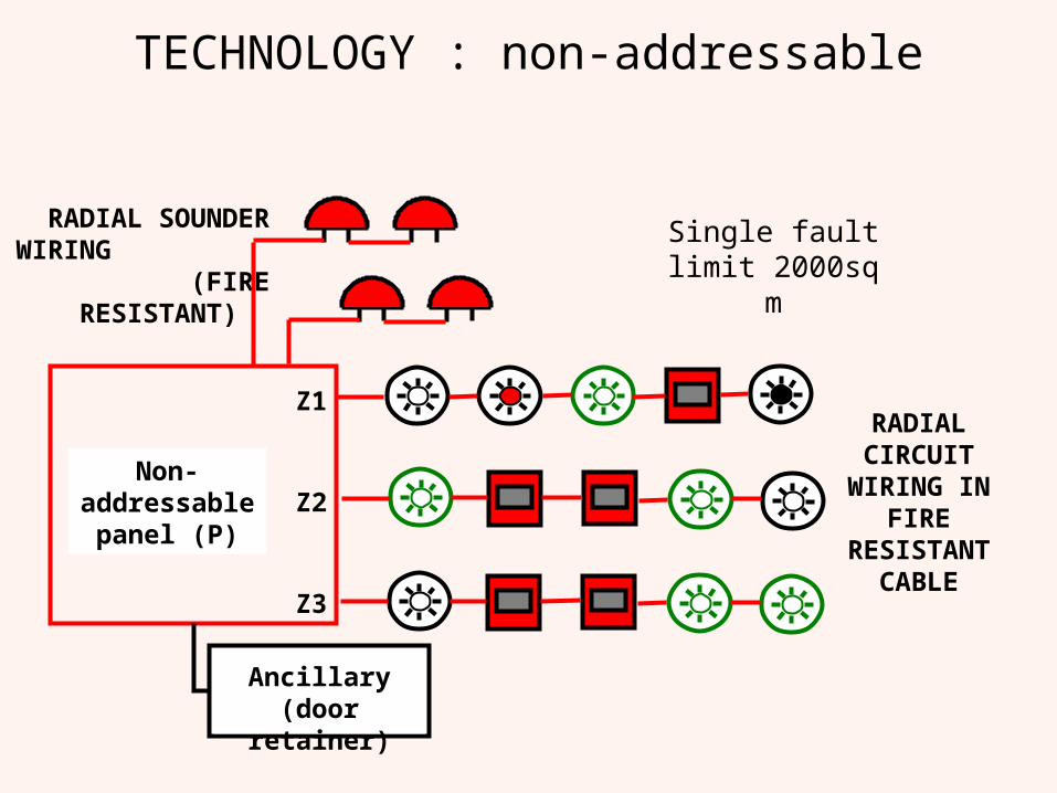
TECHNOLOGY : non-addressable
RADIAL SOUNDER WIRING
(FIRE RESISTANT)
Z1
Z2
Z3
Non-addressable
panel (P)
RADIAL CIRCUIT
WIRING IN FIRE
RESISTANT CABLE
Ancillary (door retainer)
Single fault limit 2000sq m
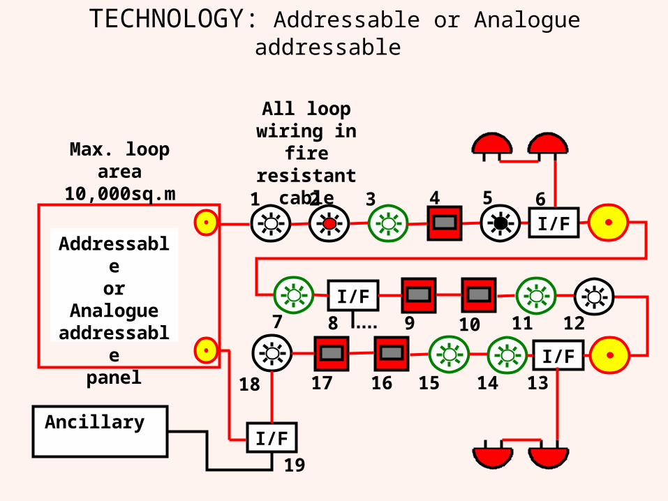
TECHNOLOGY: Addressable or Analogue addressable
I/F
All loop wiring in fire resistant
cable654321
Addressableor
Analogue addressable
panel
I/F7 8 9 10 11 12
I/F
1314151618 17
Ancillary I/F
19
Max. loop area 10,000sq.m
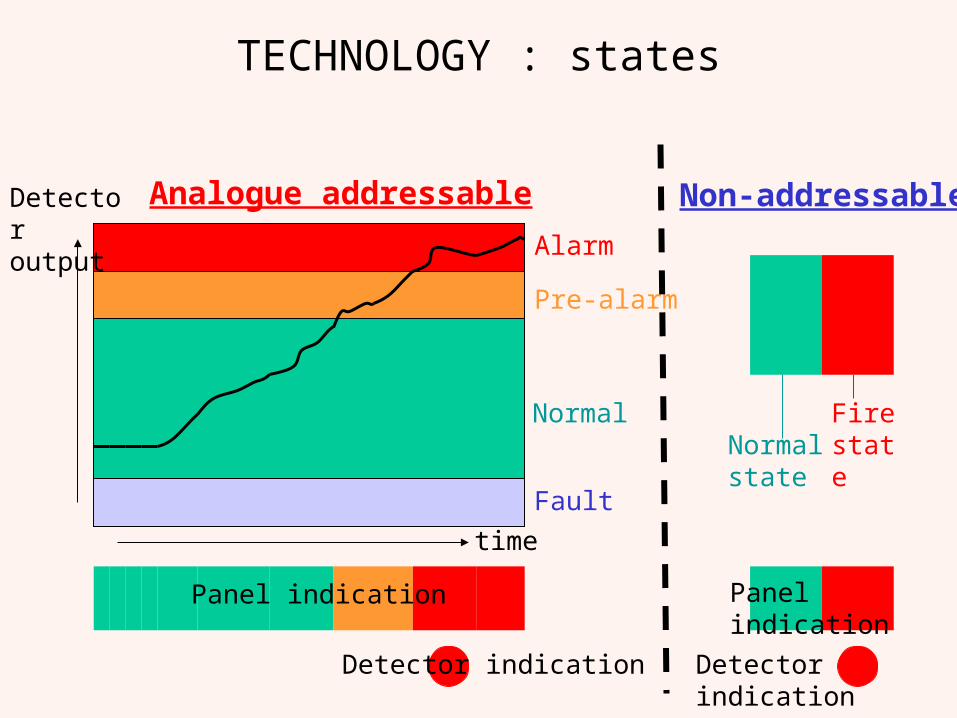
TECHNOLOGY : states
Alarm
Pre-alarm
time
Normal
Fault
Detector output
Panel indication
Analogue addressable Non-addressable
Normal state
Fire state
Panel indication
Detector indicationDetector indication
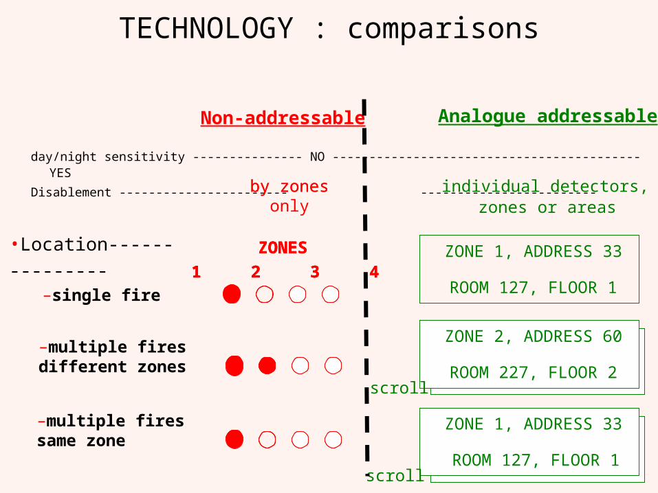
TECHNOLOGY : comparisons
day/night sensitivity --------------- NO ------------------------------------------ YES
Disablement ----------------------- ------------------------
–multiple firesdifferent zones
–multiple firessame zone
•Location---------------–single fire
by zones
ZONES
1 2 3 4
Non-addressable
by zonesonly
ZONES
1 2 3 4
ZONES
1 2 3 4
Analogue addressable
individual detectors, zones or areas
ZONE 1, ADDRESS 33
ROOM 127, FLOOR 1
ZONE 2, ADDRESS 60
ROOM 227, FLOOR 2
ZONE 1, ADDRESS 33
ROOM 127, FLOOR 1
scroll
scroll
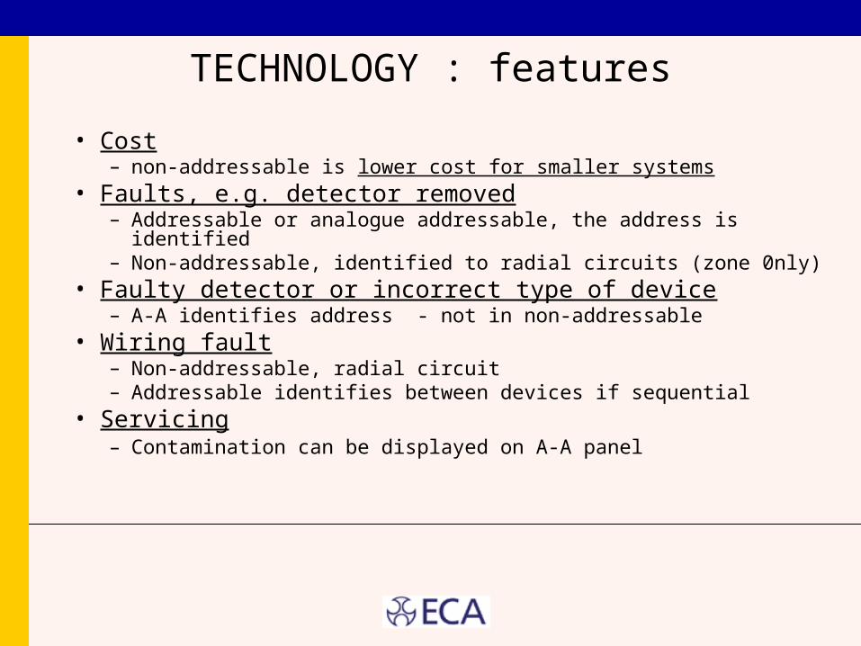
TECHNOLOGY : features
• Cost– non-addressable is lower cost for smaller systems
• Faults, e.g. detector removed– Addressable or analogue addressable, the address is identified– Non-addressable, identified to radial circuits (zone 0nly)
• Faulty detector or incorrect type of device– A-A identifies address - not in non-addressable
• Wiring fault– Non-addressable, radial circuit– Addressable identifies between devices if sequential
• Servicing– Contamination can be displayed on A-A panel
STANDARDS
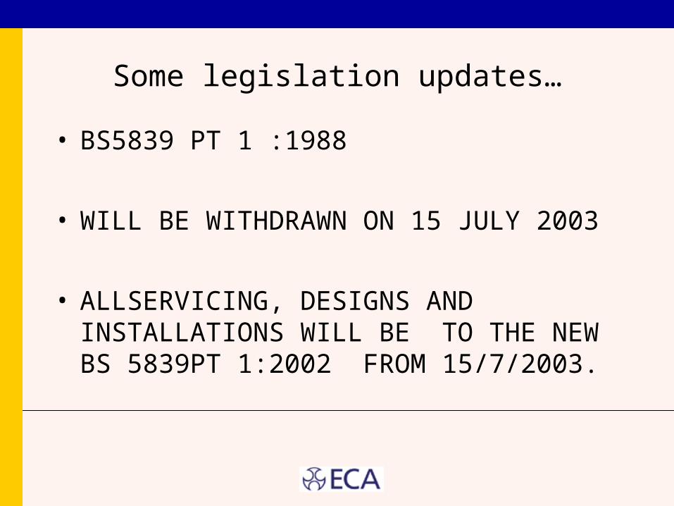
Some legislation updates…
• BS5839 PT 1 :1988
• WILL BE WITHDRAWN ON 15 JULY 2003
• ALLSERVICING, DESIGNS AND INSTALLATIONS WILL BE TO THE NEW BS 5839PT 1:2002 FROM 15/7/2003.
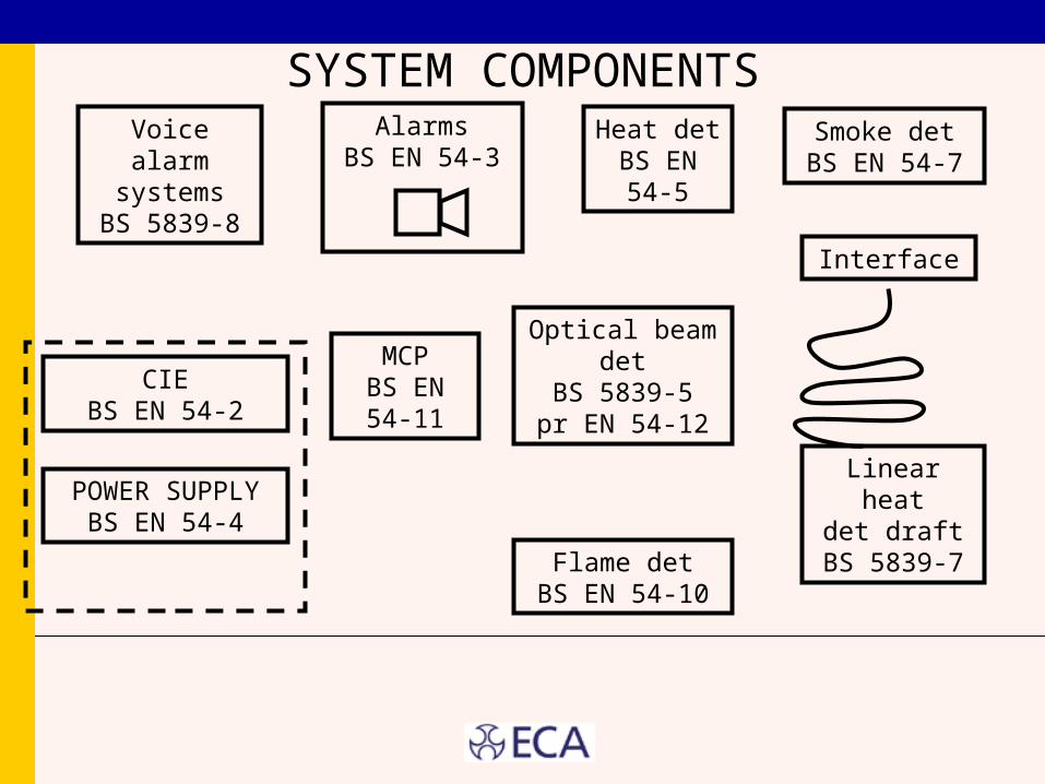
SYSTEM COMPONENTS
MCPBS EN 54-
11
Heat detBS EN 54-
5
Smoke detBS EN 54-7
Optical beam detBS 5839-5
pr EN 54-12
Flame detBS EN 54-10
CIEBS EN 54-2
POWER SUPPLYBS EN 54-4
Linear heatdet draft
BS 5839-7
Interface
AlarmsBS EN 54-3
Voice alarm systems
BS 5839-8
False Alarm Management
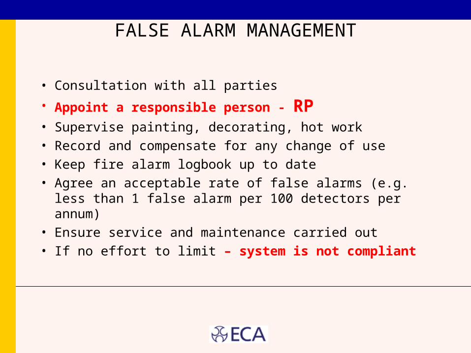
FALSE ALARM MANAGEMENT
• Consultation with all parties
• Appoint a responsible person - RP• Supervise painting, decorating, hot work
• Record and compensate for any change of use
• Keep fire alarm logbook up to date
• Agree an acceptable rate of false alarms (e.g. less than 1 false alarm per 100 detectors per annum)
• Ensure service and maintenance carried out
• If no effort to limit – system is not compliant
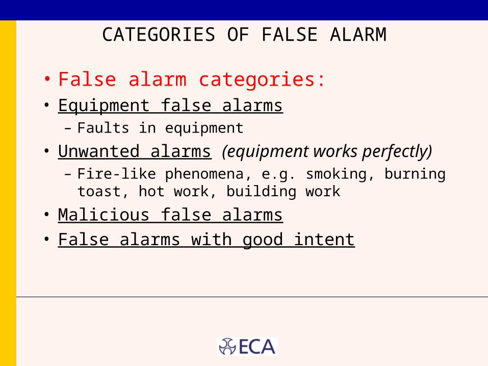
CATEGORIES OF FALSE ALARM
• False alarm categories:• Equipment false alarms
– Faults in equipment
• Unwanted alarms (equipment works perfectly)– Fire-like phenomena, e.g. smoking, burning toast, hot
work, building work
• Malicious false alarms• False alarms with good intent
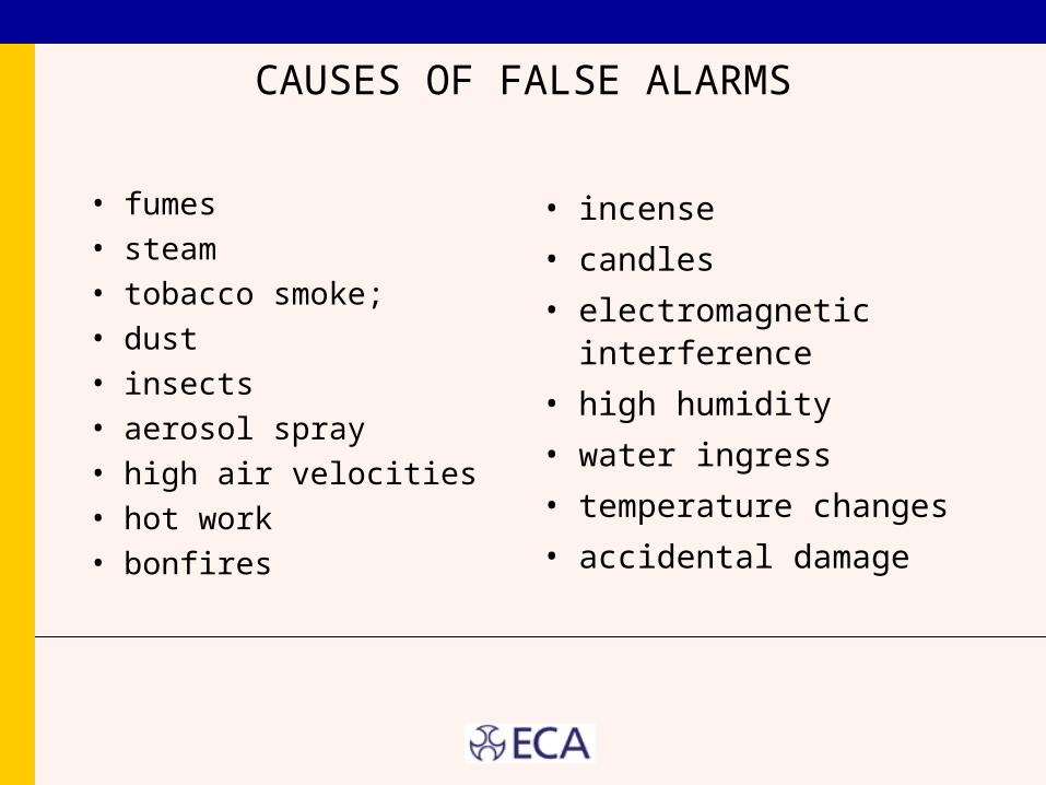
CAUSES OF FALSE ALARMS
• fumes• steam• tobacco smoke;• dust• insects• aerosol spray• high air velocities• hot work• bonfires
• incense
• candles
• electromagnetic interference
• high humidity
• water ingress
• temperature changes
• accidental damage
FALSE ALARMS (SEC35.2.6)
• Systems with 50 or more devices require a 1 week soak test (defined by the Designer and built into the Tender).
• If it False Alarm’s then identify the Alarm, rectify it and start the 1 week soak test again -------
• Until successful the system should not be regarded as an operational means of giving warning of a fire in the building. During this soak all MAC’S should bear an indication that it is not to be used. When all clear carry out the final hand over.
Mains fire Alarms and the Law
MAINTENANCE and the LAW
• Fire Precautions (Workplace) Regulations require a system of maintenance
• Systems with no battery backup are not legal– Competent Person should advise users to replace urgently
• Failure to keep the fire detection and alarms in good working order is a criminal offence
• Arranging a suitable system of maintenance is so easy to do, that neglecting to do it is blatant flouting of the law.
The HEALTH & SAFETY(SAFETY SIGNS & SIGNALS) REGULATIONS (1996)
• Require that fire alarm warning systems must be provided with a guaranteed emergency supply in the event of a power cut, unless the hazard has been eliminated.
• This means that systems not having a standby power supply (battery back up) are no longer legal.
• This is also a law, failure to comply being an offence.
MAINTENANCE - Non Routine Attention
• Special inspection on appointment of new
service company
• Attendance available 24/7 within 8h
• Tests following modifications
• Action to address unacceptable false alarms
• Tests following long periods of disconnection
Fire Alarms Warnings
BS5839 PT 1 :2002 (sec18.1&2)
• If people are moving freely around the building then visual indication preferably RED should be installed in all necessary places, and associated toilets.
• Caution consider photosensitive epileptics when using strobes.
• If they are sleeping in the building then tactile devices may be required. For example placed under a pillow wired into the fire alarm circuit.
• Other options may be vibrating pagers.

CERTIFICATION
DOCUMENTATION AND CERTIFICATION
• Documentation
• Installation Certificate
• Commissioning certificate
• Acceptance Certificate
• Verification certificate (optional)
• Maintenance Certificate

End of presentation.