Embed Size (px)
Citation preview
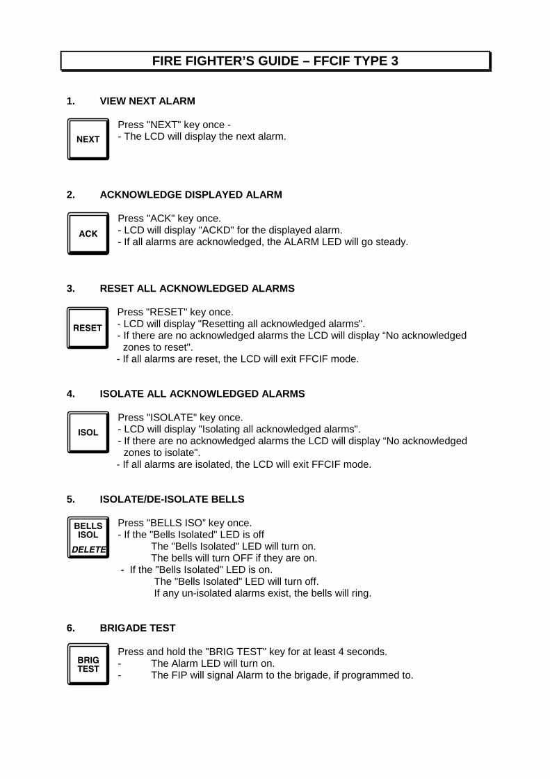
FIRE FIGHTER’S GUIDE – FFCIF TYPE 3
1. VIEW NEXT ALARM
Press "NEXT" key once -- The LCD will display the next alarm.
2. ACKNOWLEDGE DISPLAYED ALARM
Press "ACK" key once.- LCD will display "ACKD" for the displayed alarm.- If all alarms are acknowledged, the ALARM LED will go steady.
3. RESET ALL ACKNOWLEDGED ALARMS
Press "RESET" key once.- LCD will display "Resetting all acknowledged alarms".- If there are no acknowledged alarms the LCD will display “No acknowledged zones to reset".- If all alarms are reset, the LCD will exit FFCIF mode.
4. ISOLATE ALL ACKNOWLEDGED ALARMS
Press "ISOLATE" key once.- LCD will display "Isolating all acknowledged alarms".- If there are no acknowledged alarms the LCD will display “No acknowledged zones to isolate".- If all alarms are isolated, the LCD will exit FFCIF mode.
5. ISOLATE/DE-ISOLATE BELLS
Press "BELLS ISO” key once.- If the "Bells Isolated" LED is off
The "Bells Isolated" LED will turn on.The bells will turn OFF if they are on.
- If the "Bells Isolated" LED is on.The "Bells Isolated" LED will turn off.If any un-isolated alarms exist, the bells will ring.
6. BRIGADE TEST
Press and hold the "BRIG TEST" key for at least 4 seconds.- The Alarm LED will turn on.- The FIP will signal Alarm to the brigade, if programmed to.
VIGILANTFire and Evacuation Systems
REMOTE DISPLAY UNIT (RDU)
OPERATOR'S MANUAL
Document Number: LT0133
Issue ......... 2.02; 21 August 2000
-- A P P R O V A L S --AUSTRALIAN STANDARDS AS1603.4 1987 (Incl. Amdt 1 & 2):AUSTRALIAN STANDARDS AS4050(INT) 1992AUSTRALIAN/NZ STANDARD AS/NZS3548 1995 Class ANEW ZEALAND STANDARD NZS4512 1994
The RDU is manufactured by:
Vigilant Fire & Evacuation Systems211 Maces Road
ChristchurchNEW ZEALAND
Tel : +64-3-389-5096Fax : +64-3-389-5938
COPYRIGHT (C) 2000
Information contained in this document is subject to copyright, and shall not be reproducedin any form whatsoever, without the written consent of Vigilant Fire & Evacuation Systems.
Information contained in this document is believed to be accurate and reliable, howeverVigilant Fire & Evacuation Systems reserves the right to change the content without priornotice.
RDU Operator's Manual Document No: LT0133
Page ii 21 August 2000 Issue 2.02
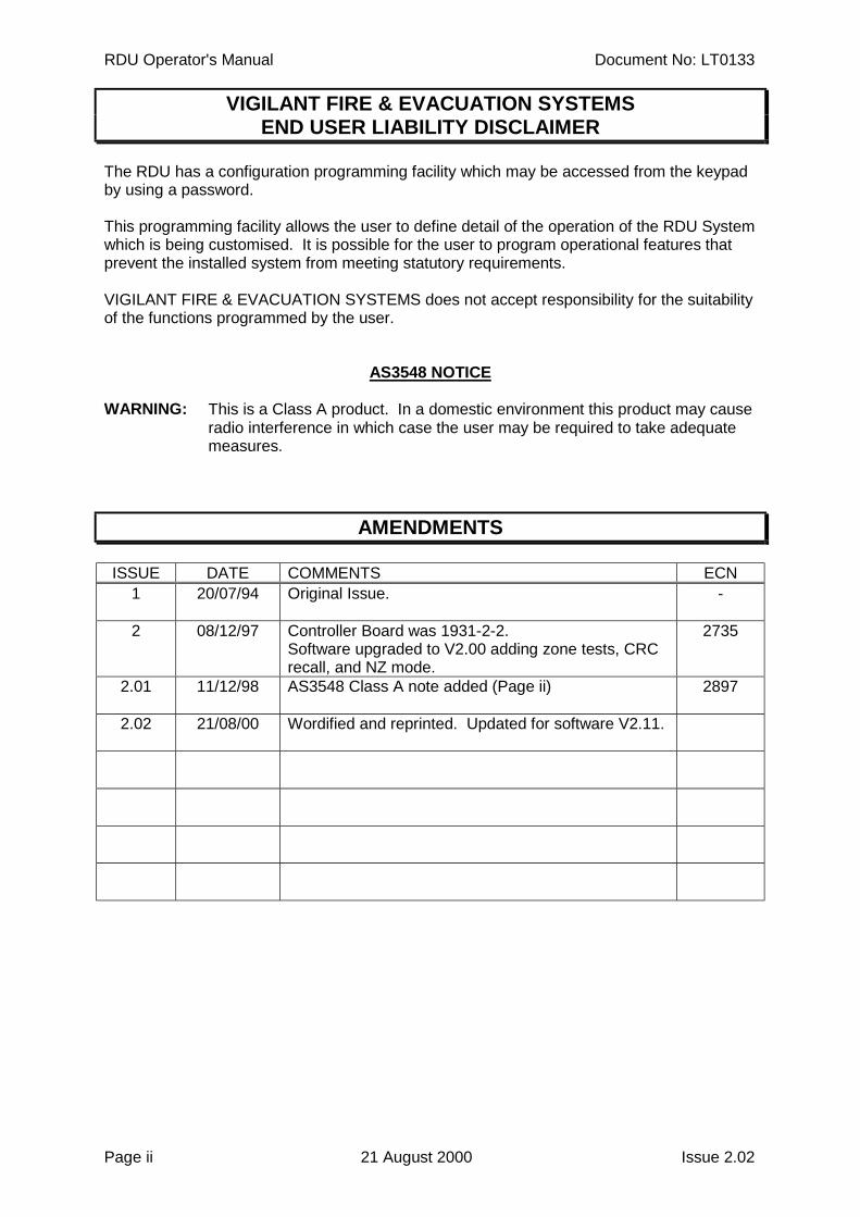
VIGILANT FIRE & EVACUATION SYSTEMSEND USER LIABILITY DISCLAIMER
The RDU has a configuration programming facility which may be accessed from the keypadby using a password.
This programming facility allows the user to define detail of the operation of the RDU Systemwhich is being customised. It is possible for the user to program operational features thatprevent the installed system from meeting statutory requirements.
VIGILANT FIRE & EVACUATION SYSTEMS does not accept responsibility for the suitabilityof the functions programmed by the user.
AS3548 NOTICE
WARNING: This is a Class A product. In a domestic environment this product may causeradio interference in which case the user may be required to take adequatemeasures.
AMENDMENTS
ISSUE DATE COMMENTS ECN1 20/07/94 Original Issue. -
2 08/12/97 Controller Board was 1931-2-2.Software upgraded to V2.00 adding zone tests, CRCrecall, and NZ mode.
2735
2.01 11/12/98 AS3548 Class A note added (Page ii) 2897
2.02 21/08/00 Wordified and reprinted. Updated for software V2.11.
Document No: LT0133 RDU Operator's Manual
Issue 2.02 21 August 2000 Page iii
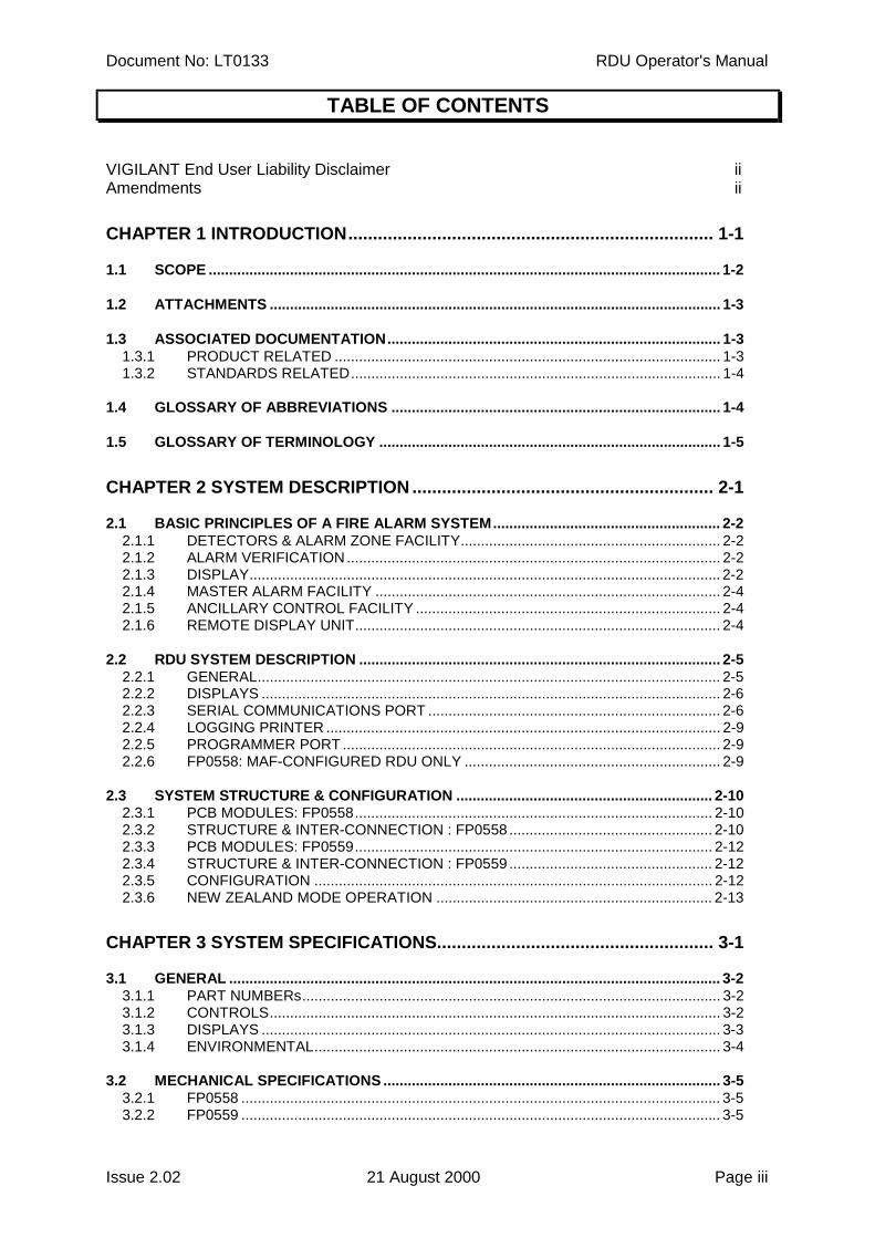
TABLE OF CONTENTS
VIGILANT End User Liability Disclaimer iiAmendments ii
CHAPTER 1 INTRODUCTION.......................................................................... 1-1
1.1 SCOPE .............................................................................................................................. 1-2
1.2 ATTACHMENTS ............................................................................................................... 1-3
1.3 ASSOCIATED DOCUMENTATION.................................................................................. 1-31.3.1 PRODUCT RELATED ............................................................................................... 1-31.3.2 STANDARDS RELATED........................................................................................... 1-4
1.4 GLOSSARY OF ABBREVIATIONS ................................................................................. 1-4
1.5 GLOSSARY OF TERMINOLOGY .................................................................................... 1-5
CHAPTER 2 SYSTEM DESCRIPTION ............................................................. 2-1
2.1 BASIC PRINCIPLES OF A FIRE ALARM SYSTEM........................................................ 2-22.1.1 DETECTORS & ALARM ZONE FACILITY................................................................ 2-22.1.2 ALARM VERIFICATION............................................................................................ 2-22.1.3 DISPLAY.................................................................................................................... 2-22.1.4 MASTER ALARM FACILITY ..................................................................................... 2-42.1.5 ANCILLARY CONTROL FACILITY ........................................................................... 2-42.1.6 REMOTE DISPLAY UNIT.......................................................................................... 2-4
2.2 RDU SYSTEM DESCRIPTION ......................................................................................... 2-52.2.1 GENERAL.................................................................................................................. 2-52.2.2 DISPLAYS ................................................................................................................. 2-62.2.3 SERIAL COMMUNICATIONS PORT ........................................................................ 2-62.2.4 LOGGING PRINTER ................................................................................................. 2-92.2.5 PROGRAMMER PORT ............................................................................................. 2-92.2.6 FP0558: MAF-CONFIGURED RDU ONLY ............................................................... 2-9
2.3 SYSTEM STRUCTURE & CONFIGURATION ............................................................... 2-102.3.1 PCB MODULES: FP0558........................................................................................ 2-102.3.2 STRUCTURE & INTER-CONNECTION : FP0558 .................................................. 2-102.3.3 PCB MODULES: FP0559........................................................................................ 2-122.3.4 STRUCTURE & INTER-CONNECTION : FP0559 .................................................. 2-122.3.5 CONFIGURATION .................................................................................................. 2-122.3.6 NEW ZEALAND MODE OPERATION .................................................................... 2-13
CHAPTER 3 SYSTEM SPECIFICATIONS........................................................ 3-1
3.1 GENERAL ......................................................................................................................... 3-23.1.1 PART NUMBERs....................................................................................................... 3-23.1.2 CONTROLS............................................................................................................... 3-23.1.3 DISPLAYS ................................................................................................................. 3-33.1.4 ENVIRONMENTAL.................................................................................................... 3-4
3.2 MECHANICAL SPECIFICATIONS ................................................................................... 3-53.2.1 FP0558 ...................................................................................................................... 3-53.2.2 FP0559 ...................................................................................................................... 3-5
RDU Operator's Manual Document No: LT0133
Page iv 21 August 2000 Issue 2.02
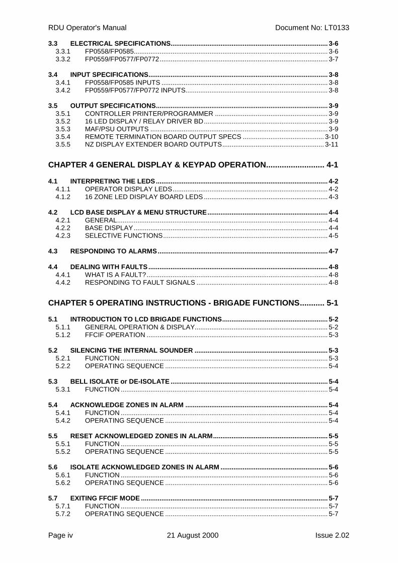
3.3 ELECTRICAL SPECIFICATIONS..................................................................................... 3-63.3.1 FP0558/FP0585......................................................................................................... 3-63.3.2 FP0559/FP0577/FP0772........................................................................................... 3-7
3.4 INPUT SPECIFICATIONS................................................................................................. 3-83.4.1 FP0558/FP0585 INPUTS .......................................................................................... 3-83.4.2 FP0559/FP0577/FP0772 INPUTS............................................................................. 3-8
3.5 OUTPUT SPECIFICATIONS............................................................................................. 3-93.5.1 CONTROLLER PRINTER/PROGRAMMER ............................................................. 3-93.5.2 16 LED DISPLAY / RELAY DRIVER BD................................................................... 3-93.5.3 MAF/PSU OUTPUTS ................................................................................................ 3-93.5.4 REMOTE TERMINATION BOARD OUTPUT SPECS ............................................ 3-103.5.5 NZ DISPLAY EXTENDER BOARD OUTPUTS....................................................... 3-11
CHAPTER 4 GENERAL DISPLAY & KEYPAD OPERATION.......................... 4-1
4.1 INTERPRETING THE LEDS............................................................................................. 4-24.1.1 OPERATOR DISPLAY LEDS.................................................................................... 4-24.1.2 16 ZONE LED DISPLAY BOARD LEDS ................................................................... 4-3
4.2 LCD BASE DISPLAY & MENU STRUCTURE................................................................. 4-44.2.1 GENERAL.................................................................................................................. 4-44.2.2 BASE DISPLAY......................................................................................................... 4-44.2.3 SELECTIVE FUNCTIONS......................................................................................... 4-5
4.3 RESPONDING TO ALARMS............................................................................................ 4-7
4.4 DEALING WITH FAULTS................................................................................................. 4-84.4.1 WHAT IS A FAULT?.................................................................................................. 4-84.4.2 RESPONDING TO FAULT SIGNALS ....................................................................... 4-8
CHAPTER 5 OPERATING INSTRUCTIONS - BRIGADE FUNCTIONS........... 5-1
5.1 INTRODUCTION TO LCD BRIGADE FUNCTIONS......................................................... 5-25.1.1 GENERAL OPERATION & DISPLAY........................................................................ 5-25.1.2 FFCIF OPERATION .................................................................................................. 5-3
5.2 SILENCING THE INTERNAL SOUNDER ........................................................................ 5-35.2.1 FUNCTION ................................................................................................................ 5-35.2.2 OPERATING SEQUENCE ........................................................................................ 5-4
5.3 BELL ISOLATE or DE-ISOLATE ..................................................................................... 5-45.3.1 FUNCTION ................................................................................................................ 5-4
5.4 ACKNOWLEDGE ZONES IN ALARM ............................................................................. 5-45.4.1 FUNCTION ................................................................................................................ 5-45.4.2 OPERATING SEQUENCE ........................................................................................ 5-4
5.5 RESET ACKNOWLEDGED ZONES IN ALARM.............................................................. 5-55.5.1 FUNCTION ................................................................................................................ 5-55.5.2 OPERATING SEQUENCE ........................................................................................ 5-5
5.6 ISOLATE ACKNOWLEDGED ZONES IN ALARM .......................................................... 5-65.6.1 FUNCTION ................................................................................................................ 5-65.6.2 OPERATING SEQUENCE ........................................................................................ 5-6
5.7 EXITING FFCIF MODE ..................................................................................................... 5-75.7.1 FUNCTION ................................................................................................................ 5-75.7.2 OPERATING SEQUENCE ........................................................................................ 5-7
Document No: LT0133 RDU Operator's Manual
Issue 2.02 21 August 2000 Page v
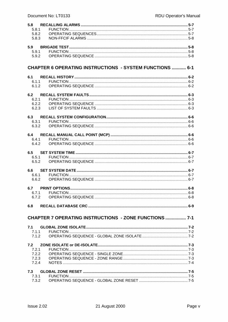
5.8 RECALLING ALARMS ..................................................................................................... 5-75.8.1 FUNCTION ................................................................................................................ 5-75.8.2 OPERATING SEQUENCES...................................................................................... 5-75.8.3 NON-FFCIF ALARMS ............................................................................................... 5-8
5.9 BRIGADE TEST................................................................................................................ 5-85.9.1 FUNCTION ................................................................................................................ 5-85.9.2 OPERATING SEQUENCE ........................................................................................ 5-8
CHAPTER 6 OPERATING INSTRUCTIONS - SYSTEM FUNCTIONS ........... 6-1
6.1 RECALL HISTORY ........................................................................................................... 6-26.1.1 FUNCTION ................................................................................................................ 6-26.1.2 OPERATING SEQUENCE ........................................................................................ 6-2
6.2 RECALL SYSTEM FAULTS............................................................................................. 6-36.2.1 FUNCTION ................................................................................................................ 6-36.2.2 OPERATING SEQUENCE ........................................................................................ 6-36.2.3 LIST OF SYSTEM FAULTS ...................................................................................... 6-3
6.3 RECALL SYSTEM CONFIGURATION............................................................................. 6-66.3.1 FUNCTION ................................................................................................................ 6-66.3.2 OPERATING SEQUENCE ........................................................................................ 6-6
6.4 RECALL MANUAL CALL POINT (MCP) ......................................................................... 6-66.4.1 FUNCTION ................................................................................................................ 6-66.4.2 OPERATING SEQUENCE ........................................................................................ 6-6
6.5 SET SYSTEM TIME .......................................................................................................... 6-76.5.1 FUNCTION ................................................................................................................ 6-76.5.2 OPERATING SEQUENCE ........................................................................................ 6-7
6.6 SET SYSTEM DATE ......................................................................................................... 6-76.6.1 FUNCTION ................................................................................................................ 6-76.6.2 OPERATING SEQUENCE ........................................................................................ 6-7
6.7 PRINT OPTIONS............................................................................................................... 6-86.7.1 FUNCTION ................................................................................................................ 6-86.7.2 OPERATING SEQUENCE ........................................................................................ 6-8
6.8 RECALL DATABASE CRC .............................................................................................. 6-9
CHAPTER 7 OPERATING INSTRUCTIONS - ZONE FUNCTIONS ................ 7-1
7.1 GLOBAL ZONE ISOLATE................................................................................................ 7-27.1.1 FUNCTION ................................................................................................................ 7-27.1.2 OPERATING SEQUENCE - GLOBAL ZONE ISOLATE ........................................... 7-2
7.2 ZONE ISOLATE or DE-ISOLATE..................................................................................... 7-37.2.1 FUNCTION ................................................................................................................ 7-37.2.2 OPERATING SEQUENCE - SINGLE ZONE............................................................. 7-37.2.3 OPERATING SEQUENCE - ZONE RANGE ............................................................. 7-37.2.4 NOTES ...................................................................................................................... 7-4
7.3 GLOBAL ZONE RESET ................................................................................................... 7-57.3.1 FUNCTION ................................................................................................................ 7-57.3.2 OPERATING SEQUENCE - GLOBAL ZONE RESET .............................................. 7-5
RDU Operator's Manual Document No: LT0133
Page vi 21 August 2000 Issue 2.02
7.4 ZONE RESET.................................................................................................................... 7-67.4.1 FUNCTION ................................................................................................................ 7-67.4.2 OPERATING SEQUENCE ........................................................................................ 7-67.4.3 NOTES ...................................................................................................................... 7-7
7.5 ZONE TEST ...................................................................................................................... 7-87.5.1 FUNCTION ................................................................................................................ 7-87.5.2 OPERATING SEQUENCE ........................................................................................ 7-97.5.3 NOTES .................................................................................................................... 7-10
7.6 ZONE STATUS RECALLS ............................................................................................. 7-117.6.1 FUNCTION .............................................................................................................. 7-117.6.2 OPERATING SEQUENCE - ZONE STATUS.......................................................... 7-117.6.3 OPERATING SEQUENCE - ZONE SEARCHES.................................................... 7-12
7.7 ZONE CONFIGURATION RECALL................................................................................ 7-137.7.1 FUNCTION .............................................................................................................. 7-137.7.2 OPERATING SEQUENCE ...................................................................................... 7-13
CHAPTER 8 OPERATING INSTRUCTIONS - RELAY/OUTPUT FUNCTIONS 8-1
8.1 INTRODUCTION............................................................................................................... 8-28.1.1 ANCILLARY RELAYS ............................................................................................... 8-28.1.2 ISOLATION................................................................................................................ 8-2
8.2 ANCILLARY RELAY ISOLATE........................................................................................ 8-38.2.1 ISOLATING/DE-ISOLATING BELLS......................................................................... 8-38.2.2 NON-MAF RDU ANCILLARY ISOLATE/DEISOLATE .............................................. 8-58.2.3 INDIVIDUAL RELAY ISOLATE / DEISOLATE.......................................................... 8-6
8.3 ANCILLARY RELAY RESET SUPERVISION FAULT..................................................... 8-88.3.1 FUNCTION ................................................................................................................ 8-88.3.2 OPERATING SEQUENCE ........................................................................................ 8-8
8.4 ANCILLARY RELAY TEST .............................................................................................. 8-98.4.1 FUNCTION ................................................................................................................ 8-98.4.2 OPERATING SEQUENCE ........................................................................................ 8-9
8.5 BELL TEST ....................................................................................................................... 8-98.5.1 FUNCTION ................................................................................................................ 8-98.5.2 OPERATING SEQUENCE ...................................................................................... 8-10
8.6 ANCILLARY RELAY STATUS RECALL ....................................................................... 8-108.6.1 FUNCTION .............................................................................................................. 8-108.6.2 OPERATING SEQUENCE - RELAY STATUS........................................................ 8-108.6.3 OPERATING SEQUENCE - RELAY SEARCHES .................................................. 8-11
8.7 ANCILLARY RELAY CONFIGURATION RECALL ....................................................... 8-128.7.1 FUNCTION .............................................................................................................. 8-128.7.2 OPERATING SEQUENCE ...................................................................................... 8-12
8.8 NEW ZEALAND MODE TRIAL EVAC OPERATION..................................................... 8-13
CHAPTER 9 OPERATING INSTRUCTIONS - TEST FUNCTIONS ................. 9-1
9.1 SYSTEM TEST.................................................................................................................. 9-29.1.1 FUNCTION ................................................................................................................ 9-29.1.2 OPERATING SEQUENCE ........................................................................................ 9-2
Document No: LT0133 RDU Operator's Manual
Issue 2.02 21 August 2000 Page vii
9.2 LCD/LAMP (LED) TEST ................................................................................................... 9-39.2.1 FUNCTION ................................................................................................................ 9-39.2.2 OPERATING SEQUENCE ........................................................................................ 9-3
9.3 BUZZER TEST.................................................................................................................. 9-39.3.1 FUNCTION ................................................................................................................ 9-39.3.2 OPERATING SEQUENCE ........................................................................................ 9-3
9.4 BATTERY TEST (FP0558 only) ....................................................................................... 9-49.4.1 FUNCTION ................................................................................................................ 9-49.4.2 OPERATING SEQUENCE ........................................................................................ 9-4
9.5 ANCILLARY RELAY/BELLS TEST (FP0558 Only) ........................................................ 9-4
CHAPTER 10 PLACING INTO OPERATION ................................................. 10-1
10.1 GENERAL ............................................................................................................... 10-2
10.2 PLACING INTO OPERATION: FP0558 ................................................................. 10-210.2.1 VISUAL INSPECTION......................................................................................... 10-210.2.2 POWER UP ......................................................................................................... 10-3
10.3 PLACING INTO OPERATION: FP0559 ................................................................. 10-410.3.1 VISUAL INSPECTION......................................................................................... 10-410.3.2 POWER UP ......................................................................................................... 10-4
10.4 COMMISSIONING CHECKLIST: FP0558 .............................................................. 10-5
10.5 COMMISSIONING CHECKLIST: FP0559 .............................................................. 10-7
CHAPTER 11 SYSTEM TESTING AND MAINTENANCE.............................. 11-1
11.1 SYSTEM TESTING AND FAULT FINDING............................................................ 11-2
11.2 SYSTEM MAINTENANCE ...................................................................................... 11-311.2.1 WEEKLY TESTING ............................................................................................. 11-311.2.2 MONTHLY TESTING .......................................................................................... 11-411.2.3 ANNUAL TESTING ............................................................................................. 11-4

RDU Operator's Manual Document No: LT0133
Page viii 21 August 2000 Issue 2.02
THIS PAGE LEFT INTENTIONALLY BLANK

Document No: LT0133 RDU Operator's ManualIntroduction
Issue 2.02 21 August 2000 Page 1-1
CHAPTER 1INTRODUCTION
RDU Operator's Manual Document No: LT0133Introduction
Page 1-2 21 August 2000 Issue 2.02
1.1 SCOPE
The RDU has an Operator Display Panel with an alphanumeric "Liquid Crystal Display"(LCD) and a keypad. The keypad has numeric keys (0 to 9) and specific control keys (e.g.Bells Isolate, Reset, etc).
The operator controls the RDU by pressing the appropriate control keys. The RDU, in turn,prompts the operator by displaying messages on the LCD. Where appropriate, the RDU willprovide the operator with options, numbered from 1 up. The operator selects the desiredoption by pressing the appropriate key on the numeric keypad. Three dots at the end of theLCD indicate that there is more than 1 line of menu options to choose from. Successiveoption lines are displayed by pressing the dot "." ( AND ) key.
Control of the RDU is therefore intuitive to an operator familiar with the basic principles of afire alarm system.
Such an operator may well perform all desired functions without reference to this manual.This manual is intended as a guide to an unfamiliar operator and a reference for the moreexperienced operator.
It is recommended that the building owner's representative who is responsible for the firealarm system, becomes familiar with the RDU operation by practice and by reference to thismanual. The unfamiliar operator should learn the basic principles described in Chapter 2,and become familiar with the RDU system structure and controls.
The RDU is used in both New Zealand and Australia and this manual describes theoperation of both. There are some differences in operation between the two countries andthese are listed in section 2.3.6. The country mode is selected with a programmableparameter.
The Manual is structured in chapters as follows:
Chapter 1: Introduction: An introduction to this manual, other RDU Product manualsand the standards relating to fire alarms.
Chapter 2: System Description; A description of the RDU system features andfunctions.
Chapter 3: Specifications; A summary of RDU system specifications.
Chapter 4: General Display & Keypad Operation; A description of display indications,menu structure and key functions.
Chapter 5: Operating Instructions - Brigade Functions; A detailed description of theoperation and function of keys for FIRE FIGHTER'S USE provided on theRDU ("ACK", "RESET", "ISOLATE", "BRIG TEST" and "NEXT").
Chapter 6: Operating Instructions - System Functions; A description of the operationand function of keys provided on the RDU for system operation. Forexample, Recall History, Recall System Configuration, and Print functions.
Chapter 7: Operating Instructions - Zone Functions; A detailed description of theoperation and function of keys provided on the RDU for zone functions.
Document No: LT0133 RDU Operator's ManualIntroduction
Issue 2.02 21 August 2000 Page 1-3
SCOPE (CONTINUED)
Chapter 8: Operating Instructions - Relay/Output Functions; A description of theRDU relay and output functions.
Chapter 9: Operating Instructions - Test Functions; A description of the operation ofkeys provided on the RDU to initiate tests.eg. System Test, Bells Test, Battery Test etc.
Chapter 10: Placing Into Operation; A description of how to place a system intooperation. Also included is a System Commissioning Checklist.
Chapter 11: System Testing & Maintenance; A description of fault finding, routinetesting and system maintenance.
1.2 ATTACHMENTS
A FIRE FIGHTER'S GUIDE is fixed inside the front cover for quick reference inemergencies.
Your installation company should also provide the following documentation:
(a) An "AS INSTALLED" fire detection system diagram and/or summary, describing theinstalled layout of the FIP and RDU systemconfiguration.
(b) Other "AS INSTALLED" information, such as System configuration parameters.
(c) A Maintenance Log-Book.
1.3 ASSOCIATED DOCUMENTATION
1.3.1 PRODUCT RELATEDThe following manuals for the RDU are available:
RDU Operator's Manual This manual, LT0133, in A4 size.
RDU Installation & Provides information for personnelProgramming Manual responsible for system design, installation and commissioning.
Part number LT0148.
RDU Operator's Manual Document No: LT0133Introduction
Page 1-4 21 August 2000 Issue 2.02
1.3.2 STANDARDS RELATEDThis manual makes reference to the following Australian Standards:
AS1603.4 Automatic Fire Detection and Alarm SystemsPart 4 - Control and Indicating Equipment.
AS1670 Automatic Fire Detection and Alarm Systems-System Design, Installation and Commissioning.
AS1851.8 Maintenance of Fire Protection EquipmentPart 8 - Automatic Fire Detection and Alarm Systems.
AS4050(INT) Fire Detection and fire alarm systems - Fire Fighter's control and indicatingfacilities.
The New Zealand standard referred to is NZS4512 for New Zealand operation.
1.4 GLOSSARY OF ABBREVIATIONS
The following abbreviations and terminology may be used in this manual:
AC Alternating Current"ALM" Display abbreviation for ALARMAS Ancillary SupervisionAVF Alarm Verification, or check alarm.AZC Alarm Zone Circuit, commonly referred to as "Detection Zone"AZF Alarm Zone Facility, commonly referred to as "GROUP"DC Direct CurrentEEPROM Electrically Erasable Programmable Read Only MemoryEOL End Of Line deviceEPROM (U.V.) Erasable PROMF Flashing LED indicatorFFCIF Fire Fighter's Control & Indication Facilities, AS4050 (INT)FIP Fire Indicator Panel"FLT" Display abbreviation for FAULTFRC Flat Ribbon Cable"ISO" Display abbreviation for ISOLATEDLCD Liquid Crystal DisplayLED Light Emitting diode (Visual Indicator)MAF Master Alarm FacilityMCP Manual Call Point (break glass switch)No NumberO/C Open CircuitPCB Printed Circuit BoardPROM Programmable Read-Only MemoryPSU Power Supply UnitRAM Random Access MemoryRDU Remote Display UnitS/C Short CircuitVB Battery Backed VoltageVBF Fused Battery Backed VoltageVNB Non-Battery Backed VoltageVNBF Fused Non-Battery Backed Voltage
Document No: LT0133 RDU Operator's ManualIntroduction
Issue 2.02 21 August 2000 Page 1-5
1.5 GLOSSARY OF TERMINOLOGY
The following terminology is used throughout this manual:
Ancillary Equipment : Equipment external to Fire Alarm systemAncillary Relay : Relay in FIP which operates Ancillary equipmentAuto-Reset : Mode for one person testing of detectorsAuxiliary Output : Output for driving additional LEDs/relaysBaud : Bits per secondBrigade : Fire Brigade Authority, or any other authority which receives
the FIP alarm signalsControl Output : Output from FIP to other equipmentDetector : Alarm Detection Device (electrical transducer)FFCIF Mode : The LCD is displaying the alarms list. Limited key entry
permitted as per AS1603.4Global : A function that may affect more than one zoneMAF Zone : Any zone, Alarm or Ancillary Relay, that is configured to signal
the brigade in the event of an alarm or faultMapping : Programmable causal relationship between inputs and outputsZone : Fire searchable area of buildingDisplay extender board : Used with New Zealand operation only. It has common normal,
fire and defect leds.

RDU Operator's Manual Document No: LT0133Introduction
Page 1-6 21 August 2000 Issue 2.02
THIS PAGE LEFT INTENTIONALLY BLANK
Document No: LT0133 RDU Operator's ManualSystem Description
Issue 2.02 21 August 2000 Page 2-1
CHAPTER 2SYSTEM DESCRIPTION
RDU Operator's Manual Document No: LT0133System Description
Page 2-2 21 August 2000 Issue 2.02
2.1 BASIC PRINCIPLES OF A FIRE ALARM SYSTEM
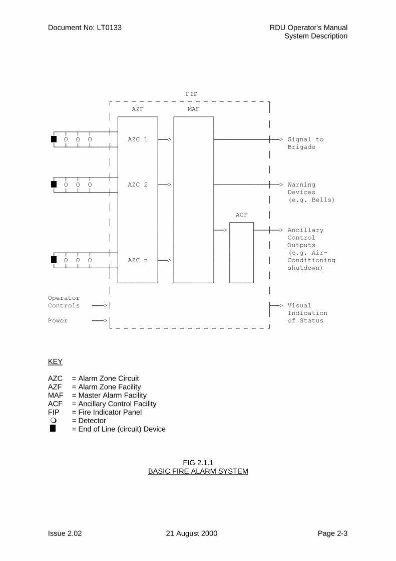
2.1.1 DETECTORS & ALARM ZONE FACILITYA fire alarm system has sensors (electric transducers) which detect the presence of fire.These include heat detectors (thermals), product of combustion detectors (smoke), sprinklersystem water flow switches, manual call points (break glass switches), and others.
The building being protected is divided into areas of limited size called zones. The detectorsin each zone are connected to an electric circuit called an Alarm Zone Circuit (AZC). Theportion of the FIP which controls the AZC is called the Alarm Zone Facility (AZF). When adetector detects fire (i.e. operates) it changes the electrical condition on the AZC and theAZF senses this (zone alarm). The detector remains in the operated state (latches) until theAZF temporarily removes the voltages to it (resets it). N.B. some detectors, e.g. flowswitches, are non-latching.
As well as sensing when a detector has operated the AZF can sense a fault in the AZCwiring (zone fault).
The zone isolate function prevents a zone alarm or fault being registered by the MasterAlarm Facility (MAF). Refer to Fig 2.1.1.
2.1.2 ALARM VERIFICATIONWhen programmed (by the installer) to do so, the AZF may perform a verification function onsensed alarms. This Alarm Verification (AVF) functions as follows:
When an AZF senses that a detector has operated, it does not register alarm immediatelybut delays for a period of time and then resets the detector (typical total delay is 11seconds). If that, or another detector on the AZC operates within the next 150 seconds (orsimilarly programmed period) then the AZF recognises that as a verified alarm, andgenerates alarm to the MAF.
2.1.3 DISPLAYThere is a display of zone status which allows the operator to see if a particular zone isnormal or is in alarm or fault, and if it is isolated.
There is also a separate display of common status which shows if any zone in the system isin alarm, fault, or is isolated.
Document No: LT0133 RDU Operator's ManualSystem Description
Issue 2.02 21 August 2000 Page 2-3
FIP ┌ ─ ─ ─ ─ ─ ─ ─ ─ ─ ─ ─ ─ ─ ─ ─ ─ ─ ─ ─ ┐ AZF MAF │ │ ┌─────────┐ ┌─────────┐ │ │ │ │ │ ┌──┬──┬──┬────┼─┤ │ │ │ O O O │ AZC 1 ├──>│ ├─────────────┼──> Signal to └──┴──┴──┴────┼─┤ │ │ │ Brigade │ │ │ │ │ │ │ │ │ │ │ │ │ │ │ ┌──┬──┬──┬────┼─┤ │ │ │ O O O │ AZC 2 ├──>│ ├─────────────┼──> Warning └──┴──┴──┴────┼─┤ │ │ │ Devices │ │ │ │ │ (e.g. Bells) │ │ │ │ │ │ │ │ │ ACF │ │ │ │ │ │ ┌─────┐ │ │ │ ├──>│ ├───┼──> Ancillary │ │ │ │ │ │ │ Control │ │ │ │ │ │ │ Outputs ┌──┬──┬──┬────┼─┤ │ │ │ │ │ (e.g. Air- O O O │ AZC n ├──>│ │ │ │ │ Conditioning └──┴──┴──┴────┼─┤ │ │ │ │ │ shutdown) │ │ │ │ │ │ │ │ └─────────┘ └─────────┘ └─────┘ │ │OperatorControls ───>│ ├──> Visual │ IndicationPower ───>│ of Status └ ─ ─ ─ ─ ─ ─ ─ ─ ─ ─ ─ ─ ─ ─ ─ ─ ─ ─ ─ ┘
KEY
AZC = Alarm Zone CircuitAZF = Alarm Zone FacilityMAF = Master Alarm FacilityACF = Ancillary Control FacilityFIP = Fire Indicator Panel " = Detector = End of Line (circuit) Device
FIG 2.1.1BASIC FIRE ALARM SYSTEM
RDU Operator's Manual Document No: LT0133System Description
Page 2-4 21 August 2000 Issue 2.02
2.1.4 MASTER ALARM FACILITYThe MAF receives zone status (normal, alarm, fault) and transmits it (via a signalling device)to the Brigade. It also operates the system alerting devices (e.g. electric bells) to warnpeople to evacuate the building.
Individual (or blocks of) zones can be isolated, the Bells output can be isolated, but the MAF(i.e. Brigade signalling) cannot be isolated.
In the RDU it is possible to have alarm zones which are not "mapped" to the MAF and/or theBells, i.e. when in alarm, do not cause a Brigade signal or Bells operation.
2.1.5 ANCILLARY CONTROL FACILITYThe ancillary control facility consists of electric relays (electrically controlled switches) whichcan be used to switch equipment which is not directly part of the Fire Alarm System.Examples include shutting down air conditioning plant, returning lifts to a certain floor andreleasing fire stop doors held open by electric door holders.
2.1.6 REMOTE DISPLAY UNITThe zone status can also be annunciated remotely. The Remote DisplayUnit ( RDU ) performs this function as well as providing the operator with the facility tocontrol the fire alarm system. Zone events can thus be acknowledged, reset or isolated atthe RDU without the operator having to go to the main Fire Indicator Panel ( FIP ). Zonealarm and fault tests can also be initiated at the RDU. A number of RDUs ( 8 max ) canconnect to the same FIP to provide a distributed control and indication facility.
The RDU comes standard with a display to show both individual and common zone status (refer to Section 2.1.3 ). The FP0558 version of the RDU is supplied complete with MasterAlarm (refer Section 2.1.4) and Ancillary Control (refer Section 2.1.5) facilities.
The remainder of this document details the RDU features and operation.
Document No: LT0133 RDU Operator's ManualSystem Description
Issue 2.02 21 August 2000 Page 2-5
2.2 RDU SYSTEM DESCRIPTION
2.2.1 GENERALThe RDU is an intelligent Remote Display Unit (RDU) which performs the functions of a FireFighter's Control and Indicating Facility (FFCIF) as specified by the Australian StandardAS4050 ( int ) for Australian operation and by NZS4512 for New Zealand operation. Thedifferences between New Zealand and Australian operation are listed in section 2.3.6.
It can connect to an F3200, F4000 LCD or F4000 Non-LCD FIP to control the FIP remotelyand to indicate FIP zone status. Up to 8 RDUs can be connected ( multi-drop ) to a FIP toachieve a distributed control and indication system. The functionality of a Non-LCD FIPbased system, in particular, is significantly enhanced by the connection of an RDU becauseof the added ability to display text messages and prompts.
The RDU has a high degree of flexibility. It can be programmed as to which of zones 1 to528 that it will process. This means that in multiple RDU systems each RDU can beassigned the zones corresponding to its own particular sector. Alternatively all RDUs can beconfigured for all zones if required.
An RDU can simply mimic the FIP zone status or it can be programmed to allow the operatorto acknowledge, test, reset or isolate zones from the RDU. Refer to the "RDU Installationand Programming Manual", Section 6.5.4 "Mode" programming.
The RDU is ideally suited to annunciate both relay control and alarm type events. Thefollowing features of the RDU make it ideally suited for these applications:
- Programmable as to which zones are alarm type and which are relay ( shouldbe the same as the FIP ).
- Programmable zone name text, eg. AIR CON. CONTROL CIRCUIT 5, LOWER GROUND FLOOR ALARM
- Individually programmable zone mapping to LCD and LED number, and forFP0558 RDUs, MAF Brigade relays, Bells, and Ancillary 1 & 2 Relays.
- One to one, selective or multiple zone status to LED mapping where 16 ZoneLED display boards are fitted.
- Capability to install 16 Zone Relay Driver type boards instead of 16 Zone LEDDisplay Boards in applications where outputs are to be switched on a perzone basis.
These features allow the RDU to be easily configured to suit a wide range of applications eg.annunciation and control for FIPs configured for automatic fire detection, AS1668 AirConditioning Control, Gas Flood Control etc. Additional mimic-only devices can beconnected to the FIP output to monitor the FIP zone status. For example, floor mimicpanels, or remote outputs for evacuation panels.
Two versions of the RDU are available, FP0558 and FP0559 as shown in Figures 2.1.2 &2.1.3 respectively. FP0558 is supplied in a cabinet(15U, 750H, 550W, 230mmD) complete with a MAF/PSU module and Manual Call Point (MCP ). There is provision for mounting up to four 16 Zone LED boards as an optional extrawithin the cabinet.
RDU Operator's Manual Document No: LT0133System Description
Page 2-6 21 August 2000 Issue 2.02
GENERAL (CONTINUED)
FP0559 is a much smaller, minimally configured RDU. It is a wall mounting, low profile ( 4U,177H, 450W, 50mmD ) unit which is line powered from the FIP. It does not have a MAF/PSUmodule and there is no provision for internal mounting of 16 Zone LED display boards or aManual Call Point ( MCP ). If required these items can connect externally.
2.2.2 DISPLAYSThe primary display of the RDU is a 2 line by 40 character LCD on which the statusmessages and prompts are shown. The LCD has backlight illumination which is turned onwhen there is an alarm or operator interaction. Refer Fig 2.1.3.
Common and various system statuses such as BELLS ISOLATED are displayed on 8 LEDsadjacent to the LCD.
The display panel composed of the LCD, LEDs and operator keypad is called the OperatorDisplay panel. The portion of the display panel within the red border is called the FFCIFdisplay. This meets the requirements of AS4050 (int) for a Fire Fighter's Control andIndicating Facility (FFCIF).
It includes the common status LEDs for ALARM, ISOLATED and FAULT.
As an optional extra, individual zone status (ALARM, ISOLATE and FAULT) can bedisplayed on LEDs by fitting the appropriate number of 16 Zone LED display boards. The 16Zone LED display boards include as standard, an open collector transistor output for eachzone which can be used to drive an internal or remote mimic display.
For New Zealand operation an optional display extender board (PA0742) may be connectedwhich provides 3 common LEDs (alarm,defect,normal), and some inputs (silence alarms,trial evac, building services restore, lamp test, and external defect), and some outputs (the 3common LEDs, an index lamp output and ancillary fire and defect outputs).
2.2.3 SERIAL COMMUNICATIONS PORTA serial port is included in the RDU to provide the 3 ( FP0558 ) or 4 ( FP0559 ) wire linkrequired for connection to the FIP.
Document No: LT0133 RDU Operator's ManualSystem Description
Issue 2.02 21 August 2000 Page 2-7
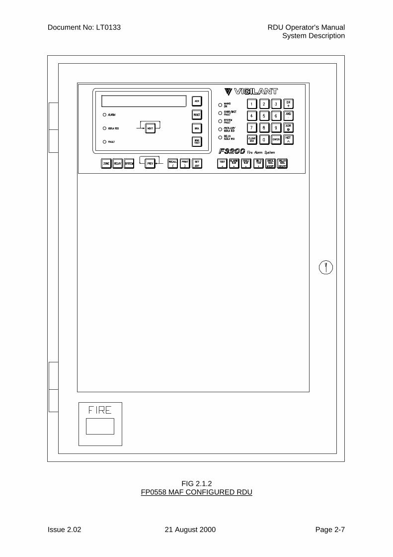
FIG 2.1.2FP0558 MAF CONFIGURED RDU
RDU Operator's Manual Document No: LT0133System Description
Page 2-8 21 August 2000 Issue 2.02
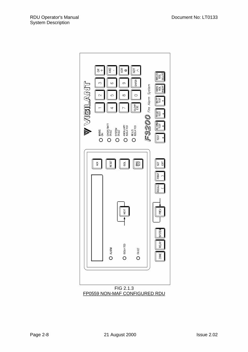
FIG 2.1.3FP0559 NON-MAF CONFIGURED RDU
Document No: LT0133 RDU Operator's ManualSystem Description
Issue 2.02 21 August 2000 Page 2-9
2.2.4 LOGGING PRINTERA serial printer may be connected to the RDU printer/programmer port to provide a log ofevents and operator actions, and also to print the programmed database.
Events which are printed include:Zone Events, e.g. Alarm, Fault;Zone Commands, e.g. Reset, Isolate, Alarm test, Fault test;System Events, e.g. communication failures, battery faults, etc.
The printout includes the time and date, the cause of the event (e.g. Zone, Relay, or RDU),and the event type. Events and commands for zones that have had a text nameprogrammed also have the name printed. The RDU is able to store up to 70 events forprinting, being the first 70 events to occur.
As events are printed, more events are able to be put into the list. If events cannot be putinto the list because it is full, the RDU keeps a count of those events it has had to discard.When the RDU is next able to put more events into the list, it prints out the number of eventsit had to discard. The RDU separately maintains an internal history of the 70 most recentevents. This history can be viewed on the LCD.
2.2.5 PROGRAMMER PORTThe printer/programmer port can be used to save or load the programmed database. Thesaved database can then be reloaded into the RDU ( or another RDU ) at some future timeand this is much faster than reprogramming the entire database from the RDU keypad.
Please refer to Section 6.3.4 of the RDU "Installation & Programming Manual" for a moredetailed description.
2.2.6 FP0558: MAF-CONFIGURED RDU ONLY 2.2.6.1 MAF OutputsThe FP0558 provides 7 relays as standard on the MAF/PSU module. These can be used toswitch alarm bells and ancillary equipment such as door holders, air-conditioning shutdown,etc. The MAF standby, alarm, fault and isolate relays should not be used for signalling to thebrigade, the brigade connection should be made to the FIP.
Each zone can be programmed to operate these relays when the appropriate condition ispresent, eg Alarm, Fault, Isolate etc.
2.2.6.2 Power SupplyThe FP0558 RDU has a 3 Amp battery charger/power supply as standard. There isadequate room for large batteries. An optional 6 Amp battery charger/power supply isavailable.
Fuse protected battery backed and non-battery backed supplies are available to powerexternal loads such as bells, illuminated signs, interposing relays, gas release solenoids,door holders, etc.
RDU Operator's Manual Document No: LT0133System Description
Page 2-10 21 August 2000 Issue 2.02
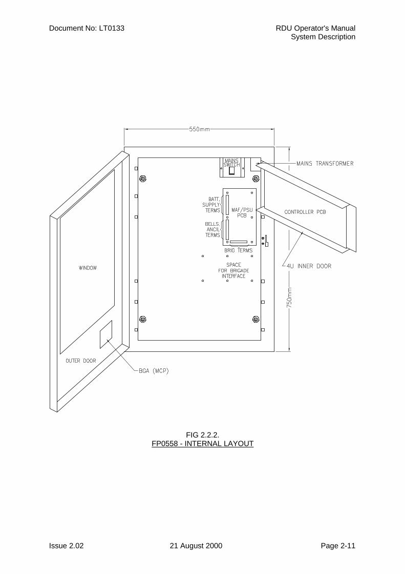
2.3 SYSTEM STRUCTURE & CONFIGURATION
2.3.1 PCB MODULES: FP0558The printed circuit boards which could be used in the FP0558 RDU are as follows:
Controller/DisplayThis mounts on 4U inner door. It controls all other PCBs and the keypad, LCD, buzzer andstatus LEDs.
MAF/PSUThis mounts on the cabinet rear wall. It includes the battery charger, power supply, fuses,brigade plus ancillary relays and screw terminal connectors for input of communications fromthe FIP.
16 LED Display (optional)This mounts on the optional 7U inner door. Includes 16 sets of 3 LEDs plus 16 opencollector outputs driven off the zone alarm status.
16 Relay Driver ( optional )Mounts on 7U inner door. It includes 16 open collector outputs driven off the zone alarmstatus.
16 Relay Board ( optional )Mounts internally in cabinet. Includes 16 sets of voltage free change-over contacts driven bythe open collector outputs of either the 16 Zone LED Display boards or the 16 Relay Driverboards.
Display Extender Board (optional)This is used in New Zealand mode only and may mount on the optional 7U inner door or inan external picture frame cabinet.
2.3.2 STRUCTURE & INTER-CONNECTION : FP0558A basic MAF Configured RDU system has one Controller/Display and one MAF/PSU,interconnected by Flat Ribbon Cable (FRC). Refer to Fig 2.2.2.
Where 16 Zone Display boards are fitted, the default configuration is that:Zone 1 corresponds to the top row of LEDs (3) on the left most Display, Zone 2 to the rowbelow it, etc, (top to bottom, left to right). Mapping zones and relays to LEDs in otherpatterns is programmable.
Display boards may also annunciate Relay status. Alarm LED on <-> relay energised,Isolated LED on <-> relay isolated, Fault LED on <-> relay wiring fault (i.e. supervision fault).
Document No: LT0133 RDU Operator's ManualSystem Description
Issue 2.02 21 August 2000 Page 2-11
FIG 2.2.2.FP0558 - INTERNAL LAYOUT
RDU Operator's Manual Document No: LT0133System Description
Page 2-12 21 August 2000 Issue 2.02
2.3.3 PCB MODULES: FP0559The printed circuit boards which are used in a Non-MAF configured RDU are as follows:
- Controller/Display as described in Section 2.3.1.
- Remote Termination Board for input of power and communications from the host.
- Optional external connection of 16 Zone LED Display/Relay Driver Boards (plusRelay Board) as required providing a suitable cabinet and PSU can be arranged.
- Display extender board (optional)This is used in New Zealand mode only.
2.3.4 STRUCTURE & INTER-CONNECTION : FP0559A basic Non-MAF Configured RDU system has one Controller/Display and one remotetermination board interconnected by Flat Ribbon Cable (FRC).
16 Zone Display/Relay driver boards can be driven off the "LED OUT" connector on theController/Display board. An extender cabinet could be used to mount the boards, anexternal PSU would also be required. The mapping of zones to LEDs is as described inSection 2.3.2.
2.3.5 CONFIGURATIONAn RDU is configured by the system designer and installation staff to suit a particularcustomer's requirements. This is done by:
Fitting and connecting the required modules (eg. MAF/PSU module, 16 Zone display/relay driver boards if any );
adjusting or removing links on the PCBs;programming the RDU through the keypad.
The manual call points (MCPs), warning devices, ancillary equipment and field wiring thatare connected to the RDU must match the programmed configuration. The RDU zone type (relay/alarm, default = alarm ) must be programmed to match the FIP zone type. Note thatrelay type zones will not generate FFCIF alarm type events at the RDU. Where 16 Zone LEDdisplay/relay driver boards are fitted the board type must also be programmed ( default =display );
It is not expected that the operator should program the RDU.The Operator should not alter the links or system configuration.
** PLEASE NOTE **
If your building or occupancy requirements change, then the RDU or FIP may requirereprogramming, so please consult your installation or maintenance company.
Document No: LT0133 RDU Operator's ManualSystem Description
Issue 2.02 21 August 2000 Page 2-13
2.3.6 NEW ZEALAND MODE OPERATIONThe RDU may operate in either Australian or New Zealand mode as selected by aprogrammable parameter. The differences for New Zealand mode operation are listed here.
1. Display extender board.
This is an optional board (PA0742) which may be used in NZ mode and providessome outputs and inputs as follows.Outputs - common normal, alarm and defect LEDs
- index lamp output- ancillary fire and defect outputs
Inputs - silence alarms- trial evac- building services restore- lamp test- external defect
2. FIP battery very low alarm event.
When the FIP powers up it will immediately generate a battery very low alarm andsignal brigade alarm until reset. It will also send an event to the RDU forannunciation. This event can be acknowledged and reset at the RDU (or FIP)providing acknowledgement and reset are enabled at the RDU. A battery very lowstatus can also occur at the RDU. This will be logged to the history and a defectcondition generated, but there is no FFCIF event or brigade alarm signalled for this.
3. MAF board usage.
The MAF board used for New Zealand operation is the same as used for Australianoperation. In NZ mode, the brigade alarm relay is normally energised and de-energises for alarm - the opposite of Australian mode. The "MCP" (manual call point)input on the MAF board cannot be used when in New Zealand mode and is ignored.
4. Bells isolate and Silence Alarms operation.
The Silence Alarms input on the display extender board is normally connected to akeyswitch which can be used to silence the bells i.e. de-energise the bells relay ateither or both the RDU and the FIP. This is dependent on programming. Refer tothe RDU Installation and Programming Manual (LT0148).
5. Trial evacuation input.
The trial evac keyswitch connected to the display extender board can be used toenergise the bells relay at the FIP or RDU if programmed to. Refer to the RDUInstallation and Programming Manual (LT0148). Trial evac overrides bells isolateand the Silence Alarms keyswitch and operates the bells even if the bells areisolated.
6. Building services restore input.
The BSR keyswitch connected to the display extender board is used to isolateancillary outputs at the FIP and/or RDU depending on programming. Refer to theRDU Installation and Programming Manual (LT0148).
RDU Operator's Manual Document No: LT0133System Description
Page 2-14 21 August 2000 Issue 2.02
NEW ZEALAND MODE OPERATION (CONTINUED)
7. Battery low monitoring.
The battery low input is monitored continuously (Australian mode only monitors thebattery low input during a battery test). A daily automatic 40 minute battery test isdone as part of the daily "Auto Test" initiated by the FIP. A one minute battery testcan be initiated from the RDU front panel keypad. A battery test can only be done ifthe RDU has a MAF board connected. Battery test resistors which are normallypresent on the MAF board for Australian operation are removed for New Zealandoperation.
Document No: LT0133 RDU Operator's ManualSystem Specifications
Issue 2.02 21 August 2000 Page 3-1
CHAPTER 3SYSTEM SPECIFICATIONS
RDU Operator's Manual Document No: LT0133System Specifications
Page 3-2 21 August 2000 Issue 2.02
3.1 GENERAL
3.1.1 PART NUMBERSFP0558, FP, REMOTE DISPLAY UNIT (RDU), FULL CABINET & MAF/PSUFull size cabinet complete with MCP mounted externally, Controller/Display with FFCIF LCD& Keypad, MAF/PSU (includes 7 relays, 3A PSU), Blanking plate covering lower 7U of 15Uheight cabinet.
FP0559, FP, REMOTE DISPLAY UNIT (RDU), SLIMLINE, WALL MOUNTWall mount, low profile cabinet with Controller/Display with FFCIF LCD & Keypad.
FP0577, FP, REMOTE DISPLAY UNIT (RDU), 4U 19” RAC4U, 19” rack mounting RDU Controller for mounting in a 19” rack cabinet.
FP0585, FP, REMOTE DISPLAY UNIT (RDU), SMALL CABINET, C/W MAF/PSU8U, 19” cabinet containing RDU Controller and MAF/PSU. No space for LED mounting.
FP0772, FP, REMOTE DISPLAY UNIT (RDU), SLIMLINE, FLUSH MOUNTFlush mounting cabinet containing RDU Controller, no MAF/PSU.
3.1.2 CONTROLSKEYPAD
Type : Polyester MembraneKeypress : Buzzer gives short "beep" for valid keypressNumber ofKeys : 34 (plus 5 concealed with no function)FFCIF Keys : ACK; RESET; ISOL; BRIG TEST; NEXT4x4 Keypad : Digits 0-9; Clear/Esc; Enter; 4 x Logic Keys
KEYPAD FUNCTIONS
Zone Functions - Acknowledge, Reset, Isolate, Recall, Alarm test, Fault test
Relay Functions - Acknowledge, Reset, Isolate, Recall
Ancillary Functions - Test, Isolate, Reset, Recall (requires MAF/PSU)
System Functions - Buzzer Test, Display Test- System Test- Recall : Alarms, Faults, Isolates, System Faults, History,
Database CRC- Set time and date- Program and view parameters- Print, save and verify database- Battery Test, Bell Test, Bell Isolate
Brigade Functions - Acknowledge Alarms- View alarms (Next & Prev)- Reset acknowledged zones in alarm- Isolate acknowledged zones in alarm- Brigade Test ( Non-Mimic modes only )
Document No: LT0133 RDU Operator's ManualSystem Specifications
Issue 2.02 21 August 2000 Page 3-3
BUZZER (INTERNAL SOUNDER)
Mounted on Controller/Display PCB
Tone Steady : FaultUnisolated zone faultUnisolated ancillary relay supervision faultSystem Fault
Pulsing 2Hz : Alarm (note 1)
Slow Pulse : Door closed ( FP0558 ) or keyswitch not operated ( FP0559 ) withDatabase Write Enabled (Lk7) or RDU left in program mode. For NewZealand operation - door closed or keyswitch not operated when anoff normal condition exists (see definition of common normal led for listof off normal conditions.)
Cadence : System-Test failed (note 2)
Short Pulse : Valid keypress
Long Pulse : Invalid keypress
Notes
1. Relay type and Non-LCD configured zones will not turn on the alarm buzzer. This isbecause FFCIF LCD alarm type events are not generated for zones configured in thisway.
2. The System Test failure cadence is fast pulses with a pause.
3.1.3 DISPLAYSStandard Operator Display
Includes : LCD; FFCIF LEDs; System Status LEDsPanel Size : 19", 4UFFCIF Type : 3 (common indicators & common controls)Standard : Complies with AS4050 (int) - 1992LCD Size : 2 Lines of 40 characters - 5.5mm (H) x 3.2mm (W) per characterSite Name : 40 Characters max.Zone Name : 30 Characters max.Relay Name : 30 Characters max.FFCIF LEDs : ALARM (red); ISOLATED (yellow); FAULT (yellow)SystemStatus LEDs : MAINS ON (green); CHGR/BATT FAULT (yellow); SYSTEM FAULT
(yellow); ANCILLARY ISOLATED (yellow); BELLS ISOLATED (yellow)Internal LEDs : Mains On (green), Fuse Blown (yellow) on MAF/PSU pcb.
RDU Operator's Manual Document No: LT0133System Specifications
Page 3-4 21 August 2000 Issue 2.02
DISPLAYS (CONTINUED)
Optional Additional LED Displays
Requires 1 x ME0060 plus 1 x FZ3031 plus 1-3 x FP0475 as required.
ME0060, MECH ASSY, 1901-79, RAC EXT INNER DOOR(19", 7U, mounts up to 4 x 16 Zone LED Display Bds)
FZ3031,KIT,F3200,16 ZONE LED DISPLAY,LHS POSITION(as per FP0475, but with 1.2m FRC, allows mtg of Display Bd in furthest left position.Required for first display).
FP0475, FP, 16 ZONE DISPLAY EXTENDER KIT, 1901-26
Includes : 1 x LED Display Bd (16 zone parallel LED display); FRC; Power leads;zone name label.
Format : 7U Parallel LED display mounts directly below the standard 4U LCD.The LCD and common LEDs operate as per standard. Zone status isshown on the zone LEDs.
Zone LEDs : ALARM (red); FAULT (yellow); ISOLATED (yellow)
Name Space : 10mm x 60mm per zone on paper label.E.g. 2 lines of 23 characters at 10 per inch.
Optional NZ Display Extender Board
This is used in New Zealand mode only and has a common normal LED (green), commonalarm LED (red), and common defect LED (yellow).
3.1.4 ENVIRONMENTAL
Operating Temperature : -5°C to 45°C (Ambient)Relative Humidity : 95% maximum @ 40°C (non-condensing)
Document No: LT0133 RDU Operator's ManualSystem Specifications
Issue 2.02 21 August 2000 Page 3-5
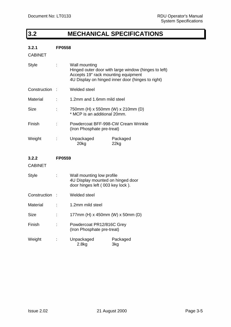
3.2 MECHANICAL SPECIFICATIONS
3.2.1 FP0558CABINET
Style : Wall mountingHinged outer door with large window (hinges to left)Accepts 19" rack mounting equipment4U Display on hinged inner door (hinges to right)
Construction : Welded steel
Material : 1.2mm and 1.6mm mild steel
Size : 750mm (H) x 550mm (W) x 210mm (D)* MCP is an additional 20mm.
Finish : Powdercoat BFF-998-CW Cream Wrinkle(Iron Phosphate pre-treat)
Weight : Unpackaged Packaged20kg 22kg
3.2.2 FP0559CABINET
Style : Wall mounting low profile4U Display mounted on hinged doordoor hinges left ( 003 key lock ).
Construction : Welded steel
Material : 1.2mm mild steel
Size : 177mm (H) x 450mm (W) x 50mm (D)
Finish : Powdercoat PR12/816C Grey(Iron Phosphate pre-treat)
Weight : Unpackaged Packaged2.8kg 3kg
RDU Operator's Manual Document No: LT0133System Specifications
Page 3-6 21 August 2000 Issue 2.02
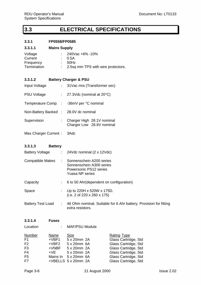
3.3 ELECTRICAL SPECIFICATIONS
3.3.1 FP0558/FP05853.3.1.1 Mains SupplyVoltage : 240Vac +6% -10%Current : 0.5AFrequency : 50HzTermination : 2.5sq mm TPS with wire protectors.
3.3.1.2 Battery Charger & PSUInput Voltage : 31Vac rms (Transformer sec)
PSU Voltage : 27.3Vdc (nominal at 20°C)
Temperature Comp. : -36mV per °C nominal
Non-Battery Backed : 28.0V dc nominal
Supervision : Charger High 28.1V nominalCharger Low 26.6V nominal
Max Charger Current : 3Adc
3.3.1.3 BatteryBattery Voltage : 24Vdc nominal (2 x 12Vdc)
Compatible Makes : Sonnenschein A200 seriesSonnenschein A300 seriesPowersonic PS12 seriesYuasa NP series
Capacity : 6 to 50 Ahr(dependent on configuration)
Space : Up to 220H x 520W x 175D.(i.e. 2 of 220 x 260 x 175)
Battery Test Load : 46 Ohm nominal. Suitable for 6 Ahr battery. Provision for fittingextra resistors.
3.3.1.4 FusesLocation : MAF/PSU Module
Number Name Size Rating TypeF1 +VBF1 5 x 20mm 2A Glass Cartridge, StdF2 +VBF2 5 x 20mm 6A Glass Cartridge, StdF3 +VNBF 5 x 20mm 2A Glass Cartridge, StdF4 +VE 5 x 20mm 2A Glass Cartridge, StdF5 Mains In 5 x 20mm 6A Glass Cartridge, StdF7 +VBELLS 5 x 20mm 2A Glass Cartridge, Std
Document No: LT0133 RDU Operator's ManualSystem Specifications
Issue 2.02 21 August 2000 Page 3-7
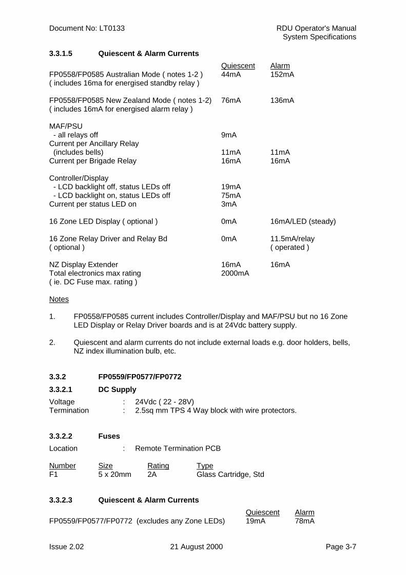
3.3.1.5 Quiescent & Alarm CurrentsQuiescent Alarm
FP0558/FP0585 Australian Mode ( notes 1-2 ) 44mA 152mA( includes 16ma for energised standby relay )
FP0558/FP0585 New Zealand Mode ( notes 1-2) 76mA 136mA( includes 16mA for energised alarm relay )
MAF/PSU - all relays off 9mACurrent per Ancillary Relay (includes bells) 11mA 11mACurrent per Brigade Relay 16mA 16mA
Controller/Display - LCD backlight off, status LEDs off 19mA - LCD backlight on, status LEDs off 75mACurrent per status LED on 3mA
16 Zone LED Display ( optional ) 0mA 16mA/LED (steady)
16 Zone Relay Driver and Relay Bd 0mA 11.5mA/relay( optional ) ( operated )
NZ Display Extender 16mA 16mATotal electronics max rating 2000mA( ie. DC Fuse max. rating )
Notes
1. FP0558/FP0585 current includes Controller/Display and MAF/PSU but no 16 ZoneLED Display or Relay Driver boards and is at 24Vdc battery supply.
2. Quiescent and alarm currents do not include external loads e.g. door holders, bells,NZ index illumination bulb, etc.
3.3.2 FP0559/FP0577/FP07723.3.2.1 DC SupplyVoltage : 24Vdc ( 22 - 28V)Termination : 2.5sq mm TPS 4 Way block with wire protectors.
3.3.2.2 FusesLocation : Remote Termination PCB
Number Size Rating TypeF1 5 x 20mm 2A Glass Cartridge, Std
3.3.2.3 Quiescent & Alarm CurrentsQuiescent Alarm
FP0559/FP0577/FP0772 (excludes any Zone LEDs) 19mA 78mA
RDU Operator's Manual Document No: LT0133System Specifications
Page 3-8 21 August 2000 Issue 2.02
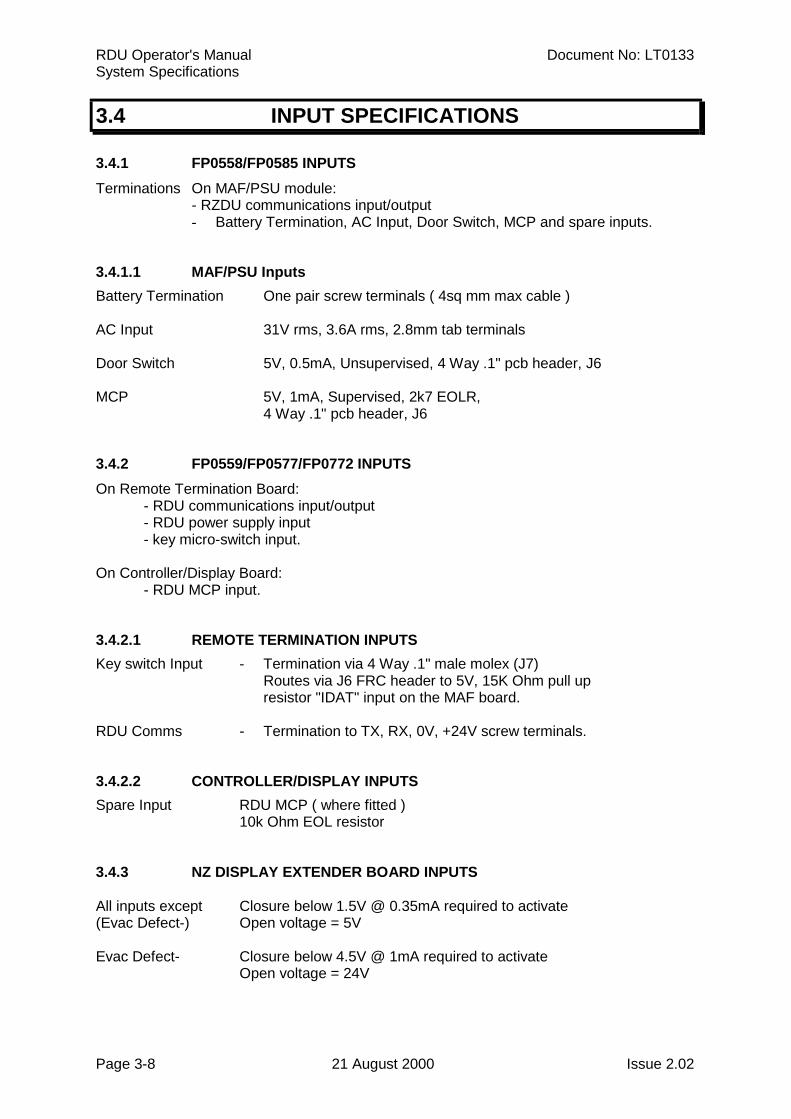
3.4 INPUT SPECIFICATIONS
3.4.1 FP0558/FP0585 INPUTSTerminations On MAF/PSU module: - RZDU communications input/output
- Battery Termination, AC Input, Door Switch, MCP and spare inputs.
3.4.1.1 MAF/PSU InputsBattery Termination One pair screw terminals ( 4sq mm max cable )
AC Input 31V rms, 3.6A rms, 2.8mm tab terminals
Door Switch 5V, 0.5mA, Unsupervised, 4 Way .1" pcb header, J6
MCP 5V, 1mA, Supervised, 2k7 EOLR,4 Way .1" pcb header, J6
3.4.2 FP0559/FP0577/FP0772 INPUTSOn Remote Termination Board:
- RDU communications input/output- RDU power supply input- key micro-switch input.
On Controller/Display Board:- RDU MCP input.
3.4.2.1 REMOTE TERMINATION INPUTSKey switch Input - Termination via 4 Way .1" male molex (J7) Routes via J6 FRC header to 5V, 15K Ohm pull up
resistor "IDAT" input on the MAF board.
RDU Comms - Termination to TX, RX, 0V, +24V screw terminals.
3.4.2.2 CONTROLLER/DISPLAY INPUTSSpare Input RDU MCP ( where fitted )
10k Ohm EOL resistor
3.4.3 NZ DISPLAY EXTENDER BOARD INPUTS
All inputs except Closure below 1.5V @ 0.35mA required to activate(Evac Defect-) Open voltage = 5V
Evac Defect- Closure below 4.5V @ 1mA required to activateOpen voltage = 24V
Document No: LT0133 RDU Operator's ManualSystem Specifications
Issue 2.02 21 August 2000 Page 3-9
3.5 OUTPUT SPECIFICATIONS
3.5.1 CONTROLLER PRINTER/PROGRAMMERPrinter/Programmer Port
Form Pseudo RS232Rx, Tx, 0V signals only
Transient Protection Allows external wiringTransmission Rate 9600 Baud ( programmable ) ASCII Xon, Xoff ProtocolTermination 4 Way .156" male molex (J1)
3.5.2 16 LED DISPLAY / RELAY DRIVER BDThe most common use the open collector outputs will be to switch LEDs on "mimic" displays.The mimic outputs can also be used to drive the 16 way Relay Bd PA0470.
Output Type : 16 * Open Collector driven by alarm statusOutput Rating : 200mA ( max ) current sink capability @ 30V
3.5.3 MAF/PSU OUTPUTSMAF/PSU OUTPUTS
Brigade Relays
Number/Type 4 relays, 1 pole changeover contacts
Standby Normally energisedDe-energises on battery fail or panel fail or in program mode.
Fault, Isolated, Normally de-energisedAlarm (Australian) Energise on active state
Alarm (New Zealand) Normally energised. De-energise for alarm.
Rating ELV only30V, 5Adc resistive30V, 3Adc inductive
Isolation 1500V rms contact to coil.
Ancillary & Bells
Number 3 relays
RDU Operator's Manual Document No: LT0133System Specifications
Page 3-10 21 August 2000 Issue 2.02
MAF/PSU OUTPUTS (CONTINUED)
Anc 1, Anc 2 1 Pole changeover contactsVoltage-free
Rating ELV only30V, 2Adc resistive30V, 1Adc inductive
Operation Programmable
Default Active on any unisolated Zone Alarm.
Supervision Separate terminal, 2 modes, programmable(refer to Installation & Programming manual)
Anc 3/Bells 1 relay, 2 poleLink selectable function
Standard Format Bells, Switched 24Vdc output2 terminals, Bells +, -
Rating 24V, 1.5A Inductive Bells
Supervision Programmable, requires diode at each deviceNumber of Branches Resistor End of Line
(each branch)1 3k32 6k83 10k
RZDU Comms
Tx, Rx, 0V 3 Wire (+VBF2 also available)
Transmission Rate 1200 Baud
Protocol Vigilant RZDU
3.5.4 REMOTE TERMINATION BOARD OUTPUT SPECSREMOTE TERMINATION BOARD OUTPUTS
RZDU Comms & Power
Tx, Rx, 0V, +24V 3 Wire Tx, Rx, & 0v comms connection to J2 plus +24V inputconnection to J1 for power ( ie. 4 wire connection to FIP ).
Transmission Rate 1200 Baud
Protocol Vigilant RZDU
Document No: LT0133 RDU Operator's ManualSystem Specifications
Issue 2.02 21 August 2000 Page 3-11
3.5.5 NZ DISPLAY EXTENDER BOARD OUTPUTSOpen Collector pulling down to 0V
All outputs except Off Voltage = 30V maxLamp +, Lamp - On Voltage = 1.1V @ 100mA (max)
Lamp + (Open Collector) Off Voltage = 0VPull up to VBATT On Voltage = VBATT -1V @ 400mA (max)
Lamp - Connected to Batt -

RDU Operator's Manual Document No: LT0133System Specifications
Page 3-12 21 August 2000 Issue 2.02
THIS PAGE LEFT INTENTIONALLY BLANK
Document No: LT0133 RDU Operator's ManualGeneral Display & Keyboard Operation
Issue 2.02 21 August 2000 Page 4-1
CHAPTER 4GENERAL DISPLAY & KEYPAD OPERATION
RDU Operator's Manual Document No: LT0133General Display & Keyboard Operation
Page 4-2 21 August 2000 Issue 2.02
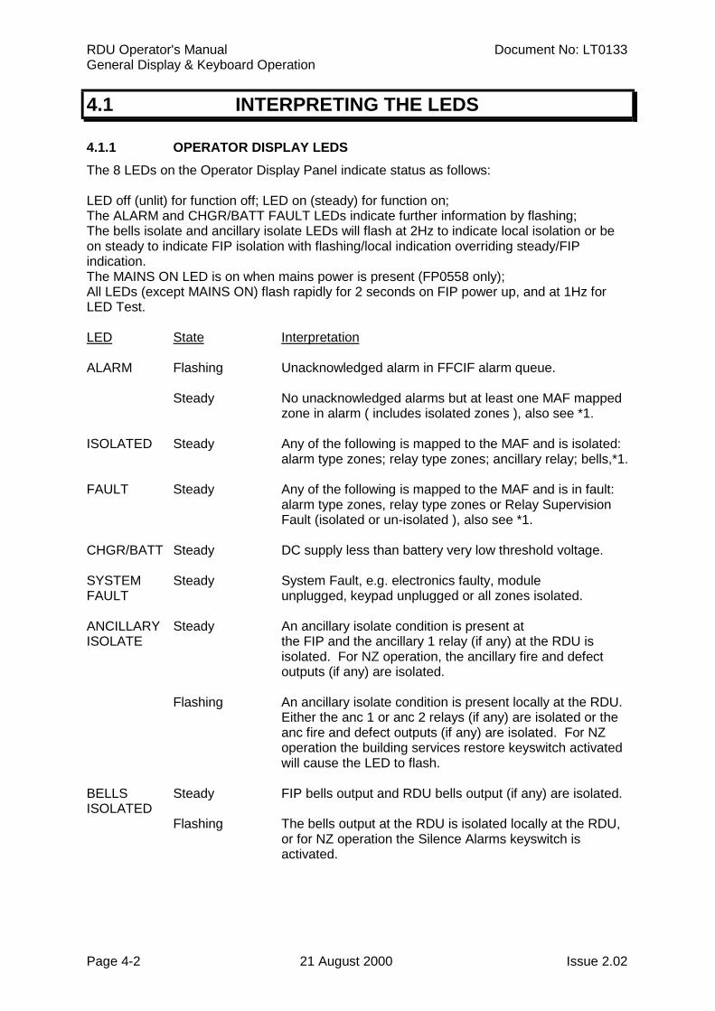
4.1 INTERPRETING THE LEDS
4.1.1 OPERATOR DISPLAY LEDSThe 8 LEDs on the Operator Display Panel indicate status as follows:
LED off (unlit) for function off; LED on (steady) for function on;The ALARM and CHGR/BATT FAULT LEDs indicate further information by flashing;The bells isolate and ancillary isolate LEDs will flash at 2Hz to indicate local isolation or beon steady to indicate FIP isolation with flashing/local indication overriding steady/FIPindication.The MAINS ON LED is on when mains power is present (FP0558 only);All LEDs (except MAINS ON) flash rapidly for 2 seconds on FIP power up, and at 1Hz forLED Test.
LED State Interpretation
ALARM Flashing Unacknowledged alarm in FFCIF alarm queue.
Steady No unacknowledged alarms but at least one MAF mappedzone in alarm ( includes isolated zones ), also see *1.
ISOLATED Steady Any of the following is mapped to the MAF and is isolated:alarm type zones; relay type zones; ancillary relay; bells,*1.
FAULT Steady Any of the following is mapped to the MAF and is in fault:alarm type zones, relay type zones or Relay SupervisionFault (isolated or un-isolated ), also see *1.
CHGR/BATT Steady DC supply less than battery very low threshold voltage.
SYSTEM Steady System Fault, e.g. electronics faulty, moduleFAULT unplugged, keypad unplugged or all zones isolated.
ANCILLARY Steady An ancillary isolate condition is present atISOLATE the FIP and the ancillary 1 relay (if any) at the RDU is
isolated. For NZ operation, the ancillary fire and defectoutputs (if any) are isolated.
Flashing An ancillary isolate condition is present locally at the RDU.Either the anc 1 or anc 2 relays (if any) are isolated or theanc fire and defect outputs (if any) are isolated. For NZoperation the building services restore keyswitch activatedwill cause the LED to flash.
BELLS Steady FIP bells output and RDU bells output (if any) are isolated.ISOLATED
Flashing The bells output at the RDU is isolated locally at the RDU,or for NZ operation the Silence Alarms keyswitch isactivated.
Document No: LT0133 RDU Operator's ManualGeneral Display & Keyboard Operation
Issue 2.02 21 August 2000 Page 4-3
OPERATOR DISPLAY LEDS (CONTINUED)
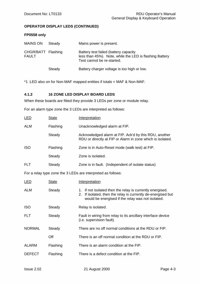
FP0558 only
MAINS ON Steady Mains power is present.
CHGR/BATT Flashing Battery test failed (battery capacityFAULT less than 45%). Note, while the LED is flashing Battery
Test cannot be re-started.
Steady Battery charger voltage is too high or low.
*1 :LED also on for Non-MAF mapped entities if totals = MAF & Non-MAF.
4.1.2 16 ZONE LED DISPLAY BOARD LEDSWhen these boards are fitted they provide 3 LEDs per zone or module relay.
For an alarm type zone the 3 LEDs are interpreted as follows:
LED State Interpretation
ALM Flashing Unacknowledged alarm at FIP.
Steady Acknowledged alarm at FIP. Ack'd by this RDU, anotherRDU or directly at FIP or Alarm in zone which is isolated.
ISO Flashing Zone is in Auto-Reset mode (walk test) at FIP.
Steady Zone is isolated.
FLT Steady Zone is in fault. (Independent of isolate status)
For a relay type zone the 3 LEDs are interpreted as follows:
LED State Interpretation
ALM Steady 1. If not isolated then the relay is currently energised.2. If isolated, then the relay is currently de-energised but
would be energised if the relay was not isolated.
ISO Steady Relay is isolated.
FLT Steady Fault in wiring from relay to its ancillary interface device(i.e. supervision fault).
NORMAL Steady There are no off normal conditions at the RDU or FIP.
Off There is an off normal condition at the RDU or FIP.
ALARM Flashing There is an alarm condition at the FIP.
DEFECT Flashing There is a defect condition at the FIP.
RDU Operator's Manual Document No: LT0133General Display & Keyboard Operation
Page 4-4 21 August 2000 Issue 2.02
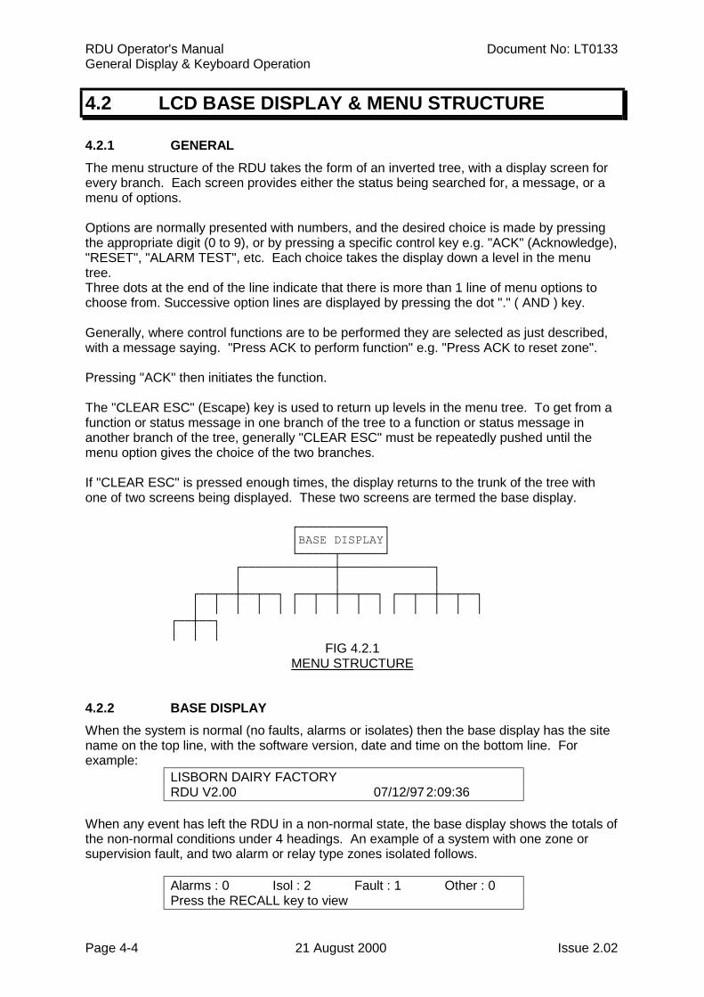
4.2 LCD BASE DISPLAY & MENU STRUCTURE
4.2.1 GENERALThe menu structure of the RDU takes the form of an inverted tree, with a display screen forevery branch. Each screen provides either the status being searched for, a message, or amenu of options.
Options are normally presented with numbers, and the desired choice is made by pressingthe appropriate digit (0 to 9), or by pressing a specific control key e.g. "ACK" (Acknowledge),"RESET", "ALARM TEST", etc. Each choice takes the display down a level in the menutree.Three dots at the end of the line indicate that there is more than 1 line of menu options tochoose from. Successive option lines are displayed by pressing the dot "." ( AND ) key.
Generally, where control functions are to be performed they are selected as just described,with a message saying. "Press ACK to perform function" e.g. "Press ACK to reset zone".
Pressing "ACK" then initiates the function.
The "CLEAR ESC" (Escape) key is used to return up levels in the menu tree. To get from afunction or status message in one branch of the tree to a function or status message inanother branch of the tree, generally "CLEAR ESC" must be repeatedly pushed until themenu option gives the choice of the two branches.
If "CLEAR ESC" is pressed enough times, the display returns to the trunk of the tree withone of two screens being displayed. These two screens are termed the base display.
┌────────────┐ │BASE DISPLAY│ └─────┬──────┘ ┌─────────────┼─────────────┐ │ │ │ ┌──┬──┼──┬──┐ ┌──┬──┼──┬──┐ ┌──┬──┼──┬──┐ │ │ │ │ │ │ │ │ │ │ │ │ │ │ │ ┌──┼──┐ │ │ │
FIG 4.2.1MENU STRUCTURE
4.2.2 BASE DISPLAYWhen the system is normal (no faults, alarms or isolates) then the base display has the sitename on the top line, with the software version, date and time on the bottom line. Forexample:
LISBORN DAIRY FACTORYRDU V2.00 07/12/97 2:09:36
When any event has left the RDU in a non-normal state, the base display shows the totals ofthe non-normal conditions under 4 headings. An example of a system with one zone orsupervision fault, and two alarm or relay type zones isolated follows.
Alarms : 0 Isol : 2 Fault : 1 Other : 0Press the RECALL key to view
Document No: LT0133 RDU Operator's ManualGeneral Display & Keyboard Operation
Issue 2.02 21 August 2000 Page 4-5
BASE DISPLAY (CONTINUED)
The non-normal conditions can be viewed by pressing the "RECALL" key followed by thedesired option ( refer to Chapter 6 ). Once the condition is displayed, control functions suchas ISOL (Isolate) and RESET can be performed.
The totals are as follows:
Alarms Includes alarms on maf-mapped alarm type zones ( including isolated andNon-LCD zones ), also see *1.
Isol Includes all isolated maf-mapped alarm & relay type zones, and ( FP0558only ) ancillary plus bell relays. Also see *1.
Faults Includes all faults on maf mapped alarm type zones, relay type zones, and(FP0558 only) ancillary plus bells relay supervision faults ( whether isolated ordeisolated ). Also see *1.
Others If Totals = MAF only ( ie default ):Includes all system faults plus non-maf mapped alarm & relay type zoneisolates, faults and alarms/activates.
Also includes maf mapped relay type zones activated.
If Totals = MAF & Non-MAF:Includes all system faults plus maf & non-maf mapped relay type zoneactivates.
*1: Also includes Non-MAF mapped entities for totals = MAF & Non-MAF.
Note that if an unisolated non-MAF mapped zone has both fault and alarm present, then theOthers total will be incremented by 2.
Pressing "RECALL" then "Global" gives the options of Alarms, Isolates, Faults and Others asper the base display. A recall of All Alarms and All Faults is also available at this level. AllAlarms and All Faults show any maf & non-maf mapped zones irrespective of the totalssetting. Also note that an All Faults Recall also includes system faults.
Hence any abnormal states can be found, including faults and alarms on zones/relays notmapped to the MAF, whether isolated or not.
Note that if an alarm occurs on any un-isolated alarm type zone which is mapped to the LCDthen the display will switch from the base display (or wherever it was) to the FFCIF mode(i.e. display the alarm). Refer to Section 5.1).
When in FFCIF mode, if all alarms are acknowledged, then the display can be returned tothe "totals" base display by pressing "CLEAR ESC".
4.2.3 SELECTIVE FUNCTIONSThe following functions can be selected from the Base Display:
System FunctionsMenus for system functions can be selected by pressing "SYSTEM", "RECALL", or "SET".Refer to Chapter 6.
RDU Operator's Manual Document No: LT0133General Display & Keyboard Operation
Page 4-6 21 August 2000 Issue 2.02
SELECTIVE FUNCTIONS (CONTINUED)
Zone FunctionsZone functions can be selected directly by pressing "ZONE", or indirectly by pressing"RESET", "ISOL", "ALARM TEST" or "FAULT TEST". Refer to Chapter 7.
Relay Functions ( FP0558 only )Relay functions can be selected directly by pressing "RELAY", or indirectly by pressing"RESET", "ISOL" or "TEST". Refer to Chapter 8.Direct acting (non-menu) relay functions include "ANCIL ISOL" and "BELLS ISOL".
Test FunctionsTest functions can be selected directly by pressing "TEST" or indirectly by pressing"SYSTEM", or "RELAY". Zone tests can be initiated with "ALARM TEST" or "FAULT TEST".Refer to Chapter 9.Direct acting (non-menu) test functions include "BATT TEST" ( FP0558 only) and "BRIGTEST".
Print FunctionsPrint functions can be selected pressing "PRINT". Refer to Chapter 10.
Isolate FunctionsThe "BELLS ISOL" and "ANCIL ISOL" keys may be used (depending on programming) toisolate or deisolate locally or to cause isolation or deisolation to occur at the FIP. The bellsisolate key is always direct acting and does not bring up a menu. The ANCIL ISOL key mayonly be used at the base display and is either direct acting or brings up a menu, dependingon programming. If direct acting, the ANCIL ISOL key causes an ancillary isolate ordeisolate command to be sent to the FIP. Otherwise the operator is prompted to select eitherthe ancillary 1 relay or the ancillary 2 relay. Refer to Chapter 8 Relay Functions.
Keyswitch Functions in New Zealand mode.
For NZ operation three keyswitches may be connected to the display extender board. Theoperation of these depends on programming.
Silence Alarms keyswitch.This is used to silence the bells, either system wide or locally.
Building Services Restore.This is used to isolate ancillary outputs, either system wide or locally.
Trial evacuation.This is used to activate the bells, either system wide or locally, and overrides the silencealarms keyswitch and any bells isolation.
Document No: LT0133 RDU Operator's ManualGeneral Display & Keyboard Operation
Issue 2.02 21 August 2000 Page 4-7
4.3 RESPONDING TO ALARMS
WHEN THE FFCIF ALARM LED INDICATOR IS FLASHING AND THE LCD ISDISPLAYING AN UNACKNOWLEDGED ALARM, PROCEED AS FOLLOWS:
STEP 1 DO NOT PRESS "ACK", "RESET" OR "ISOLATE" KEYS ON THE PANELuntil the Fire Brigade arrives. The "NEXT" key can be pressed to view thenext zone alarm in the list if there is more than one alarm present. If the"NEXT" key is pressed, the internal sounder will silence, but the bells willcontinue to ring.
STEP 2 INVESTIGATE THE ALARM (if possible by Fire Safety Crew), and implementappropriate fire control and extinguishing measures.The FIRE SEARCH AREA (zone) will be indicated by the zone text displayedon the LCD (and by the flashing zone "ALM" LED where the LED display isfitted).
STEP 3 Evacuate the areas if necessary.
STEP 4 ADVISE THE BRIGADE of both real fires and false alarms.
STEP 5 KEEP A MEMBER OF THE FIRE SAFETY CREW ON STANDBY to directfire fighters to the source(s) of alarm and inform them of measures alreadytaken.
STEP 6 RECORD ALL EVENTS IN THE LOG BOOK PROVIDED.
** PLEASE NOTE **
The above procedure should be executed by a trained fire officer, and may need to bemodified in accordance with any special conditions applying to the particular installation.
RDU Operator's Manual Document No: LT0133General Display & Keyboard Operation
Page 4-8 21 August 2000 Issue 2.02
4.4 DEALING WITH FAULTS
4.4.1 WHAT IS A FAULT?A fault is any situation which prevents the fire alarm system from performing its functionscorrectly. Possible faults at the FIP could include defects in wiring to the detectors, faultydetectors, or faults detected from supervision of relay input modules. This information wouldbe sent to the RDU as zone status information. System Faults can also occur at the RDU.Eg. communications loss between the FIP and the RDU (ie. scan fail), or detection of batteryvery low voltage.
In normal operation the system fault, FFCIF fault and charger/batt fault LEDs should all beoff and the green "MAINS ON" LED (FP0558) indicator should be on.
For New Zealand operation, the common normal LED on the display extender board will beon steady if there are no off normal conditions at the FIP or the RDU.
4.4.2 RESPONDING TO FAULT SIGNALSWhen a fault occurs, the fault sounder operates (steady tone). If a fault exists on a zone orrelay which is mapped to the maf then the FFCIF "FAULT" LED will be ON. If a system faultexists, the "SYSTEM FAULT" LED will be ON. If a Battery/Charger fault exists, the"CHGR/BATT FAULT" LED will be ON or FLASHING.
If a fault or other off-normal condition exists, the LCD will display the number of Alarms,Faults, Isolates and Other off-normal conditions. Note that where a zone or relay is notmapped to the MAF it is shown under Other, not Faults.
The "CLEAR ESC" key or "ACK" key may be pressed in order to silence the panel's faultsounder until a service technician arrives.
To determine the source of the fault conditions, use the following keypad commands ( Referto Section 6.1 ):
Recall Global FaultsRecall Global All FaultsRecall Global Other
Recall System FaultsRecall Zone FaultsRecall Relay Faults ( FP0558 only )
Recall History
Note that the Recall Zone searches will show all zones that have faults, regardless of theIsolate status of the zone. The Recall History command can help to determine the sequenceof fault conditions as the events are displayed chronologically.
Once the source of the fault has been determined, call the service company to rectify it.
** PLEASE NOTE **
(a) Subsequent faults will re-start the fault sounder.(b) RECORD ALL EVENTS IN THE LOG BOOK PROVIDED.

Document No: LT0133 RDU Operator's ManualOperating Instructions - Brigade Functions
Issue 2.02 21 August 2000 Page 5-1
CHAPTER 5OPERATING INSTRUCTIONS
- BRIGADE FUNCTIONS
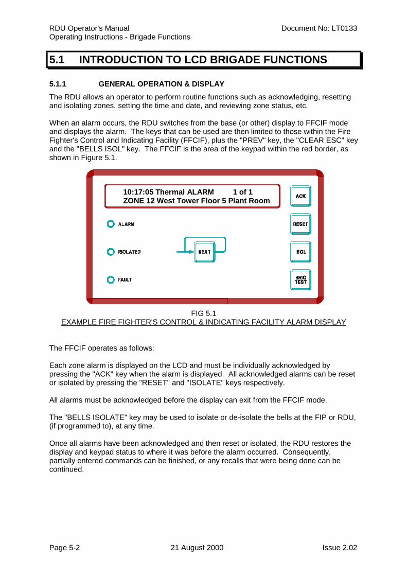
RDU Operator's Manual Document No: LT0133Operating Instructions - Brigade Functions
Page 5-2 21 August 2000 Issue 2.02
5.1 INTRODUCTION TO LCD BRIGADE FUNCTIONS
5.1.1 GENERAL OPERATION & DISPLAYThe RDU allows an operator to perform routine functions such as acknowledging, resettingand isolating zones, setting the time and date, and reviewing zone status, etc.
When an alarm occurs, the RDU switches from the base (or other) display to FFCIF modeand displays the alarm. The keys that can be used are then limited to those within the FireFighter's Control and Indicating Facility (FFCIF), plus the "PREV" key, the "CLEAR ESC" keyand the "BELLS ISOL" key. The FFCIF is the area of the keypad within the red border, asshown in Figure 5.1.
10:17:05 Thermal ALARM 1 of 1 ZONE 12 West Tower Floor 5 Plant Room
FIG 5.1EXAMPLE FIRE FIGHTER'S CONTROL & INDICATING FACILITY ALARM DISPLAY
The FFCIF operates as follows:
Each zone alarm is displayed on the LCD and must be individually acknowledged bypressing the "ACK" key when the alarm is displayed. All acknowledged alarms can be resetor isolated by pressing the "RESET" and "ISOLATE" keys respectively.
All alarms must be acknowledged before the display can exit from the FFCIF mode.
The "BELLS ISOLATE" key may be used to isolate or de-isolate the bells at the FIP or RDU,(if programmed to), at any time.
Once all alarms have been acknowledged and then reset or isolated, the RDU restores thedisplay and keypad status to where it was before the alarm occurred. Consequently,partially entered commands can be finished, or any recalls that were being done can becontinued.
Document No: LT0133 RDU Operator's ManualOperating Instructions - Brigade Functions
Issue 2.02 21 August 2000 Page 5-3
5.1.2 FFCIF OPERATIONWhen the RDU is displaying an alarm the LCD shows the following information:
(i) The time at which the alarm occurred.(ii) The zone alarm type.(iii) Whether the alarm is acknowledged or not (Figure 5.1 shows an unacknowledged
alarm).(iv) The total number of alarms and the sequence number of the currently displayed
alarm.(v) The zone number and location.
The RDU maintains a list of alarms in the order in which they occurred. In the absence ofoperator intervention, the LCD display will show the first alarm. All alarms in the list can beviewed, one by one, by pressing the "NEXT" or "PREV" keys.
Each alarm can be individually acknowledged when it is displayed by pressing the "ACK"key. The text "ACKD" appears on the display whenever an acknowledged alarm is viewed.
Once an alarm has been acknowledged, it can be removed from the alarms list by:
(i) Pressing the "RESET" key - all acknowledged alarms are RESET, and removed fromthe list; or
(ii) Pressing the "ISOLATE" key - all acknowledged alarms are ISOLATED, andremoved from the list; or
(iii) The alarm condition being cleared from a non-latching detector on a non-latchingzone.
After all alarms have been acknowledged, pressing the "CLEAR ESC" key will exit from theFFCIF display even if there are still zones in alarm. After exiting, the FFCIF display can berecalled by using the RECALL Alarm List command from the base display.
5.2 SILENCING THE INTERNAL SOUNDER
5.2.1 FUNCTIONPressing any key will silence the internal sounder, ie, cancel the pulsing alarm tone, steadyfault tone, or rapid pulsing test fail tone.
Note that the key pressed will still be processed as if the sounder was not on. Therefore, itis safest to use the "CLEAR ESC" key to silence the sounder and not to use the "ACK" keyfor faults or other states which are not automatically displayed.
Note: The alarm bells at this RDU (FP0558 only) are silenced by a bells isolate commandat either the FIP or RDU (according to programming).
RDU Operator's Manual Document No: LT0133Operating Instructions - Brigade Functions
Page 5-4 21 August 2000 Issue 2.02
5.2.2 OPERATING SEQUENCE
Press "CLEAR ESC" key once.- The internal sounder silences.
NOTE:
If a key sequence was being entered, it may be necessary to re-enter number information orthe last command as the "CLEAR ESC" key will, in addition to silencing the buzzer, eitherstep back through the menu or clear any number entry sequence that had been started.
If all zone alarms are acknowledged, pressing the "CLEAR ESC" key will result in the LCDexiting FFCIF mode. It can be re-entered by use of the Recall command by pressing the"RECALL" key when the base display is shown and selecting the Alarms List option (option2).
5.3 BELL ISOLATE OR DE-ISOLATE
5.3.1 FUNCTIONThe "BELLS ISOL" key may be used at any time to isolate or de-isolate the bells at either theFIP or at this RDU according to what the RDU is programmed for. The "Bells Isolated" LEDshows the current isolated status of the bells at either the FIP or the RDU (also refer toSection 8.2.1 ). For an FP0559 RDU (which does not have its own bells relay), the "BELLSISOL" key may be used to isolate or de-isolate the FIP bells if programmed to.
5.4 ACKNOWLEDGE ZONES IN ALARM
5.4.1 FUNCTIONIn FFCIF mode, pressing the "ACK" key performs the following functions:
(a) The displayed alarm is acknowledged.
(b) The pulsing internal sounder is silenced.
5.4.2 OPERATING SEQUENCEPress "ACK" key once:
- Internal sounder will be silenced.
- LCD displays "ACKD" for the currently displayed alarm.
- If there are no more unacknowledged alarms in the system, the ALARM LEDgoes steady.
- Where fitted, the flashing red "ALM" LED indicator for the zone goes steady.
Document No: LT0133 RDU Operator's ManualOperating Instructions - Brigade Functions
Issue 2.02 21 August 2000 Page 5-5
OPERATING SEQUENCE (CONTINUED)
NOTES:
(a) Subsequent non-isolated zone ALARMS or FAULTS on the system will re-operatethe indicators, and sounder, as appropriate.
(b) If an unacknowledged FAULT condition existed before the alarm then the sounderwill still be silenced. However, the FAULT LED will be ON, indicating the presence ofa zone or relay fault.
5.5 RESET ACKNOWLEDGED ZONES IN ALARM
5.5.1 FUNCTIONIn FFCIF mode pressing the "RESET" key performs the following functions for allacknowledged zones in the alarm list.
(a) RESETS all acknowledged zone(s).(b) Silences the internal sounder.(c) The acknowledged zone alarms are removed from the alarm list.(d) ( FP0558 only ) If no more un-isolated alarms exist, the bells, ancillary and Brigade
Alarm relays will turn OFF, if they were ON.
5.5.2 OPERATING SEQUENCEPress "RESET" key once:
- LCD displays "Resetting all acknowledged alarms".- All acknowledged zones in the alarm list will be reset.- Where fitted, all acknowledged (steady) red alarm LED indicators will be
turned OFF.- The internal sounder will be silenced.- ( FP0558 only ) If there are no more unisolated zones in alarm then the
Brigade alarm relay will de-energise and the Local Bells will be silenced.
NOTES:
(a) If the alarm condition on the zone circuit has not been removed, then the zone alarmindicators and Local Bells will be re-activated (if not isolated), and a new zone alarmwill be put into the alarm list.
(b) Pressing "RESET" in the FFCIF mode has no effect on isolated zones or zones inAuto-Reset mode, as they are unlikely to be in the alarm list.
(c) This command option is not available if the RDU is configured forfor one of the mimic type modes of operation (eg. Non-LCD Mimic, Type 2 Mimic,Type 3 Mimic). This is because mimics cannot control the FIP that they areconnected to.
RDU Operator's Manual Document No: LT0133Operating Instructions - Brigade Functions
Page 5-6 21 August 2000 Issue 2.02
5.6 ISOLATE ACKNOWLEDGED ZONES IN ALARM
5.6.1 FUNCTIONIn FFCIF mode pressing the "ISOL" key performs the following functions for allacknowledged zones in the alarm list.
(a) ISOLATES all acknowledged zones in the alarm list.(b) Silences any internal sounder condition.(c) The acknowledged zone alarms are removed from the alarm list.(d) If there are no more unisolated zones in alarm, ( FP0558 only) the Brigade Alarm
relay, Ancillary relays and Bells will turn off.
5.6.2 OPERATING SEQUENCEPress "ISOL" key once:
- The acknowledged zones in the alarm list will be isolated - shown by the corresponding amber "ISOLATED" LED indicator turning ON.
- The internal sounder, if on, will be silenced.
- ( FP0558 only ) The Local bells (if any) will be silenced so long as all alarms are isolated, ie there are no unacknowledged alarms.
NOTES:
(a) Subsequent non-isolated zone ALARMS on the system will re-operate the alarmindications, alarm sounder and local bells.
(b) Subsequent non-isolated zone FAULTS on the system will operate the faultindication and steady fault sounder.
(c) To DE-ISOLATE alarm zones, FFCIF mode must be exited and the zone selected forde-isolation. Refer to the Exiting FFCIF mode section in this chapter and theIndividual Zone Isolating/De-Isolating section in Chapter 7. Note that it is not possibleto de-isolate zones from an RDU configured for Non-LCD mode of operation.
(d) This command option is not available if the RDU is configured for one of the mimic type modes of operation (eg. Non-LCD Mimic, Type 2 Mimic, Type 3 Mimic). This is because mimics cannot control the FIP that they are connected to.
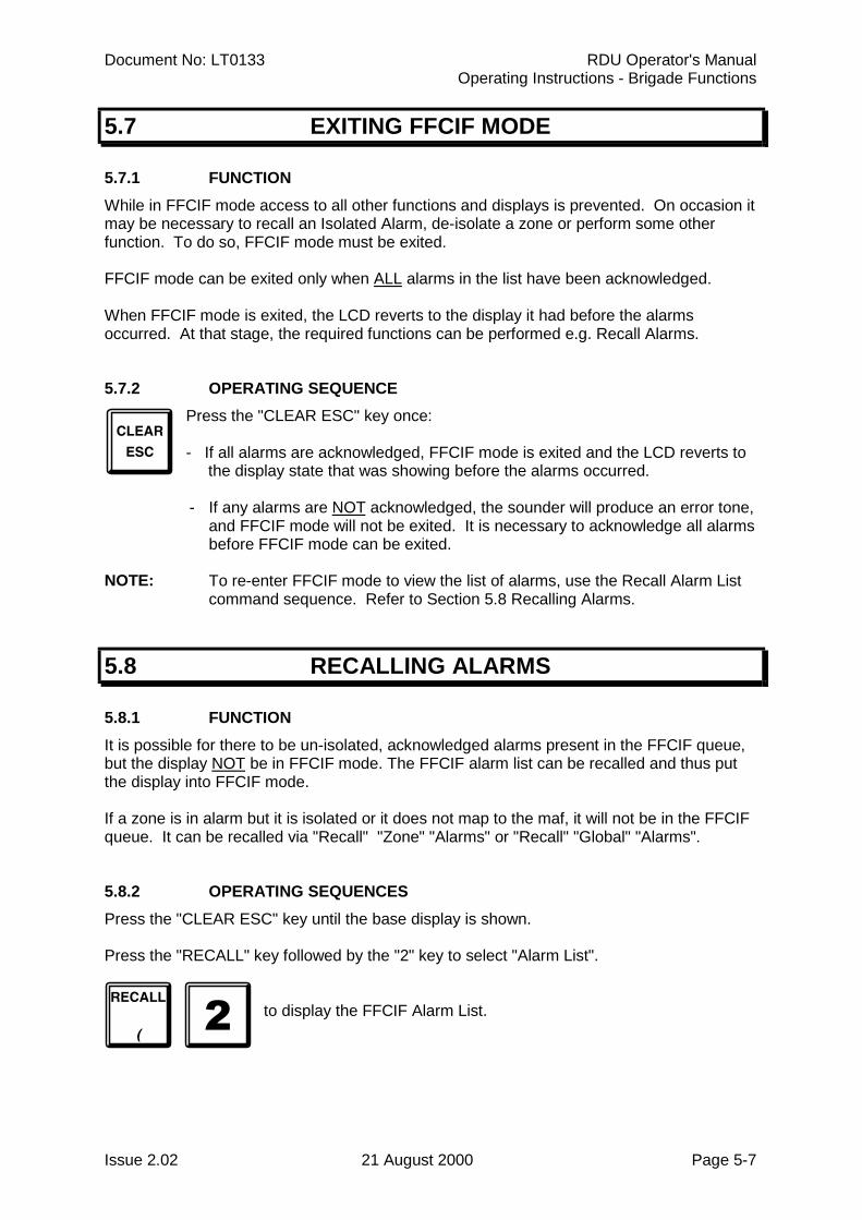
Document No: LT0133 RDU Operator's ManualOperating Instructions - Brigade Functions
Issue 2.02 21 August 2000 Page 5-7
5.7 EXITING FFCIF MODE
5.7.1 FUNCTIONWhile in FFCIF mode access to all other functions and displays is prevented. On occasion itmay be necessary to recall an Isolated Alarm, de-isolate a zone or perform some otherfunction. To do so, FFCIF mode must be exited.
FFCIF mode can be exited only when ALL alarms in the list have been acknowledged.
When FFCIF mode is exited, the LCD reverts to the display it had before the alarmsoccurred. At that stage, the required functions can be performed e.g. Recall Alarms.
5.7.2 OPERATING SEQUENCEPress the "CLEAR ESC" key once:
- If all alarms are acknowledged, FFCIF mode is exited and the LCD reverts to the display state that was showing before the alarms occurred.
- If any alarms are NOT acknowledged, the sounder will produce an error tone, and FFCIF mode will not be exited. It is necessary to acknowledge all alarmsbefore FFCIF mode can be exited.
NOTE: To re-enter FFCIF mode to view the list of alarms, use the Recall Alarm Listcommand sequence. Refer to Section 5.8 Recalling Alarms.
5.8 RECALLING ALARMS
5.8.1 FUNCTIONIt is possible for there to be un-isolated, acknowledged alarms present in the FFCIF queue,but the display NOT be in FFCIF mode. The FFCIF alarm list can be recalled and thus putthe display into FFCIF mode.
If a zone is in alarm but it is isolated or it does not map to the maf, it will not be in the FFCIFqueue. It can be recalled via "Recall" "Zone" "Alarms" or "Recall" "Global" "Alarms".
5.8.2 OPERATING SEQUENCESPress the "CLEAR ESC" key until the base display is shown.
Press the "RECALL" key followed by the "2" key to select "Alarm List".
to display the FFCIF Alarm List.
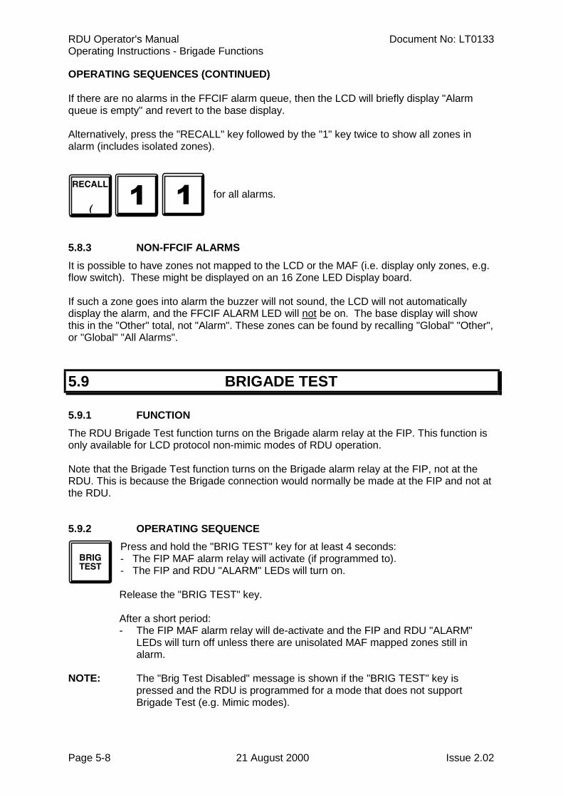
RDU Operator's Manual Document No: LT0133Operating Instructions - Brigade Functions
Page 5-8 21 August 2000 Issue 2.02
OPERATING SEQUENCES (CONTINUED)
If there are no alarms in the FFCIF alarm queue, then the LCD will briefly display "Alarmqueue is empty" and revert to the base display.
Alternatively, press the "RECALL" key followed by the "1" key twice to show all zones inalarm (includes isolated zones).
for all alarms.
5.8.3 NON-FFCIF ALARMSIt is possible to have zones not mapped to the LCD or the MAF (i.e. display only zones, e.g.flow switch). These might be displayed on an 16 Zone LED Display board.
If such a zone goes into alarm the buzzer will not sound, the LCD will not automaticallydisplay the alarm, and the FFCIF ALARM LED will not be on. The base display will showthis in the "Other" total, not "Alarm". These zones can be found by recalling "Global" "Other",or "Global" "All Alarms".
5.9 BRIGADE TEST
5.9.1 FUNCTIONThe RDU Brigade Test function turns on the Brigade alarm relay at the FIP. This function isonly available for LCD protocol non-mimic modes of RDU operation.
Note that the Brigade Test function turns on the Brigade alarm relay at the FIP, not at theRDU. This is because the Brigade connection would normally be made at the FIP and not atthe RDU.
5.9.2 OPERATING SEQUENCEPress and hold the "BRIG TEST" key for at least 4 seconds:- The FIP MAF alarm relay will activate (if programmed to).- The FIP and RDU "ALARM" LEDs will turn on.
Release the "BRIG TEST" key.
After a short period:- The FIP MAF alarm relay will de-activate and the FIP and RDU "ALARM"
LEDs will turn off unless there are unisolated MAF mapped zones still inalarm.
NOTE: The "Brig Test Disabled" message is shown if the "BRIG TEST" key ispressed and the RDU is programmed for a mode that does not supportBrigade Test (e.g. Mimic modes).
Document No: LT0133 RDU Operator's ManualOperating Instructions - System Functions
Issue 2.02 21 August 2000 Page 6-1
CHAPTER 6OPERATING INSTRUCTIONS
- SYSTEM FUNCTIONS
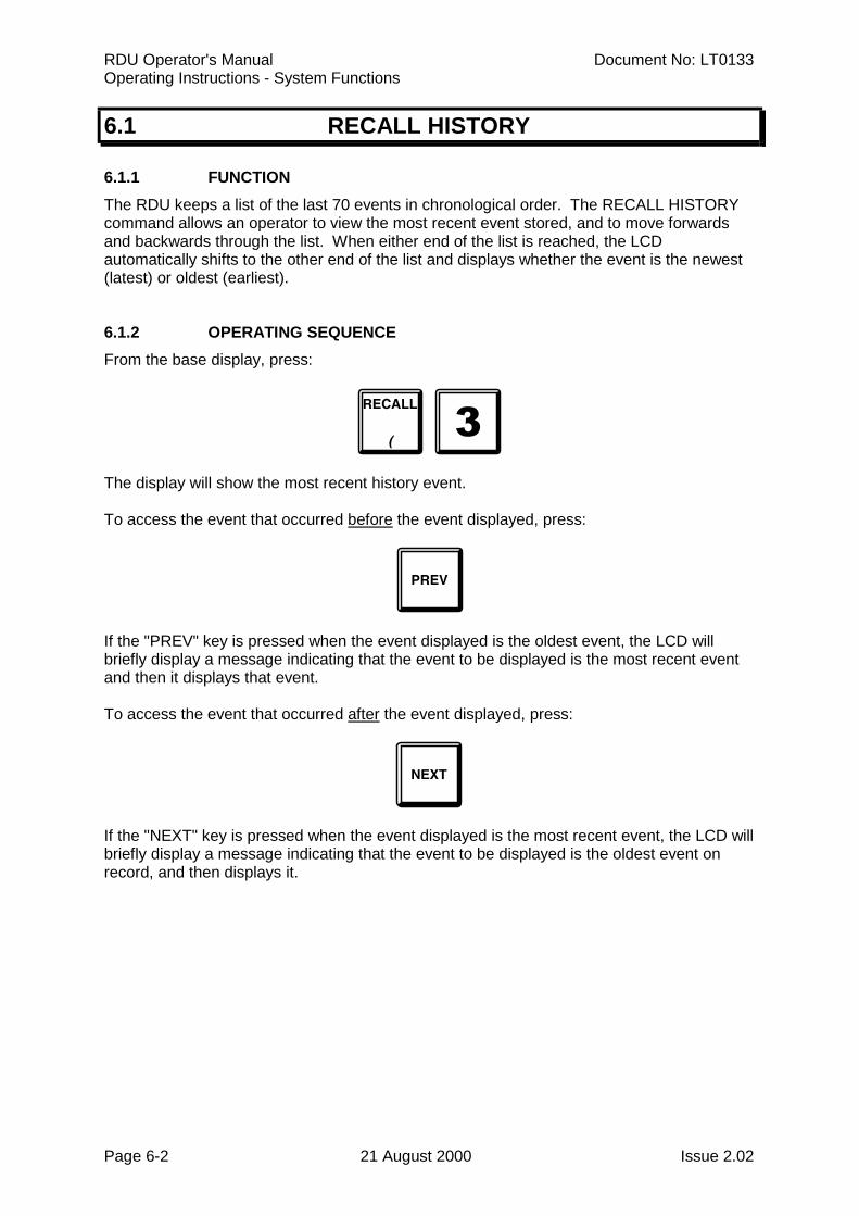
RDU Operator's Manual Document No: LT0133Operating Instructions - System Functions
Page 6-2 21 August 2000 Issue 2.02
6.1 RECALL HISTORY
6.1.1 FUNCTIONThe RDU keeps a list of the last 70 events in chronological order. The RECALL HISTORYcommand allows an operator to view the most recent event stored, and to move forwardsand backwards through the list. When either end of the list is reached, the LCDautomatically shifts to the other end of the list and displays whether the event is the newest(latest) or oldest (earliest).
6.1.2 OPERATING SEQUENCEFrom the base display, press:
The display will show the most recent history event.
To access the event that occurred before the event displayed, press:
If the "PREV" key is pressed when the event displayed is the oldest event, the LCD willbriefly display a message indicating that the event to be displayed is the most recent eventand then it displays that event.
To access the event that occurred after the event displayed, press:
If the "NEXT" key is pressed when the event displayed is the most recent event, the LCD willbriefly display a message indicating that the event to be displayed is the oldest event onrecord, and then displays it.
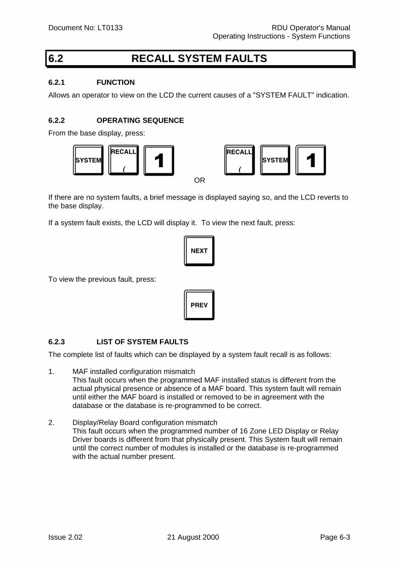
Document No: LT0133 RDU Operator's ManualOperating Instructions - System Functions
Issue 2.02 21 August 2000 Page 6-3
6.2 RECALL SYSTEM FAULTS
6.2.1 FUNCTIONAllows an operator to view on the LCD the current causes of a "SYSTEM FAULT" indication.
6.2.2 OPERATING SEQUENCEFrom the base display, press:
OR
If there are no system faults, a brief message is displayed saying so, and the LCD reverts tothe base display.
If a system fault exists, the LCD will display it. To view the next fault, press:
To view the previous fault, press:
6.2.3 LIST OF SYSTEM FAULTSThe complete list of faults which can be displayed by a system fault recall is as follows:
1. MAF installed configuration mismatchThis fault occurs when the programmed MAF installed status is different from theactual physical presence or absence of a MAF board. This system fault will remainuntil either the MAF board is installed or removed to be in agreement with thedatabase or the database is re-programmed to be correct.
2. Display/Relay Board configuration mismatchThis fault occurs when the programmed number of 16 Zone LED Display or RelayDriver boards is different from that physically present. This System fault will remainuntil the correct number of modules is installed or the database is re-programmedwith the actual number present.
RDU Operator's Manual Document No: LT0133Operating Instructions - System Functions
Page 6-4 21 August 2000 Issue 2.02
SYSTEM FAULT RECALL FAULT LIST (CONTINUED)
3. EEPROM database checksum error. The panel is inoperational if this fault ispresent.
4. EEPROM database version errorThis fault condition means that the EEPROM database checksum is correct but thedatabase is an old version with a format which cannot be used.
All zone status processing is disabled when this fault is present and the panel isinoperational.
5. EEPROM write failThis fault will occur if a write to EEPROM database memory during program modefails.
6. Banked EEPROM error. There has been an error in reading or writing to the bankedportion of EEPROM. The panel is inoperational if this fault is present.
7. All zones isolatedThis fault will occur if all zones (mapped to MAF) are isolated. This can be inhibitedwith an option in programming, but doing so may contravene AS1603.4.
8. Scan FailThis fault indicates communication with the FIP has failed. The RDU is inoperable ifthis fault is present.
9. Keypad disconnected. The loom between the keypad and Controller/Display Bd isdisconnected/faulty.
10. Battery failedThis fault means that the DC supply has fallen to 21 volts or below. Either both mainsand the battery voltage have failed ( FP0558 only ) or the DC line power from the FIP( FP0559 ) has fallen to 21 volts or below. When this system fault is present theCharger/Batt fault LED comes on and MAF configured RDUs de-energise thestandby relay and processing of all MAF board inputs stops and relay outputs areheld in their current state.
11. RAM write read faultA read/write test of main RAM has failed. This can occur during System and RemoteTest.
12. EPROM CRC errorA checksum calculation of EPROM memory has failed. This can occur duringSystem and Auto Test.
13. LED Display Board FaultThere is a fault with a LED Display or Relay Driver board. This can occur if either thewrong number of boards are installed or there is a break in the cabling betweenboards.
14. LCD display faultA fault has occurred with the 80 character LCD. This can occur at startup or duringan LCD test.
Document No: LT0133 RDU Operator's ManualOperating Instructions - System Functions
Issue 2.02 21 August 2000 Page 6-5
SYSTEM FAULT RECALL FAULT LIST (CONTINUED)
15. Shift register bus faultThis error indicates a fault with the bus connecting the Controller with the MAF/PSU.It may be caused by a break or short in the flat ribbon cable (e.g. bd unplugged) or bytemporary noise or by a circuit board fault.
When this fault occurs all outputs will be held in their current state and all processingof inputs will stop until the fault clears. If the fault does clear, processing of outputsand inputs will resume automatically.
16. Battery lowThis occurs in New Zealand mode operation only. It indicates that the supply voltagehas fallen below 24.4 volts to warn that the battery is losing charge. A battery failevent will occur at 21 volts.
17. Clock crystal timebase check fail.This error message occurs only at startup and indicates the frequency of the clockchip on the Controller is out of tolerance to the microprocessor. The Controller willrestart and try the test again.
18. Clock register write read fail.A test of the Controller time/date clock registers has failed. The Controller will restartand try the test again.
SYSTEM FAULTS MAF CONFIGURED RDU ( FP0558 ) Only
19. Fuse blownOne of the fuses on the MAF board has blown.
20. Charger faultA battery charger fault has occurred.
21. Mains failNote: A mains fail is not a true system fault and does not cause the "SYSTEMFAULT" LED to turn on.
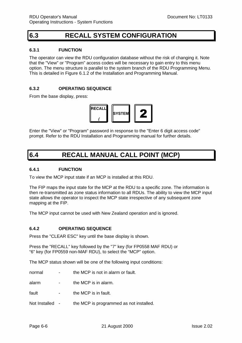
RDU Operator's Manual Document No: LT0133Operating Instructions - System Functions
Page 6-6 21 August 2000 Issue 2.02
6.3 RECALL SYSTEM CONFIGURATION
6.3.1 FUNCTIONThe operator can view the RDU configuration database without the risk of changing it. Notethat the "View" or "Program" access codes will be necessary to gain entry to this menuoption. The menu structure is parallel to the system branch of the RDU Programming Menu.This is detailed in Figure 6.1.2 of the Installation and Programming Manual.
6.3.2 OPERATING SEQUENCEFrom the base display, press:
Enter the "View" or "Program" password in response to the "Enter 6 digit access code"prompt. Refer to the RDU Installation and Programming manual for further details.
6.4 RECALL MANUAL CALL POINT (MCP)
6.4.1 FUNCTIONTo view the MCP input state if an MCP is installed at this RDU.
The FIP maps the input state for the MCP at the RDU to a specific zone. The information isthen re-transmitted as zone status information to all RDUs. The ability to view the MCP inputstate allows the operator to inspect the MCP state irrespective of any subsequent zonemapping at the FIP.
The MCP input cannot be used with New Zealand operation and is ignored.
6.4.2 OPERATING SEQUENCEPress the "CLEAR ESC" key until the base display is shown.
Press the "RECALL" key followed by the "7" key (for FP0558 MAF RDU) or“6" key (for FP0559 non-MAF RDU), to select the “MCP” option.
The MCP status shown will be one of the following input conditions:
normal - the MCP is not in alarm or fault.
alarm - the MCP is in alarm.
fault - the MCP is in fault.
Not Installed - the MCP is programmed as not installed.
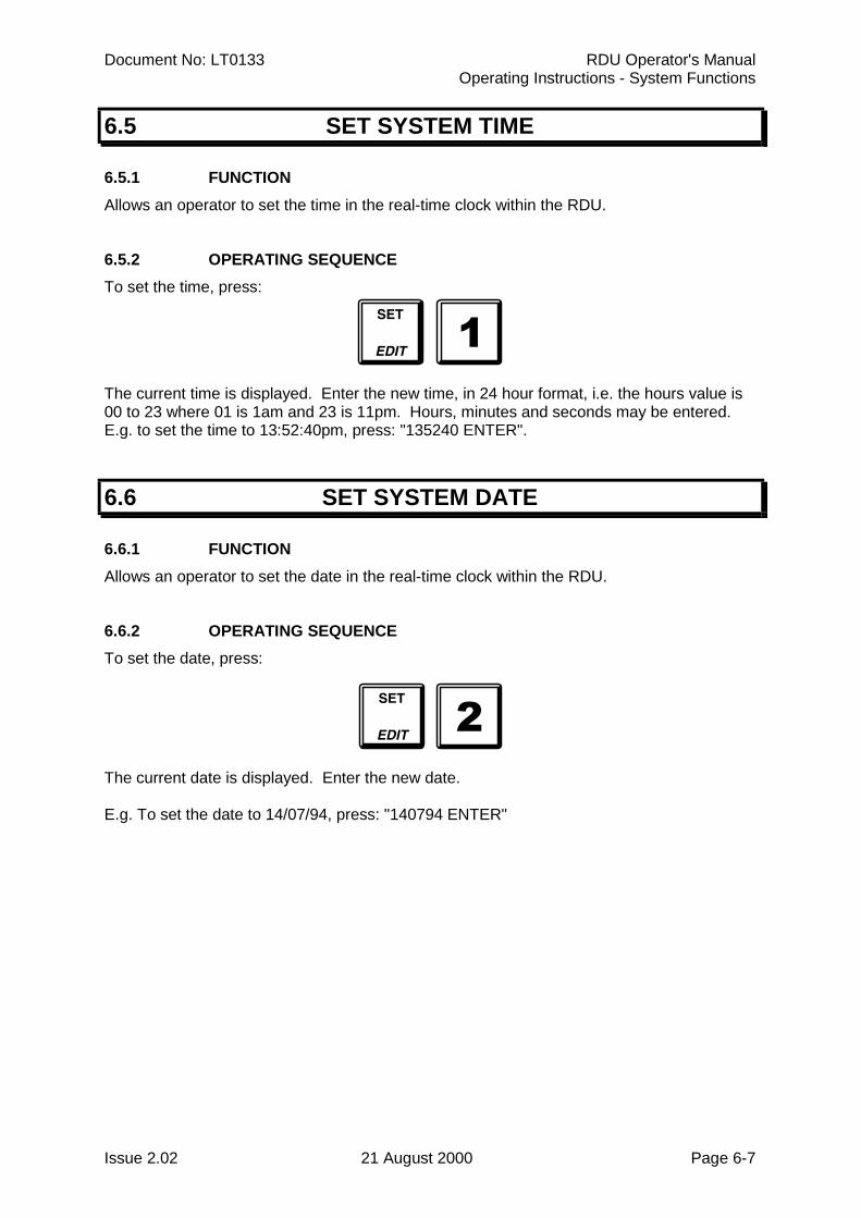
Document No: LT0133 RDU Operator's ManualOperating Instructions - System Functions
Issue 2.02 21 August 2000 Page 6-7
6.5 SET SYSTEM TIME
6.5.1 FUNCTIONAllows an operator to set the time in the real-time clock within the RDU.
6.5.2 OPERATING SEQUENCETo set the time, press:
The current time is displayed. Enter the new time, in 24 hour format, i.e. the hours value is00 to 23 where 01 is 1am and 23 is 11pm. Hours, minutes and seconds may be entered.E.g. to set the time to 13:52:40pm, press: "135240 ENTER".
6.6 SET SYSTEM DATE
6.6.1 FUNCTIONAllows an operator to set the date in the real-time clock within the RDU.
6.6.2 OPERATING SEQUENCETo set the date, press:
The current date is displayed. Enter the new date.
E.g. To set the date to 14/07/94, press: "140794 ENTER"
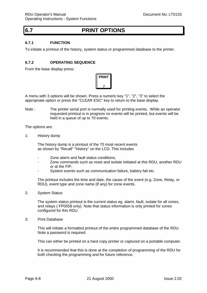
RDU Operator's Manual Document No: LT0133Operating Instructions - System Functions
Page 6-8 21 August 2000 Issue 2.02
6.7 PRINT OPTIONS
6.7.1 FUNCTIONTo initiate a printout of the history, system status or programmed database to the printer.
6.7.2 OPERATING SEQUENCEFrom the base display press:
A menu with 3 options will be shown. Press a numeric key "1", "2", "3" to select theappropriate option or press the "CLEAR ESC" key to return to the base display.
Note : The printer serial port is normally used for printing events. While an operatorrequested printout is in progress no events will be printed, but events will beheld in a queue of up to 70 events.
The options are:
1: History dump
The history dump is a printout of the 70 most recent eventsas shown by "Recall" "History" on the LCD. This includes
- Zone alarm and fault status conditions, - Zone commands such as reset and isolate initiated at this RDU, another RDU
or at the FIP,- System events such as communication failure, battery fail etc.
The printout includes the time and date, the cause of the event (e.g. Zone, Relay, or RDU), event type and zone name (if any) for zone events.
2: System Status
The system status printout is the current status eg. alarm, fault, isolate for all zones, and relays ( FP0558 only). Note that status information is only printed for zones configured for this RDU.
3: Print Database
This will initiate a formatted printout of the entire programmed database of the RDU.Note a password is required.
This can either be printed on a hard copy printer or captured on a portable computer.
It is recommended that this is done at the completion of programming of the RDU forboth checking the programming and for future reference.
Document No: LT0133 RDU Operator's ManualOperating Instructions - System Functions
Issue 2.02 21 August 2000 Page 6-9
OPERATING SEQUENCE (CONTINUED)
While a print operation is in progress the display will show
"Print in progress. Press RESET to cancel".
Pressing the "RESET" key will terminate the printout immediately. Pressing the "CLEARESC" key while the printout is in progress will return to the base display and the printout willcontinue.
6.8 RECALL DATABASE CRC
To check the validity of the RDU database press the RECALL key from the base display andselect either option 8 "CRC" (for FP0559 non-MAF RDU) or option 9 “CRC” (for FP0558MAF RDU). The value of the current database CRC will be displayed as 4 hex digits and thedate and time that the database was last changed will also be shown. The databasechecksum will be recalculated and verified.
This can be done as part of weekly or monthly system testing to check that the database hasnot been modified without authorisation. I.e. after an RDU has been completely programmedand commissioned, the recall CRC function should be done and the CRC and time and dateshould be recorded for future checking and these values should be updated every time thedatabase is modified by an authorised user.

RDU Operator's Manual Document No: LT0133Operating Instructions - System Functions
Page 6-10 21 August 2000 Issue 2.02
THIS PAGE LEFT INTENTIONALLY BLANK
Document No: LT0133 RDU Operator's ManualOperating Instructions - Zone Functions
Issue 2.02 21 August 2000 Page 7-1
CHAPTER 7OPERATING INSTRUCTIONS
- ZONE FUNCTIONS
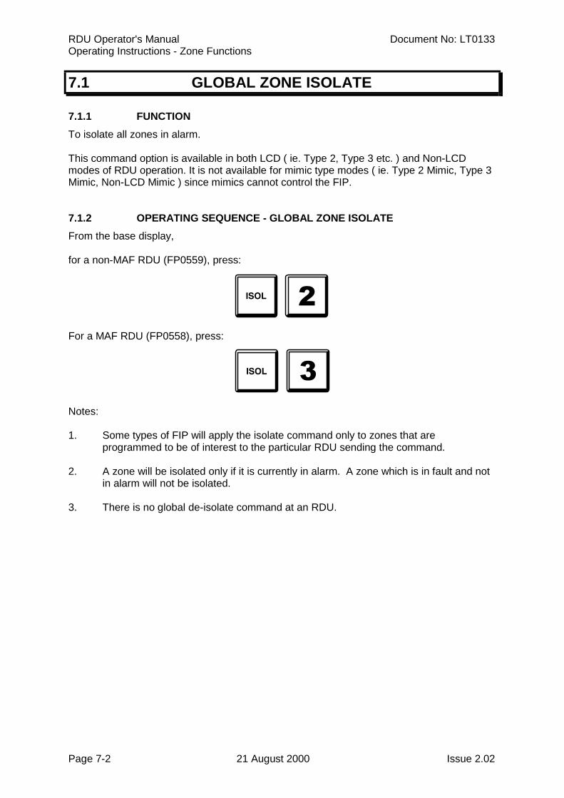
RDU Operator's Manual Document No: LT0133Operating Instructions - Zone Functions
Page 7-2 21 August 2000 Issue 2.02
7.1 GLOBAL ZONE ISOLATE
7.1.1 FUNCTIONTo isolate all zones in alarm.
This command option is available in both LCD ( ie. Type 2, Type 3 etc. ) and Non-LCDmodes of RDU operation. It is not available for mimic type modes ( ie. Type 2 Mimic, Type 3Mimic, Non-LCD Mimic ) since mimics cannot control the FIP.
7.1.2 OPERATING SEQUENCE - GLOBAL ZONE ISOLATEFrom the base display,
for a non-MAF RDU (FP0559), press:
For a MAF RDU (FP0558), press:
Notes:
1. Some types of FIP will apply the isolate command only to zones that areprogrammed to be of interest to the particular RDU sending the command.
2. A zone will be isolated only if it is currently in alarm. A zone which is in fault and notin alarm will not be isolated.
3. There is no global de-isolate command at an RDU.
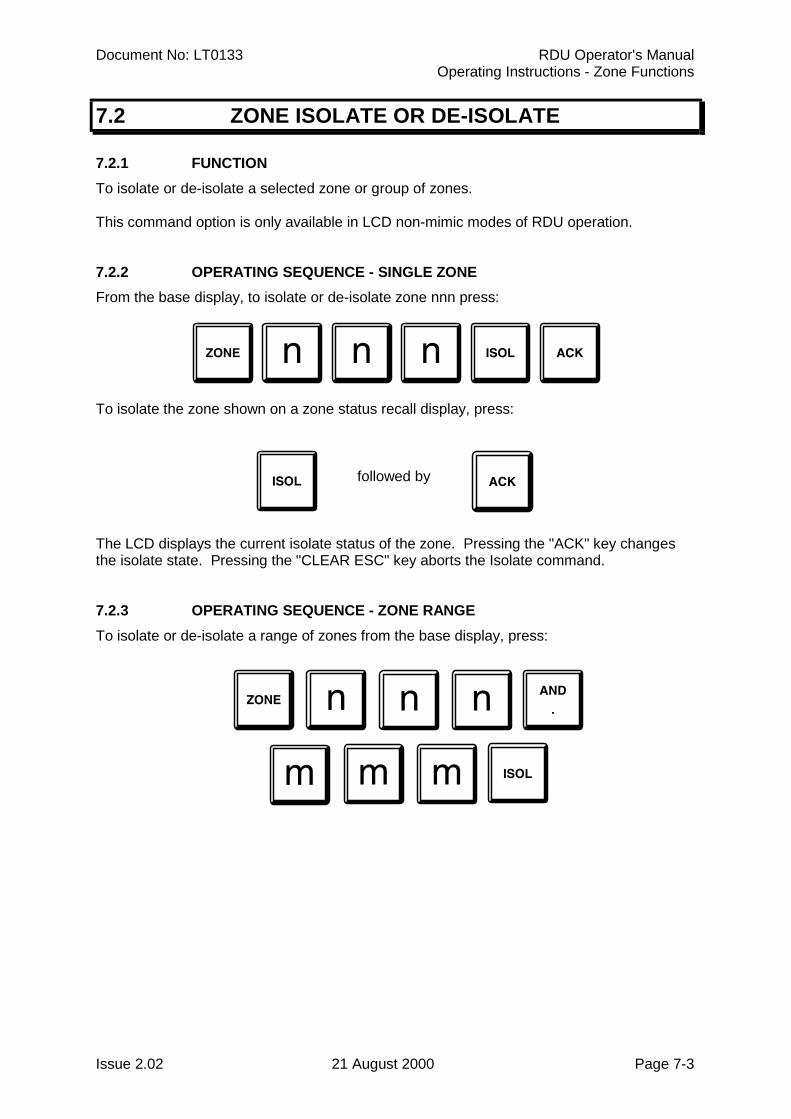
Document No: LT0133 RDU Operator's ManualOperating Instructions - Zone Functions
Issue 2.02 21 August 2000 Page 7-3
7.2 ZONE ISOLATE OR DE-ISOLATE
7.2.1 FUNCTIONTo isolate or de-isolate a selected zone or group of zones.
This command option is only available in LCD non-mimic modes of RDU operation.
7.2.2 OPERATING SEQUENCE - SINGLE ZONEFrom the base display, to isolate or de-isolate zone nnn press:
To isolate the zone shown on a zone status recall display, press:
followed by
The LCD displays the current isolate status of the zone. Pressing the "ACK" key changesthe isolate state. Pressing the "CLEAR ESC" key aborts the Isolate command.
7.2.3 OPERATING SEQUENCE - ZONE RANGETo isolate or de-isolate a range of zones from the base display, press:
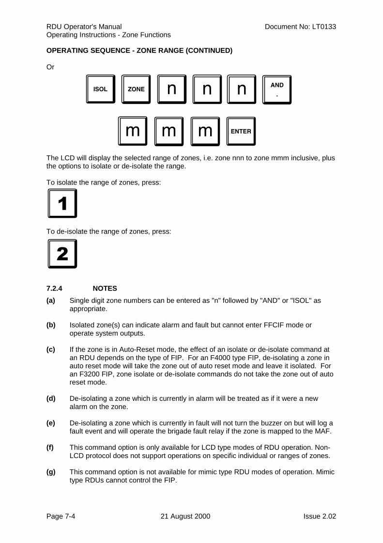
RDU Operator's Manual Document No: LT0133Operating Instructions - Zone Functions
Page 7-4 21 August 2000 Issue 2.02
OPERATING SEQUENCE - ZONE RANGE (CONTINUED)
Or
The LCD will display the selected range of zones, i.e. zone nnn to zone mmm inclusive, plusthe options to isolate or de-isolate the range.
To isolate the range of zones, press:
To de-isolate the range of zones, press:
7.2.4 NOTES(a) Single digit zone numbers can be entered as "n" followed by "AND" or "ISOL" as
appropriate.
(b) Isolated zone(s) can indicate alarm and fault but cannot enter FFCIF mode oroperate system outputs.
(c) If the zone is in Auto-Reset mode, the effect of an isolate or de-isolate command atan RDU depends on the type of FIP. For an F4000 type FIP, de-isolating a zone inauto reset mode will take the zone out of auto reset mode and leave it isolated. Foran F3200 FIP, zone isolate or de-isolate commands do not take the zone out of autoreset mode.
(d) De-isolating a zone which is currently in alarm will be treated as if it were a newalarm on the zone.
(e) De-isolating a zone which is currently in fault will not turn the buzzer on but will log afault event and will operate the brigade fault relay if the zone is mapped to the MAF.
(f) This command option is only available for LCD type modes of RDU operation. Non-LCD protocol does not support operations on specific individual or ranges of zones.
(g) This command option is not available for mimic type RDU modes of operation. Mimictype RDUs cannot control the FIP.
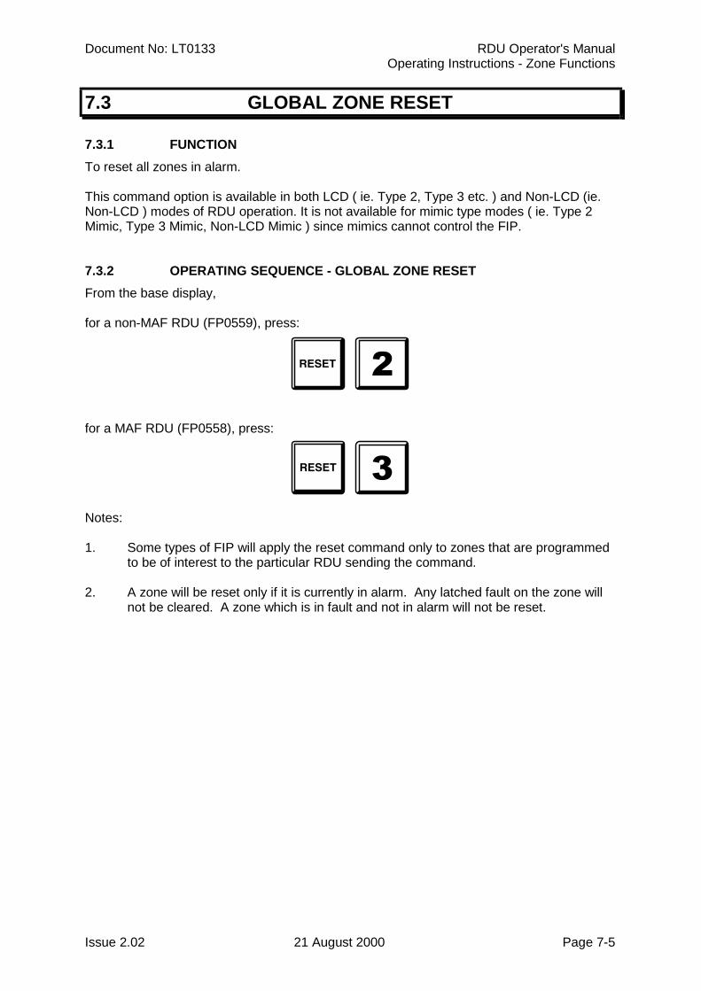
Document No: LT0133 RDU Operator's ManualOperating Instructions - Zone Functions
Issue 2.02 21 August 2000 Page 7-5
7.3 GLOBAL ZONE RESET
7.3.1 FUNCTIONTo reset all zones in alarm.
This command option is available in both LCD ( ie. Type 2, Type 3 etc. ) and Non-LCD (ie.Non-LCD ) modes of RDU operation. It is not available for mimic type modes ( ie. Type 2Mimic, Type 3 Mimic, Non-LCD Mimic ) since mimics cannot control the FIP.
7.3.2 OPERATING SEQUENCE - GLOBAL ZONE RESETFrom the base display,
for a non-MAF RDU (FP0559), press:
for a MAF RDU (FP0558), press:
Notes:
1. Some types of FIP will apply the reset command only to zones that are programmedto be of interest to the particular RDU sending the command.
2. A zone will be reset only if it is currently in alarm. Any latched fault on the zone willnot be cleared. A zone which is in fault and not in alarm will not be reset.
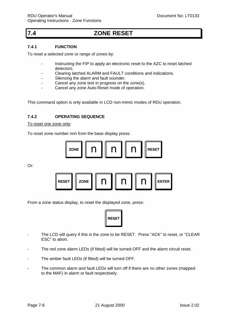
RDU Operator's Manual Document No: LT0133Operating Instructions - Zone Functions
Page 7-6 21 August 2000 Issue 2.02
7.4 ZONE RESET
7.4.1 FUNCTIONTo reset a selected zone or range of zones by:
- Instructing the FIP to apply an electronic reset to the AZC to reset latcheddetectors.
- Clearing latched ALARM and FAULT conditions and indications.- Silencing the alarm and fault sounder.- Cancel any zone test in progress on the zone(s).- Cancel any zone Auto-Reset mode of operation.
This command option is only available in LCD non-mimic modes of RDU operation.
7.4.2 OPERATING SEQUENCETo reset one zone only:
To reset zone number nnn from the base display press:
Or:
From a zone status display, to reset the displayed zone, press:
- The LCD will query if this is the zone to be RESET. Press "ACK" to reset, or "CLEARESC" to abort.
- The red zone alarm LEDs (if fitted) will be turned OFF and the alarm circuit reset.
- The amber fault LEDs (if fitted) will be turned OFF.
- The common alarm and fault LEDs will turn off if there are no other zones (mappedto the MAF) in alarm or fault respectively.
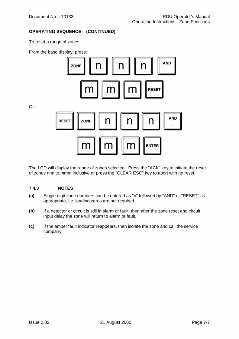
Document No: LT0133 RDU Operator's ManualOperating Instructions - Zone Functions
Issue 2.02 21 August 2000 Page 7-7
OPERATING SEQUENCE (CONTINUED)
To reset a range of zones:
From the base display, press:
Or:
The LCD will display the range of zones selected. Press the "ACK" key to initiate the resetof zones nnn to mmm inclusive or press the "CLEAR ESC" key to abort with no reset.
7.4.3 NOTES(a) Single digit zone numbers can be entered as "n" followed by "AND" or "RESET" as
appropriate, i.e. leading zeros are not required.
(b) If a detector or circuit is still in alarm or fault, then after the zone reset and circuitinput delay the zone will return to alarm or fault.
(c) If the amber fault indicator reappears, then isolate the zone and call the servicecompany.
RDU Operator's Manual Document No: LT0133Operating Instructions - Zone Functions
Page 7-8 21 August 2000 Issue 2.02
7.5 ZONE TEST
7.5.1 FUNCTIONTo perform an alarm test or fault test on a selected zone or range of zones by instructing theFIP to apply an electronic circuit test condition to all circuits mapped to the zone(s).
The command must be enabled with programming. Not all types or versions of FIP are ableto process and execute the zone test commands from the RDU. Also, this command optionis only available in LCD non-mimic modes of RDU operation.
The RDU will not issue a test command for any zone which is not programmed as being ofinterest to the RDU i.e. is not mapped to either an LED or the LCD. Either a single zone at atime or a range of zones simultaneously may be tested. When a range of zones is tested,only zones of interest to the RDU will be tested. The FIP will not carry out the zone test if itcurrently has a system or auto test running or if the zone is already under test. If the testpasses, a fault or alarm will occur on the zone and be indicated at the RDU.
There is no indication at the RDU that a zone test is active on any zone. Also there is noindication at the RDU of any test failure which may occur, other than the failure of the zoneto go into alarm or fault. The FIP will perform the zone test as if the test had been initiated atthe FIP keypad and will log any test fail which occurs. The test may be terminated at anytime with a zone reset command at either the FIP or RDU. The FIP will terminate the testautomatically after approximately three minutes from the start of the test.
Not all types and versions of FIP are able to process and execute zone test commands froman RDU. Also, F4000 panels are not able to test a range of zones - they can only test onezone at a time, but the zone may have multiple circuits mapped to it. FIPs which currentlysupport zone test commands are:
F4000 V2.21 onwards,F3200 V2.00 onwards.
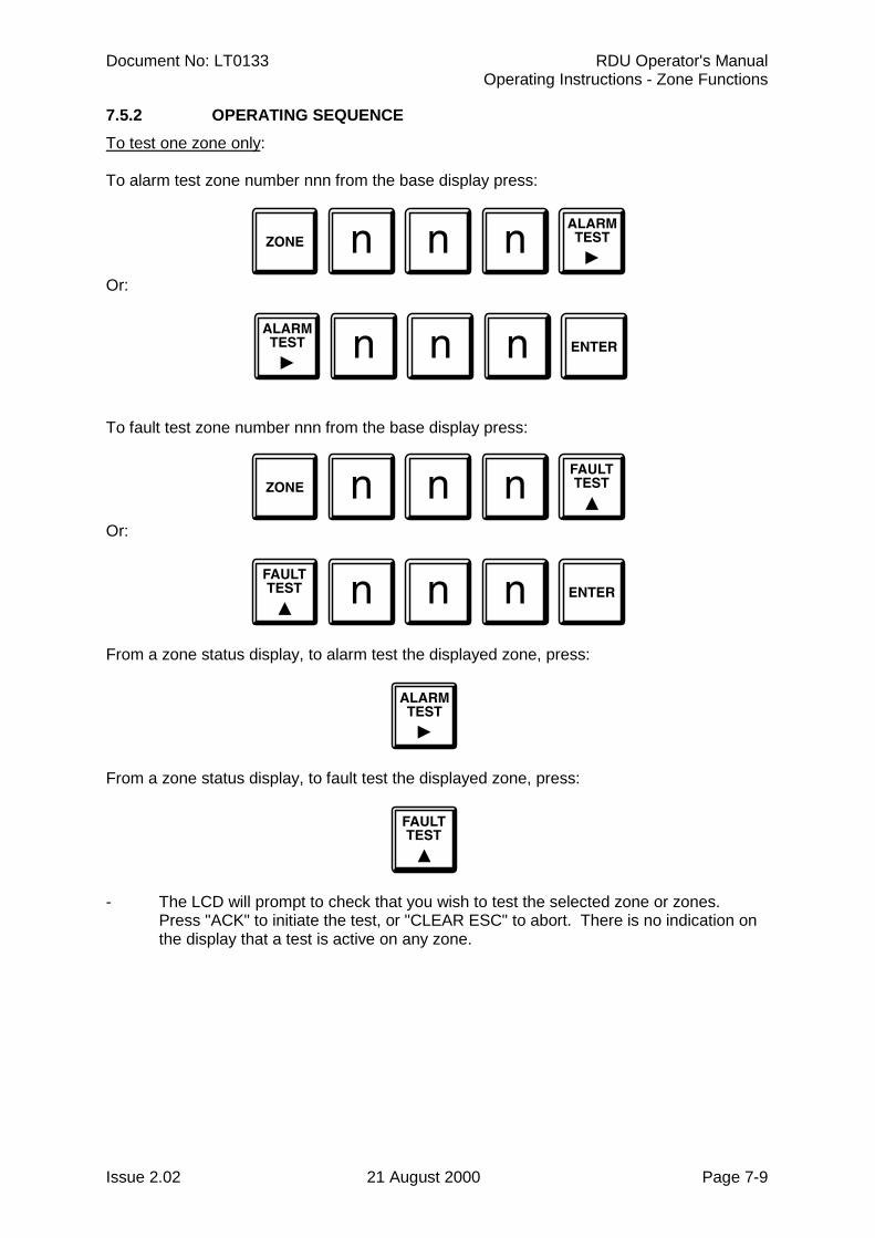
Document No: LT0133 RDU Operator's ManualOperating Instructions - Zone Functions
Issue 2.02 21 August 2000 Page 7-9
7.5.2 OPERATING SEQUENCETo test one zone only:
To alarm test zone number nnn from the base display press:
Or:
To fault test zone number nnn from the base display press:
Or:
From a zone status display, to alarm test the displayed zone, press:
From a zone status display, to fault test the displayed zone, press:
- The LCD will prompt to check that you wish to test the selected zone or zones.Press "ACK" to initiate the test, or "CLEAR ESC" to abort. There is no indication onthe display that a test is active on any zone.
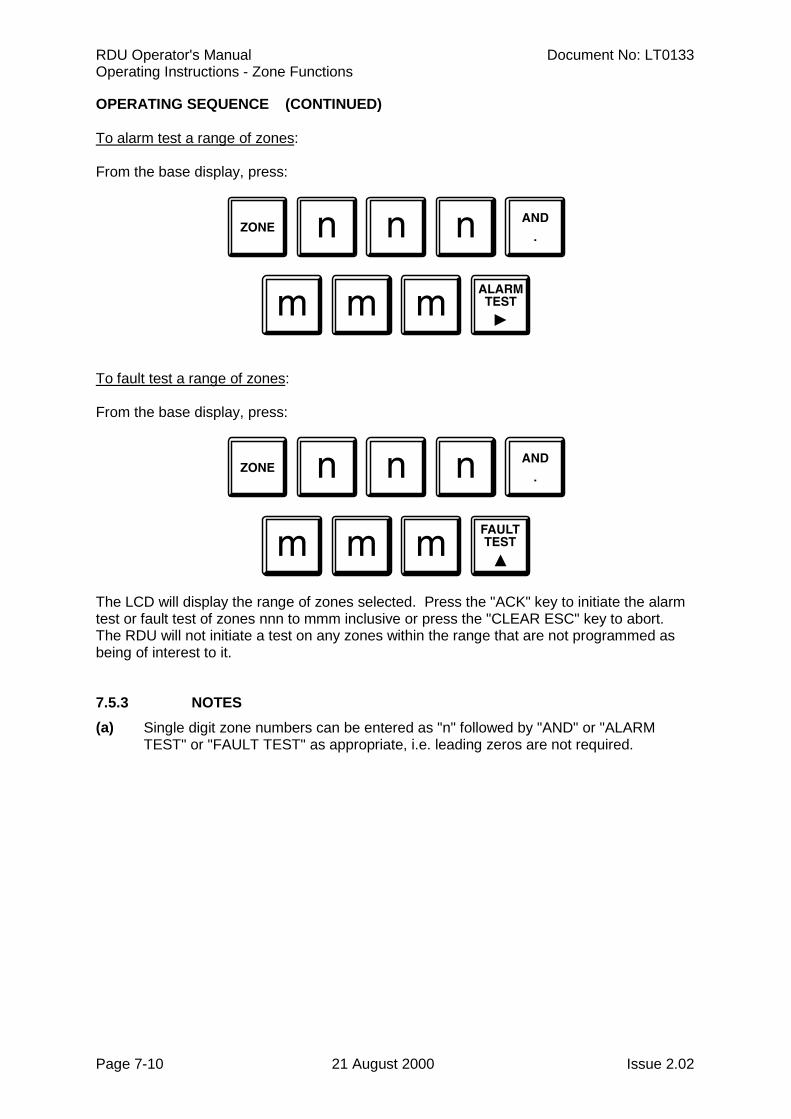
RDU Operator's Manual Document No: LT0133Operating Instructions - Zone Functions
Page 7-10 21 August 2000 Issue 2.02
OPERATING SEQUENCE (CONTINUED)
To alarm test a range of zones:
From the base display, press:
To fault test a range of zones:
From the base display, press:
The LCD will display the range of zones selected. Press the "ACK" key to initiate the alarmtest or fault test of zones nnn to mmm inclusive or press the "CLEAR ESC" key to abort.The RDU will not initiate a test on any zones within the range that are not programmed asbeing of interest to it.
7.5.3 NOTES(a) Single digit zone numbers can be entered as "n" followed by "AND" or "ALARM
TEST" or "FAULT TEST" as appropriate, i.e. leading zeros are not required.
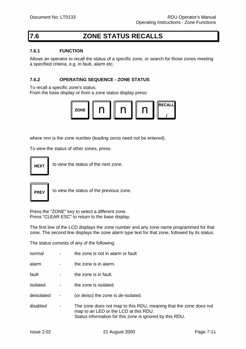
Document No: LT0133 RDU Operator's ManualOperating Instructions - Zone Functions
Issue 2.02 21 August 2000 Page 7-11
7.6 ZONE STATUS RECALLS
7.6.1 FUNCTIONAllows an operator to recall the status of a specific zone, or search for those zones meetinga specified criteria, e.g. in fault, alarm etc.
7.6.2 OPERATING SEQUENCE - ZONE STATUSTo recall a specific zone's status.From the base display or from a zone status display press:
where nnn is the zone number (leading zeros need not be entered).
To view the status of other zones, press:
to view the status of the next zone.
to view the status of the previous zone.
Press the "ZONE" key to select a different zone.Press "CLEAR ESC" to return to the base display.
The first line of the LCD displays the zone number and any zone name programmed for thatzone. The second line displays the zone alarm type text for that zone, followed by its status.
The status consists of any of the following:
normal - the zone is not in alarm or fault
alarm - the zone is in alarm.
fault - the zone is in fault.
isolated - the zone is isolated.
deisolated - (or deiso) the zone is de-isolated.
disabled - The zone does not map to this RDU, meaning that the zone does notmap to an LED or the LCD at this RDU.Status information for this zone is ignored by this RDU.
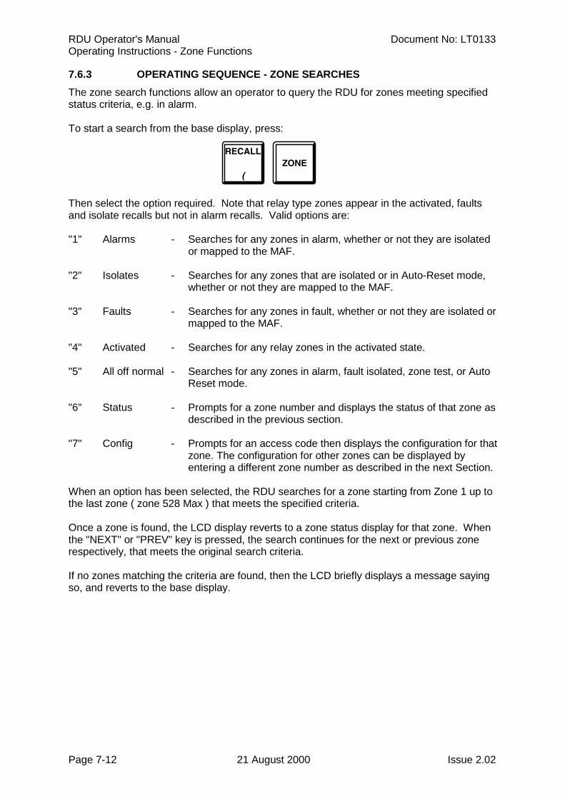
RDU Operator's Manual Document No: LT0133Operating Instructions - Zone Functions
Page 7-12 21 August 2000 Issue 2.02
7.6.3 OPERATING SEQUENCE - ZONE SEARCHESThe zone search functions allow an operator to query the RDU for zones meeting specifiedstatus criteria, e.g. in alarm.
To start a search from the base display, press:
Then select the option required. Note that relay type zones appear in the activated, faultsand isolate recalls but not in alarm recalls. Valid options are:
"1" Alarms - Searches for any zones in alarm, whether or not they are isolatedor mapped to the MAF.
"2" Isolates - Searches for any zones that are isolated or in Auto-Reset mode,whether or not they are mapped to the MAF.
"3" Faults - Searches for any zones in fault, whether or not they are isolated ormapped to the MAF.
"4" Activated - Searches for any relay zones in the activated state.
"5" All off normal - Searches for any zones in alarm, fault isolated, zone test, or Auto Reset mode.
"6" Status - Prompts for a zone number and displays the status of that zone asdescribed in the previous section.
"7" Config - Prompts for an access code then displays the configuration for thatzone. The configuration for other zones can be displayed byentering a different zone number as described in the next Section.
When an option has been selected, the RDU searches for a zone starting from Zone 1 up tothe last zone ( zone 528 Max ) that meets the specified criteria.
Once a zone is found, the LCD display reverts to a zone status display for that zone. Whenthe "NEXT" or "PREV" key is pressed, the search continues for the next or previous zonerespectively, that meets the original search criteria.
If no zones matching the criteria are found, then the LCD briefly displays a message sayingso, and reverts to the base display.
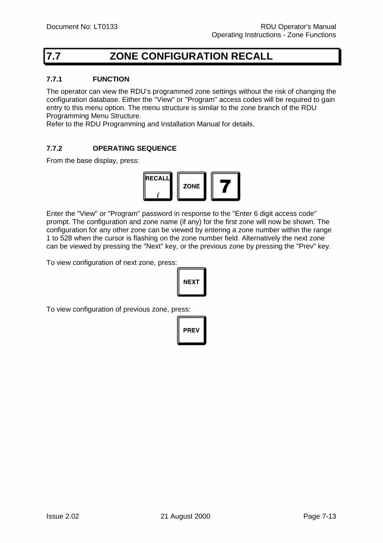
Document No: LT0133 RDU Operator's ManualOperating Instructions - Zone Functions
Issue 2.02 21 August 2000 Page 7-13
7.7 ZONE CONFIGURATION RECALL
7.7.1 FUNCTIONThe operator can view the RDU’s programmed zone settings without the risk of changing theconfiguration database. Either the "View" or "Program" access codes will be required to gainentry to this menu option. The menu structure is similar to the zone branch of the RDUProgramming Menu Structure.Refer to the RDU Programming and Installation Manual for details.
7.7.2 OPERATING SEQUENCEFrom the base display, press:
Enter the "View" or "Program" password in response to the "Enter 6 digit access code"prompt. The configuration and zone name (if any) for the first zone will now be shown. Theconfiguration for any other zone can be viewed by entering a zone number within the range1 to 528 when the cursor is flashing on the zone number field. Alternatively the next zonecan be viewed by pressing the "Next" key, or the previous zone by pressing the "Prev" key.
To view configuration of next zone, press:
To view configuration of previous zone, press:

RDU Operator's Manual Document No: LT0133Operating Instructions - Zone Functions
Page 7-14 21 August 2000 Issue 2.02
THIS PAGE INTENTIONALLY LEFT BLANK
Document No: LT0133 RDU Operator's ManualOperating Instructions - Relay/Output Functions
Issue 2.02 21 August 2000 Page 8-1
CHAPTER 8OPERATING INSTRUCTIONS
- RELAY/OUTPUT FUNCTIONS
RDU Operator's Manual Document No: LT0133Operating Instructions - Relay/Output Functions
Page 8-2 21 August 2000 Issue 2.02
8.1 INTRODUCTION
For MAF configured RDUs ( FP0558 ) the functions which can be applied to ancillary/bellrelays are : isolate/de-isolate, reset and test.
For both non-MAF RDU (FP0559) and MAF RDU (FP0558), the BELLS ISOL key or theANCILL ISOL key at the base display can be used (depending on programming) to send abells or ancillary isolate or deisolate command to the FIP. The processing of thesecommands at the FIP depends on the type and version of FIP. An F4000 FIP will processthe ancillary command as ancillary zone zero isolate or deisolate. An F3200 FIP (V2.00onwards) will process it as Plant Isolate/Deisolate.
The status of the ancillary/bell relays may be viewed on the display.The status of MAF relays (Alarm, Fault, Isolate and Standby) cannot be viewed, and MAFrelays cannot be tested directly.
8.1.1 ANCILLARY RELAYSOn an FP0558 RDU the Ancillary 1, 2 and Bell relays are controlled by a non-isolated zonealarm on any zone which is programmed (mapped) to operate that particular relay.
I.e. each zone may be programmed (mapped) to operate any ofAncillary 1, Ancillary 2 or Bell relays when a zone alarm occurs. If a zone is isolated it willnot operate any mapped relay when an alarm occurs ( also Refer to Section 6.6.1.5 of theRDU Installation and Programming Manual ).
8.1.2 ISOLATIONNon-MAF RDU (FP0559)For a non-MAF RDU, the BELLS ISOL and ANCILL ISOL keys may be used to send anisolate or deisolate command to the FIP if programmed to. The ANCILL ISOL key may beused only at the base display, but the BELLS ISOL key may be used from any display. Forboth of these keys, the command is initiated immediately without any prompting on the LCD.
MAF RDU (FP0558)The bells relay may be isolated by a bells isolate function at either the FIP or the RDU,depending on what is programmed in the RDU. A bells isolate / de-isolate command can bedone with either the "BELLS ISOL" key or with the "ISOLATE" key from the relay statusdisplay.
A specific relay can be isolated or de-isolated via the "Isolate" "Relay" or "Relay" "Isolate"keypresses. The ancillary relays can also be isolated or de-isolated via the "Isolate" keyfrom the relay status display ( refer to Section 8.6 ).
The Ancillary 1 and 2 relays may be individually isolated or de-isolated.
The Ancillary 1 relay may be programmed to follow an ancillary isolate state received fromthe FIP or it may be isolated or deisolated locally (depending on programming). Theancillary 2 relay never follows the FIP state and can only be isolated or deisolated locally atthe RDU. If programmed to, isolating or deisolating the ancillary 1 relay may also cause anancillary isolate or deisolate command to be sent to the FIP (if passon is enabled withprogramming).
Document No: LT0133 RDU Operator's ManualOperating Instructions - Relay/Output Functions
Issue 2.02 21 August 2000 Page 8-3
ISOLATION (CONTINUED)
For New Zealand operation, the building services restore (BSR) keyswitch at this RDU, atthe FIP, or another RDU (depending on programming), being activated causes the ancillary1 and 2 relays and the ancillary fire and defect outputs at the RDU to be isolated. When arelay is isolated due to an activated BSR keyswitch, the keypad commands at the RDU forisolate and deisolate do not work. Similarly with Silence Alarms and bells isolate. When theSilence Alarms keyswitch is activated the keypad cannot be used for bells isolate/deisolate.
8.2 ANCILLARY RELAY ISOLATE
8.2.1 ISOLATING/DE-ISOLATING BELLS
8.2.1.1 FUNCTIONThe RDU may control the bells isolate status at either or both the FIP and the RDU, andsimilarly the FIP may control the bells isolate status at both the FIP and the RDU dependingon what has been programmed at the RDU. The effect of pressing the "BELLS ISOL" key(or ISOLATE key) at the RDU depends on what has been programmed at the RDU.
The status of the Bells isolation is shown on the "BELLS ISOLATED" LED. If it is on steadyor flashing then either or both the FIP and RDU bells are isolated and will not sound. If theLED is OFF then the RDU bells, (if any), will sound when an un-isolated alarm is present onany zone which is programmed (mapped) to operate the bells. If the bells isolate LED isflashing at 1Hz then it indicates that both the FIP and RDU bells are isolated. If the LED ison steady then the RDU bells relay is isolated locally at the RDU. For New Zealandoperation, the Bells Isolate LED will flash at 2Hz if the Silence alarms keyswitch is operated.
De-isolating the bells allows the bells to turn on for subsequent alarms occurring, and canserve to immediately turn the bells on if any un-isolated zone alarm condition exists forzones which are mapped to the bells.
For an FP0558 (maf RDU) the bell isolate/de-isolate operation can be done from the bellsrelay status display with the ISOLATE key as well as with the BELLS ISOL key.
Australian Operation
There are four different modes, (described below), that can be programmed (with passon,follow, local parameters) which determine the bells isolate functions at the RDU.
1. RDU programmed to control the FIP bells isolate status (passon enabled).
The RDU bells isolate status follows the FIP bells isolate status - i.e. they are eitherboth isolated or both de-isolated.The bells isolate LED will flash at 1Hz if both the FIP and RDU bells (if any) areisolated and off if they are both de-isolated. Pressing the "BELLS ISOL" key once willattempt to toggle the current bells isolate status. There may be a delay of 2 to 4seconds before the bells isolate LED at the RDU shows the new status while thebells isolate command is sent to the FIP and then back to the RDU.
RDU Operator's Manual Document No: LT0133Operating Instructions - Relay/Output Functions
Page 8-4 21 August 2000 Issue 2.02
ISOLATING/DE-ISOLATING BELLS (CONTINUED)
2. RDU programmed to follow (but not control) the FIP bells isolate status andwith local control enabled.
The RDU is not able to alter the FIP bells isolate status.With "local control" enabled (FP0558 maf RDU only) then the RDU bells relay isisolated if either the FIP bells are isolated or if "locally isolated". The RDU bellsisolate LED will flash at 1 Hz if “FIP Isolated”, or otherwise be on steady if locallyisolated, or otherwise be off. Pressing the BELLS ISOL key will toggle the local bellsisolate status and will not affect the FIP bells isolate status.
3. RDU programmed to follow (but not control) the FIP bells isolate status andwith local control disabled.
With "local control" disabled then the RDU BELLS ISOL key is ignored and has noeffect on the FIP or RDU bells isolate status. The RDU bells isolate LED will flash at1Hz if "FIP isolated" and otherwise be off.
4. RDU programmed with local bells isolate control only.
The RDU does not control or follow the FIP but may locally isolate or deisolate itsbells relay. This is allowed only with an FP0558 RDU. The bells isolate LED is onsteady if the RDU bells relay is isolated and is off if the relay is de-isolated. Pressingthe BELLS ISOL key will toggle the current bells isolate status.
New Zealand Operation
Operation in NZ mode is similar to Australian mode except that the Silence Alarms keyswitchcan be used to isolate the bells. Depending on what is programmed at the RDU, the SilenceAlarms keyswitch may cause a silence alarms/bells isolate to occur at the FIP or just at theRDU, or at neither. There are three different things which can cause the bells relay at theRDU to be isolated - FIP bells isolation, local bells isolate (controlled by the BELLS ISOLkey at the RDU) and Silence Alarms keyswitch at the RDU. There are four different modes,(described below), that can be selected with programming (with passon, follow, localparameters) which determine the bells isolate and Silence Alarms keyswitch functions at theRDU.
1. RDU programmed to control the FIP bells isolate status and to send the stateof the RDU Silence Alarms keyswitch to the FIP ("passon" enabled).
The RDU bells isolate status follows the FIP bells isolate status - i.e. they are eitherboth isolated or both de-isolated. Both the BELLS ISOL key and the Silence Alarmskeyswitch at the RDU can be used to isolate / de-isolate the bells but the BELLSISOL key has no effect if the Silence Alarms keyswitch is in the activated (isolated)position.
If the Silence Alarms keyswitch is in the isolate position then both the FIP bells andthe RDU bells are isolated and the RDU bells isolate LED will flash at 2 HZ andpressing the BELLS ISOL key at either the RDU or FIP has no effect.
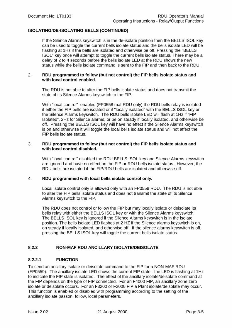
Document No: LT0133 RDU Operator's ManualOperating Instructions - Relay/Output Functions
Issue 2.02 21 August 2000 Page 8-5
ISOLATING/DE-ISOLATING BELLS (CONTINUED)
If the Silence Alarms keyswitch is in the de-isolate position then the BELLS ISOL keycan be used to toggle the current bells isolate status and the bells isolate LED will beflashing at 1Hz if the bells are isolated and otherwise be off. Pressing the "BELLSISOL" key once will attempt to toggle the current bells isolate status. There may be adelay of 2 to 4 seconds before the bells isolate LED at the RDU shows the newstatus while the bells isolate command is sent to the FIP and then back to the RDU.
2. RDU programmed to follow (but not control) the FIP bells isolate status andwith local control enabled.
The RDU is not able to alter the FIP bells isolate status and does not transmit thestate of its Silence Alarms keyswitch to the FIP.
With "local control" enabled (FP0558 maf RDU only) the RDU bells relay is isolatedif either the FIP bells are isolated or if "locally isolated" with the BELLS ISOL key orthe Silence Alarms keyswitch. The RDU bells isolate LED will flash at 1Hz if “FIPIsolated”, 2Hz for Silence alarms, or be on steady if locally isolated, and otherwise beoff. Pressing the BELLS ISOL key will have no effect if the Silence Alarms keyswitchis on and otherwise it will toggle the local bells isolate status and will not affect theFIP bells isolate status.
3. RDU programmed to follow (but not control) the FIP bells isolate status andwith local control disabled.
With "local control" disabled the RDU BELLS ISOL key and Silence Alarms keyswitchare ignored and have no effect on the FIP or RDU bells isolate status. However, theRDU bells are isolated if the FIP/RDU bells are isolated and otherwise off.
4. RDU programmed with local bells isolate control only.
Local isolate control only is allowed only with an FP0558 RDU. The RDU is not ableto alter the FIP bells isolate status and does not transmit the state of its SilenceAlarms keyswitch to the FIP.
The RDU does not control or follow the FIP but may locally isolate or deisolate itsbells relay with either the BELLS ISOL key or with the Silence Alarms keyswitch.The BELLS ISOL key is ignored if the Silence Alarms keyswitch is in the isolateposition. The bells isolate LED flashes at 2 HZ if the Silence alarms keyswitch is on,on steady if locally isolated, and otherwise off. If the silence alarms keyswitch is off,pressing the BELLS ISOL key will toggle the current bells isolate status.
8.2.2 NON-MAF RDU ANCILLARY ISOLATE/DEISOLATE
8.2.2.1 FUNCTIONTo send an ancillary isolate or deisolate command to the FIP for a NON-MAF RDU(FP0559). The ancillary isolate LED shows the current FIP state - the LED is flashing at 1Hzto indicate the FIP state is isolated. The effect of the ancillary isolate/deisolate command atthe FIP depends on the type of FIP connected. For an F4000 FIP, an ancillary zone zeroisolate or deisolate occurs. For an F3200 or F2000 FIP a Plant isolate/deisolate may occur.This function is enabled or disabled with programming according to the setting of theancillary isolate passon, follow, local parameters.
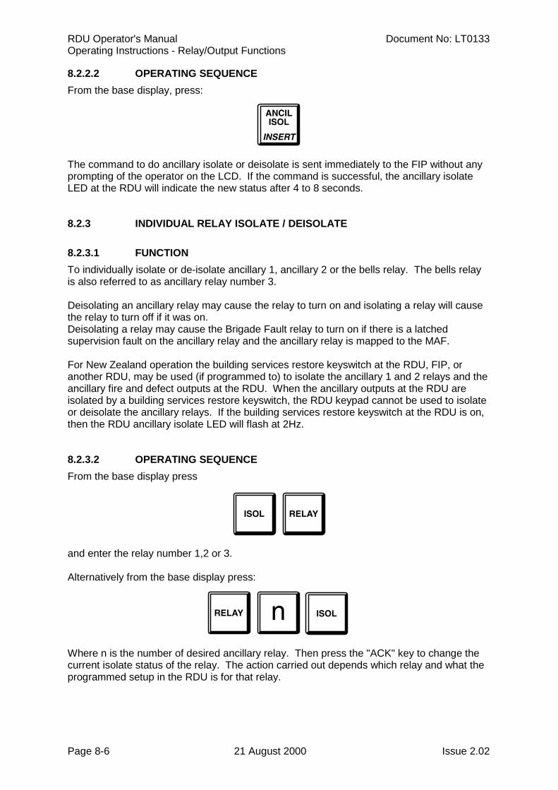
RDU Operator's Manual Document No: LT0133Operating Instructions - Relay/Output Functions
Page 8-6 21 August 2000 Issue 2.02
8.2.2.2 OPERATING SEQUENCEFrom the base display, press:
The command to do ancillary isolate or deisolate is sent immediately to the FIP without anyprompting of the operator on the LCD. If the command is successful, the ancillary isolateLED at the RDU will indicate the new status after 4 to 8 seconds.
8.2.3 INDIVIDUAL RELAY ISOLATE / DEISOLATE
8.2.3.1 FUNCTIONTo individually isolate or de-isolate ancillary 1, ancillary 2 or the bells relay. The bells relayis also referred to as ancillary relay number 3.
Deisolating an ancillary relay may cause the relay to turn on and isolating a relay will causethe relay to turn off if it was on.Deisolating a relay may cause the Brigade Fault relay to turn on if there is a latchedsupervision fault on the ancillary relay and the ancillary relay is mapped to the MAF.
For New Zealand operation the building services restore keyswitch at the RDU, FIP, oranother RDU, may be used (if programmed to) to isolate the ancillary 1 and 2 relays and theancillary fire and defect outputs at the RDU. When the ancillary outputs at the RDU areisolated by a building services restore keyswitch, the RDU keypad cannot be used to isolateor deisolate the ancillary relays. If the building services restore keyswitch at the RDU is on,then the RDU ancillary isolate LED will flash at 2Hz.
8.2.3.2 OPERATING SEQUENCEFrom the base display press
and enter the relay number 1,2 or 3.
Alternatively from the base display press:
Where n is the number of desired ancillary relay. Then press the "ACK" key to change thecurrent isolate status of the relay. The action carried out depends which relay and what theprogrammed setup in the RDU is for that relay.
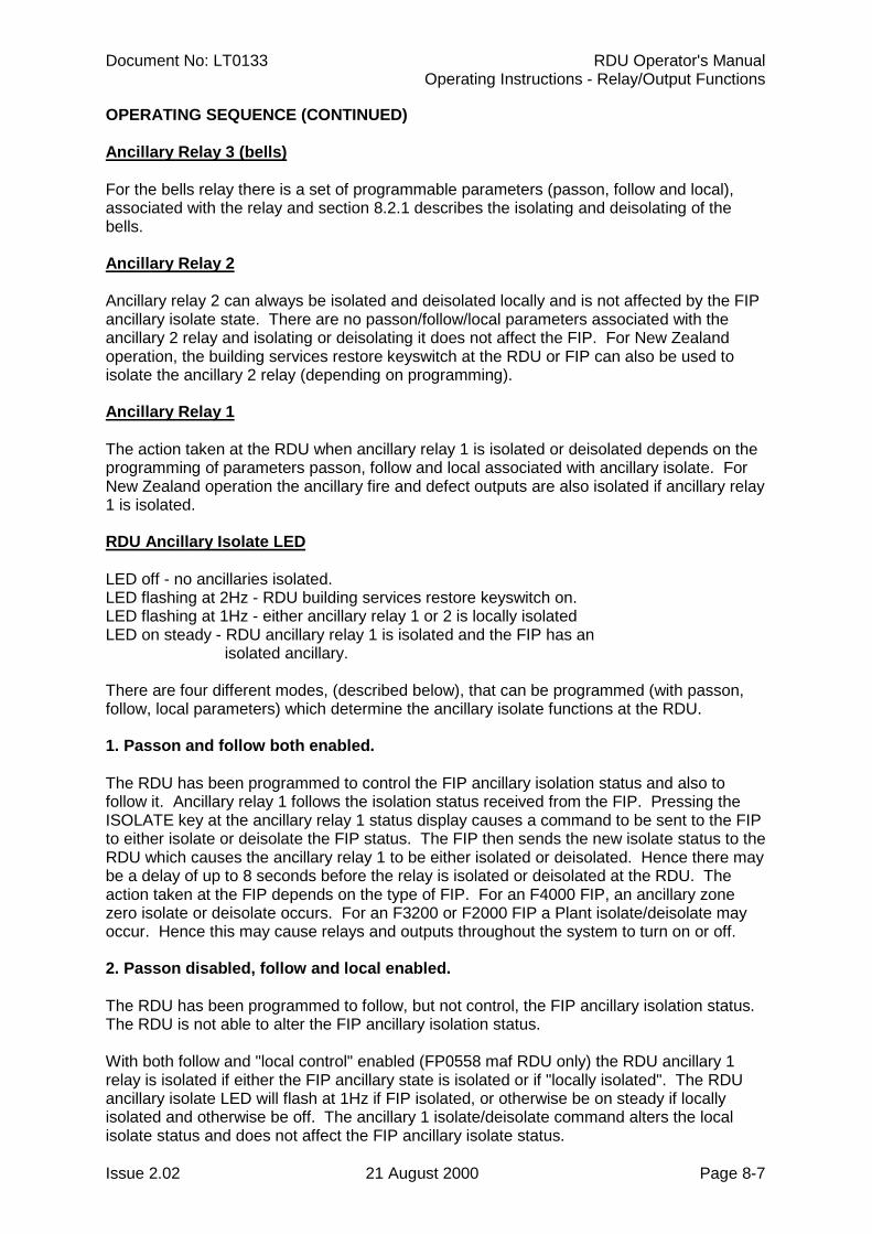
Document No: LT0133 RDU Operator's ManualOperating Instructions - Relay/Output Functions
Issue 2.02 21 August 2000 Page 8-7
OPERATING SEQUENCE (CONTINUED)
Ancillary Relay 3 (bells)
For the bells relay there is a set of programmable parameters (passon, follow and local),associated with the relay and section 8.2.1 describes the isolating and deisolating of thebells.
Ancillary Relay 2
Ancillary relay 2 can always be isolated and deisolated locally and is not affected by the FIPancillary isolate state. There are no passon/follow/local parameters associated with theancillary 2 relay and isolating or deisolating it does not affect the FIP. For New Zealandoperation, the building services restore keyswitch at the RDU or FIP can also be used toisolate the ancillary 2 relay (depending on programming).
Ancillary Relay 1
The action taken at the RDU when ancillary relay 1 is isolated or deisolated depends on theprogramming of parameters passon, follow and local associated with ancillary isolate. ForNew Zealand operation the ancillary fire and defect outputs are also isolated if ancillary relay1 is isolated.
RDU Ancillary Isolate LED
LED off - no ancillaries isolated.LED flashing at 2Hz - RDU building services restore keyswitch on.LED flashing at 1Hz - either ancillary relay 1 or 2 is locally isolatedLED on steady - RDU ancillary relay 1 is isolated and the FIP has an
isolated ancillary.
There are four different modes, (described below), that can be programmed (with passon,follow, local parameters) which determine the ancillary isolate functions at the RDU.
1. Passon and follow both enabled.
The RDU has been programmed to control the FIP ancillary isolation status and also tofollow it. Ancillary relay 1 follows the isolation status received from the FIP. Pressing theISOLATE key at the ancillary relay 1 status display causes a command to be sent to the FIPto either isolate or deisolate the FIP status. The FIP then sends the new isolate status to theRDU which causes the ancillary relay 1 to be either isolated or deisolated. Hence there maybe a delay of up to 8 seconds before the relay is isolated or deisolated at the RDU. Theaction taken at the FIP depends on the type of FIP. For an F4000 FIP, an ancillary zonezero isolate or deisolate occurs. For an F3200 or F2000 FIP a Plant isolate/deisolate mayoccur. Hence this may cause relays and outputs throughout the system to turn on or off.
2. Passon disabled, follow and local enabled.
The RDU has been programmed to follow, but not control, the FIP ancillary isolation status.The RDU is not able to alter the FIP ancillary isolation status.
With both follow and "local control" enabled (FP0558 maf RDU only) the RDU ancillary 1relay is isolated if either the FIP ancillary state is isolated or if "locally isolated". The RDUancillary isolate LED will flash at 1Hz if FIP isolated, or otherwise be on steady if locallyisolated and otherwise be off. The ancillary 1 isolate/deisolate command alters the localisolate status and does not affect the FIP ancillary isolate status.
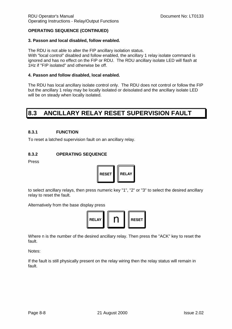
RDU Operator's Manual Document No: LT0133Operating Instructions - Relay/Output Functions
Page 8-8 21 August 2000 Issue 2.02
OPERATING SEQUENCE (CONTINUED)
3. Passon and local disabled, follow enabled.
The RDU is not able to alter the FIP ancillary isolation status.With "local control" disabled and follow enabled, the ancillary 1 relay isolate command isignored and has no effect on the FIP or RDU. The RDU ancillary isolate LED will flash at1Hz if "FIP isolated" and otherwise be off.
4. Passon and follow disabled, local enabled.
The RDU has local ancillary isolate control only. The RDU does not control or follow the FIPbut the ancillary 1 relay may be locally isolated or deisolated and the ancillary isolate LEDwill be on steady when locally isolated.
8.3 ANCILLARY RELAY RESET SUPERVISION FAULT
8.3.1 FUNCTIONTo reset a latched supervision fault on an ancillary relay.
8.3.2 OPERATING SEQUENCEPress
to select ancillary relays, then press numeric key "1", "2" or "3" to select the desired ancillaryrelay to reset the fault.
Alternatively from the base display press
Where n is the number of the desired ancillary relay. Then press the "ACK" key to reset thefault.
Notes:
If the fault is still physically present on the relay wiring then the relay status will remain infault.
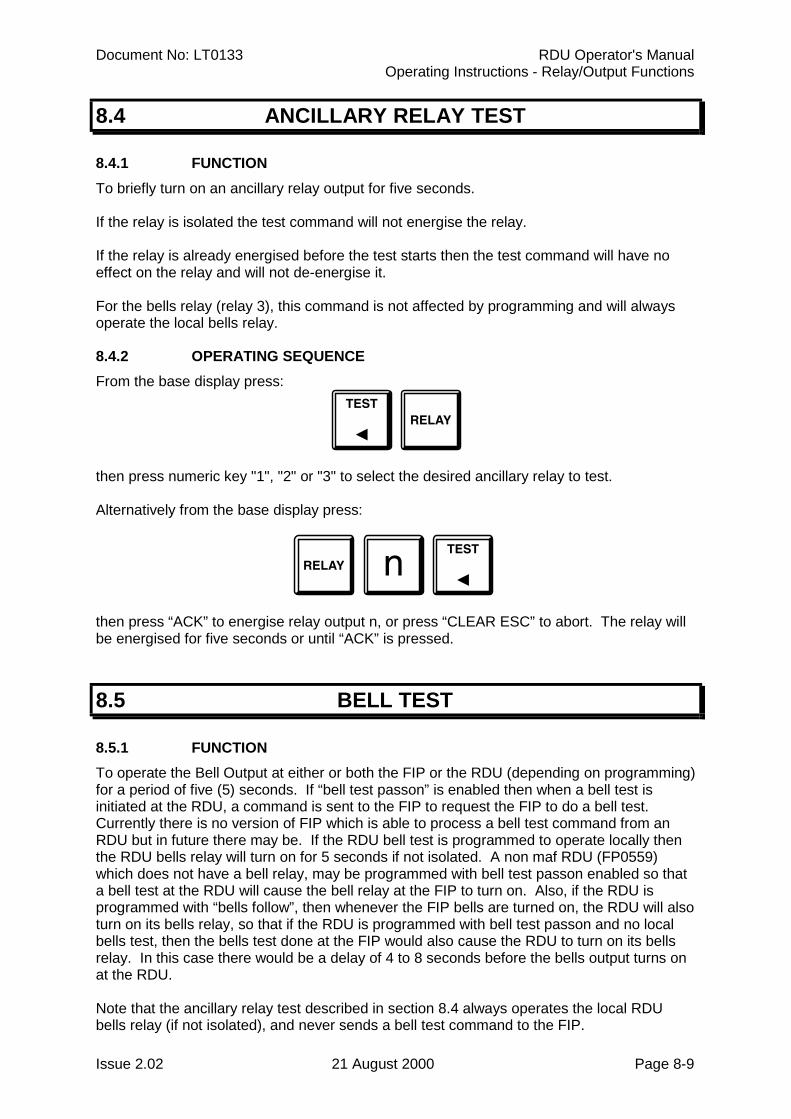
Document No: LT0133 RDU Operator's ManualOperating Instructions - Relay/Output Functions
Issue 2.02 21 August 2000 Page 8-9
8.4 ANCILLARY RELAY TEST
8.4.1 FUNCTIONTo briefly turn on an ancillary relay output for five seconds.
If the relay is isolated the test command will not energise the relay.
If the relay is already energised before the test starts then the test command will have noeffect on the relay and will not de-energise it.
For the bells relay (relay 3), this command is not affected by programming and will alwaysoperate the local bells relay.
8.4.2 OPERATING SEQUENCEFrom the base display press:
then press numeric key "1", "2" or "3" to select the desired ancillary relay to test.
Alternatively from the base display press:
then press “ACK” to energise relay output n, or press “CLEAR ESC” to abort. The relay willbe energised for five seconds or until “ACK” is pressed.
8.5 BELL TEST
8.5.1 FUNCTIONTo operate the Bell Output at either or both the FIP or the RDU (depending on programming)for a period of five (5) seconds. If “bell test passon” is enabled then when a bell test isinitiated at the RDU, a command is sent to the FIP to request the FIP to do a bell test.Currently there is no version of FIP which is able to process a bell test command from anRDU but in future there may be. If the RDU bell test is programmed to operate locally thenthe RDU bells relay will turn on for 5 seconds if not isolated. A non maf RDU (FP0559)which does not have a bell relay, may be programmed with bell test passon enabled so thata bell test at the RDU will cause the bell relay at the FIP to turn on. Also, if the RDU isprogrammed with “bells follow”, then whenever the FIP bells are turned on, the RDU will alsoturn on its bells relay, so that if the RDU is programmed with bell test passon and no localbells test, then the bells test done at the FIP would also cause the RDU to turn on its bellsrelay. In this case there would be a delay of 4 to 8 seconds before the bells output turns onat the RDU.
Note that the ancillary relay test described in section 8.4 always operates the local RDUbells relay (if not isolated), and never sends a bell test command to the FIP.
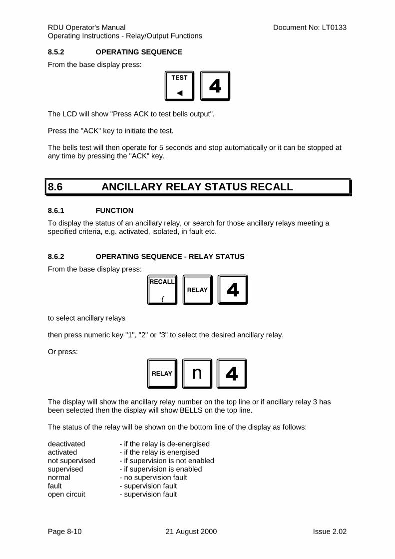
RDU Operator's Manual Document No: LT0133Operating Instructions - Relay/Output Functions
Page 8-10 21 August 2000 Issue 2.02
8.5.2 OPERATING SEQUENCEFrom the base display press:
The LCD will show "Press ACK to test bells output".
Press the "ACK" key to initiate the test.
The bells test will then operate for 5 seconds and stop automatically or it can be stopped atany time by pressing the "ACK" key.
8.6 ANCILLARY RELAY STATUS RECALL
8.6.1 FUNCTIONTo display the status of an ancillary relay, or search for those ancillary relays meeting aspecified criteria, e.g. activated, isolated, in fault etc.
8.6.2 OPERATING SEQUENCE - RELAY STATUSFrom the base display press:
to select ancillary relays
then press numeric key "1", "2" or "3" to select the desired ancillary relay.
Or press:
The display will show the ancillary relay number on the top line or if ancillary relay 3 hasbeen selected then the display will show BELLS on the top line.
The status of the relay will be shown on the bottom line of the display as follows:
deactivated - if the relay is de-energisedactivated - if the relay is energisednot supervised - if supervision is not enabledsupervised - if supervision is enablednormal - no supervision faultfault - supervision faultopen circuit - supervision fault
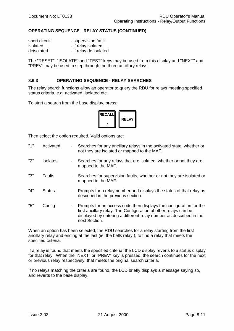
Document No: LT0133 RDU Operator's ManualOperating Instructions - Relay/Output Functions
Issue 2.02 21 August 2000 Page 8-11
OPERATING SEQUENCE - RELAY STATUS (CONTINUED)
short circuit - supervision faultisolated - if relay isolateddeisolated - if relay de-isolated
The "RESET", "ISOLATE" and "TEST" keys may be used from this display and "NEXT" and"PREV" may be used to step through the three ancillary relays.
8.6.3 OPERATING SEQUENCE - RELAY SEARCHESThe relay search functions allow an operator to query the RDU for relays meeting specifiedstatus criteria, e.g. activated, isolated etc.
To start a search from the base display, press:
Then select the option required. Valid options are:
"1" Activated - Searches for any ancillary relays in the activated state, whether ornot they are isolated or mapped to the MAF.
"2" Isolates - Searches for any relays that are isolated, whether or not they aremapped to the MAF.
"3" Faults - Searches for supervision faults, whether or not they are isolated ormapped to the MAF.
"4" Status - Prompts for a relay number and displays the status of that relay asdescribed in the previous section.
"5" Config - Prompts for an access code then displays the configuration for thefirst ancillary relay. The Configuration of other relays can bedisplayed by entering a different relay number as described in thenext Section.
When an option has been selected, the RDU searches for a relay starting from the firstancillary relay and ending at the last (ie. the bells relay ), to find a relay that meets thespecified criteria.
If a relay is found that meets the specified criteria, the LCD display reverts to a status displayfor that relay. When the "NEXT" or "PREV" key is pressed, the search continues for the nextor previous relay respectively, that meets the original search criteria.
If no relays matching the criteria are found, the LCD briefly displays a message saying so,and reverts to the base display.
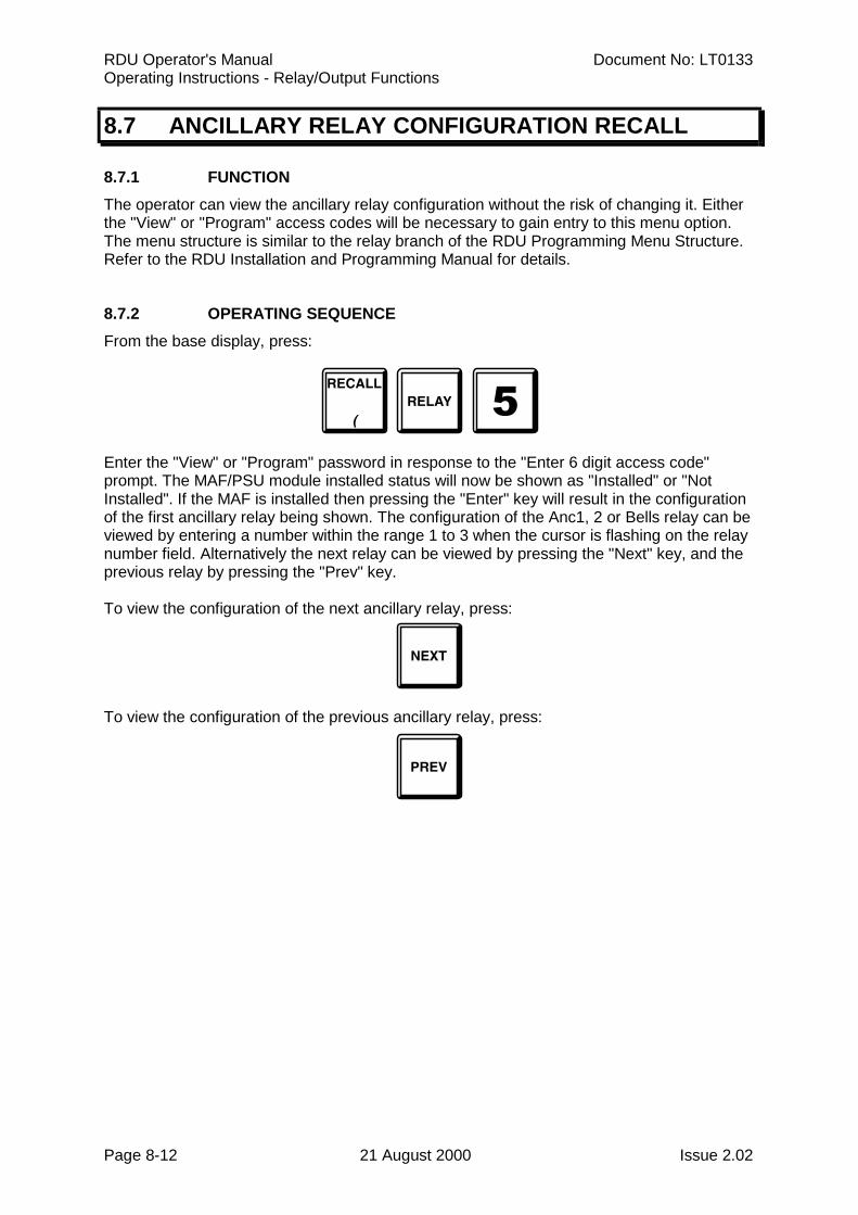
RDU Operator's Manual Document No: LT0133Operating Instructions - Relay/Output Functions
Page 8-12 21 August 2000 Issue 2.02
8.7 ANCILLARY RELAY CONFIGURATION RECALL
8.7.1 FUNCTIONThe operator can view the ancillary relay configuration without the risk of changing it. Eitherthe "View" or "Program" access codes will be necessary to gain entry to this menu option.The menu structure is similar to the relay branch of the RDU Programming Menu Structure.Refer to the RDU Installation and Programming Manual for details.
8.7.2 OPERATING SEQUENCEFrom the base display, press:
Enter the "View" or "Program" password in response to the "Enter 6 digit access code"prompt. The MAF/PSU module installed status will now be shown as "Installed" or "NotInstalled". If the MAF is installed then pressing the "Enter" key will result in the configurationof the first ancillary relay being shown. The configuration of the Anc1, 2 or Bells relay can beviewed by entering a number within the range 1 to 3 when the cursor is flashing on the relaynumber field. Alternatively the next relay can be viewed by pressing the "Next" key, and theprevious relay by pressing the "Prev" key.
To view the configuration of the next ancillary relay, press:
To view the configuration of the previous ancillary relay, press:
Document No: LT0133 RDU Operator's ManualOperating Instructions - Relay/Output Functions
Issue 2.02 21 August 2000 Page 8-13
8.8 NEW ZEALAND MODE TRIAL EVAC OPERATION
The NZ display extender board can have a trial evac keyswitch connected which can beused to energise the bells relay at either the FIP or the RDU depending on what isprogrammed at the RDU.
If the RDU is programmed to have trial evac sent to the FIP (passon enabled) then activatingthe trial evac keyswitch at the RDU will cause the bells relay at the FIP to be energised andmay also cause the bells relay (if any) at the RDU to be energised depending on the typeand version of FIP.
If the RDU is programmed to have trial evac take effect locally then activating the trial evackeyswitch at the RDU will cause the bells relay at the RDU to be energised.
A bells test may be initiated from the keypad which will also cause the bells relay to beenergised if not isolated.

RDU Operator's Manual Document No: LT0133Operating Instructions - Relay/Output Functions
Page 8-14 21 August 2000 Issue 2.02
THIS PAGE INTENTIONALLY LEFT BLANK
Document No: LT0133 RDU Operator's ManualOperating Instructions - Test Functions
Issue 2.02 21 August 2000 Page 9-1
CHAPTER 9OPERATING INSTRUCTIONS
- TEST FUNCTIONS
RDU Operator's Manual Document No: LT0133Operating Instructions - Test Functions
Page 9-2 21 August 2000 Issue 2.02
9.1 SYSTEM TEST
9.1.1 FUNCTIONThe System Test checks the integrity of the system hardware and software. It tests the RAMand EPROM, and checks the database EEPROM.
9.1.2 OPERATING SEQUENCEFrom the base display, press:
OR
A system test cannot be initiated if any of the following are present:
(a) Database EEPROM checksum error.(b) Battery very low.(c) Shift register bus fault.(d) Remote-test currently in progress.
If none of the above are present, a system test will be initiated and the LCD will show"System test in progress - press RESET to abort".
The test may be terminated prematurely by pressing the "RESET" key.
If the test fails for any reason, a test fail cadence will sound on the buzzer and an errormessage will appear on the display.
9.1.2.1 MEMORY TESTSA test of the Controller RAM, EPROM and EEPROM checksum is done. If the RAM orEPROM test fails, then the Brigade standby relay will de-energise and the "SYSTEMFAULT" LED will turn on but processing of zone alarms and faults will continue.
If the database EEPROM checksum test fails then all zone alarm and fault processing willstop and the RDU will become inoperational and the standby relay will de-energise.
To recover, do the following.
First, power the panel off and on again. This will check the database EEPROM and startprocessing if the checksum is correct. If the fault does not clear then enter program modeusing the "SET" key and entering the password. Then exit program mode which willcalculate and save the checksum of the database and then re-check the checksum.
It is advisable to do a printout of the entire database and re-check all of the programmeddata. Alternatively, upload a new database into the RDU by entering program mode andloading a previously saved database.
Document No: LT0133 RDU Operator's ManualOperating Instructions - Test Functions
Issue 2.02 21 August 2000 Page 9-3
9.2 LCD/LAMP (LED) TEST
9.2.1 FUNCTIONTo momentarily flash all LED indicators to visually inspect that they are working correctly,and to test operation of the LCD.
9.2.2 OPERATING SEQUENCEFrom the base display, press:
A number of different test patterns are displayed on the LCD.
At the same time as the LCD test pattern is shown, the LED indicators on the front panel willbe flashed on for half a second, off for half a second, for 5 seconds. The "MAINS ON" LEDis not affected by the test. The other front panel LEDs should be on and off simultaneouslyfor the 5 seconds.
After the front panel LEDs and LCD have been tested, the zone (and relay) LED Displayboards will be tested, one board (16 zones) at a time. Each Display board will be tested forabout 2 seconds and all 48 LEDs on the board will be turned on for 1.5 seconds and then offfor half a second.
The testing of the LED display boards can be terminated by pressing "RESET".
The test can be paused or resumed at a particular display board by using the "ISOL" key.The test can be stepped to the next Display board by using the "ACK" key. The "ACK" keycan be used to step to the next display board when the test is in pause mode.
9.3 BUZZER TEST
9.3.1 FUNCTIONTo test the buzzer for both loud and quiet operation. (The buzzer has loud operation forwhen the RDU door is closed, and quiet for when the door is open).
9.3.2 OPERATING SEQUENCEFrom the base display, press:
The buzzer will turn on "loud" for 2-3 seconds, followed by "quiet" for 2-3 seconds.
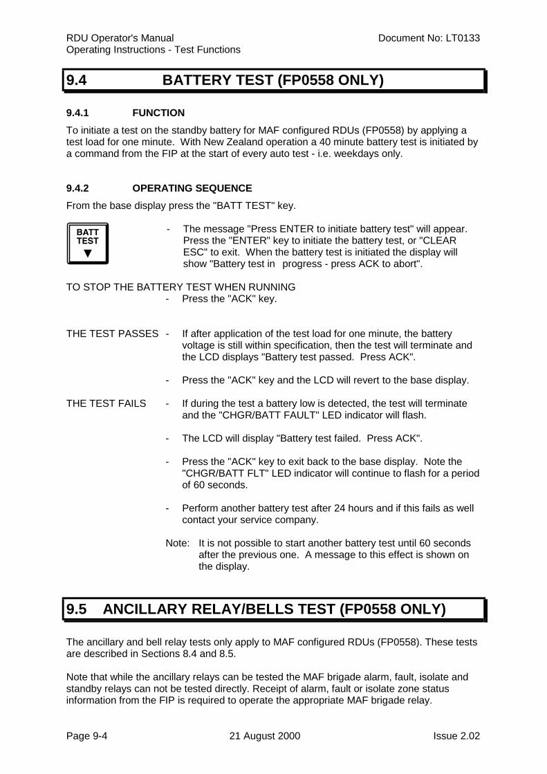
RDU Operator's Manual Document No: LT0133Operating Instructions - Test Functions
Page 9-4 21 August 2000 Issue 2.02
9.4 BATTERY TEST (FP0558 ONLY)
9.4.1 FUNCTIONTo initiate a test on the standby battery for MAF configured RDUs (FP0558) by applying atest load for one minute. With New Zealand operation a 40 minute battery test is initiated bya command from the FIP at the start of every auto test - i.e. weekdays only.
9.4.2 OPERATING SEQUENCEFrom the base display press the "BATT TEST" key.
- The message "Press ENTER to initiate battery test" will appear.Press the "ENTER" key to initiate the battery test, or "CLEARESC" to exit. When the battery test is initiated the display will show "Battery test in progress - press ACK to abort".
TO STOP THE BATTERY TEST WHEN RUNNING- Press the "ACK" key.
THE TEST PASSES - If after application of the test load for one minute, the batteryvoltage is still within specification, then the test will terminate andthe LCD displays "Battery test passed. Press ACK".
- Press the "ACK" key and the LCD will revert to the base display.
THE TEST FAILS - If during the test a battery low is detected, the test will terminateand the "CHGR/BATT FAULT" LED indicator will flash.
- The LCD will display "Battery test failed. Press ACK".
- Press the "ACK" key to exit back to the base display. Note the"CHGR/BATT FLT" LED indicator will continue to flash for a periodof 60 seconds.
- Perform another battery test after 24 hours and if this fails as wellcontact your service company.
Note: It is not possible to start another battery test until 60 secondsafter the previous one. A message to this effect is shown onthe display.
9.5 ANCILLARY RELAY/BELLS TEST (FP0558 ONLY)
The ancillary and bell relay tests only apply to MAF configured RDUs (FP0558). These testsare described in Sections 8.4 and 8.5.
Note that while the ancillary relays can be tested the MAF brigade alarm, fault, isolate andstandby relays can not be tested directly. Receipt of alarm, fault or isolate zone statusinformation from the FIP is required to operate the appropriate MAF brigade relay.
Document No: LT0133 RDU Operator's ManualPlacing Into Operation
Issue 2.02 21 August 2000 Page 10-1
CHAPTER 10PLACING INTO OPERATION
RDU Operator's Manual Document No: LT0133Placing Into Operation
Page 10-2 21 August 2000 Issue 2.02
10.1 GENERAL
This chapter describes the procedure to place an RDU into operation. It assumes that themains and other field wiring has been connected, but that the battery has not. Note that allelectronic modules were tested and adjusted in the factory and should need no furtheradjustment.
Customisation will be required by the system installer to program the RDU to set up anumber of parameters, including :
- RDU address to match that at the FIP ( default = 1 );- type of Display / Relay Driver board(s) fitted (if any );- and many other parameters.
Please refer to Chapter 6 of the "RDU Installation and Programming Manual" for moreinformation.
10.2 PLACING INTO OPERATION: FP0558
10.2.1 VISUAL INSPECTIONBefore switching on power, inspect the cabinet and internals. Check as follows:
1. Check that all equipment is securely mounted, and that all cables are connected atthe appropriate points. The factory checklist is included.
2. Check the 16 Zone LED Displays ( if present ) are fitted and connected correctly withlink LK1 fitted on the last board only. For New Zealand operation, check that thedisplay extender board (if any), is connected correctly and that none of the displayboards have link LK1 fitted.
3. Check that (if required) the additional battery test resistors, 6A power supply andovercurrent protection device are fitted. Note that batteries are not to be connectedyet. For New Zealand operation, all battery test resistors (R52, R53) must beremoved otherwise they will burn out when the 40 minute daily auto batterytest is done.
4. Check that links Lk2-4 on the MAF are fitted (unless Anc3, clean contacts is beingused).
5. Check that a 3 wire comms connection has been made to the FIP with Tx & Rx at theFIP routed to Rx & Tx respectively at the RDU. Also check that the FIP has beenprogrammed correctly to send status/ receive commands to/from the RDU.
The "MAINS ISOLATE SWITCH" is located at the top right hand side of the cabinet rear, tothe left of the mains transformer, behind the inner display door. This controls the mainspower to the RDU, charger and power supply, and should be left on once the RDU isoperational.
NOTE: The Battery is not disconnected by the "MAINS ISOLATE SWITCH".
Document No: LT0133 RDU Operator's ManualPlacing Into Operation
Issue 2.02 21 August 2000 Page 10-3
10.2.2 POWER UPNOTE: The Battery is not disconnected by the "MAINS ISOLATE SWITCH".
To place the RDU into operation, perform the following steps:
STEP 1 Ensure that the Mains Isolate Switch is OFF.
STEP 2 Ensure that 240 VAC is connected to the panel from the mains distributionswitchboard.
STEP 3 If an E2INIT is required before programming, fit Lk7 on the Controller to theDATABASE WRITE ENABLE position and fit minijump SW1. (Refer to theRDU Programming and Installation Manual).
Turn the Mains Isolate Switch ON.
STEP 4 Check that the buzzer sounds and all LEDs on the Operator Display panelflash for 2 seconds (except Mains On).
STEP 5 Check that the green "MAINS ON" LED indicator is on.The Controller performs tests on its memory, electronics, and the LCD.
STEP 6 If doing an E2INIT, remove minijump SW1 and press "ACK" to complete thesequence.
STEP 7 Check that the LCD has good visibility. The LCD displays the RDU pcbconfiguration before showing the Base Display.
STEP 8 Install and connect the batteries.Take care not to short the battery leads or connect in reverse polarity whenconnecting.
STEP 9 If required, complete programming as per the RDU Programming andInstallation Manual and then fit Lk7 on the Controller to the DATABASEPROTECT position. Use the Recall CRC command from the Recall menu(refer section 6.8) and record the database CRC and last changed time/datein the logbook.
STEP 10 Perform a Battery Test. If this fails check the battery connections, leave for24 hours and then retest.
STEP 11 Perform a Bells and System Test at the RDU, then a system test at the FIP(de-isolate all zones first).
STEP 12 Check that zone status conditions at the FIP are received and annunciatedcorrectly at the RDU and that commands issued at the RDU ( non-mimicmode ) act correctly to acknowledge, reset and isolate zones. A fullcommissioning test should be carried out as per AS1670 or NZS4512.
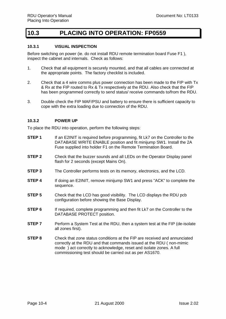
RDU Operator's Manual Document No: LT0133Placing Into Operation
Page 10-4 21 August 2000 Issue 2.02
10.3 PLACING INTO OPERATION: FP0559
10.3.1 VISUAL INSPECTIONBefore switching on power (ie. do not install RDU remote termination board Fuse F1 ),inspect the cabinet and internals. Check as follows:
1. Check that all equipment is securely mounted, and that all cables are connected atthe appropriate points. The factory checklist is included.
2. Check that a 4 wire comms plus power connection has been made to the FIP with Tx& Rx at the FIP routed to Rx & Tx respectively at the RDU. Also check that the FIPhas been programmed correctly to send status/ receive commands to/from the RDU.
3. Double check the FIP MAF/PSU and battery to ensure there is sufficient capacity tocope with the extra loading due to connection of the RDU.
10.3.2 POWER UPTo place the RDU into operation, perform the following steps:
STEP 1 If an E2INIT is required before programming, fit Lk7 on the Controller to theDATABASE WRITE ENABLE position and fit minijump SW1. Install the 2AFuse supplied into holder F1 on the Remote Termination Board.
STEP 2 Check that the buzzer sounds and all LEDs on the Operator Display panelflash for 2 seconds (except Mains On).
STEP 3 The Controller performs tests on its memory, electronics, and the LCD.
STEP 4 If doing an E2INIT, remove minijump SW1 and press "ACK" to complete thesequence.
STEP 5 Check that the LCD has good visibility. The LCD displays the RDU pcbconfiguration before showing the Base Display.
STEP 6 If required, complete programming and then fit Lk7 on the Controller to theDATABASE PROTECT position.
STEP 7 Perform a System Test at the RDU, then a system test at the FIP (de-isolateall zones first).
STEP 8 Check that zone status conditions at the FIP are received and annunciatedcorrectly at the RDU and that commands issued at the RDU ( non-mimicmode ) act correctly to acknowledge, reset and isolate zones. A fullcommissioning test should be carried out as per AS1670.
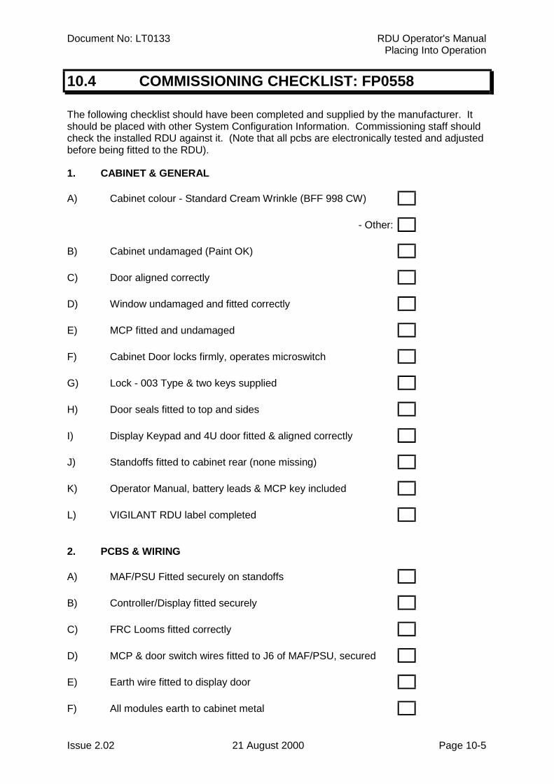
Document No: LT0133 RDU Operator's ManualPlacing Into Operation
Issue 2.02 21 August 2000 Page 10-5
10.4 COMMISSIONING CHECKLIST: FP0558
The following checklist should have been completed and supplied by the manufacturer. Itshould be placed with other System Configuration Information. Commissioning staff shouldcheck the installed RDU against it. (Note that all pcbs are electronically tested and adjustedbefore being fitted to the RDU).
1. CABINET & GENERAL
A) Cabinet colour - Standard Cream Wrinkle (BFF 998 CW)
- Other:
B) Cabinet undamaged (Paint OK)
C) Door aligned correctly
D) Window undamaged and fitted correctly
E) MCP fitted and undamaged
F) Cabinet Door locks firmly, operates microswitch
G) Lock - 003 Type & two keys supplied
H) Door seals fitted to top and sides
I) Display Keypad and 4U door fitted & aligned correctly
J) Standoffs fitted to cabinet rear (none missing)
K) Operator Manual, battery leads & MCP key included
L) VIGILANT RDU label completed
2. PCBS & WIRING
A) MAF/PSU Fitted securely on standoffs
B) Controller/Display fitted securely
C) FRC Looms fitted correctly
D) MCP & door switch wires fitted to J6 of MAF/PSU, secured
E) Earth wire fitted to display door
F) All modules earth to cabinet metal
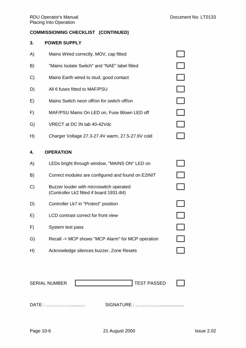
RDU Operator's Manual Document No: LT0133Placing Into Operation
Page 10-6 21 August 2000 Issue 2.02
COMMISSIONING CHECKLIST (CONTINUED)
3. POWER SUPPLY
A) Mains Wired correctly, MOV, cap fitted
B) "Mains Isolate Switch" and "NAE" label fitted
C) Mains Earth wired to stud, good contact
D) All 6 fuses fitted to MAF/PSU
E) Mains Switch neon off/on for switch off/on
F) MAF/PSU Mains On LED on, Fuse Blown LED off
G) VRECT at DC IN tab 40-42Vdc
H) Charger Voltage 27.3-27.4V warm, 27.5-27.6V cold
4. OPERATION
A) LEDs bright through window, "MAINS ON" LED on
B) Correct modules are configured and found on E2INIT
C) Buzzer louder with microswitch operated(Controller Lk2 fitted if board 1931-84)
D) Controller Lk7 in "Protect" position
E) LCD contrast correct for front view
F) System test pass
G) Recall -> MCP shows "MCP Alarm" for MCP operation
H) Acknowledge silences buzzer, Zone Resets
SERIAL NUMBER TEST PASSED
DATE : ……………............. SIGNATURE : ……….….......................
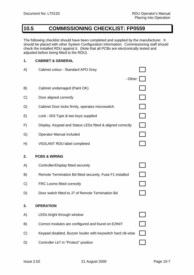
Document No: LT0133 RDU Operator's ManualPlacing Into Operation
Issue 2.02 21 August 2000 Page 10-7
10.5 COMMISSIONING CHECKLIST: FP0559
The following checklist should have been completed and supplied by the manufacturer. Itshould be placed with other System Configuration Information. Commissioning staff shouldcheck the installed RDU against it. (Note that all PCBs are electronically tested andadjusted before being fitted to the RDU).
1. CABINET & GENERAL
A) Cabinet colour - Standard APO Grey
- Other:
B) Cabinet undamaged (Paint OK)
C) Door aligned correctly
D) Cabinet Door locks firmly, operates microswitch
E) Lock - 003 Type & two keys supplied
F) Display, Keypad and Status LEDs fitted & aligned correctly
G) Operator Manual included
H) VIGILANT RDU label completed
2. PCBS & WIRING
A) Controller/Display fitted securely
B) Remote Termination Bd fitted securely, Fuse F1 installed
C) FRC Looms fitted correctly
D) Door switch fitted to J7 of Remote Termination Bd
3. OPERATION
A) LEDs bright through window
B) Correct modules are configured and found on E2INIT
C) Keypad disabled, Buzzer louder with keyswitch hard clk-wise
D) Controller Lk7 in "Protect" position
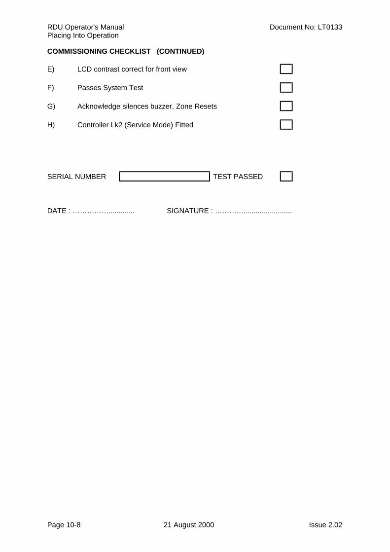
RDU Operator's Manual Document No: LT0133Placing Into Operation
Page 10-8 21 August 2000 Issue 2.02
COMMISSIONING CHECKLIST (CONTINUED)
E) LCD contrast correct for front view
F) Passes System Test
G) Acknowledge silences buzzer, Zone Resets
H) Controller Lk2 (Service Mode) Fitted
SERIAL NUMBER TEST PASSED
DATE : ……………............. SIGNATURE : ……….….......................
Document No: LT0133 RDU Operator's ManualSystem Testing & Maintenance
Issue 2.02 21 August 2000 Page 11-1
CHAPTER 11SYSTEM TESTING AND MAINTENANCE
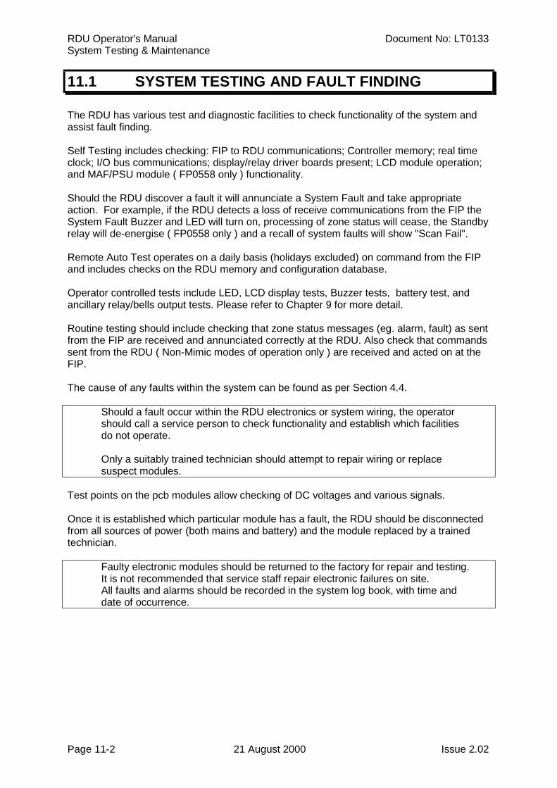
RDU Operator's Manual Document No: LT0133System Testing & Maintenance
Page 11-2 21 August 2000 Issue 2.02
11.1 SYSTEM TESTING AND FAULT FINDING
The RDU has various test and diagnostic facilities to check functionality of the system andassist fault finding.
Self Testing includes checking: FIP to RDU communications; Controller memory; real timeclock; I/O bus communications; display/relay driver boards present; LCD module operation;and MAF/PSU module ( FP0558 only ) functionality.
Should the RDU discover a fault it will annunciate a System Fault and take appropriateaction. For example, if the RDU detects a loss of receive communications from the FIP theSystem Fault Buzzer and LED will turn on, processing of zone status will cease, the Standbyrelay will de-energise ( FP0558 only ) and a recall of system faults will show "Scan Fail".
Remote Auto Test operates on a daily basis (holidays excluded) on command from the FIPand includes checks on the RDU memory and configuration database.
Operator controlled tests include LED, LCD display tests, Buzzer tests, battery test, andancillary relay/bells output tests. Please refer to Chapter 9 for more detail.
Routine testing should include checking that zone status messages (eg. alarm, fault) as sentfrom the FIP are received and annunciated correctly at the RDU. Also check that commandssent from the RDU ( Non-Mimic modes of operation only ) are received and acted on at theFIP.
The cause of any faults within the system can be found as per Section 4.4.
Should a fault occur within the RDU electronics or system wiring, the operatorshould call a service person to check functionality and establish which facilitiesdo not operate.
Only a suitably trained technician should attempt to repair wiring or replacesuspect modules.
Test points on the pcb modules allow checking of DC voltages and various signals.
Once it is established which particular module has a fault, the RDU should be disconnectedfrom all sources of power (both mains and battery) and the module replaced by a trainedtechnician.
Faulty electronic modules should be returned to the factory for repair and testing.It is not recommended that service staff repair electronic failures on site.
All faults and alarms should be recorded in the system log book, with time anddate of occurrence.
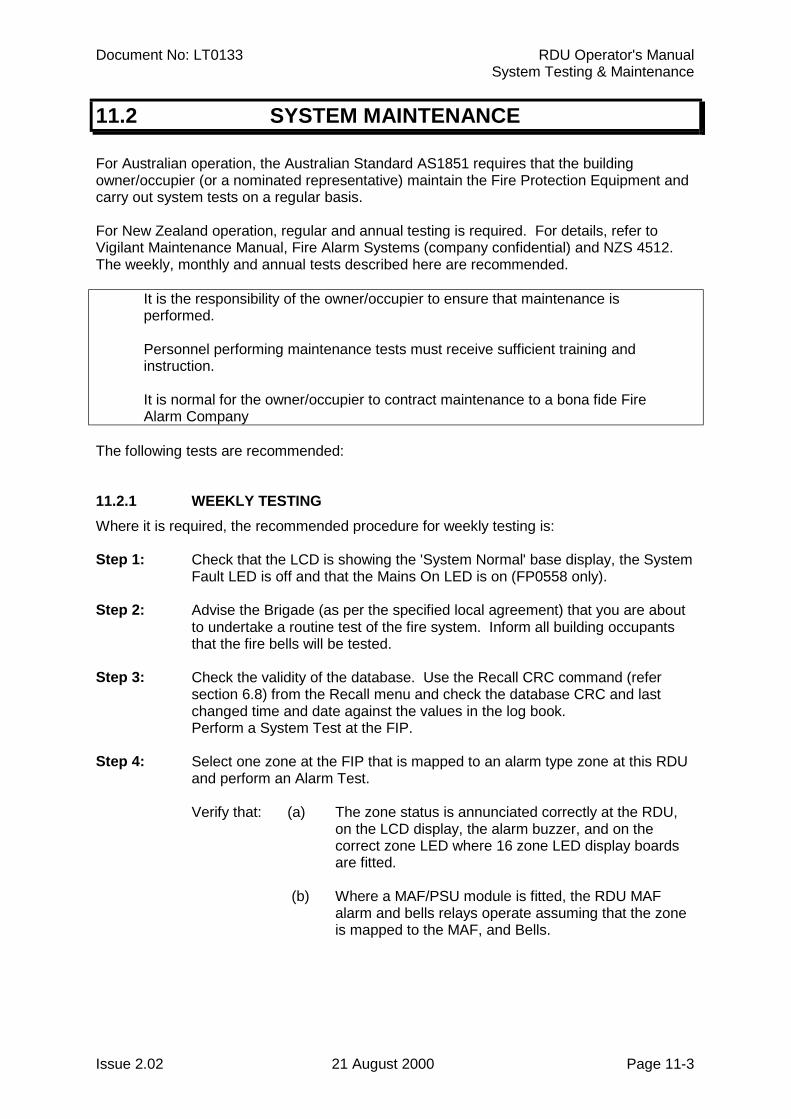
Document No: LT0133 RDU Operator's ManualSystem Testing & Maintenance
Issue 2.02 21 August 2000 Page 11-3
11.2 SYSTEM MAINTENANCE
For Australian operation, the Australian Standard AS1851 requires that the buildingowner/occupier (or a nominated representative) maintain the Fire Protection Equipment andcarry out system tests on a regular basis.
For New Zealand operation, regular and annual testing is required. For details, refer toVigilant Maintenance Manual, Fire Alarm Systems (company confidential) and NZS 4512.The weekly, monthly and annual tests described here are recommended.
It is the responsibility of the owner/occupier to ensure that maintenance isperformed.
Personnel performing maintenance tests must receive sufficient training and instruction.
It is normal for the owner/occupier to contract maintenance to a bona fide FireAlarm Company
The following tests are recommended:
11.2.1 WEEKLY TESTINGWhere it is required, the recommended procedure for weekly testing is:
Step 1: Check that the LCD is showing the 'System Normal' base display, the SystemFault LED is off and that the Mains On LED is on (FP0558 only).
Step 2: Advise the Brigade (as per the specified local agreement) that you are aboutto undertake a routine test of the fire system. Inform all building occupantsthat the fire bells will be tested.
Step 3: Check the validity of the database. Use the Recall CRC command (refersection 6.8) from the Recall menu and check the database CRC and lastchanged time and date against the values in the log book.Perform a System Test at the FIP.
Step 4: Select one zone at the FIP that is mapped to an alarm type zone at this RDUand perform an Alarm Test.
Verify that: (a) The zone status is annunciated correctly at the RDU,on the LCD display, the alarm buzzer, and on thecorrect zone LED where 16 zone LED display boardsare fitted.
(b) Where a MAF/PSU module is fitted, the RDU MAFalarm and bells relays operate assuming that the zoneis mapped to the MAF, and Bells.
RDU Operator's Manual Document No: LT0133System Testing & Maintenance
Page 11-4 21 August 2000 Issue 2.02
WEEKLY TESTING (CONTINUED)
Step 5: Acknowledge and reset the alarm at the RDU. Verify that the alarm status is cleared ( Non-Mimic operating modes only ).
Step 6: Perform a Battery Test (FP0558 only). This is not necessary for New Zealandoperation since a 40 minute battery test at the RDU is initiated with every FIPauto test.
Step 7: Check that the LCD is showing the 'System Normal' base display and that theMains On LED is on (FP0558 only).
Step 8: Record the results of these tests in the Log Book.
Step 9: Inform the Brigade and all others concerned that the test is concluded.
11.2.2 MONTHLY TESTINGIn addition to the Weekly Testing described above, perform the following monthly tests:
Step 1: Test outputs and audible alarms.
Step 2: Perform an LED and Display test.
Step 3: Visually inspect the cabinet and panel to ensure it is clean, operable andintact. Inspect the dust seal, and ensure that it is undamaged.
NOTES:
1. If there are Mimics, repeater Panels, etc connected to the RDU; these also requiretesting and inspecting.
2. The integrity of the RDU is only as good as that of the FIP from which it receivesstatus information. As such the FIP must also be adequately maintained and tested,preferably at the same time as the RDU is tested. Please refer to the FIP Operator'sManual for the relevant system test procedure.
11.2.3 ANNUAL TESTINGAustralian Standard AS1851.8 requires that all fire detection and alarm systems bethoroughly tested each year by a competent service/maintenance company.
The service/maintenance company should ensure that the performance of the procedure setout in AS1851.8 is witnessed by the owner of the RDU System installation, or the owner'sauthorised agent.
For New Zealand operation, regular and annual testing is required. For details, refer toVigilant Maintenance Manual, Fire Alarm Systems, (company confidential), and NZS 4512.