Embed Size (px)
Citation preview

Document No: 4020-M010 1st February, 1997 Issue 2.0
FIRE INDICATOR PANEL TYPE 4020
OPERATING MANUAL VERSION 2.0 FIRMWARE

Page ii 4020 OPERATORS MANUAL
Document No: 4020-M010 1st February, 1997 Issue 2.0
GLOSSARY OF STANDARD TERMS
The following abbreviations are used throughout this manual: ACF: Ancillary control facility. "Ackd": Display abbreviation for acknowledged condition. AVF: Alarm Verification Facility. ALM: Display abbreviation for alarm condition. AS1668: Australian Standard AS1668 specifying the use of mechanical ventilation
and air-conditioning in buildings. FIP: Fire Indicator Panel. "Isol": Display abbreviation for Isolated condition. LCD: Liquid Crystal Display. LED: Light Emitting Diode. MANUFACTURERS DETAILS APPROVALS: AUSTRALIAN STANDARDS AS1603.4 SSL CERTIFICATE OF COMPLIANCE NUMBER: 197
The 4020 Fire Indicator Panel is manufactured by:
Simplex International Pty Ltd ACN: 008 435 443
140 Old Pittwater Road Brookvale N.S.W. 2100 Australia
Phone: (02) 9466-2333
Notice: The contents of this document are subject to change without notice.
4020 OPERATORS MANUAL Page iii
Document No: 4020-M010 1st February, 1997 Issue 2.0
CONTENTS
Page
1 COMPATIBLE ACTUATING DEVICES ...................................................................... 1
1.1 SIMPLEX RANGE: ................................................................................................... 1 1.2 HOCHIKI RANGE:.................................................................................................... 1 1.3 OLSEN RANGE: ...................................................................................................... 1 1.4 APOLLO................................................................................................................... 2 1.5 PANELECT/PANASONIC......................................................................................... 2
2 COMPATIBLE BATTERIES........................................................................................ 3
3 SPECIFICATION ......................................................................................................... 4
3.1 GENERAL ................................................................................................................ 4 3.2 INPUTS.................................................................................................................... 4 3.3 OUTPUTS................................................................................................................ 4 3.4 INDICATORS AND DISPLAY................................................................................... 4 3.5 KEYPAD CONTROLS.............................................................................................. 5 3.6 PROGRAMMING FUNCTIONS................................................................................ 5 3.7 COMMUNICATIONS PORT (OPTIONAL) ................................................................ 5 3.8 EXPANSION CARDS............................................................................................... 5
4 AMENDMENTS TO 4020 OPERATOR MANUAL ...................................................... 6
5 INTRODUCTION ......................................................................................................... 9
5.1 OPERATOR FRONT PANEL ................................................................................. 11
6 ALARM CONDITIONS .............................................................................................. 14
6.1 ACKNOWLEDGING ALARMS................................................................................ 14 6.2 RESETTING ZONES IN ALARM............................................................................ 16 6.3 ISOLATING ZONES IN ALARM ............................................................................. 16
7 FAULT CONDITIONS ............................................................................................... 18
7.1 ACKNOWLEDGING FAULTS................................................................................. 18 7.2 BUZZER MUTE FACILITY ..................................................................................... 20
8 COMMISSIONING AND SERVICING ....................................................................... 23
8.1 KEYPAD FUNCTION KEYS................................................................................... 23 8.2 ALARM TEST......................................................................................................... 28
8.2.1 Global Alarm Test......................................................................................... 28 8.2.2 Individual Zone Alarm Test .......................................................................... 29
8.3 FAULT TEST.......................................................................................................... 31 8.4 ISOLATING / DE-ISOLATING CIRCUITS............................................................... 31 8.5 OPERATION OF NON-LATCH AS1668 ZONES.................................................... 33
8.5.1 Displaying the Status of AS1668 Zones........................................................ 33 8.6 BRIGADE TEST ..................................................................................................... 34 8.7 WALKTEST MODE ................................................................................................ 36
Page iv 4020 OPERATORS MANUAL
Document No: 4020-M010 1st February, 1997 Issue 2.0
9 PLACING INTO OPERATION................................................................................... 38
9.1 SETTING BATTERY CHARGER OUTPUT VOLTAGE:.......................................... 40 9.2 COMMISSIONING CHECKLIST............................................................................. 42
10 APPENDIX .............................................................................................................. 44
10.1 ALARM VERIFICATION ZONE PROCESSING.................................................... 44 10.2 AS1668 ZONE PROCESSING ............................................................................. 44 10.3 FAULT CONDITIONS........................................................................................... 45
11 PROGRAMMING SHEETS ..................................................................................... 46

4020 OPERATORS MANUAL Page v
Document No: 4020-M010 1st February, 1997 Issue 2.0
PANEL DETAILS panel sticker
4020 Panel supplied by
Installation location
Contract/Job Number
As installed FIP System drawing number
Panel Installation date
Panel Commissioned date
Maintenance Company
Telephone
Service Contact

4020 OPERATORS MANUAL Page 1
Document No: 4020-M010 1st February, 1997 Issue 2.0
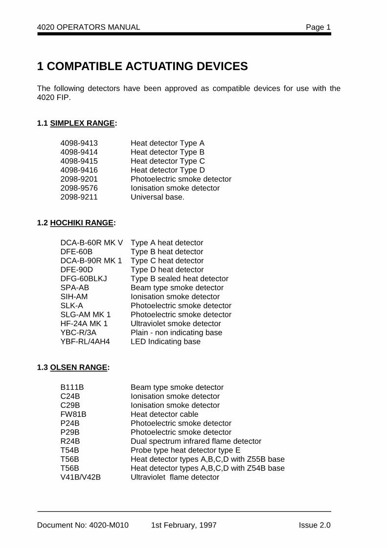
1 COMPATIBLE ACTUATING DEVICES
The following detectors have been approved as compatible devices for use with the 4020 FIP.
1.1 SIMPLEX RANGE:
4098-9413 Heat detector Type A 4098-9414 Heat detector Type B 4098-9415 Heat detector Type C 4098-9416 Heat detector Type D 2098-9201 Photoelectric smoke detector 2098-9576 Ionisation smoke detector 2098-9211 Universal base.
1.2 HOCHIKI RANGE:
DCA-B-60R MK V Type A heat detector DFE-60B Type B heat detector DCA-B-90R MK 1 Type C heat detector DFE-90D Type D heat detector DFG-60BLKJ Type B sealed heat detector SPA-AB Beam type smoke detector SIH-AM Ionisation smoke detector SLK-A Photoelectric smoke detector SLG-AM MK 1 Photoelectric smoke detector HF-24A MK 1 Ultraviolet smoke detector YBC-R/3A Plain - non indicating base YBF-RL/4AH4 LED Indicating base
1.3 OLSEN RANGE:
B111B Beam type smoke detector C24B Ionisation smoke detector C29B Ionisation smoke detector FW81B Heat detector cable P24B Photoelectric smoke detector P29B Photoelectric smoke detector R24B Dual spectrum infrared flame detector T54B Probe type heat detector type E T56B Heat detector types A,B,C,D with Z55B base T56B Heat detector types A,B,C,D with Z54B base V41B/V42B Ultraviolet flame detector
Page 2
Document No: 4020-M010 1st February, 1997 Issue 2.0
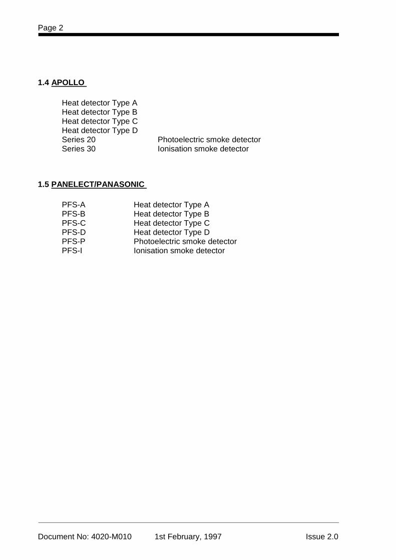
1.4 APOLLO
Heat detector Type A Heat detector Type B Heat detector Type C Heat detector Type D Series 20 Photoelectric smoke detector Series 30 Ionisation smoke detector
1.5 PANELECT/PANASONIC
PFS-A Heat detector Type A PFS-B Heat detector Type B PFS-C Heat detector Type C PFS-D Heat detector Type D PFS-P Photoelectric smoke detector PFS-I Ionisation smoke detector

4020 OPERATORS MANUAL Page 3
Document No: 4020-M010 1st February, 1997 Issue 2.0
2 COMPATIBLE BATTERIES The following series of batteries are compatible with the 4020 FIP: (1) Power-Sonic PS12 series (2) Sonnenschien A200 series (3) Sonnenschien A300 series (4) Yuasa NP series
Page 4
Document No: 4020-M010 1st February, 1997 Issue 2.0
3 SPECIFICATION
3.1 GENERAL System Capacity Minimum 8 Alarm Zone Circuits
Maximum 48 Alarm Zone Circuits Cabinet Size(mm) Up to 24 Zones : 440H x 500W x 140D 24 - 48 Zones : 400H x 535W x 180D Cabinet Material 1.5mm Mild grade steel Cabinet Finish Powder coated Cabinet Colour Magnolia Ripple Mounting Wall mount Shipping Weight 14Kg (without batteries) Mains Input 240V AC, +6%,-10%,50Hz Internal Power Supply 24V DC @ 1.5A, or 24V DC @ 4.5A Standby Battery 24V sealed lead acid 7Ah or 12Ah Battery Charger 27.6V DC (nominal) @ 0.6A, PSU Supervision Charger high/low,Battery low/fail Temperature -5°C to 45°C Humidity 10% to 90% rh non-condensing.
3.2 INPUTS Detector Circuits Standard 20V detectors Maximum detector quiescent current 2.4mA Door Switch Bell Isolate, ACF Isolate Other Supervised door mounted Manual Call Point
3.3 OUTPUTS Bell Supervised 24V DC @ 1.5A Brigade(2) Voltage free relay contacts (2A @ 30V dc) N.O. or N.C.
Power Fail(Fault), Master Alarm Ancillary(2) Voltage free relay contacts (2A @ 30V dc) N.O. or N.C.
3.4 INDICATORS and DISPLAY
Zone Status 2 line by 40 character backlight Liquid Crystal Display with adjustable contrast control
LED Status Indicators Common Alarm, Fault and Isolate Bell Isolated, ACF Isolated, Mains Power ON
Audible Buzzer Alarm And Fault Indications Keypress feedback
4020 OPERATORS MANUAL Page 5
Document No: 4020-M010 1st February, 1997 Issue 2.0
SPECIFICATION (CONTINUED)
3.5 KEYPAD CONTROLS Fire Fighters Keypad NEXT, ACKNOWLEDGE, RESET, ISOLATE, BRIGADE TEST Service Technician 20 keys including:- Alarm Test, Fault Test, Keypad Isolate, Battery Test and Lamp test
3.6 PROGRAMMING FUNCTIONS Input Zone Type Normal, Alarm Verification, AS1668 - 30sec or 60 sec
Latching/non-latching Zone Labels Maximum 27 characters Output Control Input list conditions, delay time, Door Isolate
3.7 COMMUNICATIONS PORT (optional) Type: Serial, 1 x 2120 DC Comms and 1x RS232 Printer port
OR Serial , 1x Mimic and 1 x RS232 Printer port
3.8 EXPANSION CARDS 8 Input Monitor Card 8 alarm zone circuits 4 Point Control Card 4 x N.O. Voltage free relay contacts (2A @ 30V dc)
supervised or unsupervised.
Page 6
Document No: 4020-M010 1st February, 1997 Issue 2.0
4 AMENDMENTS TO 4020 OPERATOR MANUAL
ISSUE
SECTION/PAGES
AMENDED
DATE
AMENDED
COMMENTS
ECN No.
1
NIL
16-09-91
Original
1.1
25-10-91
2.0
Various
1-02-97
Revised for Version 2.0 Firmware File: 4020M010.wp1

4020 OPERATORS MANUAL Page 7
Document No: 4020-M010 1st February, 1997 Issue 2.0
This page intentionally left blank
Page 8
Document No: 4020-M010 1st February, 1997 Issue 2.0
Figure 1 4020 FIP
4020 OPERATORS MANUAL Page 9
Document No: 4020-M010 1st February, 1997 Issue 2.0
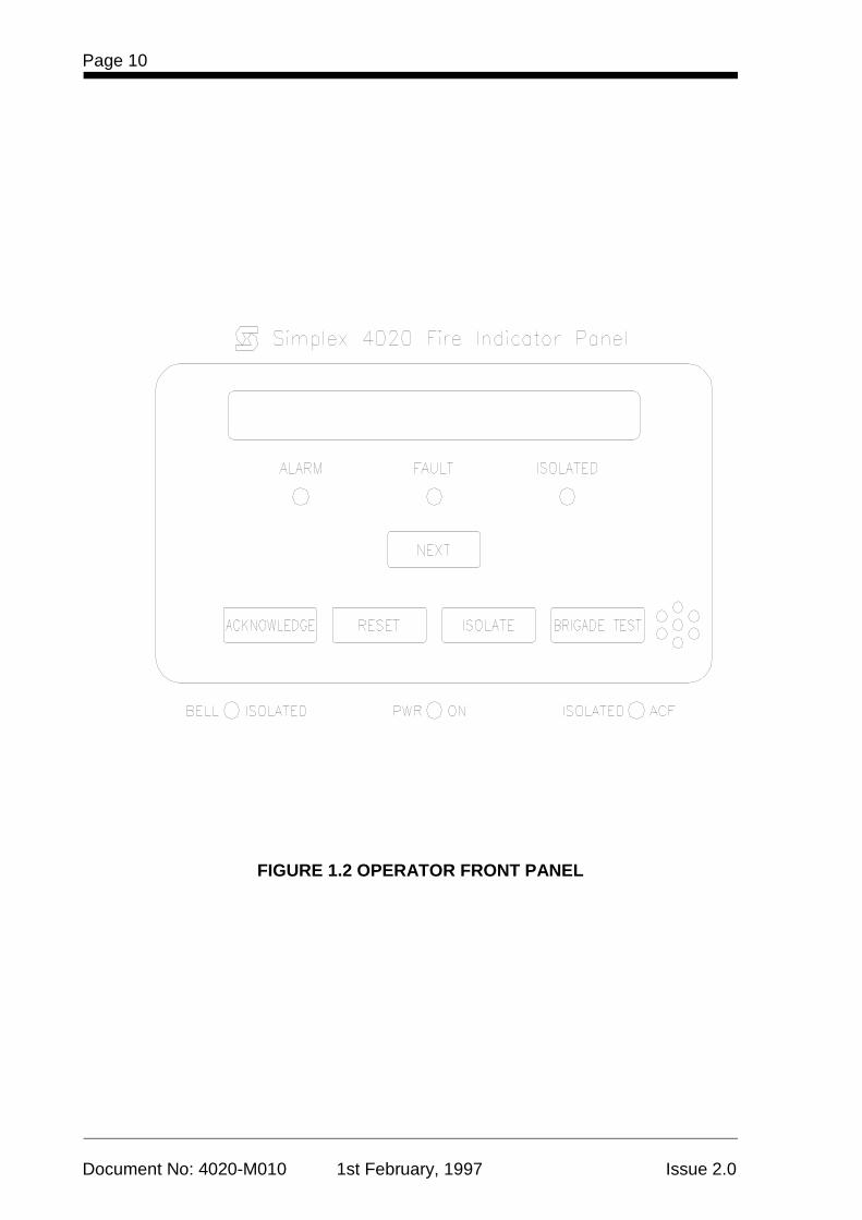
5 INTRODUCTION The Simplex 4020 fire indicator panel is a conventional programmable, microprocessor-controlled unit designed to meet the requirements of AS1603.4. The 4020 FIP can monitor from eight to forty eight fire detection zones and is permanently connected to the Fire Brigade alarm system. The fire detection zones can comprise of conventional thermal or smoke detectors, manual call points, flowswitches ,valve monitor devices etc The operator interface is provided via a 2 line by 40 character LCD display and a membrane type keyboard. LED indicators are provide for indicating common alarm, common fault and common isolate status. The unit is protected against power loss by emergency standby batteries. Figure 1 shows the external view of the 4020 FIP. The alarm, fault and isolate conditions are stored in separate buffer lists. Each list can be called up on the LCD display and scrolled through to view current status. During an alarm, the 4020 panel will initiate a Brigade alarm, operate connected building alarms eg: airconditioning shutdowns, magnetic door release and display a description of the alarm zone, the type of alarm circuit, the number of alarms in the order they were activated, and the time of the first alarm. The unit is self regulatory as it will locate and indicate faults in the system. The fault information displayed includes the zone or circuit, its location, the state of the circuit, the number of faults, and the time the first fault occurred. This unit has been programmed on installation and the alphanumeric display describes the fire detection zones, and warning indicators as installed in this building.
Page 10
Document No: 4020-M010 1st February, 1997 Issue 2.0
FIGURE 1.2 OPERATOR FRONT PANEL
4020 OPERATORS MANUAL Page 11
Document No: 4020-M010 1st February, 1997 Issue 2.0
5.1 OPERATOR FRONT PANEL Figure 1.2 shows the layout of the front panel operator controls. These are described as follows: The Panel buzzer will sound under alarm and fault conditions until silenced during the response procedure. The Audible Positive Feedback Device sounds when any key on the panel is pressed as an indication that the keystroke has been registered. The Alarm light will illuminate when there is an alarm in any one of the zones protected by the system. The Fault light will illuminate when there is a fault in the system at any stage. The Isolated light will only illuminate when the Isolate button is pressed to isolate zones. When any zone is isolated, it will not send any alarm to the master alarm facility and the isolated light will illuminate. The Bell Isolated light will illuminate when the panel door is opened. This isolates the building alarm bell. The Power On light indicates that the 240 V supply is available. If the 240 V supply fails, the system switches to battery supply, the Power On light turns off and the fault light illuminates. The Isolated ACF light (Ancillary Control Facility). The Isolated ACF light will only illuminate if the panel door is opened and there is no alarm present on the panel. The building ancillaries include the air conditioning shut downs, magnetic fire door holders, alarm buzzers, lights, and other outputs. The light indicates that all the ancillary circuits programmed to be isolated via the door switch are isolated when the panel door is opened and there are no alarms present on the panel. The Text Window consists of two lines of text which describe the status of the system in four modes. Normal mode is the normal operational state of the panel. It shows:
SIMPLEX AUSTRALIA - Time of day - Bat: OK Alarms: 0 Faults: 00 Isolated : 00
Page 12
Document No: 4020-M010 1st February, 1997 Issue 2.0
Alarm mode shows the alarm details. For example:
Zn6 Level 4 East V-Smoke Ackd Alarm # 1 of 3 11:27:00
- The top line shows the zone number, a description of the location, and the type
of device on the circuit. - The bottom line shows the status of the alarm at that time, the number of the
displayed alarm and the total number of alarms, and the time the alarm was activated.
The status of the alarm may be "Alarm" or "Normal". Detectors once activated will remain in the "Alarm" state but devices such as flow switches may indicate "Normal" when they are not actually operating. Fault mode shows the fault details. For example:
Zn8 Level 5 West V-Smoke Ackd Fault # 2 of 2 14:38:00
- The top line shows the Zone Number and the fault location description. For
output control circuit faults it would also show "On" or "Off" on the right, indicating the state of the relay before the fault.
- The bottom line shows the status of the fault at that time, the number of the
displayed fault and the total number of faults, and the time the fault occurred. Isolated mode shows the details of isolated circuits or zones. For example:
Zn4 Level 7 Board Room V-Smoke Isol Ackd Alarm # 1 of 2 12:27:00
- The top line shows the Zone Number for input circuits or the Control Point
number for output circuits, the location description, and, for output circuits, the status of the circuit before being isolated.
- The bottom line shows the status of the circuit/zone at that time, the number of
the displayed isolated circuit/zone, the total number of isolated circuits/zones, and the time the circuit/zone was isolated.
4020 OPERATORS MANUAL Page 13
Document No: 4020-M010 1st February, 1997 Issue 2.0
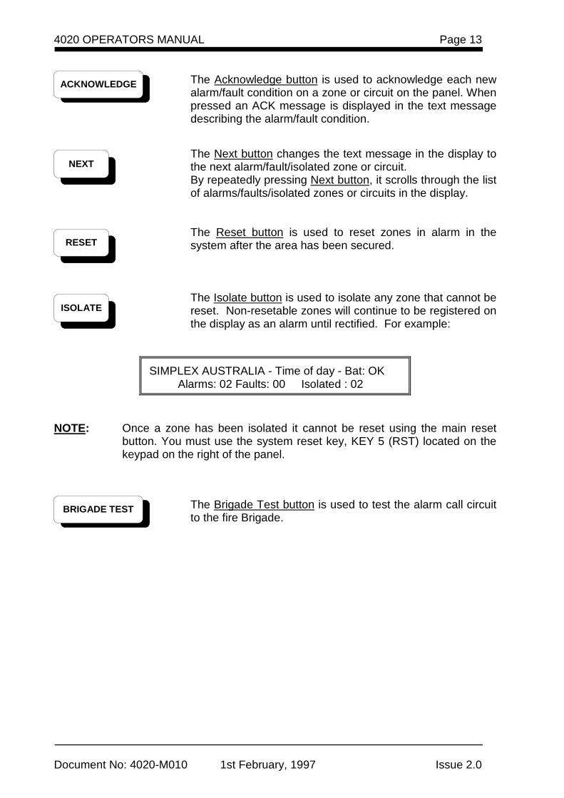
The Acknowledge button is used to acknowledge each new alarm/fault condition on a zone or circuit on the panel. When pressed an ACK message is displayed in the text message describing the alarm/fault condition.
The Next button changes the text message in the display to the next alarm/fault/isolated zone or circuit. By repeatedly pressing Next button, it scrolls through the list of alarms/faults/isolated zones or circuits in the display.
The Reset button is used to reset zones in alarm in the system after the area has been secured.
The Isolate button is used to isolate any zone that cannot be reset. Non-resetable zones will continue to be registered on the display as an alarm until rectified. For example:
SIMPLEX AUSTRALIA - Time of day - Bat: OK Alarms: 02 Faults: 00 Isolated : 02
NOTE: Once a zone has been isolated it cannot be reset using the main reset
button. You must use the system reset key, KEY 5 (RST) located on the keypad on the right of the panel.
The Brigade Test button is used to test the alarm call circuit to the fire Brigade.
ACKNOWLEDGE
BRIGADE TEST
NEXT
RESET
ISOLATE
Page 14
Document No: 4020-M010 1st February, 1997 Issue 2.0
6 ALARM CONDITIONS Under alarm conditions the panel is operated from the buttons located on the main section of the panel. These can be seen through the inspection window. When a detector zone is in alarm, the red alarm LED will be flashing and the panel buzzer will be sounding. To silence the local buzzer the alarm needs to be acknowledged.
6.1 ACKNOWLEDGING ALARMS To acknowledge alarms use the following procedure: STEP 1 Open the panel door. The bell isolated light illuminates because the door
switch has operated which has silenced the alarm bell outside the building.
While the door is opened the alarm light continues flashing and the buzzer still sounds until all alarms are acknowledged.
CAUTION
Do not touch the keypad on the right of the panel as this is for the use of technical staff only.
STEP 2 Read the displayed alarm message.
- The top line of the display is showing location and details of the first alarm which operated.
Zn6 Level 4 East V-Smoke Alarm # 1 of 3 11:27:00
- The left of the bottom line is showing the present state of the zone
or circuit. In the centre, it may be showing 1 of 1 which means there is only one alarm, or it could be showing 1 of 2, or 1 of 3 depending on how many alarms there are. The time the alarm was activated is displayed on the right.
4020 OPERATORS MANUAL Page 15
Document No: 4020-M010 1st February, 1997 Issue 2.0
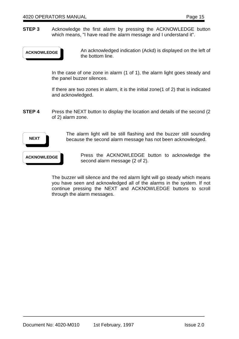
STEP 3 Acknowledge the first alarm by pressing the ACKNOWLEDGE button which means, "I have read the alarm message and I understand it".
An acknowledged indication (Ackd) is displayed on the left of the bottom line.
In the case of one zone in alarm (1 of 1), the alarm light goes steady and the panel buzzer silences.
If there are two zones in alarm, it is the initial zone(1 of 2) that is indicated and acknowledged.
STEP 4 Press the NEXT button to display the location and details of the second (2
of 2) alarm zone.
The alarm light will be still flashing and the buzzer still sounding because the second alarm message has not been acknowledged.
Press the ACKNOWLEDGE button to acknowledge the second alarm message (2 of 2).
The buzzer will silence and the red alarm light will go steady which means you have seen and acknowledged all of the alarms in the system. If not continue pressing the NEXT and ACKNOWLEDGE buttons to scroll through the alarm messages.
ACKNOWLEDGE
ACKNOWLEDGE
NEXT
Page 16
Document No: 4020-M010 1st February, 1997 Issue 2.0
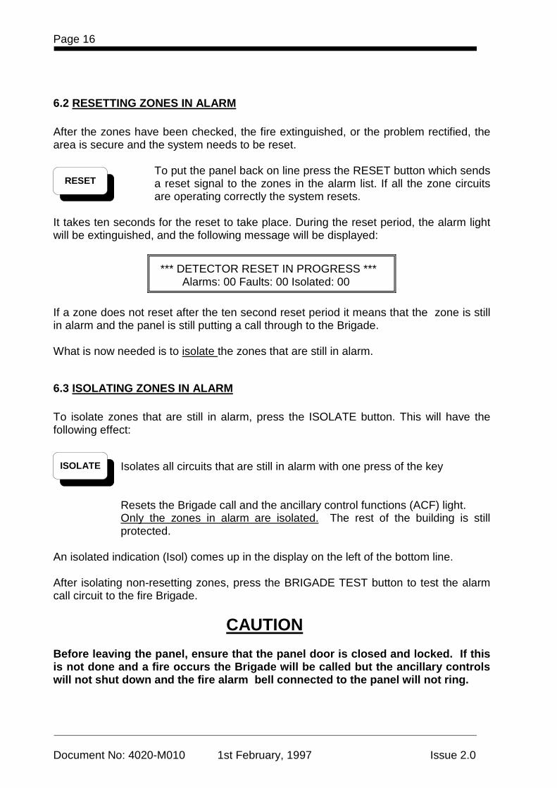
6.2 RESETTING ZONES IN ALARM After the zones have been checked, the fire extinguished, or the problem rectified, the area is secure and the system needs to be reset.
To put the panel back on line press the RESET button which sends a reset signal to the zones in the alarm list. If all the zone circuits are operating correctly the system resets.
It takes ten seconds for the reset to take place. During the reset period, the alarm light will be extinguished, and the following message will be displayed:
*** DETECTOR RESET IN PROGRESS *** Alarms: 00 Faults: 00 Isolated: 00
If a zone does not reset after the ten second reset period it means that the zone is still in alarm and the panel is still putting a call through to the Brigade. What is now needed is to isolate the zones that are still in alarm.
6.3 ISOLATING ZONES IN ALARM To isolate zones that are still in alarm, press the ISOLATE button. This will have the following effect:
Isolates all circuits that are still in alarm with one press of the key
Resets the Brigade call and the ancillary control functions (ACF) light. Only the zones in alarm are isolated. The rest of the building is still protected.
An isolated indication (Isol) comes up in the display on the left of the bottom line. After isolating non-resetting zones, press the BRIGADE TEST button to test the alarm call circuit to the fire Brigade.
CAUTION Before leaving the panel, ensure that the panel door is closed and locked. If this is not done and a fire occurs the Brigade will be called but the ancillary controls will not shut down and the fire alarm bell connected to the panel will not ring.
RESET
ISOLATE
4020 OPERATORS MANUAL Page 17
Document No: 4020-M010 1st February, 1997 Issue 2.0
The service company needs to be called to check why the zone circuits cannot be reset. This is done by the fire Brigade who have a register of every panel and the name of the service company. NOTE: 1. You cannot use the main RESET button to reset zones once they
have been isolated. Instead you need to use the system reset facility, KEY 5(RST) button on the keypad. This should only be used by service company.
2. You cannot reset an alarm on a zone that has gone into fault. You
must first clear the fault on the zone before the alarm can be reset.
Page 18
Document No: 4020-M010 1st February, 1997 Issue 2.0
7 FAULT CONDITIONS When a fault condition occurs, the fault light will be flashing and the panel buzzer sounds. The power on light may or may not be illuminated depending on the fault. The bottom line of the display will indicate the number of faults.
7.1 ACKNOWLEDGING FAULTS
STEP 1 Open the door and the bell isolated light and the ACF isolated light will illuminate.
CAUTION
Do not touch the keypad on the right of the panel as this is for the use of technical staff only.
STEP 2 Press the ESCape key and then the ACKNOWLEDGE button to display
the fault message. The acknowledge (Ackd) indication is shown on the left of the bottom line of the display.eg:
Zn8 Level 5 West V-Smoke Ackd Fault # 1 of 2 14:38:00
- The top line of the display shows the location and details of the first fault which operated.
- The left of the bottom line shows the present state of the zone or
circuit. In the centre, it may show 1 of 1, which means there is only one fault, or it could show 1 of 2, or 1 of 3 depending on how many faults there are. The time the fault was activated is displayed on the right.
If there is only one fault (1 of 1), the fault light will go steady and the buzzer will silence.
If there are two faulty zones, it is the initial fault (1 of 2) that is indicated and acknowledged.
ACKNOWLEDGE
ESC
4020 OPERATORS MANUAL Page 19
Document No: 4020-M010 1st February, 1997 Issue 2.0
STEP 3 If the fault light is still flashing and the buzzer is still sounding, press the NEXT button to show the location and details of the second (2 of 2) fault.
Press the ACKNOWLEDGE button to acknowledge the second fault message (2 of 2).
The buzzer will silence and the fault light will go steady which means you have seen and acknowledged all of the faults in the system. If not, continue pressing the NEXT and ACKNOWLEDGE buttons to scroll through and acknowledge the fault messages.
CAUTION
Before leaving the panel ensure that the panel door is closed and locked. When the door is closed ensure that the BELL ISOLATED and ACF ISOLATED indicators are not ON. If this is not done and a fire occurs, the Brigade will be called but the ancillary controls will not shut down and the building fire bell will not ring.
Refer to list off fault messages in the appendix and ring the service company to have the fault rectified. It is an advantage to take a note of the faults so the service company can be given an idea of the type of problems before they arrive to rectify the fault The fault light will stay on until the fault is rectified but the remainder of the system will still operate normally.
NOTES (1) Alarms always have priority over fault conditions. (2) If a fault condition occurs while viewing alarms, the fault light will be flashing but
the panel buzzer will not sound.
(3) If you exit the alarm list after acknowledging all alarms and unacknowledged faults exist then the buzzer will continue sounding.
To silence the buzzer you must access the fault list by pressing the ESC key and acknowledge each fault. When all faults are acknowledged, the buzzer will silence and the fault light will be ON steady.
ACKNOWLEDGE
NEXT
Page 20
Document No: 4020-M010 1st February, 1997 Issue 2.0
(4) If you receive an alarm while acknowledging faults, you immediately exit the fault
list, the alarm while be displayed, the buzzer will be sounding and the alarm LED will be flashing. The fault LED will still be flashing.
7.2 BUZZER MUTE FACILITY Use the following procedure to mute the panel buzzer. STEP 1 Press the ADD key on the keypad. The following “buzzer mute” message will continually cycle ON and OFF
on the LCD display.
** WARNING - PANEL BUZZER IS DISABLED ** Use ADD key to switch ON or OFF
To restore panel buzzer operation, press the ADD key to remove the buzzer mute function.
NOTE: The panel buzzer cannot be muted for alarm conditions. In the event of a
fire alarm, the buzzer mute function is reset immediately and the panel buzzer will sound.
* ADD

4020 OPERATORS MANUAL Page 21
Document No: 4020-M010 1st February, 1997 Issue 2.0
This page intentionally left blank
Page 22
Document No: 4020-M010 1st February, 1997 Issue 2.0
Figure 1.3 Keypad function keys
4020 OPERATORS MANUAL Page 23
Document No: 4020-M010 1st February, 1997 Issue 2.0
8 COMMISSIONING AND SERVICING
8.1 KEYPAD FUNCTION KEYS The commissioning or testing technician needs to know the function of the following 16 keys ( refer fig 1.3 ):
The 1 to 9 keys The Plus and Minus keys The Escape key The four test keys across the top of the keypad
The following information lists the keypad functions for use during commissioning or testing.
Key 1 is alarm list (ALM LIST) key. It is used to display the alarms present in the system.
Presume the main display menu is in normal mode ie:
SIMPLEX AUSTRALIA - Time of day - Bat: OK Alarms: 05 Faults: 05 Isolated : 05
To look at the alarms, press ALM LIST (1) and it will give access to that list of five alarms. Then use the plus and minus keys to either scroll forward or backwards through that list. This makes it easier when working on the panel. To exit the list press the escape (ESC) key.
Key 2 is fault list (FLT LIST) key. It allows access to the list of faults in the system. The list can be scrolled using the plus and minus keys. To exit the list press the escape (ESC) key.
Using the example above, pressing the FLT LIST (2) allows access to the list of five faults.
1 ALM LIST
2 FLT LIST
Page 24
Document No: 4020-M010 1st February, 1997 Issue 2.0
Key 3 is isolated list (ISO LIST) key. It allows access to the list of isolated circuits. The list can be scrolled using the plus and minus keys. To exit the list press the escape (ESC) key.
Using the example above, pressing the ISO LIST (3) allows access to the list of five isolated alarms.
CAUTION
When working on the system and displaying lists or functions, if an alarm activates, it has priority and will be displayed automatically.
NOTE: Keys 1, 2, and 3
These lists will only register if there is a quantity for that category in the display. ie: If the alarm list is pressed and nothing happens there are no alarms to list.
Key 4 is acknowledge plus (ACK+) key This combines the functions of the acknowledge and next buttons of the main operating panel. When in the alarm or fault lists, it is a quick means of acknowledging faults or alarms when working on the system.
Key 5 is System reset (RST) key This provides a global reset function and will reset all zones including isolated zones. This reset is for use by the technician after an isolated circuit has been repaired.
The RST (5) function can only be used when the display is in NORMAL mode. Press the escape (ESC) key to return to normal display mode.
NOTE: Using the main reset button, only acknowledged alarms can be
reset. If they are isolated they cannot be reset except by using KEY 5 (RST).
3 ISO LIST
4 ACK+
5 RST
4020 OPERATORS MANUAL Page 25
Document No: 4020-M010 1st February, 1997 Issue 2.0
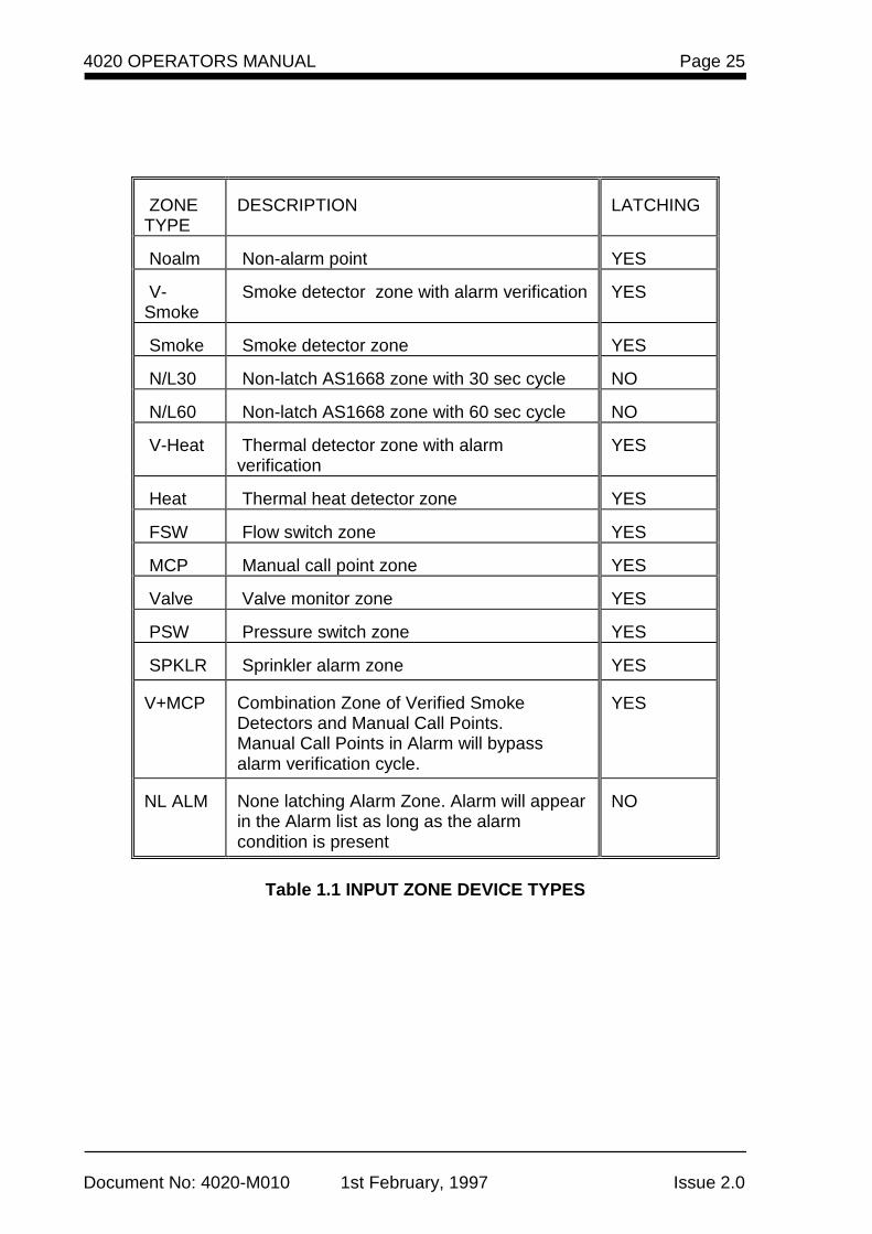
ZONE TYPE
DESCRIPTION
LATCHING
Noalm
Non-alarm point
YES
V-Smoke
Smoke detector zone with alarm verification
YES
Smoke
Smoke detector zone
YES
N/L30
Non-latch AS1668 zone with 30 sec cycle
NO
N/L60
Non-latch AS1668 zone with 60 sec cycle
NO
V-Heat
Thermal detector zone with alarm verification
YES
Heat
Thermal heat detector zone
YES
FSW
Flow switch zone
YES
MCP
Manual call point zone
YES
Valve
Valve monitor zone
YES
PSW
Pressure switch zone
YES
SPKLR
Sprinkler alarm zone
YES
V+MCP
Combination Zone of Verified Smoke Detectors and Manual Call Points. Manual Call Points in Alarm will bypass alarm verification cycle.
YES
NL ALM
None latching Alarm Zone. Alarm will appear in the Alarm list as long as the alarm condition is present
NO
Table 1.1 INPUT ZONE DEVICE TYPES
Page 26
Document No: 4020-M010 1st February, 1997 Issue 2.0
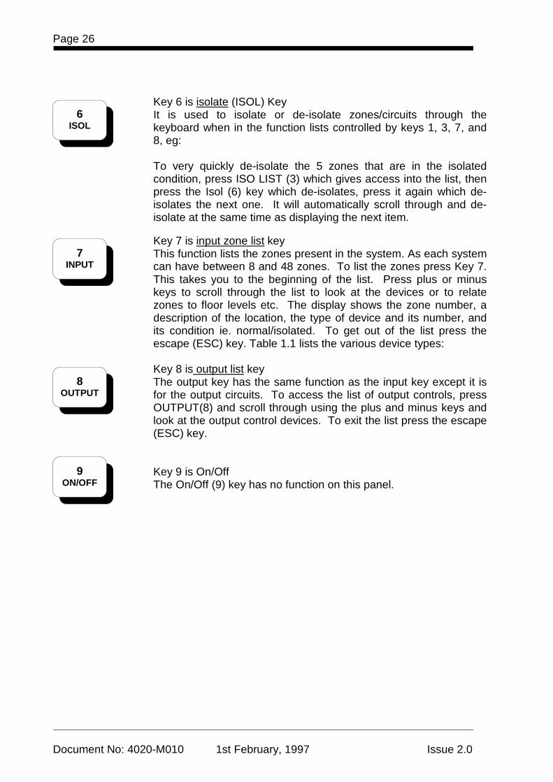
Key 6 is isolate (ISOL) Key It is used to isolate or de-isolate zones/circuits through the keyboard when in the function lists controlled by keys 1, 3, 7, and 8, eg:
To very quickly de-isolate the 5 zones that are in the isolated condition, press ISO LIST (3) which gives access into the list, then press the Isol (6) key which de-isolates, press it again which de-isolates the next one. It will automatically scroll through and de-isolate at the same time as displaying the next item.
Key 7 is input zone list key This function lists the zones present in the system. As each system can have between 8 and 48 zones. To list the zones press Key 7. This takes you to the beginning of the list. Press plus or minus keys to scroll through the list to look at the devices or to relate zones to floor levels etc. The display shows the zone number, a description of the location, the type of device and its number, and its condition ie. normal/isolated. To get out of the list press the escape (ESC) key. Table 1.1 lists the various device types:
Key 8 is output list key The output key has the same function as the input key except it is for the output circuits. To access the list of output controls, press OUTPUT(8) and scroll through using the plus and minus keys and look at the output control devices. To exit the list press the escape (ESC) key.
Key 9 is On/Off The On/Off (9) key has no function on this panel.
6 ISOL
7 INPUT
8 OUTPUT
9 ON/OFF
4020 OPERATORS MANUAL Page 27
Document No: 4020-M010 1st February, 1997 Issue 2.0
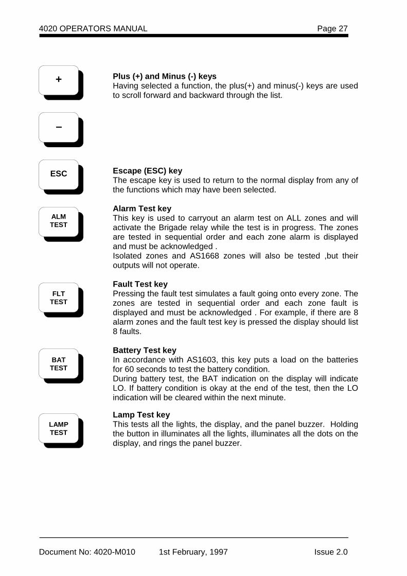
Plus (+) and Minus (-) keys Having selected a function, the plus(+) and minus(-) keys are used to scroll forward and backward through the list.
Escape (ESC) key The escape key is used to return to the normal display from any of the functions which may have been selected.
Alarm Test key This key is used to carryout an alarm test on ALL zones and will activate the Brigade relay while the test is in progress. The zones are tested in sequential order and each zone alarm is displayed and must be acknowledged . Isolated zones and AS1668 zones will also be tested ,but their outputs will not operate.
Fault Test key Pressing the fault test simulates a fault going onto every zone. The zones are tested in sequential order and each zone fault is displayed and must be acknowledged . For example, if there are 8 alarm zones and the fault test key is pressed the display should list 8 faults.
Battery Test key In accordance with AS1603, this key puts a load on the batteries for 60 seconds to test the battery condition. During battery test, the BAT indication on the display will indicate LO. If battery condition is okay at the end of the test, then the LO indication will be cleared within the next minute.
Lamp Test key This tests all the lights, the display, and the panel buzzer. Holding the button in illuminates all the lights, illuminates all the dots on the display, and rings the panel buzzer.
+
−−−−
ESC
ALM TEST
FLT
TEST
BAT TEST
LAMP TEST
Page 28
Document No: 4020-M010 1st February, 1997 Issue 2.0
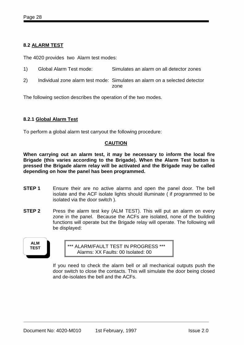
8.2 ALARM TEST The 4020 provides two Alarm test modes: 1) Global Alarm Test mode: Simulates an alarm on all detector zones 2) Individual zone alarm test mode: Simulates an alarm on a selected detector zone The following section describes the operation of the two modes.
8.2.1 Global Alarm Test To perform a global alarm test carryout the following procedure: CAUTION When carrying out an alarm test, it may be necessary to inform the local fire Brigade (this varies according to the Brigade). When the Alarm Test button is pressed the Brigade alarm relay will be activated and the Brigade may be called depending on how the panel has been programmed. STEP 1 Ensure their are no active alarms and open the panel door. The bell
isolate and the ACF isolate lights should illuminate ( if programmed to be isolated via the door switch ).
STEP 2 Press the alarm test key (ALM TEST). This will put an alarm on every
zone in the panel. Because the ACFs are isolated, none of the building functions will operate but the Brigade relay will operate. The following will be displayed:
*** ALARM/FAULT TEST IN PROGRESS *** Alarms: XX Faults: 00 Isolated: 00
If you need to check the alarm bell or all mechanical outputs push the
door switch to close the contacts. This will simulate the door being closed and de-isolates the bell and the ACFs.
ALM TEST
4020 OPERATORS MANUAL Page 29
Document No: 4020-M010 1st February, 1997 Issue 2.0
STEP 3 Press the ACK+ (4) key to acknowledge each displayed alarm.
If ACFs are not isolated, check that all the building controls work, the bell rings, the air conditioning will shut down, the magnetic door holders will close fire doors, etc.
STEP 4 Reset the circuits by pressing the ESC key to exit the alarm list and then
press the RST (5) key or by using the main acknowledge/next/reset buttons. The following will be displayed:
*** DETECTOR RESET IN PROGRESS *** Alarms: 00 Faults: 00 Isolated: 00
8.2.2 Individual Zone Alarm Test To perform an individual zone alarm test carryout the following procedure: CAUTION When carrying out an alarm test, it may be necessary to inform the local fire Brigade (this varies according to the Brigade). When the Alarm Test button is pressed the Brigade alarm relay will be activated and the Brigade may be called dependant upon how the system has been programmed. STEP 1 Ensure their are no active alarms and open the panel door. The bell
isolate and the ACF isolate lights should illuminate. STEP 2 Select the required alarm zone by pressing the zone input key 7. STEP 3 Use the + / - keys to display the required zone
STEP 4 Press the alarm test key (ALM TEST).
4 ACK+
5 RST
7 INPUT
+
_
Page 30
Document No: 4020-M010 1st February, 1997 Issue 2.0
This will simulate an alarm on the displayed zone. The panel buzzer will sound and the alarm LED will be flashing. Because the ACFs are isolated, none of the building functions will operate but the Brigade relay will still operate .
If you need to check the alarm bell or all mechanical outputs push the door switch to close the contacts. This will simulate the door being closed and de-isolates the bell and the ACFs.
STEP 5 Press the ACK+ (4) key to acknowledge the displayed alarm.
If ACFs are not isolated, check that all the building controls work, the bell rings, the air conditioning will shut down, the magnetic door holders will close fire doors, etc.
STEP 6 Reset the circuits by pressing the ESC key to exit the alarm list and then
press the RST (5) key or by using the main acknowledge/next/reset buttons. The following will be displayed:
*** DETECTOR RESET IN PROGRESS *** Alarms: 00 Faults: 00 Isolated: 00
ALM TEST
4 ACK+
5 RST
4020 OPERATORS MANUAL Page 31
Document No: 4020-M010 1st February, 1997 Issue 2.0
8.3 FAULT TEST
STEP 1 Open the panel door and press FLT TEST. A fault condition will be simulated on every zone and the following message displayed:
*** ALARM/FAULT TEST IN PROGRESS *** Alarms: 00 Faults: XX Isolated: 00
STEP 2 To acknowledge each fault, press FLT LIST(2) key) to access the fault list
and then press the ACK+ key (4) to acknowledge each fault. The panel buzzer will stop once all faults are acknowledged.
STEP 3 To remove the simulated faults, press the ESC key to exit the fault list and then press the RST(5) key to reset the system.
*** DETECTOR RESET IN PROGRESS *** Alarms: 00 Faults: 00 Isolated: 00
8.4 ISOLATING / DE-ISOLATING CIRCUITS If work is planned near detectors (sanding etc.) they need to be isolated otherwise the dust and grit may cause an alarm. Also output ACF zones may need to be isolated when servicing the panel. When a zone is isolated it will still register an alarm and indicate on the panel but will be prevented from activating the Brigade relay or any associated control outputs. Zones can be isolated/de-isolated using the following procedure: STEP 1 If the display is not in normal mode, press the ESC key on the right-hand
keypad to return the panel the normal display mode. STEP 2 Press the ISOLATE key on the main keypad.
FLT TEST
5 RST
ISOLATE
2
FLT LIST
4
ACK+
Page 32
Document No: 4020-M010 1st February, 1997 Issue 2.0
STEP 3 Using the NEXT key , or + or - keys, cycle through the alarm zones until
the selected zone is displayed.
STEP 4 When the selected zone is displayed, press the ISOLATE key in the main
keypad to isolate the zone. If the zone is already isolated, this will de-isolate the zone and return it to
normal operation.
Alternatively zones can be isolated/de-isolated as follows. STEP 1 Press the INPUT(7) key to access the zone input list or OUTPUT(8) key to
access the output control list STEP 2 Scroll through the list using the PLUS(+) or MINUS(-) key and press the
ISOL(6) key when the selected zone or output is displayed. If the zone is already isolated, pressing the ISOLate key will de-isolate it.
STEP 3 To return to the normal display press escape (ESC).
The display will now indicate the number of zones isolated.
SIMPLEX AUSTRALIA - Time of day - Bat: OK Alarms: 00 Faults: 00 Isolated : XX
6
ISOL
ESC
NEXT
7
INPUT
+
8
OUTPUT
_
ISOLATE
4020 OPERATORS MANUAL Page 33
Document No: 4020-M010 1st February, 1997 Issue 2.0
8.5 OPERATION OF NON-LATCH AS1668 ZONES Zones programmed as non-latching AS1668 zones must be in continual alarm before they operate their associated outputs. When operated, the outputs will track the alarm input and will be de-activated when the monitoring zone has been in a non-alarm condition for a period of either 30 or 60 seconds. Refer to the appendix for more detailed description of AS 1668 zone operation.
8.5.1 Displaying the Status of AS1668 Zones Zones configured with AS1668 delays will not bring-up an alarm condition nor will they be entered into the alarm list when they are in alarm. To display the status of a AS1668 zone use the following steps: STEP 1 Press the INPUT(7) key to display the zone input list and use the +/- keys
to scroll through the list until the zone is displayed.
Zn6 Level 4 East - Supply Air N/L30 Normal # 1 of 3 11:27:00
If an alarm is present on the zone the displayed status will alternate between ALARM and NORMAL condition, tracking the state of the detector zone as it is continually being reset and then checked for an alarm condition.
7
INPUT
Page 34
Document No: 4020-M010 1st February, 1997 Issue 2.0
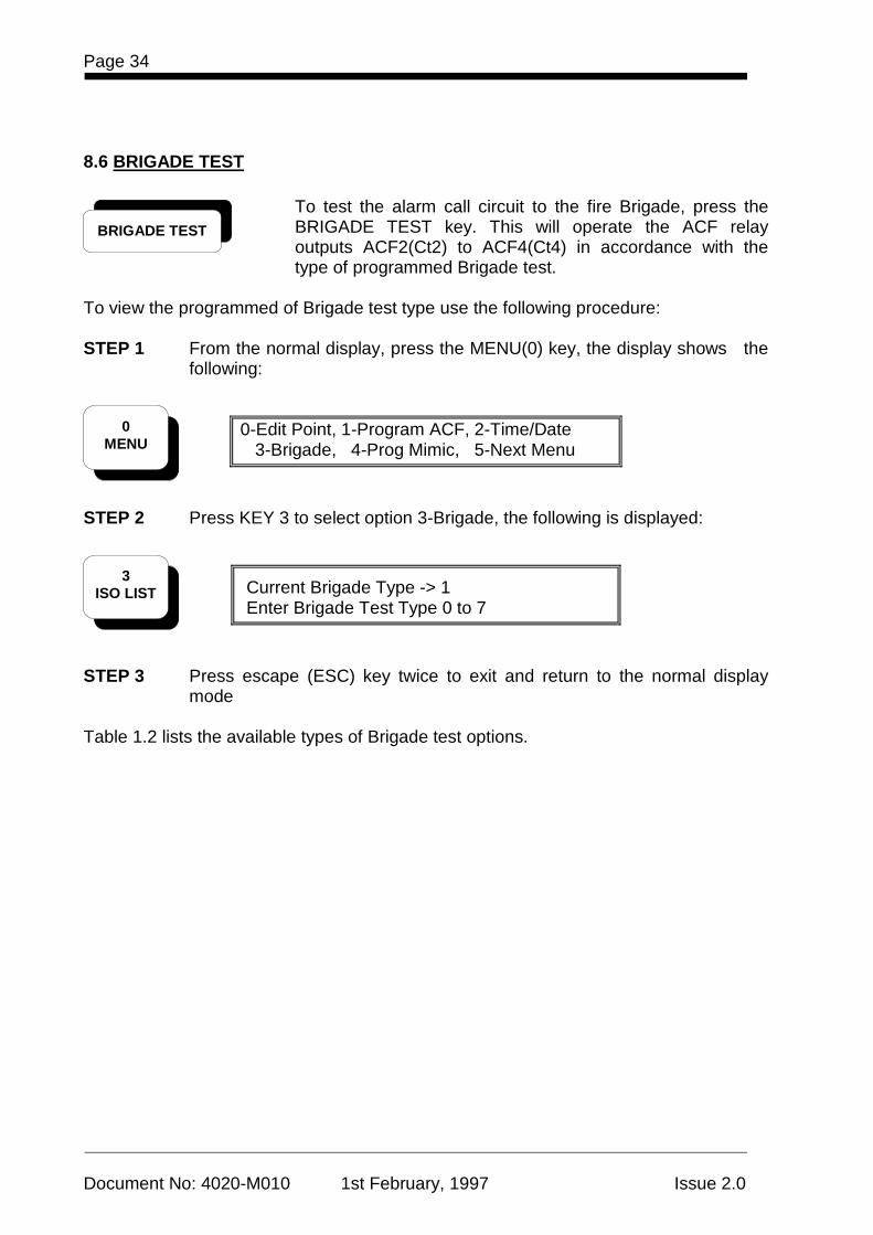
8.6 BRIGADE TEST
To test the alarm call circuit to the fire Brigade, press the BRIGADE TEST key. This will operate the ACF relay outputs ACF2(Ct2) to ACF4(Ct4) in accordance with the type of programmed Brigade test.
To view the programmed of Brigade test type use the following procedure: STEP 1 From the normal display, press the MENU(0) key, the display shows the
following:
0-Edit Point, 1-Program ACF, 2-Time/Date 3-Brigade, 4-Prog Mimic, 5-Next Menu
STEP 2 Press KEY 3 to select option 3-Brigade, the following is displayed:
Current Brigade Type -> 1 Enter Brigade Test Type 0 to 7
STEP 3 Press escape (ESC) key twice to exit and return to the normal display
mode Table 1.2 lists the available types of Brigade test options.
0 MENU
3 ISO LIST
BRIGADE TEST
4020 OPERATORS MANUAL Page 35
Document No: 4020-M010 1st February, 1997 Issue 2.0
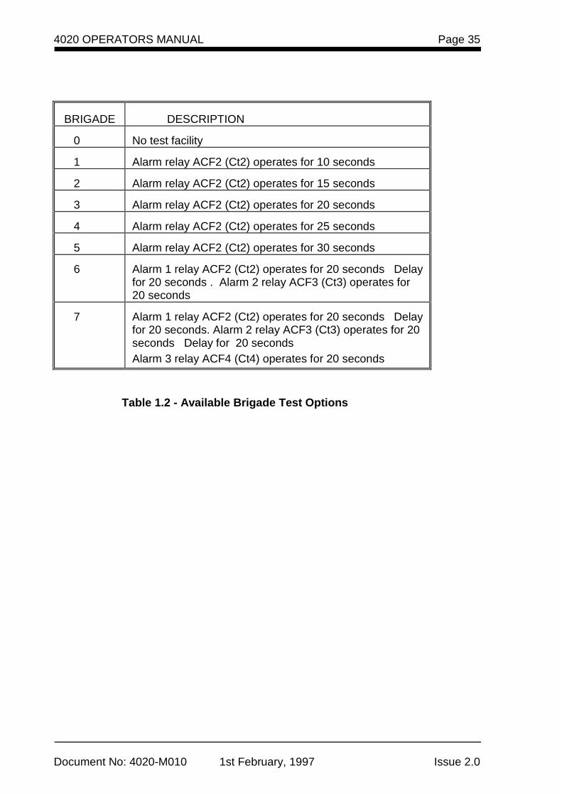
BRIGADE
DESCRIPTION
0
No test facility
1
Alarm relay ACF2 (Ct2) operates for 10 seconds
2
Alarm relay ACF2 (Ct2) operates for 15 seconds
3
Alarm relay ACF2 (Ct2) operates for 20 seconds
4
Alarm relay ACF2 (Ct2) operates for 25 seconds
5
Alarm relay ACF2 (Ct2) operates for 30 seconds
6
Alarm 1 relay ACF2 (Ct2) operates for 20 seconds Delay for 20 seconds . Alarm 2 relay ACF3 (Ct3) operates for 20 seconds
7
Alarm 1 relay ACF2 (Ct2) operates for 20 seconds Delay for 20 seconds. Alarm 2 relay ACF3 (Ct3) operates for 20 seconds Delay for 20 seconds Alarm 3 relay ACF4 (Ct4) operates for 20 seconds
Table 1.2 - Available Brigade Test Options
Page 36
Document No: 4020-M010 1st February, 1997 Issue 2.0
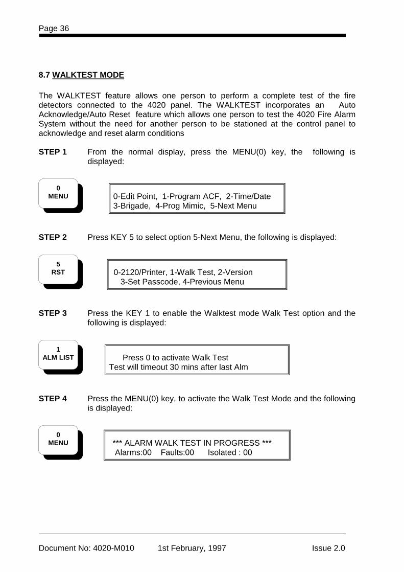
8.7 WALKTEST MODE The WALKTEST feature allows one person to perform a complete test of the fire detectors connected to the 4020 panel. The WALKTEST incorporates an Auto Acknowledge/Auto Reset feature which allows one person to test the 4020 Fire Alarm System without the need for another person to be stationed at the control panel to acknowledge and reset alarm conditions STEP 1 From the normal display, press the MENU(0) key, the following is
displayed:
0-Edit Point, 1-Program ACF, 2-Time/Date 3-Brigade, 4-Prog Mimic, 5-Next Menu
STEP 2 Press KEY 5 to select option 5-Next Menu, the following is displayed:
0-2120/Printer, 1-Walk Test, 2-Version 3-Set Passcode, 4-Previous Menu
STEP 3 Press the KEY 1 to enable the Walktest mode Walk Test option and the
following is displayed:
Press 0 to activate Walk Test Test will timeout 30 mins after last Alm
STEP 4 Press the MENU(0) key, to activate the Walk Test Mode and the following
is displayed:
*** ALARM WALK TEST IN PROGRESS *** Alarms:00 Faults:00 Isolated : 00
0 MENU
5 RST
1 ALM LIST
0 MENU
4020 OPERATORS MANUAL Page 37
Document No: 4020-M010 1st February, 1997 Issue 2.0
NOTES: 1 You can press KEY 5 (RST) key to abort the walk test at any time
before the test timeout expires.
2 All results of the Walk test are stored in the Alarm log and logged to a Serial Printer if connected. The Alarm Log can have up to 99 entries.
3 The Detector reset time is set to 10 seconds and Alarm Verification
is bypassed.
4 When a zone is put into alarm during Walktest, any associated ACF circuits will not operate.
5 The Brigade alarm output will not operate during Walktest Mode.
Hence the panel is effectively disconnected from the Brigade during Walktest mode. Therefore ensure you press KEY 5 (RST) key to abort the walk test at any time before the test timeout expires.
Page 38
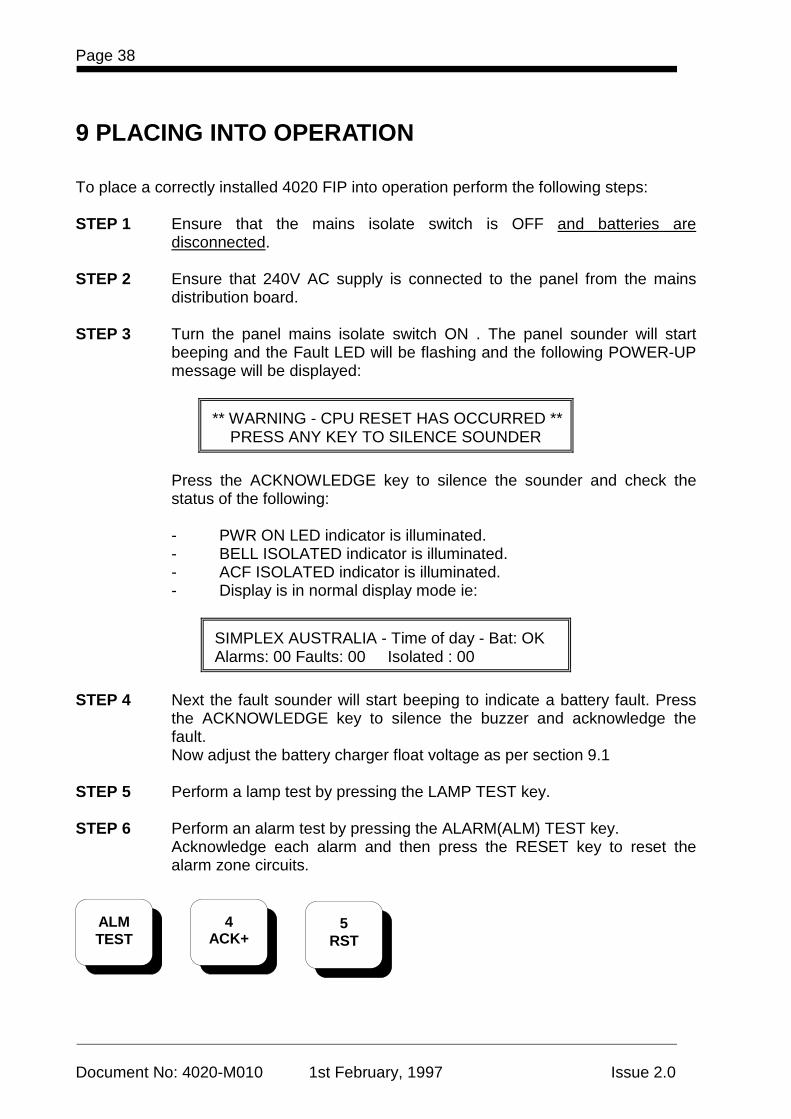
Document No: 4020-M010 1st February, 1997 Issue 2.0
9 PLACING INTO OPERATION To place a correctly installed 4020 FIP into operation perform the following steps: STEP 1 Ensure that the mains isolate switch is OFF and batteries are
disconnected. STEP 2 Ensure that 240V AC supply is connected to the panel from the mains
distribution board. STEP 3 Turn the panel mains isolate switch ON . The panel sounder will start
beeping and the Fault LED will be flashing and the following POWER-UP message will be displayed:
** WARNING - CPU RESET HAS OCCURRED ** PRESS ANY KEY TO SILENCE SOUNDER
Press the ACKNOWLEDGE key to silence the sounder and check the status of the following:
- PWR ON LED indicator is illuminated. - BELL ISOLATED indicator is illuminated. - ACF ISOLATED indicator is illuminated. - Display is in normal display mode ie:
SIMPLEX AUSTRALIA - Time of day - Bat: OK Alarms: 00 Faults: 00 Isolated : 00
STEP 4 Next the fault sounder will start beeping to indicate a battery fault. Press
the ACKNOWLEDGE key to silence the buzzer and acknowledge the fault. Now adjust the battery charger float voltage as per section 9.1
STEP 5 Perform a lamp test by pressing the LAMP TEST key. STEP 6 Perform an alarm test by pressing the ALARM(ALM) TEST key.
Acknowledge each alarm and then press the RESET key to reset the alarm zone circuits.
ALM TEST
4 ACK+
5 RST
4020 OPERATORS MANUAL Page 39
Document No: 4020-M010 1st February, 1997 Issue 2.0
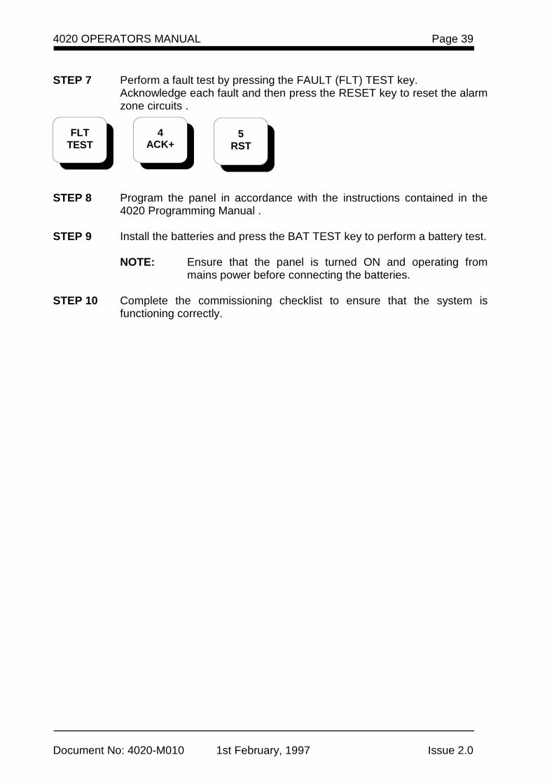
STEP 7 Perform a fault test by pressing the FAULT (FLT) TEST key.
Acknowledge each fault and then press the RESET key to reset the alarm zone circuits .
STEP 8 Program the panel in accordance with the instructions contained in the
4020 Programming Manual . STEP 9 Install the batteries and press the BAT TEST key to perform a battery test.
NOTE: Ensure that the panel is turned ON and operating from
mains power before connecting the batteries. STEP 10 Complete the commissioning checklist to ensure that the system is
functioning correctly.
FLT TEST
4 ACK+
5 RST
Page 40
Document No: 4020-M010 1st February, 1997 Issue 2.0
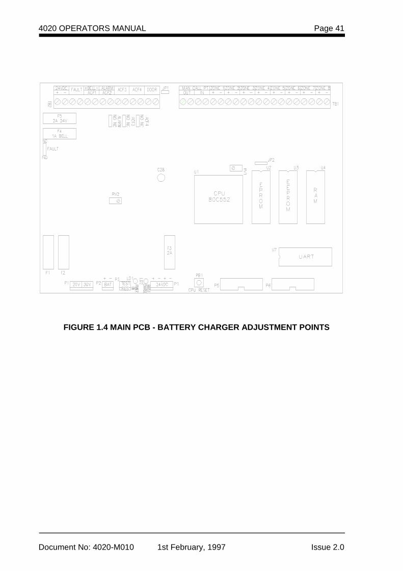
9.1 SETTING BATTERY CHARGER OUTPUT VOLTAGE: To set the battery charger output voltage to the correct level and set the thresholds for battery charger high and low fault conditions, use the following procedure:(Figure 1.4 shows the location of adjustment points). STEP 1 Ensure the batteries are disconnected. STEP 2 Adjust potentiometer RV2 to set the voltage across the battery charger
terminals to 27.6V DC STEP 3 Locate potentiometer RV1 on the main PCB and press the CPU RESET
switch located on the main PCB to clear the current BATtery fault condition due to battery removal.
STEP 4 Turn RV1 anti-clockwise until a BATtery HI condition is indicated on the
display. If the battery fault condition is brought up before completing this step, press the CPU RESET switch and continue the adjustment.
STEP 5 Press the CPU RESET switch .Then adjusting RV1 clockwise ,count the
number of turns until a BATtery LO condition is indicated on the display.
NOTE: If the battery fault condition is brought up before completing this step, press the CPU RESET switch and continue the adjustment.
STEP 6 Then turn RV1 anti-clockwise by half the number of turns obtained in step
5. The display should now indicate BATtery OK condition.
NOTE: If the battery fault condition is brought up before completing this step, press the CPU RESET switch and continue the adjustment.
STEP 7 Re-connect the batteries and press the CPU RESET switch to reset the
system.
CAUTION - POWERING REQUIREMENT
When removing power from the panel, disconnect batteries FIRST and AC power last. When connecting power to the system, connect AC power FIRST and batteries last.
4020 OPERATORS MANUAL Page 41
Document No: 4020-M010 1st February, 1997 Issue 2.0
FIGURE 1.4 MAIN PCB - BATTERY CHARGER ADJUSTMENT POINTS

Page 42
Document No: 4020-M010 1st February, 1997 Issue 2.0
9.2 COMMISSIONING CHECKLIST Check each item to ensure that system has been installed correctly and is functioning normally.
ITEM
CHECKED
Panel configuration as per specification
Cabinet undamaged and paintwork clean
Window undamaged and fitted correctly
Manual Call Point fitted and wired to alarm zone 1
Cabinet sealed to dust level.
Membrane keyboard fitted and aligned correctly
LCD display fitted and aligned correctly
LED indicators fitted and aligned correctly
Keylock type 003 fitted
"Mains Isolation" switch is labelled
Mains terminations correct and earth terminations secure
Internal wiring correct and neatly loomed
Bell fuse F4 fitted and rated at 1A
External 24V DC fuse F5 fitted and rated at 2A
Panel ratings label completed and affixed to panel
Battery terminals insulated
System wired to "as installed drawings"
Log book installed in cabinet
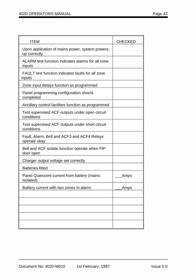
4020 OPERATORS MANUAL Page 43
Document No: 4020-M010 1st February, 1997 Issue 2.0
ITEM
CHECKED
Upon application of mains power, system powers- up correctly
ALARM test function indicates alarms for all zone inputs
FAULT test function indicates faults for all zone inputs
Zone input delays function as programmed
Panel programming configuration sheets completed
Ancillary control facilities function as programmed
Test supervised ACF outputs under open circuit conditions
Test supervised ACF outputs under short circuit conditions
Fault, Alarm, Bell and ACF3 and ACF4 Relays operate okay
Bell and ACF isolate function operate when FIP door open
Charger output voltage set correctly
Batteries fitted
Panel Quiescent current from battery (mains isolated):
___Amps
Battery current with two zones in alarm:
___Amps
Page 44
Document No: 4020-M010 1st February, 1997 Issue 2.0
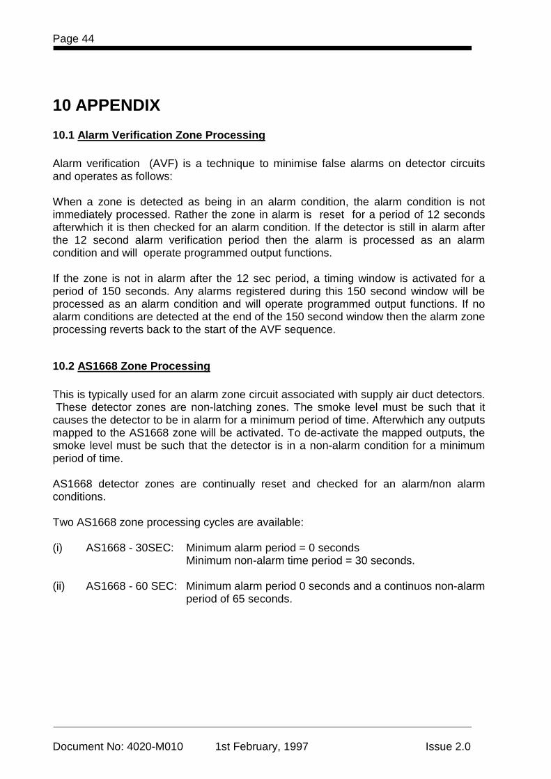
10 APPENDIX
10.1 Alarm Verification Zone Processing Alarm verification (AVF) is a technique to minimise false alarms on detector circuits and operates as follows: When a zone is detected as being in an alarm condition, the alarm condition is not immediately processed. Rather the zone in alarm is reset for a period of 12 seconds afterwhich it is then checked for an alarm condition. If the detector is still in alarm after the 12 second alarm verification period then the alarm is processed as an alarm condition and will operate programmed output functions. If the zone is not in alarm after the 12 sec period, a timing window is activated for a period of 150 seconds. Any alarms registered during this 150 second window will be processed as an alarm condition and will operate programmed output functions. If no alarm conditions are detected at the end of the 150 second window then the alarm zone processing reverts back to the start of the AVF sequence.
10.2 AS1668 Zone Processing This is typically used for an alarm zone circuit associated with supply air duct detectors. These detector zones are non-latching zones. The smoke level must be such that it causes the detector to be in alarm for a minimum period of time. Afterwhich any outputs mapped to the AS1668 zone will be activated. To de-activate the mapped outputs, the smoke level must be such that the detector is in a non-alarm condition for a minimum period of time. AS1668 detector zones are continually reset and checked for an alarm/non alarm conditions. Two AS1668 zone processing cycles are available: (i) AS1668 - 30SEC: Minimum alarm period = 0 seconds Minimum non-alarm time period = 30 seconds. (ii) AS1668 - 60 SEC: Minimum alarm period 0 seconds and a continuos non-alarm
period of 65 seconds.
4020 OPERATORS MANUAL Page 45
Document No: 4020-M010 1st February, 1997 Issue 2.0
10.3 Fault Conditions The table below lists the various fault messages displayed by 4020 FIP FAULT MESSAGE
CAUSE OF FAULT
FAULT RECTIFICATION
Fire Alarm Zone FAULT
Open Circuit on Fire Alarm Zone - Missing End-of-Line resistor. - Break in zone cabling - Detector removed from base
Check Detectors in zone. If all detectors installed Call service company for repair.
Bat :FLT Battery Fault
Batteries disconnected from Charger circuit.
Reconnect batteries to the panel.
Bat: LO
Battery Voltage is Low - Battery charger not working, - Batteries being charged after panel has been operating for extended period on battery supply
Check battery voltage. Check if booster LED is "ON" . If LO condition is indicated for more than 8 Hours call service company.
Bat: HI
Battery charger voltage is set too high.
Remove batteries and check charger voltage, should be 27.6 VDC. Refer section 9.3 for battery adjustment. Check battery charger fuse F2.
Control Circuit Open
Open circuit detected on supervised control circuit output.
Missing End-of-line resistor. - break in cabling - output Fuse blown. Check and replace.
Control Circuit Short
Short circuit detected on supervised control circuit
Blocking diode missing/or wired incorrectly for supervised load. Short on zone cabling
Ground Fault
Short to Earth on external field wiring
Check external field wiring for short to earth connection.

Page 46
Document No: 4020-M010 1st February, 1997 Issue 2.0
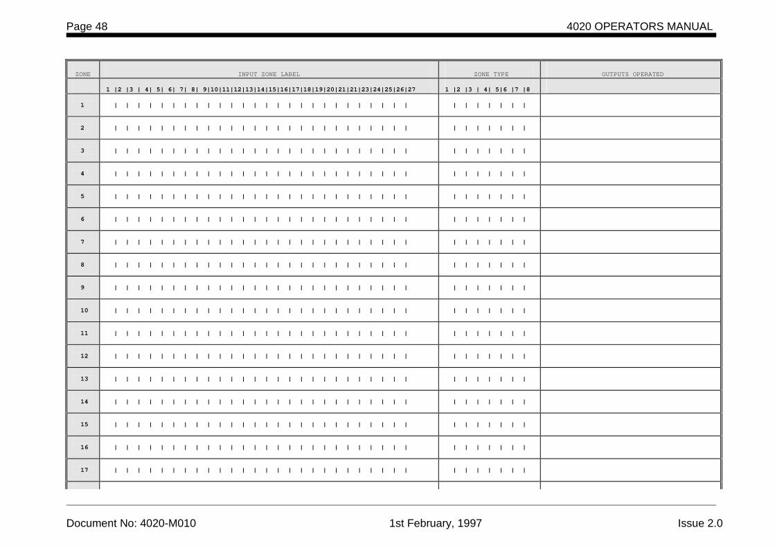
11 PROGRAMMING SHEETS
Complete the programming sheets, which follow, in full. We suggest you use pencil so that future additions or changes may be simply made. Refer to the 4020 Programming Manaul for details on how complete the programming sheets. Once you have programmed the system we suggest that you utilise the INPUT (7) and OUTPUT (8) keys to scroll through the point type and label information to check your program. In addition the system must be comprehensively tested to ensure system functionality.

4020 OPERATORS MANUAL Page 47
Document No: 4020-M010 1st February, 1997 Issue 2.0
This page intentionally left blank.
Page 48 4020 OPERATORS MANUAL
Document No: 4020-M010 1st February, 1997 Issue 2.0
ZONE
INPUT ZONE LABEL
ZONE TYPE
OUTPUTS OPERATED
1 |2 |3 | 4| 5| 6| 7| 8| 9|10|11|12|13|14|15|16|17|18|19|20|21|21|23|24|25|26|27
1 |2 |3 | 4| 5|6 |7 |8
1
| | | | | | | | | | | | | | | | | | | | | | | | | |
| | | | | | |
2
| | | | | | | | | | | | | | | | | | | | | | | | | |
| | | | | | |
3
| | | | | | | | | | | | | | | | | | | | | | | | | |
| | | | | | |
4
| | | | | | | | | | | | | | | | | | | | | | | | | |
| | | | | | |
5
| | | | | | | | | | | | | | | | | | | | | | | | | |
| | | | | | |
6
| | | | | | | | | | | | | | | | | | | | | | | | | |
| | | | | | |
7
| | | | | | | | | | | | | | | | | | | | | | | | | |
| | | | | | |
8
| | | | | | | | | | | | | | | | | | | | | | | | | |
| | | | | | |
9
| | | | | | | | | | | | | | | | | | | | | | | | | |
| | | | | | |
10
| | | | | | | | | | | | | | | | | | | | | | | | | |
| | | | | | |
11
| | | | | | | | | | | | | | | | | | | | | | | | | |
| | | | | | |
12
| | | | | | | | | | | | | | | | | | | | | | | | | |
| | | | | | |
13
| | | | | | | | | | | | | | | | | | | | | | | | | |
| | | | | | |
14
| | | | | | | | | | | | | | | | | | | | | | | | | |
| | | | | | |
15
| | | | | | | | | | | | | | | | | | | | | | | | | |
| | | | | | |
16
| | | | | | | | | | | | | | | | | | | | | | | | | |
| | | | | | |
17
| | | | | | | | | | | | | | | | | | | | | | | | | |
| | | | | | |
4020 OPERATORS MANUAL Page 49
Document No: 4020-M010 1st February, 1997 Issue 2.0
ZONE
INPUT ZONE LABEL
ZONE TYPE
OUTPUTS OPERATED
18 | | | | | | | | | | | | | | | | | | | | | | | | | | | | | | | | |
19
| | | | | | | | | | | | | | | | | | | | | | | | | |
| | | | | | |
20
| | | | | | | | | | | | | | | | | | | | | | | | | |
| | | | | | |
21
| | | | | | | | | | | | | | | | | | | | | | | | | |
| | | | | | |
22
| | | | | | | | | | | | | | | | | | | | | | | | | |
| | | | | | |
23
| | | | | | | | | | | | | | | | | | | | | | | | | |
| | | | | | |
24
| | | | | | | | | | | | | | | | | | | | | | | | | |
| | | | | | |
ZONE
INPUT ZONE LABEL
ZONE TYPE
OUTPUTS OPERATED
1 |2 |3 | 4| 5| 6| 7| 8| 9|10|11|12|13|14|15|16|17|18|19|20|21|21|23|24|25|26|27
1 |2 |3 | 4| 5|6 |7 |8
25
| | | | | | | | | | | | | | | | | | | | | | | | | |
| | | | | | |
26
| | | | | | | | | | | | | | | | | | | | | | | | | |
| | | | | | |
27
| | | | | | | | | | | | | | | | | | | | | | | | | |
| | | | | | |
28
| | | | | | | | | | | | | | | | | | | | | | | | | |
| | | | | | |
29
| | | | | | | | | | | | | | | | | | | | | | | | | |
| | | | | | |
30
| | | | | | | | | | | | | | | | | | | | | | | | | |
| | | | | | |
31
| | | | | | | | | | | | | | | | | | | | | | | | | |
| | | | | | |
32
| | | | | | | | | | | | | | | | | | | | | | | | | |
| | | | | | |
33
| | | | | | | | | | | | | | | | | | | | | | | | | |
| | | | | | |
Page 50 4020 OPERATORS MANUAL
Document No: 4020-M010 1st February, 1997 Issue 2.0
ZONE
INPUT ZONE LABEL
ZONE TYPE
OUTPUTS OPERATED
34
| | | | | | | | | | | | | | | | | | | | | | | | | |
| | | | | | |
35
| | | | | | | | | | | | | | | | | | | | | | | | | |
| | | | | | |
36
| | | | | | | | | | | | | | | | | | | | | | | | | |
| | | | | | |
37
| | | | | | | | | | | | | | | | | | | | | | | | | |
| | | | | | |
38
| | | | | | | | | | | | | | | | | | | | | | | | | |
| | | | | | |
39
| | | | | | | | | | | | | | | | | | | | | | | | | |
| | | | | | |
40
| | | | | | | | | | | | | | | | | | | | | | | | | |
| | | | | | |
41
| | | | | | | | | | | | | | | | | | | | | | | | | |
| | | | | | |
42
| | | | | | | | | | | | | | | | | | | | | | | | | |
| | | | | | |
43
| | | | | | | | | | | | | | | | | | | | | | | | | |
| | | | | | |
44
| | | | | | | | | | | | | | | | | | | | | | | | | |
| | | | | | |
45
| | | | | | | | | | | | | | | | | | | | | | | | | |
| | | | | | |
46
| | | | | | | | | | | | | | | | | | | | | | | | | |
| | | | | | |
47
| | | | | | | | | | | | | | | | | | | | | | | | | |
| | | | | | |
48
| | | | | | | | | | | | | | | | | | | | | | | | | |
| | | | | | |
ZONE
INPUT ZONE LABEL
ZONE TYPE
OUTPUTS OPERATED
1 |2 |3 | 4| 5| 6| 7| 8| 9|10|11|12|13|14|15|16|17|18|19|20|21|21|23|24|25|26|27
1 |2 |3 | 4| 5|6 |7 |8
4020 OPERATORS MANUAL Page 51
Document No: 4020-M010 1st February, 1997 Issue 2.0
ZONE
INPUT ZONE LABEL
ZONE TYPE
OUTPUTS OPERATED
| | | | | | | | | | | | | | | | | | | | | | | | | | | | | | | | |
| | | | | | | | | | | | | | | | | | | | | | | | | |
| | | | | | |
| | | | | | | | | | | | | | | | | | | | | | | | | |
| | | | | | |
| | | | | | | | | | | | | | | | | | | | | | | | | |
| | | | | | |
| | | | | | | | | | | | | | | | | | | | | | | | | |
| | | | | | |
| | | | | | | | | | | | | | | | | | | | | | | | | |
| | | | | | |
| | | | | | | | | | | | | | | | | | | | | | | | | |
| | | | | | |
| | | | | | | | | | | | | | | | | | | | | | | | | |
| | | | | | |
| | | | | | | | | | | | | | | | | | | | | | | | | |
| | | | | | |
| | | | | | | | | | | | | | | | | | | | | | | | | |
| | | | | | |
| | | | | | | | | | | | | | | | | | | | | | | | | |
| | | | | | |
| | | | | | | | | | | | | | | | | | | | | | | | | |
| | | | | | |
| | | | | | | | | | | | | | | | | | | | | | | | | |
| | | | | | |
| | | | | | | | | | | | | | | | | | | | | | | | | |
| | | | | | |
| | | | | | | | | | | | | | | | | | | | | | | | | |
| | | | | | |
| | | | | | | | | | | | | | | | | | | | | | | | | |
| | | | | | |
| | | | | | | | | | | | | | | | | | | | | | | | | |
| | | | | | |
| | | | | | | | | | | | | | | | | | | | | | | | | |
| | | | | | |
Page 52 4020 OPERATORS MANUAL
Document No: 4020-M010 1st February, 1997 Issue 2.0
ZONE
INPUT ZONE LABEL
ZONE TYPE
OUTPUTS OPERATED
| | | | | | | | | | | | | | | | | | | | | | | | | | | | | | | | |
| | | | | | | | | | | | | | | | | | | | | | | | | |
| | | | | | |
| | | | | | | | | | | | | | | | | | | | | | | | | |
| | | | | | |
| | | | | | | | | | | | | | | | | | | | | | | | | |
| | | | | | |
| | | | | | | | | | | | | | | | | | | | | | | | | |
| | | | | | |
| | | | | | | | | | | | | | | | | | | | | | | | | |
| | | | | | |
ZONE
INPUT ZONE LABEL
ZONE TYPE
OUTPUTS OPERATED
1 |2 |3 | 4| 5| 6| 7| 8| 9|10|11|12|13|14|15|16|17|18|19|20|21|21|23|24|25|26|27
1 |2 |3 | 4| 5|6 |7 |8
| | | | | | | | | | | | | | | | | | | | | | | | | |
| | | | | | |
| | | | | | | | | | | | | | | | | | | | | | | | | |
| | | | | | |
| | | | | | | | | | | | | | | | | | | | | | | | | |
| | | | | | |
| | | | | | | | | | | | | | | | | | | | | | | | | |
| | | | | | |
| | | | | | | | | | | | | | | | | | | | | | | | | |
| | | | | | |
| | | | | | | | | | | | | | | | | | | | | | | | | |
| | | | | | |
| | | | | | | | | | | | | | | | | | | | | | | | | |
| | | | | | |
| | | | | | | | | | | | | | | | | | | | | | | | | |
| | | | | | |
| | | | | | | | | | | | | | | | | | | | | | | | | |
| | | | | | |
| | | | | | | | | | | | | | | | | | | | | | | | | |
| | | | | | |
4020 OPERATORS MANUAL Page 53
Document No: 4020-M010 1st February, 1997 Issue 2.0
ZONE
INPUT ZONE LABEL
ZONE TYPE
OUTPUTS OPERATED
| | | | | | | | | | | | | | | | | | | | | | | | | |
| | | | | | |
| | | | | | | | | | | | | | | | | | | | | | | | | |
| | | | | | |
| | | | | | | | | | | | | | | | | | | | | | | | | |
| | | | | | |
| | | | | | | | | | | | | | | | | | | | | | | | | |
| | | | | | |
| | | | | | | | | | | | | | | | | | | | | | | | | |
| | | | | | |
| | | | | | | | | | | | | | | | | | | | | | | | | |
| | | | | | |
| | | | | | | | | | | | | | | | | | | | | | | | | |
| | | | | | |
| | | | | | | | | | | | | | | | | | | | | | | | | |
| | | | | | |
| | | | | | | | | | | | | | | | | | | | | | | | | |
| | | | | | |
| | | | | | | | | | | | | | | | | | | | | | | | | |
| | | | | | |
| | | | | | | | | | | | | | | | | | | | | | | | | |
| | | | | | |
| | | | | | | | | | | | | | | | | | | | | | | | | |
| | | | | | |
| | | | | | | | | | | | | | | | | | | | | | | | | |
| | | | | | |
| | | | | | | | | | | | | | | | | | | | | | | | | |
| | | | | | |
ACF
ACF OUTPUT CIRCUIT LABEL
OPERATED BY
DOOR ISOLATE
OUTPUT DELAY
1 |2 |3 | 4| 5|6 |7 |8 |9 |10|11|12|13|14|15|16|17|18|19|20|21|21|23|24|25|26|27
YES/NO
| | | sec
1
| | | | | | | | | | | | | | | | | | | | | | | | | |
YES/NO
| | | sec
2
| | | | | | | | | | | | | | | | | | | | | | | | | |
YES/NO
| | | sec
Page 54 4020 OPERATORS MANUAL
Document No: 4020-M010 1st February, 1997 Issue 2.0
ACF
ACF OUTPUT CIRCUIT LABEL
OPERATED BY
DOOR ISOLATE
OUTPUT DELAY
3 | | | | | | | | | | | | | | | | | | | | | | | | | | YES/NO | | | sec
4
| | | | | | | | | | | | | | | | | | | | | | | | | |
YES/NO
| | | sec
5
| | | | | | | | | | | | | | | | | | | | | | | | | |
YES/NO
| | | sec
6
| | | | | | | | | | | | | | | | | | | | | | | | | |
YES/NO
| | | sec
7
| | | | | | | | | | | | | | | | | | | | | | | | | |
YES/NO
| | | sec
8
| | | | | | | | | | | | | | | | | | | | | | | | | |
YES/NO
| | | sec
9
| | | | | | | | | | | | | | | | | | | | | | | | | |
YES/NO
| | | sec
10
| | | | | | | | | | | | | | | | | | | | | | | | | |
YES/NO
| | | sec
11
| | | | | | | | | | | | | | | | | | | | | | | | | |
YES/NO
| | | sec
12
| | | | | | | | | | | | | | | | | | | | | | | | | |
YES/NO
| | | sec
13
| | | | | | | | | | | | | | | | | | | | | | | | | |
YES/NO
| | | sec
14
| | | | | | | | | | | | | | | | | | | | | | | | | |
YES/NO
| | | sec
15
| | | | | | | | | | | | | | | | | | | | | | | | | |
YES/NO
| | | sec
16
| | | | | | | | | | | | | | | | | | | | | | | | | |
YES/NO
| | | sec
17
| | | | | | | | | | | | | | | | | | | | | | | | | |
YES/NO
| | | sec
18
| | | | | | | | | | | | | | | | | | | | | | | | | |
YES/NO
| | | sec
19
| | | | | | | | | | | | | | | | | | | | | | | | | |
YES/NO
| | | sec
20
| | | | | | | | | | | | | | | | | | | | | | | | | |
YES/NO
| | | sec
21
| | | | | | | | | | | | | | | | | | | | | | | | | |
YES/NO
| | | sec
22
| | | | | | | | | | | | | | | | | | | | | | | | | |
YES/NO
| | | sec
23
| | | | | | | | | | | | | | | | | | | | | | | | | |
YES/NO
| | | sec
24
| | | | | | | | | | | | | | | | | | | | | | | | | |
YES/NO
| | | sec
ACF
ACF OUTPUT CIRCUIT LABEL
OPERATED BY
DOOR ISOLATE
OUTPUT DELAY
1 |2 |3 | 4| 5|6 |7 |8 |9 |10|11|12|13|14|15|16|17|18|19|20|21|21|23|24|25|26|27
YES/NO
| | | sec
| | | | | | | | | | | | | | | | | | | | | | | | | |
YES/NO
| | | sec
4020 OPERATORS MANUAL Page 55
Document No: 4020-M010 1st February, 1997 Issue 2.0
ACF
ACF OUTPUT CIRCUIT LABEL
OPERATED BY
DOOR ISOLATE
OUTPUT DELAY
| | | | | | | | | | | | | | | | | | | | | | | | | | YES/NO | | | sec
| | | | | | | | | | | | | | | | | | | | | | | | | |
YES/NO
| | | sec
| | | | | | | | | | | | | | | | | | | | | | | | | |
YES/NO
| | | sec
| | | | | | | | | | | | | | | | | | | | | | | | | |
YES/NO
| | | sec
| | | | | | | | | | | | | | | | | | | | | | | | | |
YES/NO
| | | sec
| | | | | | | | | | | | | | | | | | | | | | | | | |
YES/NO
| | | sec
| | | | | | | | | | | | | | | | | | | | | | | | | |
YES/NO
| | | sec
| | | | | | | | | | | | | | | | | | | | | | | | | |
YES/NO
| | | sec
| | | | | | | | | | | | | | | | | | | | | | | | | |
YES/NO
| | | sec
| | | | | | | | | | | | | | | | | | | | | | | | | |
YES/NO
| | | sec
| | | | | | | | | | | | | | | | | | | | | | | | | |
YES/NO
| | | sec
| | | | | | | | | | | | | | | | | | | | | | | | | |
YES/NO
| | | sec
| | | | | | | | | | | | | | | | | | | | | | | | | |
YES/NO
| | | sec
| | | | | | | | | | | | | | | | | | | | | | | | | |
YES/NO
| | | sec
| | | | | | | | | | | | | | | | | | | | | | | | | |
YES/NO
| | | sec
| | | | | | | | | | | | | | | | | | | | | | | | | |
YES/NO
| | | sec
| | | | | | | | | | | | | | | | | | | | | | | | | |
YES/NO
| | | sec
| | | | | | | | | | | | | | | | | | | | | | | | | |
YES/NO
| | | sec
| | | | | | | | | | | | | | | | | | | | | | | | | |
YES/NO
| | | sec
| | | | | | | | | | | | | | | | | | | | | | | | | |
YES/NO
| | | sec
| | | | | | | | | | | | | | | | | | | | | | | | | |
YES/NO
| | | sec
| | | | | | | | | | | | | | | | | | | | | | | | | |
YES/NO
| | | sec
| | | | | | | | | | | | | | | | | | | | | | | | | |
YES/NO
| | | sec
ACF
ACF OUTPUT CIRCUIT LABEL
OPERATED BY
DOOR ISOLATE
OUTPUT DELAY
1 |2 |3 | 4| 5|6 |7 |8 |9 |10|11|12|13|14|15|16|17|18|19|20|21|21|23|24|25|26|27
YES/NO
| | | sec
| | | | | | | | | | | | | | | | | | | | | | | | | |
YES/NO
| | | sec
Page 56 4020 OPERATORS MANUAL
Document No: 4020-M010 1st February, 1997 Issue 2.0
ACF
ACF OUTPUT CIRCUIT LABEL
OPERATED BY
DOOR ISOLATE
OUTPUT DELAY
| | | | | | | | | | | | | | | | | | | | | | | | | |
YES/NO
| | | sec
| | | | | | | | | | | | | | | | | | | | | | | | | |
YES/NO
| | | sec
| | | | | | | | | | | | | | | | | | | | | | | | | |
YES/NO
| | | sec
| | | | | | | | | | | | | | | | | | | | | | | | | |
YES/NO
| | | sec
| | | | | | | | | | | | | | | | | | | | | | | | | |
YES/NO
| | | sec
| | | | | | | | | | | | | | | | | | | | | | | | | |
YES/NO
| | | sec
| | | | | | | | | | | | | | | | | | | | | | | | | |
YES/NO
| | | sec
| | | | | | | | | | | | | | | | | | | | | | | | | |
YES/NO
| | | sec
| | | | | | | | | | | | | | | | | | | | | | | | | |
YES/NO
| | | sec
| | | | | | | | | | | | | | | | | | | | | | | | | |
YES/NO
| | | sec
| | | | | | | | | | | | | | | | | | | | | | | | | |
YES/NO
| | | sec
| | | | | | | | | | | | | | | | | | | | | | | | | |
YES/NO
| | | sec
| | | | | | | | | | | | | | | | | | | | | | | | | |
YES/NO
| | | sec
| | | | | | | | | | | | | | | | | | | | | | | | | |
YES/NO
| | | sec
| | | | | | | | | | | | | | | | | | | | | | | | | |
YES/NO
| | | sec
| | | | | | | | | | | | | | | | | | | | | | | | | |
YES/NO
| | | sec
| | | | | | | | | | | | | | | | | | | | | | | | | |
YES/NO
| | | sec
| | | | | | | | | | | | | | | | | | | | | | | | | |
YES/NO
| | | sec
| | | | | | | | | | | | | | | | | | | | | | | | | |
YES/NO
| | | sec
| | | | | | | | | | | | | | | | | | | | | | | | | |
YES/NO
| | | sec
| | | | | | | | | | | | | | | | | | | | | | | | | |
YES/NO
| | | sec
| | | | | | | | | | | | | | | | | | | | | | | | | |
YES/NO
| | | sec
| | | | | | | | | | | | | | | | | | | | | | | | | |
YES/NO
| | | sec