Embed Size (px)
Citation preview

Installation Technical
Manual
Technical Challenges
Fire Resistance
Fire Resistance
Typicals
Version 1.0 I December 2016

Hilti continually endeavors to further develop and improve its products and
services. As a result, this "Installation Technical Manual – Technical
Challenges – Fire resistance" may also be subject to change from time to
time. The customer is thus required to regularly check whether a new version
of the manual has been made available on the Hilti websites. Only the
version of the manual that is currently available on the Hilti websites is
considered pertinent. Any and all information and data contained in the
manual concern solely the use of Hilti products and are based on the
principles, formulas and safety regulations in accordance with Hilti's
technical directives and operating, mounting and installation instructions,
etc., which must be strictly complied with. The building materials and base
materials as well as the environmental conditions vary, all information and
data are based upon standards and assumptions that were accepted at the
time of their validity. The Hilti product portfolio referred to in the manual can
vary from country to country. All the numbers included in the manual are
average values. Therefore, application-specific tests must be carried out
before using the corresponding Hilti product. The results of the calculations
carried out with the help of the manual are essentially based upon the data
used by the customer. Therefore the customer is solely responsible for
making sure that the data it uses is free of errors, complete and relevant.
The customer is also solely responsible for ensuring that the results of the
calculation are checked and approved by an expert, in particular with regard
to the adherence with the applicable standards and approvals, before the
customer uses this for its specific systems/equipment. The manual is
designed as an aid for interpreting standards and approvals. It does not
guarantee that the results will be free of defects, accurate and relevant, nor
does it guarantee the suitability for a specific application. The customer must
implement all the required and appropriate measures in order to use the
manual as a means of preventing or limiting damage. All the calculation
results and construction drafts are recommendations and must be confirmed
by a professional builder and/or structural engineer in order to ensure that
the calculation results and drafts for the locally applicable legal and
project-specific requirements for the customer or for its project are suitable
and appropriate.
Fire resistance typicals
Installation Technical Manual - Technical Challenges - Fire resistance typicals
The restriction on use mentioned at the beginning of this manual applies to all the information and data described in this manual.
Page 2

Fire resistance typicals
Installation Technical Manual - Technical Challenges - Fire resistance typicals
The restriction on use mentioned at the beginning of this manual applies to all the information and data described in this manual.
Head Rail
- System MM 6
- System MQ 7
Trapeze On Rods
- System MM 9
- System MQ 10
Trapeze On Frame
- System MQ 13
Suspended Bracket
- System MM 15
- System MQ 16
Rigit Duct
- System MM 18
- System MQ 19
Flexible Duct
- System MM 23
- System MQ 24
Introduction 4
How to read this manual 5
Overview of fire-tested pipe rings 28
Selection table for galvanized pipe rings 29
Selection table for stainless steel pipe rings 30
Restriction of the threaded rod lenght for upright installation 31
Page 3

Hilti offers a variety of fire-tested products in the areas of fire protection, fasteningtechnology and installation technology, and therefore plays a major role in supportingstructural and system fire protection to the effect that the people in the buildingcan be evacuated, while ensuring safe access for the fire department and rescueteams. Protecting the escape and emergency routes is of paramount importance.For this reason, fire protection requirements are becoming increasingly importantaround the world.
Modern buildings house a variety of mechanical and electrical systems. Fire protection-related systems such as smoke extraction ducts, sprinkler piping and cableruns with functional integrity requirements (e.g. power supply for firestop shutters orventilation and smoke extraction systems etc.) are crossed in many cases by pipesthat are not related to fire protection, or the pipes are laid over a suspended fireprotection ceiling due to lack of space. In the event of a fire, if the pipe supports failor are severely deformed, this can seriously impact the required fire resistance timeof the fire protection-related building components that are installed beneath. Thereforethe installation positioned above the fire protection-related application (e.g. asuspended ceiling) must be guaranteed to have the same level of fire resistance asthe structure below. This also applies in particular to escape and emergency routeswhere the suspended ceiling often is intended to protect the escape routes againstflames and prevent the penetration of smoke and fumes.
A suspended ceiling with fire protection requirements must ensure the required fireresistance time in the event of fire exposure from both above and below. It must benoted that a fire can develop above the suspended ceiling due to the presence offlammable materials, e.g. as a result of retrofitting. Falling pipes and other installationcomponents can damage a fire protection ceiling or cause it to collapse.Furthermore, severe deformations of the suspensions and support structures canresult in partial damage to the suspended ceiling and thus impair the ceiling'sfire-protection function.
In the event of a fire, if a suspended ceiling is damaged, the smoke that hascollected in the ceiling cavity can spread into the areas within the building below.This can make it very difficult or even impossible for the people who are in theaffected areas to orient themselves. Subsequently, for the people trying to escapethere is a very high risk of fatality due to exposure to smoke and fumes. Therefore, itmust be ensured that the function of escape and emergency routes is not affectedduring the entire required fire resistance time. Support systems installed abovemust under no circumstances affect the required fire resistance time of fire protection-related equipment or structures installed below, such as cable runs, ventilation,smoke extraction and electrical ducts as well as fire protection ceilings.
Fire resistance typicals
Installation Technical Manual - Technical Challenges - Fire resistance typicals
The restriction on use mentioned at the beginning of this manual applies to all the information and data described in this manual.
Hilti fire-resistance typicals during the fire test
Page 4

Fire resistance typicals
Installation Technical Manual - Technical Challenges - Fire resistance typicals
The restriction on use mentioned at the beginning of this manual applies to all the information and data described in this manual.
In this manual, you will find the Hilti fire resistant modular support systems typicals. The following pages containstypical applications for pipe and duct supports. These typicals contains axonometric view with description, loadingcapacity limits and bill of material. For pipe application typicals, pipe rings selection have to be done using pipe ringstable that you will find at end of this manual.
All the information used in this manual came from the "Installation Technical Manual - Technical Challenges -Fire resistance". There you can find all details, norms and used annexes. For more information, please contactyour local Hilti expert for support.
General informations aboutfire-resistance typicalInclude name, used channel orbracket, fire-resistance time andmaximum deformation of the channel.
Axonometric viewwith references to the billof materials.
Load schemeswith quantity of load.
Bill of material for one or multiple loadsAll item numbers and number of pieces ofeach item necessary to assemble thisapplication.
Loadind capacity limitswith general informationsand possible ultimateloads depending on fireresistance time and witheventually maximumdeformation.
Page 5

Possible ultimate loads depending on the required fire resistancetime 30 minutes and limited deformation of the channel ≤ 50 mm.
Channel MM-C-36 or MM-C-45
Fire resistance typicals
S/2
S = span width
S/2
S = span width
S/5
* Selection of the pipering see tables on Page 29 or 30.
Multiple load schemeSingle load scheme
Distance≥ 50mm
Distance≥ 50mm
Installation Technical Manual - Technical Challenges - Fire resistance typicals
The restriction on use mentioned at the beginning of this manual applies to all the information and data described in this manual.
1
4
2
3 5
6
Headrail - Loading capacity limits
Channel: MM-C-36 or MM-C-45
Fire resistance time: 30 minutes
Deformation of the channel: ≤ 50 mm
ChannelSpan w idth
(mm)Single load
(kN)Multiple load
(kN)
MM-C-36
MM-C-45400 0.15 4 x 0.113
Extract of test report IBM B no.(3074/068/12)-CM , Table 2-1 to 2-2
Piece m Piece m Piece m
418751 MM-C-36 3m channel
2048104 MM-C-45 3m channel
Fix. material 2 416745 HUS3-P 6x40/5 2 -
3 418760 MM-S M8 pipering saddle 1 - 4 -
4 216465 M8 hexagon nut 1 - 4 -
5 216382 AM8x60 threaded stud 1 - 4 -
3 418761 MM-S M10 pipering saddle 1 - 4 -
4 216466 M10 hexagon nut 1 - 4 -
5 216392 AM10x80 threaded stud 1 - 4 -
Pipering M8/M10 6 - Various* 1 - 4 -
M8
M10
Pipeconnection
Bill of material
Part of typical Ref. Item no. Description
Quantites for structure
Quantites forsingle load
Quantites for multiple load
Structure1Channel 0.45-
S/5 S/5 S/5 S/5
Page 6

Possible ultimate loads depending on the required fire resistancetime 30 minutes and limited deformation of the channel ≤ 50 mm.
Channel MQ-21 or MQ-41
Fire resistance typicals
S/2
S = span width
S/2
*¹ Anchor for MQ-21 channel
*² Anchor for MQ-41 channel
*³ Selection of the pipering see tables on Page 29 or 30.
Single load scheme
Distance≥ 50mm
Installation Technical Manual - Technical Challenges - Fire resistance typicals
The restriction on use mentioned at the beginning of this manual applies to all the information and data described in this manual.
1
2
37
54 6
Headrail - Loading capacity limits
Channel: MQ-21 or MQ-41
Fire resistance time: 30 minutes
Deformation of the channel: ≤ 50 mm
Piperingsaddle
Span width (mm)
Single load (kN)
Multiple load (kN)
350 0.35 3 x 0.25
500 0.30 3 x 0.20
700 0.25 3 x 0.15
350 0.45 3 x 0.30
500 0.40 3 x 0.25
700 0.35 3 x 0.20
≥ MQA-M8
≥ MQA-M10B
Extract of test report IBM B no.2100/580/15-CM , table 3-1
S = span width
S/4 S/4
Multiple load scheme
Distance≥ 50mm
S/4 S/4
Piece m Piece m Piece m
2148544 MQ-21 3m channel
369591 MQ-41 3m channel
2105714 HST3 M10x110 50/30 anchor *¹2105715 HST3 M10x130 70/50 anchor *²
3 369679 MQZ-L11 bored plate 2 -
4 369629 MQA-M8 pipering saddle 1 - 3 -
5 216465 M8 hexagon nut 1 - 3 -
6 216382 AM8x60 threaded stud 1 - 3 -
4 372471 MQA-M10-B pipering saddle 1 - 3 -
5 216466 M10 hexagon nut 1 - 3 -
6 216392 AM10x80 threaded stud 1 - 3 -
4 369631 MQA-M12 pipering saddle 1 - 3 -
5 216467 M12 hexagon nut 1 - 3 -
6 216399 AM12x100 threaded stud 1 - 3 -
Pipering M8/M10/M12 7 - Various*³ 1 - 3 -
Bill of material
Part of typical Ref. Item no. Description
Quantites for structure
Quantites forsingle load
Quantites for multiple load
M12
Pipeconnection
2
1
2
-
M8
M10
Channel
Fixation material
Structure
Min.S + 0.05
-
Page 7

Possible ultimate loads depending on the required fire resistance time.
Channel MQ-41/3 or MQ-41/3 LL
Fire resistance typicals
S/2
S = span width
S/2
S = span width
S/(Y+1) S/(Y+1) S/(Y+1)
* Selection of the pipering see tables on Page 29 or 30.
Multiple load scheme
Note: Y = quantity of loads
Single load scheme
Minimumdistance
Minimumdistance
Installation Technical Manual - Technical Challenges - Fire resistance typicals
The restriction on use mentioned at the beginning of this manual applies to all the information and data described in this manual.
1
2
3
7
54 6
Headrail - Loading capacity limits
Channel: MQ-41/3 and MQ-41/3 LL
Fire resistance time: 30, 60, 90, 120 minutes
Fire resistant time
Span w idth (mm)
Single load (kN)
Multiple load (kN)
Min. distance
(mm)
350 1.60 3 x 0.90 55
500 1.35 4 x 0.58 85
600 1.10 5 x 0.42 95
700 1.00 6 x 0.30 100
350 0.95 3 x 0.45 55
500 0.80 4 x 0.31 85
600 0.70 5 x 0.22 95
700 0.60 6 x 0.16 100
350 0.65 3 x 0.30 55
500 0.50 4 x 0.19 75
600 0.45 5 x 0.14 80
700 0.40 6 x 0.11 80
350 0.60 3 x 0.28 55
500 0.45 4 x 0.17 75
600 0.40 5 x 0.12 80
700 0.35 6 x 0.10 80
60 minutes
30 minutes
Extract o f test report IBM B no.3054/048/12-CM , Table C-1 to C-5
90 minutes
120 minutes
Piece m Piece m Piece m
369596 MQ-41/3 3m channel
2048102 MQ-41/3 LL 3m channel
2 2105715 HST3 M10x130 70/50 anchor 2 -
3 369679 MQZ-L11 bored plate 2 -
4 372471 MQA-M10-B pipering saddle 1 - 1 x Y -
5 216466 M10 hexagon nut 1 - 1 x Y -
6 216392 AM10x80 threaded stud 1 - 1 x Y -
4 369631 MQA-M12 pipering saddle 1 - 1 x Y -
5 216467 M12 hexagon nut 1 - 1 x Y -
6 216399 AM12x100 threaded stud 1 - 1 x Y -
4 369632 MQA-M16-B pipering saddle 1 - 1 x Y -
5 216468 M16 hexagon nut 1 - 1 x Y -
6 212635 AM16x100 threaded stud 1 - 1 x Y -
PiperingM10/
M12/M167 - Various* 1 - 1 x Y -
Bill of material
Part of typical Ref. Item no. Description
Quantites for structure
Quantites forsingle load
Quantites for multiple load
M16
Pipeconnection
1 -Min.
S + 0.10
M12
Structure
M10
Channel
Fixation material
Page 8

Possible ultimate loads depending on the required fire resistancetime 30 minutes and limited deformation of the channel ≤ 50 mm.
Channel MM-C-36 or MM-C-45
Fire resistance typicals
* Selection of the pipering see tables on Page 29 or 30.
Installation Technical Manual - Technical Challenges - Fire resistance typicals
The restriction on use mentioned at the beginning of this manual applies to all the information and data described in this manual.
1
2
3
4
4
987
65
S/2
S = span width
S/2
Single load scheme
Distance≥ 50mm
≤ 5
00
mm
10
S/5
S = span width
Multiple load scheme
Distance≥ 50mm
≤ 5
00
mm
S/5 S/5 S/5 S/5
Trapeze on rods - Loading capacity limits
Channel: MM-C-36 or MM-C-45
Fire resistance time: 30 minutes
Deformation of the channel: ≤ 50 mm
ChannelSpan w idth (mm)
Single load (kN)
Multiple load (kN)
MM-C-36 0.25 4 x 0.125
MM-C-45 0.35 4 x 0.175
400
Extract o f test report IBM B no. 3074/068/12-CM , table 2-1 to 2-2
Piece m Piece m Piece m
418751 MM-C-36 3m channel
2048104 MM-C-45 3m channel
2 418770 MM-CW M10 channel w asher 2 -
3 282862 A 10.5/28 flat w asher 2 -
4 216466 M10 hexagon nut 4 -
5 339795 AM10x1000 4.8 threaded rod 1 2 x 0.5
6 376967 HKD M10x40 drop-in anchor 2 -
7 418760 MM-S M8 pipering saddle 1 - 4 -
8 216465 M8 hexagon nut 1 - 4 -
9 216382 AM8x60 threaded stud 1 - 4 -
7 418761 MM-S M10 pipering saddle 1 - 4 -
8 216466 M10 hexagon nut 1 - 4 -
9 216392 AM10x80 threaded stud 1 - 4 -
Pipering M8/M10 10 - Various* 1 - 4 -
Channel 1 - 0.45
Pipeconnection
M8
M10
Fix. material
Structure
Bill of material
Part of typical Ref. Item no. Description
Quantites for structure
Quantites forsingle load
Quantites for multiple load
Page 9

Possible ultimate loads depending on the required fire resistancetime 30 minutes and limited deformation of the channel ≤ 50 mm.
Channel MQ-41 or MQ-41 LL
Fire resistance typicals
* Selection of the pipering see tables on Page 29 or 30.
Installation Technical Manual - Technical Challenges - Fire resistance typicals
The restriction on use mentioned at the beginning of this manual applies to all the information and data described in this manual.
1
2
7
S/2
S = span width
S/2
Single load scheme
Distance≥ 50mm
≤ 5
00
mm
S/4
S = span width
Multiple load scheme
Distance≥ 50mm
≤ 5
00
mm
S/4 S/4 S/4
Trapeze on rods - Loading capacity limits
Channel: MQ-41 or MQ-41 LL
Fire resistance time: 30 minutes
Deformation of the channel: ≤ 50 mm
Pipering saddle
Span w idth (mm)
Single load (kN)
Multiple load (kN)
350 0.40 3 x 0.30
500 0.30 3 x 0.20
700 0.20 3 x 0.12
350 0.50 3 x 0.35
500 0.40 3 x 0.25
700 0.30 3 x 0.15
≥ M
QA
-M8
≥ M
QA
-M10
B
Extract o f test report IBM B no.2100/580/15-CM
Piece m Piece m Piece m
369591 MQ-41 3m channel
2048100 MQ-41 LL 3m channel
2 369680 MQZ-L11 bored plate 4 -
3 216466 M10 hegaxon nut 4 -
4 339795 AM10x1000 4.8 threaded rod - 2 x 0.5
5 376967 HKD M10x40 drop-in anchor 2 -
6 369629 MQA-M8 pipering saddle 1 - 3 -
7 216465 M8 hexagon nut 1 - 3 -
8 216382 AM8x60 threaded stud 1 - 3 -
6 372471 MQA-M10-B pipering saddle 1 - 3 -
7 216466 M10 hexagon nut 1 - 3 -
8 216392 AM10x80 threaded stud 1 - 3 -
6 369631 MQA-M12 pipering saddle 1 - 3 -
7 216467 M12 hexagon nut 1 - 3 -
8 216399 AM12x100 threaded stud 1 - 3 -
PiperingM8/
M10/M129 - Various* 1 - 3 -
Pipeconnection
M8
M10
M12
Channel
Fixation material
1 -Min.
S + 0.05
Bill of material
Part of typical Ref. Item no. Description
Quantites for structure
Quantites forsingle load
Quantites for multiple load
Structure
2
3
3
86
54
9
Page 10

Possible ultimate loads depending on the required fireresistance time.
Channel MQ-41/3 or MQ-41/3 LL
Fire resistance typicals
* Selection of the pipering see tables on Page 29 or 30.
Installation Technical Manual - Technical Challenges - Fire resistance typicals
The restriction on use mentioned at the beginning of this manual applies to all the information and data described in this manual.
1
2
7
S/2
S = span width
S/2
Single load scheme
Minimumdistance
≤ 5
00
mm
S/(Y+1)
S = span width
S/(Y+1) S/(Y+1)
Multiple load scheme
Note: Y = Quantity of loads
Minimumdistance
≤ 5
00
mm
3
23
86
9
45
Trapeze on rods - Loading capacity limits
Channel: MQ-41/3 and MQ-41/3 LL
Fire resistance time: 30, 60, 90, 120 minutes
Load (kN)
Min. distance
(mm)
Load (kN)
Min. distance
(mm)
350 1.70 185 3 x 1.06 55
700 1.70 380 6 x 0.48 240
1000 1.45 440 9 x 0.27 425
1250 1.20 495 11 x 0.21 625
350 1.20 170 3 x 0.58 60
700 1.20 305 6 x 0.25 225
1000 0.90 395 9 x 0.14 370
1250 0.85 475 11 x 0.10 530
350 0.80 155 3 x 0.40 70
700 0.80 295 6 x 0.17 200
1000 0.70 390 9 x 0.10 345
1250 0.70 465 11 x 0.07 495
350 0.60 175 3 x 0.31 65
700 0.60 290 6 x 0.13 195
1000 0.60 395 9 x 0.07 330
1250 0.60 475 11 x 0.05 485
90 minutes
120 minutes
Single load Multiple load
30 minutes
60 minutes
Fire resistant
time
Span w idth (mm)
Extract o f test report IBM B no.3054/048/12-CM , table D-6 to D-25
Piece m Piece m Piece m
369596 MQ-41/3 3m channel
2048102 MQ-41/3 LL 3m channel
2 369680 MQZ-L13 bored plate 4 -
3 216467 M12 hegaxon nut 4
4 339797 AM12x1000 4.8 threaded rod - 2 x 0.5
5 378544 HKD M12x50 drop-in anchor 2 -
6 372471 MQA-M10-B pipering saddle 1 - 1 x Y -
7 216466 M10 hexagon nut 1 - 1 x Y -
8 216392 AM10x80 threaded stud 1 - 1 x Y -
6 369631 MQA-M12 pipering saddle 1 - 1 x Y -
7 216467 M12 hexagon nut 1 - 1 x Y -
8 216399 AM12x100 threaded stud 1 - 1 x Y -
6 369632 MQA-M16-B pipering saddle 1 - 1 x Y -
7 216468 M16 hexagon nut 1 - 1 x Y -
8 212635 AM16x100 threaded stud 1 - 1 x Y -
PiperingM10/
M12/M169 - Various* 1 - 1 x Y -
Pipeconnection
M10
M12
M16
Channel
Fixation material
1 -Min.
S + 0.10
Bill of material
Part of typical Ref. Item no. Description
Quantites for structure
Quantites forsingle load
Quantites for multiple load
Structure
Page 11
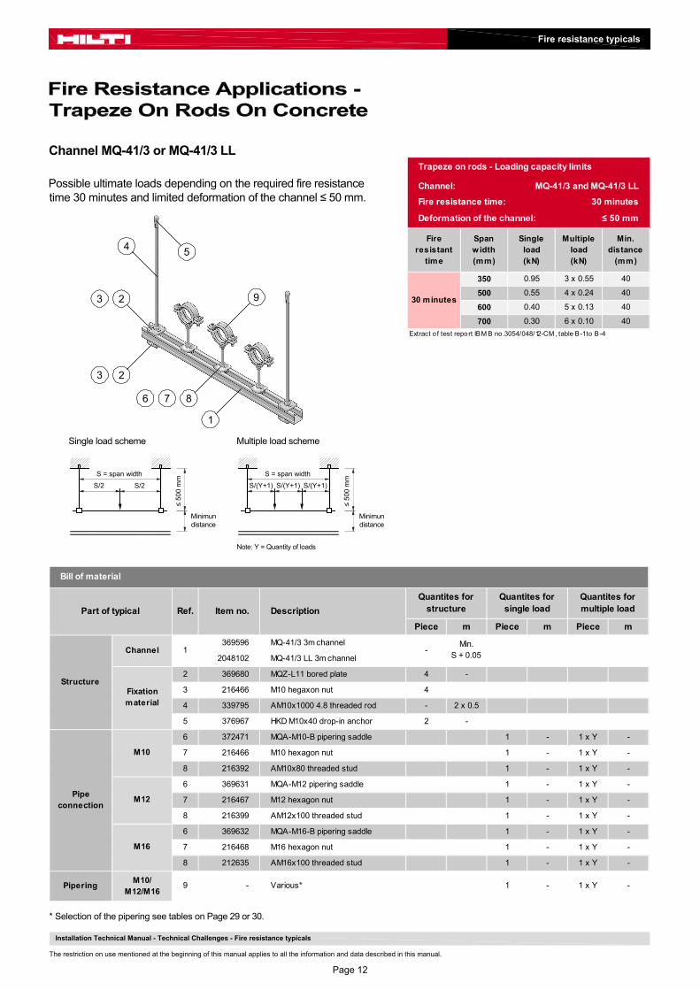
Possible ultimate loads depending on the required fire resistancetime 30 minutes and limited deformation of the channel ≤ 50 mm.
Channel MQ-41/3 or MQ-41/3 LL
Fire resistance typicals
* Selection of the pipering see tables on Page 29 or 30.
Installation Technical Manual - Technical Challenges - Fire resistance typicals
The restriction on use mentioned at the beginning of this manual applies to all the information and data described in this manual.
1
2
7
S/2
S = span width
S/2
Single load scheme
Minimundistance
≤ 5
00
mm
S/(Y+1)
S = span width
S/(Y+1) S/(Y+1)
Multiple load scheme
Note: Y = Quantity of loads
Minimundistance
≤ 5
00
mm
Trapeze on rods - Loading capacity limits
Channel: MQ-41/3 and MQ-41/3 LL
Fire resistance time: 30 minutes
Deformation of the channel: ≤ 50 mm
Fire resistant
time
Span width (mm)
Single load (kN)
Multiple load (kN)
Min. distance
(mm)
350 0.95 3 x 0.55 40
500 0.55 4 x 0.24 40
600 0.40 5 x 0.13 40
700 0.30 6 x 0.10 40
Extract o f test report IBM B no.3054/048/12-CM , table B-1 to B-4
30 minutes
Piece m Piece m Piece m
369596 MQ-41/3 3m channel
2048102 MQ-41/3 LL 3m channel
2 369680 MQZ-L11 bored plate 4 -
3 216466 M10 hegaxon nut 4
4 339795 AM10x1000 4.8 threaded rod - 2 x 0.5
5 376967 HKD M10x40 drop-in anchor 2 -
6 372471 MQA-M10-B pipering saddle 1 - 1 x Y -
7 216466 M10 hexagon nut 1 - 1 x Y -
8 216392 AM10x80 threaded stud 1 - 1 x Y -
6 369631 MQA-M12 pipering saddle 1 - 1 x Y -
7 216467 M12 hexagon nut 1 - 1 x Y -
8 216399 AM12x100 threaded stud 1 - 1 x Y -
6 369632 MQA-M16-B pipering saddle 1 - 1 x Y -
7 216468 M16 hexagon nut 1 - 1 x Y -
8 212635 AM16x100 threaded stud 1 - 1 x Y -
PiperingM10/
M12/M169 - Various* 1 - 1 x Y -
1 -Min.
S + 0.05
Fixation material
Bill of material
Part of typical Ref. Item no. Description
Quantites for structure
Quantites forsingle load
Quantites for multiple load
Pipeconnection
M10
M12
M16
Structure
Channel
3
23
86
4 5
9
Page 12

Possible ultimate loads depending on the required fireresistance time.
Vertical channel MQ-41/3 and horizontal channel MQ-41 D
Fire resistance typicals
* Selection of the pipering see tables on Page 29 or 30.
Installation Technical Manual - Technical Challenges - Fire resistance typicals
The restriction on use mentioned at the beginning of this manual applies to all the information and data described in this manual.
1
2
S/2
S = span width
S/2
Single load scheme
Minimumdistance
≤ 6
00
mm
10
S/(Y+1)
S = span width
S/(Y+1) S/(Y+1)
Multiple load scheme
Note: Y = Quantity of loads
Minimumdistance
≤ 6
00
mm
35
45
6
97 8
Piece m Piece m Piece m
1 369603 MQ-41 D 3m channel - S
2 369596 MQ-41/3 3m channel - 2 x 0.6
3 369665 MQW-S/2 angle 2 -
4 369651 MQP-21-72 base plate 2 -
5 369623 MQN pushbutton 12 -
6 2105718 HST3 M12x105 30/10 stud anchor 4 -
7 372471 MQA-M10-B pipering saddle 1 - 1 x Y -
8 216466 M10 hexagon nut 1 - 1 x Y -
9 216392 AM10x80 threaded stud 1 - 1 x Y -
7 369631 MQA-M12 pipering saddle 1 - 1 x Y -
8 216467 M12 hexagon nut 1 - 1 x Y -
9 216399 AM12x100 threaded stud 1 - 1 x Y -
7 369632 MQA-M16-B pipering saddle 1 - 1 x Y -
8 216468 M16 hexagon nut 1 - 1 x Y -
9 212635 AM16x100 threaded stud 1 - 1 x Y -
PiperingM10/
M12/M1610 - Various* 1 - 1 x Y -
Pipeconnection
M10
M12
M16
Structure
Channel
Fixation material
Bill of material
Part of typical Ref. Item no. Description
Quantites for structure
Quantites forsingle load
Quantites for multiple load
Trapeze on Frame - Loading capacity limits
Channel: Horizontal MQ-41 D and vertical MQ-41/3
Fire resistance time: 30, 60, 90, 120 minutes
Load (kN)
Min. distance
(mm)
Load (kN)
Min. distance
(mm)
700 2.54 284 6 x 0.64 50
1000 2.46 424 9 x 0.32 124
1250 1.98 458 11 x 0.24 139
700 1.48 239 6 x 0.45 90
1000 1.17 234 9 x 0.19 103
1250 1.00 470 11 x 0.12 97
700 1.09 148 6 x 0.32 110
1000 0.76 266 9 x 0.14 116
1250 0.67 355 11 x 0.08 136
700 0.87 161 6 x 0.25 84
1000 0.56 127 9 x 0.11 122
1250 0.51 394 11 x 0.06 205
Single load Multiple load
Extract o f test report IBM B no.3022/9626-CM , table A-1 to A-4
Span w idth (mm)
30 minutes
60 minutes
90 minutes
120 minutes
Fire resistant
time
Page 13

Possible ultimate loads depending on the required fireresistance time 30 minutes and limited deformation of thechannel ≤ 50 mm.
Vertical channel MQ-41/3 and horizontal channel MQ-41 D
Fire resistance typicals
* Selection of the pipering see tables on Page 29 or 30.
Installation Technical Manual - Technical Challenges - Fire resistance typicals
The restriction on use mentioned at the beginning of this manual applies to all the information and data described in this manual.
1
2
S/2
S = span width
S/2
Single load scheme
≤ 6
00
mm
10
S/(Y+1)
S = span width
S/(Y+1) S/(Y+1)
Multiple load scheme
Note: Y = Quantity of loads
≤ 6
00
mm
35
45
6
97 8
Piece m Piece m Piece m
1 369603 MQ-41 D 3m channel - S
2 369596 MQ-41/3 3m channel - 2 x 0.6
3 369665 MQW-S/2 angle 2 -
4 369651 MQP-21-72 base plate 2 -
5 369623 MQN pushbutton 12 -
6 2105718 HST3 M12x105 30/10 stud anchor 4 -
7 372471 MQA-M10-B pipering saddle 1 - 1 x Y -
8 216466 M10 hexagon nut 1 - 1 x Y -
9 216392 AM10x80 threaded stud 1 - 1 x Y -
7 369631 MQA-M12 pipering saddle 1 - 1 x Y -
8 216467 M12 hexagon nut 1 - 1 x Y -
9 216399 AM12x100 threaded stud 1 - 1 x Y -
7 369632 MQA-M16-B pipering saddle 1 - 1 x Y -
8 216468 M16 hexagon nut 1 - 1 x Y -
9 212635 AM16x100 threaded stud 1 - 1 x Y -
PiperingM10/
M12/M1610 - Various* 1 - 1 x Y -
Bill of material
Part of typical Ref. Item no. Description
Quantites for structure
Quantites forsingle load
Quantites for multiple load
Structure
Channel
Fixation material
Pipeconnection
M10
M12
M16
Distance≥ 50mm
Distance≥ 50mm
Trapeze on Frame - Loading capacity limits
Channel: Horizontal MQ-41 D and vertical MQ-41/3
Fire resistance time: 30 minutes
Deformation of the channel: ≤ 50 mm
Fire resistant time
Span width (mm)
Single load(kN)
Multiple load(kN)
700 1.20 6 x 0.64
1000 0.60 9 x 0.15
1250 0.30 11 x 0.07
30 minutes
Extract o f test report IBM B no.3022/9626-CM , table A-5
Page 14
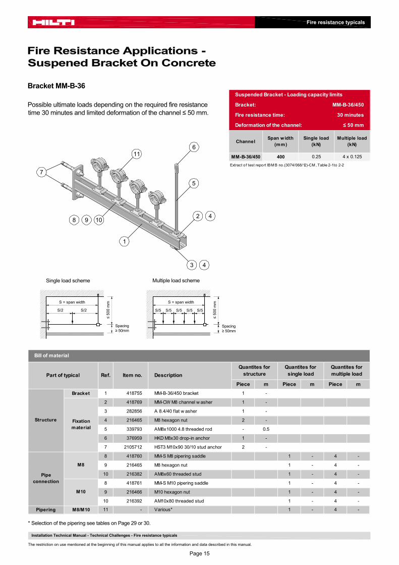
Possible ultimate loads depending on the required fire resistancetime 30 minutes and limited deformation of the channel ≤ 50 mm.
Bracket MM-B-36
Fire resistance typicals
* Selection of the pipering see tables on Page 29 or 30.
Installation Technical Manual - Technical Challenges - Fire resistance typicals
The restriction on use mentioned at the beginning of this manual applies to all the information and data described in this manual.
1
2
3
4
4
8
Multiple load scheme
Spacing≥ 50mm
≤ 5
00
mm
S/5
S = span width
S/5 S/5 S/5 S/5
Single load scheme
Spacing≥ 50mm
≤ 5
00
mmS = span width
S/2 S/2
Piece m Piece m Piece m
Bracket 1 418755 MM-B-36/450 bracket 1 -
2 418769 MM-CW M8 channel w asher 1 -
3 282856 A 8.4/40 f lat w asher 1 -
4 216465 M8 hexagon nut 2 -
5 339793 AM8x1000 4.8 threaded rod - 0.5
6 376959 HKD M8x30 drop-in anchor 1 -
7 2105712 HST3 M10x90 30/10 stud anchor 2 -
8 418760 MM-S M8 pipering saddle 1 - 4 -
9 216465 M8 hexagon nut 1 - 4 -
10 216382 AM8x60 threaded stud 1 - 4 -
8 418761 MM-S M10 pipering saddle 1 - 4 -
9 216466 M10 hexagon nut 1 - 4 -
10 216392 AM10x80 threaded stud 1 - 4 -
Pipering M8/M10 11 - Various* 1 - 4 -
Fixationmaterial
Pipeconnection
M8
M10
Structure
Bill of material
Part of typical Ref. Item no. Description
Quantites for structure
Quantites forsingle load
Quantites for multiple load
9 10
7
11
5
6
Suspended Bracket - Loading capacity limits
Bracket: MM-B-36/450
Fire resistance time: 30 minutes
Deformation of the channel: ≤ 50 mm
ChannelSpan w idth
(mm)Single load
(kN)Multiple load
(kN)
MM-B-36/450 400 0.25 4 x 0.125
Extract of test report IBM B no.(3074/068/12)-CM , Table 2-1 to 2-2
Page 15

Possible ultimate loads depending on the required fire resistancetime 30 minutes and limited deformation of the channel ≤ 50 mm.
Bracket MQK-41
Fire resistance typicals
* Selection of the pipering see tables on Page 29 or 30.
Installation Technical Manual - Technical Challenges - Fire resistance typicals
The restriction on use mentioned at the beginning of this manual applies to all the information and data described in this manual.
1
987
6
10
Multiple load scheme
Distance≥ 50mm
≤ 5
00
mm
S/4
S = span width
S/4 S/4 S/4
Single load scheme
Distance≥ 50mm
≤ 5
00
mmS = span width
S/2 S/2
23
2 3
4
5
Suspended Bracket - Loading capacity limits
Bracket: MQK-41
Fire resistance time: 30 minutes
Deformation of the channel: ≤ 50 mm
Piperingsaddle
Span w idth (mm)
Single load (kN)
Multiple load (kN)
350 0.40 3 x 0.30
500 0.30 3 x 0.20
600 0.20 3 x 0.12
350 0.50 3 x 0.35
500 0.40 3 x 0.25
600 0.30 3 x 0.15
≥ MQA-M8
≥ MQA-M10B
Extract of test report IBM B no.2100/580/15-CM , table 3-1
Piece m Piece m Piece m
369610 MQK-41/450 bracket
369611 MQK-41/600 bracket
2 369680 MQZ-L11 bored plate 2 -
3 216466 M10 hegaxon nut 2 -
4 339795 AM10x1000 4.8 threaded rod - 1 x 0.5
5 376967 HKD M10x40 drop-in anchor 1 -
6 2105718 HST3 M12x105 30/10 stud anchor 2 -
7 369629 MQA-M8 pipering saddle 1 - 3 -
8 216465 M8 hexagon nut 1 - 3 -
9 216382 AM8x60 threaded stud 1 - 3 -
7 372471 MQA-M10-B pipering saddle 1 - 3 -
8 216466 M10 hexagon nut 1 - 3 -
9 216392 AM10x80 threaded stud 1 - 3 -
7 369631 MQA-M12 pipering saddle 1 - 3 -
8 216467 M12 hexagon nut 1 - 3 -
9 216399 AM12x100 threaded stud 1 - 3 -
PiperingM8/
M10/M1210 - Various* 1 - 3 -
Pipeconnection
M8
M10
M12
Structure
Bracket 1 1 -
Fixation material
Bill of material
Part of typical Ref. Item no. Description
Quantites for structure
Quantites forsingle load
Quantites for multiple load
Page 16

Possible ultimate loads depending on the required fireresistance time.
Bracket MQK-41/3
Fire resistance typicals
* Selection of the pipering see tables on Page 29 or 30.
Installation Technical Manual - Technical Challenges - Fire resistance typicals
The restriction on use mentioned at the beginning of this manual applies to all the information and data described in this manual.
Multiple load scheme
Note: Y = Quantity of loads
Minimumdistance
≤ 5
00
mmS = span width
Single load scheme
MInimumdistance
≤ 5
00
mmS = span width
S/2 S/2
1
987
6
10
23
2 3
4
5
S/(Y+1) S/(Y+1) S/(Y+1) S/(Y+1)
Suspended Bracket - Loading capacity limits
Bracket: MQK-41/3
Fire resistance time: 30, 60, 90, 120 minutes
Fire resistant time
Span width (mm)
Single load (kN)
Multiple load (kN)
Min. distance
(mm)
350 1.70 3 x 1.06 185
500 1.70 4 x 0.76 270
600 1.70 5 x 0.59 325
350 1.20 3 x 0.58 170
500 1.20 4 x 0.40 230
600 1.20 5 x 0.31 270
350 0.80 3 x 0.40 155
500 0.80 4 x 0.28 270
600 0.80 5 x 0.21 260
350 0.60 3 x 0.31 175
500 0.60 4 x 0.22 230
600 0.60 5 x 0.16 260
120 minutes
Extract of test report IBM B no.3054/048/12-CM , Table C-1 to C-5
30 minutes
60 minutes
90 minutes
Piece m Piece m Piece m
370596 MQK-41/3/450 bracket
370597 MQK-41/3/600 bracket
2 369680 MQZ-L13 bored plate 2 -
3 216467 M12 hegaxon nut 2 -
4 339797 AM12x1000 4.8 threaded rod - 1 x 0.5
5 378544 HKD M12x50 drop-in anchor 1 -
6 2105718 HST3 M12x105 30/10 stud anchor 2 -
7 372471 MQA-M10-B pipering saddle 1 - 1 x Y -
8 216466 M10 hexagon nut 1 - 1 x Y -
9 216392 AM10x80 threaded stud 1 - 1 x Y -
7 369631 MQA-M12 pipering saddle 1 - 1 x Y -
8 216467 M12 hexagon nut 1 - 1 x Y -
9 216399 AM12x100 threaded stud 1 - 1 x Y -
7 369632 MQA-M16-B pipering saddle 1 - 1 x Y -
8 216468 M16 hexagon nut 1 - 1 x Y -
9 212635 AM16x100 threaded stud 1 - 1 x Y -
PiperingM10/
M12/M1610 - Various* 1 - 1 x Y -
Pipeconnection
M10
M12
M16
Bracket 1 1 -
Bill of material
Part of typical Ref. Item no. Description
Quantites for structure
Quantites forsingle load
Quantites for multiple load
StructureFixation material
Page 17
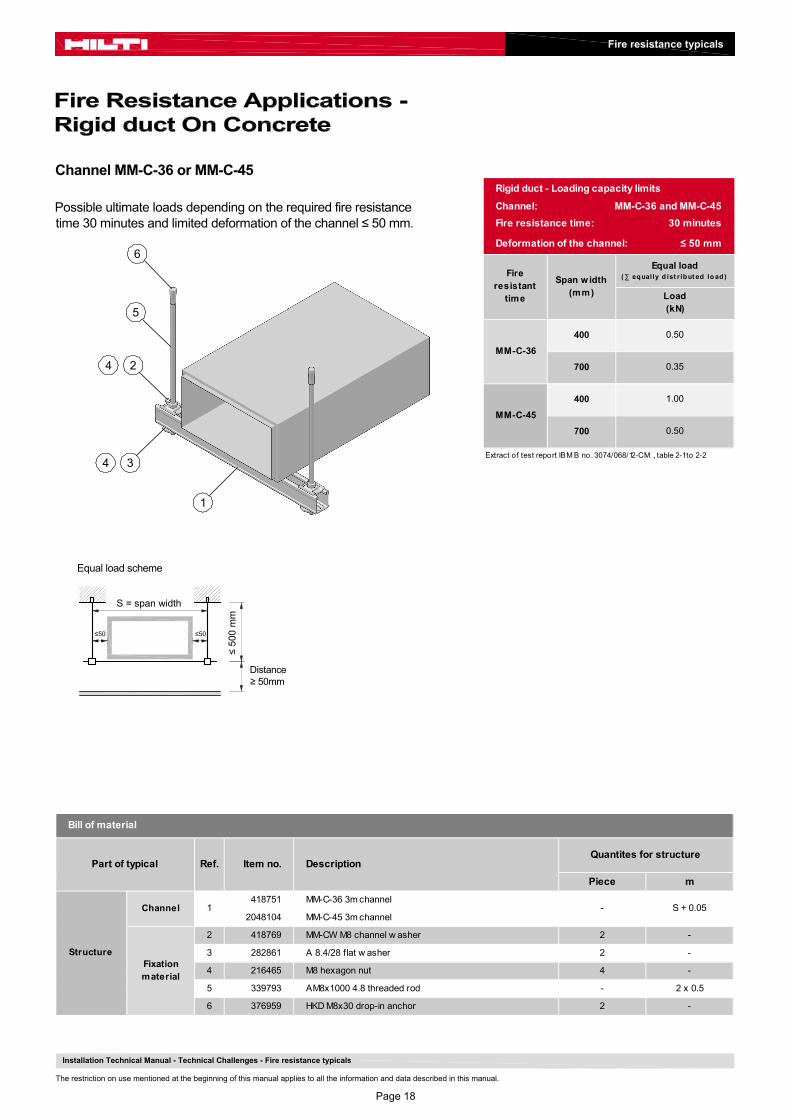
Possible ultimate loads depending on the required fire resistancetime 30 minutes and limited deformation of the channel ≤ 50 mm.
Channel MM-C-36 or MM-C-45
Fire resistance typicals
Installation Technical Manual - Technical Challenges - Fire resistance typicals
The restriction on use mentioned at the beginning of this manual applies to all the information and data described in this manual.
1
2
3
4
4
6
5
S = span width
Equal load scheme
Distance≥ 50mm
≤ 5
00 m
m
Rigid duct - Loading capacity limits
Channel: MM-C-36 and MM-C-45
Fire resistance time: 30 minutes
Deformation of the channel: ≤ 50 mm
Equal load(∑ equally d ist r ibut ed lo ad )Fire
resistant time
Span w idth (mm)
MM-C-36
MM-C-45
Load (kN)
700
400
700
400
0.50
1.00
0.35
0.50
Extract of test report IBM B no. 3074/068/12-CM , table 2-1 to 2-2
≤50 ≤50
Piece m
418751 MM-C-36 3m channel
2048104 MM-C-45 3m channel
2 418769 MM-CW M8 channel w asher 2 -
3 282861 A 8.4/28 flat w asher 2 -
4 216465 M8 hexagon nut 4 -
5 339793 AM8x1000 4.8 threaded rod - 2 x 0.5
6 376959 HKD M8x30 drop-in anchor 2 -
DescriptionQuantites for structure
Bill of material
Structure
Channel
Fixation material
1 - S + 0.05
Part of typical Ref. Item no.
Page 18

Possible ultimate loads depending on the required fireresistance time.
Channel MQ-41 or MQ-41 LL
Fire resistance typicals
Installation Technical Manual - Technical Challenges - Fire resistance typicals
The restriction on use mentioned at the beginning of this manual applies to all the information and data described in this manual.
1
23
23
4
5
S = span width
Equal load scheme
Minimumdistance
≤ 10
00
mm
Piece m
369591 MQ-41 3m channel
2048100 MQ-41 LL 3m channel
2 369680 MQZ-L11 bored plate 4 -
3 216466 M10 hegaxon nut 4 -
4 339795 AM10x1000 4.8 threaded rod - 2 x 1
5 376967 HKD M10x40 drop-in anchor 2 -
Structure
Channel 1 -Min.
S + 0.05
Fixation material
Bill of material
Part of typical Ref. Item no. DescriptionQuantites for structure
Rigid duct - Loading capacity limits
Channel: MQ-41 and MQ-41 LL
Fire resistance time: 30, 60, 90 minutes
Load (kN)
Min. distance
(mm)
1.3
1.7
≤ 12
50m
m
100
65
50
105
65
50
1.3
1.0
1.0
1.3
80
Extract o f test report IBM B no. 3054/048/12-CM , table D-26 to D-27
90 minutes
Equal load(∑ eq ually d ist r ib ut ed lo ad )
2.4
1.7
Fire resistant
time
Span w idth (mm)
110
30 minutes
60 minutes
≤50 ≤50
Page 19

Possible ultimate loads depending on the required fireresistance time.
Channel MQ-41/3 or MQ-41/3 LL
Fire resistance typicals
Installation Technical Manual - Technical Challenges - Fire resistance typicals
The restriction on use mentioned at the beginning of this manual applies to all the information and data described in this manual.
1
23
23
4
5
S = span width
Equal load scheme
Minimumdistance
≤ 10
00
mm
≤50 ≤50
Rigid duct - Loading capacity limits
Channel: MQ-41/3 and MQ-41/3 LL
Fire resistance time: 30, 60, 90 minutes
100
1.9 65
1.4 50
1.1 80
30 minutes
≤ 12
50 m
m
3.2
65
1.1 50
90 minutes1.4
60 minutes
1.9 105
1.4
110
Fire resistant
time
Span width (mm)
Equal load(∑ eq ually d ist r ib ut ed lo ad )
Load (kN)
Min. distance
(mm)
Extract o f test report IBM B no. 3054/048/12-CM , table D-26
Piece m
369596 MQ-41/3 3m channel
2048102 MQ-41/3 LL 3m channel
2 369680 MQZ-L13 bored plate 4 -
3 216467 M12 hegaxon nut 4 -
4 339797 AM12x1000 4.8 threaded rod - 2 x 1.0
5 378544 HKD M12x50 drop-in anchor 2 -
Bill of material
Part of typical Ref. Item no. DescriptionQuantites for structure
Structure
Channel 1 -Min.
S + 0.05
Fixation material
Page 20

Possible ultimate loads depending on the required fire resistancetime 30 minutes and limited deformation of the channel ≤ 50 mm.
Bracket MM-B-36
Fire resistance typicals
Installation Technical Manual - Technical Challenges - Fire resistance typicals
The restriction on use mentioned at the beginning of this manual applies to all the information and data described in this manual.
1
2
3
4
7 5
6
Equal load scheme
Distance≥ 50mm
≤ 5
00 m
m
S = span width
≤50 ≤50
4
Piece m
Bracket 1 418755 MM-B-36/450 bracket 1 -
2 418769 MM-CW M8 channel w asher 1 -
3 282856 A 8.4/40 f lat w asher 1 -
4 216465 M8 hexagon nut 2
5 339793 AM8x1000 4.8 threaded rod - 0.5
6 376959 HKD M8x30 drop-in anchor 1 -
7 2105712 HST3 M10x90 30/10 stud anchor 2 -
Structure Fixationmaterial
Bill of material
Part of typical Ref. Item no. DescriptionQuantites for structure
Rigid duct - Loading capacity limits
Bracket: MM-B-36
Fire resistance time: 30 minutes
Deformation of the channel: ≤ 50 mm
Span w idth (mm)
Equal load(∑ equally d ist r ibut ed lo ad )
Load (kN)
MM-B-36 400 0.5
Channel:
Extract o f test report IBM B no. 3074/068/12-CM , table 2-1 to 2-2
Page 21

Possible ultimate loads depending on the required fireresistance time.
Bracket MQK-41 or MQK-41/3
Fire resistance typicals
Installation Technical Manual - Technical Challenges - Fire resistance typicals
The restriction on use mentioned at the beginning of this manual applies to all the information and data described in this manual.
1
6
23
2 3
4
5
Equal load scheme
Minimumdistance
≤ 10
00
mmS = span width
≤50 ≤50
Rigid duct - Loading capacity limits
Bracket: MQK-41 and MQK-41/3
Fire resistance time: 30, 60, 90 minutes
MQK-41/600
MQK-41/3/600
MQK-41/600
MQK-41/3/600
2.4 3.2
1.7 1.9
1.3 1.4
1.7 1.9
1.3 1.4
1.0 1.1
1.3 1.4
1.0 1.1
65
50
90 minutes
Fire resistant
time
Span width (mm)
Equal load (∑ eq ually d ist r ib ut ed lo ad)
Load (kN)
Min. distance (mm)
110
80
30 minutes
600
mm
100
65
50
60 minutes
105
Extract o f test report IBM B no. 3054/048/12-CM , table D-26 to D-27
Piece m
369611 MQK-41/600 bracket
370597 MQK-41/3/600 bracket
2 369680 MQZ-L13 bored plate 2 -
3 216467 M12 hegaxon nut 2 -
4 339797 AM12x1000 4.8 threaded rod - 1
5 378544 HKD M12x50 drop-in anchor 1 -
6 2105718 HST3 M12x105 30/10 stud anchor 2 -
Bill of material
Part of typical Ref. Item no. DescriptionQuantites for structure
Bracket 1 1 -
StructureFixation material
Page 22

Possible ultimate loads depending on the required fire resistancetime 30 minutes and limited deformation of the channel ≤ 50 mm.
Channel MM-C-36 or MM-C-45
Fire resistance typicals
Installation Technical Manual - Technical Challenges - Fire resistance typicals
The restriction on use mentioned at the beginning of this manual applies to all the information and data described in this manual.
1
2
3
4
4
6
5
S = span width
Equal load scheme
Distance≥ 50mm
≤ 5
00 m
m
≤50 ≤50
Flexible duct - Loading capacity limits
Channel: MM-C-36 and MM-C-45
Fire resistance time: 30 minutes
Deformation of the channel: ≤ 50 mm
MM-C-45400 1.00
700 0.50
Channel:Span w idth
(mm)
Equal load(∑ eq ually d ist r ib ut ed lo ad )
Load (kN)
MM-C-36400 0.50
700 0.35
Extract o f test report IBM B no. 3074/068/12-CM , table 2-1 to 2-2
Piece m
418751 MM-C-36 3m channel
2048104 MM-C-45 3m channel
2 418769 MM-CW M8 channel w asher 2 -
3 282861 A 8.4/28 flat w asher 2 -
4 216465 M8 hexagon nut 4 -
5 339793 AM8x1000 4.8 threaded rod - 2 x 0.5
6 376959 HKD M8x30 drop-in anchor 2 -
Bill of material
Part of typical Ref. Item no. DescriptionQuantites for structure
Structure
Channel 1 - S + 0.05
Fixation material
Page 23

Possible ultimate loads depending on the required fireresistance time.
Channel MQ-41 or MQ-41 LL
Fire resistance typicals
Installation Technical Manual - Technical Challenges - Fire resistance typicals
The restriction on use mentioned at the beginning of this manual applies to all the information and data described in this manual.
1
23
23
4
5
S = span width
Equal load scheme
≤ 10
00
mm
≤50 ≤50
Flexible duct - Loading capacity limits
Channel: MQ-41 and MQ-41 LL
Fire resistance time: 30, 60, 90 minutes
Fire resistant time
Span w idth (mm)
1.30
1.0090 minutes
60 minutes
Extract o f test report IBM B no. 3054/048/12-CM , table D-27
Equal load(∑ eq ually d ist r ibut ed
load )
30 minutes
≤ 12
50m
m
Load (kN)
2.40
1.70
1.30
1.70
1.30
1.00
Piece m
369591 MQ-41 3m channel
2048100 MQ-41 LL 3m channel
2 369680 MQZ-L11 bored plate 4 -
3 216466 M10 hegaxon nut 4 -
4 339795 AM10x1000 4.8 threaded rod - 2 x 1
5 376967 HKD M10x40 drop-in anchor 2 -
Structure
Channel 1 -Min.
S + 0.05
Fixation material
Bill of material
Part of typical Ref. Item no. DescriptionQuantites for structure
Page 24

Possible ultimate loads depending on the required fireresistance time.
Channel MQ-41/3 or MQ-41/3 LL
Fire resistance typicals
Installation Technical Manual - Technical Challenges - Fire resistance typicals
The restriction on use mentioned at the beginning of this manual applies to all the information and data described in this manual.
1
23
23
4
5
S = span width
Equal load scheme
≤ 10
00
mm
≤50 ≤50
Piece m
369596 MQ-41/3 3m channel
2048102 MQ-41/3 LL 3m channel
2 369680 MQZ-L13 bored plate 4 -
3 216467 M12 hegaxon nut 4 -
4 339797 AM12x1000 4.8 threaded rod - 2 x 1.0
5 378544 HKD M12x50 drop-in anchor 2 -
Bill of material
Part of typical Ref. Item no. DescriptionQuantites for structure
Structure
Channel 1 -Min.
S + 0.05
Fixation material
Flexible duct - Loading capacity limits
Channel: MQ-41/3 and MQ-41/3 LL
Fire resistance time: 30, 60, 90, 120 minutes
≤ 350
≤ 700
≤ 1000
≤ 1250
≤ 350
≤ 700
≤ 1000
≤ 1250
≤ 350
≤ 700
≤ 1000
≤ 1250
≤ 350
≤ 700
≤ 1000
≤ 1250
Extract of test report IBM B no. 3054/048/12-CM , table D-6 to D-9
2.65
2.50
Fire resistant time
2.10
1.60
1.35
1.25
1.20
0.85
0.70
0.65
60 minutes
Span w idth (mm)
Equal load(∑ eq ually d ist r ibut ed
load )
30 minutes
Load (kN)
3.40
3.00
90 minutes
120 minutes
1.50
1.10
0.95
0.85
Page 25

Possible ultimate loads depending on the required fire resistancetime 30 minutes and limited deformation of the channel ≤ 50 mm.
Bracket MM-B-36
Fire resistance typicals
Installation Technical Manual - Technical Challenges - Fire resistance typicals
The restriction on use mentioned at the beginning of this manual applies to all the information and data described in this manual.
1
2
3
4
7
5
6
Equal load scheme
Distance≥ 50mm
≤ 5
00 m
m
S = span width
≤50 ≤50
Flexible duct - Loading capacity limits
Bracket: MM-B-36Fire resistance time: 30 minutes
Deformation of the channel: ≤ 50 mm
Extract o f test report IBM B no. 3074/068/12-CM , table 2-1 to 2-2
MM-B-36
Equal load(∑ equally d ist r ibut ed lo ad )
Load (kN)
Span w idth (mm)
Bracket:
400 0.5
4
Piece m
Bracket 1 418755 MM-B-36/450 bracket 1 -
2 418769 MM-CW M8 channel w asher 1 -
3 282856 A 8.4/40 f lat w asher 1 -
4 216465 M8 hexagon nut 2
5 339793 AM8x1000 4.8 threaded rod - 0.5
6 376959 HKD M8x30 drop-in anchor 1 -
7 2105712 HST3 M10x90 30/10 stud anchor 2 -
Structure Fixationmaterial
Bill of material
Part of typical Ref. Item no. DescriptionQuantites for structure
Page 26

Possible ultimate loads depending on the required fireresistance time.
Bracket MQK-41 or MQK-41/3
Fire resistance typicals
Installation Technical Manual - Technical Challenges - Fire resistance typicals
The restriction on use mentioned at the beginning of this manual applies to all the information and data described in this manual.
1
6
23
2 3
4
5
Equal load scheme
≤ 10
00
mmS = span width
≤50 ≤50
Flexible duct - Loading capacity limits
Bracket: MQK-41 and MQK-41/3
Fire resistance time: 30, 60, 90 minutes
350
500
600
350
500
600
350
500
600
350
500
600
Span width (mm)
Equal load(∑ eq ually d ist r ib ut ed
lo ad )
30 minutes
120 minutes
60 minutes
Fire resistant
time
Extract o f test report IBM B no.3054/048/12-CM
90 minutes
1.70
Load (kN)
3.40
3.30
3.15
1.50
1.30
1.15
MQK-41 or MQK-41/3
2.10
1.80
1.70
2.10
1.80
Piece m
369610 MQK-41/450 bracket
369611 MQK-41/600 bracket
370596 MQK-41/3/450 bracket
370597 MQK-41/3/600 bracket
2 369680 MQZ-L13 bored plate 2 -
3 216467 M12 hegaxon nut 2
4 339797 AM12x1000 4.8 threaded rod - 1
5 378544 HKD M12x50 drop-in anchor 1 -
6 2105718 HST3 M12x105 30/10 stud anchor 2 -
-
Fixation material
Structure
Bill of material
Part of typical Ref. Item no. DescriptionQuantites for structure
Bracket 1 1
Page 27

Hilti has tested various types of pipe ring over the last few years in accordance with the RAL quality guidelineGZ-656 [6]. Furthermore, in the past other rings were fire-tested and evaluated by IBMB in Braunschweig. Thecorresponding RAL and IBMB test reports are summarized in annex 3.
Critical areas of suspended pipe rings when exposed to fire:
• Connection boss - Welded seam - Thread failure, internal thread on connection boss or threaded rod
• Closing mechanism - Joint - Screw - Quick-lock closure
Overview:
Fire resistance typicals
Installation Technical Manual - Technical Challenges - Fire resistance typicals
The restriction on use mentioned at the beginning of this manual applies to all the information and data described in this manual.
MPN-LI MPN-QRC MP-HI M8/M10 MPN-RC MP-MI/MISRAL TD656.2011-17a.01 IBMB (3364/7036)-CM RAL TD656.2011-18a.01 IBMB (3712/787/09)-CM RAL TD656.2013-04a.01
MP-MX/MXI MP-SRNI MP-SRN MPN-MR MP-MRXIIBMB (3365/7046)-CM RAL TD656.2011-16a.01 RAL TD656.2011-16a.02 IBMB (3366/7056)-CM IBMB (3366/7056)-CM
Page 28

Hilti fire-tested galvanized pipe rings
The following conditions must be clarified before a suitable pipe ring can be determinedbased upon the table:
1. The applicable pipe diameter.2. Calculation of pipe weight per meter, taking the filling and possible insulation into account.3. Definition of the available space between the pipe ring and relevant fire protection applications that are
positioned below.4. Clarification of the required fire resistance time.
The following table is used to clarify whether the pipe weight is lower than the maximumload capacity of the pipe ring with the specified spacing of the suspensions.Furthermore, it is possible to read whether the spacing is sufficient between the pipering and a classified building component or system that is installed below.
Fire resistance typicals
Installation Technical Manual - Technical Challenges - Fire resistance typicals
The restriction on use mentioned at the beginning of this manual applies to all the information and data described in this manual.
Load / Defl.
30 min
90 min
30 min
90 min
30 min
30 min
90 min
30 min
90 min
30 min
90 min
[mm][N]
/ [mm][N]
/ [mm][mm]
[N] / [mm]
[N] / [mm]
[mm][N]
/ [mm][mm]
[N] / [mm]
[N] / [mm]
[mm][N]
/ [mm][N]
/ [mm][mm]
[N] / [mm]
[N] / [mm]
368
457
2"
40 -
93 450
/ 50190 / 75
38 -
66
150 / 15 280 / 39
140 / 39
Pip
e S
ize
177.
8 -
244.
5
6" 386
97 -
168
390 / 30
1320 / 66
730 / 75
108
- 16
6 1600 / 50 1700 / 148
850 / 148
MP
-MX
/ M
P-M
XI
(M10
/M12
/M16
)
60 -
93
68 -
90
270 / 25 850 / 45
430 / 59
508
770 / 50 1780 / 69
790 / 78
163
- 50
8 2300 / 50 3000 / 218
1600 / 218
947
1600
2600
3200
8"
4"
99 -
118
500 / 50 750 / 82
360 / 82
99 -
170
(20
x 2
mm
)
1050 / 50 1700 / 122
850 / 122
72
3"
40 -
93
(2
0 x
1.5
mm
)
200 / 50
380 / > 50
66 -
110
280 / 30 580 / 46
230 / 46
209
5"
110
- 17
2 590 / 50 640 / 54
310 / 54
298
7
1"
MP
-MI
/ M
IS (
M10
/M12
/M16
)
14 -
64
230 / 20 840 / 39
350 / 54
8 -
38
50 / 10 270 / 27
90 / 30
300 / 50
130 / 55
MP
N-R
C (
M8/
M10
)
8 -
61 (
20 x
1 m
m)
100 / 50
130 / > 50
MP
-HI
(M8)
400 / 50
590 / > 50
41
135
Load / Deflection Max. weight
steel pipe, filled
[N/m]
8/11
MP
N-L
I (M
8)
8 -
61
120 / 10320 / 23
70 / 31
MP
N-Q
RC
(M
10)
8 -
41
Cla
mp
ing
R
an
ge
Cla
mp
ing
R
an
ge
Load / Deflection
Cla
mp
ing
R
an
ge
Load / Deflection
Cla
mp
ing
R
an
ge
Cla
mp
ing
R
an
ge
Load / Deflection
Cla
mp
ing
R
an
ge
Load / Deflection
Selection table for galvanized pipe rings
Note: Use fire-tested Hilti anchors (annex 7)
Page 29

Hilti fire-tested stainless steel pipe rings
The following conditions must be clarified before a suitable pipe ring can be determinedbased upon the table:
1. The applicable pipe diameter.2. Calculation of pipe weight per meter, taking the filling and possible insulation into account.3. Definition of the available space between the pipe ring and relevant fire protection applications that are
positioned below.4. Clarification of the required fire resistance time.
The following table is used to clarify whether the pipe weight is lower than the maximumload capacity of the pipe ring with the specified spacing of the suspensions.Furthermore, it is possible to read whether the spacing is sufficient between the pipering and a classified building component or system that is installed below.
Fire resistance typicals
Installation Technical Manual - Technical Challenges - Fire resistance typicals
The restriction on use mentioned at the beginning of this manual applies to all the information and data described in this manual.
30 min
90 min
30 min
90 min
[mm][N]
/ [mm][N]
/ [mm][mm]
[N] / [mm]
[N] / [mm]
457
508
368
MR
XI
(M16
)
244.
5 -
508 1500
/ 50 3600 / 128
1300 / 193
8"
4"
5"
3"
MP
-MR
(M
12/M
16)
68 -
219
.1 1500
/ 50 3600 / 128
1300 / 128
2"
42 -
60
1040 / 10 1600 / 12
700 / 17 42
- 6
0
1040 / 10 1600 / 12
6"
8/11
MP
-SR
NI
(M8/
M10
)
17 -
34
310 / 10 1300 / 20
410 / 41
MP
-SR
N (
M8/
M10
)
Cla
mp
ing
Ra
ng
e
Load / Deflection
Pip
e S
ize
Cla
mp
ing
Ra
ng
e
Load / Deflection
700 / 17
Note: Use fire-tested Hilti anchors (annex 7)
Ma
x. w
eig
ht o
f w
ate
r fil
led
st
ain
less
ste
el
pip
es
(DIN
EN
102
96/ D
IN E
N 1
0312
)
Selection table for stainless steel pipe rings
[N/m]
59
32
2
100
166
231
821
1377
2619
3224
338
21 -
42
310 / 10 1300 / 20
410 / 41
1"
Page 30

To avoid sudden failure of the upright pipe rings due to lack of rigidity, it is recommended that the threaded rodlengths specified in the following tables are not exceeded.Max. threaded rod length for upright installation of pipe rings .
Recommended maximum threaded rod length for upright installation of pipe rings :
Fire resistance typicals
Installation Technical Manual - Technical Challenges - Fire resistance typicals
The restriction on use mentioned at the beginning of this manual applies to all the information and data described in this manual.
30 min 60 min 90 min 120 min
100 80 80
150
200
250
300
400
450
500
30 min 60 min 90 min 120 min
100 140 140
150
200
250
300
400
450
500
600
700
750
30 min 60 min 90 min 120 min
100 160
150
200
250
300
400 80 60
450
500
600 40
700
750
800
900
1000
1050
1250
1300
1500
Threaded rod M10 (4.8)
60 40
80
12060
8040
160
160
120 80
120
60
40
40
160120
Threaded rod M12 (4.8)
Threaded rod M8 (4.8)
40
80
80
40
Length of rod [mm]
Vertical load [N]
40
40
Length of rod [mm]
Vertical load [N] Length of rod [mm]
Vertical load [N]
140
140
80 80
80
4040
80 40
30 min 60 min 90 min 120 min
400 160
450
500
600 120
700 140 100
750
800
900 100 60
1000 80 40
1050
1100
1200
1250
1300
1350
1400
1500
1600
1700
2000
2100
2250
2300
2500
2600
2900
60
10040
80
60
40
Threaded rod M16 (4.8)
160
160
160 140
120 80
140
120
14060
100
8040
120
Vertical load [N] Length of rod [mm]
Page 31

Cutting
To guarantee the loads recommended in this manual, there is an important cutting rule that has to be followed.The oblong holes must not be cut. It does not apply for round holes.
MM-C-36
MM-C-45
MQ-21
MQ-41 or MQ-41/3
MQ-41/3 LL or MQ-41/3 LL
Distance of the cut from the oblong hole edgeThere must be a minimum distance between the cut and oblong holes, see details below.
MM-C-36
MM-C-45
MQ-21
MQ-41 or MQ-41/3
MQ-41/3 LL or MQ-41/3 LL
Fire resistance typicals
Installation Technical Manual - Technical Challenges - Fire resistance typicals
The restriction on use mentioned at the beginning of this manual applies to all the information and data described in this manual.
Min. 5 mm
Min. 18 mm
Min. 18 mm
Min. 18 mm
Min. 18 mm
Min. 18 mm
Min. 18 mm
Min. 5 mm
Min. 5 mm
Min. 5 mm
Page 32

There is a list of used annexes:
Annex 1: Calculation of the deformation of installation channels exposed to fire – MFPA Leipzig GmbH
Annex 2: Fire protection design of installation systems – Process steps
Annex 3: IBMB and RAL test reports – Pipe rings
Annex 3a: IBMB test report – MPN-QRC
Annex 3b: IBMB test report – MPN-RC
Annex 3c: IBMB test report – MP-MX/MXI
Annex 3d: RAL test report – MPN-LI
Annex 3e: RAL test report – MP-HI
Annex 3f: RAL test report – MP-MI
Annex 3g: RAL test report – MP-SRN
Annex 3h: IBMB test report – MP-SRNI
Annex 4: IBMB test report – Roller connector
Annex 5: IBMB test reports – Installation channel systems
Annex 5a: IBMB test report – MM installation channel system
Annex 5b: IBMB test report – MQ-21 & MQ-41 installation channel system
Annex 5b: IBMB test report – MQ-41/3 installation channel system
Annex 5d: IBMB test report – U-support
Annex 6: Assessment - IBB, Germany Page
Anlage 7: Fire-tested Hilti anchors Page
Annex 7: Fastening Technology Manual for Building Construction and Engineering Construction, issue 08/2015
All these annexes are available in german in the " Installation Technical Manual - Technical Challenges - Fire
Resistance" and the english version are available on request. For support please contact your local Hilti expert.
Fire resistance typicals
Installation Technical Manual - Technical Challenges - Fire resistance typicals
The restriction on use mentioned at the beginning of this manual applies to all the information and data described in this manual.
Page 33

Hilti. Outperform. Outlast.
Hilti Corporation I 9494 Schaan I Liechtenstein I P +423 234 2111 I www.facebook.com/hiltigroup I www.hilti.com
Hilt
i = re
gist
ered
trad
emar
k of
Hilt
i Cor
p., S
chaa
n I I
ssue
d by
BU
Inst
alla
tion
Sys
tem
s V
ersi
on 1
.0 I
12.2
016
I © 2
016
I Rig
ht o
f tec
hnic
al a
nd p
rogr
amm
e ch
ange
s re
serv
ed S
. E. &
O.