Embed Size (px)
Citation preview
First characterizations of a Ring Cavityfor a colt atom gravimeter
Simon Schuster
University Tubingen
March 28, 2015

1 Calculation of beamparamters
1.1 Gerneral parameters
The in the experiment used ring cavity consists out of three high reflective mirrors, likeshown in figure 1.1.
Figure 1.1: Schematic grafic of the ring cavity. The light gets transimitted into the ring cavitythrough mirror 1, indicated by Ein. The beams path’s between mirror 1, 2 and 3are named P1 P2. Throug all three mirrors light gets transmitted out of the cavity.
Mirror 1 is planar, mirror 2 and 3 have a radius of curvature of r = 5 cm. Total lighttraveling length is L = P1 + P2/2 + P2/2 = 3.8 cm.
P1 and P2 form a right triangle, with it’s corner on mirror 1. Therefore is P1/2 = c =L/(√
2 + 2) and P2 = L/(√
2 + 1).
It’s free spectral range is ν0 = c/L = 7.889 GHz, where c is the speed of light. The mirrorsdo at the moment of the internship (January 2015) have reflectivities of R1 = 0.997and R2,3 = 0.999. After one circulation in the cavity the electric lightfield is becuse of
tranmission losses damped by the factor rd =√R1R2
2. The finesse F gives a value for thelosses of a resonator, which can be calculated out of the damping factor rd over
F = π
√rd
1− rd. (1.1)
For the given reflectiveties the finesse is F = 12561. The higher the finesse, the slower thelightfield in the cavity decayes. In a more developed state of the experiment the mirrors
1Source: ’Angewandte Optik und Laserphysik’, lecture of Prof. Claus Zimmerman, University Tubingen,2013
2

1.2. Gaussian parameters of the ring cavity 3
will be changed to one’s with higher reflectivities and a finesse of F ≈ 150000 will beneeded to reach.Figure 1.2 shows the resonators groundmode with modulated sidebands to measure it’sfinesse.
Figure 1.2: Modulated side band’s to measure linewith and finesse. The diode lasers laserdiode current was modulated with fmod = 20 MHz. The resonators full linewidth istherefore νFWHM = 4.92 MHz which corresponds to a finesse of F ≈ 1600.
1.2 Gaussian parameters of the ring cavity
A gaussian beam can be characterised with the confocal parameter z0. It’s value gives thedistance from the focal point of a gaussian beam to the point where the radius of cuvatureof the beams wavefronts is at it’s minimum, or the radius ω of the beam is ω =
√2ω0,
where ω0 is the beams waist diameter.z gives the position in a beam, relativ to the waist ω0. z and z0 are combined to the valueq = z + iz0.
2
The ray’s path throuh a optical system can be described with transfer matrices
M =
(A BC D
). (1.2)
Depending on the system the ray’s parameters are changed to
q2 =Aq1 +B
Cq1 +D, (1.3)
with the beams parameters q1 infront of a the optical system and q2 after it.
2Soruce: H. Kogelnik and T. Li, ”Laser Beams and Resonators,” Appl. Opt. 5, 1550-1567 (1966)
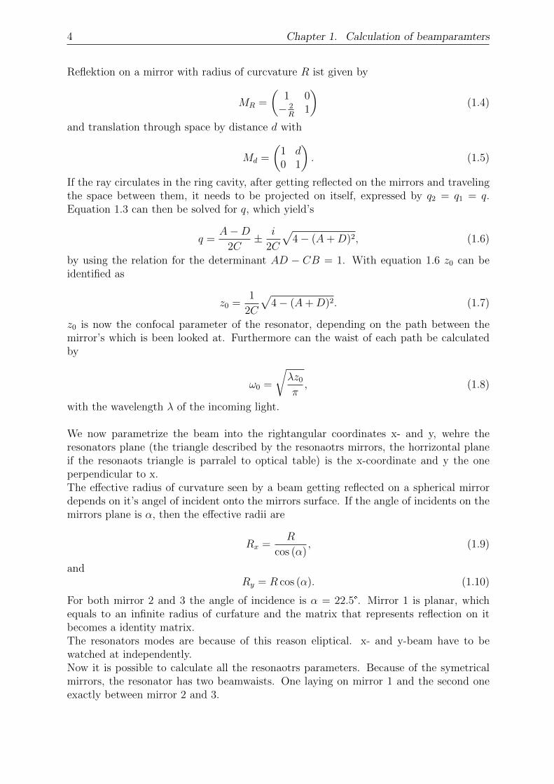
4 Chapter 1. Calculation of beamparamters
Reflektion on a mirror with radius of curcvature R ist given by
MR =
(1 0− 2
R1
)(1.4)
and translation through space by distance d with
Md =
(1 d0 1
). (1.5)
If the ray circulates in the ring cavity, after getting reflected on the mirrors and travelingthe space between them, it needs to be projected on itself, expressed by q2 = q1 = q.Equation 1.3 can then be solved for q, which yield’s
q =A−D
2C± i
2C
√4− (A+D)2, (1.6)
by using the relation for the determinant AD − CB = 1. With equation 1.6 z0 can beidentified as
z0 =1
2C
√4− (A+D)2. (1.7)
z0 is now the confocal parameter of the resonator, depending on the path between themirror’s which is been looked at. Furthermore can the waist of each path be calculatedby
ω0 =
√λz0π, (1.8)
with the wavelength λ of the incoming light.
We now parametrize the beam into the rightangular coordinates x- and y, wehre theresonators plane (the triangle described by the resonaotrs mirrors, the horrizontal planeif the resonaots triangle is parralel to optical table) is the x-coordinate and y the oneperpendicular to x.The effective radius of curvature seen by a beam getting reflected on a spherical mirrordepends on it’s angel of incident onto the mirrors surface. If the angle of incidents on themirrors plane is α, then the effective radii are
Rx =R
cos (α), (1.9)
andRy = R cos (α). (1.10)
For both mirror 2 and 3 the angle of incidence is α = 22.5°. Mirror 1 is planar, whichequals to an infinite radius of curfature and the matrix that represents reflection on itbecomes a identity matrix.The resonators modes are because of this reason eliptical. x- and y-beam have to bewatched at independently.Now it is possible to calculate all the resonaotrs parameters. Because of the symetricalmirrors, the resonator has two beamwaists. One laying on mirror 1 and the second oneexactly between mirror 2 and 3.
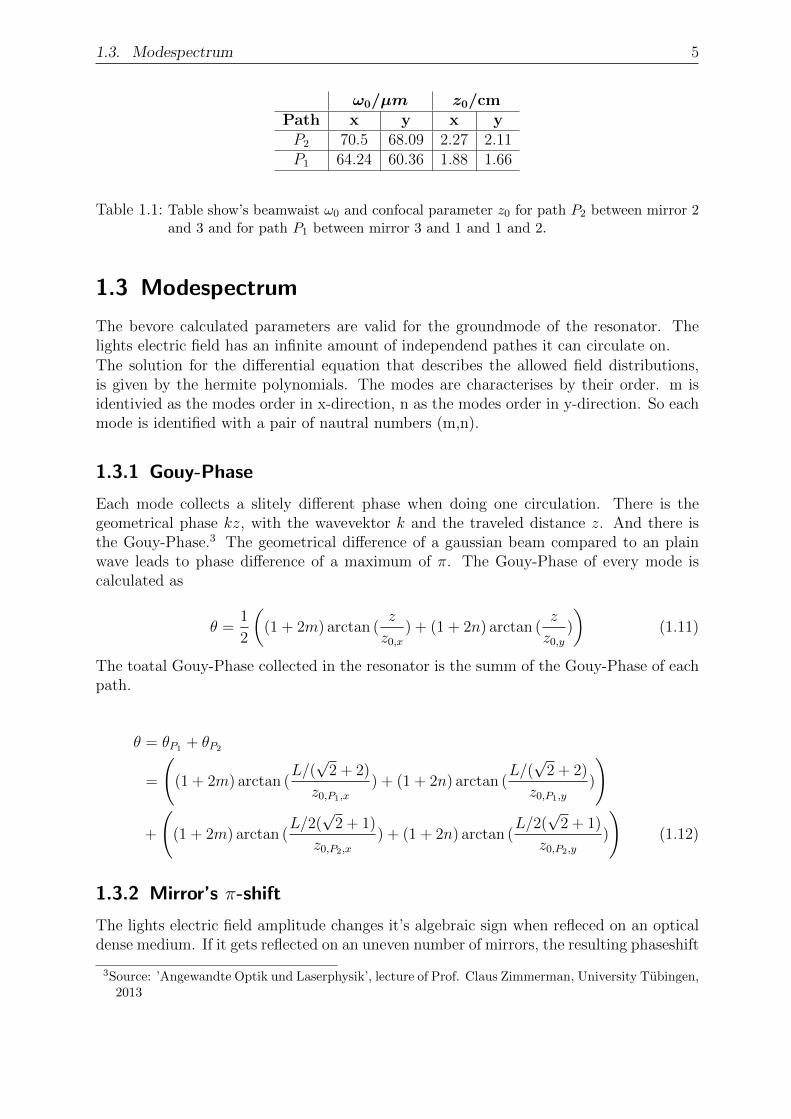
1.3. Modespectrum 5
ω0/µm z0/cmPath x y x yP2 70.5 68.09 2.27 2.11P1 64.24 60.36 1.88 1.66
Table 1.1: Table show’s beamwaist ω0 and confocal parameter z0 for path P2 between mirror 2and 3 and for path P1 between mirror 3 and 1 and 1 and 2.
1.3 Modespectrum
The bevore calculated parameters are valid for the groundmode of the resonator. Thelights electric field has an infinite amount of independend pathes it can circulate on.The solution for the differential equation that describes the allowed field distributions,is given by the hermite polynomials. The modes are characterises by their order. m isidentivied as the modes order in x-direction, n as the modes order in y-direction. So eachmode is identified with a pair of nautral numbers (m,n).
1.3.1 Gouy-Phase
Each mode collects a slitely different phase when doing one circulation. There is thegeometrical phase kz, with the wavevektor k and the traveled distance z. And there isthe Gouy-Phase.3 The geometrical difference of a gaussian beam compared to an plainwave leads to phase difference of a maximum of π. The Gouy-Phase of every mode iscalculated as
θ =1
2
((1 + 2m) arctan (
z
z0,x) + (1 + 2n) arctan (
z
z0,y)
)(1.11)
The toatal Gouy-Phase collected in the resonator is the summ of the Gouy-Phase of eachpath.
θ = θP1 + θP2
=
((1 + 2m) arctan (
L/(√
2 + 2)
z0,P1,x
) + (1 + 2n) arctan (L/(√
2 + 2)
z0,P1,y
)
)
+
((1 + 2m) arctan (
L/2(√
2 + 1)
z0,P2,x
) + (1 + 2n) arctan (L/2(
√2 + 1)
z0,P2,y
)
)(1.12)
1.3.2 Mirror’s π-shift
The lights electric field amplitude changes it’s algebraic sign when refleced on an opticaldense medium. If it gets reflected on an uneven number of mirrors, the resulting phaseshift
3Source: ’Angewandte Optik und Laserphysik’, lecture of Prof. Claus Zimmerman, University Tubingen,2013

6 Chapter 1. Calculation of beamparamters
is π. Only horizontal modes of uneven order are affected4. This geometric phaseshift canbe expressed by
ϕgeom =π
2(1− (−1)m). (1.13)
1.3.3 Resonace frequencies
Total phase after one circulation is then
ϕ = −kL+ θ(z) + ϕgeom = 2πq, (1.14)
with the total length L of the resonator. Because we are looking for the case of constructiveinterference, the total phase needs to be equal to 2πq, with q ∈ Z. Because of k = 2π/λand c = νλ, equation 1.14 can be solved for the resonance frequency ν of the resonaotorsmodes
νq,m,n =c
2πL(θ + ϕgeom − 2πq). (1.15)
4Hermite polynomes of uneven order are antisymmetric.

1.3. Modespectrum 7
Figure 1.3: Calculated spectrum of resonators modes. The pair of numbers in the bracket showthe modes orders. The number under the bracket show the like in eqaution 1.15calculated modes frequency.

8 Chapter 1. Calculation of beamparamters
1.3.4 s- and p-polarisation
The plane of incident onto the mirrors surface is the resonators triangle, or in this casethe laboratories optic table. Linear polarised light perpendicular to the plane of incidenceis called s-polarised5. It’s electric field amplitude vector is parallel to the mirrors plane.p-polarised lights electric field amplitude is parallel to the plane of incidence.The mirrors dielectric layers are designed, so that p-polarised light has a much higherreflectivity than s-polarised. Therefor by p-polarised light exited resonator modes arecalled high finesse modes. The ones exited by s-polarised light are called low-finessemodes.Because the electric field of p-polarised light is changing it’s algebraic sign at every reflec-tion, it’s total phase difference after one circulation relative to s-polarised light, of whichthe field’s amplitude is not changing it’s algebraic sign at reflection, is then π.Meaning, that high-finesse modes are shifted by half a free spectral range relative to thelow finesse modes.
5’s’ from the german ’senkrecht’ (perpendicular)

2 Measuring the mode spectrum
In the experiment a diode laser with λ = 689nm is used.1 Used optical layout is shownin figure 2.1. The setup was also used to optain a Pound-Drever-Hall lock signal.The diode laser showed the tendency to lose it’s lasing threshold after a couple of days, andhad to be readjusted. This was noticable by a increasing frequency stabilety. The reflectedintensity dips of the resonator’s modes showed more and more noise. Also the currentinterval of the lasers diode current, in which it was operating in single mode decreasingfast. The thresholds readjustment could be done quite fast using the fine-thread screw ofthe diode lasers optical grid.
Figure 2.1: Optical scheme that was used. The two light sources could be used independently,a selfe made diode laser ore over the fiber an Toptica DL Pro. To prefent reflectionsback into the laser diode, a faraday isolator was put directly after the diode laser’soutput. Lens L1 is the first beam correction lense. Polcube S1 was used bring bothlightsources into the same path. With λ/2-Plate after S1 s- and p-polarisation canbe selected. A webcam was used to make pictures of the resonators modes, whichhave been projected onto an screen. Photodiode’s PD1 and PD2 are used themonitor the reflected beam and to optain a Pound-Drever-Hall lock signal. L2 isthe second mode matching lens, to fit the resonators modes.
Figure 2.3-2.5 show several horizontal and vertical modes with their measured frequency.The normalised reflected intensity is plotted over the resonators frequency over more thenone free spectral range. The shown frequencies values are not verry accurate and shouldonly be considered as a first look. The intensity was measured with an oszilloskope intimedomain. The horizontal time-axis was simply rescaled, takeing the distance between
1”Creation of a narrow linewidth, high passive stability laser for use in an ultra-cold strontium experi-ment”, R. del Aguila, Internship report
9

10 Chapter 2. Measuring the mode spectrum
the two (0, 0)-groundmodes as reference for one free spectral range ν0 = 7.889 GHz. Non-linear piezo elongation and voltage have not been taken account of.
A mode matching efficiency of up to 80% could be reached, but was mostly around 70%,see figure 2.2.
All the shown pictures show the high-finesse modes (p-polarisation). The low finessespectrum is expected to look the same and beeing shifted by a half free spectral lengthrelative to the high finesse modes.
Figure 2.2: Of ring resonator reflected intensity, while scaning over the resonaotors mode witha piezo.
If the measured mode frequencies in figure 2.3-2.5 and the calculated in figure 1.3 arecompared, one can see that most values fit quite well. Differences from up to 0.5 GHzapear, which is around 6.4% of one free specrtal range.

11
Figure 2.3: Horizontal axis shows the resonators frequency. Vertical axis is the normalisedreflected resonaotrs intensity. Only horizontal modes are excited. The numbers inthe bracket show the modes order (m,n). The number under the bracket is themeasured frequency of the mode in GHz.
Figure 2.4: Horizontal axis shows the resonators frequency. Vertical axis is the normalisedreflected resonaotrs intensity. Mostly vertical modes are excited.

12 Chapter 2. Measuring the mode spectrum
Figure 2.5: Horizontal axis shows the resonators frequency. Vertical axis is the normalisedreflected resonaotrs intensity. Mostly higher modes of poth directions are excited.
2.1 Pound-Drever-Hall signal
A pound drever hall lock signal could be generated.23 The laser diodes current was mod-ulated with Vmod = 310 mV and a modulation frequency of fmod = 25 MHz. The photodiode’s (figure 2.1) signal was mixed with the modulation frequency with an amplitudeVmix = 410 mV. The laser diodes current was at ILD = 60.1 mA. The phase differencebetween modulation and reference signal has been ϕ = 140°. Figure 2.6 shows the gener-ated PDH-signal. The reason for it’s asymetric shape could be a second higher mode thatlays at near to the groundmode. The picture of the groundmode for example in figure 2.3shows the 34-mode together with the groundmode.
2Source: ”Pound-Drever-Hall locking of an optical cavity for use in an Ultra-Cold Strontium Experi-ment”, Faizah Rafique, Internship report
3Source: ”An introduction to Pound–Drever–Hall laser frequency stabilization”, Eric D. Black, Am. J.Phys. 69, 79 (2001)

2.1. Pound-Drever-Hall signal 13
Figure 2.6: Measured Poun-Drever-Hall signal of the high finesse 00-Groundmode. The asyme-tries offspring is possebly the low finesse 34-Mode laying next to high finesse ground-mode.