Embed Size (px)
Citation preview
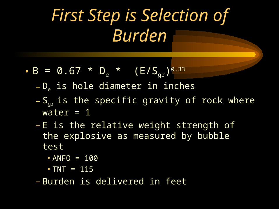
First Step is Selection of Burden
• B = 0.67 * De * (E/Sgr)0.33
– De is hole diameter in inches
– Sgr is the specific gravity of rock where water = 1
– E is the relative weight strength of the explosive as measured by bubble test
• ANFO = 100• TNT = 115
– Burden is delivered in feet

Burden Corrections for Local Conditions
• Confinement near rear of the shot– Bc = B * 0.9
• Bedding Dips into Pit and Aides Toppling
• Bt = B * 1.18

Burden Corrections
• Bedding Dipping Into Face and Holding Material Back– Bf = B * 0.95
• Heavy Cracked and Degraded Rock– Bd = B * 1.3
• Thin Layers and Tight Joints– Bl = B * 1.1

More Burden Adjustments
• Massive Intact Rock– Bm = B * 0.95
• Sometimes Need to Apply Several Adjustments at Once
• Example Pick Burden for Back Row of A Shot in Hard Massive Limestone Using ANFO in 3 inch Hole– 0.95 * 0.9 * 0.67 * 3 * (100/2.6) 0.33 = 5.73 ft– Round and call it 5 ft 9 inches

Controlling Cratering
• Cratering is where material is blasted upward rather than to the side
• Cratering results from lighter free face to surface than into pit - characterized in a stiffness ratio

Stiffness Ratio
• Stiffness Ratio = BH/ B
– where BH is Bench Height
– B is the Burden
• Target Stiffness Ratios– 3 to 4 is normal range– > 4 does not improve fragmentation (may risk
cut-offs much above 6)– 2 - redesign if you can– < 2 - Get someone you don’t like near shot

Stiffness Ratio Example
• What is the Stiffness Ratio for a 40 foot bench with 6.5 feet of burden on each hole– 40 / 6.5 = 6.15
• Shot won’t crater• No real advantage to such a high bench
and small hole• May need to watch for cut-off problems in
later practice or other equations
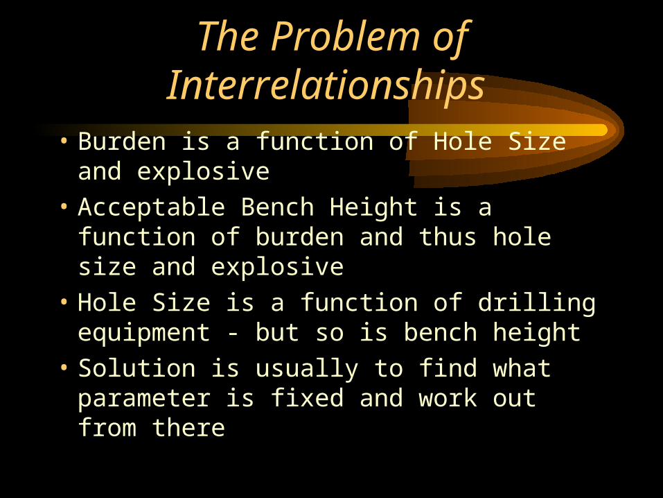
The Problem of Interrelationships
• Burden is a function of Hole Size and explosive
• Acceptable Bench Height is a function of burden and thus hole size and explosive
• Hole Size is a function of drilling equipment - but so is bench height
• Solution is usually to find what parameter is fixed and work out from there
Suppose Bench Height is Fixed
• In a quarry thickness of rock layers may set• May have been set in a previous mine plan• May be fixed by grade control constraints in
metal mine– need to be able to selectively mine– can’t scramble ore face with explosives
• Working Height of Equipment may Set

Solving for Maximum Allowable Hole Size on a Fixed Bench
• Combining the Burden and Stiffness Ratio formulas and backsolving hole size– For SR = 2 , L = Bench Height = 40, E = 100,
Sgr = 2.6
– L / (2 * { E/ Sgr } 0.33) = 6 inches
• Holes larger than 6 inches will likely cause cratering - smaller size is desirable
Solving with a Fixed Hole Size
• Can Occur for Fixed Drilling Equipment• Can Determine a minimum acceptable bench
height with an approximation - Rule of 5– Lmin = 5 * De
– If De = 3 inch hole then Lmin = 15 ft
• Check– 15 / 6.37 = 2.35 ft (6.37 from burden formula with
ANFO and 2.6 Sgr)

What if I have no constraints and I’m Lost
• Most Real Problems Have Hidden Constraints
• Equipment may fix– A Truck size usually constrains loader and
loaders have digging height that may fix the bench
– A given type of drill can only drill holes of specific size range
– Hole loading technique may limit bench height

Finding Hidden Constraints
• Geology may Constrain– Need to mine certain intervals
• quarry rock quality control• toxic or substitute topsoil rock in coal mine
– Grade Control• height of bench averages out high and low grades
and may limit selective mining
– Need to Manipulate Problem Layers• hard layer on top won’t fragment in stemming zone• In middle may cause cut-offs

Finding Constraints
• Performance may constrain– May require certain fragmentation characteristics
or costs• fragmentation usually more uniform with smaller holes
and benches• fragmentation usually cheaper with larger holes and
benches
• Regulations may constrain– Some localities limit bench height for safety– Blast Vibration may limit charge length

Picking Stemming Length
• Stemming is the inert material places at the top of hole to constrain fly rock and noise
• T = 0.7 to 1 * B– where T is stemming in feet– use 0.7 for river gravel (digs into side of
hole and holds better)– use 1 for drill cuttings

Problems with River Gravel
• Gravel must be size to tightly fill the hole and not get hung-up (leaving void space where inert fill was required)
• Hole Diameter should be 20 times hole for good fill and no hang-ups– Sz = 0.05 * De
• Where Sz is the size in inches for gravel• If lot of gravel is finer it is probably drill cuttings and
won’t dig into side of hole

Get Subgrade
• Subgrade is length of drilling below level of next bench needed to pull the toe and keep a level bench surface
• J = 0.3 * B– where J is subgrade in ft
• Example– 0.3 * 6.5 = 2 ft of subgrade

Hole Spacing
• Depends on Stiffness Ratio and the Delay Timing on the Shot
• If SR < 4 and entire row is on single delay (no delay between holes)– S = ( L + 2*B) /3
• where S is the spacing
– Example - 15 foot bench with 6.5 ft burden• (15 + 13) /3 = 9 ft 4 inches
• Spacing to Burden Ratio (9.333/ 6.5 ) = 1.44

More Hole Spacing
• If SR < 4 but interhole delay is practiced
• S = ( L + 7*B) / 8
• Example– ( 15 + 7 * 6.5 )/8 = 7.562 ft
• Checking Spacing to Burden Ratio– 7.562 / 6.5 = 1.163

Additional Hole Spacings
• If SR > 4 and row is instantly fired– S = 2 * B
• If SR > 4 and row uses interhole delay– S = 1.4 * B

Observations about Hole Spacing
• Note that instantaneous delays require greater hole spacing– problem is bridging between holes - bridge
crater and loose forward throw– inner hole delay reduces problem– also gives us a clue on how to pre-split
• Lower SR allows holes closer– Lower SR comes from larger holes with less
powder and less tendency to bridge

Choosing a Primer Position
• Bottom Prime is Standard– Primer overdrives explosive and bottom of hole
and better kicks out toe– Kicks out bottom and collapses top for better
collected muckpile near face
• Top Prime– May overdrive explosive below stemming zone
and improve caprock break-up– Topples rock away from face to spread out
muck pile

Other Primer Placement Strategies
• Place Extra Boosters just below hard rock intervals– Overdrives the explosive for breaking up
rock
• Double Prime hole if powder column is too long or one zone produces cut-offs
• May have multiple explosive decks with inner deck stemming in single hole
The Cut-Off Risk Problem
• Cut-off involves a break in the detonation continuity of a powder column– Effects fragmentation performance– Can be a hazard to later mining operations
• Control is based on crack propagation from one hole to the next or to the face– Assume that cracks propagate at 20% of the
velocity of the p wave through rock

Cut-Off Formula
• Pcmax = 5 * B * Ve/ Vp + J
– Ve = velocity of detonation of explosive
– Vp = p wave velocity in rock
– Pcmax = longest powder column that can reliably detonate without risk of cut-offs
• Note that this will tend to form an upper limit on bench height for a given hole size - while cratering will form a lower limit

Review that 3 inch hole on a 40 ft bench where SR was > 6
• 5 * 6.5 * 11,000/ 12,000 + 2 = 31.79 ft
• But the powder column on a 40 foot bench is 37.5 feet!
• This bench is prone to cut-offs
• If can’t shorten bench or increase holes size then may want to consider double priming

Calculate Delay Timing
• Delays between rows in blast– Chosen based on avoiding backbreak,
vibration and cut-offs and creating the desired muck-pile shape
• Must be > 2 ms/ ft of burden– will backbreak from inadequate time for rock
movement if less
• 3 ms/ ft will cause pile high and close to the face

Timing Between Rows
• 4 ms/ft gives an average muck pile distribution and is usually safe from cut-offs
• 6 ms/ft gives a spread out muck pile with some cut-off risk– material starts out fast and slows - later rows
pile up into material blast front and are held back
– long delay times get front out of way of later material
Long Timing Between Rows
• 7 to 14 ms/ft is the range used for cast blasting– warning above 8 ms/ft the cut-off risk rises
rapidly
• 10 to 20 ms/ft is used on deep back rows to allow material in front to move and avoid backbreak without alteration of the drilling pattern

Inner Hole Delay Timing
• Timing between holes in the same row is controlled by material being blasted
• Sands, Loams, Coal (soft and spongy) use 1.8 to 2.1 ms/ft
• Limestone, Shale and Salt (medium grade sedimentary) use 1.5 to 1.8 ms/ft
• Quartzite, Basalt, Gneiss 1.2 to 1.5
• Diabase, Magnetite, Mica Shist, Compact Gneiss 0.9 to 1.2

Regulatory Constraints
• The more powder that blows on one delay the greater the vibration
• Regulations normally limit maximum vibration and thus charge that can be fired on one delay
• Charges detonating within 8 ms of each other are considered to be on the same delay

Supply Constraints
• Delays come in only specific delay times– in ms series the lower delays are every 25
ms up to 200 and every 50 up to about 500
• Can extend options with sequential blasting machines that send separate pulses at a fixed or now computer selected interval
• Delays on big patterns are harder than you think.

Du Pont Millisecond Delay Series Blasting Caps

Coal Mining Delay Sequence Caps