Embed Size (px)
Citation preview
First-Storey Isolation Concept for
Multi-Performance Seismic Design of Steel Buildings I. Ricci, S. Gagliardi, G. Gasparini, S. Silvestri, T. Trombetti & M. Palermo Department DICA, University of Bologna, Italy.
SUMMARY: In this paper the design process of a first-storey seismic isolated steel frame building is developed within the framework of performance based seismic design. In detail the first storey seismic isolation is realized through the insertion of special hysteretic steel devices (called crescent shaped braces) which allows to satisfy pre-selected performance objectives. The basic idea of design process is the separation between the vertical and horizontal load resisting systems which allow to develop an optimized multi-performance seismic design. The design tools are based on the direct displacement based design procedures and capacity spectrum method, while the verification of the seismic performance of the designed building is obtained by mean of a set of non-linear time history analysis. Keywords: first-storey isolation, multi performance objectives, crescent-shaped braces. 1. INTRODUCTION The design of building structures capable of providing prescribed seismic performances represents the objective of the Performance-Based-Seismic-Design approach (Vision 2000, 1995, Bertero and Bertero, 2002). The bases of the PBSD lie in the capacity of defining and satisfying a plurality of performance objectives (Bertero and Bertero, 2002), i.e. in the capacity of predict that a given structural system will perform in a selected manner (i.e. performance level) under a given seismic intensity (i.e. earthquake design level). Typically, the traditional seismic design of the structures is carried out using a Force-Based Design approach (FBD, borrowed from the common approach for static design). Moreover the load-bearing system (first designed for vertical loads) typically coincides with the horizontal resisting system (i.e. the resisting system against seismic action). In such a way the same structural system acts for both vertical and horizontal actions. As a consequence the dynamic response of the whole system is somehow passively evaluated and not “governed” by the designer. On the other hand, many recent contributions in the field of seismic engineering introduced new design approaches in order to provide the structural system able to behave in a prescribed way under an earthquake of a certain intensity. Among others, the most remarkable are: (i) PBSD approach (Vision 2000, 1995, Bertero and Bertero, 2002) that , as mentioned before, formalized the need of satisfying a multiplicity of performance objectives, (ii) Direct Displacement- Based Design (DDBD) (Priesteley et al., 2007) introduced the displacement analysis as a tool for seismic design of structures, (iii) Capacity Spectrum method (Freeman, 2004) allow to compares the “capacity of a structure to resist lateral forces to the demands of earthquake response spectra in a graphical presentation that allows a visual evaluation of how the structure will perform when subjected to earthquake ground motion” (Freeman 2004); (iv) the use of special devices and techniques (e.g. unbounded braces, dampers (Christopoulos and Filiatrault, 2007), seismic isolators (Kelly, 1997)) adopted for the mitigation of the seismic effects upon the structure, which allows the conceptual separation between
the structural systems resisting to vertical and horizontal loads; (iv) Soft-Storey conceptual design: earthquake-resistant structures can be achieved “by designing a shock-absorbing soft story” upon which the structure will remain within the elastic range, so that high intensity earthquake motions are confined “to controlled areas in the lower part of the building” (Fintel and Khan, 1968). This paper presents an approach for a full-controlled optimized seismic design of structures which combines same of the recent contributions and overcomes the traditional design approach. In detail, the seismic design is developed with reference to a first-storey seismic based isolated steel frame building. 2. THE BASIC IDEA In order to search for the optimized seismic behaviour of the structure in the multi-objective context of the PBSD, the basic idea is to provide a complete separation between the Vertical-load Resisting System (VRS) and the Horizontal-load Resisting System (HRS) of the structure. This conceptual and physical separation allows the designer to choose and design the HRS in order to achieve an optimized seismic behaviour. A full optimization lies in the achievement of pre-selected seismic performance objectives. These objectives are selected and expressed in terms of expected levels of damage resulting from expected levels of earthquake ground motions. A performance objective is a coupling of an expected performance level under a prescribed level of seismic ground motion (Bertero and Bertero, 2002). The actual seismic codes typically refer to the followings basic multiple performance objectives for a common building (POs, Vision 2000, 1995):
• PO-1: “Frequent earthquake + Fully Operational (FO)”: under a frequent earthquake negligible damage for both structural and non-structural elements can occur, facilities can continue with no disruption;
• PO-2: “Occasional earthquake + Operational (O)”: under an occasional earthquake negligible damage for structural elements and moderate damage for the non-structural ones, facilities continue in operation with minor damage and minor disruption only in non-essential services;
• PO-3: “Rare earthquake + Life-Safe (LS)”: life safety is substantially protected, damage to structural and non-structural elements is moderate to extensive;
• PO-4: “Very rare earthquake + Near-Collapse (NC)”: life safety is at risk, damage is severe but structural collapse is prevented.
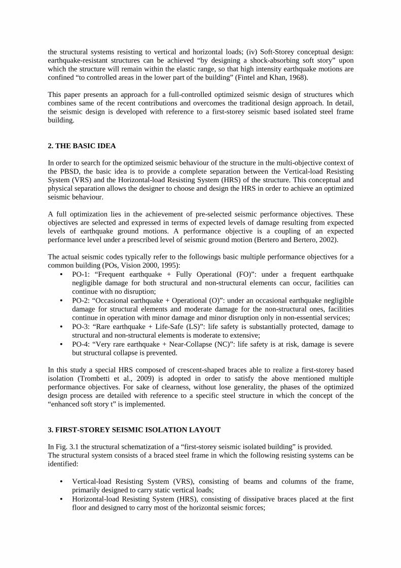
In this study a special HRS composed of crescent-shaped braces able to realize a first-storey based isolation (Trombetti et al., 2009) is adopted in order to satisfy the above mentioned multiple performance objectives. For sake of clearness, without lose generality, the phases of the optimized design process are detailed with reference to a specific steel structure in which the concept of the “enhanced soft story t” is implemented. 3. FIRST-STOREY SEISMIC ISOLATION LAYOUT In Fig. 3.1 the structural schematization of a “first-storey seismic isolated building” is provided. The structural system consists of a braced steel frame in which the following resisting systems can be identified:
• Vertical-load Resisting System (VRS), consisting of beams and columns of the frame, primarily designed to carry static vertical loads;
• Horizontal-load Resisting System (HRS), consisting of dissipative braces placed at the first floor and designed to carry most of the horizontal seismic forces;
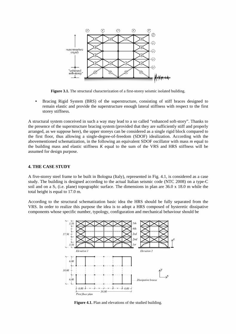
Figure 3.1. The structural characterization of a first-storey seismic isolated building.
• Bracing Rigid System (BRS) of the superstructure, consisting of stiff braces designed to remain elastic and provide the superstructure enough lateral stiffness with respect to the first storey stiffness.
A structural system conceived in such a way may lead to a so called “enhanced soft-story”. Thanks to the presence of the superstructure bracing system (provided that they are sufficiently stiff and properly arranged, as we suppose here), the upper storeys can be considered as a single rigid block compared to the first floor, thus allowing a single-degree-of-freedom (SDOF) idealization. According with the abovementioned schematization, in the following an equivalent SDOF oscillator with mass m equal to the building mass and elastic stiffness K equal to the sum of the VRS and HRS stiffness will be assumed for design purpose. 4. THE CASE STUDY A five-storey steel frame to be built in Bologna (Italy), represented in Fig. 4.1, is considered as a case study. The building is designed according to the actual Italian seismic code (NTC 2008) on a type-C soil and on a S1 (i.e. plane) topographic surface. The dimensions in plan are 36.0 x 18.0 m while the total height is equal to 17.0 m. According to the structural schematization basic idea the HRS should be fully separated from the VRS. In order to realize this purpose the idea is to adopt a HRS composed of hysteretic dissipative components whose specific number, typology, configuration and mechanical behaviour should be
Figure 4.1. Plan and elevations of the studied building.
designed in order to satisfy pre-selected performance objectives (which will be detailed in the next section, i.e. sec. 5.1). The upper storeys are designed to behave elastically trough the introduction of traditional concentric X-braces, specifically dimensioned on the basis of Capacity Design criteria. In the plan view (Fig. 4.1), it can be seen that half of column profiles are oriented along the x-direction, while the remaining half are oriented in the perpendicular one (i.e. y-direction), so that the building has the same stiffness in both principal directions. Beams are all pin connected to the columns. On intermediate floors and on the roof a dead load of 10.00 kN/m2 and 6.25 kN/m2 has been considered, respectively. The building total weight is equal to 30000 kN. The VRS has been designed in order to carry only the vertical loads (in particular, columns and beams are made up of HE400B and IPE500 European profiles, respectively). 5. OPTIMIZED SEISMIC DESIGN PROCESS In this section the design approach adopted for the dimensioning of the HRS is fully developed with reference to the case study introduced in section 3. The main phases of the design approach (seismic design) are the followings:
• Definition of the performance objectives (subsection 5.1); • Evaluation of the performance objectives curve (subsection 5.2); • Design of the HRS (subsection 5.3); • Graphical representation of the seismic demand vs. structure capacity (subsection 5.4);
5.1. Definition of the performance objectives In order to identify the performance objective it is first necessary to define the seismic intensity levels (i.e. the design earthquakes) corresponding to the achievement of each structure performance level. In this study the evaluation of the building seismic response will be developed according to the Capacity spectrum method (Freeman, 2004 ), thus adopting a spectrum Acceleration - Displacement representation. For design purposes, seismic actions can be conveniently represented through the well known concept of response spectrum (Newmark and Hall, 1982). The pseudo-acceleration response spectrum A(T) is usually expressed through relationships which involves the Peak Ground Acceleration (PGA) and some other parameters characteristic of the construction site. The so-called “velocity-constant” (Newmark and Hall, 1982) branch of the pseudo acceleration response spectrum has the following representation:
η⋅⋅⋅=T
TCTA C
A PGA)( (5.1)
where CA is an amplification factor (≅ 2.5), TC is the characteristic period value at the beginning of the constant-velocity branch and η ≤ 1 is a reduction coefficient accounting for damping ratios higher than the 0.05 (i.e. inherent damping). Displacement spectrum δ(T) can be derived from the correspondent Acceleration spectrum assuming the oscillator to be harmonic:
ηπ
δ ⋅⋅⋅⋅== TTCT
TAT CA PGA4
)()( 2
2
(5.2)
For the present case study, based on Italian code prescriptions (NTC 2008), the four seismic input levels reported in Table 5.1, appropriate for ordinary buildings, are considered. Table 5.1. Earthquake design levels adopted for the case study
Earthquake design levels Response Spectra Parameters
p PGA (g) TC (s) CA 1 EQ-1 81% 0.080 0.424 2.478 2 EQ-2 63% 0.101 0.439 2.482 3 EQ-3 10% 0.243 0.479 2.404 4 EQ-4 5% 0.295 0.484 2.436 p indicates the earthquake probability of occurrence in a 50-year reference period The Performance Levels corresponding to each earthquake design level are generally defined based on building destination and/or specific requirements of the client. As pointed out in Bertero and Bertero (2002), performances under a considered seismic input can be in general defined through a number of global Damage Indexes, capable of describing the degree of damage for both structural and non-structural elements. For the present case study, these parameters should be preferably expressed in terms of either displacements or forces so as to be able to define Performance Objectives in the same diagram with seismic demand and then identify the structure “target pushover” curve as well. Thus, each Damage Index condition is finally to be formulated in force/displacement terms. For each Performance Level, specific mathematical conditions (usually expressed by inequalities) involving the selected Damage Indexes are introduced, depending on client’s requirements or specific destination, importance and typology of the building. In Table 5.2 the Performance Conditions adopted for the present case study are summarized. Table 5.2. Performance conditions for each earthquake design level
Damage Index Performance Levels (Limit States)
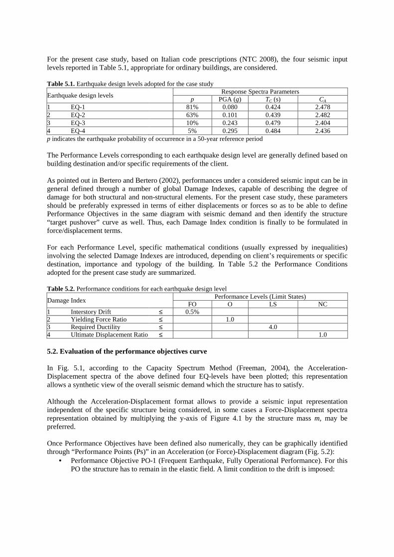
FO O LS NC 1 Interstory Drift ≤ 0.5% 2 Yielding Force Ratio ≤ 1.0 3 Required Ductility ≤ 4.0 4 Ultimate Displacement Ratio ≤ 1.0 5.2. Evaluation of the performance objectives curve In Fig. 5.1, according to the Capacity Spectrum Method (Freeman, 2004), the Acceleration-Displacement spectra of the above defined four EQ-levels have been plotted; this representation allows a synthetic view of the overall seismic demand which the structure has to satisfy. Although the Acceleration-Displacement format allows to provide a seismic input representation independent of the specific structure being considered, in some cases a Force-Displacement spectra representation obtained by multiplying the y-axis of Figure 4.1 by the structure mass m, may be preferred. Once Performance Objectives have been defined also numerically, they can be graphically identified through “Performance Points (Ps)” in an Acceleration (or Force)-Displacement diagram (Fig. 5.2):
• Performance Objective PO-1 (Frequent Earthquake, Fully Operational Performance). For this PO the structure has to remain in the elastic field. A limit condition to the drift is imposed:
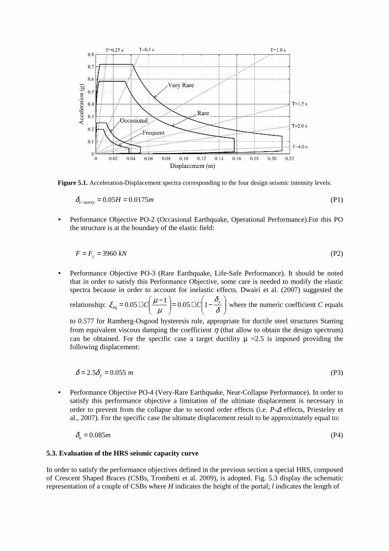
Figure 5.1. Acceleration-Displacement spectra corresponding to the four design seismic intensity levels.
1 0.05 0.0175storey H mδ − = = (P1)
• Performance Objective PO-2 (Occasional Earthquake, Operational Performance).For this PO
the structure is at the boundary of the elastic field:
3960 yF F kN= = (P2)
• Performance Objective PO-3 (Rare Earthquake, Life-Safe Performance). It should be noted
that in order to satisfy this Performance Objective, some care is needed to modify the elastic spectra because in order to account for inelastic effects. Dwairi et al. (2007) suggested the
relationship:
−+=
−+=δδ
µµξ yCC 105.0
105.0eq where the numeric coefficient C equals
to 0.577 for Ramberg-Osgood hysteresis rule, appropriate for ductile steel structures Starting from equivalent viscous damping the coefficient η (that allow to obtain the design spectrum) can be obtained. For the specific case a target ductility µ =2.5 is imposed providing the following displacement:
2.5 0.055 y mδ δ= = (P3)
• Performance Objective PO-4 (Very-Rare Earthquake, Near-Collapse Performance). In order to
satisfy this performance objective a limitation of the ultimate displacement is necessary in order to prevent from the collapse due to second order effects (i.e. P-∆ effects, Priesteley et al., 2007). For the specific case the ultimate displacement result to be approximately equal to:
0.085u mδ = (P4)
5.3. Evaluation of the HRS seismic capacity curve In order to satisfy the performance objectives defined in the previous section a special HRS, composed of Crescent Shaped Braces (CSBs, Trombetti et al. 2009), is adopted. Fig. 5.3 display the schematic representation of a couple of CSBs where H indicates the height of the portal; l indicates the length of
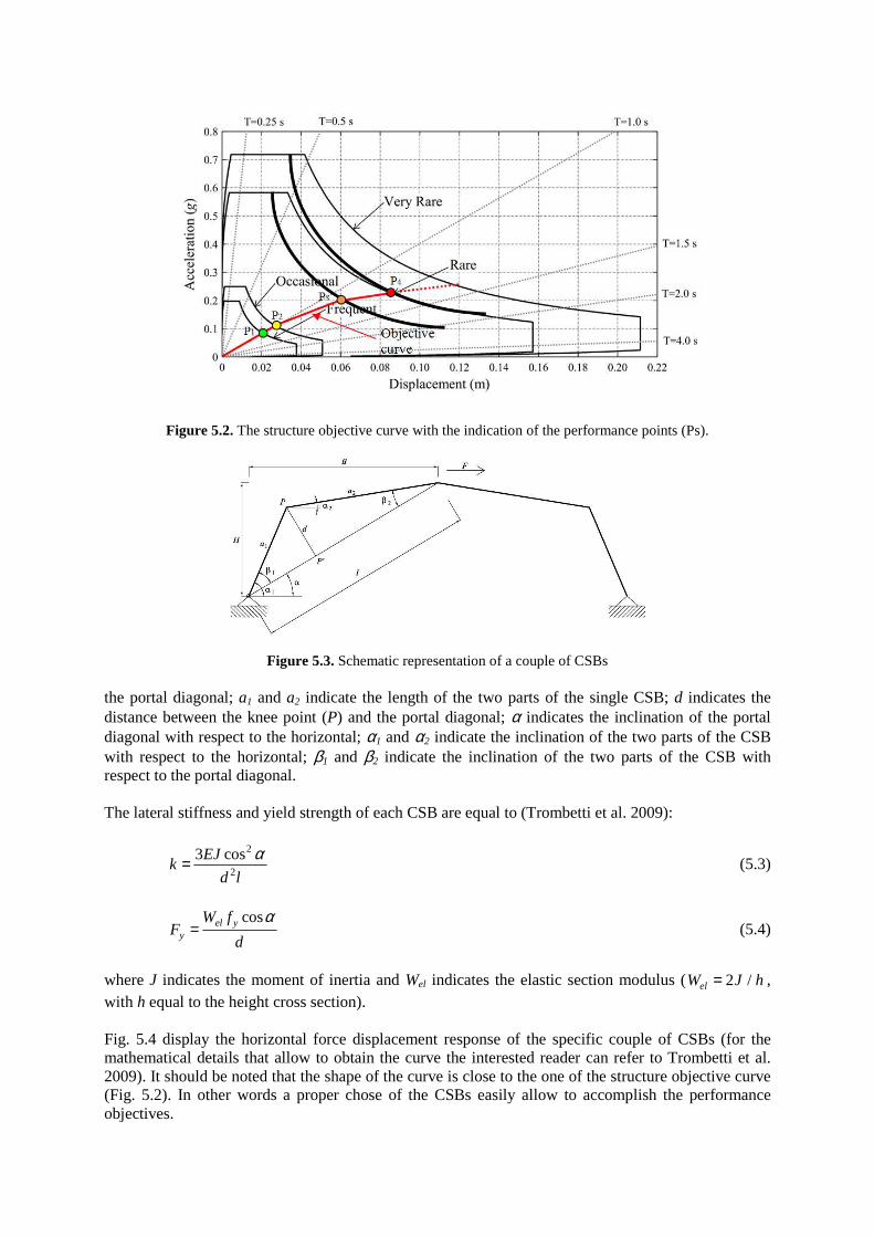
Figure 5.2. The structure objective curve with the indication of the performance points (Ps).
Figure 5.3. Schematic representation of a couple of CSBs the portal diagonal; a1 and a2 indicate the length of the two parts of the single CSB; d indicates the distance between the knee point (P) and the portal diagonal; α indicates the inclination of the portal diagonal with respect to the horizontal; α1 and α2 indicate the inclination of the two parts of the CSB with respect to the horizontal; β1 and β2 indicate the inclination of the two parts of the CSB with respect to the portal diagonal. The lateral stiffness and yield strength of each CSB are equal to (Trombetti et al. 2009):
2
2
3 cosEJk
d l
α= (5.3)
cosel y
y
W fF
d
α= (5.4)
where J indicates the moment of inertia and Wel indicates the elastic section modulus ( 2 /elW J h= , with h equal to the height cross section). Fig. 5.4 display the horizontal force displacement response of the specific couple of CSBs (for the mathematical details that allow to obtain the curve the interested reader can refer to Trombetti et al. 2009). It should be noted that the shape of the curve is close to the one of the structure objective curve (Fig. 5.2). In other words a proper chose of the CSBs easily allow to accomplish the performance objectives.
Figure 5.4. Force displacement response for the single CSB (in tension and compression, thin curves) and for the couple of CSB (tick curve)
Clearly, due to geometric non linearity, the behaviour in tension differs from the behaviour in compression. For the case study (idealized as a SDOF system), the whole structure capacity can be seen as the sum of the contributions of VRS and HRS. Consequently, as the VRS was already designed (i.e. its lateral resisting capacity is known), the HRS capacity can be simply determined as the difference between the overall capacity the structure and VRS capacity. In detail, in the specific case 24 couples of CSBs (HEB 240B European profile) allows to satisfy the performance objectives. 5.3. Graphical representation of the seismic demand and structure capacity Once both the VRS and HRS are designed it is possible to represent (according to capacity spectrum method) in the same diagram both the seismic demand and the structure capacity. Fig. 5.4 provides the synthetic representation of the overall building capacity over curve (tick curve) and the VRS and HRS capacity curves (dotted thin curves). It is possible to observe that the actual structure capacity curve is almost identical to the objective curve. 6. THE NUMERICAL VERIFICATION In order to verify the effectiveness of the presented design process a finite element model of the studied building has been developed using the commercial software SAP2000 (Fig. 6.1 a). Four sets of spectrum compatible accelerograms (Fig. 6.1 b) have been considered according to the EQ levels reported in Table 5.1. Each set of accelerograms, consisting of seven natural ground motion records, has been scaled to the PGA of the corresponding EQ level. Non linear time history analyses have been performed in order to evaluate the seismic performance of the building. The main results of the time-history analyses are plotted in Fig. 6.2 where each point indicates the values of the maximum base shear and ultimate displacement corresponding to each time-history analysis, while the dotted vertical lines indicates the mean values of ultimate displacement achieved at each level of seismic intensity. Inspection of the graph allows to observe that seismic response of the
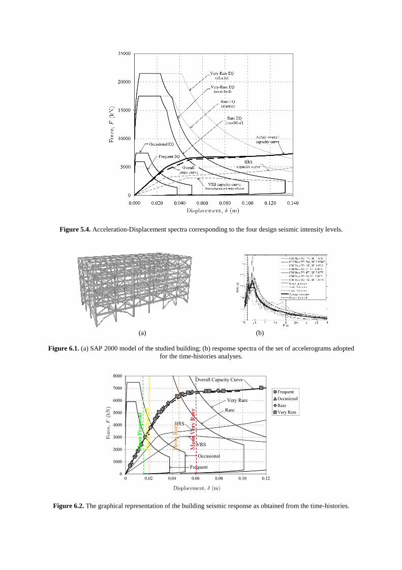
Figure 5.4. Acceleration-Displacement spectra corresponding to the four design seismic intensity levels.
(a) (b)
Figure 6.1. (a) SAP 2000 model of the studied building; (b) response spectra of the set of accelerograms adopted
for the time-histories analyses.
Figure 6.2. The graphical representation of the building seismic response as obtained from the time-histories.
building is very close (in mean) to the expected one. CONCLUSIONS In this paper, a five-storey steel frame building is designed in order to achieve pre-selected multi-performance seismic objectives. In order to obtain the target objectives a total separation between vertical and horizontal load-resisting systems is realized. A further improvement to structural layout has been obtained through a first-storey seismic base isolation, thus providing the structure a simple SDOF configuration and realizing an “enhanced soft-storey” layout. The proposed design/verification approach involves a first phase of structure dimensioning by fitting as close as possible the actual pushover curve of the structure to a “target pushover curve”, representative in a Force-Displacement diagram of all the given target conditions; a central role in this process is obviously held by the horizontal resisting system and its dissipative components. Once every structural member is known, a second phase of verification of seismic behaviour under a specific accelerograms can be carried out through non-linear time-history analyses. Non-linear time history analyses performed on this and other similar case studies (Trombetti et al., 2009) demonstrates a good agreement between design and verification results, and also that the proposed approach can be a valid option for a optimized seismic design of building structures. REFERENCES Bertero, R.D. and Bertero, V.V. (2002), Performance-based seismic engineering: the need for a reliable
conceptual comprehensive approach, Earthquake Engineering and Structural Dynamics, 31(3), 627-652. California OES (Office of Emergency Service) 1995, Vision 2000: Performance-Based Seismic Engineering of
Buildings, Prepared by SEAOC (Structural Engineers Association of California, Sacramento, CA, USA. Christopoulos, C. and Filiatrault, A. (2007), Principles of Passive Supplemental Damping and Seismic Isolation,
IUSS Press, Pavia, Italy. NTC 2008 Norme Tecniche per le Costruzioni. Italian Ministerial decree 14/01/2008, S.O. n.30 alla G.U. n.29
del 04/02/2008 (in Italian). Dwairi, H.M., Kowalsky, M.J. and Nau, J.M. (2007), Equivalent Viscous Damping in Support of Direct
Displacement-Based Design”, Journal of Earthquake Engineering 11:512-530. Freeman, S.A. (2004), Review of the Development of the Capacity Spectrum Method, ISET Journal of
earthquake Technology 41(1): 1-13, Paper No. 438. Kelly, J. M. (1997) Base isolation: linear theory and design, Earthquake Spectra, 6(2), 223-244. Priestley, M.J.N., Calvi, G.M. and Kowalsky, M.J. (2007), Direct Displacement-Based Seismic Design of
Structures, IUSS Press, Pavia. Trombetti, T., Silvestri, S., Gasparini, G. and Ricci, I. (2009), Stiffness-Strength-Ductility Design Approaches
for Crescent-Shaped Braces, The Open Construction and Building Technology Journal 3, 127-140.