Embed Size (px)
Citation preview

www.Fisher.com
Fisher™ C1 Pneumatic Controllers andTransmittersFisher C1 controllers and transmitters continue thetradition of durable and dependable Fisher pressureinstrumentation while addressing air/gas consumptionconcerns. The C1 is used wherever durable anddependable pressure instrumentation is required. Theuse of this product in demanding applications, such asthose found in chemical process, gas, and oilproduction industries, demonstrates its versatility. TheC1 can reduce steady-state air/gas consumption to aslittle as 1/10th that of previous products.
C1 controllers compare sensed process pressure (ordifferential pressure) with an operator-adjusted setpoint, and send a pneumatic signal to an adjacentcontrol element that maintains the process pressure ator near the set point value. C1 transmitters senseprocess variables and send out a pneumatic signal,usually to an indicating or recording device thatdirectly indicates the process measurement.
Unless otherwise noted, all NACE references are toNACE MR0175 / ISO15156 & NACE MR0103.
Features� Wide Range of Sensing Elements—A Bourdon tube is
available for high pressures or bellows for vacuumand low pressures. Either kind of sensing elementcan be installed in the case with the controller ortransmitter. Two interchangeable ranges of outputbellows and gauges also are available.
� Reduced Air/Gas Consumption—The C1 pneumaticcontroller is an energy efficient choice, helping toimprove profits and uptime. Steady-stateconsumption rate is less than the 6 scfhrequirement set for the oil and gas industry by theUS Environmental Protection Agency (New SourcePerformance Standards Subpart OOOO,EPA‐HQ‐QAR‐2010-0505).
FISHER C1 PNEUMATIC CONTROLLERYOKE-MOUNTED ON CONTROL VALVE ACTUATOR
� Sour Service Capability—Materials are available forapplications handling sour process fluids. Theseconstructions comply with the metallurgicalrequirements of NACE MR0175 / ISO15156 & NACEMR0103. Environmental restrictions may apply.
� Mounting Versatility—Install the case on a panel,wall or pipestand, as well as directly on the controlvalve actuator.
� Reduced Maintenance Costs—A spring-out cleaningwire, shown in figure 4, provides for in-servicecleaning of the relay orifice.
� Proportional-Only, Proportional-Plus-Reset, andDifferential Gap Configurable—The C1 controllercan be configured to provide various modes ofcontrol.
(Features continued on page 3)
C1 Controllers and TransmittersD103291X012
Product Bulletin34.3:C1
August 2017
C1 Controllers and TransmittersD103291X012
Product Bulletin34.3:C1August 2017
2
Specifications
Available Configurations
See table 1
Input Signal
Pressure
Type: � Gauge pressure, � vacuum, � compoundpressure, or � differential pressure of a liquid or gasLimits: See table 2 or 3
Output Signal
Proportional or Proportional-Plus-Reset Controllersand Transmitters: � 0.2 to 1.0 bar (3 to 15 psig) or� 0.4 to 2.0 bar (6 to 30 psig) pneumatic pressuresignalDifferential Gap Controllers: � 0 and 1.4 bar (0 and 20 psig) or � 0 and 2.4 bar (0 and 35 psig)pneumatic pressure signalAction: Control action is field reversible between� direct (increasing sensed pressure producesincreasing output signal) and � reverse (increasingsensed pressure produces decreasing output signal).
Supply Pressure Requirements(1)
See table 4
Supply Pressure Medium
Air or Natural Gas
Supply medium must be clean, dry, and noncorrosiveand meet the requirements of ISA Standard 7.0.01 orISO 8573-1.
A maximum 40 micrometer particle size in the airsystem is acceptable. Further filtration down to 5micrometer particle size is recommended. Lubricantcontent is not to exceed 1 ppm weight (w/w) orvolume (v/v) basis. Condensation in the air supplyshould be minimized
Steady-State Air Consumption(2)(3)
0.2 to 1.0 bar (3 to 15 psig): 0.08 normal m3/hour(3 scfh)0.4 to 2.0 bar (6 to 30 psig): 0.12 normal m3/hour (4.5 scfh)
Supply and Output Connections
1/4 NPT internal
Supply and Output Pressure Gauge Ranges
See table 5
Proportional Band Adjustment
For Proportional-Only Controllers: Full outputpressure change adjustable from � 2% to 100% of thesensing element range for 0.2 to 1.0 bar (3 to 15 psig)or � 4% to 100% of the sensing element range for 0.4to 2.0 bar (6 to 30 psig)
For Proportional-Plus-Reset Controllers: Full outputpressure change adjustable from � 3% to 100% of thesensing element range for 0.2 to 1.0 bar (3 to 15psig), or � 6% to 100% of the sensing element rangefor 0.4 to 2.0 bar (6 to 30 psig)
Differential Gap Adjustment
For Differential Gap Controllers: Full output pressurechange adjustable from 15% to 100% of sensingelement range
Reset Adjustment
For Proportional-Plus-Reset Controllers: Adjustablefrom 0.01 to 74 minutes per repeat (100 to 0.01repeats per minute)
Zero Adjustment (Transmitters Only)
Continuously adjustable to position span of less than100% anywhere within the sensing element range
Span Adjustment (Transmitters Only)
Full output pressure change adjustable from 6 to100% of process sensing element range
Performance
Repeatability: 0.5% of sensing element rangeDead Band (Except Differential Gap Controllers(4)):0.1% of sensing element rangeTypical Frequency Response at 100% ProportionalBand:Output to Actuator: 0.7 Hz and 110 degree phase shiftwith 1850 cm3 (113 inches3) volume actuator atmid-strokeOutput to Positioner Bellows: 9 Hz and 130 degreephase shift with 0.2 to 1.0 bar (3 to 15 psig) output to33 cm3 ( 2 inches3 ) bellows
-continued-
C1 Controllers and TransmittersD103291X012
Product Bulletin34.3:C1
August 2017
3
Specifications (continued)
Ambient Operating Temperature Limits(1)
� Standard Construction: -40 to 71�C (-40 to 160�F)� High Temperature Construction: -18 to 104�C (0 to 220�F)
Anti-reset windup (differential pressure relief) andprocess pressure gauge options are only available inthe standard construction
Typical Ambient Temperature Operating Influence
Proportional Control only: ±3.0% of output span foreach 28�C (50�F) change in temperature between-40 and 71�C (-40 and 160�F) for a controller set at100% proportional bandReset Control only: ±2.0% of output span for each28�C (50�F) change in temperature between -40 and71�C (-40 and 160�F) for a controller set at 100%proportional bandTransmitters only: ±3.0% of output span for each28�C (50�F) change in temperature between -40 and71�C (-40 and 160�F) for a transmitter set at 100%span
Housing
Designed to NEMA 3 (Weatherproof) and IEC 529IP54 Specifications
Hazardous Area Classification
Complies with the requirements of ATEX Group IICategory 2 Gas and Dust
Meets Customs Union technical regulation TP TC012/2011 for Groups II/III Category 2 equipment
II Gb c T*XIII Db c T*X
Construction Materials
See tables 2, 3, and 6
Approximate Weight
8.2 kg (18 pounds)
NOTE: Specialized instrument terms are defined in ANSI/ISA Standard 51.1 - Process Instrument Terminology.1. The pressure and temperature limits in this document, and any applicable standard or code limitation should not be exceeded.2. Normal m3/hr: normal cubic meters per hour (m3/hr, 0�C and 1.01325 bar, absolute). Scfh: standard cubic feet per hour (ft3/hr, 60�F and 14.7 psig).3. To convert from air flow rate to natural gas flow rate multiply by 1.29.4. An adjustable differential gap (differential gap controllers) is equivalent to an adjustable deadband.
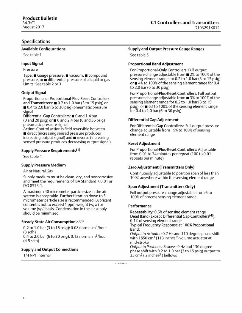
Table 1. Available Configurations
DESCRIPTION(1)
AVAILABLE CONFIGURATIONS
Pressure
Bourdon Tube Sensing Element (Gauge Pressure Only)
Bellows Sensing Element
Gauge Pressure Differential Pressure
Proportional controller
C1P C1B
C1DProportional-plus-reset
controller
Without anti-reset windup
With anti-reset windup - - -
Differential-gap controller - - -
Transmitter C1D
1. See figure 4 and 5 for construction details.
Features (continued)
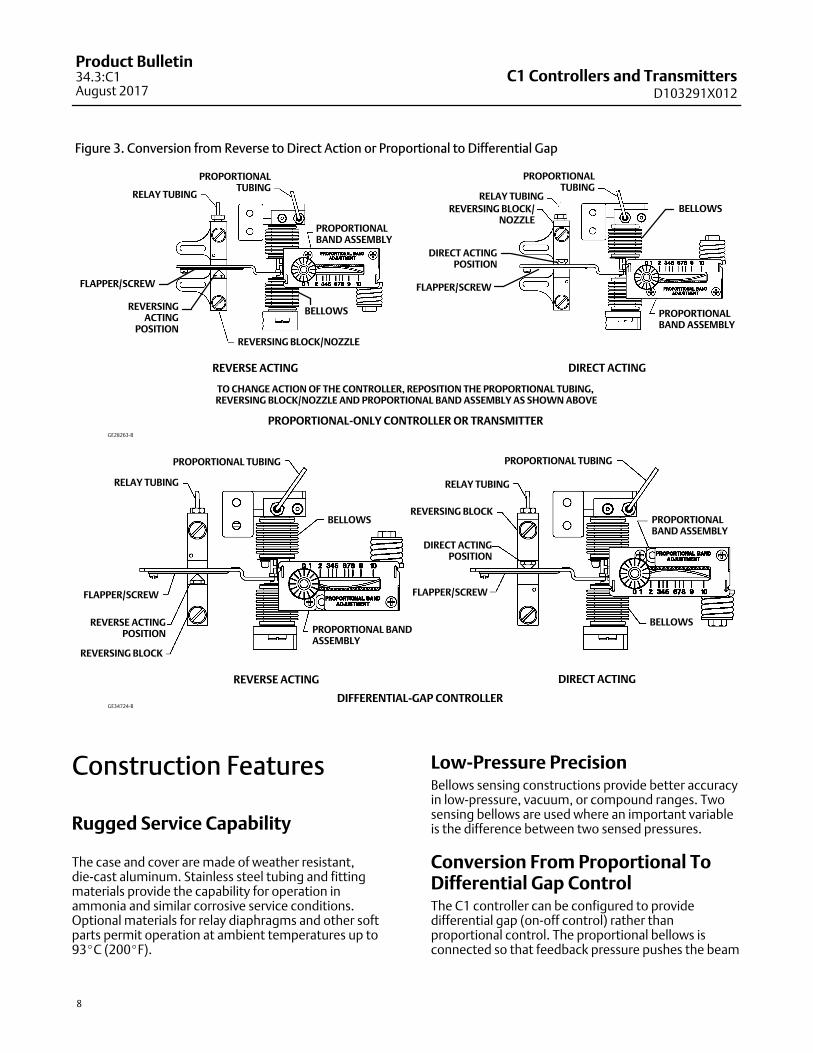
� Field Reversible—Switch action from direct toreverse or vice versa without additional parts. Asillustrated in figure 3, transfer the reversing block tothe opposite side of the flapper, invert theproportional band assembly and change thefeedback bellows tubing connections.
� Easy, More Accurate Adjustments—Make pressureset point, proportional band, and reset changeswith simple dial-knob controls that help to assurepositive settings.
� Sensitive Response—Area ratio of large relaydiaphragm to small relay diaphragm permits smallnozzle pressure changes to induce much greateroutput pressure changes.
C1 Controllers and TransmittersD103291X012
Product Bulletin34.3:C1August 2017
4
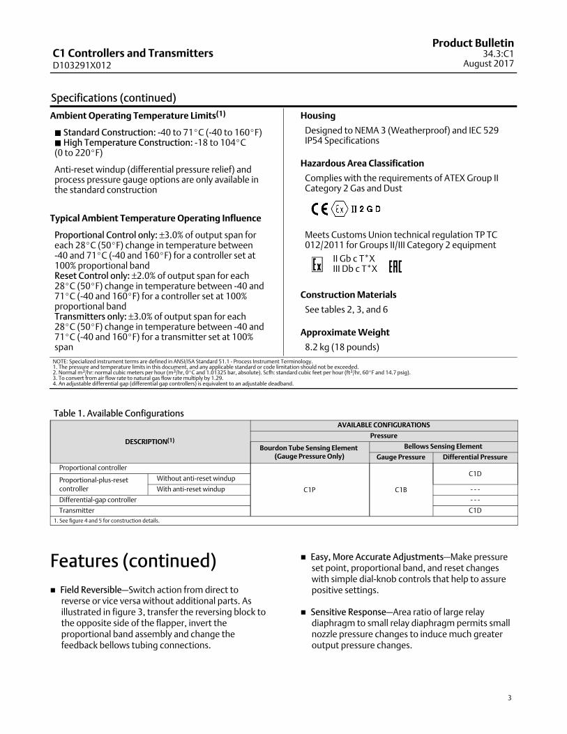
Table 2. Bourdon Tube Pressure Ranges and Materials
PRESSURE RANGES(1)MAXIMUM ALLOWABLE STATIC PRESSURE LIMITS(2)
MATERIAL(4)Standard With Optional Travel Stop(3)
Bar Psig Bar Psig Bar Psig
0 to 2.0
0 to 4.0
0 to 7.0
0 to 30
0 to 60
0 to 100
2.0
4.0
7.0
30
60
100
3.3
6.6
11
48
96
160
316 Stainless Steel
0 to 14
0 to 20
0 to 40
0 to 70
0 to 200
0 to 300
0 to 600
0 to 1000
14
20
40
70
200
300
600
1000
19
29
50
83
280
420
720
1200
0 to 100
0 to 200
0 to 350
0 to 1500
0 to 3000
0 to 5000
100
200
350
1500
3000
5000
115
230
380
1650
3300
5500
0 to 550
0 to 700
0 to 8000
0 to 10,000
550
700
8000
10,000
550
700
8000
10,000
1. Range marked on Bourdon tube may be in kPa (1 bar = 100 kPa).2. Bourdon tube may be pressured to limit shown without permanent zero shift.3. With travel stop set at 110% of the range.4. Bourdon tubes are also available in NACE compliant material. Contact your Emerson sales office or Local Business Partner for additional information.
Table 3. Bellows Pressure Ranges and Materials
PRESSURE RANGES
MAXIMUM ALLOWABLESTATIC PRESSURE LIMITS(1)
Brass ConstructionStainless SteelConstruction
Bar Psig Bar Psig
Gaugepressure
Vacuum0 to 150 mbar (0 to 60 inch wc)0 to 340 mbar (0 to 10 inch Hg)0 to 1.0 bar (0 to 30 inch Hg)
1.42.82.8
204040
- - -- - -6.9
- - -- - -100
Compoundpressure
75 mbar vac. to 75 mbar (30 inch wc vac. to 30 inch wc) 1.4 20 6.9 100
500 mbar vac. to 500 mbar (15 inch Hg vac. to 7.5 psig) 2.8 40 6.9 100
1.0 bar vac. to 1.0 bar (30 inch Hg vac. to 15 psig) 2.8 40 - - - - - -
Positivepressure
0 to 150 mbar (0 to 60 inch wc)0 to 250 mbar(2) (0 to 100 inch wc)0 to 350 mbar(3) (0 to 140 inch wc)0 to 0.35 bar (0 to 5 psig)0 to 0.5 bar (0 to 7.5 psig)
1.41.42.82.82.8
2020404040
- - -- - -- - -- - -- - -
- - -- - -- - -- - -- - -
0 to 0.7 bar (0 to 10 psig)0 to 1.0 bar (0 to 15 psig)0 to 1.4 bar (0 to 20 psig)0 to 2.0 bar (0 to 30 psig)
2.82.82.82.8
40404040
- - -6.9- - -6.9
- - -100- - -100
Differential pressure(4)
0 to 200 mbar (0 to 80 inch wc)0 to 0.7 bar (0 to 10 psi)0 to 1.4 bar (0 to 20 psi)0 to 2.0 bar (0 to 30 psi)
1.42.82.8- - -
204040- - -
- - -- - -- - -6.9
- - -- - -- - -100
1. Bellows may be pressured to limit shown without permanent zero shift.2. C1B transmitter only.3. Except C1B transmitter.4. The overrange limit for these sensing elements is a differential pressure equal to the maximum allowable static pressure limit.
Table 4. Supply Pressure Data
Output SignalNormal Operating Supply
Pressure(1)Maximum Allowable Supply Pressure To Prevent
Internal Part Damage(2)
Bar0.2 to 1.0 or 0 and 1.4 (differential gap) 1.4 2.8
0.4 to 2.0 or 0 and 2.4 (differential gap) 2.4 2.8
Psig3 to 15 or 0 and 20 (differential gap) 20 40
6 to 30 or 0 and 35 (differential gap) 35 40
1. If this pressure is exceeded, control may be impaired.2. If this pressure is exceeded, damage to the controller may result.
C1 Controllers and TransmittersD103291X012
Product Bulletin34.3:C1
August 2017
5
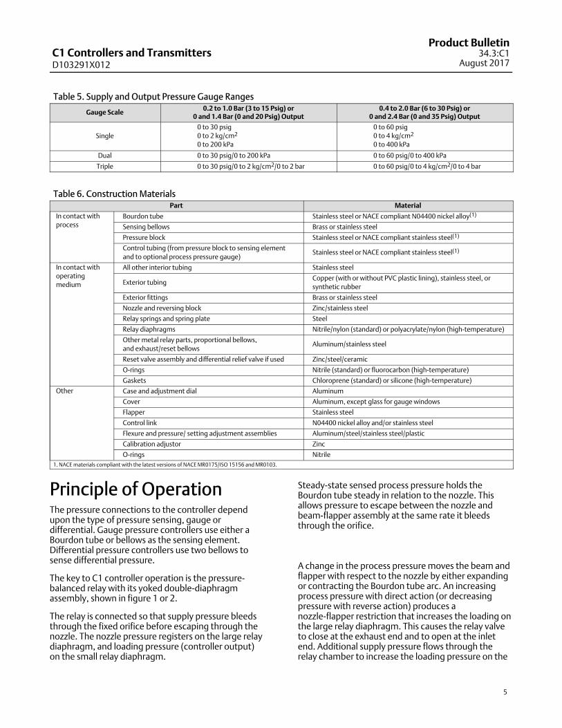
Table 5. Supply and Output Pressure Gauge Ranges
Gauge Scale0.2 to 1.0 Bar (3 to 15 Psig) or
0 and 1.4 Bar (0 and 20 Psig) Output0.4 to 2.0 Bar (6 to 30 Psig) or
0 and 2.4 Bar (0 and 35 Psig) Output
Single
0 to 30 psig
0 to 2 kg/cm2
0 to 200 kPa
0 to 60 psig
0 to 4 kg/cm2
0 to 400 kPa
Dual 0 to 30 psig/0 to 200 kPa 0 to 60 psig/0 to 400 kPa
Triple 0 to 30 psig/0 to 2 kg/cm2/0 to 2 bar 0 to 60 psig/0 to 4 kg/cm2/0 to 4 bar
Table 6. Construction MaterialsPart Material
In contact with
processBourdon tube Stainless steel or NACE compliant N04400 nickel alloy(1)
Sensing bellows Brass or stainless steel
Pressure block Stainless steel or NACE compliant stainless steel(1)
Control tubing (from pressure block to sensing element
and to optional process pressure gauge)Stainless steel or NACE compliant stainless steel(1)
In contact with
operating
medium
All other interior tubing Stainless steel
Exterior tubingCopper (with or without PVC plastic lining), stainless steel, or
synthetic rubber
Exterior fittings Brass or stainless steel
Nozzle and reversing block Zinc/stainless steel
Relay springs and spring plate Steel
Relay diaphragms Nitrile/nylon (standard) or polyacrylate/nylon (high-temperature)
Other metal relay parts, proportional bellows,
and exhaust/reset bellowsAluminum/stainless steel
Reset valve assembly and differential relief valve if used Zinc/steel/ceramic
O-rings Nitrile (standard) or fluorocarbon (high-temperature)
Gaskets Chloroprene (standard) or silicone (high-temperature)
Other Case and adjustment dial Aluminum
Cover Aluminum, except glass for gauge windows
Flapper Stainless steel
Control link N04400 nickel alloy and/or stainless steel
Flexure and pressure/ setting adjustment assemblies Aluminum/steel/stainless steel/plastic
Calibration adjustor Zinc
O-rings Nitrile
1. NACE materials compliant with the latest versions of NACE MR0175/ISO 15156 and MR0103.
Principle of OperationThe pressure connections to the controller dependupon the type of pressure sensing, gauge ordifferential. Gauge pressure controllers use either aBourdon tube or bellows as the sensing element.Differential pressure controllers use two bellows tosense differential pressure.
The key to C1 controller operation is the pressure-balanced relay with its yoked double-diaphragmassembly, shown in figure 1 or 2.
The relay is connected so that supply pressure bleedsthrough the fixed orifice before escaping through thenozzle. The nozzle pressure registers on the large relaydiaphragm, and loading pressure (controller output)on the small relay diaphragm.
Steady-state sensed process pressure holds theBourdon tube steady in relation to the nozzle. Thisallows pressure to escape between the nozzle andbeam-flapper assembly at the same rate it bleedsthrough the orifice.
A change in the process pressure moves the beam andflapper with respect to the nozzle by either expandingor contracting the Bourdon tube arc. An increasingprocess pressure with direct action (or decreasingpressure with reverse action) produces anozzle-flapper restriction that increases the loading onthe large relay diaphragm. This causes the relay valveto close at the exhaust end and to open at the inletend. Additional supply pressure flows through therelay chamber to increase the loading pressure on the
C1 Controllers and TransmittersD103291X012
Product Bulletin34.3:C1August 2017
6
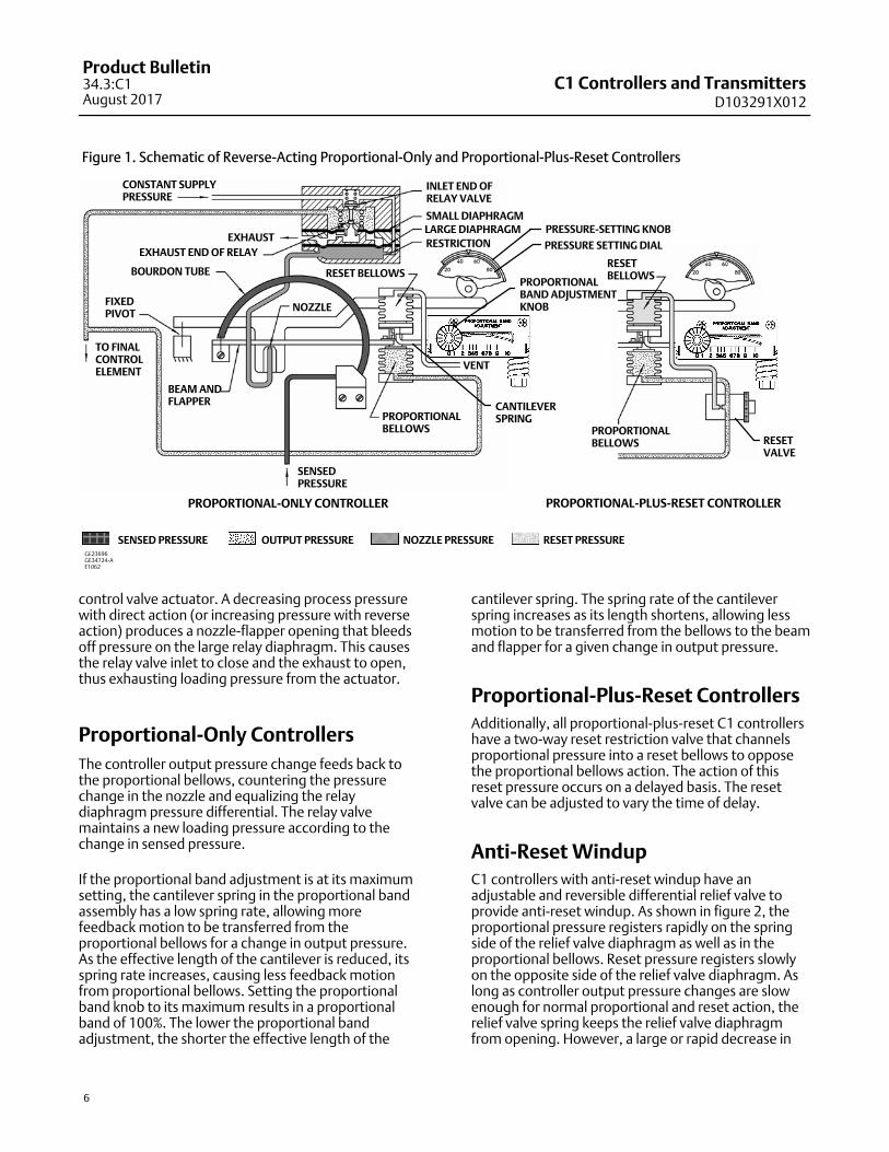
Figure 1. Schematic of Reverse-Acting Proportional-Only and Proportional-Plus-Reset Controllers
CONSTANT SUPPLY PRESSURE
EXHAUST
EXHAUST END OF RELAY
BOURDON TUBE
FIXEDPIVOT
BEAM ANDFLAPPER
NOZZLE
VENT
INLET END OFRELAY VALVE
SMALL DIAPHRAGMLARGE DIAPHRAGM
TO FINALCONTROLELEMENT
SENSEDPRESSURE
RESTRICTION
PROPORTIONAL-PLUS-RESET CONTROLLERPROPORTIONAL-ONLY CONTROLLER
GE23696GE34724-AE1062
PROPORTIONALBELLOWS
RESET BELLOWS
SENSED PRESSURE OUTPUT PRESSURE NOZZLE PRESSURE RESET PRESSURE
CANTILEVERSPRING
RESETVALVE
RESETBELLOWS
PRESSURE SETTING DIAL
PRESSURE-SETTING KNOB
PROPORTIONALBELLOWS
PROPORTIONALBAND ADJUSTMENTKNOB
control valve actuator. A decreasing process pressurewith direct action (or increasing pressure with reverseaction) produces a nozzle-flapper opening that bleedsoff pressure on the large relay diaphragm. This causesthe relay valve inlet to close and the exhaust to open,thus exhausting loading pressure from the actuator.
Proportional-Only Controllers
The controller output pressure change feeds back tothe proportional bellows, countering the pressurechange in the nozzle and equalizing the relaydiaphragm pressure differential. The relay valvemaintains a new loading pressure according to thechange in sensed pressure.
If the proportional band adjustment is at its maximumsetting, the cantilever spring in the proportional bandassembly has a low spring rate, allowing morefeedback motion to be transferred from theproportional bellows for a change in output pressure.As the effective length of the cantilever is reduced, itsspring rate increases, causing less feedback motionfrom proportional bellows. Setting the proportionalband knob to its maximum results in a proportionalband of 100%. The lower the proportional bandadjustment, the shorter the effective length of the
cantilever spring. The spring rate of the cantileverspring increases as its length shortens, allowing lessmotion to be transferred from the bellows to the beamand flapper for a given change in output pressure.
Proportional-Plus-Reset Controllers
Additionally, all proportional-plus-reset C1 controllershave a two-way reset restriction valve that channelsproportional pressure into a reset bellows to opposethe proportional bellows action. The action of thisreset pressure occurs on a delayed basis. The resetvalve can be adjusted to vary the time of delay.
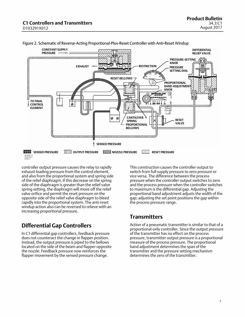
Anti-Reset Windup
C1 controllers with anti-reset windup have anadjustable and reversible differential relief valve toprovide anti-reset windup. As shown in figure 2, theproportional pressure registers rapidly on the springside of the relief valve diaphragm as well as in theproportional bellows. Reset pressure registers slowlyon the opposite side of the relief valve diaphragm. Aslong as controller output pressure changes are slowenough for normal proportional and reset action, therelief valve spring keeps the relief valve diaphragmfrom opening. However, a large or rapid decrease in
C1 Controllers and TransmittersD103291X012
Product Bulletin34.3:C1
August 2017
7
Figure 2. Schematic of Reverse-Acting Proportional-Plus-Reset Controller with Anti-Reset Windup
CONSTANT SUPPLYPRESSURE
TO FINALCONTROLELEMENT
EXHAUST
RESET BELLOWS
RESTRICTION
RESETVALVE
GE23697-AGE34724-AE1063-1
SENSED PRESSURE
PROPORTIONAL BELLOWS
SENSED PRESSURE OUTPUT PRESSURE NOZZLE PRESSURE RESET PRESSURE
DIFFERENTIALRELIEF VALVE
CANTILEVERSPRING
PRESSURESETTING DIAL
PROPORTIONALBAND ADJUSTMENTKNOB
PRESSURE-SETTINGKNOB
controller output pressure causes the relay to rapidlyexhaust loading pressure from the control element,and also from the proportional system and spring sideof the relief diaphragm. If this decrease on the springside of the diaphragm is greater than the relief valvespring setting, the diaphragm will move off the reliefvalve orifice and permit the reset pressure on theopposite side of the relief valve diaphragm to bleedrapidly into the proportional system. The anti-resetwindup action also can be reversed to relieve with anincreasing proportional pressure.
Differential Gap Controllers
In C1 differential gap controllers, feedback pressuredoes not counteract the change in flapper position.Instead, the output pressure is piped to the bellowslocated on the side of the beam and flapper oppositethe nozzle. Feedback pressure now reinforces theflapper movement by the sensed pressure change.
This construction causes the controller output toswitch from full supply pressure to zero pressure orvice versa. The difference between the processpressure when the controller output switches to zeroand the process pressure when the controller switchesto maximum is the differential gap. Adjusting theproportional band adjustment adjusts the width of thegap; adjusting the set point positions the gap withinthe process pressure range.
Transmitters
Action of a pneumatic transmitter is similar to that of aproportional-only controller. Since the output pressureof the transmitter has no effect on the processpressure, transmitter output pressure is a proportionalmeasure of the process pressure. The proportionalband adjustment determines the span of thetransmitter and the pressure setting mechanismdetermines the zero of the transmitter.
C1 Controllers and TransmittersD103291X012
Product Bulletin34.3:C1August 2017
8
Figure 3. Conversion from Reverse to Direct Action or Proportional to Differential Gap
PROPORTIONALTUBING
DIRECT ACTINGREVERSE ACTING
REVERSING BLOCK/NOZZLE
PROPORTIONALBAND ASSEMBLY
PROPORTIONALBAND ASSEMBLY
PROPORTIONAL-ONLY CONTROLLER OR TRANSMITTER
PROPORTIONALTUBING
REVERSING BLOCK/NOZZLE
TO CHANGE ACTION OF THE CONTROLLER, REPOSITION THE PROPORTIONAL TUBING, REVERSING BLOCK/NOZZLE AND PROPORTIONAL BAND ASSEMBLY AS SHOWN ABOVE
RELAY TUBING RELAY TUBINGBELLOWS
DIRECT ACTINGPOSITION
REVERSINGACTING
POSITION
BELLOWS
FLAPPER/SCREWFLAPPER/SCREW
REVERSE ACTINGPOSITION
REVERSING BLOCK
PROPORTIONAL BANDASSEMBLY
DIRECT ACTINGREVERSE ACTING
GE34724-B
RELAY TUBING
DIRECT ACTINGPOSITION
PROPORTIONAL TUBING
PROPORTIONALBAND ASSEMBLY
DIFFERENTIAL-GAP CONTROLLER
FLAPPER/SCREW
REVERSING BLOCK
FLAPPER/SCREW
PROPORTIONAL TUBING
RELAY TUBING
BELLOWS
BELLOWS
GE28263-B
Construction Features
Rugged Service Capability
The case and cover are made of weather resistant,die-cast aluminum. Stainless steel tubing and fittingmaterials provide the capability for operation inammonia and similar corrosive service conditions.Optional materials for relay diaphragms and other softparts permit operation at ambient temperatures up to93�C (200�F).
Low-Pressure PrecisionBellows sensing constructions provide better accuracyin low-pressure, vacuum, or compound ranges. Twosensing bellows are used where an important variableis the difference between two sensed pressures.
Conversion From Proportional ToDifferential Gap ControlThe C1 controller can be configured to providedifferential gap (on-off control) rather thanproportional control. The proportional bellows isconnected so that feedback pressure pushes the beam
C1 Controllers and TransmittersD103291X012
Product Bulletin34.3:C1
August 2017
9
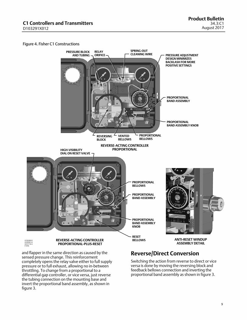
Figure 4. Fisher C1 Constructions
PRESSURE BLOCKAND TUBING
RELAYORIFICE
SPRING-OUTCLEANING WIRE PRESSURE ADJUSTMENT
DESIGN MINIMIZESBACKLASH FOR MOREPOSITIVE SETTINGS
REVERSINGBLOCK
VENTEDBELLOWS
PROPORTIONALBELLOWS
REVERSE-ACTING CONTROLLERPROPORTIONALHIGH-VISIBILITY
DIAL ON RESET VALVE
PROPORTIONALBELLOWS
RESETBELLOWSREVERSE-ACTING CONTROLLER
PROPORTIONAL-PLUS-RESET
ANTI-RESET WINDUPASSEMBLY DETAIL
GE28280-BGE28281-BGE31718-AE1056
PROPORTIONALBAND ASSEMBLY
PROPORTIONALBAND ASSEMBLY KNOB
PROPORTIONALBAND ASSEMBLY
PROPORTIONALBAND ASSEMBLYKNOB
and flapper in the same direction as caused by thesensed pressure change. This reinforcementcompletely opens the relay valve either to full supplypressure or to full exhaust, allowing no in-betweenthrottling. To change from a proportional to adifferential gap controller, or vice versa, just reversethe tubing connection on the mounting base andinvert the proportional band assembly, as shown infigure 3.
Reverse/Direct Conversion
Switching the action from reverse to direct or viceversa is done by moving the reversing block andfeedback bellows connection and inverting theproportional band assembly as shown in figure 3.
C1 Controllers and TransmittersD103291X012
Product Bulletin34.3:C1August 2017
10
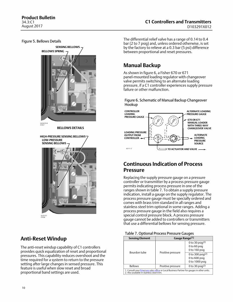
Figure 5. Bellows Details
BELLOWS DETAILS
SENSING BELLOWS
BELLOWS SPRING
GE35157E1058
GE34727-BE1057
HIGH-PRESSURE SENSING BELLOWSLOW-PRESSURESENSING BELLOWS
Anti-Reset Windup
The anti-reset windup capability of C1 controllersprovides quick equalization of reset and proportionalpressures. This capability reduces overshoot and thetime required for a system to return to the pressuresetting after large changes in sensed pressure. Thisfeature is useful when slow reset and broadproportional band settings are used.
The differential relief valve has a range of 0.14 to 0.4bar (2 to 7 psig) and, unless ordered otherwise, is setby the factory to relieve at a 0.3 bar (5 psi) differencebetween proportional and reset pressures.
Manual Backup
As shown in figure 6, a Fisher 670 or 671panel-mounted loading regulator with changeovervalve permits switching to an alternate loadingpressure, if a C1 controller experiences supply pressurefailure or other malfunction.
Figure 6. Schematic of Manual Backup ChangeoverHookup
CONTROLLERLOADINGPRESSURE GAUGE
LOADING PRESSUREOUTPUT FROMCONTROLLER
ALTERNATE LOADINGPRESSURE GAUGE
670 OR 671 MANUAL LOADERWITH THREE-WAYCHANGEOVER VALVE
ALTERNATELOADINGPRESSURESOURCE
TO ACTUATOR AND VALVEA2111-2
Continuous Indication of ProcessPressure
Replacing the supply pressure gauge on a pressurecontroller or transmitter by a process pressure gaugepermits indicating process pressure in one of theranges shown in table 7. To obtain a supply pressureindication, install a gauge on the supply regulator. Theprocess pressure gauge must be specially ordered andcomes with brass trim standard in all ranges andstainless steel trim optional in some ranges. Adding aprocess pressure gauge in the field also requires aspecial control pressure block. A process pressuregauge cannot be added to controllers or transmittersthat use a differential bellows for sensing pressure.
Table 7. Optional Process Pressure GaugesSensing Element Gauge Range(1)
Bourdon tube Positive pressure
0 to 30 psig(2)
0 to 60 psig
0 to 160 psig
0 to 300 psig(2)
0 to 600 psig
0 to 1000 psig
Bellows Positive pressure 0 to 30 psig(2)
1. Consult your Emerson sales office or Local Business Partner for gauges in other units.2. Also available in stainless steel trim.
C1 Controllers and TransmittersD103291X012
Product Bulletin34.3:C1
August 2017
11
Bourdon Tube Protection
All Bourdon tube constructions are available with oneor both of the following protective devices:
� Barrier Protector for Corrosive or Clogging ProcessFluids—A sealed and fluid-filled barrier (described inFisher product bulletin 39:025, D200057X012) maybe installed between the process and the Bourdontube. The barrier fluid transmits sensed pressure ona one-to-one basis into the Bourdon tube.
� Travel Stop for Bourdon Tube—The stop limitsBourdon tube overtravel when momentary surgesin the sensed pressure exceed the Bourdon tuberating. Although it does not permit accurate controlor transmission of a pressure higher than the upperrange limit listed in table 2, this stop does permitBourdon tube overpressuring to the maximumstatic pressure shown in table 2 without damage.
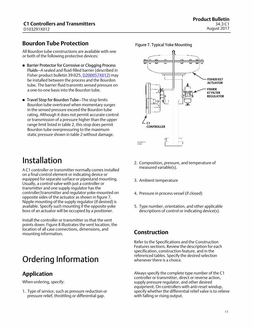
InstallationA C1 controller or transmitter normally comes installedon a final control element or indicating device orequipped for separate surface or pipestand mounting.Usually, a control valve with just a controller ortransmitter and one supply regulator has thecontroller/transmitter and regulator yoke-mounted onopposite sides of the actuator as shown in figure 7.Nipple mounting of the supply regulator (if desired) isavailable. Specify such mounting if the opposite yokeboss of an actuator will be occupied by a positioner.
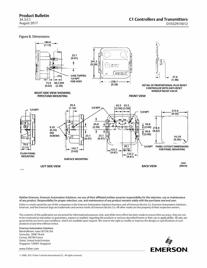
Install the controller or transmitter so that the ventpoints down. Figure 8 illustrates the vent location, thelocation of all case connections, dimensions, andmounting information.
Ordering Information
Application
When ordering, specify:
1. Type of service, such as pressure reduction orpressure relief, throttling or differential gap.
Figure 7. Typical Yoke Mounting
C1CONTROLLER
FISHER 657ACTUATOR
FISHER67 FILTERREGULATOR
GE33947-AE1086
2. Composition, pressure, and temperature ofmeasured variable(s).
3. Ambient temperature
4. Pressure in process vessel (if closed)
5. Type number, orientation, and other applicabledescriptions of control or indicating device(s).
Construction
Refer to the Specifications and the ConstructionFeatures sections. Review the description for eachspecification, construction feature, and in thereferenced tables. Specify the desired selectionwhenever there is a choice.
Always specify the complete type number of the C1controller or transmitter, direct or reverse action,supply pressure regulator, and other desiredequipment. On controllers with anti-reset windup,specify whether the differential relief valve is to relievewith falling or rising output.
C1 Controllers and TransmittersD103291X012
Product Bulletin34.3:C1August 2017
12
Figure 8. Dimensions
37.6(1.48)
241.3(9.50)
23.1(0.91)
180.8(7.12)
15.9(0.62)
60.3 DIA(2.38)
1/4 NPT
1/4 NPT
1/4 NPT
CASE TAPPED1/4 NPTFOR VENT
DETAIL OF PROPORTIONAL-PLUS-RESETCONTROLLER WITH ANTI-RESET
WINDUP RELIEF VALVE
PANEL CUTOUT DIMENSIONSFOR PANEL MOUNTING
RIGHT SIDE VIEW SHOWINGPIPESTAND MOUNTING
LEFT SIDE VIEW BACK VIEW
FRONT VIEW
1/4 NPT
238.1(9.38)
63.5(2.50)
63.5(2.50)
FLUSH PANELMOUNTING
SURFACE MOUNTING
65.8(2.59)
142.7(5.62)
79.4(3.12)
6.35(0.25)DIASCREWS
29.4(1.16)
122.2(4.81)
69.1(2.72)
122.2(4.81)
14.3 R(0.56)
215.9(8.50)
218.9(8.62)50.8
(2.00)
50.8(2.00)
23.1(0.97)
23.1(0.97)
mm(INCH)
E1053
Emerson Automation Solutions Marshalltown, Iowa 50158 USASorocaba, 18087 BrazilCernay, 68700 FranceDubai, United Arab EmiratesSingapore 128461 Singapore
www.Fisher.com
The contents of this publication are presented for informational purposes only, and while every effort has been made to ensure their accuracy, they are notto be construed as warranties or guarantees, express or implied, regarding the products or services described herein or their use or applicability. All sales aregoverned by our terms and conditions, which are available upon request. We reserve the right to modify or improve the designs or specifications of suchproducts at any time without notice.
� 2008, 2017 Fisher Controls International LLC. All rights reserved.
Fisher is a mark owned by one of the companies in the Emerson Automation Solutions business unit of Emerson Electric Co. Emerson Automation Solutions,Emerson, and the Emerson logo are trademarks and service marks of Emerson Electric Co. All other marks are the property of their respective owners.
Neither Emerson, Emerson Automation Solutions, nor any of their affiliated entities assumes responsibility for the selection, use or maintenanceof any product. Responsibility for proper selection, use, and maintenance of any product remains solely with the purchaser and end user.