Embed Size (px)
Citation preview

www.Fisher.com
Fisher™ Control-Disk™ Rotary ValveThe Fisher Control-Disk rotary valve offers excellentthrottling performance. An equal percentage flowcharacteristic provides an improved throttling rangecomparable to that of a segmented ball valve. Thisimproved capability allows you to control closer to thetarget set point, regardless of process disturbances,which results in a reduction in process variability.
The valve body meets PN 10 through PN 40, CL150,and CL300 ratings. Face-to-face dimensions meet EN 558, API 609, and MSS-SP68 standards. Linecentering clips provide for versatility to mount andalign the same wafer style valve body in differentpiping configurations (ASME and EN ratings).
The Control-Disk rotary valve features aneccentrically-mounted disk with either soft or metalseal, providing capability for enhanced shutoff. Theinterchangeable sealing technology allows for thesame valve body to accept both soft and metal seals.
Control-Disk ValveFeatures� Equal percentage flow characteristic— An equal
percentage flow characteristic provides animproved throttling range comparable to that of asegmented ball valve. This improved capabilityallows you to control closer to the target set point,regardless of process disturbances, which results ina reduction in process variability.
� Global Standards— The valve meets API, ASME, andEN standards, making it suitable for use in all worldareas.
� PEEK/PTFE bearing as standard— The PTFE-linedPEEK bearing is a low friction, low wear bearing. Itallows the valve to operate under high pressuredrops for a high cycle life while maintaining lowtorque. The “drop-in” bearing design enables fast,easy maintenance.
DOUBLE FLANGED STYLE(NPS 3 through NPS 12)
X1426
W9418-2 LUGGED STYLE(NPS 3 through NPS 12)
� Lower Operating Torques— The equal percentagedisk reduces operating torque at peak angles of diskopening.
� Spline-ended Shaft— The splined shaft with clampedlever and single-pivot linkage reduces lost motionbetween the actuator and the valve shaft.
Control-Disk ValveD103297X012
Product Bulletin51.3:Control-Disk
July 2018

Control-Disk ValveD103297X012
Product Bulletin51.3:Control-DiskJuly 2018
2
� Improved shaft-disk pinning— The improvedexpansion pin system ensures there is a positive,durable connection between disk and shaft. Thisconnection reduces backlash and wear in the drivesystem, optimizing long-term performance. It alsomakes disassembly for maintenance quick andsimple with no need for special tools.
� New Spring-Loaded Shaft— The spring in theoutboard shaft provides support to the drive trainand disk, enabling the shaft to be installed in bothhorizontal and vertical orientations with nodetriment to performance or cycle life. Thiscomplements the ability to mount the actuator onthe left- or right-hand side, enabling access for anyinstallation.
� Excellent Emissions Capabilities— The optionalENVIRO-SEAL� packing systems, are designed withvery smooth shaft surfaces and live-loading toprovide improved sealing, guiding, and loadingforce transmission. The seal of the ENVIRO-SEALsystem can control emissions to below 100 ppm(parts per million).
� Sour Service Capability— Trim and bolting materialsare available for applications involving sour liquidsand gases. These constructions comply with NACEMR0175-2002, MR0103, and MR0175 / ISO 15156.
� Field-Reversible Valve Action— The actuator/valveassembly action can be converted frompush-down-to-open to push-down-to-close, or viceversa, without additional parts.
� Easy Installation— Line-centering clips engage theline flange bolts to simplify installation and providefor centering of wafer-style valves in the pipeline.End connections are compatible with EN and ASMEstandards.
� Excellent Shutoff— Both the metal and soft sealrings have pressure-assisting sealing action thatensures tight shutoff regardless of pressure drop.
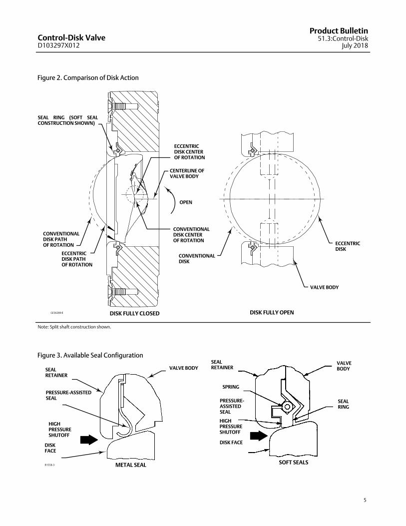
� Long Seal Life— The opening and closing path of theeccentric disk minimizes disk contact with the sealring, thereby reducing seal wear, undue friction,and seating torque requirements. See figure 2.
� Reliable Flange Gasketing Surface— The sealretainer screws and retention clips are outside thegasket surface of the seal retainer. Spiral-wound orflat-sheet gaskets can be installed between theuninterrupted seal retainer face and the pipelineflange.
� Integral Shaft-to-Valve Body Bonding— Standardvalve construction includes conductive packing toprovide electrical bonding for hazardous areaapplications.
� Powder paint as standard— The Emerson powderpaint finish offers an excellent corrosion-resistantfinish to all steel parts.
� High Temperature Capability— The valve willoperate at elevated temperatures, with theappropriate trim components.
� Shaft Retention— Redundant shaft retentionprovides added protection. The packing follower,anti-blowout ring, and shaft groove interact to holdthe shaft securely in the valve body (see figure 1).
� Travel Indication— Additional travel indication canbe achieved by using the indication line on theshaft, along with the disk position markings on thepacking follower (see figure 4).
Table of ContentsControl-Disk Valve Features 1. . . . . . . . . . . . . . . . . . . . Control-Disk Valve Specifications and Materials
of Construction 3. . . . . . . . . . . . . . . . . . . . . . . . . . . .

Control-Disk ValveD103297X012
Product Bulletin51.3:Control-Disk
July 2018
3
Control-Disk Valve Specifications and Materials ofConstructionTable 1. Fisher Control-Disk Valve Specifications
Specifications EN ASME
Valve Body Size DN 50, 80, 100, 150, 200, 250, and 300 NPS 2, 3, 4, 6, 8, 10, and 12
Pressure Rating PN 10 to 40 per EN 12516-1 CL150 / 300 per ASME B16.34 (CL150-600 for NPS 2)
Valve Body Materials
EN 1.0619 steel WCC steel
EN 1.4409 stainless steel CF3M (316L) stainless steel
LCC LCC
CW2M(1) CW2M(1)
M35-2(2) M35-2
Disk Materials
PTFE or RPTFE(4) Seal
EN 1.4409 stainless steel CF3M stainless steel
CW2M CW2M
M35-2 M35-2
Metal or UHMWPE(3)
SealChrome-plated EN 1.4409 Stainless Steel Chrome-plated CF3M Stainless Steel
End Connections Mates with raised-face flanges per EN 1092-1 Mates with raised-face flanges per ASME B16.5
Valve Body Style Lugged with tapped or through holes, Double-Flange with through holes, and Wafer (for select sizes)
Face-to-Face Dimensions Meets MSS SP68, API 609, and EN 558 standards
ShutoffPTFE, RPTFE, or UHMWPE seal ring - Class VI per ANSI/FCI 70-2 and IEC 60534-4
S31600 (316 SST) seal ring - Class IV per ANSI/FCI 70-2 and IEC 60534-4
Flow Coefficients See Fisher Catalog 12
Flow Direction Standard (forward flow) is with the seal retainer facing upstream; reverse flow is permissible for soft seals only
Flow Characteristic Equal percentage
Disk Rotation Counterclockwise to open (when viewed from actuator side of valve body) through 90 degrees of disk rotation
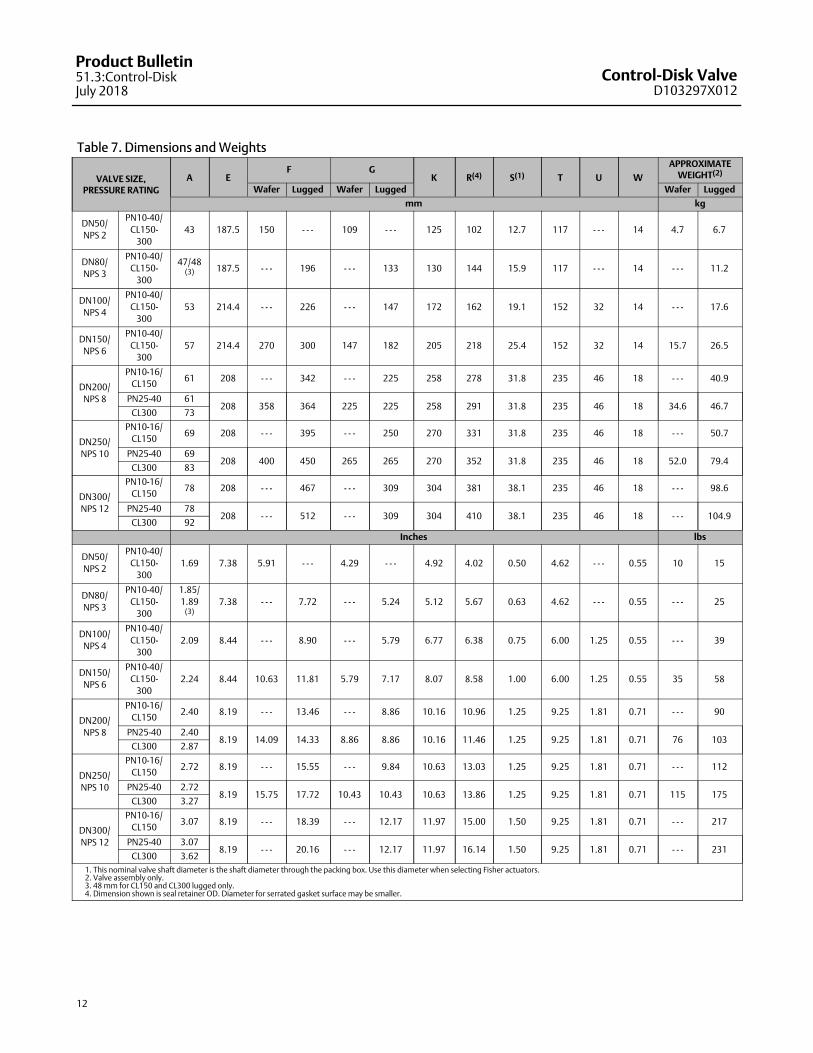
Shaft Diameters and Approximate Weights See table 7
1. This material is not listed in EN 12516-1 or ASME B16.34. See figure 6 for pressure/temperature ratings.2. This material is not listed in EN 12516-1. See figure 6 for pressure/temperature ratings.3. UHMWPE stands for ultra high molecular weight polyethylene.4. RPTFE is a reinforced PTFE seal.
Table 2. Materials (Other Valve Components)Component Material
Shafts and Pins S17400 (17-4PH) stainless steel, S20910 (XM-19) stainless steel, N10276, N05500
Anti-blowout Ring N07718
Seal PTFE, RPTFE, or UHMWPE with S31600 (316 stainless steel) or R30003 spring. Metal seal is 316 stainless steel with graphite gaskets
Bearings PEEK/PTFE, R30006 (Alloy 6), S31600 Nitride
Packing PTFE/carbon-filled PTFE (standard), graphite die-molded ribbon, ENVIRO-SEAL PTFE packing, ENVIRO-SEAL graphite packing
Follower Spring N07718 with carbon-filled PEEK or S31600 spring seats
Bolting B8M Class 2, B7M, N05500, N07718
Nuts 8M, 2HM, N04400, N10276
Table 3. Trim Combinations with Standard Construction MaterialsValve Body Material Shaft Material Disk Material Bearings Seal Material
1.0619 & WCC S17400 H1075
1.4409 & CF3M PEEK/PTFE PTFE or RPTFE
1.4409 & CF3M Chrome-PlatedPEEK/PTFE UHMWPE or Metal
Alloy 6 or S31600 Nitride Metal
LCC S17400 H1075 1.4409 & CF3M PEEK/PTFE PTFE
1.4409 & CF3M S20910
1.4409 & CF3M PEEK/PTFE PTFE or RPTFE
1.4409 & CF3M Chrome-PlatedPEEK/PTFE UHMWPE or Metal
Alloy 6 or S31600 Nitride Metal
CW2M N10276 CW2M PEEK/PTFE PTFE or RPTFE
M35-2 N05500 M35-2 PEEK/PTFE PTFE or RPTFE
Control-Disk ValveD103297X012
Product Bulletin51.3:Control-DiskJuly 2018
4
Figure 1. Typical Fisher Control-Disk Valve Construction Detail
GE36289-C
SOFT SEAL METAL SEAL
DISK
SEAL RETAINER
VALVE BODY
SEAL RING
SEAL RETAINER
DISK
DRIVE SHAFTFOLLOWERSHAFT
EXPANSION PINAND TAPER PIN
BEARING
ANTI-BLOWOUTRING
SEAL RING
Note: Split shaft construction shown.
Control-Disk ValveD103297X012
Product Bulletin51.3:Control-Disk
July 2018
5
Figure 2. Comparison of Disk Action
DISK FULLY CLOSED DISK FULLY OPEN
VALVE BODY
ECCENTRICDISK
CONVENTIONALDISK
OPEN
ECCENTRICDISK CENTEROF ROTATION
CONVENTIONALDISK CENTEROF ROTATION
CENTERLINE OFVALVE BODY
SEAL RING (SOFT SEALCONSTRUCTION SHOWN)
ECCENTRICDISK PATHOF ROTATION
CONVENTIONALDISK PATHOF ROTATION
GE36289-C
Note: Split shaft construction shown.
Figure 3. Available Seal Configuration
SOFT SEALS
SPRING
PRESSURE-ASSISTEDSEAL
HIGHPRESSURESHUTOFF
DISK FACE
VALVEBODY
SEALRING
SEAL RETAINER
PRESSURE-ASSISTEDSEAL
HIGH PRESSURESHUTOFF
DISKFACE
VALVE BODY
B1558-3 METAL SEAL
SEAL RETAINER

Control-Disk ValveD103297X012
Product Bulletin51.3:Control-DiskJuly 2018
6
Figure 4. Travel Indication
GE26389_C
Table 4. Material Temperature CapabilitiesMATERIAL TEMPERATURE LIMITS
PN FLANGES
Valve Body Shaft Bearing Lining and Jacket Seal Packing �C �F
1.0619 Steel S17400 or S20910 PEEK / PTFE PTFE or RPTFE PTFE or Graphite –10 to 232 14 to 450
UHMWPE PTFE or Graphite –10 to 93 14 to 200
Metal or
Flow RingPTFE –10 to 232 14 to 450
Graphite –10 to 260 14 to 500
R30006 (Alloy 6) or S31600 Nitride Metal or
Flow Ring
Graphite –10 to 400 14 to 752
LCC S17400 or S20910 PEEK / PTFE PTFE PTFE –46 to 232 –50 to 450
1.4409
Stainless
Steel
S20910 PEEK / PTFE PTFE or RPTFE PTFE or Graphite –46 to 232 -50 to 450
UHMWPE PTFE or Graphite –18 to 93 0 to 200
Metal or
Flow RingPTFE –46 to 232 -50 to 450
Graphite –46 to 260 -50 to 500
R30006 (Alloy 6) or S31600 Nitride Metal or
Flow Ring
Graphite –46 to 500(1) -50 to 932(1)
CW2M N10276 PEEK / PTFE PTFE or RPTFE PTFE –10 to 232 14 to 450
M35-2 N05500 PEEK / PTFE PTFE or RPTFE PTFE –10 to 232 14 to 450
ASME FLANGES
Valve Body Shaft Bearing Lining and Jacket Seal Packing �C �F
WCC steel S17400 or S20910 PEEK / PTFE PTFE or RPTFE PTFE or Graphite –29 to 232 -20 to 450
UHMWPE PTFE or Graphite –18 to 93 0 to 200
Metal or
Flow RingPTFE –29 to 232 -20 to 450
Graphite –29 to 260 -20 to 500
R30006 (Alloy 6) or S31600 Nitride Metal or
Flow Ring
Graphite –29 to 427 -20 to 800
LCC S17400 or S20910 PEEK / PTFE PTFE PTFE –46 to 232 –50 to 450
CF3M
Stainless
Steel
S20910 PEEK / PTFE PTFE or RPTFE PTFE or Graphite –46 to 232 –50 to 450
UHMWPE PTFE or Graphite –18 to 93 0 to 200
Metal or
Flow RingPTFE –46 to 232 –50 to 450
Graphite –46 to 260 –50 to 500
R30006 (Alloy 6) or S31600 Nitride Metal or
Flow Ring
Graphite –46 to 454(1) –50 to 850(1)
CW2M N10276 PEEK / PTFE PTFE or RPTFE PTFE –46 to 232 –50 to 450
M35-2 N05500 PEEK / PTFE PTFE or RPTFE PTFE –46 to 232 –50 to 450
1. For applications exceeding 427�C (800�F), consult your Emerson sales office or Local Business Partner for appropriate high temperature disk edge coating.

Control-Disk ValveD103297X012
Product Bulletin51.3:Control-Disk
July 2018
7
Figure 5. Material Pressure/Temperature Curves

Control-Disk ValveD103297X012
Product Bulletin51.3:Control-DiskJuly 2018
8
Note: CW2M is not listed in EN 12516-1 or ASME B16.34. The PN and CL designations are used only to indicate relative pressure-retaining capabilities. M35-2 is not listed in EN 12516-1. The PN designations are used only to indicate relative pressure-retaining capabilities.
Figure 6. Material Pressure/Temperature Curves
1
2
1
2

Control-Disk ValveD103297X012
Product Bulletin51.3:Control-Disk
July 2018
9
Figure 7. Material Pressure/Temperature Curves
E1140

Control-Disk ValveD103297X012
Product Bulletin51.3:Control-DiskJuly 2018
10
Table 5. Maximum Allowable Shutoff Pressure Drops based on Trim (Seal, Shaft, and Bearings), BarNote: Do not exceed the EN or ASME pressure/temperature rating of the valve or mating flanges.
TRIM TEMPERATURE, �C
DN
50 80 100 150 200 250 300
Bar
PTFE or RPTFE Seal
PEEK/PTFE Bearings
-46 to 65
93
121
149
191
204
232
51.7
48.5
38.6
28.7
13.8
10.3
3.4
51.7
48.5
38.6
28.7
13.8
10.3
3.4
51.7
48.5
38.6
28.7
13.8
10.3
3.4
51.7
48.5
38.6
28.7
13.8
10.3
3.4
51.7
48.5
38.6
28.7
13.8
10.3
3.4
51.7
45.6
38.6
28.7
13.8
10.3
3.4
51.7
46.8
38.6
28.7
13.8
10.3
3.4
UHMWPE Seal
PEEK/PTFE Bearings
-17 to 37
66
93
51.7
38.6
25.9
51.7
38.6
25.9
51.7
38.6
25.9
51.7
38.6
25.9
51.7
38.6
25.9
51.7
38.6
25.9
51.7
38.6
25.9
Metal Seal(1)
Alloy 6 Bearings
-46 to 37
93
149
204
260
316
371
427
454
18.5
17.0
16.0
15.1
14.3
13.8
13.2
12.5
12.1
16.5
15.1
14.2
13.4
12.8
12.3
11.9
11.6
11.5
13.9
12.8
12.0
11.4
10.8
10.3
10.0
9.8
9.7
12.8
11.7
11.0
10.4
9.9
9.5
9.2
9.0
8.9
11.0
10.1
9.4
9.0
8.5
8.2
7.9
7.7
7.7
6.8
6.3
5.9
5.6
5.3
5.1
5.0
4.8
4.8
7.0
6.5
6.1
5.7
5.4
5.2
5.0
5.0
4.9
Metal Seal(1)
S31600/Nitride
Bearings
-46 to 37
93
149
204
260
316
371
427
454
19.5
19.3
17.0
15.9
14.5
13.8
13.2
12.5
12.1
28.2
28.0
25.4
24.3
22.9
22.1
21.5
20.7
20.3
26.1
26.0
23.7
22.7
21.4
20.8
20.2
19.5
19.2
20.8
20.6
18.7
17.8
16.8
16.2
15.7
15.2
14.9
31.0
31.0
28.8
26.3
24.6
23.2
22.4
21.8
21.6
15.5
15.4
14.0
13.3
12.5
12.1
11.8
11.4
11.2
8.0
7.9
7.1
6.8
6.3
6.1
5.9
5.6
5.4
Metal Seal(1)
PEEK/PTFE Bearings
-46 to 37
93
149
204
232
260
51.7
51.7
50.3
48.6
47.2
24.7
51.7
51.7
50.3
48.6
47.2
21.9
51.7
51.7
50.3
48.6
46.3
18.5
51.7
51.7
50.3
48.2
42.6
17.0
31.0
31.0
31.0
31.0
31.0
14.6
17.2
17.2
17.2
17.2
17.2
9.1
17.2
17.2
17.2
17.2
17.2
9.4
Flow Ring
PEEK/PTFE Bearings
-46 to 37
93
149
204
232
260
51.7
51.7
50.3
48.6
47.2
24.6
51.7
51.7
50.3
48.6
47.2
21.9
51.7
51.7
50.3
48.6
46.3
18.5
51.7
51.7
50.3
48.1
42.6
17
51.7
51.7
50.3
41.3
36.6
14.6
45.5
37.7
31.7
25.7
22.8
9.1
46.8
38.8
32.6
26.4
23.4
9.3
Flow Ring
S31600/Nitride
Bearings
-46 to 37
93
149
204
260
316
371
427
454
32
31.8
29.5
28.5
27.3
26.6
26.1
25.4
25
34.4
34.4
34.4
34.4
37.5
35.5
34.1
28.9
28.9
34.8
34.6
32.4
31.3
30.1
29.5
28.7
27.9
27.6
28.6
28.5
26.6
25.7
24.8
24.2
23.7
23.2
22.9
31.6
31.6
28.7
26.3
24.6
23.2
22.4
21.7
21.5
20.2
19.7
17.9
16.4
15.3
14.4
13.9
13.5
13.3
13
12.9
12.1
11.7
11.3
11.1
10.8
10.6
10.5
1. Pressure drops shown for metal seals are for forward flow only.

Control-Disk ValveD103297X012
Product Bulletin51.3:Control-Disk
July 2018
11
Table 6. Maximum Allowable Shutoff Pressure Drops based on Trim (Seal, Shaft, and Bearings), PsiNote: Do not exceed the EN or ASME pressure/temperature rating of the valve or mating flanges.
TRIM TEMPERATURE, �F
NPS
2 3 4 6 8 10 12
Psi
PTFE or RPTFE Seal
PEEK/PTFE Bearings
-50 to 150
200
250
300
375
400
450
750
704
560
416
200
150
50
750
704
560
416
200
150
50
750
704
560
416
200
150
50
750
704
560
416
200
150
50
750
704
560
416
200
150
50
750
662
560
416
200
150
50
750
679
560
416
200
150
50
UHMWPE Seal
PEEK/PTFE Bearings
0 to 100
150
200
750
560
375
750
560
375
750
560
375
750
560
375
750
560
375
750
560
375
750
560
375
Metal Seal(1)
Alloy 6 Bearings
-50 to 100
200
300
400
500
600
700
800
850
268
246
232
219
208
200
192
181
176
239
219
206
195
186
178
172
168
167
202
185
174
165
157
150
145
142
141
185
170
160
151
144
138
134
130
129
159
146
137
130
124
119
115
112
111
99
91
86
81
77
74
72
70
69
102
94
88
83
79
76
73
72
71
Metal Seal(1)
S31600/Nitride
Bearings
-50 to 100
200
300
400
500
600
700
800
850
283
280
246
230
211
200
192
181
176
409
406
369
352
332
321
312
300
295
379
377
344
329
311
301
293
283
278
301
299
271
258
243
235
228
220
216
450
450
417
382
357
337
325
316
313
225
223
203
193
182
176
171
165
162
116
115
103
98
91
88
85
81
79
Metal Seal(1)
PEEK/PTFE Bearings
-50 to 100
200
300
400
450
500
750
750
730
705
685
358
750
750
730
705
685
318
750
750
730
705
672
269
750
750
730
699
618
247
450
450
450
450
450
212
250
250
250
250
250
132
250
250
250
250
250
136
Flow Ring
PEEK/PTFE Bearings
-50 to 150
200
300
400
450
500
750
750
730
705
685
358
750
750
730
705
685
318
750
750
730
705
672
269
750
750
730
699
618
247
750
750
730
600
531
212
661
548
461
374
331
132
679
563
474
384
340
136
Flow Ring
S31600/Nitride
Bearings
-50 to 150
200
300
400
500
600
700
800
850
465
462
429
414
397
387
379
369
364
499
499
499
499
545
515
496
420
420
505
502
470
455
438
428
417
405
401
416
414
387
374
360
351
345
337
333
459
459
417
382
357
337
325
316
313
293
287
260
238
222
210
202
196
194
189
188
176
171
165
161
158
155
153
1. Pressure drops shown for metal seals are for forward flow only.
Control-Disk ValveD103297X012
Product Bulletin51.3:Control-DiskJuly 2018
12
Table 7. Dimensions and Weights
VALVE SIZE,PRESSURE RATING
A EF G
K R(4) S(1) T U W
APPROXIMATEWEIGHT(2)
Wafer Lugged Wafer Lugged Wafer Lugged
mm kg
DN50/
NPS 2
PN10-40/
CL150-300
43 187.5 150 - - - 109 - - - 125 102 12.7 117 - - - 14 4.7 6.7
DN80/
NPS 3
PN10-40/
CL150-300
47/48(3) 187.5 - - - 196 - - - 133 130 144 15.9 117 - - - 14 - - - 11.2
DN100/
NPS 4
PN10-40/
CL150-300
53 214.4 - - - 226 - - - 147 172 162 19.1 152 32 14 - - - 17.6
DN150/
NPS 6
PN10-40/
CL150-300
57 214.4 270 300 147 182 205 218 25.4 152 32 14 15.7 26.5
DN200/
NPS 8
PN10-16/
CL15061 208 - - - 342 - - - 225 258 278 31.8 235 46 18 - - - 40.9
PN25-40 61208 358 364 225 225 258 291 31.8 235 46 18 34.6 46.7
CL300 73
DN250/
NPS 10
PN10-16/
CL15069 208 - - - 395 - - - 250 270 331 31.8 235 46 18 - - - 50.7
PN25-40 69208 400 450 265 265 270 352 31.8 235 46 18 52.0 79.4
CL300 83
DN300/
NPS 12
PN10-16/
CL15078 208 - - - 467 - - - 309 304 381 38.1 235 46 18 - - - 98.6
PN25-40 78208 - - - 512 - - - 309 304 410 38.1 235 46 18 - - - 104.9
CL300 92
Inches lbs
DN50/
NPS 2
PN10-40/
CL150-300
1.69 7.38 5.91 - - - 4.29 - - - 4.92 4.02 0.50 4.62 - - - 0.55 10 15
DN80/
NPS 3
PN10-40/
CL150-300
1.85/
1.89(3)
7.38 - - - 7.72 - - - 5.24 5.12 5.67 0.63 4.62 - - - 0.55 - - - 25
DN100/
NPS 4
PN10-40/
CL150-300
2.09 8.44 - - - 8.90 - - - 5.79 6.77 6.38 0.75 6.00 1.25 0.55 - - - 39
DN150/
NPS 6
PN10-40/
CL150-300
2.24 8.44 10.63 11.81 5.79 7.17 8.07 8.58 1.00 6.00 1.25 0.55 35 58
DN200/
NPS 8
PN10-16/
CL1502.40 8.19 - - - 13.46 - - - 8.86 10.16 10.96 1.25 9.25 1.81 0.71 - - - 90
PN25-40 2.408.19 14.09 14.33 8.86 8.86 10.16 11.46 1.25 9.25 1.81 0.71 76 103
CL300 2.87
DN250/
NPS 10
PN10-16/
CL1502.72 8.19 - - - 15.55 - - - 9.84 10.63 13.03 1.25 9.25 1.81 0.71 - - - 112
PN25-40 2.728.19 15.75 17.72 10.43 10.43 10.63 13.86 1.25 9.25 1.81 0.71 115 175
CL300 3.27
DN300/
NPS 12
PN10-16/
CL1503.07 8.19 - - - 18.39 - - - 12.17 11.97 15.00 1.50 9.25 1.81 0.71 - - - 217
PN25-40 3.078.19 - - - 20.16 - - - 12.17 11.97 16.14 1.50 9.25 1.81 0.71 - - - 231
CL300 3.62
1. This nominal valve shaft diameter is the shaft diameter through the packing box. Use this diameter when selecting Fisher actuators.2. Valve assembly only.3. 48 mm for CL150 and CL300 lugged only.4. Dimension shown is seal retainer OD. Diameter for serrated gasket surface may be smaller.

Control-Disk ValveD103297X012
Product Bulletin51.3:Control-Disk
July 2018
13
Table 8. Line Bolting Dimensions
VALVE SIZE
Y
Pressure Rating
CL150 CL300 PN10 PN16 PN25 PN40
DN80 / NPS 3 4X 5/8-11 8X 3/4-10 8X M16X2
DN100 / NPS 4 8X 5/8-11 8X 3/4-10 8X M16X2 8X M20X2.5
DN150 / NPS 6 8X 3/4-10 12X 3/4-10 8X M20X2.5 8X M24X3(1)
DN200 / NPS 8 8X 3/4-10 12X 7/8-9 8X M20X2.5 12X M20X2.5 12X M24X3 12X M27X3(1)
DN250 / NPS 10 12X 7/8-9 16X 1-8 12X M20X2.5 12X M24X3 12X M27X3 12X M30X3.5(1)
DN300 / NPS 12 12X 7/8-9 16X 1-1/8-8 12X M20X2.5 12X M24X3 16X M27X3 16X M30X3.5
1. Not available in single flange with threaded holes.
Figure 8. Dimensions for Fisher Control-Disk Valve, Single Flange AA
T T
W W
U
R
S
F
G K E
Y
Figure 9. Dimensions for Fisher Control-Disk Valve, Wafer Style (limited sizes) A A
U
W
T T
W
S
EKG
R
F

Control-Disk ValveD103297X012
Product Bulletin51.3:Control-DiskJuly 2018
14
Table 9. Dimensions and Weights, Double Flange Valve Body (See Figure 10)
VALVE SIZE,PRESSURE RATING
A BE
F G K R S T U WAPPROX-
IMATEWEIGHTSplined Square
mm kg
DN80/
NPS 3
PN10-16
/CL150114 25.3 187.5 76 190 133 130 144 15.9 117 - - - 14 17.6
PN25-40
/CL300180 25.3 187.5 76 210 133 130 144 15.9 117 - - - 14 29
DN100/
NPS 4
PN10-16
/CL150127 28.5 214.4 103 230 147 172 162 19.1 152 32 14 28.9
PN25-40
/CL300190 28.5 214.4 103 254 147 172 162 19.1 152 32 14 47.8
DN150/
NPS 6
PN10-16
/CL150140 31.7 214.4 108 280 182 205 218 25.4 152 32 14 40.2
PN25-40
/CL300210 31.7 214.4 108 322 182 205 218 25.4 152 32 14 76.4
NPS200/
NPS 8
PN10-16
/CL150152 32.8 208 107 345 225 258 278 31.8 235 46 18 71.3
PN25-40
/CL300230 32.8 208 107 380 225 258 291 31.8 235 46 18 124
DN250/
NPS 10
PN10-16
/CL150165 35.6 208 109 405 250 270 331 31.8 235 46 18 80
PN25-40
/CL300250 35.6 208 109 445 265 270 352 31.8 235 46 18 203
DN300/
NPS 12
PN10-16
/CL150178 41.7 208 114 485 309 304 381 38.1 235 46 18 144
PN25-40
/CL300270 41.7 208 114 520 309 304 410 38.1 235 46 18 275
Inches lbs
DN80/
NPS 3
PN10-16
/CL1504.5 1 7.38 2.99 7.48 5.24 5.12 5.67 0.63 4.62 - - - 0.55 39
PN25-40
/CL3007.1 1 7.38 2.99 8.26 5.24 5.12 5.67 0.63 4.62 - - - 0.55 64
DN100/
NPS 4
PN10-16
/ CL1505 1.12 8.44 4.06 9.05 5.79 6.77 6.38 0.75 6 1.25 0.55 64
PN25-40
/CL3007.5 1.12 8.44 4.06 10 5.79 6.77 6.38 0.75 6 1.25 0.55 105
DN150/
NPS 6
PN10-16
/CL1505.5 1.25 8.44 4.25 11.02 7.17 8.07 8.58 1 6 1.25 0.55 89
PN25-40
/CL3008.3 1.25 8.44 4.25 12.66 7.17 8.07 8.58 1 6 1.25 0.55 168
NPS200/
NPS 8
PN10-16
/CL1506 1.29 8.19 4.21 13.58 8.86 10.16 10.96 1.25 9.25 1.81 0.71 157
PN25-40
/CL3009.1 1.29 8.19 4.21 14.96 8.86 10.16 11.46 1.25 9.25 1.81 0.71 273
DN250/
NPS 10
PN10-16
/CL1506.5 1.4 8.19 4.29 15.94 9.84 10.63 13.03 1.25 9.25 1.81 0.71 176
PN25-40
/CL3009.8 1.4 8.19 4.29 17.52 10.43 10.63 13.86 1.25 9.25 1.81 0.71 448
DN300/
NPS 12
PN10-16
/CL1507 1.64 8.19 4.49 19.09 12.17 11.97 15 1.5 9.25 1.81 0.71 317
PN25-40
/CL30010.6 1.64 8.19 4.49 20.47 12.17 11.97 16.14 1.5 9.25 1.81 0.71 606

Control-Disk ValveD103297X012
Product Bulletin51.3:Control-Disk
July 2018
15
Figure 10. Dimensions for Fisher Control-Disk Valve Double Flange
A
W
A
W
T T
EKG
F
Y
S
R
Control-Disk ValveD103297X012
Product Bulletin51.3:Control-DiskJuly 2018
16
Emerson Automation Solutions Marshalltown, Iowa 50158 USASorocaba, 18087 BrazilCernay, 68700 FranceDubai, United Arab EmiratesSingapore 128461 Singapore
www.Fisher.com
The contents of this publication are presented for informational purposes only, and while every effort has been made to ensure their accuracy, they are notto be construed as warranties or guarantees, express or implied, regarding the products or services described herein or their use or applicability. All sales aregoverned by our terms and conditions, which are available upon request. We reserve the right to modify or improve the designs or specifications of suchproducts at any time without notice.
� 2008, 2018 Fisher Controls International LLC. All rights reserved.
Fisher, Control-Disk, and ENVIRO-SEAL are marks owned by one of the companies in the Emerson Automation Solutions business unit of Emerson ElectricCo. Emerson Automation Solutions, Emerson, and the Emerson logo are trademarks and service marks of Emerson Electric Co. All other marks are theproperty of their respective owners.
Neither Emerson, Emerson Automation Solutions, nor any of their affiliated entities assumes responsibility for the selection, use or maintenanceof any product. Responsibility for proper selection, use, and maintenance of any product remains solely with the purchaser and end user.