Embed Size (px)
Citation preview

Hanson and Steinke 2012 Page 1
FISHERIES MONITORING SYSTEM: CATHERINE CREEK PIT TAG INTERROGATION SYSTEMS
Prepared by:
Kyle C. Hanson, Kurt E. Steinke
U.S. Fish & Wildlife Service
Abernathy Fish Technology Center
1440 Abernathy Creek Rd.
Longview, WA 98632
[email protected], [email protected]
Prepared for:
Richard Rieber
Bureau of Reclamation (BOR)
Pacific Northwest Region
1150 N. Curtis Road, Suite 100
Boise, ID 83706
February 29, 2012

Hanson and Steinke 2012 Page 2
Background
Currently, water is diverted from Catherine Creek, a tributary of the Grande Ronde River
in Union County, Oregon, into a series of canals that are used to supply water for irrigation
purposes. The impact of these water diversions on entrainment of local salmonid stocks, such as
steelhead trout (Oncorhynchus mykiss) and Endangered Species Act (ESA) listed Snake River
spring/summer Chinook salmon (O. tshawytscha), is currently unknown. Increasingly, fish
passage near water diversion structures has been monitored using passive integrated transponder
(PIT) tag interrogation systems to assess entrainment, behavior/movement, and loss/mortality of
fish that have been previously implanted with PIT transmitters. In 2010, Abernathy Fish
Technology Center (AFTC) was requested to construct and install four PIT tag interrogation
systems within the Catherine Creek watershed. The goal of these systems was to provide at least
a 90% detection/recognition rate for PIT-tagged salmon moving through the Catherine Creek
watershed. This report details the construction, site locations, and installation methods for each
PIT tag interrogation system, and a list of equipment delivered (Appendix 1).
Construction Methods and Site Descriptions
Site #1: Johnson
The first PIT tag interrogation system was located on Catherine Creek at N 45.30549º W
117.86732º. The system consisted of six antennas placed end to end that spanned the waterway
in two parallel rows (Fig. 1). Each individual antenna was constructed of a single loop of
Category-6 Ethernet cable encased in a waterproof housing of 4in Schedule 80 poly-vinyl
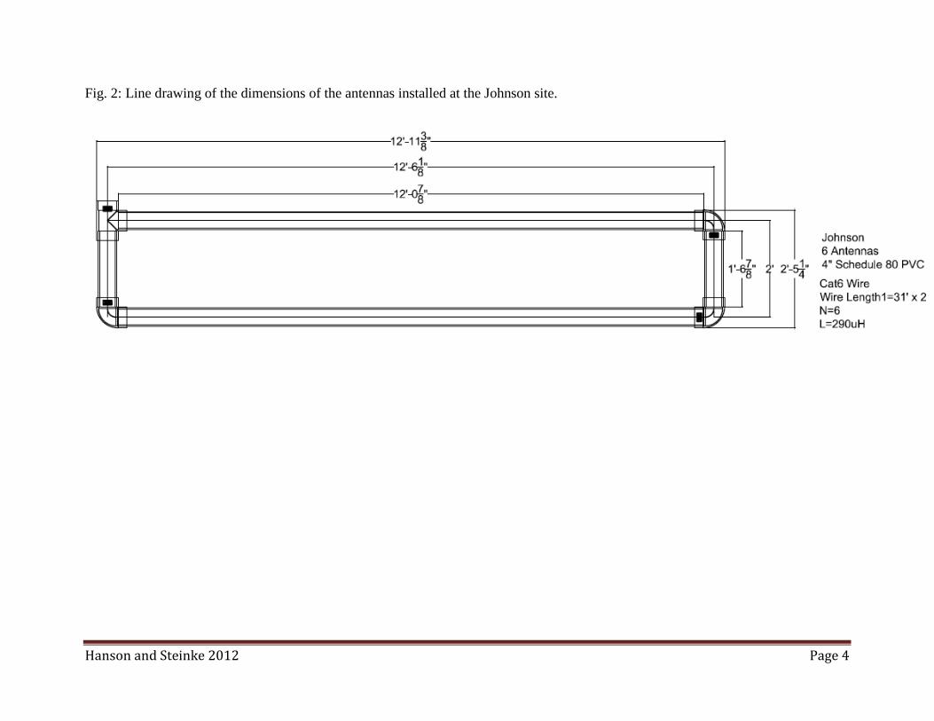
chloride (PVC) pipe. The dimensions of all individual antennas were held constant at 12ft, 11-
3/8in long by 2ft, 5-1/4in wide (Fig. 2). Given the potential for high flows and debris loading,

Hanson and Steinke 2012 Page 3
each antenna was anchored flush with the substrate of the creek in a pass-over configuration
using six screw anchors, one at each corner of the antenna and two in the middle of the longest
pipe segments. Antennas were connected to a Destron Fearing multiplexer (FS 1001M) mounted
in a NEMA box placed on a bluff above the creek via a 53ft cable (12 gauge twinaxial). The
multiplexer was powered by two solar panels (215W 29Vmp) (Fig. 3), and was connected to a
fanless industrial computer (Advantech UNO-1150-S) for data storage (Fig. 4). The data storage
computer was also connected to a cellular modem (Pantech UML290) to allow for automatic
upload of data to the PIT Tag Information System (PTAGIS).
Fig. 1: Antenna configuration of the PIT tag interrogation system installed at the Johnson site.
Hanson and Steinke 2012 Page 4
Fig. 2: Line drawing of the dimensions of the antennas installed at the Johnson site.

Hanson and Steinke 2012 Page 5
Fig. 3: NEMA box and solar panel installation on the bank above the Johnson site. The cabling
at the base of the solar panel frame leads down to antennas that span the waterway.

Hanson and Steinke 2012 Page 6
Fig. 4: Interior view of the electrical components housed within the NEMA box at the Johnson site.

Hanson and Steinke 2012 Page 7
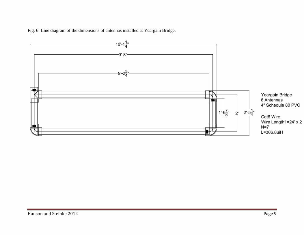
Site #2: Yeargain Bridge
The second PIT tag interrogation system was located just upstream of Yeargain Bridge
on Catherine Creek at N 45.21534º W 117.90383º. The system consisted of six antennas with
the ends of each antenna placed within two feet of each other to maximize coverage of the
waterway in two parallel rows (Fig. 5). Each individual antenna was constructed of a single loop
of Category-6 Ethernet cable encased in a waterproof housing of 4in Schedule 80 PVC pipe.
The dimensions of all individual antennas were held constant at 10ft, 1-1/4in long by 2ft 5-1/4in
wide (Fig. 6). Given the potential for high flows and debris loading, each antenna was anchored
flush with the substrate of the creek in a pass-over configuration using six duckbill anchors
driven into the cobble of the streambed with one at each corner of the antenna and two in the
middle of the longest pipe segments. Antennas were connected to a Destron Fearing Multiplexer
(FS 1001M) mounted in a NEMA box placed on the dry ground above the creek via 80ft cable
(12 gauge twinaxial). The multiplexor was grid powered, modulated through a commercially
available battery backup/surge protector (APC BK500), and was connected to a fanless industrial
computer (Advantech UNO-1150-S) for data storage. The data storage computer was also
connected to a cellular modem (Pantech UML290) to allow for automatic upload of data to
PTAGIS.

Hanson and Steinke 2012 Page 8
Fig. 5: Antenna configuration of the PIT tag interrogation system installed at Yeargain Bridge.
Antennas were spaced approximately two feet apart to maximize coverage of the waterway.
Hanson and Steinke 2012 Page 9
Fig. 6: Line diagram of the dimensions of antennas installed at Yeargain Bridge.

Hanson and Steinke 2012 Page 10
Site #3: Elmer Dam
Of the selected sites, Elmer Dam was considered the most challenging site for installation
of a PIT tag interrogation system due to high water discharge and velocities, extreme flooding,
and the water depth that would need to be covered by the antenna. As such, the AFTC staff
installed two PIT tag interrogation systems at this site using atypical antenna configurations.
One PIT tag interrogation system was located approximately 100 meters upstream of
Elmer Dam on Catherine Creek at 45.36769º W 117.86140º. The system consisted of six
antennas placed end to end spanning the waterway in a single row and mounted along the
substrate of the waterway. Each individual antenna was constructed of a single loop of
Category-6 Ethernet cable encased in a waterproof housing of 4in Schedule 80 PVC pipe. The
dimensions of all individual antennas were held constant at 13ft, 11-1/4in long by 2ft, 5-1/4in
wide (Fig. 7). Given the potential for high flows and debris loading, each antenna was anchored
flush with the substrate of the creek in a pass-over configuration using six screw anchors driven
into the streambed with one at each corner of the antenna and two in the middle of the longest
pipe segments. Antennas were mounted on the substrate of the waterway to detect fish in the
lower portion of the water column. To add additional weight and ensure that the array remained
flush with the substrate of the waterway, additional concrete weights were placed at each corner
and along the length of the individual antennas. Antennas were connected to a Destron Fearing
multiplexer (FS 1001M) mounted in a NEMA box placed on the dry ground above the creek via
99ft cable (12 gauge twinaxial). The multiplexor was powered by grid power modulated through
a commercially available battery backup/surge protector (APC BK500), and was connected to a
fanless industrial computer (Advantech UNO-1150-S) for data storage (Fig. 8). The data storage

Hanson and Steinke 2012 Page 11
computer was also connected to a cellular modem (Pantech UML290) to allow for automatic
upload of data to PTAGIS.

Hanson and Steinke 2012 Page 12
Fig. 7: Line diagram of the dimensions of antennas installed upstream of Elmer Dam on the substrate of the waterway.

Hanson and Steinke 2012 Page 13
Fig. 8: Interior view of the electrical components housed within the NEMA box at Elmer Dam.

Hanson and Steinke 2012 Page 14
The second PIT tag interrogation system was located upstream of Elmer Dam at N
45.21534º W 117.90383º. The system consisted of six antennas placed in a single row and
mounted on plywood boards suspended from a steel cable (1/2” galvanized) that crossed over the
surface of the waterway at a height of 2.6m by a pulley and chain system (Fig. 9). Antennas
were mounted on the surface of the waterway allowing the antennas to detect fish in the upper
portion of the water column as well as deflect and 'ride over' large floating debris. Each
individual antenna was constructed of a single loop of Category-6 Ethernet cable encased in a
waterproof housing of 3in Schedule 40 PVC pipe. The dimensions of all individual antennas
were held constant at 12ft 10in long by 2ft 4in wide (Fig. 10). Antennas were connected to a
Destron Fearing multiplexer (FS 1001M) mounted in a NEMA box placed on the dry ground
above the creek via 92ft cable (12 gauge twinaxial). The multiplexor was powered by grid
power modulated through a commercially available battery backup/surge protector (APC
BK500), and was connected to a fanless industrial computer (Advantech UNO-1150-S) for data
storage (Fig. 11). The data storage computer was also connected to a cellular modem (Pantech
UML290) to allow for automatic upload of data to PTAGIS.

Hanson and Steinke 2012 Page 15
Fig. 9: Side view of the antenna configuration at Elmer Dam with antennas hanging from a steel
cable crossing above the surface of the waterway.

Hanson and Steinke 2012 Page 16
Fig. 10: Line diagram of the dimensions of antennas installed upstream of Elmer Dam and mounted to a steel cable crossing above the
surface of the waterway.

Hanson and Steinke 2012 Page 17
Fig. 11: Interior view of the electrical components housed within the NEMA box at Elmer Dam

Hanson and Steinke 2012 Page 18
Site #4: Gekler Ditch
AFTC staff constructed a PIT tag interrogation system to be installed at the Gekler Ditch
site, however landowner permission for installation was not acquired in time for installation.
The PIT tag interrogation site equipment was instead delivered to Oregon Department of Fish
and Wildlife (ODFW) staff. The system consists of six antennas to be placed end to end
spanning the waterway in two parallel rows. Each individual antenna was constructed of a
double loop of Category-6 Ethernet cable encased in a waterproof housing of 3in Schedule 80
PVC pipe. The dimensions of all individual antennas were held constant at 8ft long by 3ft, 11-
7/8in wide (Fig. 12). Given the low potential for high flows and debris loading, each antenna
was to be configured as a pass through design with only the bottom end of the antenna anchored
to the substrate of the waterway. Antennas were to be connected to a Destron Faering
multiplexor (FS 1001M) mounted in a NEMA box placed on the dry ground above the creek via
40ft cable (12 gauge twinaxial). The multiplexor was to be powered by two solar panels (215W
29Vmp), and was to be connected to a fanless industrial computer (Advantech UNO-1150-S) for
data storage. The data storage computer was also to be connected to a cellular modem (Pantech
UML290) to allow for automatic upload of data to PTAGIS.

Hanson and Steinke 2012 Page 19
Fig. 12: Line diagram of the dimensions of antennas that were to be installed at Gekler Ditch.

Hanson and Steinke 2012 Page 20
Acknowledgements
The findings and conclusions in this article are those of the author and do not necessarily
represent the views of the U.S. Fish and Wildlife Service. Reference to trade names does not
imply endorsement by the U.S. Government. We thank the USFWS, BOR, and ODFW staff
who assisted in the installation of the PIT tag interrogation systems. We thank Scott Favrot
(ODFW) for coordination of site installation and landowner approval.

Hanson and Steinke 2012 Page 21
Appendix 1
Table A.1: Itemized list of all equipment purchased and delivered for the installation of PIT tag interrogation system sites on Catherine Creek.
ITEM QTY Destron Faering FS1001 Multiplexing Transceiver 5 NEMA 4 enclosure, 36"x24"x8" with hasp 3 NEMA 4 enclosure, 36"x30"x16" with hasp 2 Advantech 500Mhz Geode industrial computer with Win XP Embedded and 4Gb CF (.3A @ 24V) 5 500VA, 120V UPS battery back up 3 24V AC/DC linear power supply 3 215W 29Vmp solar panel 4 Aluminum panel solar array frame 2 24V 16A temperature compensated Charge Controller with load disconnect 2 12V 120AH AGM Sealed Lead Acid Rechargeable Battery 4 13' 11-1/4"x2' 5-1/4", single loop, 4" schedule 80 PVC antenna 6 12' 10x"x2' 4" single loop, 3" schedule 40 PVC, antenna on hanging frame 6 8'x3'11-7/8" single loop 3" schedule 80 PVC antenna 6 12' 11-3/8"x2' 5-1/4" single loop 4" schedule 80 PVC antenna 6 10' 1-1/4"x2' 5-1/4" single loop 4" schedule 80 PVC antenna 6 99' Antenna cable 6 92' Antenna cable 6 40' Antenna cable 6 53' Antenna cable 6 80' Antenna cable 6