Embed Size (px)
Citation preview
R&G Racing
Unit 1, Shelley’s Lane, East Worldham, Alton, Hampshire, GU34 3AQ
Tel: +44 (0)1420 89007 Fax: +44 (0)1420 87301 www.rg-racing.com Email: [email protected]
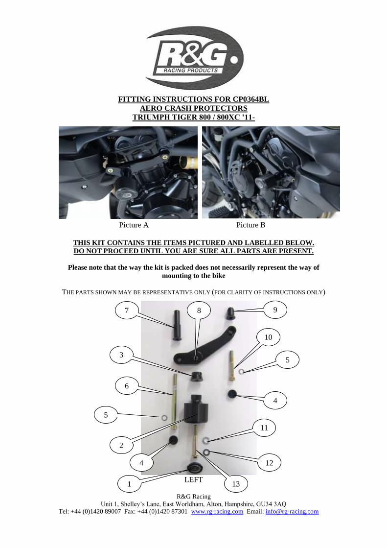
FITTING INSTRUCTIONS FOR CP0364BL
AERO CRASH PROTECTORS
TRIUMPH TIGER 800 / 800XC ’11-
Picture A Picture B
THIS KIT CONTAINS THE ITEMS PICTURED AND LABELLED BELOW.
DO NOT PROCEED UNTIL YOU ARE SURE ALL PARTS ARE PRESENT.
Please note that the way the kit is packed does not necessarily represent the way of
mounting to the bike
THE PARTS SHOWN MAY BE REPRESENTATIVE ONLY (FOR CLARITY OF INSTRUCTIONS ONLY)
LEFT
8
2
3
5
6
5
10
1
7 9
12
11
4
13
4
R&G Racing
Unit 1, Shelley’s Lane, East Worldham, Alton, Hampshire, GU34 3AQ
Tel: +44 (0)1420 89007 Fax: +44 (0)1420 87301 www.rg-racing.com Email: [email protected]
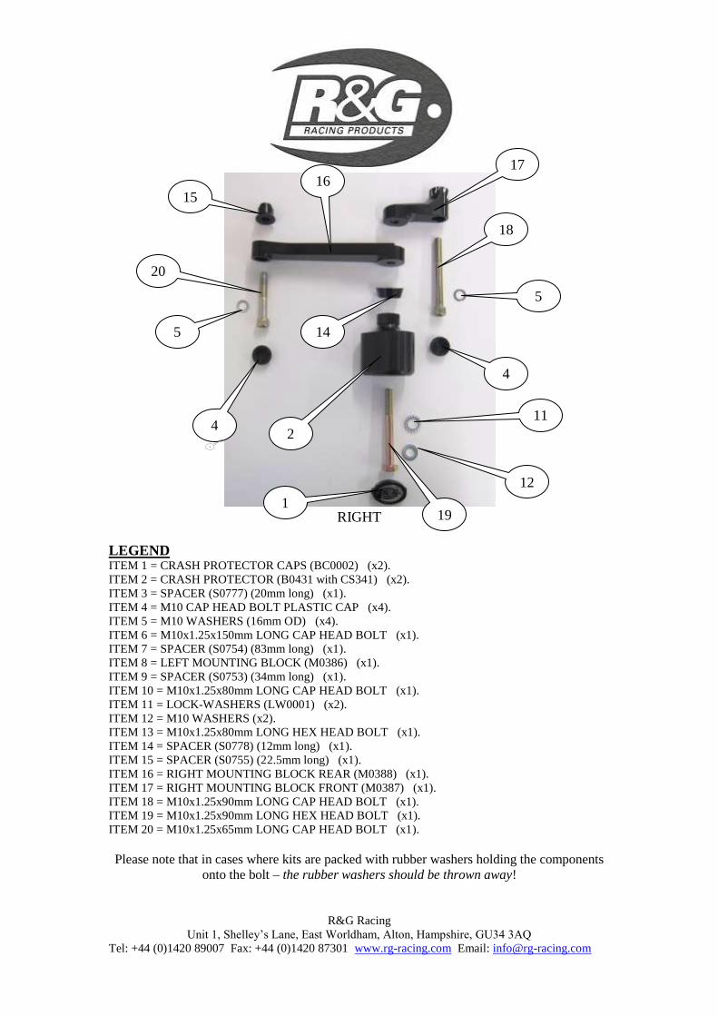
RIGHT
LEGEND ITEM 1 = CRASH PROTECTOR CAPS (BC0002) (x2).
ITEM 2 = CRASH PROTECTOR (B0431 with CS341) (x2).
ITEM 3 = SPACER (S0777) (20mm long) (x1).
ITEM 4 = M10 CAP HEAD BOLT PLASTIC CAP (x4).
ITEM 5 = M10 WASHERS (16mm OD) (x4).
ITEM 6 = M10x1.25x150mm LONG CAP HEAD BOLT (x1).
ITEM 7 = SPACER (S0754) (83mm long) (x1).
ITEM 8 = LEFT MOUNTING BLOCK (M0386) (x1).
ITEM 9 = SPACER (S0753) (34mm long) (x1).
ITEM 10 = M10x1.25x80mm LONG CAP HEAD BOLT (x1).
ITEM 11 = LOCK-WASHERS (LW0001) (x2).
ITEM 12 = M10 WASHERS (x2).
ITEM 13 = M10x1.25x80mm LONG HEX HEAD BOLT (x1).
ITEM 14 = SPACER (S0778) (12mm long) (x1).
ITEM 15 = SPACER (S0755) (22.5mm long) (x1).
ITEM 16 = RIGHT MOUNTING BLOCK REAR (M0388) (x1).
ITEM 17 = RIGHT MOUNTING BLOCK FRONT (M0387) (x1).
ITEM 18 = M10x1.25x90mm LONG CAP HEAD BOLT (x1).
ITEM 19 = M10x1.25x90mm LONG HEX HEAD BOLT (x1).
ITEM 20 = M10x1.25x65mm LONG CAP HEAD BOLT (x1).
Please note that in cases where kits are packed with rubber washers holding the components
onto the bolt – the rubber washers should be thrown away!
1
2
14
4
2
5
20
15 16
17
18
5
4
11
12
19
R&G Racing
Unit 1, Shelley’s Lane, East Worldham, Alton, Hampshire, GU34 3AQ
Tel: +44 (0)1420 89007 Fax: +44 (0)1420 87301 www.rg-racing.com Email: [email protected]
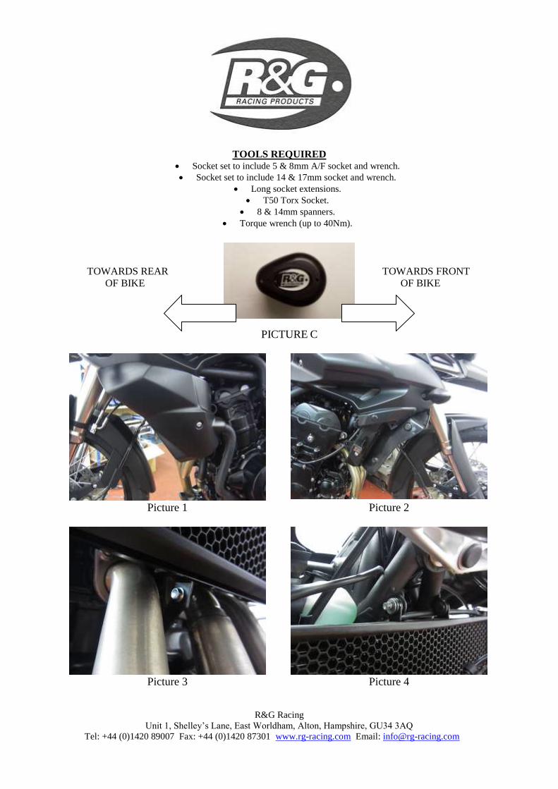
TOOLS REQUIRED
Socket set to include 5 & 8mm A/F socket and wrench.
Socket set to include 14 & 17mm socket and wrench.
Long socket extensions.
T50 Torx Socket.
8 & 14mm spanners.
Torque wrench (up to 40Nm).
TOWARDS REAR TOWARDS FRONT
OF BIKE OF BIKE
PICTURE C
Picture 1 Picture 2
Picture 3 Picture 4
R&G Racing
Unit 1, Shelley’s Lane, East Worldham, Alton, Hampshire, GU34 3AQ
Tel: +44 (0)1420 89007 Fax: +44 (0)1420 87301 www.rg-racing.com Email: [email protected]
Picture 5
Picture 6
Picture 7 Picture 8
Picture 9
Picture 10
R&G Racing
Unit 1, Shelley’s Lane, East Worldham, Alton, Hampshire, GU34 3AQ
Tel: +44 (0)1420 89007 Fax: +44 (0)1420 87301 www.rg-racing.com Email: [email protected]
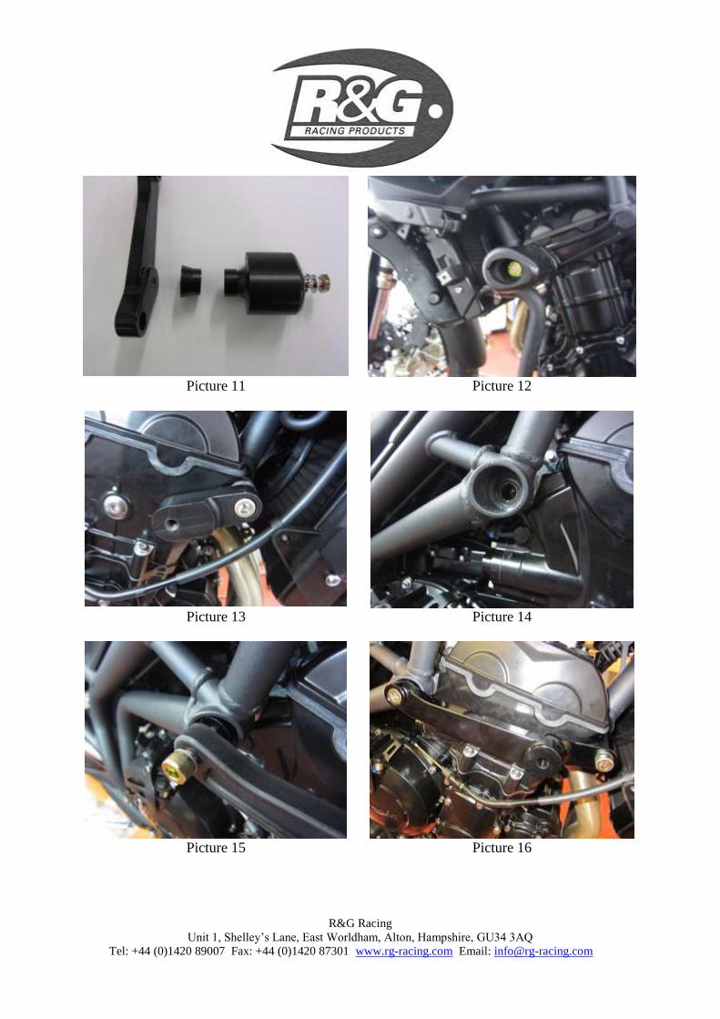
Picture 11 Picture 12
Picture 13
Picture 14
Picture 15 Picture 16
R&G Racing
Unit 1, Shelley’s Lane, East Worldham, Alton, Hampshire, GU34 3AQ
Tel: +44 (0)1420 89007 Fax: +44 (0)1420 87301 www.rg-racing.com Email: [email protected]
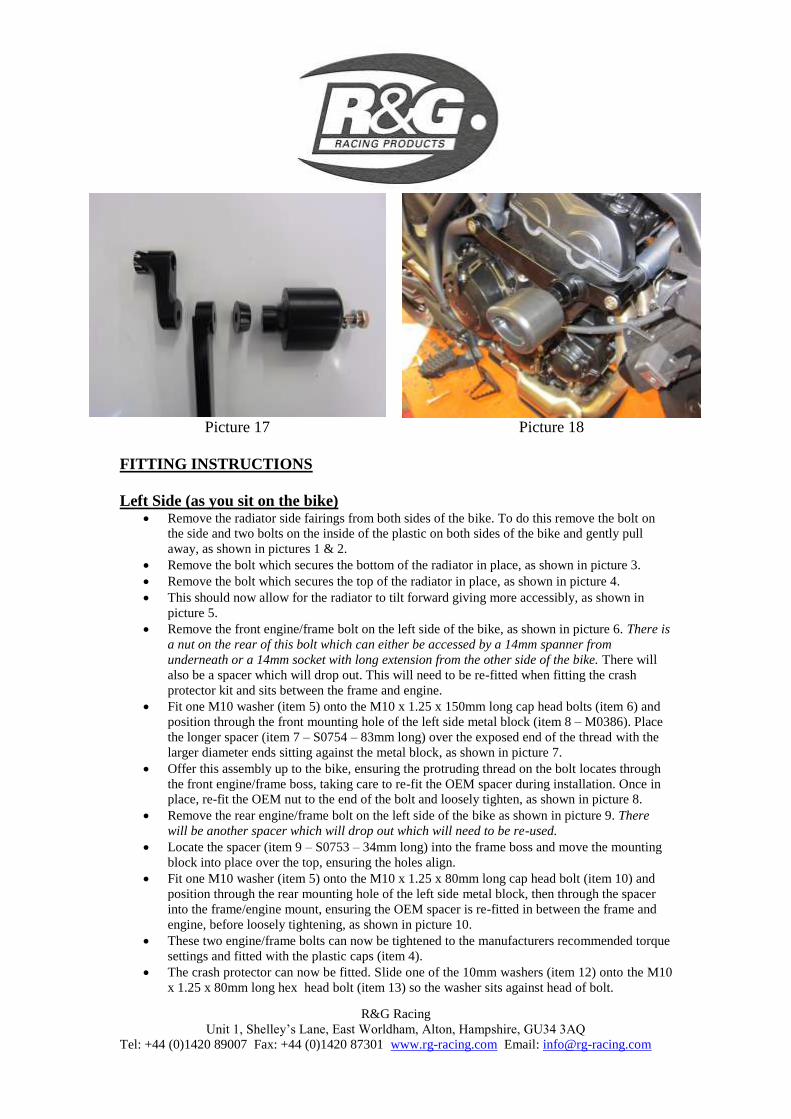
Picture 17 Picture 18
FITTING INSTRUCTIONS
Left Side (as you sit on the bike) Remove the radiator side fairings from both sides of the bike. To do this remove the bolt on
the side and two bolts on the inside of the plastic on both sides of the bike and gently pull
away, as shown in pictures 1 & 2.
Remove the bolt which secures the bottom of the radiator in place, as shown in picture 3.
Remove the bolt which secures the top of the radiator in place, as shown in picture 4.
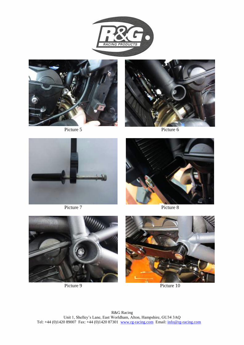
This should now allow for the radiator to tilt forward giving more accessibly, as shown in
picture 5.
Remove the front engine/frame bolt on the left side of the bike, as shown in picture 6. There is
a nut on the rear of this bolt which can either be accessed by a 14mm spanner from
underneath or a 14mm socket with long extension from the other side of the bike. There will
also be a spacer which will drop out. This will need to be re-fitted when fitting the crash
protector kit and sits between the frame and engine.
Fit one M10 washer (item 5) onto the M10 x 1.25 x 150mm long cap head bolts (item 6) and
position through the front mounting hole of the left side metal block (item 8 – M0386). Place
the longer spacer (item 7 – S0754 – 83mm long) over the exposed end of the thread with the
larger diameter ends sitting against the metal block, as shown in picture 7.
Offer this assembly up to the bike, ensuring the protruding thread on the bolt locates through
the front engine/frame boss, taking care to re-fit the OEM spacer during installation. Once in
place, re-fit the OEM nut to the end of the bolt and loosely tighten, as shown in picture 8.
Remove the rear engine/frame bolt on the left side of the bike as shown in picture 9. There
will be another spacer which will drop out which will need to be re-used.
Locate the spacer (item 9 – S0753 – 34mm long) into the frame boss and move the mounting
block into place over the top, ensuring the holes align.
Fit one M10 washer (item 5) onto the M10 x 1.25 x 80mm long cap head bolt (item 10) and
position through the rear mounting hole of the left side metal block, then through the spacer
into the frame/engine mount, ensuring the OEM spacer is re-fitted in between the frame and
engine, before loosely tightening, as shown in picture 10.
These two engine/frame bolts can now be tightened to the manufacturers recommended torque
settings and fitted with the plastic caps (item 4).
The crash protector can now be fitted. Slide one of the 10mm washers (item 12) onto the M10
x 1.25 x 80mm long hex head bolt (item 13) so the washer sits against head of bolt.
R&G Racing
Unit 1, Shelley’s Lane, East Worldham, Alton, Hampshire, GU34 3AQ
Tel: +44 (0)1420 89007 Fax: +44 (0)1420 87301 www.rg-racing.com Email: [email protected]
Slide one serrated locking washer (item 11) over the bolt so it sits against the washer just
fitted.
Next slide the bolt with washers through either crash protector (item 2) so head of bolt and
washers goes into counter-bore in bobbin then over the longer chamfered spacer (item 3 –
S0777 – 20mm long).
Offer the crash protector up to the mounting block and tighten the bolt, as shown in pictures
11 & 12.
Tighten the bolt until you feel some compression from inside the protector using a 17mm
socket and wrench. PLEASE NOTE THE CRASH PROTECTOR MUST BE
POSITIONED AS IN PICTURE ‘C’ WITH BIGGER END TOWARD FRONT OF
BIKE. Turn a little more so that you feel the compression increase slightly. Then apply a
quarter turn. Do not over tighten as damage can occur to the bike. Do not exceed 40nm of
torque.
Right Side (as you sit on the bike) Remove the front engine/frame bolt on the right side of the bike, as shown in picture 13. There
is a nut on the rear of this bolt which can either be accessed by a 14mm socket with long
extension from the other side of the bike.
Fit one M10 washer (item 5) onto the M10 x 1.25 x 90mm long cap head bolt (item 18) and
position through the recessed mounting hole of the right side metal front block (item 17 –
M0387).
Offer this assembly up to the bike, ensuring the protruding thread on the bolt locates through
the front engine/frame boss. Once in place, re-fit the OEM nut to the end of the bolt and
loosely tighten, as shown in picture 13.
Remove the rear engine/frame bolt on the right side of the bike as shown in picture 14.
Fit one M10 washer (item 5) onto the M10 x 1.25 x 65mm long cap head bolt (item 20) and
position through the mounting hole of the right side metal rear block (item 16 – M0388), then
through the remaining spacer (item 15 – S0755 – 22.5mm long) and into the frame/engine
mount, before loosely tightening, as shown in picture 15.
The two blocks can now be aligned on the bike so that the hole on the top block aligns with
the threaded boss on the block behind. There is also a machined recess on the rear of the top
block which will sit around the rear block.
The crash protector can now be fitted. Slide one of the 10mm washers (item 12) onto the M10
x 1.25 x 90mm long hex head bolt (item 19) so the washer sits against head of bolt.
Slide one serrated locking washer (item 11) over the bolt so it sits against the washer just
fitted.
Next slide the bolt with washers through either crash protector (item 2) so head of bolt and
washers goes into counter-bore in bobbin then over the shorter chamfered spacer (item 14 –
S0778 – 12mm long). Offer the crash protector up to the mounting block and tighten the bolt,
as shown in pictures 17 & 18.
Tighten the bolt until you feel some compression from inside the protector using a 17mm
socket and wrench. PLEASE NOTE THE CRASH PROTECTOR MUST BE
POSITIONED AS IN PICTURE ‘C’ WITH BIGGER END TOWARD FRONT OF
BIKE. Turn a little more so that you feel the compression increase slightly. Then apply a
quarter turn. Do not over tighten as damage can occur to the bike. Do not exceed 40nm of
torque.
The two engine/frame bolts can now be tightened to the manufacturers recommended torque
settings and fitted with the plastic caps (item 4).
Re-fit the two bolts that secure the radiator in place.
Re-fit the six bolts which secure the plastic radiator cowling in place.
R&G Racing
Unit 1, Shelley’s Lane, East Worldham, Alton, Hampshire, GU34 3AQ
Tel: +44 (0)1420 89007 Fax: +44 (0)1420 87301 www.rg-racing.com Email: [email protected]
Ensure the fairings are correctly fitted with all bolts fully tightened.
If not already fitted fit bubble stickers into recess of both crash protector caps.
Fit crash protector caps into both crash protectors.
ISSUE 1 09/05/2014 (AR)
Digital copies of these instructions are available to download from www.rg-racing.com
CONSUMER NOTICE
The catalogue description and any exhibition of samples are only broad indications of the Products and R&G may make design changes which do not diminish their performance or visual appeal and supplying them in such state shall conform to the order.
The Buyer acknowledges no representation or warranty (other than as to title) has been given or will apply to the Products other
than those in R&G’s order or confirmation and the Buyer confirms it has chosen the Products as being of merchantable quality
and suitable for its particular purposes. Where R&G fits the Products or undertakes other services it shall exercise reasonable
skill and care and rectify any fault free of charge unless the workmanship has been disturbed. The Buyer is responsible for
ensuring that the warranty on the motorcycle is not affected by the fitting of the Products. On return of any defective Products R&G shall at its option either supply a replacement or refund the purchase money but shall not be liable if the Products have
been modified or used or maintained otherwise than in accordance with R&G’s or manufacturer’s instructions and good
engineering practice or if the defect arises from accident or neglect. Other than identified above and subject to R&G not limiting its liability for causing death and personal injury, it shall not be liable for indirect or consequential loss and otherwise its liability
shall be limited to the amounts paid by the Buyer for the Products or the fitting or service concerned. These terms do not affect
the Buyer’s statutory rights.
R&G RACING RETURNS POLICY (NON-FAULTY GOODS)
Returns must be pre-authorised (if not pre-authorised the return will be rejected). Goods may only be returned direct to us if they
were purchased direct from us (customer must prove if necessary). Otherwise to be returned to original vendor. Goods must be in re-sellable condition, in the opinion of R&G Racing. All returns are subject to a 25% restocking and handling fee (25% of the
gross value exc. P&P – at the prevailing price at time of purchase). The customer must pay any and all carriage charges. No
returns of discontinued products, unless within 14 days of purchase. This policy does not affect your statutory rights and does not refer to faulty goods.
R&G Racing
Unit 1, Shelley’s Lane, East Worldham, Alton, Hampshire, GU34 3AQ
Tel: +44 (0)1420 89007 Fax: +44 (0)1420 87301 www.rg-racing.com Email: [email protected]
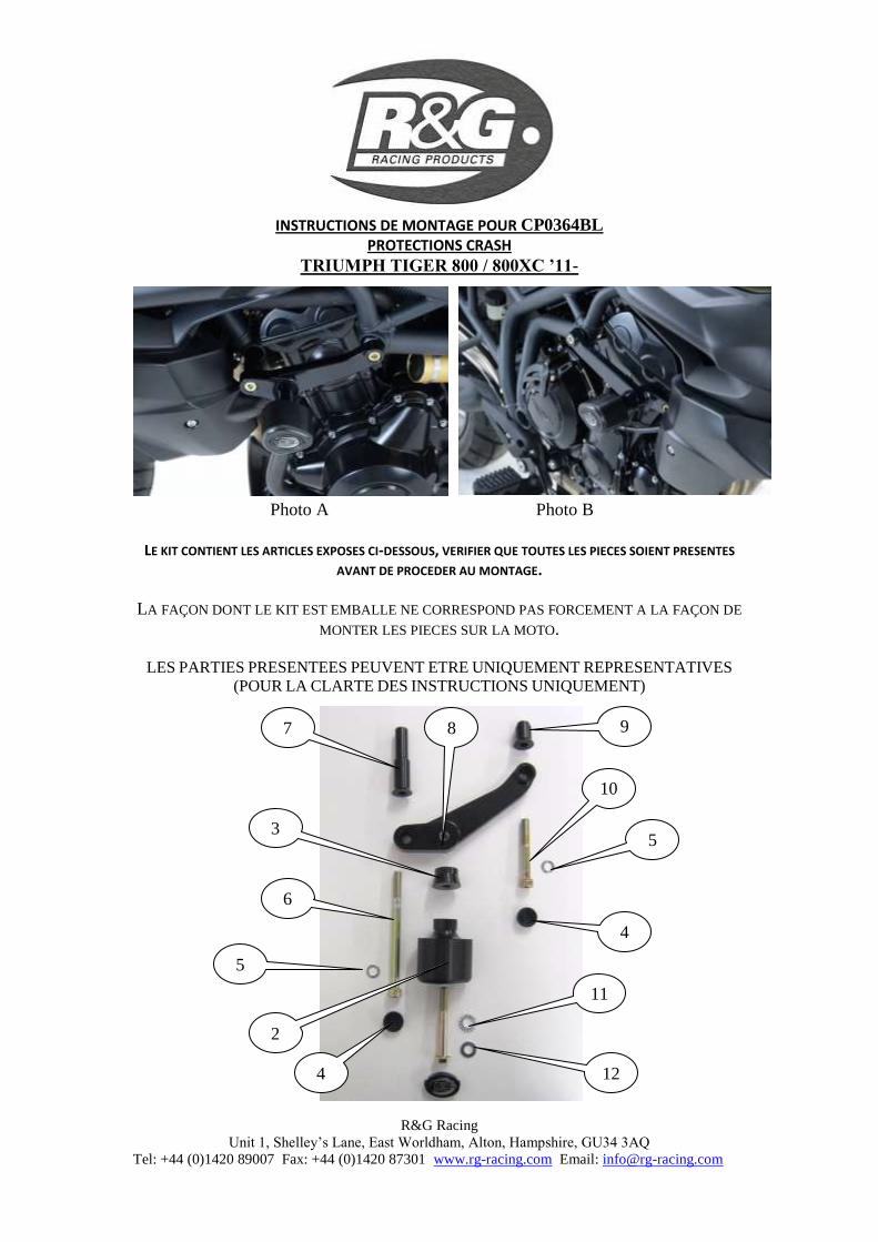
INSTRUCTIONS DE MONTAGE POUR CP0364BL
PROTECTIONS CRASH
TRIUMPH TIGER 800 / 800XC ’11-
Photo A Photo B
LE KIT CONTIENT LES ARTICLES EXPOSES CI-DESSOUS, VERIFIER QUE TOUTES LES PIECES SOIENT PRESENTES
AVANT DE PROCEDER AU MONTAGE.
LA FAÇON DONT LE KIT EST EMBALLE NE CORRESPOND PAS FORCEMENT A LA FAÇON DE
MONTER LES PIECES SUR LA MOTO.
LES PARTIES PRESENTEES PEUVENT ETRE UNIQUEMENT REPRESENTATIVES
(POUR LA CLARTE DES INSTRUCTIONS UNIQUEMENT)
8
2
3
5
6
5
10
7 9
12
11
4
4
R&G Racing
Unit 1, Shelley’s Lane, East Worldham, Alton, Hampshire, GU34 3AQ
Tel: +44 (0)1420 89007 Fax: +44 (0)1420 87301 www.rg-racing.com Email: [email protected]
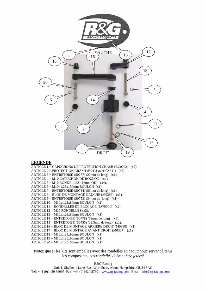
GAUCHE
DROIT
LEGENDE ARTICLE 1 = CAPUCHONS DE PROTECTION CRASH (BC0002) (x2).
ARTICLE 2 = PROTECTION CRASH (B0431 avec CS341) (x2).
ARTICLE 3 = ENTRETOISE (S0777) (20mm de long) (x1).
ARTICLE 4 = M10 CAPUCHON DE BOULON (x4).
ARTICLE 5 = M10 RONDELLES (16mm OD) (x4).
ARTICLE 6 = M10x1.25x150mm BOULON (x1).
ARTICLE 7 = ENTRETOISE (S0754) (83mm de long) (x1).
ARTICLE 8 = BLOC DE MONTAGE GAUCHE (M0386) (x1).
ARTICLE 9 = ENTRETOISE (S0753) (34mm de long) (x1).
ARTICLE 10 = M10x1.25x80mm BOULON (x1).
ARTICLE 11 = RONDELLES DE BLOCAGE (LW0001) (x2).
ARTICLE 12 = M10 RONDELLES (x2).
ARTICLE 13 = M10x1.25x80mm BOULON (x1).
ARTICLE 14 = ENTRETOISE (S0778) (12mm de long) (x1).
ARTICLE 15 = ENTRETOISE (S0755) (22.5mm de long) (x1).
ARTICLE 16 = BLOC DE MONTAGE ARRIERE DROIT (M0388) (x1).
ARTICLE 17 = BLOC DE MONTAGE AVANT DROIT (M0387) (x1).
ARTICLE 18 = M10x1.25x90mm BOULON (x1).
ARTICLE 19 = M10x1.25x90mm BOULON (x1).
ARTICLE 20 = M10x1.25x65mm BOULON (x1).
Notez que si les kits sont emballés avec des rondelles en caoutchouc servant à tenir
les composants, ces rondelles doivent être jetées!
1 13
1
2
14
4
2
5
20
15 16
17
18
5
4
11
12
19
R&G Racing
Unit 1, Shelley’s Lane, East Worldham, Alton, Hampshire, GU34 3AQ
Tel: +44 (0)1420 89007 Fax: +44 (0)1420 87301 www.rg-racing.com Email: [email protected]
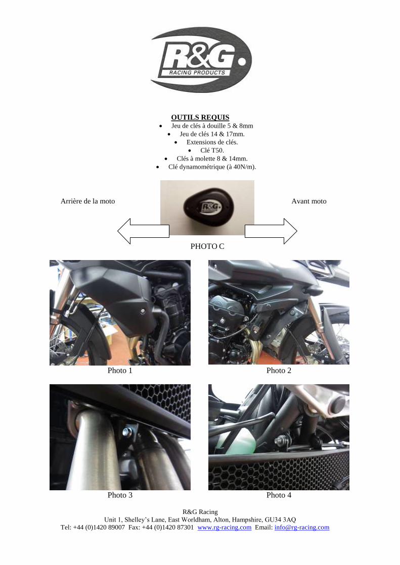
OUTILS REQUIS
Jeu de clés à douille 5 & 8mm
Jeu de clés 14 & 17mm.
Extensions de clés.
Clé T50.
Clés à molette 8 & 14mm.
Clé dynamométrique (à 40N/m).
Arrière de la moto Avant moto
PHOTO C
Photo 1 Photo 2
Photo 3 Photo 4
R&G Racing
Unit 1, Shelley’s Lane, East Worldham, Alton, Hampshire, GU34 3AQ
Tel: +44 (0)1420 89007 Fax: +44 (0)1420 87301 www.rg-racing.com Email: [email protected]
Photo 5
Photo 6
Photo 7 Photo 8
Photo 9
Photo 10

R&G Racing
Unit 1, Shelley’s Lane, East Worldham, Alton, Hampshire, GU34 3AQ
Tel: +44 (0)1420 89007 Fax: +44 (0)1420 87301 www.rg-racing.com Email: [email protected]
Photo 11 Photo 12
Photo 13
Photo 14
Photo 15 Photo 16
R&G Racing
Unit 1, Shelley’s Lane, East Worldham, Alton, Hampshire, GU34 3AQ
Tel: +44 (0)1420 89007 Fax: +44 (0)1420 87301 www.rg-racing.com Email: [email protected]
Photo 17 Photo 18
INSTRUCTIONS DE MONTAGE : Coté gauche (assis sur la moto)
Enlever les carénages de radiateur des 2 cotés de la moto. Pour cela, enlever le boulon sur le coté et les 2 boulons à l’intérieur du plastique des 2 cotés de la moto puis tirer, comme sur les photos 1 & 2.
Enlever le boulon qui fixe le bas du radiateur en place, comme sur la photo3.
Enlever the boulon qui fixe le haut du radiateur en place, comme sur la photo4.
Cela doit permettre au radiateur de basculer vers l’avant pour donne davantage d’accessibilité, comme sur la photo5.
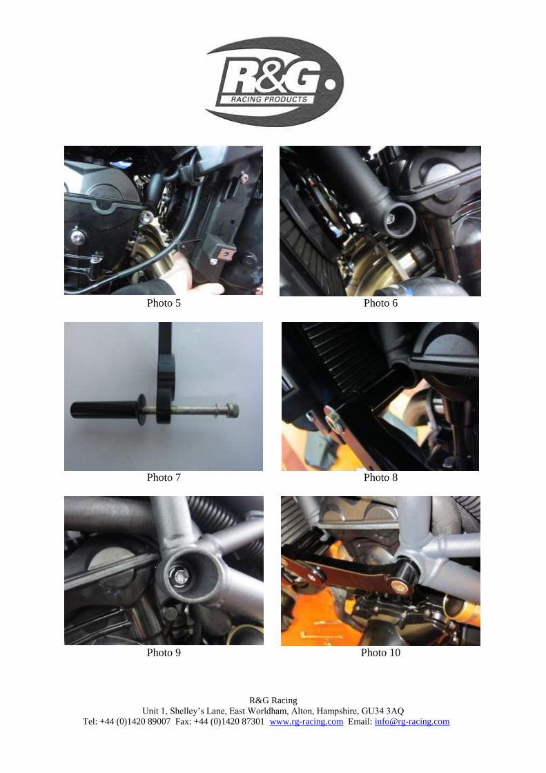
Enlever le boulon avant de cadre/moteur du coté gauche de la moto, comme sur la photo 6. Il y a un écrou à l’arrière du boulon auquel on peut accéder avec une clé de 14mm par le dessous ou une clé de 14mm avec un extension, depuis l’autre coté de la moto. Il y aura aussi une entretoise qui tombera. Elle devra être réutilisée lors de l’installation de la protection crash et se place entre le cadre et le moteur.
Passer une rondelle M10 (article 5) sur le boulon M10 x 1.25 x 150mm (article 6) et positionnez le à travers le trou du support avant du coté gauche du bloc de métal (article 8 – M0386). Placer l’entretoise la plus longue (article 7 – S0754 – 83mm de long) sur l’extrémité du filetage avec les extrémités de diamètre les plus larges contre le bloc de métal, comme sur la photo 7.
Placer l’ensemble sur la moto, en veillant à ce que le filetage dépassant du boulon se place sur le patron de cadre/moteur avant. Ne pas oublier de remettre l’entretoise d’origine pendant le montage. Une fois en place, remettre l’écrou d’origine à l’extrémité du boulon et serrer légèrement, comme sur la photo 8.
Enlever le boulon arrière du cadre/moteur du coté gauche de la moto, comme sur la photo 9. Il y aura une autre entretoise qui tombera, elle devra être réutilisée.
Placer l’entretoise (article 9 – S0753 – 34mm de long) dans le patron de cadre et mettre le bloc de montage en place sur le haut, en veillant à ce que les trous soient bien alignés.
Passer une rondelle M10 (article 5) sur le boulon M10 x 1.25 x 80mm (article 10) et positionnez le à travers le trou de support arrière du coté gauche du bloc de montage, puis à travers l’entretoise dans le support cadre/moteur, en veillant à ce que l’entretoise d’origine
R&G Racing
Unit 1, Shelley’s Lane, East Worldham, Alton, Hampshire, GU34 3AQ
Tel: +44 (0)1420 89007 Fax: +44 (0)1420 87301 www.rg-racing.com Email: [email protected]
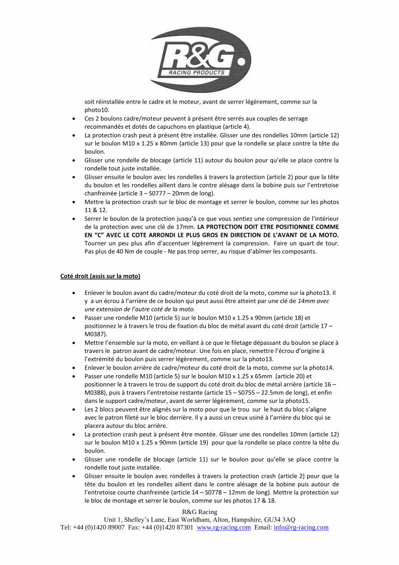
soit réinstallée entre le cadre et le moteur, avant de serrer légèrement, comme sur la photo10.
Ces 2 boulons cadre/moteur peuvent à présent être serrés aux couples de serrage recommandés et dotés de capuchons en plastique (article 4).
La protection crash peut à présent être installée. Glisser une des rondelles 10mm (article 12) sur le boulon M10 x 1.25 x 80mm (article 13) pour que la rondelle se place contre la tête du boulon.
Glisser une rondelle de blocage (article 11) autour du boulon pour qu’elle se place contre la rondelle tout juste installée.
Glisser ensuite le boulon avec les rondelles à travers la protection (article 2) pour que la tête du boulon et les rondelles aillent dans le contre alésage dans la bobine puis sur l’entretoise chanfreinée (article 3 – S0777 – 20mm de long).
Mettre la protection crash sur le bloc de montage et serrer le boulon, comme sur les photos 11 & 12.
Serrer le boulon de la protection jusqu’à ce que vous sentiez une compression de l’intérieur de la protection avec une clé de 17mm. LA PROTECTION DOIT ETRE POSITIONNEE COMME EN “C” AVEC LE COTE ARRONDI LE PLUS GROS EN DIRECTION DE L’AVANT DE LA MOTO. Tourner un peu plus afin d’accentuer légèrement la compression. Faire un quart de tour. Pas plus de 40 Nm de couple - Ne pas trop serrer, au risque d’abîmer les composants.
Coté droit (assis sur la moto)
Enlever le boulon avant du cadre/moteur du coté droit de la moto, comme sur la photo13. Il y a un écrou à l’arrière de ce boulon qui peut aussi être atteint par une clé de 14mm avec une extension de l’autre coté de la moto.
Passer une rondelle M10 (article 5) sur le boulon M10 x 1.25 x 90mm (article 18) et positionnez le à travers le trou de fixation du bloc de métal avant du coté droit (article 17 – M0387).
Mettre l’ensemble sur la moto, en veillant à ce que le filetage dépassant du boulon se place à travers le patron avant de cadre/moteur. Une fois en place, remettre l’écrou d’origine à l’extrémité du boulon puis serrer légèrement, comme sur la photo13.
Enlever le boulon arrière de cadre/moteur du coté droit de la moto, comme sur la photo14.
Passer une rondelle M10 (article 5) sur le boulon M10 x 1.25 x 65mm (article 20) et positionner le à travers le trou de support du coté droit du bloc de métal arrière (article 16 – M0388), puis à travers l’entretoise restante (article 15 – S0755 – 22.5mm de long), et enfin dans le support cadre/moteur, avant de serrer légèrement, comme sur la photo15.
Les 2 blocs peuvent être alignés sur la moto pour que le trou sur le haut du bloc s’aligne avec le patron fileté sur le bloc derrière. Il y a aussi un creux usiné à l’arrière du bloc qui se placera autour du bloc arrière.
La protection crash peut à présent être montée. Glisser une des rondelles 10mm (article 12) sur le boulon M10 x 1.25 x 90mm (article 19) pour que la rondelle se place contre la tête du boulon.
Glisser une rondelle de blocage (article 11) sur le boulon pour qu’elle se place contre la rondelle tout juste installée.
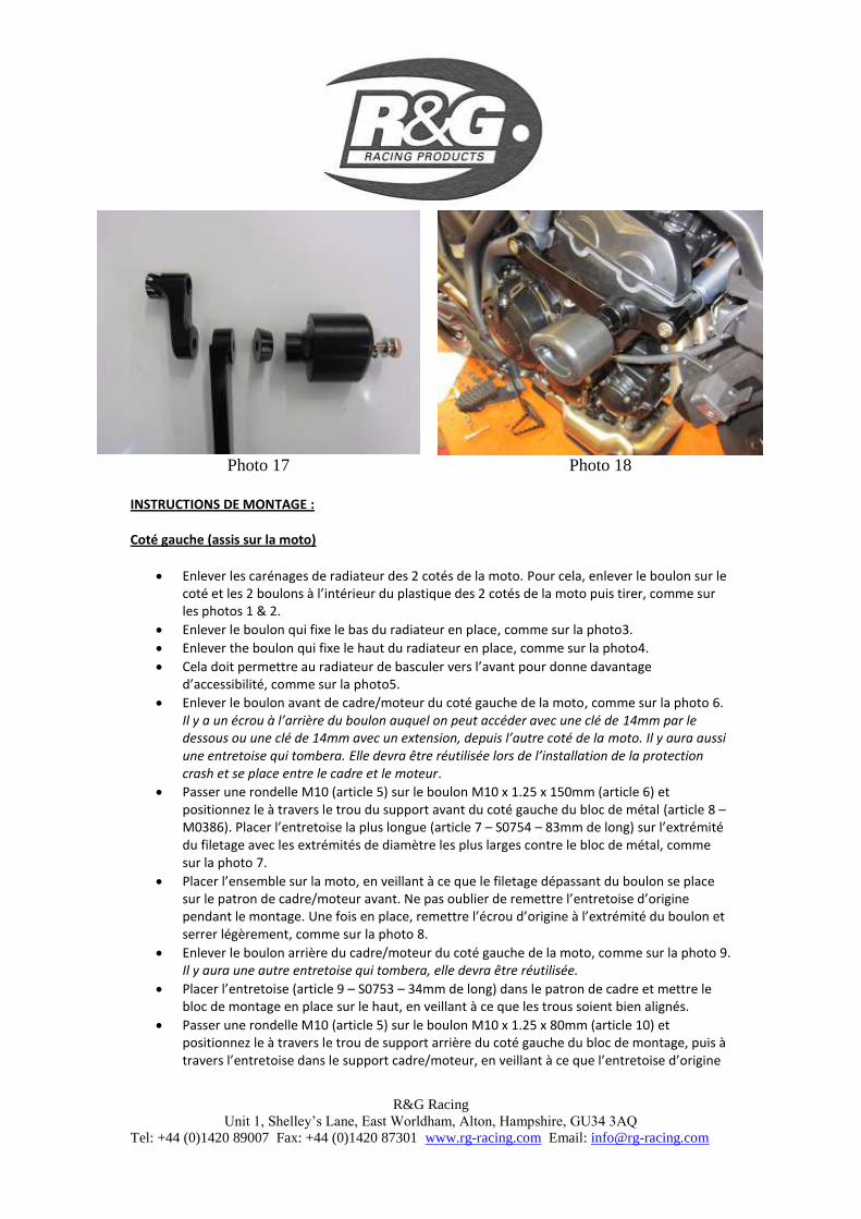
Glisser ensuite le boulon avec rondelles à travers la protection crash (article 2) pour que la tête du boulon et les rondelles aillent dans le contre alésage de la bobine puis autour de l’entretoise courte chanfreinée (article 14 – S0778 – 12mm de long). Mettre la protection sur le bloc de montage et serrer le boulon, comme sur les photos 17 & 18.
R&G Racing
Unit 1, Shelley’s Lane, East Worldham, Alton, Hampshire, GU34 3AQ
Tel: +44 (0)1420 89007 Fax: +44 (0)1420 87301 www.rg-racing.com Email: [email protected]
Serrer le boulon de la protection jusqu’à ce que vous sentiez une compression de l’intérieur de la protection avec une clé de 17mm. LA PROTECTION DOIT ETRE POSITIONNEE COMME EN “C” AVEC LE COTE ARRONDI LE PLUS GROS EN DIRECTION DE L’AVANT DE LA MOTO. Tourner un peu plus afin d’accentuer légèrement la compression. Faire un quart de tour. Pas plus de 40 Nm de couple - Ne pas trop serrer, au risque d’abîmer les composants.
Les 2 boulons moteur/cadre peuvent à présent être serrés aux couples de serrage recommandés puis dotez-les des capuchons en plastic (article 4).
Remettre les 2 boulons qui fixent le radiateur en place.
Remettre les 6 boulons qui fixent la grille de radiateur en place.
Veiller à ce que les carénages soient correctement montés avec tous les boulons complètement serrés.
Si cela n’est pas déjà fait, appliquez les stickers de caoutchouc dans le creux des 2 protections crash.
Mettre les capuchons de protection crash dans les 2 protections crash.
ISSUE 1 09/05/2014 (AR)
Ces instructions sont disponibles au téléchargement sur www.rg-racing.com
CONSUMER NOTICE
The catalogue description and any exhibition of samples are only broad indications of the Products and R&G may make design changes which do not diminish their performance or visual appeal and supplying them in such state shall conform to the order.
The Buyer acknowledges no representation or warranty (other than as to title) has been given or will apply to the Products other
than those in R&G’s order or confirmation and the Buyer confirms it has chosen the Products as being of merchantable quality and suitable for its particular purposes. Where R&G fits the Products or undertakes other services it shall exercise reasonable
skill and care and rectify any fault free of charge unless the workmanship has been disturbed. The Buyer is responsible for ensuring that the warranty on the motorcycle is not affected by the fitting of the Products. On return of any defective Products
R&G shall at its option either supply a replacement or refund the purchase money but shall not be liable if the Products have
been modified or used or maintained otherwise than in accordance with R&G’s or manufacturer’s instructions and good
engineering practice or if the defect arises from accident or neglect. Other than identified above and subject to R&G not limiting
its liability for causing death and personal injury, it shall not be liable for indirect or consequential loss and otherwise its liability
shall be limited to the amounts paid by the Buyer for the Products or the fitting or service concerned. These terms do not affect the Buyer’s statutory rights.
R&G RACING RETURNS POLICY (NON-FAULTY GOODS)
Returns must be pre-authorised (if not pre-authorised the return will be rejected). Goods may only be returned direct to us if they
were purchased direct from us (customer must prove if necessary). Otherwise to be returned to original vendor. Goods must be in re-sellable condition, in the opinion of R&G Racing. All returns are subject to a 25% restocking and handling fee (25% of the
gross value exc. P&P – at the prevailing price at time of purchase). The customer must pay any and all carriage charges. No
returns of discontinued products, unless within 14 days of purchase. This policy does not affect your statutory rights and does not refer to faulty goods.