Embed Size (px)
Citation preview
Five9 Network Systems LLC. X3000 Installation Manual
Document # 000005, V1.0, 07/24/2014 Page 1
Five9NS X3000 Rack Mount Server / Workstation
Installation Manual
Version July 24. 2014: This version supersedes all previous versions.
2012 Five9 Network Systems LLC, 300 Main Street, Suite 12A, East Rochester, NY 14445, USA
All rights reserved.
This product or document is protected by copyright and distributed under licenses restricting its use, copying, distribution, and decompilation.
No part of this product or document may be reproduced in any form by any means without prior written authorization of Five9NS and its
licensors, if any.
Five9 Network Systems LLC. X3000 Installation Manual
Document # 000005, V1.0, 07/24/2014 Page 2
Table of Contents
Section Description Page
1.0 General Information ....................................................................... 3
1.1 Introduction ......................................................................................... 3
1.2 Purpose of the Equipment ................................................................... 3
1.3 Optional Equipment ............................................................................. 3
2.0 Application ...................................................................................... 4
2.1 Introduction .......................................................................................... 4
2.2 Typical Application ................................................................................ 4
3.0 Installation ....................................................................................... 4
3.1 Prior to Installation ................................................................................ 4
3.2 Unpacking and Inspection ..................................................................... 6
3.3 Cautions & Warnings ............................................................................. 6
3.4 Wiring ………………………............................................................................ 7
3.6 Physical Characteristics .......................................................................... 7
3.7 Electrical Characteristics ........................................................................ 8
3.8 Post-Installation Test ............................................................................. 9
4.0 Optional Equipment Installation ....................................................... 9
4.1 Speaker Mounting …………………………………………………………………………….. 9
4.2 IO Card Installation …………………………………………………………………………… 11
Five9 Network Systems LLC. X3000 Installation Manual
Document # 000005, V1.0, 07/24/2014 Page 3
X3000
3U Rack Mount / Workstation
1.0 General Information
1.1 Introduction
This manual contains information for the proper installation of the Five9 Network
Systems, LLC. 3U Rack Mount Server / Workstation, Model No: X3000. Also
included are physical and electrical characteristics of the unit.
1.2 Purpose of the Equipment
1.2.1 Five9NS’s X3000 is a 3U server designed specifically for Entry-level server
and workstation applications. It supports a large range of Intel Xeon x86
E3-1200v3 series processors from dual-core to quad-core, which are
carried as a part of the Intel Embedded IA Extended Life Cycle Support. In
the recommended installation, the unit receives power from an AC power
source and can be either sitting on a table top or in a rack mount,
enabling both workstation or server modes.
1.2.2 It supports Solaris which is the most scalable and secure operating
system. With Solaris, the X3000 server provides fast performance, near-
continual uptime, and the security and reliability required from a mission-
critical system.
1.3 Optional Equipment
An internal 8 ohm speaker with the necessary mounting hardware, as well as the
Five9NS Multi-Function IO card and the required installation cables can be
ordered with the X3000. These components provide convenient solutions for a
variety of IO functionalities such as audio, additional USB ports and additional
Ethernet ports to meet different customer requirements.
Five9 Network Systems LLC. X3000 Installation Manual
Document # 000005, V1.0, 07/24/2014 Page 4
2.0 Application
2.1 Introduction
The X3000 is a 100-240 VAC product that can serve as either a workstation or a
rack mount unit. It contains an Intel motherboard and CPU. Included also in the
unit is a 100 GB Solid State Drive (SSD) storage device
2.2 Typical Application
2.2.1 In cases where a workstation environment is required, the X3000 can be
placed on a table top. Connect a monitor and other required IO
peripherals through the connection ports on the system. When mounting
it sideways, please make sure the system is stable.
NOTE: WHEN USED IN A SIDE-MOUNT CONFIGURATION, THE POWER
SUPPLY SHOULD BE ON THE BOTTOM SIDE.
2.2.2 In cases of rack mount environments, X3000 will be installed above or
below other servers. Specific rack mount instructions apply to the
installation process. Please see section 3 for more details.
3.0 Installation
3.1 Prior to Installation
The X3000 is a simple module to install. Before installation, the following items
should be considered
3.1.1 Careful consideration of the location of the X3000 is necessary. Some of
the items to consider include:
Space to allow adequate airflow
Length of cable runs
Environmental conditions
Access for service repair (if applicable)
Note: Please see detailed instructions for rack mounting in section 3.1.3
Five9 Network Systems LLC. X3000 Installation Manual
Document # 000005, V1.0, 07/24/2014 Page 5
3.1.2 The X3000 shall be installed to conform to the standards designated by
the customer and manufacturer specifications as to the unit location and
type of installation
3.1.3 The following rack mount instructions should be followed
A) Elevated Operating Ambient - If installed in a closed or multi-unit rack
assembly, the operating ambient temperature of the rack environment
may be greater than room ambient. Therefore, consideration should be
given to installing the equipment in an environment compatible with the
maximum ambient temperature (Tma) specified by the manufacturer.
B) Reduced Air Flow - Installation of the equipment in a rack should be
such that the amount of air flow required for safe operation of the
equipment is not compromised.
C) Mechanical Loading - Mounting of the equipment in the rack should be
such that a hazardous condition is not achieved due to uneven
mechanical loading.
D) Circuit Overloading - Consideration should be given to the connection
of the equipment to the supply circuit and the effect that overloading of
the circuits might have on overcurrent protection and supply wiring.
Appropriate consideration of equipment nameplate ratings should be
used when addressing this concern.
E) Reliable Earthing - Reliable earthing of rack-mounted equipment
should be maintained. Particular attention should be given to supply
connections other than direct connections to the branch circuit (e.g. use
of power strips)."
F) System Maintenance - Maintenance and servicing of this product is to
be performed only by trained service personnel who are knowledgeable
on the procedures and hazards associated with this product.
Five9 Network Systems LLC. X3000 Installation Manual
Document # 000005, V1.0, 07/24/2014 Page 6
G) Cautions and Warnings – All caution and warning instructions noted on
the product and in the manual should be followed (see Section 3.3 below
for details).
3.2 Unpacking and Inspection
3.2.1 Carefully open the packaging and remove the X3000. Verify that all
components have been included in the package per the packing list.
Inspect the unit for shipping damage.
3.2.2 If damage has occurred during shipping, a claim should be filed with
Five9NS and an RMA shall be obtained from Five9NS.
3.3 Cautions and Warnings
3.3.1 Do not remove any factory-installed screws
3.3.2 Do not install near heat sources
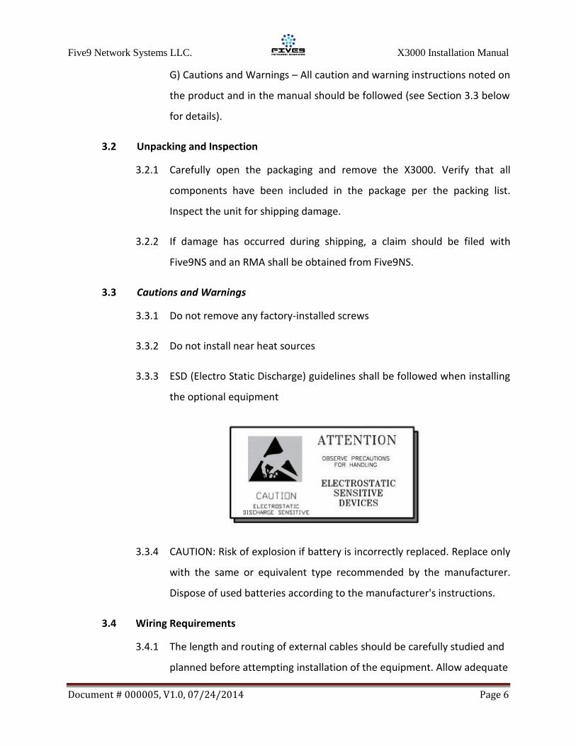
3.3.3 ESD (Electro Static Discharge) guidelines shall be followed when installing
the optional equipment
3.3.4 CAUTION: Risk of explosion if battery is incorrectly replaced. Replace only
with the same or equivalent type recommended by the manufacturer.
Dispose of used batteries according to the manufacturer's instructions.
3.4 Wiring Requirements
3.4.1 The length and routing of external cables should be carefully studied and
planned before attempting installation of the equipment. Allow adequate
Five9 Network Systems LLC. X3000 Installation Manual
Document # 000005, V1.0, 07/24/2014 Page 7
space for installation of cable and connectors. Avoid sharp bends.
3.5 Physical Characteristics
3.5.1 The X3000 shall be located away from heat sources, magnetic fields and
areas with excessive dust.
3.5.2 When using a rack mount, the unit shall be rigidly mounted to its location
using the appropriate hardware
3.5.3 When sitting on a table top, avoid uneven or unstable work surfaces
3.6 Electrical Characteristics
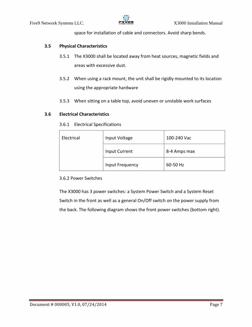
3.6.1 Electrical Specifications
Electrical Input Voltage 100-240 Vac
Input Current 8-4 Amps max
Input Frequency 60-50 Hz
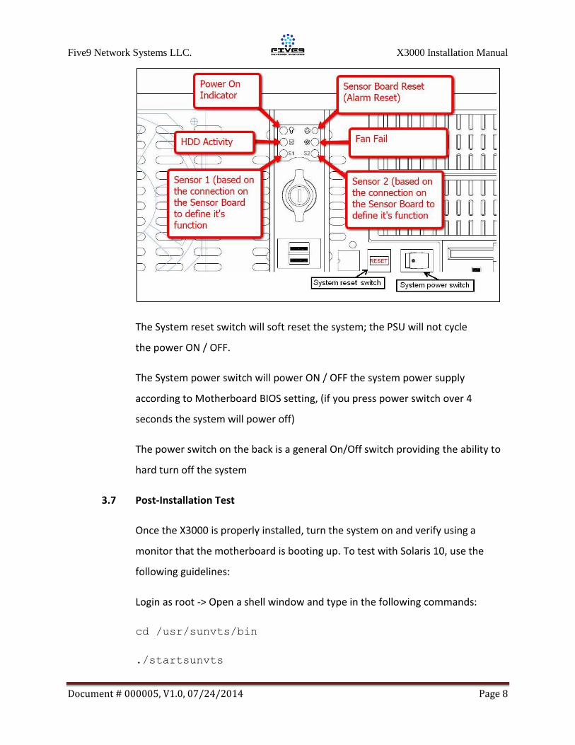
3.6.2 Power Switches
The X3000 has 3 power switches: a System Power Switch and a System Reset
Switch in the front as well as a general On/Off switch on the power supply from
the back. The following diagram shows the front power switches (bottom right).
Five9 Network Systems LLC. X3000 Installation Manual
Document # 000005, V1.0, 07/24/2014 Page 8
The System reset switch will soft reset the system; the PSU will not cycle
the power ON / OFF.
The System power switch will power ON / OFF the system power supply
according to Motherboard BIOS setting, (if you press power switch over 4
seconds the system will power off)
The power switch on the back is a general On/Off switch providing the ability to
hard turn off the system
3.7 Post-Installation Test
Once the X3000 is properly installed, turn the system on and verify using a
monitor that the motherboard is booting up. To test with Solaris 10, use the
following guidelines:
Login as root -> Open a shell window and type in the following commands:
cd /usr/sunvts/bin
./startsunvts
Five9 Network Systems LLC. X3000 Installation Manual
Document # 000005, V1.0, 07/24/2014 Page 9
You will have to choose between different interfaces to run SUNvts with. Choose
the command line option and enter the following commands:
./vts_cmd list_tests
This command lists all the tests to be performed. Make sure all test are enabled.
To enable a certain test use the following: ./vts_cmd enable_test
testname
./vts_cmd set_global_options [Duration of
Testing:60,Verbose:Enable]
This will run the tests for 60 minutes.
./vts_cmd start
This will start the testing. You can stop the tests anytime using: ./vts_cmd
stop. Please refer to the SUNvts user guide for more information.
4.0 Optional Equipment Installation
4.1 Speaker mounting
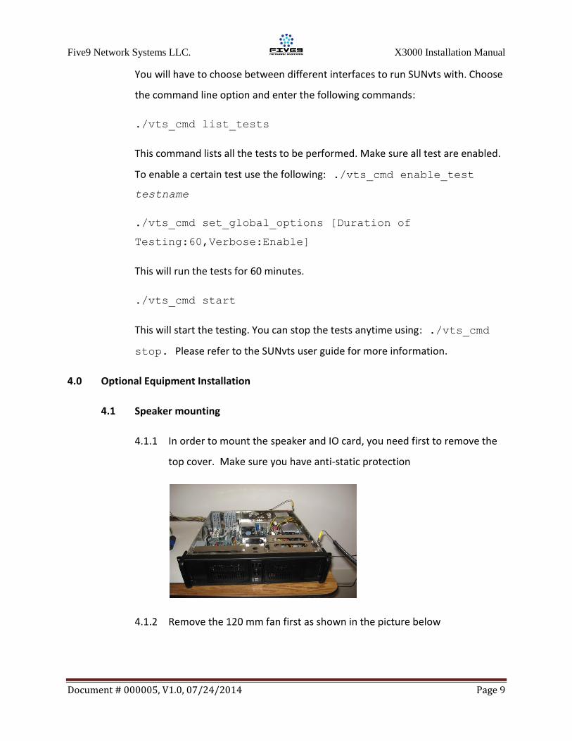
4.1.1 In order to mount the speaker and IO card, you need first to remove the
top cover. Make sure you have anti-static protection
4.1.2 Remove the 120 mm fan first as shown in the picture below
Five9 Network Systems LLC. X3000 Installation Manual
Document # 000005, V1.0, 07/24/2014 Page 10
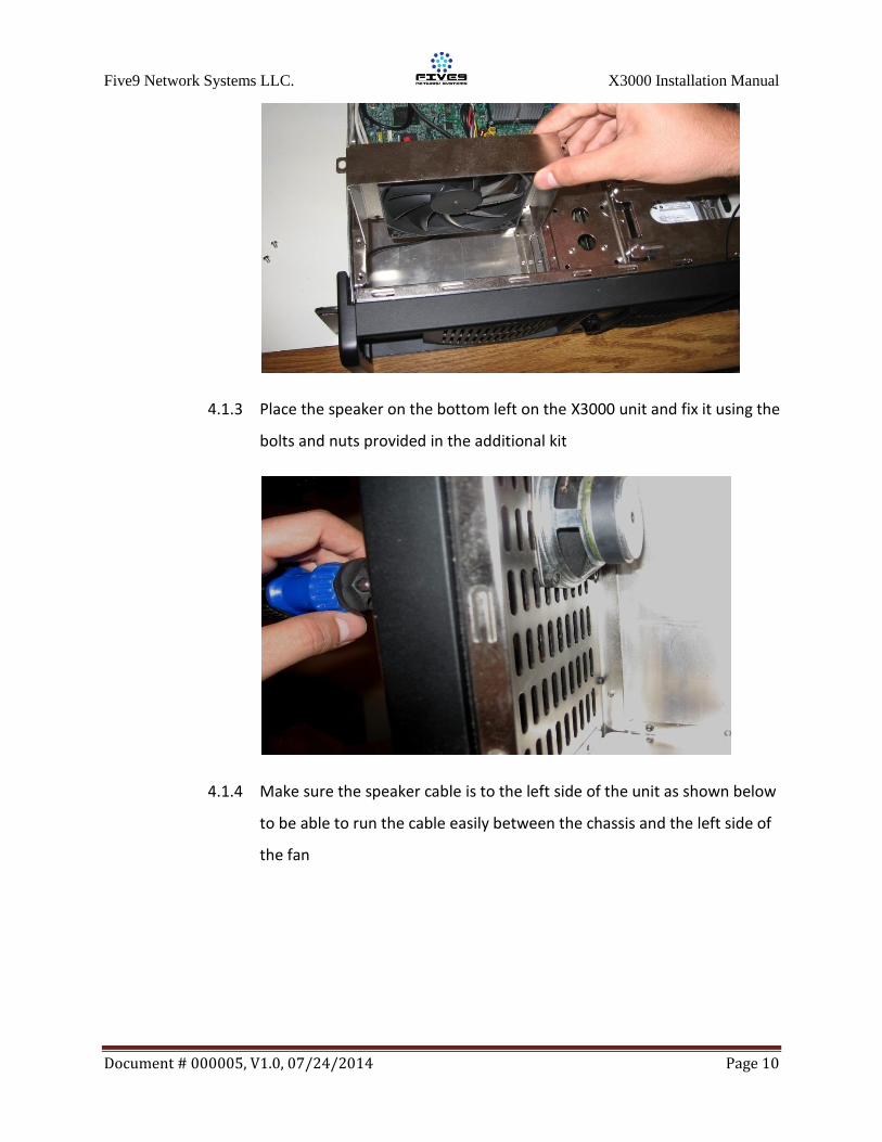
4.1.3 Place the speaker on the bottom left on the X3000 unit and fix it using the
bolts and nuts provided in the additional kit
4.1.4 Make sure the speaker cable is to the left side of the unit as shown below
to be able to run the cable easily between the chassis and the left side of
the fan
Five9 Network Systems LLC. X3000 Installation Manual
Document # 000005, V1.0, 07/24/2014 Page 11
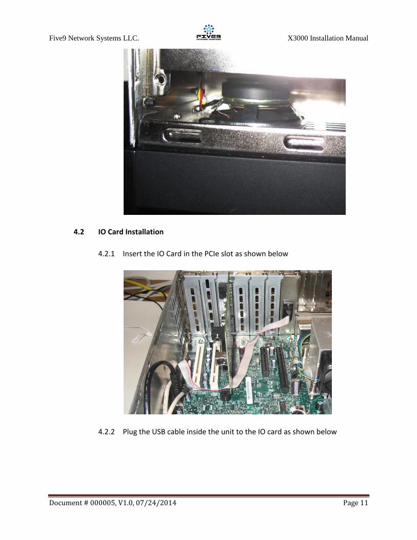
4.2 IO Card Installation
4.2.1 Insert the IO Card in the PCIe slot as shown below
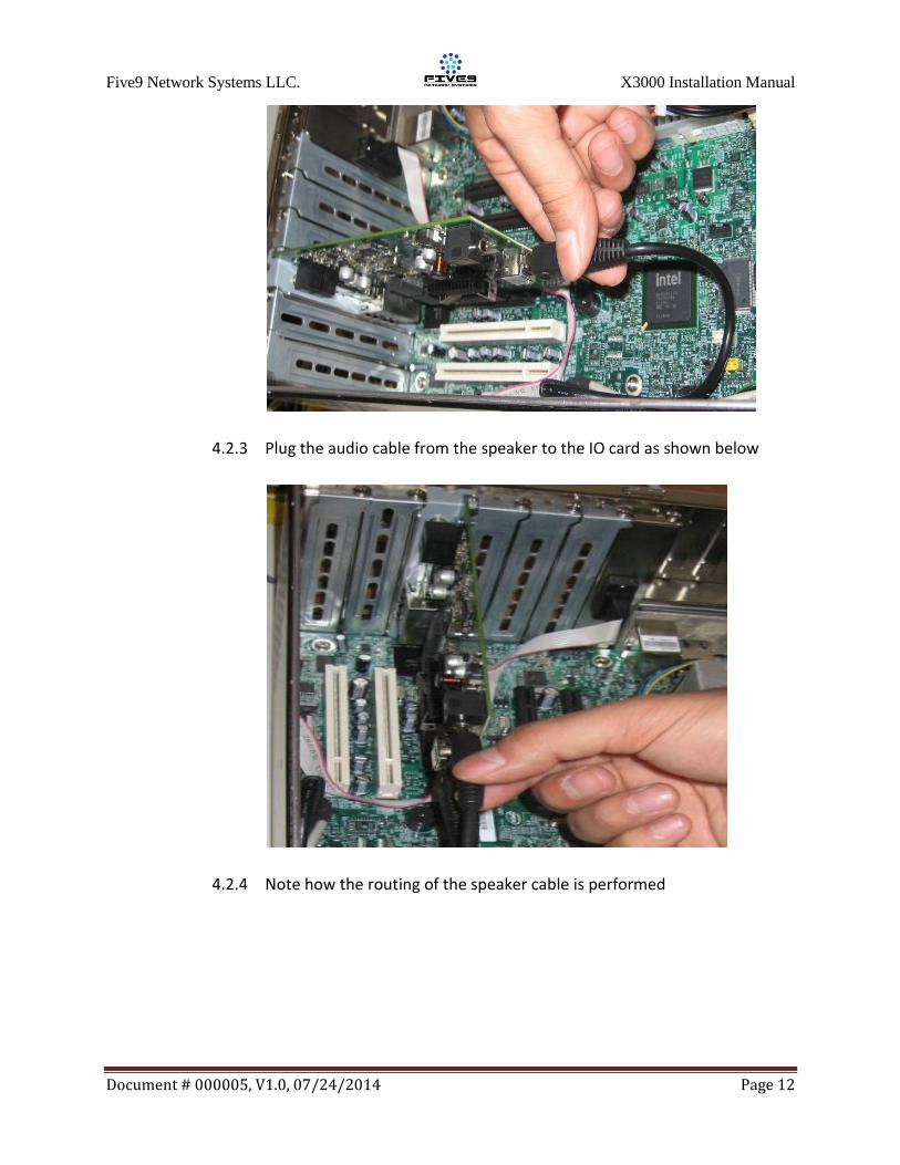
4.2.2 Plug the USB cable inside the unit to the IO card as shown below
Five9 Network Systems LLC. X3000 Installation Manual
Document # 000005, V1.0, 07/24/2014 Page 12
4.2.3 Plug the audio cable from the speaker to the IO card as shown below
4.2.4 Note how the routing of the speaker cable is performed
Five9 Network Systems LLC. X3000 Installation Manual
Document # 000005, V1.0, 07/24/2014 Page 13
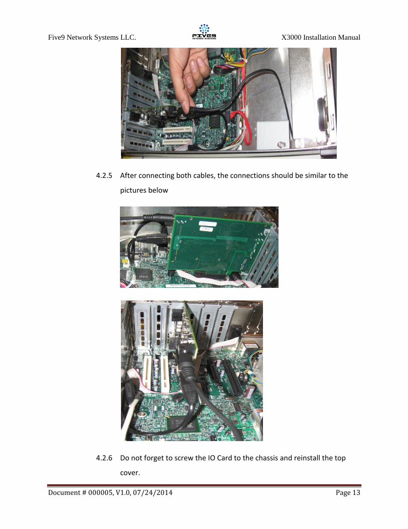
4.2.5 After connecting both cables, the connections should be similar to the
pictures below
4.2.6 Do not forget to screw the IO Card to the chassis and reinstall the top
cover.