Embed Size (px)
Citation preview
Fixed Bearing Surgical TechniqueFixed Bearing Surgical Technique


Consulting Surgeons
Douglas Dennis, M.D.
Professor, Colorado School of Mines
Clinical Director, Rose Musculoskeletal Research Laboratory
Co-Director, Rose Institute for Joint Replacement
Denver, Colorado
Thomas S. Thornhill, M.D.
Chairman, Department of Orthopaedic Surgery,
Harvard Medical School
Orthopaedic Surgeon, Brigham and Women’s Hospital
Boston Massachusetts
Richard D. Scott, M.D.
Associate Clinical Professor, Harvard Medical School
Orthopaedic Surgeon, Brigham and Women’s Hospital, New
England Baptist Hospital
Boston Massachusetts

Contents
Introduction 1
Surgical Technique 2
Initial Preparation of the Tibia 8
Preparation of the Femur 14
Distal Resection 19
Anterior/Posterior Resection 21
Notch and Chamfer Resection 25
Final Preparation of the Tibia 32
Preparation of the Patella 36
Assembling the Prosthesis 38
Appendix I: The Cemented Tibial 46
and Femoral Stem Extensions
Appendix II: The IM Device for Tibial 49
Augmentation Resection
Appendix III: The External Tibial 51
Alignment System
Appendix IV: Femoral Revision 55
and Tibial Insert Compatibility
1
SIGMA® Revision Knee Surgery
Introduction
In total knee arthroplasty, failure may result from many
causes, including wear, aseptic loosening, infection, osteolysis,
ligamentous instability, arthrofibrosis and patellofemoral
complications. In approaching revision procedures, the
surgeon must address such considerations as the planning of
an incision in a previously operated site, the condition of the
soft tissue, mobilisation of the extensor mechanism, extraction
of the primary prosthesis and the attendant conservation
of bone stock. Amongst the goals of successful revision
arthroplasty are the restoration of anatomical alignment
and functional stability, fixation of the revision implants and
accurate re-establishment of the joint line. Careful selection
of the appropriate prosthesis is of paramount importance.
Ideally, the revision knee replacement system will offer
the options of adjunctive stem fixation and variable stem
positions, femoral and tibial augmentation and various levels
of prosthetic constraint.
2
Surgical Technique
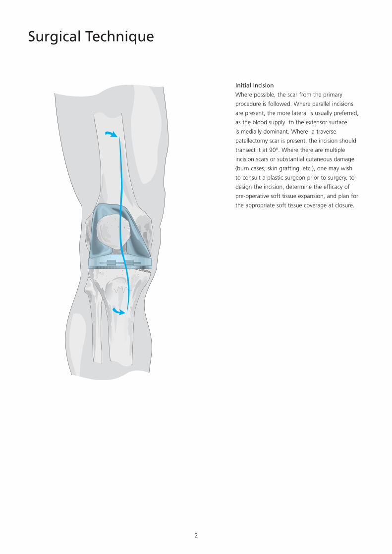
Initial Incision
Where possible, the scar from the primary
procedure is followed. Where parallel incisions
are present, the more lateral is usually preferred,
as the blood supply to the extensor surface
is medially dominant. Where a traverse
patellectomy scar is present, the incision should
transect it at 90°. Where there are multiple
incision scars or substantial cutaneous damage
(burn cases, skin grafting, etc.), one may wish
to consult a plastic surgeon prior to surgery, to
design the incision, determine the efficacy of
pre-operative soft tissue expansion, and plan for
the appropriate soft tissue coverage at closure.
3
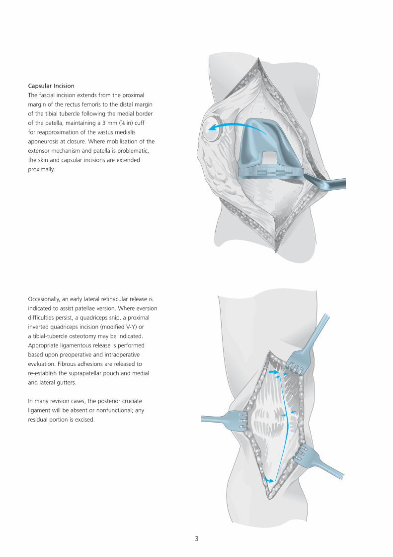
Occasionally, an early lateral retinacular release is
indicated to assist patellae version. Where eversion
difficulties persist, a quadriceps snip, a proximal
inverted quadriceps incision (modified V-Y) or
a tibial-tubercle osteotomy may be indicated.
Appropriate ligamentous release is performed
based upon preoperative and intraoperative
evaluation. Fibrous adhesions are released to
re-establish the suprapatellar pouch and medial
and lateral gutters.
In many revision cases, the posterior cruciate
ligament will be absent or nonfunctional; any
residual portion is excised.
Capsular Incision
The fascial incision extends from the proximal
margin of the rectus femoris to the distal margin
of the tibial tubercle following the medial border
of the patella, maintaining a 3 mm (1⁄8 in) cuff
for reapproximation of the vastus medialis
aponeurosis at closure. Where mobilisation of the
extensor mechanism and patella is problematic,
the skin and capsular incisions are extended
proximally.

4
SIGMA is Comprised of the Following
Components:
• Stabilised Femoral Component available in
seven sizes
• TC3 Femoral Component available in six sizes
• Ability to up/downsize femur to tibia
• 4 mm, 8 mm, 12 mm and 16 mm Distal
Femoral Augmentations
• Three anteroposterior Femoral Stem Positions:
0, +2 and -2 mm
• 125 mm and 175 mm Fluted Femoral Stem
Lengths in 10 mm to 24 mm diameters in 2
mm increments at 5° and 7° valgus angles
• 90 mm and 130 mm Cemented Femoral Stem
Lengths in 13 mm and 15 mm diameters at 5°
and 7° valgus angles
• Three levels of tibial insert constraint: Posterior
Stabilised, Stabilised Plus and TC3
• Three types of Tibial Wedge Augmentation
Components: Hemi Wedge in 10° and 20°
angles; Step Wedge in 10 mm and 15 mm
thickness; and Full Wedge in 10° and 15°
angles.
• 75 mm, 115 mm and 150 mm Fluted Tibial
Stem Lengths in 10 mm and to 24 mm
diameters in 2 mm increments
• 30 mm and 60 mm Cemented Tibial Stem
Lengths in 13 mm and 15 mm diameters
• Systematic and simple instrumentation system
to accommodate each of the component
options and surgical preferences based upon
a patented Rod and Sleeve Intramedullary
alignment system.
5
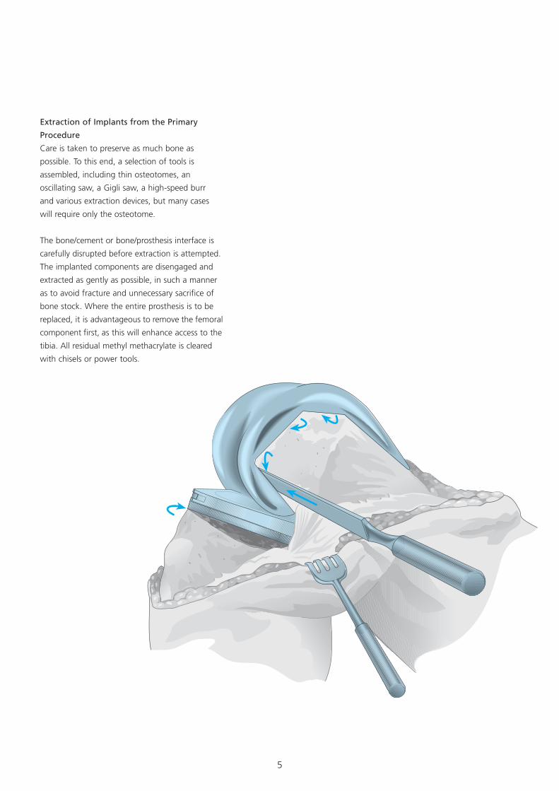
Extraction of Implants from the Primary
Procedure
Care is taken to preserve as much bone as
possible. To this end, a selection of tools is
assembled, including thin osteotomes, an
oscillating saw, a Gigli saw, a high-speed burr
and various extraction devices, but many cases
will require only the osteotome.
The bone/cement or bone/prosthesis interface is
carefully disrupted before extraction is attempted.
The implanted components are disengaged and
extracted as gently as possible, in such a manner
as to avoid fracture and unnecessary sacrifice of
bone stock. Where the entire prosthesis is to be
replaced, it is advantageous to remove the femoral
component first, as this will enhance access to the
tibia. All residual methyl methacrylate is cleared
with chisels or power tools.
6
Interpretive Evaluation
Recommended Surgical Priority
1) Tibial medullary canal preparation
2) Proximal tibial resection
3) Femoral medullary canal preparation
4) Distal femoral resection
5) Establishment of femoral rotation
6) Anteroposterior, notch and chamfer resection
7) Establishment of femoral rotation
8) Tibial deficit augmentation
9) Final tibial preparation
10) Patellar preparation
11) Implantation of components
The surgeon should establish two anatomic
conditions to facilitate revision arthroplasty:
the level of the joint line and the disparity in
the flexion and extension gaps.
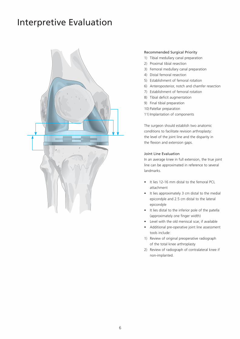
Joint Line Evaluation
In an average knee in full extension, the true joint
line can be approximated in reference to several
landmarks.
• It lies 12-16 mm distal to the femoral PCL
attachment
• It lies approximately 3 cm distal to the medial
epicondyle and 2.5 cm distal to the lateral
epicondyle
• It lies distal to the inferior pole of the patella
(approximately one finger width)
• Level with the old meniscal scar, if available
• Additional pre-operative joint line assessment
tools include:
1) Review of original preoperative radiograph
of the total knee arthroplasty
2) Review of radiograph of contralateral knee if
non-implanted.
7
Where significant flexion laxity persists, despite
these manoeuvres, consider the use of the TC3
component.
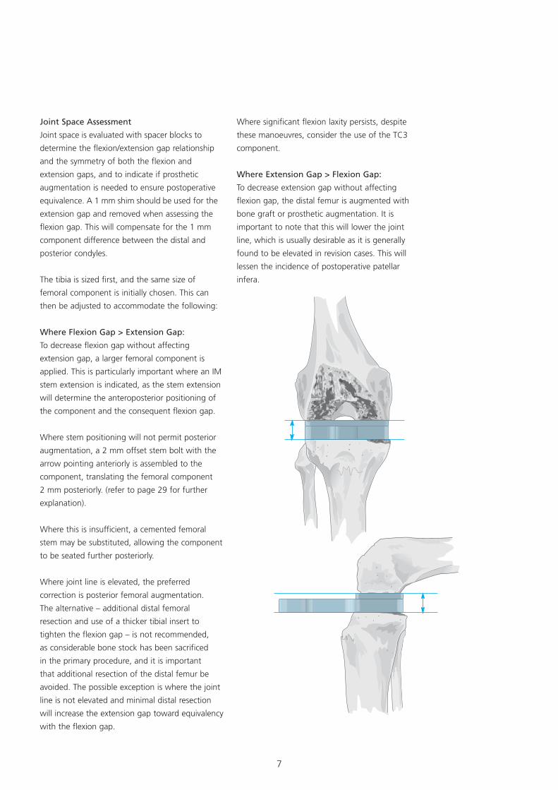
Where Extension Gap > Flexion Gap:
To decrease extension gap without affecting
flexion gap, the distal femur is augmented with
bone graft or prosthetic augmentation. It is
important to note that this will lower the joint
line, which is usually desirable as it is generally
found to be elevated in revision cases. This will
lessen the incidence of postoperative patellar
infera.
Joint Space Assessment
Joint space is evaluated with spacer blocks to
determine the flexion/extension gap relationship
and the symmetry of both the flexion and
extension gaps, and to indicate if prosthetic
augmentation is needed to ensure postoperative
equivalence. A 1 mm shim should be used for the
extension gap and removed when assessing the
flexion gap. This will compensate for the 1 mm
component difference between the distal and
posterior condyles.
The tibia is sized first, and the same size of
femoral component is initially chosen. This can
then be adjusted to accommodate the following:
Where Flexion Gap > Extension Gap:
To decrease flexion gap without affecting
extension gap, a larger femoral component is
applied. This is particularly important where an IM
stem extension is indicated, as the stem extension
will determine the anteroposterior positioning of
the component and the consequent flexion gap.
Where stem positioning will not permit posterior
augmentation, a 2 mm offset stem bolt with the
arrow pointing anteriorly is assembled to the
component, translating the femoral component
2 mm posteriorly. (refer to page 29 for further
explanation).
Where this is insufficient, a cemented femoral
stem may be substituted, allowing the component
to be seated further posteriorly.
Where joint line is elevated, the preferred
correction is posterior femoral augmentation.
The alternative – additional distal femoral
resection and use of a thicker tibial insert to
tighten the flexion gap – is not recommended,
as considerable bone stock has been sacrificed
in the primary procedure, and it is important
that additional resection of the distal femur be
avoided. The possible exception is where the joint
line is not elevated and minimal distal resection
will increase the extension gap toward equivalency
with the flexion gap.
8
Initial Preparation of the Tibia
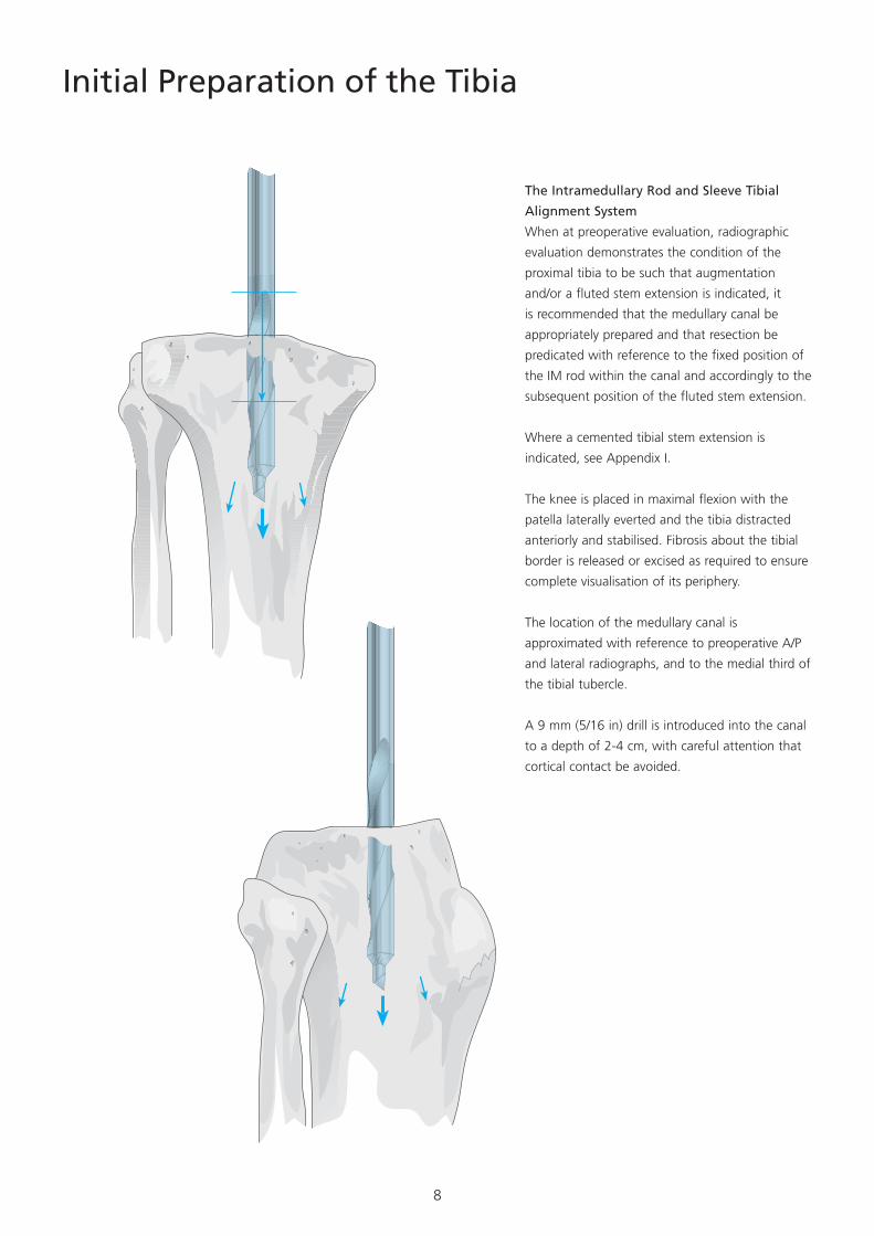
The Intramedullary Rod and Sleeve Tibial
Alignment System
When at preoperative evaluation, radiographic
evaluation demonstrates the condition of the
proximal tibia to be such that augmentation
and/or a fluted stem extension is indicated, it
is recommended that the medullary canal be
appropriately prepared and that resection be
predicated with reference to the fixed position of
the IM rod within the canal and accordingly to the
subsequent position of the fluted stem extension.
Where a cemented tibial stem extension is
indicated, see Appendix I.
The knee is placed in maximal flexion with the
patella laterally everted and the tibia distracted
anteriorly and stabilised. Fibrosis about the tibial
border is released or excised as required to ensure
complete visualisation of its periphery.
The location of the medullary canal is
approximated with reference to preoperative A/P
and lateral radiographs, and to the medial third of
the tibial tubercle.
A 9 mm (5/16 in) drill is introduced into the canal
to a depth of 2-4 cm, with careful attention that
cortical contact be avoided.
9
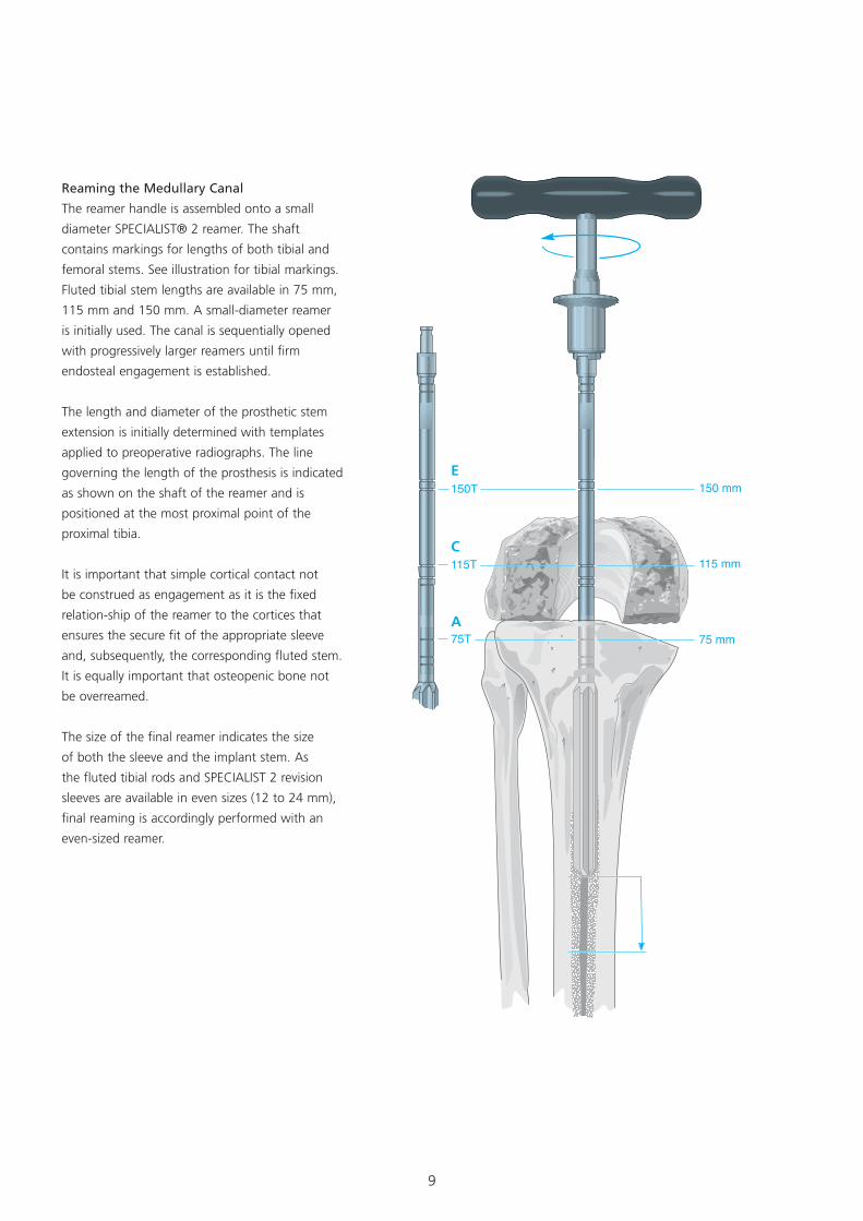
Reaming the Medullary Canal
The reamer handle is assembled onto a small
diameter SPECIALIST® 2 reamer. The shaft
contains markings for lengths of both tibial and
femoral stems. See illustration for tibial markings.
Fluted tibial stem lengths are available in 75 mm,
115 mm and 150 mm. A small-diameter reamer
is initially used. The canal is sequentially opened
with progressively larger reamers until firm
endosteal engagement is established.
The length and diameter of the prosthetic stem
extension is initially determined with templates
applied to preoperative radiographs. The line
governing the length of the prosthesis is indicated
as shown on the shaft of the reamer and is
positioned at the most proximal point of the
proximal tibia.
It is important that simple cortical contact not
be construed as engagement as it is the fixed
relation-ship of the reamer to the cortices that
ensures the secure fit of the appropriate sleeve
and, subsequently, the corresponding fluted stem.
It is equally important that osteopenic bone not
be overreamed.
The size of the final reamer indicates the size
of both the sleeve and the implant stem. As
the fluted tibial rods and SPECIALIST 2 revision
sleeves are available in even sizes (12 to 24 mm),
final reaming is accordingly performed with an
even-sized reamer.
E
C
A

10
Positioning the Rod and Sleeve
The intramedullary rods are provided in three
lengths to accommodate various sizes of tibia.
The appropriate rod is selected, inserted through
the sleeve corresponding to the size of the
final reamer and advanced to the distal end.
The handle is subsequently assembled to the
rod. The sleeve is rotated 180° clockwise on
the rod and retracted toward the handle until
locked in position. The rod and sleeve assembly
are subsequently introduced into the prepared
medullary canal and carefully advanced. The
sleeve will fit snugly within the reamed canal,
but excessive force is not required. Advancement
proceeds until the predetemined depth as
indicated on the rod is aligned with the proximal
surface of the tibia established by the primary
procedure. As the depth markings on the IM rod
correspond to those of the T-handled reamer,
insertion of the sleeve will not exceed the depth
reamed.
For Tibial Fluted Stem Lengths
A 75 mm
C 115 mm
D 150 mm
11
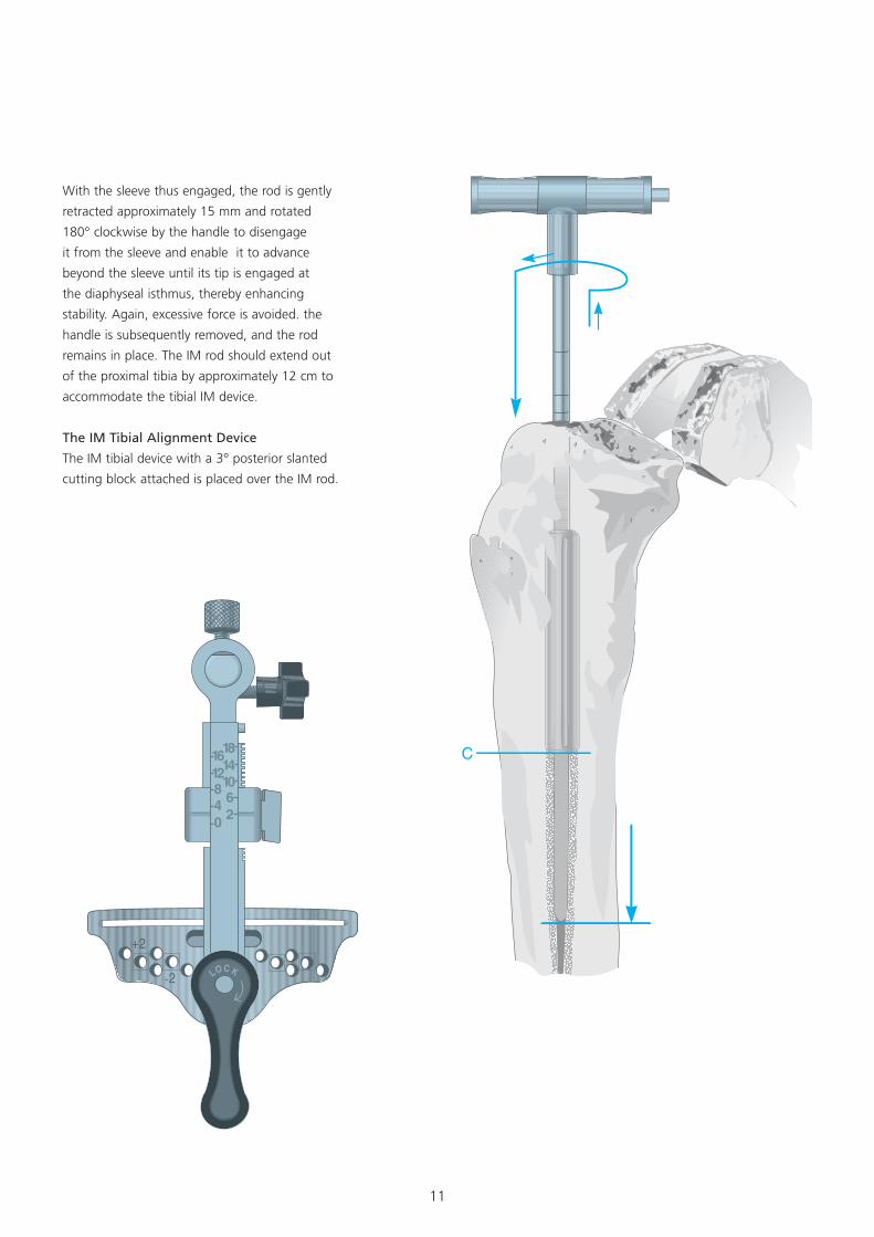
With the sleeve thus engaged, the rod is gently
retracted approximately 15 mm and rotated
180° clockwise by the handle to disengage
it from the sleeve and enable it to advance
beyond the sleeve until its tip is engaged at
the diaphyseal isthmus, thereby enhancing
stability. Again, excessive force is avoided. the
handle is subsequently removed, and the rod
remains in place. The IM rod should extend out
of the proximal tibia by approximately 12 cm to
accommodate the tibial IM device.
The IM Tibial Alignment Device
The IM tibial device with a 3° posterior slanted
cutting block attached is placed over the IM rod.
12
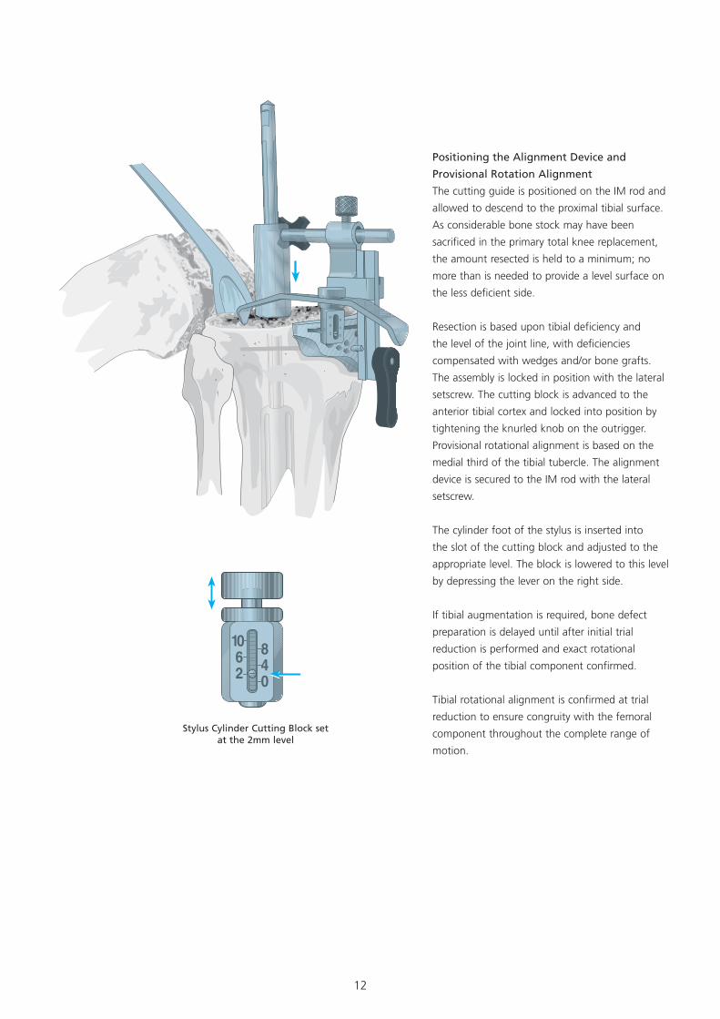
Positioning the Alignment Device and
Provisional Rotation Alignment
The cutting guide is positioned on the IM rod and
allowed to descend to the proximal tibial surface.
As considerable bone stock may have been
sacrificed in the primary total knee replacement,
the amount resected is held to a minimum; no
more than is needed to provide a level surface on
the less deficient side.
Resection is based upon tibial deficiency and
the level of the joint line, with deficiencies
compensated with wedges and/or bone grafts.
The assembly is locked in position with the lateral
setscrew. The cutting block is advanced to the
anterior tibial cortex and locked into position by
tightening the knurled knob on the outrigger.
Provisional rotational alignment is based on the
medial third of the tibial tubercle. The alignment
device is secured to the IM rod with the lateral
setscrew.
The cylinder foot of the stylus is inserted into
the slot of the cutting block and adjusted to the
appropriate level. The block is lowered to this level
by depressing the lever on the right side.
If tibial augmentation is required, bone defect
preparation is delayed until after initial trial
reduction is performed and exact rotational
position of the tibial component confirmed.
Tibial rotational alignment is confirmed at trial
reduction to ensure congruity with the femoral
component throughout the complete range of
motion.
Stylus Cylinder Cutting Block set at the 2mm level
13
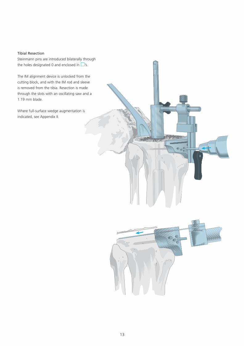
Tibial Resection
Steinmann pins are introduced bilaterally through
the holes designated 0 and enclosed in ’s.
The IM alignment device is unlocked from the
cutting block, and with the IM rod and sleeve
is removed from the tibia. Resection is made
through the slots with an oscillating saw and a
1.19 mm blade.
Where full-surface wedge augmentation is
indicated, see Appendix II.
14
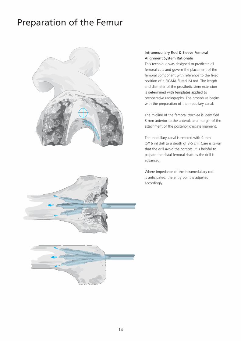
Preparation of the Femur
Intramedullary Rod & Sleeve Femoral
Alignment System Rationale
This technique was designed to predicate all
femoral cuts and govern the placement of the
femoral component with reference to the fixed
position of a SIGMA fluted IM rod. The length
and diameter of the prosthetic stem extension
is determined with templates applied to
preoperative radiographs. The procedure begins
with the preparation of the medullary canal.
The midline of the femoral trochlea is identified
3 mm anterior to the anterolateral margin of the
attachment of the posterior cruciate ligament.
The medullary canal is entered with 9 mm
(5/16 in) drill to a depth of 3-5 cm. Care is taken
that the drill avoid the cortices. It is helpful to
palpate the distal femoral shaft as the drill is
advanced.
Where impedance of the intramedullary rod
is anticipated, the entry point is adjusted
accordingly.
15
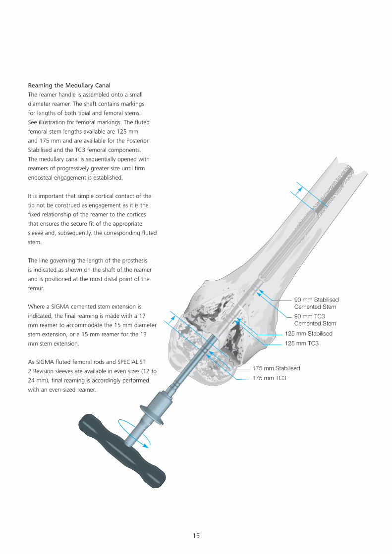
90 mm StabilisedCemented Stem90 mm TC3Cemented Stem
125 mm Stabilised125 mm TC3
175 mm Stabilised175 mm TC3
Reaming the Medullary Canal
The reamer handle is assembled onto a small
diameter reamer. The shaft contains markings
for lengths of both tibial and femoral stems.
See illustration for femoral markings. The fluted
femoral stem lengths available are 125 mm
and 175 mm and are available for the Posterior
Stabilised and the TC3 femoral components.
The medullary canal is sequentially opened with
reamers of progressively greater size until firm
endosteal engagement is established.
It is important that simple cortical contact of the
tip not be construed as engagement as it is the
fixed relationship of the reamer to the cortices
that ensures the secure fit of the appropriate
sleeve and, subsequently, the corresponding fluted
stem.
The line governing the length of the prosthesis
is indicated as shown on the shaft of the reamer
and is positioned at the most distal point of the
femur.
Where a SIGMA cemented stem extension is
indicated, the final reaming is made with a 17
mm reamer to accommodate the 15 mm diameter
stem extension, or a 15 mm reamer for the 13
mm stem extension.
As SIGMA fluted femoral rods and SPECIALIST
2 Revision sleeves are available in even sizes (12 to
24 mm), final reaming is accordingly performed
with an even-sized reamer.
16
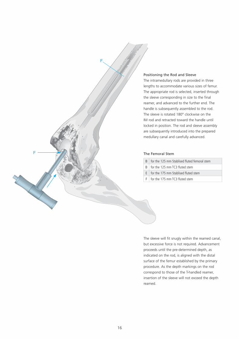
The sleeve will fit snugly within the reamed canal,
but excessive force is not required. Advancement
proceeds until the pre-determined depth, as
indicated on the rod, is aligned with the distal
surface of the femur established by the primary
procedure. As the depth markings on the rod
correspond to those of the T-handled reamer,
insertion of the sleeve will not exceed the depth
reamed.
Positioning the Rod and Sleeve
The intramedullary rods are provided in three
lengths to accommodate various sizes of femur.
The appropriate rod is selected, inserted through
the sleeve corresponding in size to the final
reamer, and advanced to the further end. The
handle is subsequently assembled to the rod.
The sleeve is rotated 180° clockwise on the
IM rod and retracted toward the handle until
locked in position. The rod and sleeve assembly
are subsequently introduced into the prepared
medullary canal and carefully advanced.
The Femoral Stem
B for the 125 mm Stablised fluted femoral stem
B for the 125 mm TC3 fluted stem
E for the 175 mm Stablised fluted stem
F for the 175 mm TC3 fluted stem
17
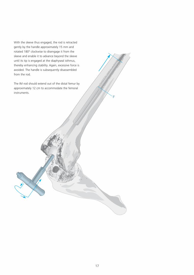
With the sleeve thus engaged, the rod is retracted
gently by the handle approximately 15 mm and
rotated 180° clockwise to disengage it from the
sleeve and enable it to advance beyond the sleeve
until its tip is engaged at the diaphyseal isthmus,
thereby enhancing stability. Again, excessive force is
avoided. The handle is subsequently disassembled
from the rod.
The IM rod should extend out of the distal femur by
approximately 12 cm to accommodate the femoral
instruments.
18
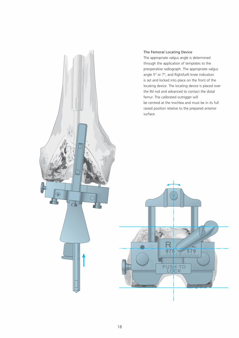
The Femoral Locating Device
The appropriate valgus angle is determined
through the application of templates to the
preoperative radiograph. The appropriate valgus
angle 5° or 7°, and Right/Left knee indication
is set and locked into place on the front of the
locating device. The locating device is placed over
the IM rod and advanced to contact the distal
femur. The calibrated outrigger will
be centred at the trochlea and must be in its full
raised position relative to the prepared anterior
surface.
19
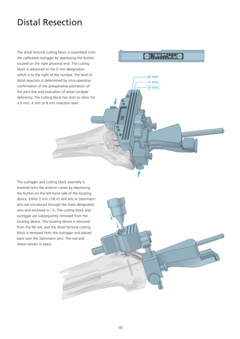
Distal Resection
The distal femoral cutting block is assembled onto
the calibrated outrigger by depressing the button
located on the right proximal end. The cutting
block is advanced to the 0 mm designation
which is to the right of the number. The level of
distal resection is determined by intra-operative
confirmation of the preoperative estimation of
the joint line and evaluation of distal condylar
deficiency. The cutting block has slots to allow for
a 0 mm, 4 mm or 8 mm resection level.
The outrigger and cutting block assembly is
lowered onto the anterior cortex by depressing
the button on the left-hand side of the locating
device. Either 3 mm (1/8 in) drill bits or Steinmann
pins are introduced through the holes designated
zero and enclosed in ’s. The cutting block and
outrigger are subsequently removed from the
locating device. The locating device is removed
from the IM rod, and the distal femoral cutting
block is removed from the outrigger and placed
back over the Steinmann pins. The rod and
sleeve remain in place.
20
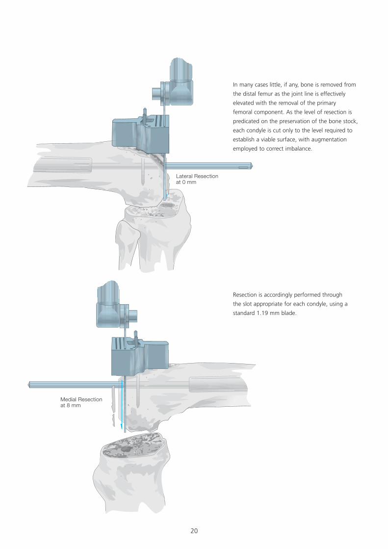
Lateral Resectionat 0 mm
Medial Resectionat 8 mm
In many cases little, if any, bone is removed from
the distal femur as the joint line is effectively
elevated with the removal of the primary
femoral component. As the level of resection is
predicated on the preservation of the bone stock,
each condyle is cut only to the level required to
establish a viable surface, with augmentation
employed to correct imbalance.
Resection is accordingly performed through
the slot appropriate for each condyle, using a
standard 1.19 mm blade.
21
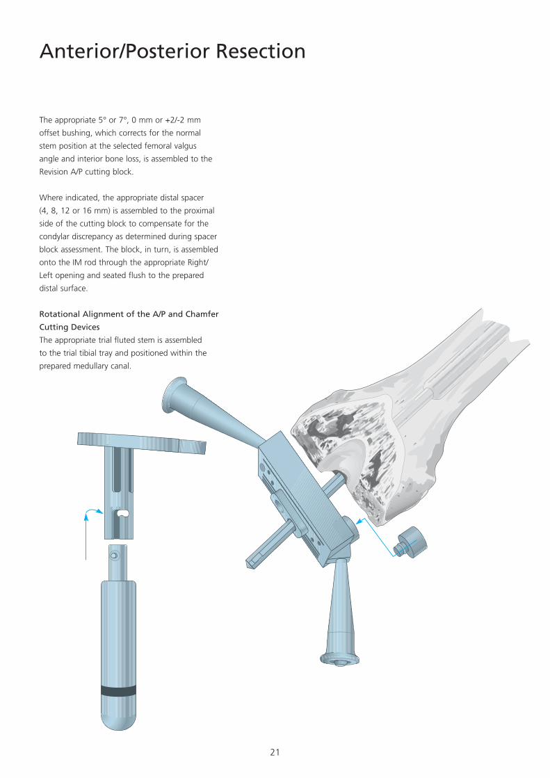
Anterior/Posterior Resection
The appropriate 5° or 7°, 0 mm or +2/-2 mm
offset bushing, which corrects for the normal
stem position at the selected femoral valgus
angle and interior bone loss, is assembled to the
Revision A/P cutting block.
Where indicated, the appropriate distal spacer
(4, 8, 12 or 16 mm) is assembled to the proximal
side of the cutting block to compensate for the
condylar discrepancy as determined during spacer
block assessment. The block, in turn, is assembled
onto the IM rod through the appropriate Right/
Left opening and seated flush to the prepared
distal surface.
Rotational Alignment of the A/P and Chamfer
Cutting Devices
The appropriate trial fluted stem is assembled
to the trial tibial tray and positioned within the
prepared medullary canal.
22
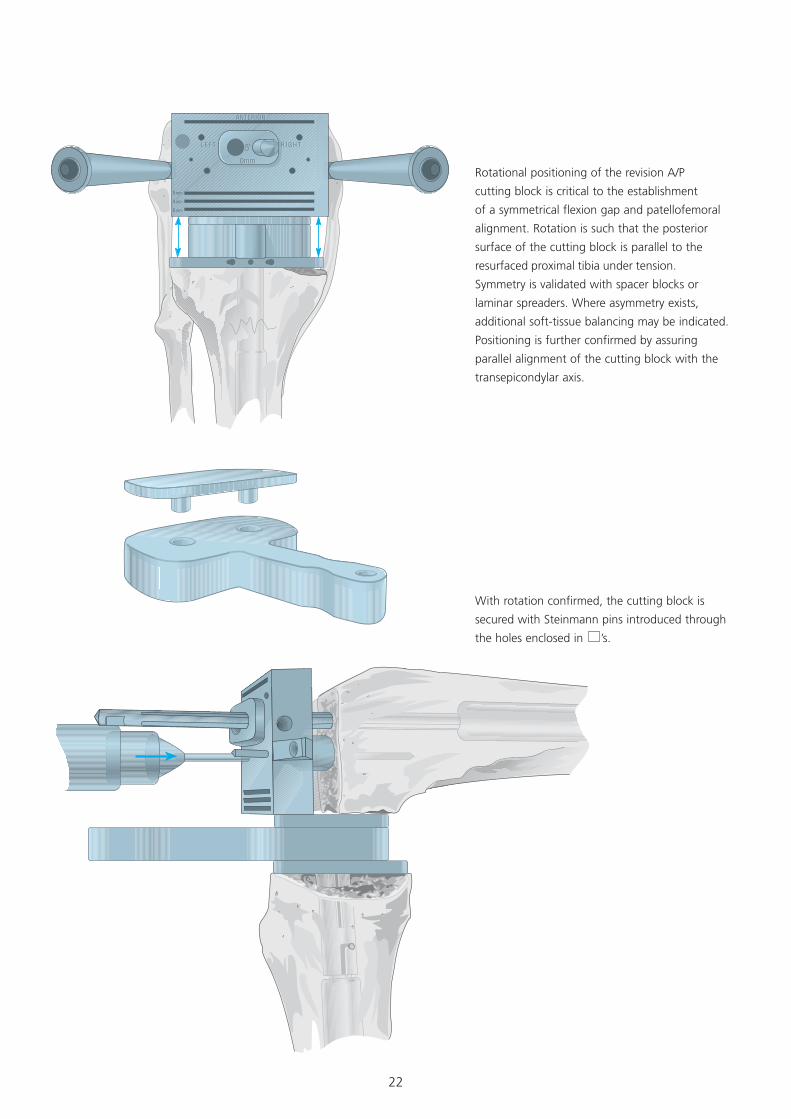
Rotational positioning of the revision A/P
cutting block is critical to the establishment
of a symmetrical flexion gap and patellofemoral
alignment. Rotation is such that the posterior
surface of the cutting block is parallel to the
resurfaced proximal tibia under tension.
Symmetry is validated with spacer blocks or
laminar spreaders. Where asymmetry exists,
additional soft-tissue balancing may be indicated.
Positioning is further confirmed by assuring
parallel alignment of the cutting block with the
transepicondylar axis.
With rotation confirmed, the cutting block is
secured with Steinmann pins introduced through
the holes enclosed in ’s.
23
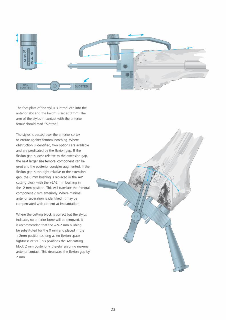
The foot plate of the stylus is introduced into the
anterior slot and the height is set at 0 mm. The
arm of the stylus in contact with the anterior
femur should read “Slotted”.
The stylus is passed over the anterior cortex
to ensure against femoral notching. Where
obstruction is identified, two options are available
and are predicated by the flexion gap. If the
flexion gap is loose relative to the extension gap,
the next larger size femoral component can be
used and the posterior condyles augmented. If the
flexion gap is too tight relative to the extension
gap, the 0 mm bushing is replaced in the A/P
cutting block with the +2/-2 mm bushing in
the -2 mm position. This will translate the femoral
component 2 mm anteriorly. Where minimal
anterior separation is identified, it may be
compensated with cement at implantation.
Where the cutting block is correct but the stylus
indicates no anterior bone will be removed, it
is recommended that the +2/-2 mm bushing
be substituted for the 0 mm and placed in the
+ 2mm position as long as no flexion space
tightness exists. This positions the A/P cutting
block 2 mm posteriorly, thereby ensuring maximal
anterior contact. This decreases the flexion gap by
2 mm.
24
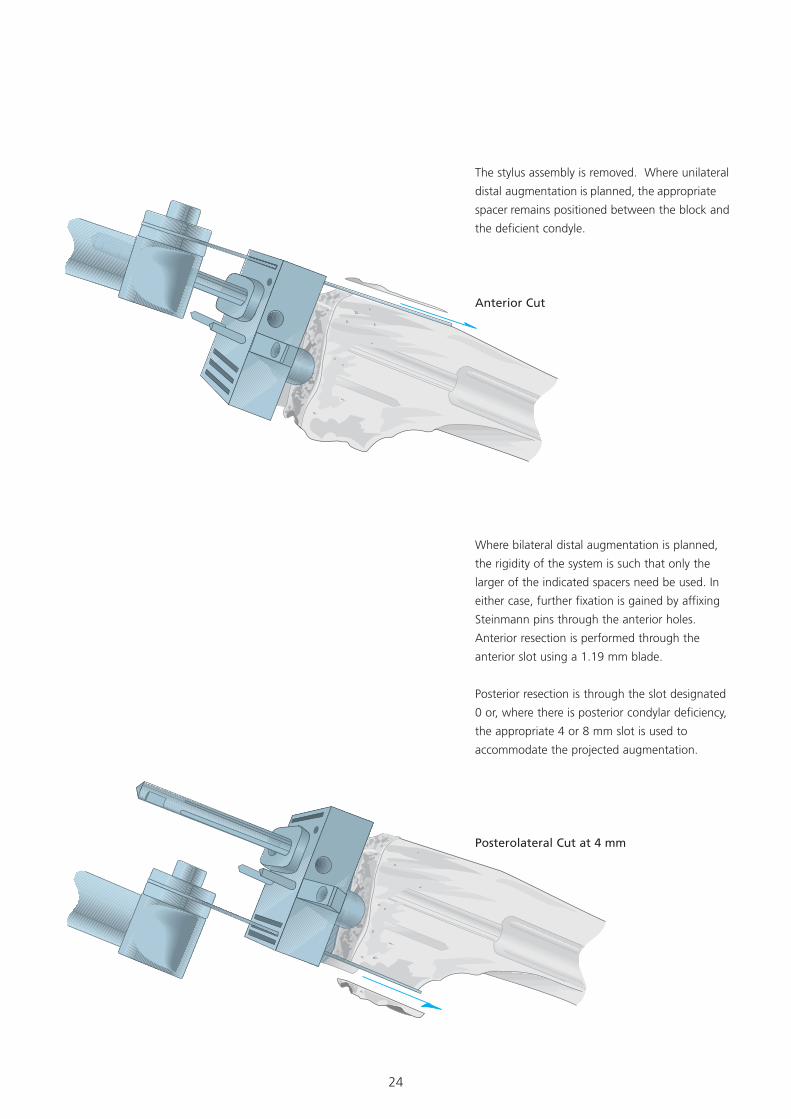
Where bilateral distal augmentation is planned,
the rigidity of the system is such that only the
larger of the indicated spacers need be used. In
either case, further fixation is gained by affixing
Steinmann pins through the anterior holes.
Anterior resection is performed through the
anterior slot using a 1.19 mm blade.
Posterior resection is through the slot designated
0 or, where there is posterior condylar deficiency,
the appropriate 4 or 8 mm slot is used to
accommodate the projected augmentation.
Anterior Cut
Posterolateral Cut at 4 mm
The stylus assembly is removed. Where unilateral
distal augmentation is planned, the appropriate
spacer remains positioned between the block and
the deficient condyle.
25
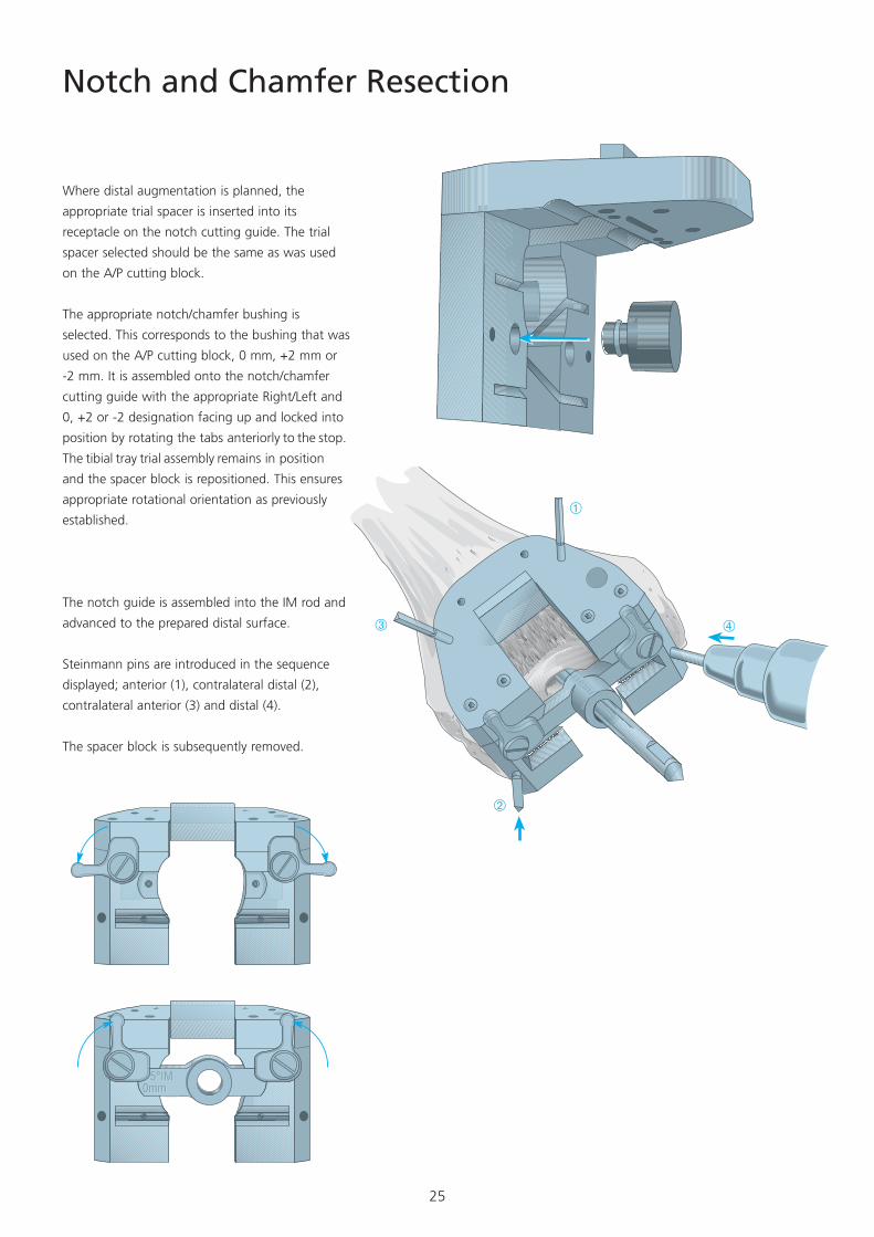
The notch guide is assembled into the IM rod and
advanced to the prepared distal surface.
Steinmann pins are introduced in the sequence
displayed; anterior (1), contralateral distal (2),
contralateral anterior (3) and distal (4).
The spacer block is subsequently removed.
Notch and Chamfer Resection
Where distal augmentation is planned, the
appropriate trial spacer is inserted into its
receptacle on the notch cutting guide. The trial
spacer selected should be the same as was used
on the A/P cutting block.
The appropriate notch/chamfer bushing is
selected. This corresponds to the bushing that was
used on the A/P cutting block, 0 mm, +2 mm or
-2 mm. It is assembled onto the notch/chamfer
cutting guide with the appropriate Right/Left and
0, +2 or -2 designation facing up and locked into
position by rotating the tabs anteriorly to the stop.
The tibial tray trial assembly remains in position
and the spacer block is repositioned. This ensures
appropriate rotational orientation as previously
established.
26
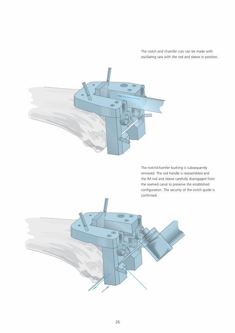
The notch and chamfer cuts can be made with
oscillating saw with the rod and sleeve in position.
The notch/chamfer bushing is subsequently
removed. The rod handle is reassembled and
the IM rod and sleeve carefully disengaged from
the reamed canal to preserve the established
configuration. The security of the notch guide is
confirmed.
27
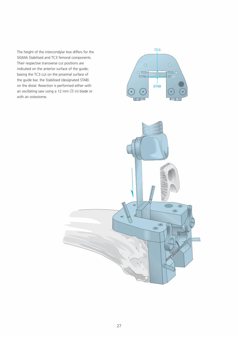
The height of the intercondylar box differs for the
SIGMA Stabilised and TC3 femoral components.
Their respective transverse cut positions are
indicated on the anterior surface of the guide;
basing the TC3 cut on the proximal surface of
the guide bar, the Stabilised (designated STAB)
on the distal. Resection is performed either with
an oscillating saw using a 12 mm (1⁄2 in) blade or
with an osteotome.
TC3STAB
TC3STAB
TC3
STAB
TC3STAB�TC3
STAB
28
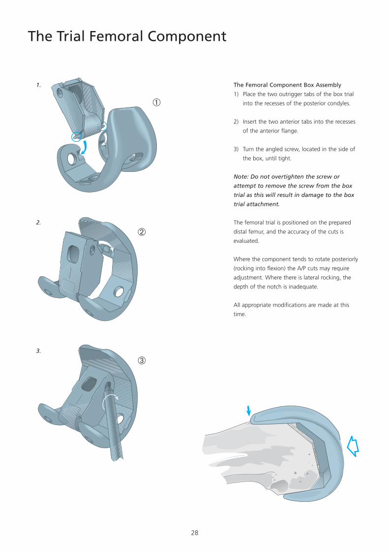
The Trial Femoral Component
The Femoral Component Box Assembly
1) Place the two outrigger tabs of the box trial
into the recesses of the posterior condyles.
2) Insert the two anterior tabs into the recesses
of the anterior flange.
3) Turn the angled screw, located in the side of
the box, until tight.
Note: Do not overtighten the screw or
attempt to remove the screw from the box
trial as this will result in damage to the box
trial attachment.
The femoral trial is positioned on the prepared
distal femur, and the accuracy of the cuts is
evaluated.
Where the component tends to rotate posteriorly
(rocking into flexion) the A/P cuts may require
adjustment. Where there is lateral rocking, the
depth of the notch is inadequate.
All appropriate modifications are made at this
time.
�
�
�
�
�
�
�
�
�
1.
2.
3.
29
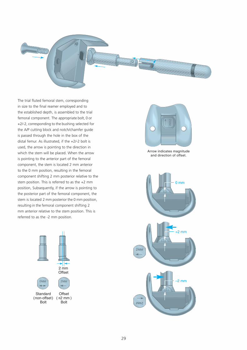
The trial fluted femoral stem, corresponding
in size to the final reamer employed and to
the established depth, is assembled to the trial
femoral component. The appropriate bolt, 0 or
+2/-2, corresponding to the bushing selected for
the A/P cutting block and notch/chamfer guide
is passed through the hole in the box of the
distal femur. As illustrated, if the +2/-2 bolt is
used, the arrow is pointing to the direction in
which the stem will be placed. When the arrow
is pointing to the anterior part of the femoral
component, the stem is located 2 mm anterior
to the 0 mm position, resulting in the femoral
component shifting 2 mm posterior relative to the
stem position. This is referred to as the +2 mm
position, Subsequently, if the arrow is pointing to
the posterior part of the femoral component, the
stem is located 2 mm posterior the 0 mm position,
resulting in the femoral component shifting 2
mm anterior relative to the stem position. This is
referred to as the -2 mm position.
30
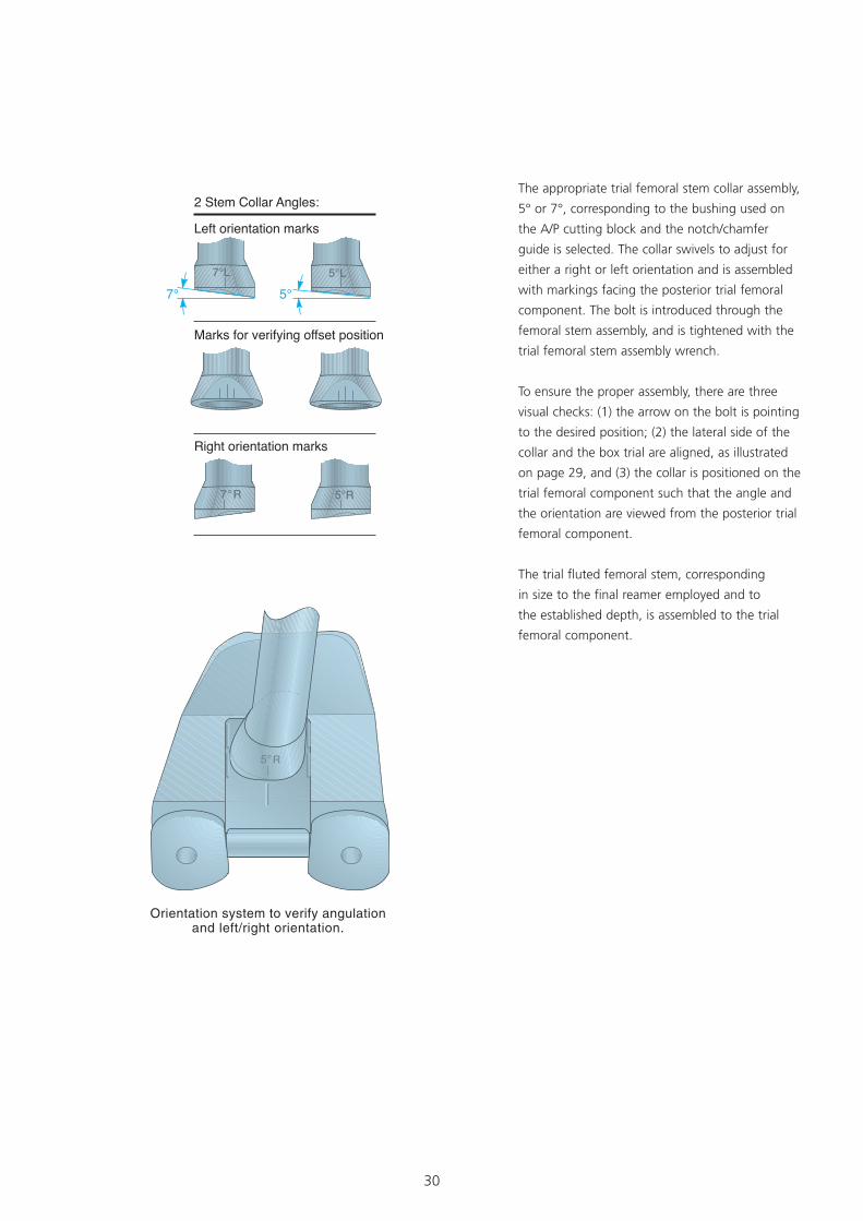
The appropriate trial femoral stem collar assembly,
5° or 7°, corresponding to the bushing used on
the A/P cutting block and the notch/chamfer
guide is selected. The collar swivels to adjust for
either a right or left orientation and is assembled
with markings facing the posterior trial femoral
component. The bolt is introduced through the
femoral stem assembly, and is tightened with the
trial femoral stem assembly wrench.
To ensure the proper assembly, there are three
visual checks: (1) the arrow on the bolt is pointing
to the desired position; (2) the lateral side of the
collar and the box trial are aligned, as illustrated
on page 29, and (3) the collar is positioned on the
trial femoral component such that the angle and
the orientation are viewed from the posterior trial
femoral component.
The trial fluted femoral stem, corresponding
in size to the final reamer employed and to
the established depth, is assembled to the trial
femoral component.
31
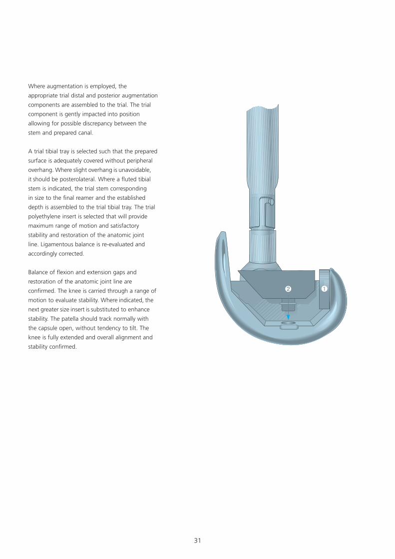
Where augmentation is employed, the
appropriate trial distal and posterior augmentation
components are assembled to the trial. The trial
component is gently impacted into position
allowing for possible discrepancy between the
stem and prepared canal.
A trial tibial tray is selected such that the prepared
surface is adequately covered without peripheral
overhang. Where slight overhang is unavoidable,
it should be posterolateral. Where a fluted tibial
stem is indicated, the trial stem corresponding
in size to the final reamer and the established
depth is assembled to the trial tibial tray. The trial
polyethylene insert is selected that will provide
maximum range of motion and satisfactory
stability and restoration of the anatomic joint
line. Ligamentous balance is re-evaluated and
accordingly corrected.
Balance of flexion and extension gaps and
restoration of the anatomic joint line are
confirmed. The knee is carried through a range of
motion to evaluate stability. Where indicated, the
next greater size insert is substituted to enhance
stability. The patella should track normally with
the capsule open, without tendency to tilt. The
knee is fully extended and overall alignment and
stability confirmed.
32
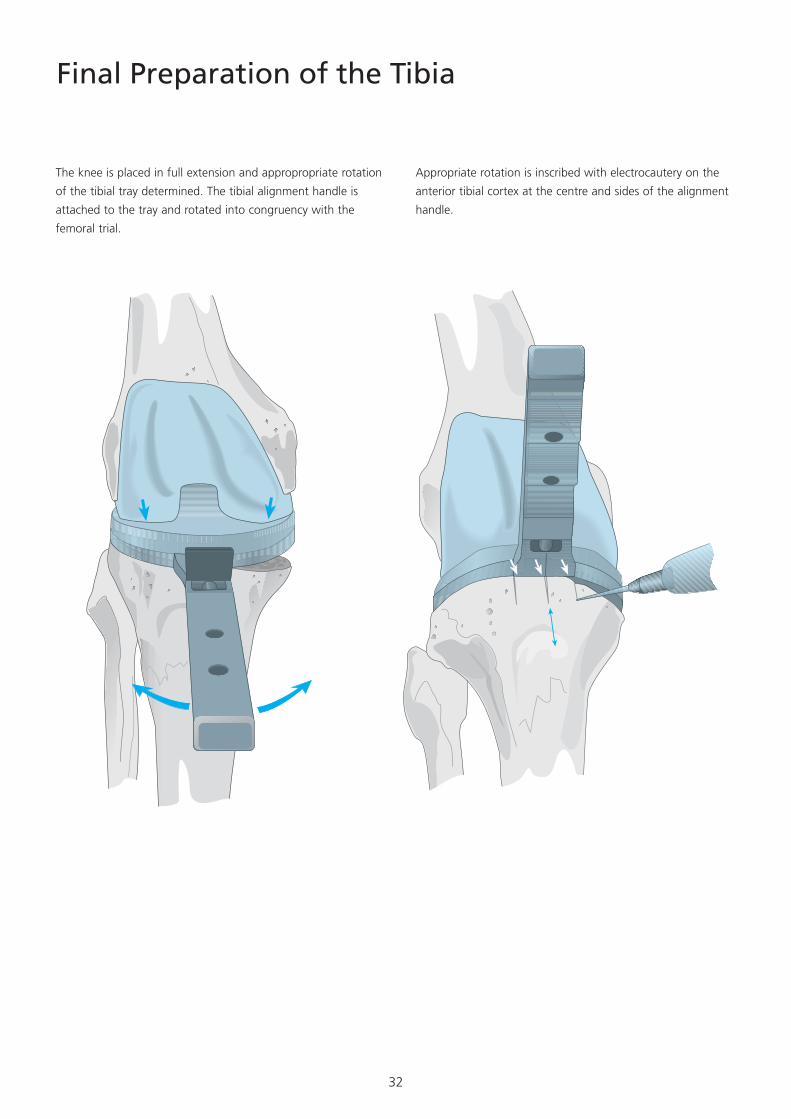
Final Preparation of the Tibia
The knee is placed in full extension and appropropriate rotation
of the tibial tray determined. The tibial alignment handle is
attached to the tray and rotated into congruency with the
femoral trial.
Appropriate rotation is inscribed with electrocautery on the
anterior tibial cortex at the centre and sides of the alignment
handle.
33
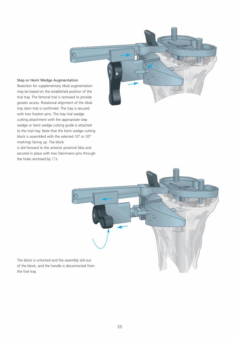
Step or Hemi Wedge Augmentation
Resection for supplementary tibial augmentation
may be based on the established position of the
trial tray. The femoral trial is removed to provide
greater access. Rotational alignment of the tibial
tray stem trial is confirmed. The tray is secured
with two fixation pins. The tray trial wedge
cutting attachment with the appropriate step
wedge or hemi wedge cutting guide is attached
to the trial tray. Note that the hemi wedge cutting
block is assembled with the selected 10° or 20°
markings facing up. The block
is slid forward to the anterior proximal tibia and
secured in place with two Steinmann pins through
the holes enclosed by ’s.
The block is unlocked and the assembly slid out
of the block, and the handle is disconnected from
the trial tray.
34
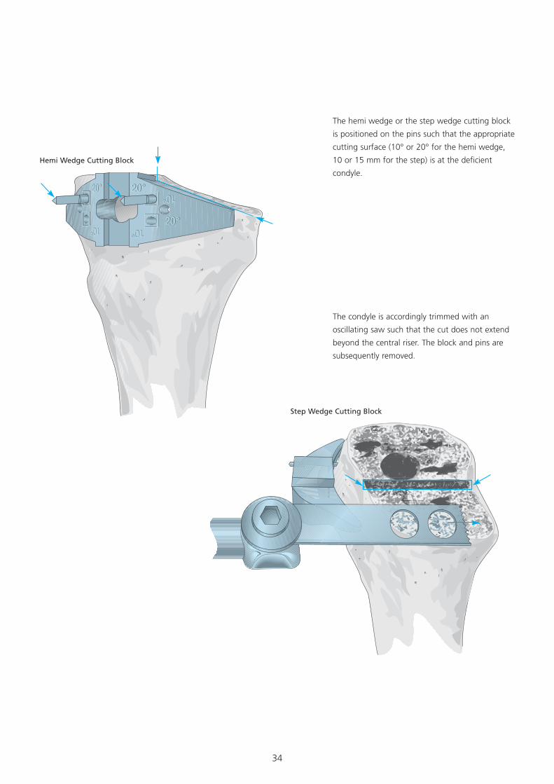
The hemi wedge or the step wedge cutting block
is positioned on the pins such that the appropriate
cutting surface (10° or 20° for the hemi wedge,
10 or 15 mm for the step) is at the deficient
condyle.
The condyle is accordingly trimmed with an
oscillating saw such that the cut does not extend
beyond the central riser. The block and pins are
subsequently removed.
Hemi Wedge Cutting Block
Step Wedge Cutting Block
35
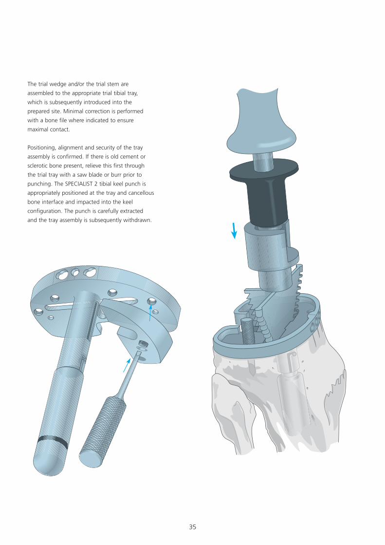
The trial wedge and/or the trial stem are
assembled to the appropriate trial tibial tray,
which is subsequently introduced into the
prepared site. Minimal correction is performed
with a bone file where indicated to ensure
maximal contact.
Positioning, alignment and security of the tray
assembly is confirmed. If there is old cement or
sclerotic bone present, relieve this first through
the trial tray with a saw blade or burr prior to
punching. The SPECIALIST 2 tibial keel punch is
appropriately positioned at the tray and cancellous
bone interface and impacted into the keel
configuration. The punch is carefully extracted
and the tray assembly is subsequently withdrawn.
36
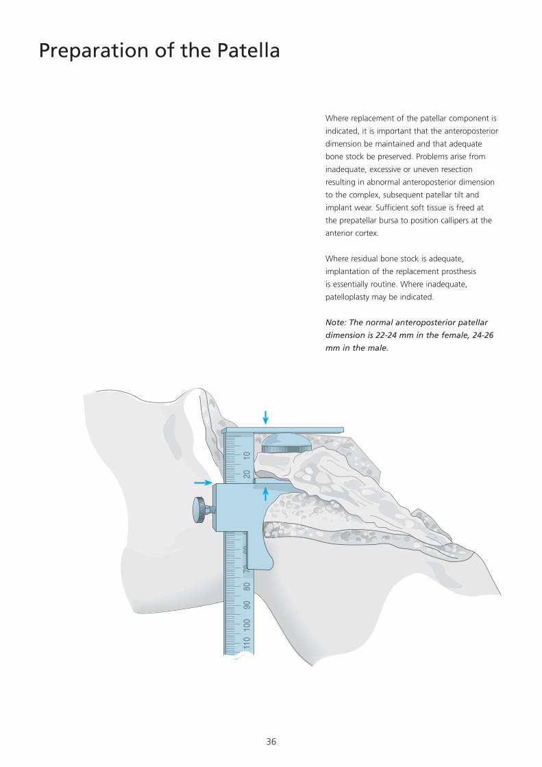
Preparation of the Patella
Where replacement of the patellar component is
indicated, it is important that the anteroposterior
dimension be maintained and that adequate
bone stock be preserved. Problems arise from
inadequate, excessive or uneven resection
resulting in abnormal anteroposterior dimension
to the complex, subsequent patellar tilt and
implant wear. Sufficient soft tissue is freed at
the prepatellar bursa to position callipers at the
anterior cortex.
Where residual bone stock is adequate,
implantation of the replacement prosthesis
is essentially routine. Where inadequate,
patelloplasty may be indicated.
Note: The normal anteroposterior patellar
dimension is 22-24 mm in the female, 24-26
mm in the male.
11
0 10
0 90
80
70
60
50
40
30
20
10
�0�
37
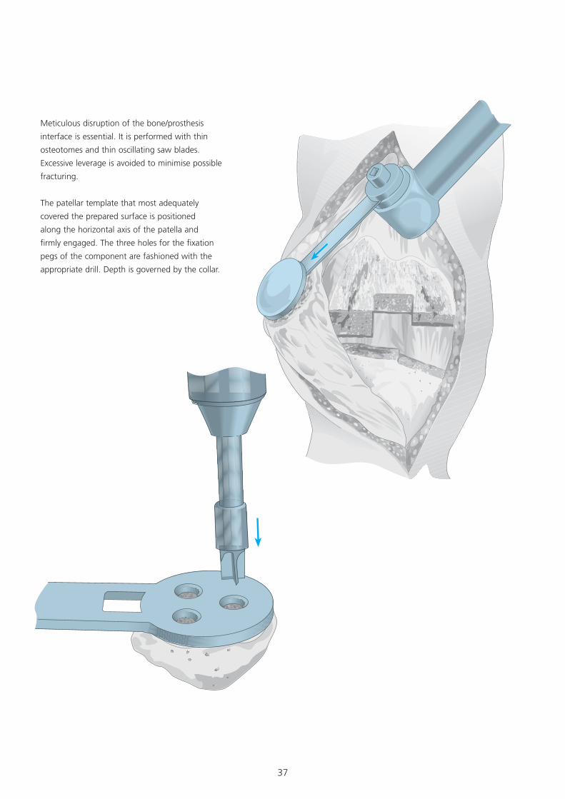
Meticulous disruption of the bone/prosthesis
interface is essential. It is performed with thin
osteotomes and thin oscillating saw blades.
Excessive leverage is avoided to minimise possible
fracturing.
The patellar template that most adequately
covered the prepared surface is positioned
along the horizontal axis of the patella and
firmly engaged. The three holes for the fixation
pegs of the component are fashioned with the
appropriate drill. Depth is governed by the collar.

38
Assembling the Prosthesis
The Tibial Component
The tibial stem extension is coupled to the
prosthetic tray, using the two appropriate
wrenches to ensure full engagement.
It is essential that the stem be locked in position
before the wedge/step augmentation unit is
assembled.
39
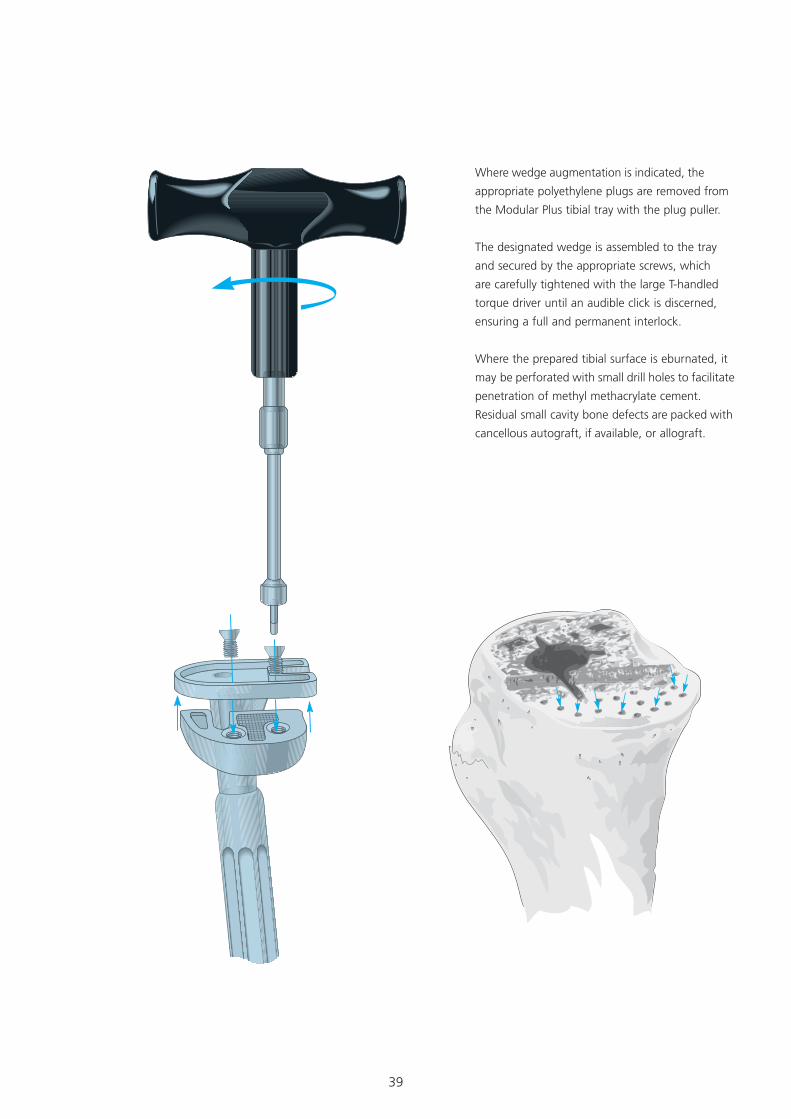
Where wedge augmentation is indicated, the
appropriate polyethylene plugs are removed from
the Modular Plus tibial tray with the plug puller.
The designated wedge is assembled to the tray
and secured by the appropriate screws, which
are carefully tightened with the large T-handled
torque driver until an audible click is discerned,
ensuring a full and permanent interlock.
Where the prepared tibial surface is eburnated, it
may be perforated with small drill holes to facilitate
penetration of methyl methacrylate cement.
Residual small cavity bone defects are packed with
cancellous autograft, if available, or allograft.
40
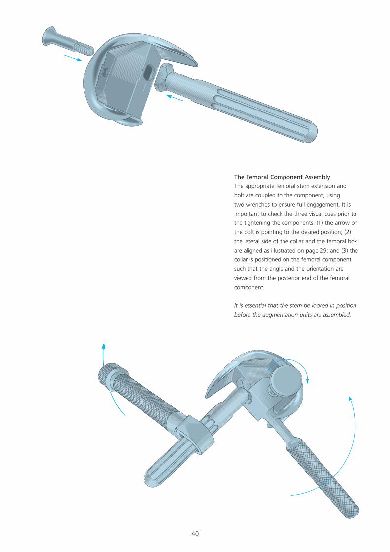
The Femoral Component Assembly
The appropriate femoral stem extension and
bolt are coupled to the component, using
two wrenches to ensure full engagement. It is
important to check the three visual cues prior to
the tightening the components: (1) the arrow on
the bolt is pointing to the desired position; (2)
the lateral side of the collar and the femoral box
are aligned as illustrated on page 29; and (3) the
collar is positioned on the femoral component
such that the angle and the orientation are
viewed from the posterior end of the femoral
component.
It is essential that the stem be locked in position
before the augmentation units are assembled.
41
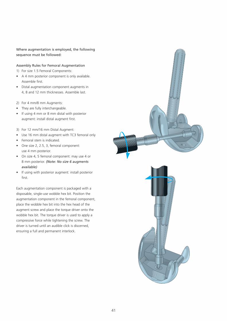
Where augmentation is employed, the following
sequence must be followed:
Assembly Rules for Femoral Augmentation
1) For size 1.5 Femoral Components:
• A 4 mm posterior component is only available.
Assemble first.
• Distal augmentation component augments in
4, 8 and 12 mm thicknesses. Assemble last.
2) For 4 mm/8 mm Augments:
• They are fully interchangeable.
• If using 4 mm or 8 mm distal with posterior
augment: install distal augment first.
3) For 12 mm/16 mm Distal Augment:
• Use 16 mm distal augment with TC3 femoral only
• Femoral stem is indicated.
• One size 2, 2.5, 3, femoral component:
use 4 mm posterior.
• On size 4, 5 femoral component: may use 4 or
8 mm posterior. (Note: No size 6 augments
available)
• If using with posterior augment: install posterior
first.
Each augmentation component is packaged with a
disposable, single-use wobble hex bit. Position the
augmentation component in the femoral component,
place the wobble hex bit into the hex head of the
augment screw and place the torque driver onto the
wobble hex bit. The torque driver is used to apply a
compressive force while tightening the screw. The
driver is turned until an audible click is discerned,
ensuring a full and permanent interlock.
42
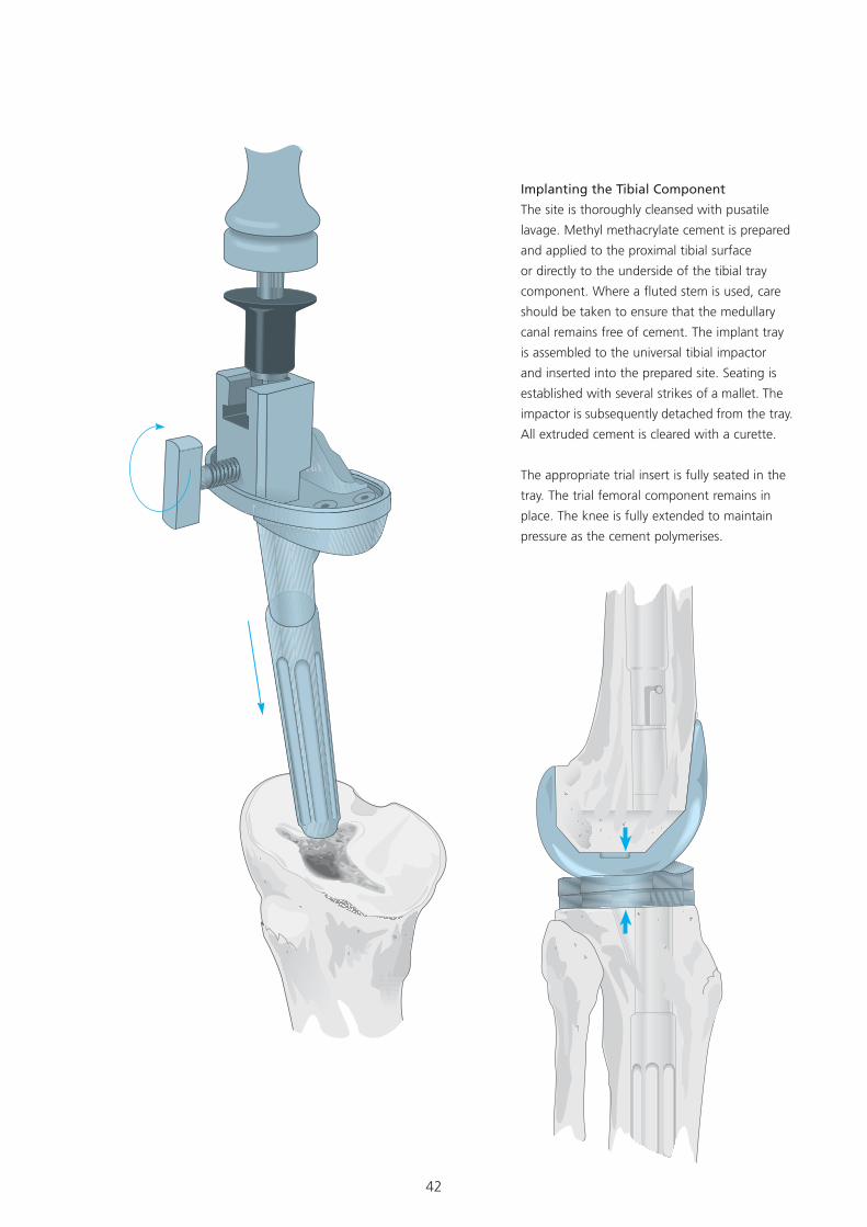
Implanting the Tibial Component
The site is thoroughly cleansed with pusatile
lavage. Methyl methacrylate cement is prepared
and applied to the proximal tibial surface
or directly to the underside of the tibial tray
component. Where a fluted stem is used, care
should be taken to ensure that the medullary
canal remains free of cement. The implant tray
is assembled to the universal tibial impactor
and inserted into the prepared site. Seating is
established with several strikes of a mallet. The
impactor is subsequently detached from the tray.
All extruded cement is cleared with a curette.
The appropriate trial insert is fully seated in the
tray. The trial femoral component remains in
place. The knee is fully extended to maintain
pressure as the cement polymerises.
43
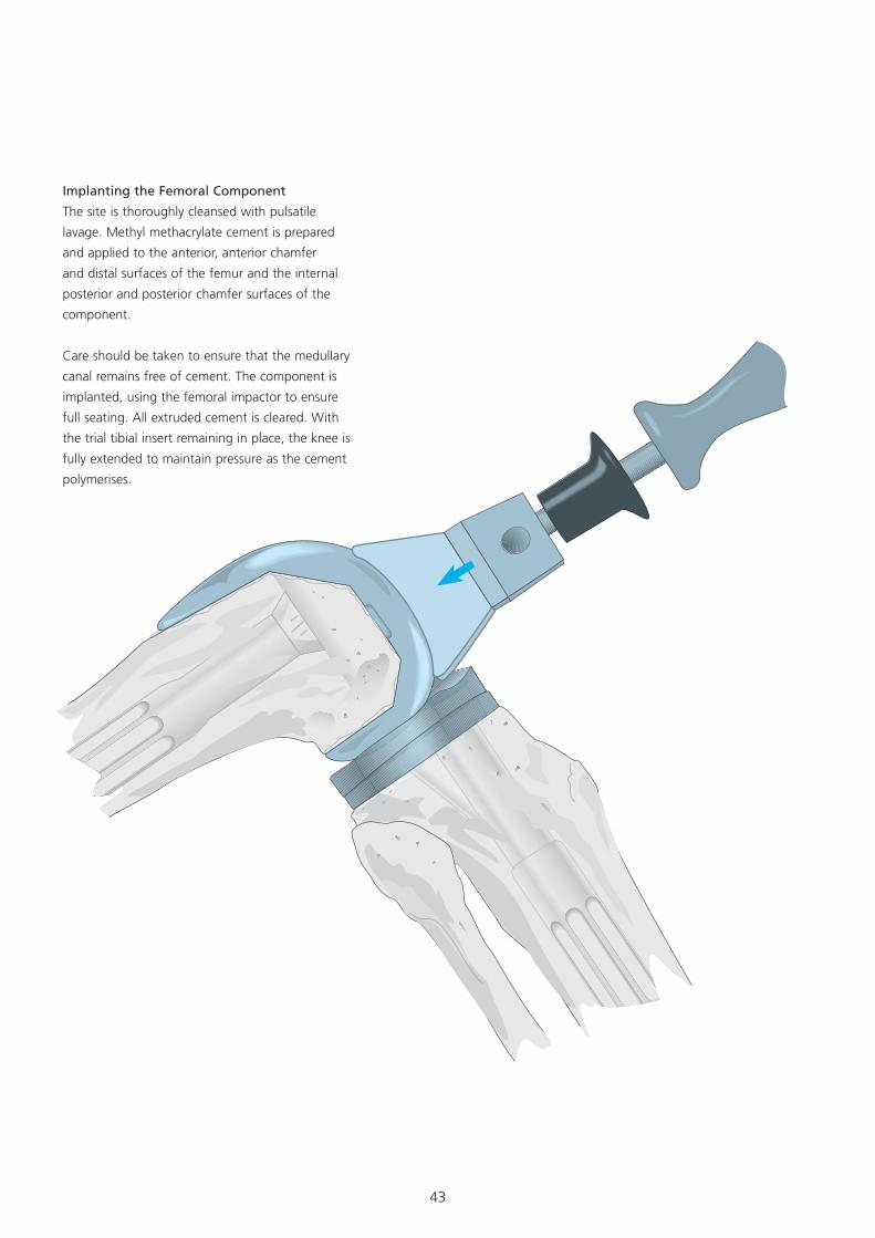
Implanting the Femoral Component
The site is thoroughly cleansed with pulsatile
lavage. Methyl methacrylate cement is prepared
and applied to the anterior, anterior chamfer
and distal surfaces of the femur and the internal
posterior and posterior chamfer surfaces of the
component.
Care should be taken to ensure that the medullary
canal remains free of cement. The component is
implanted, using the femoral impactor to ensure
full seating. All extruded cement is cleared. With
the trial tibial insert remaining in place, the knee is
fully extended to maintain pressure as the cement
polymerises.
44
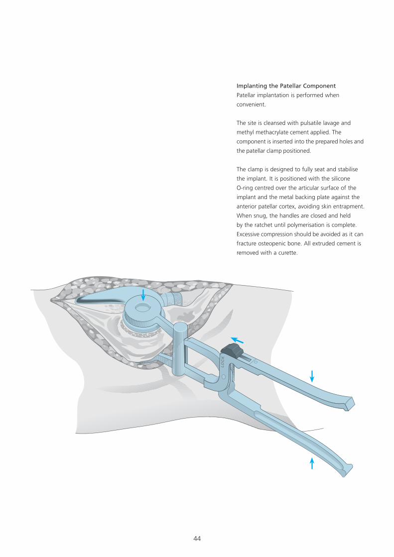
Implanting the Patellar Component
Patellar implantation is performed when
convenient.
The site is cleansed with pulsatile lavage and
methyl methacrylate cement applied. The
component is inserted into the prepared holes and
the patellar clamp positioned.
The clamp is designed to fully seat and stabilise
the implant. It is positioned with the silicone
O-ring centred over the articular surface of the
implant and the metal backing plate against the
anterior patellar cortex, avoiding skin entrapment.
When snug, the handles are closed and held
by the ratchet until polymerisation is complete.
Excessive compression should be avoided as it can
fracture osteopenic bone. All extruded cement is
removed with a curette.
45
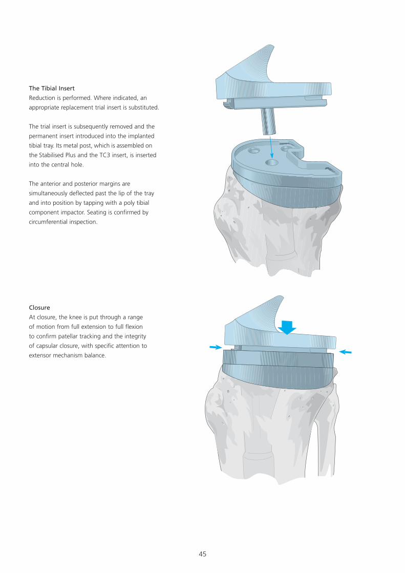
Closure
At closure, the knee is put through a range
of motion from full extension to full flexion
to confirm patellar tracking and the integrity
of capsular closure, with specific attention to
extensor mechanism balance.
The Tibial Insert
Reduction is performed. Where indicated, an
appropriate replacement trial insert is substituted.
The trial insert is subsequently removed and the
permanent insert introduced into the implanted
tibial tray. Its metal post, which is assembled on
the Stabilised Plus and the TC3 insert, is inserted
into the central hole.
The anterior and posterior margins are
simultaneously deflected past the lip of the tray
and into position by tapping with a poly tibial
component impactor. Seating is confirmed by
circumferential inspection.
46
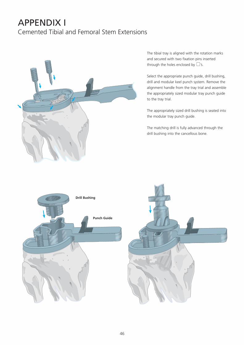
Cemented Tibial and Femoral Stem Extensions
Select the appropriate punch guide, drill bushing,
drill and modular keel punch system. Remove the
alignment handle from the tray trial and assemble
the appropriately sized modular tray punch guide
to the tray trial.
The appropriately sized drill bushing is seated into
the modular tray punch guide.
The matching drill is fully advanced through the
drill bushing into the cancellous bone.
The tibial tray is aligned with the rotation marks
and secured with two fixation pins inserted
through the holes enclosed by ’s.
APPENDIX I
Drill Bushing
Punch Guide
47
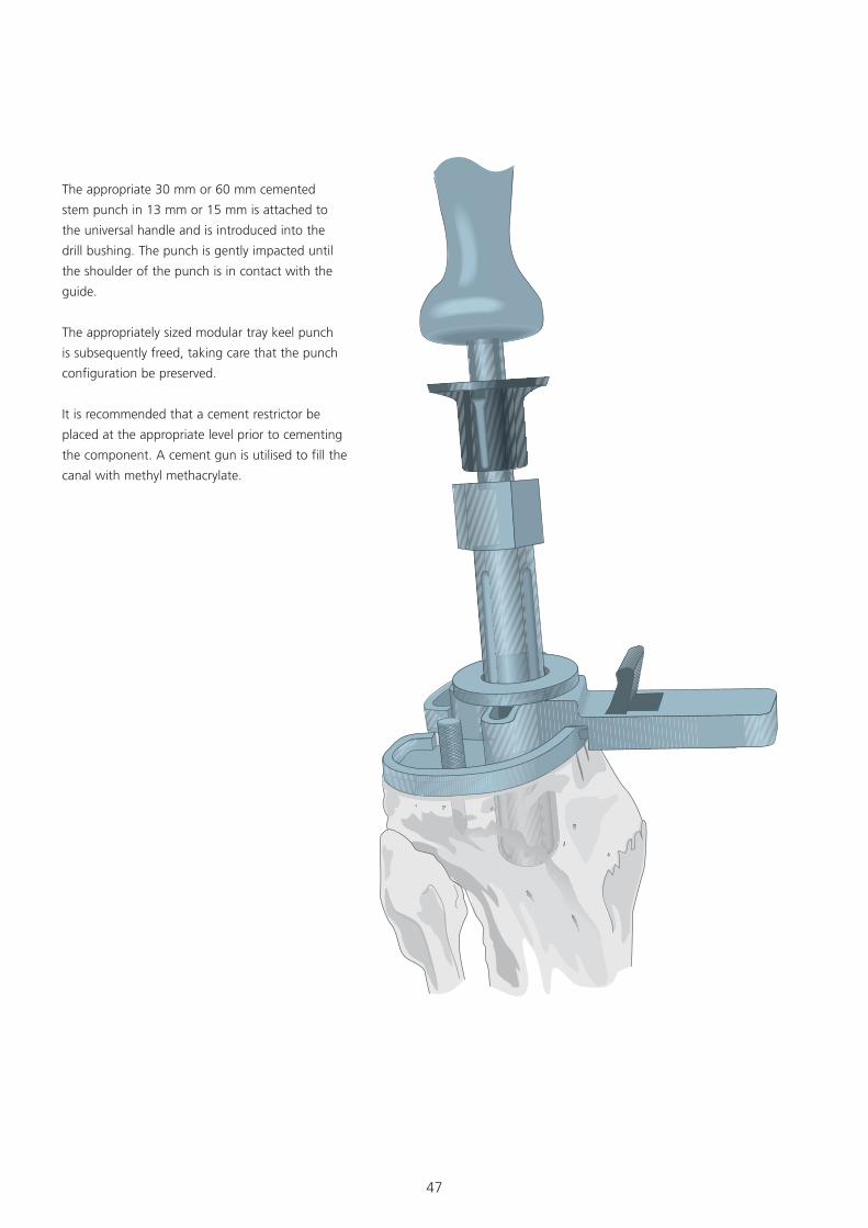
The appropriate 30 mm or 60 mm cemented
stem punch in 13 mm or 15 mm is attached to
the universal handle and is introduced into the
drill bushing. The punch is gently impacted until
the shoulder of the punch is in contact with the
guide.
The appropriately sized modular tray keel punch
is subsequently freed, taking care that the punch
configuration be preserved.
It is recommended that a cement restrictor be
placed at the appropriate level prior to cementing
the component. A cement gun is utilised to fill the
canal with methyl methacrylate.
48
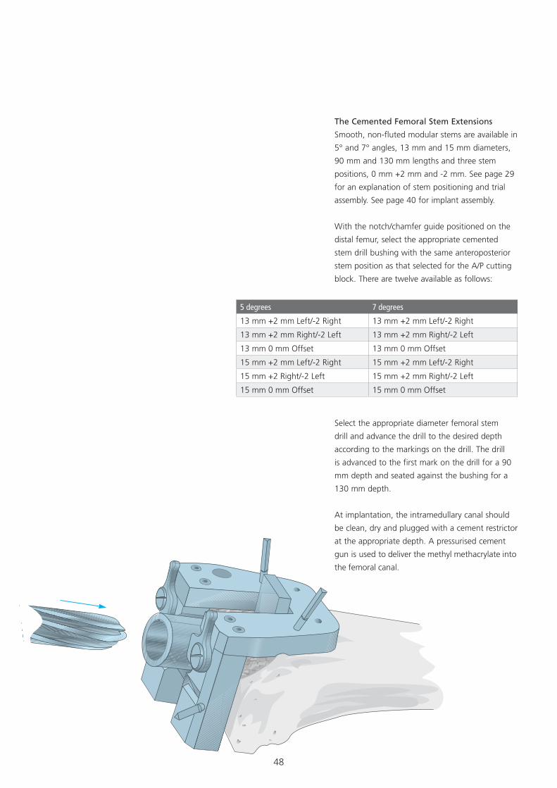
The Cemented Femoral Stem Extensions
Smooth, non-fluted modular stems are available in
5° and 7° angles, 13 mm and 15 mm diameters,
90 mm and 130 mm lengths and three stem
positions, 0 mm +2 mm and -2 mm. See page 29
for an explanation of stem positioning and trial
assembly. See page 40 for implant assembly.
With the notch/chamfer guide positioned on the
distal femur, select the appropriate cemented
stem drill bushing with the same anteroposterior
stem position as that selected for the A/P cutting
block. There are twelve available as follows:
5 degrees 7 degrees
13 mm +2 mm Left/-2 Right 13 mm +2 mm Left/-2 Right
13 mm +2 mm Right/-2 Left 13 mm +2 mm Right/-2 Left
13 mm 0 mm Offset 13 mm 0 mm Offset
15 mm +2 mm Left/-2 Right 15 mm +2 mm Left/-2 Right
15 mm +2 Right/-2 Left 15 mm +2 mm Right/-2 Left
15 mm 0 mm Offset 15 mm 0 mm Offset
Select the appropriate diameter femoral stem
drill and advance the drill to the desired depth
according to the markings on the drill. The drill
is advanced to the first mark on the drill for a 90
mm depth and seated against the bushing for a
130 mm depth.
At implantation, the intramedullary canal should
be clean, dry and plugged with a cement restrictor
at the appropriate depth. A pressurised cement
gun is used to deliver the methyl methacrylate into
the femoral canal.
49
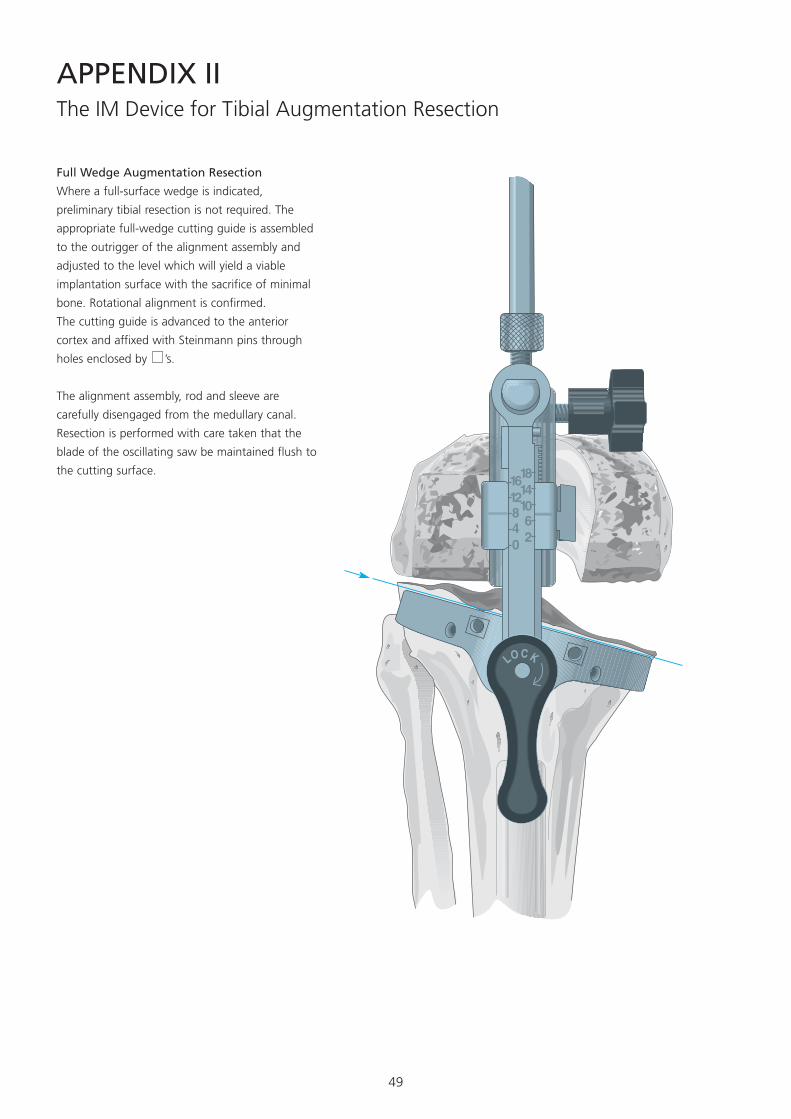
The IM Device for Tibial Augmentation Resection
Full Wedge Augmentation Resection
Where a full-surface wedge is indicated,
preliminary tibial resection is not required. The
appropriate full-wedge cutting guide is assembled
to the outrigger of the alignment assembly and
adjusted to the level which will yield a viable
implantation surface with the sacrifice of minimal
bone. Rotational alignment is confirmed.
The cutting guide is advanced to the anterior
cortex and affixed with Steinmann pins through
holes enclosed by ’s.
The alignment assembly, rod and sleeve are
carefully disengaged from the medullary canal.
Resection is performed with care taken that the
blade of the oscillating saw be maintained flush to
the cutting surface.
APPENDIX II

50
Step and Hemi Wedge Augmentation
Resection
The IM system was designed to control wedge
or step cuts directly from the tibial alignment
device. The Steinmann pins are withdrawn and
the cutting block removed. The alignment device
remains locked in position on the IM rod. The
wedge/step cutting block is assembled to the
outrigger with the appropriate cutting surface
(10° or 20° for the hemi, 10 or 15 mm for the
step) positioned at the more deficient condyle
at the same outrigger level employed for the
proximal tibial resection.
Resection for augmentation ideally should be
delayed until proper rotational alignment of the
tibial component is confirmed at trial reduction.
Steinmann pins are introduced for enhanced
fixation. Resection based on the appropriate
cutting surface configured to accept the
assembled augmented prosthesis.
Positioned for a Hemi Wedge Cut
Positioned for a Step Wedge Cut
51
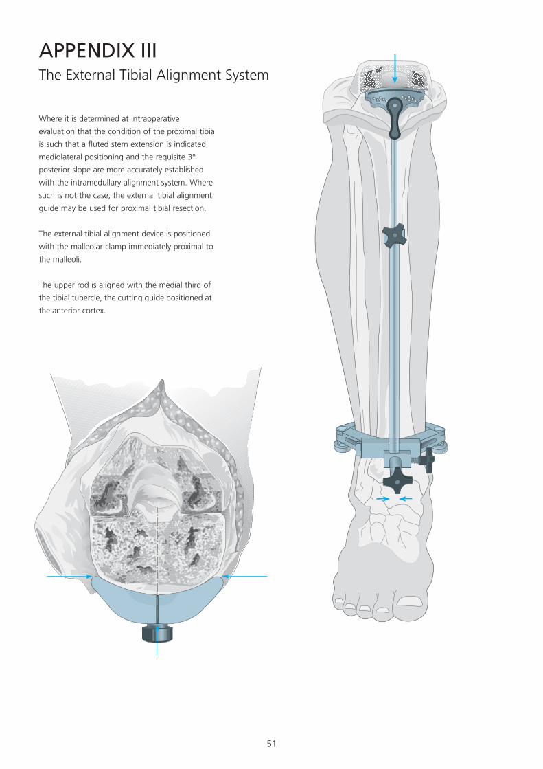
APPENDIX IIIThe External Tibial Alignment System
Where it is determined at intraoperative
evaluation that the condition of the proximal tibia
is such that a fluted stem extension is indicated,
mediolateral positioning and the requisite 3°
posterior slope are more accurately established
with the intramedullary alignment system. Where
such is not the case, the external tibial alignment
guide may be used for proximal tibial resection.
The external tibial alignment device is positioned
with the malleolar clamp immediately proximal to
the malleoli.
The upper rod is aligned with the medial third of
the tibial tubercle, the cutting guide positioned at
the anterior cortex.
52
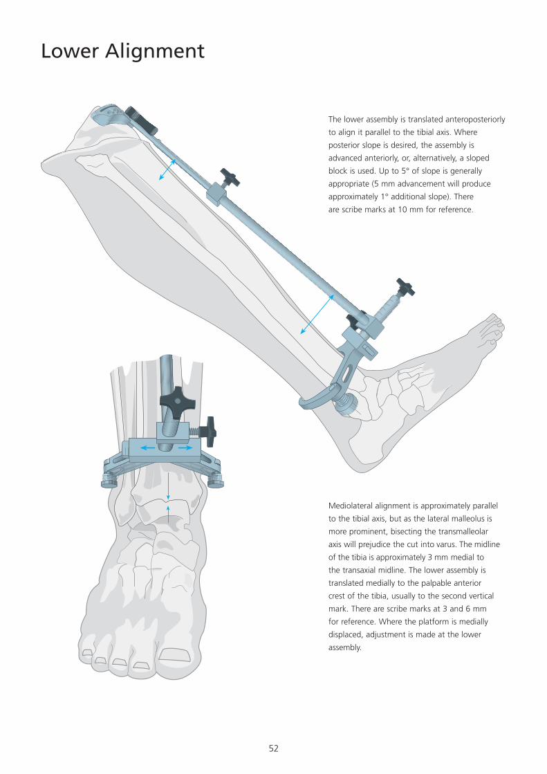
Lower Alignment
The lower assembly is translated anteroposteriorly
to align it parallel to the tibial axis. Where
posterior slope is desired, the assembly is
advanced anteriorly, or, alternatively, a sloped
block is used. Up to 5° of slope is generally
appropriate (5 mm advancement will produce
approximately 1° additional slope). There
are scribe marks at 10 mm for reference.
Mediolateral alignment is approximately parallel
to the tibial axis, but as the lateral malleolus is
more prominent, bisecting the transmalleolar
axis will prejudice the cut into varus. The midline
of the tibia is approximately 3 mm medial to
the transaxial midline. The lower assembly is
translated medially to the palpable anterior
crest of the tibia, usually to the second vertical
mark. There are scribe marks at 3 and 6 mm
for reference. Where the platform is medially
displaced, adjustment is made at the lower
assembly.
53
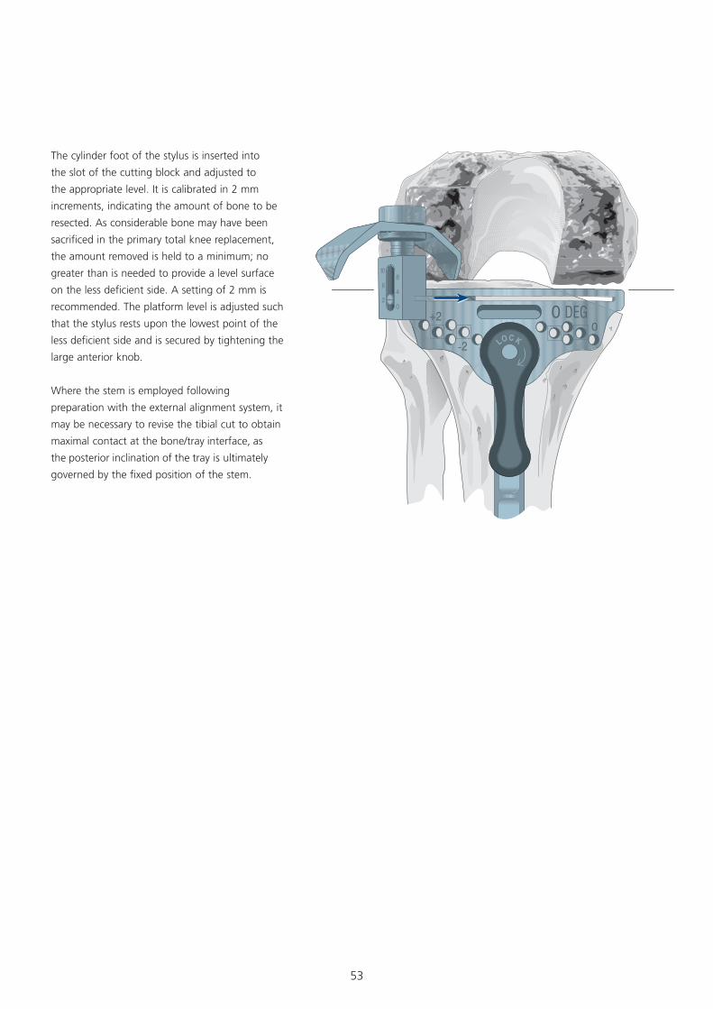
The cylinder foot of the stylus is inserted into
the slot of the cutting block and adjusted to
the appropriate level. It is calibrated in 2 mm
increments, indicating the amount of bone to be
resected. As considerable bone may have been
sacrificed in the primary total knee replacement,
the amount removed is held to a minimum; no
greater than is needed to provide a level surface
on the less deficient side. A setting of 2 mm is
recommended. The platform level is adjusted such
that the stylus rests upon the lowest point of the
less deficient side and is secured by tightening the
large anterior knob.
Where the stem is employed following
preparation with the external alignment system, it
may be necessary to revise the tibial cut to obtain
maximal contact at the bone/tray interface, as
the posterior inclination of the tray is ultimately
governed by the fixed position of the stem.
54
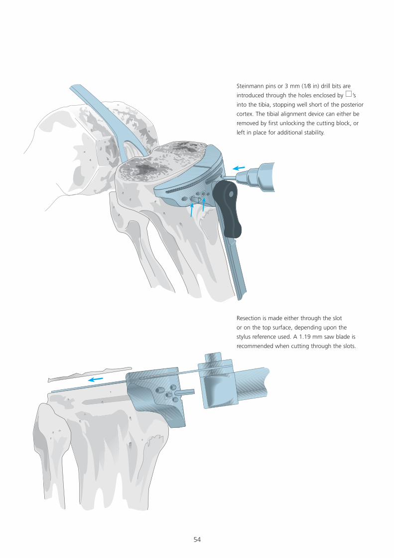
Steinmann pins or 3 mm (1⁄8 in) drill bits are
introduced through the holes enclosed by ’s
into the tibia, stopping well short of the posterior
cortex. The tibial alignment device can either be
removed by first unlocking the cutting block, or
left in place for additional stability.
Resection is made either through the slot
or on the top surface, depending upon the
stylus reference used. A 1.19 mm saw blade is
recommended when cutting through the slots.
55
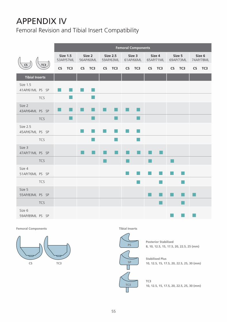
APPENDIX IVFemoral Revision and Tibial Insert Compatibility
CS TC3
PS
SP
TC3TC3
10, 12.5, 15, 17.5, 20, 22.5, 25, 30 (mm)
Stabilised Plus
10, 12.5, 15, 17.5, 20, 22.5, 25, 30 (mm)
Posterior Stabilised
8, 10, 12.5, 15, 17.5, 20, 22.5, 25 (mm)
Femoral Components Tibial Inserts
Femoral Components
Size 1.5 53AP/57ML
Size 2 56AP/60ML
Size 2.5 59AP/63ML
Size 3 61AP/66ML
Size 4 65AP/71ML
Size 5 69AP/73ML
Size 6 74AP/78ML
CS TC3 CS TC3 CS TC3 CS TC3 CS TC3 CS TC3 CS TC3
Tibial Inserts
Size 1.5
41AP/61ML PS SP
TCS
Size 2
43AP/64ML PS SP
TCS
Size 2.5
45AP/67ML PS SP
TCS
Size 3
47AP/71ML PS SP
TCS
Size 4
51AP/76ML PS SP
TCS
Size 5
55AP/83ML PS SP
TCS
Size 6
59AP/89ML PS SP
CS TC3

56
Notes

57
Notes

58
Notes

59

60
©DePuy International Ltd. and DePuy Orthopaedics, Inc. 2012. All rights reserved.
www.depuy.com
0086
DePuy International LtdSt Anthony’s RoadLeeds LS11 8DTEnglandTel: +44 (0)113 387 7800Fax: +44 (0)113 387 7890
DePuy Orthopaedics, Inc. 700 Orthopaedic DriveWarsaw, IN 46581-0988USATel: +1 (800) 366 8143Fax: +1 (574) 267 7196
This publication is not intended for distribution in the USA.
DePuy Orthopaedics EMEA is a trading division of DePuy International Limited.Registered Office: St. Anthony’s Road, Leeds LS11 8DT, EnglandRegistered in England No. 3319712
9461-99-000 version 3 Issued: 12/12
CA#DPEM/ORT/1112/0357