Embed Size (px)
Citation preview

Fixed WiMax Design Library
May 2007

Notice
The information contained in this document is subject to change without notice.
Agilent Technologies makes no warranty of any kind with regard to this material, including, but not limited to, the implied warranties of merchantability and fitness for a particular purpose. Agilent Technologies shall not be liable for errors contained herein or for incidental or consequential damages in connection with the furnishing, performance, or use of this material.
Warranty
A copy of the specific warranty terms that apply to this software product is available upon request from your Agilent Technologies representative.
Restricted Rights Legend
Use, duplication or disclosure by the U. S. Government is subject to restrictions as set forth in subparagraph (c) (1) (ii) of the Rights in Technical Data and Computer Software clause at DFARS 252.227-7013 for DoD agencies, and subparagraphs (c) (1) and (c) (2) of the Commercial Computer Software Restricted Rights clause at FAR 52.227-19 for other agencies.
© Agilent Technologies, Inc. 1983-2007. 395 Page Mill Road, Palo Alto, CA 94304 U.S.A.
Acknowledgments
Mentor Graphics is a trademark of Mentor Graphics Corporation in the U.S. and other countries.
Microsoft®, Windows®, MS Windows®, Windows NT®, and MS-DOS® are U.S. registered trademarks of Microsoft Corporation.
Pentium® is a U.S. registered trademark of Intel Corporation.
PostScript® and Acrobat® are trademarks of Adobe Systems Incorporated.
UNIX® is a registered trademark of the Open Group.
Java™ is a U.S. trademark of Sun Microsystems, Inc.
SystemC® is a registered trademark of Open SystemC Initiative, Inc. in the United States and other countries and is used with permission.
MATLAB® is a U.S. registered trademark of The Math Works, Inc.
ii
Contents1 Fixed WiMAX Design Library
WiMAX Systems....................................................................................................... 1-1Component Libraries ................................................................................................ 1-4
Channel Components......................................................................................... 1-4Channel Coding Components ............................................................................ 1-4Measurement Component.................................................................................. 1-4Multiplex Components ........................................................................................ 1-5Receiver Components ........................................................................................ 1-5Signal Source Components................................................................................ 1-6
Design Examples...................................................................................................... 1-7Glossary of Terms..................................................................................................... 1-9References ............................................................................................................... 1-9
2 WMAN Channel ComponentsWMAN_FWA_Channel (WMAN FWA Channel) ....................................................... 2-2
3 WMAN Channel Coding ComponentsWMAN_CRC_Coder (WMAN CRC Coder) .............................................................. 3-2WMAN_FEC (WMAN Forward Error Correction Coder)........................................... 3-5WMAN_FEC_Decoder (WMAN Forward Error Correction Decoder) ....................... 3-9WMAN_Puncturer (WMAN Puncturer) ..................................................................... 3-11WMAN_RSDecoder (WMAN Reed-Solomon Decoder) ........................................... 3-13WMAN_Scrambler (WMAN Scrambler).................................................................... 3-18
4 WMAN Measurement ComponentsWMAN_DL_Constellation_RF (WMAN Downlink Constellation Measurement)....... 4-2WMAN_DL_RF_CCDF_FD (WMAN Downlink RF CCDF FD) ................................. 4-6WMAN_DL_SpecFlat (WMAN Downlink Spectral Flatness Measurement).............. 4-10WMAN_RF_CCDF (WMAN RF CCDF).................................................................... 4-13WMAN_UL_Constellation_RF (WMAN Uplink Constellation Measurement) ........... 4-15WMAN_UL_RF_CCDF_FD (WMAN Uplink RF CCDF FD)...................................... 4-19WMAN_UL_SpecFlat (WMAN Uplink SpecFlat)....................................................... 4-23
5 WMAN Multiplex ComponentsWMAN_BurstWoFEC (WMAN Burst Without FEC Generator) ................................ 5-2WMAN_DemuxOFDMSym (WMAN OFDM demultiplexer) ...................................... 5-5WMAN_DL_DemuxBurst (WMAN Downlink Demultiplex Burst) .............................. 5-7WMAN_DL_DemuxBurst_FD (WMAN Downlink Demultiplex Burst FD).................. 5-10WMAN_DL_MuxBurst (WMAN Downlink Multiplex Burst) ....................................... 5-13WMAN_DL_MuxBurst_FD (WMAN Downlink Multiplex Burst FD)........................... 5-16WMAN_DL_MuxFrame (WMAN Downlink Multiplex Frame) ................................... 5-19
iii
WMAN_UL_DemuxBurst (WMAN Uplink burst demultiplexer)................................. 5-25WMAN_UL_MuxBurst (WMAN Uplink MuxBurst) .................................................... 5-28WMAN_UL_MuxFrame (WMAN Uplink Frame Multiplexer)..................................... 5-31WMAN_UL_MuxOFDMSym (WMAN Uplink MuxOFDMSym).................................. 5-37
6 WMAN Receiver ComponentsWMAN_Demapper (WMAN Demapper)................................................................... 6-2WMAN_DL_ChEstimator (WMAN Downlink Channel Estimator)............................. 6-5WMAN_DL_DemuxFrame (WMAN Downlink Demultiplex Frame) .......................... 6-8WMAN_DL_DemuxFrame_FD (WMAN Downlink Demultiplex Frame FD).............. 6-14WMAN_DL_FrameSync (WMAN Downlink Frame Synchronizer) ........................... 6-22WMAN_DL_FreqSync (WMAN Downlink Frequency Synchronizer)........................ 6-27WMAN_DL_PhaseTracker (WMAN Downlink Phase Tracker)................................. 6-31WMAN_DL_Receiver (Downlink baseband receiver)............................................... 6-34WMAN_DL_Receiver_RF (WMAN Downlink Receiver RF) ..................................... 6-42WMAN_DL_Rx_FD (WMAN DL Receiver with Frame Duration) ............................. 6-52WMAN_DL_Rx_FD_RF (WMAN DL Receiver RF with Frame Duration)................. 6-61WMAN_UL_ChEstimator (WMAN Uplink Channel Estimator) ................................. 6-72WMAN_UL_DemuxFrame (WMAN Uplink Frame Demultiplexer)............................ 6-77WMAN_UL_DemuxFrame_FD (WMAN Uplink Demultiplexer Frame FD) ............... 6-83WMAN_UL_FrameSync (WMAN Uplink Subframe Synchronizer)........................... 6-90WMAN_UL_FreqSync (WMAN Uplink Frequency Synchronizer) ............................ 6-97WMAN_UL_PhaseTracker (WMAN Uplink Phase Tracker) ..................................... 6-103WMAN_UL_Receiver (WMAN Uplink Receiver) ...................................................... 6-107WMAN_UL_Receiver_RF (WMAN Uplink Receiver RF).......................................... 6-117WMAN_UL_Rx_FD (WMAN Uplink Receiver with Frame Duration) ........................ 6-129WMAN_UL_Rx_FD_RF (WMAN UL Receiver RF with Frame Duration)................. 6-139
7 WMAN Signal Source ComponentsWMAN_BrdcstMessage (WMAN Broadcast Message)............................................ 7-2WMAN_DataPattern (WMAN Data Pattern) ............................................................. 7-6WMAN_DCD (WMAN DCD)..................................................................................... 7-9WMAN_DL_MAP (WMAN Downlink MAP)............................................................... 7-11WMAN_DL_Pilot (WMAN Downlink Pilot Generator) ............................................... 7-14WMAN_DL_SignalSrc (WMAN Downlink Signal Source) ........................................ 7-17WMAN_DL_SignalSrc_RF (WMAN Downlink Signal Source RF)............................ 7-24WMAN_DL_Src_FD (WMAN DL Signal Source with FrameDuration) ..................... 7-33WMAN_DL_Src_FD_RF (WMAN DL Source RF with FrameDuration).................... 7-43WMAN_DLFP (WMAN Downlink Frame Prefix) ....................................................... 7-54WMAN_MACHeader (WMAN MAC Header)............................................................ 7-57WMAN_MACPDU (WMAN MAC PDU) .................................................................... 7-59WMAN_Preamble (WMAN Preamble Generator) .................................................... 7-61WMAN_UCD (WMAN UCD)..................................................................................... 7-64
iv
WMAN_UL_MAP (WMAN Uplink MAP) ................................................................... 7-66WMAN_UL_Pilot (WMAN Uplink Pilot Generator).................................................... 7-69WMAN_UL_SignalSrc (WMAN Uplink Signal Source) ............................................. 7-73WMAN_UL_SignalSrc_RF (WMAN Uplink Signal Source RF) ................................ 7-83WMAN_UL_Src_FD (WMAN Uplink Signal Source with Frame Duration)............... 7-95WMAN_UL_Src_FD_RF (WMAN UL Source RF with Frame Duration)................... 7-107
8 WMAN Design ExamplesWMAN OFDM Transmitter Design Examples........................................................... 8-1
Downlink Transmitter Error Vector Magnitude Measurement............................. 8-1Downlink Transmitter Spectral Flatness Measurement ...................................... 8-4WMAN OFDM Downlink Transmitter Waveform Measurement.......................... 8-7Uplink Transmitter Error Vector Magnitude Measurement ................................. 8-10
WMAN OFDM Receiver Design Examples .............................................................. 8-14Downlink BER and PER Measurement on AWGN Channel............................... 8-14Downlink Receiver Sensitivity Measurement ..................................................... 8-16Uplink BER and PER Measurement on SUI Fading Channel ............................ 8-18WMAN OFDM Uplink Receiver Adjacent and Alternate Channel Rejection....... 8-21
WMAN OFDM FrameDuration Design Examples..................................................... 8-24Downlink BER and PER Measurement on SUI Fading Channel........................ 8-25Downlink Transmitter Error Vector Magnitude Measurement with FrameDuration8-27WMAN OFDM Downlink Transmitter Waveform Measurement with Frame Duration8-30Uplink BER and PER Measurement on AWGN Channel with FrameDuration... 8-34Uplink Transmitter Subchannel Error Vector Magnitude Measurement with
FrameDuration ................................................................................................. 8-36Index
v

vi
Chapter 1: Fixed WiMAX Design LibraryThe Agilent EEsof Fixed WiMAX wireless design library (WDL) is for the WiMAX OFDM (802.16-2004) market. This wireless design library follows IEEE Std 802.16-2004 and IEEE P802.16-2004/Cor1/D5. The design library focuses on WirelessMAN-OFDM PHY (section 8.3) in IEEE Std 802.16-2004 and is intended to be a baseline system for designers to get an idea of what a nominal or ideal system performance would be. Evaluations can be made regarding degraded system performance due to system impairments that may include non-ideal component performance.
WiMAX SystemsWhile wireless connectivity options have expanded rapidly in recent years, wireless network access is available now only in limited physical areas. Internet and internet users need broadband access that extends over longer distances to more locations. The industry solution is the Worldwide Interoperability for Microwave Access (WiMAX) standard, developed to create certified standards-based products from a wide range of vendors.
WiMAX, a data-on-the-go alternative to cable and DSL, is a standards-based broadband wireless access technology for enabling the last-mile delivery of information. WiMAX will provide fixed, nomadic, portable and, eventually, mobile wireless broadband connectivity without the need for direct line-of-sight connection between a base station and a subscriber station. In a typical cell radius deployment of 3 to 10 Km, WiMAX-certified systems can be expected to support capacity of up to 40 Mbps per channel, for fixed and portable access applications. This is enough bandwidth to simultaneously support hundreds of businesses with T-1 speed connectivity and thousands of residences with DSL speed connectivity. Mobile network deployments are expected to provide up to 15 Mbps of capacity within a typical cell-radius deployment of up to 3 Km. It is expected that WiMAX technology will be incorporated in notebook computers and PDAs starting as early as the end of 2006, enabling urban areas and cities to become MetroZones for portable outdoor broadband wireless access. WiMAX technology has the potential to enable service carriers to converge the all-IP-based network for triple-play services such as data, voice, and video.
The IEEE 802.16 standard originally specified an operating frequency band from 10 to 66 GHz. The 802.16-2004 supports fixed broadband wireless access for both licensed and unlicensed spectra in the 2-to-11-GHz range. However, the 802.16e amendment is under development to address mobile broadband wireless access.
In addition to supporting the 2-to-11-GHz frequency range, the 802.16-2004 standard supports three physical layers (PHYs). The mandatory PHY mode is 256-point FFT Orthogonal Frequency
WiMAX Systems 1-1
Fixed WiMAX Design Library
Division Multiplexing (OFDM). The other two PHY modes are Single Carrier (SC) and 2048 Orthogonal Frequency Division Multiple Access (OFDMA) modes. The corresponding European standardize ETSI HiperMAN standard defines a single PHY mode identical to the 256 OFDM mode in the 802.16-2004 standard.
Because the goal of WiMAX is to promote the interoperability of equipment based on either the 802.16-2004 or HiperMAN standards, the forum has chosen to support the 256 OFDM mode exclusively. To ensure worldwide interoperability, the WiMAX Forum will only certify equipment supporting that particular PHY mode.
WiFi 802.11a and 802.11g also use OFDM and have established an excellent performance record for robust wireless networking. However, WiFi uses 64 OFDM. The number before OFDM refers to the number of carriers that can be used in the overall modulation scheme. The much greater number of carriers for WiMAX helps achieve greater range because a receiver using 256 OFDM can tolerate delay spreads up to 10 times greater than systems using 64 OFDM. Also, 256 OFDM provides good non-line-of-sight capability.
This Fixed WiMAX just supports WirelessMAN-OFDM PHY (256-point FFT OFDM) in IEEE Std 802.16-2004.
Major specifications for the WirelessMAN-OFDM PHY physical layer are listed in Table 1-1.
1-2 WiMAX Systems
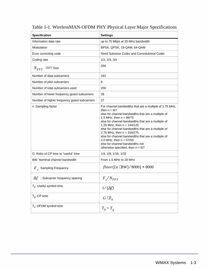
Table 1-1. WirelessMAN-OFDM PHY Physical Layer Major Specifications
Specification Settings
Information data rate up to 75 Mbps at 20 MHz bandwidth
Modulation BPSK, QPSK, 16-QAM, 64-QAM
Error correcting code Reed Solomon Coder and Convolutional Coder
Coding rate 1/2, 2/3, 3/4
:FFT Size 256
Number of data subcarriers 192
Number of pilot subcarriers 8
Number of total subcarriers used 200
Number of lower frequency guard subcarriers 28
Number of higher frequency guard subcarriers 27
n :Sampling factor For channel bandwidths that are a multiple of 1.75 MHz, then n = 8/7else for channel bandwidths that are a multiple of 1.5 MHz, then n = 86/75else for channel bandwidths that are a multiple of 1.25 MHz, then n = 144/125else for channel bandwidths that are a multiple of 2.75 MHz, then n = 316/275else for channel bandwidths that are a multiple of 2.0 MHz, then n = 57/50else for channel bandwidths nototherwise specified, then n = 8/7
G: Ratio of CP time to “useful” time 1/4, 1/8, 1/16, 1/32
BW: Nominal channel bandwidth From 1.5 MHz to 28 MHz
: Sampling Frequency
: Subcarrier frequency spacing
Tb: Useful symbol time
Tg: CP time
Ts: OFDM symbol time
NFFT
Fsfloor n BW⋅( ) 8000⁄( ) 8000×
∆f Fs NFFT⁄
1 f∆( )⁄
G Tb⋅
Tb Tg+
WiMAX Systems 1-3
Fixed WiMAX Design Library
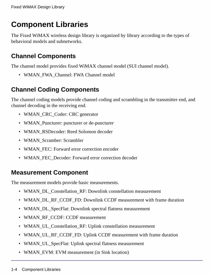
Component LibrariesThe Fixed WiMAX wireless design library is organized by library according to the types of behavioral models and subnetworks.
Channel Components
The channel model provides fixed WiMAX channel model (SUI channel model).
• WMAN_FWA_Channel: FWA Channel model
Channel Coding Components
The channel coding models provide channel coding and scrambling in the transmitter end, and channel decoding in the receiving end.
• WMAN_CRC_Coder: CRC generator
• WMAN_Puncturer: puncturer or de-puncturer
• WMAN_RSDecoder: Reed Solomon decoder
• WMAN_Scramber: Scrambler
• WMAN_FEC: Forward error correction encoder
• WMAN_FEC_Decoder: Forward error correction decoder
Measurement Component
The measurement models provide basic measurements.
• WMAN_DL_Constellation_RF: Downlink constellation measurement
• WMAN_DL_RF_CCDF_FD: Downlink CCDF measurement with frame duration
• WMAN_DL_SpecFlat: Downlink spectral flatness measurement
• WMAN_RF_CCDF: CCDF measurement
• WMAN_UL_Constellation_RF: Uplink constellation measurement
• WMAN_UL_RF_CCDF_FD: Uplink CCDF measurement with frame duration
• WMAN_UL_SpecFlat: Uplink spectral flatness measurement
• WMAN_EVM: EVM measurement (in Sink location)
1-4 Component Libraries
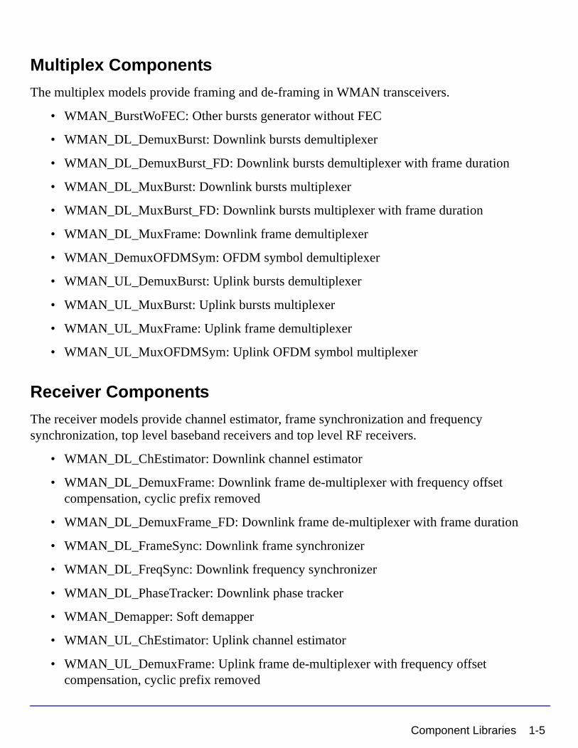
Multiplex Components
The multiplex models provide framing and de-framing in WMAN transceivers.
• WMAN_BurstWoFEC: Other bursts generator without FEC
• WMAN_DL_DemuxBurst: Downlink bursts demultiplexer
• WMAN_DL_DemuxBurst_FD: Downlink bursts demultiplexer with frame duration
• WMAN_DL_MuxBurst: Downlink bursts multiplexer
• WMAN_DL_MuxBurst_FD: Downlink bursts multiplexer with frame duration
• WMAN_DL_MuxFrame: Downlink frame demultiplexer
• WMAN_DemuxOFDMSym: OFDM symbol demultiplexer
• WMAN_UL_DemuxBurst: Uplink bursts demultiplexer
• WMAN_UL_MuxBurst: Uplink bursts multiplexer
• WMAN_UL_MuxFrame: Uplink frame demultiplexer
• WMAN_UL_MuxOFDMSym: Uplink OFDM symbol multiplexer
Receiver Components
The receiver models provide channel estimator, frame synchronization and frequency synchronization, top level baseband receivers and top level RF receivers.
• WMAN_DL_ChEstimator: Downlink channel estimator
• WMAN_DL_DemuxFrame: Downlink frame de-multiplexer with frequency offset compensation, cyclic prefix removed
• WMAN_DL_DemuxFrame_FD: Downlink frame de-multiplexer with frame duration
• WMAN_DL_FrameSync: Downlink frame synchronizer
• WMAN_DL_FreqSync: Downlink frequency synchronizer
• WMAN_DL_PhaseTracker: Downlink phase tracker
• WMAN_Demapper: Soft demapper
• WMAN_UL_ChEstimator: Uplink channel estimator
• WMAN_UL_DemuxFrame: Uplink frame de-multiplexer with frequency offset compensation, cyclic prefix removed
Component Libraries 1-5
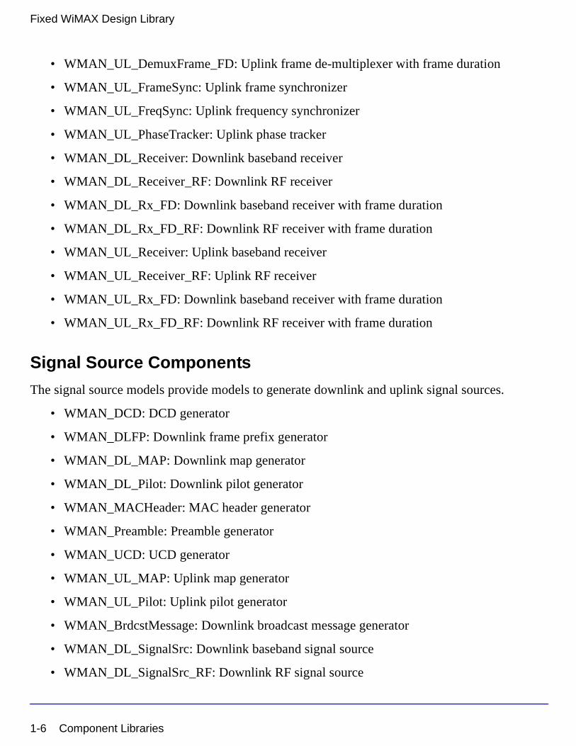
Fixed WiMAX Design Library
• WMAN_UL_DemuxFrame_FD: Uplink frame de-multiplexer with frame duration
• WMAN_UL_FrameSync: Uplink frame synchronizer
• WMAN_UL_FreqSync: Uplink frequency synchronizer
• WMAN_UL_PhaseTracker: Uplink phase tracker
• WMAN_DL_Receiver: Downlink baseband receiver
• WMAN_DL_Receiver_RF: Downlink RF receiver
• WMAN_DL_Rx_FD: Downlink baseband receiver with frame duration
• WMAN_DL_Rx_FD_RF: Downlink RF receiver with frame duration
• WMAN_UL_Receiver: Uplink baseband receiver
• WMAN_UL_Receiver_RF: Uplink RF receiver
• WMAN_UL_Rx_FD: Downlink baseband receiver with frame duration
• WMAN_UL_Rx_FD_RF: Downlink RF receiver with frame duration
Signal Source Components
The signal source models provide models to generate downlink and uplink signal sources.
• WMAN_DCD: DCD generator
• WMAN_DLFP: Downlink frame prefix generator
• WMAN_DL_MAP: Downlink map generator
• WMAN_DL_Pilot: Downlink pilot generator
• WMAN_MACHeader: MAC header generator
• WMAN_Preamble: Preamble generator
• WMAN_UCD: UCD generator
• WMAN_UL_MAP: Uplink map generator
• WMAN_UL_Pilot: Uplink pilot generator
• WMAN_BrdcstMessage: Downlink broadcast message generator
• WMAN_DL_SignalSrc: Downlink baseband signal source
• WMAN_DL_SignalSrc_RF: Downlink RF signal source
1-6 Component Libraries
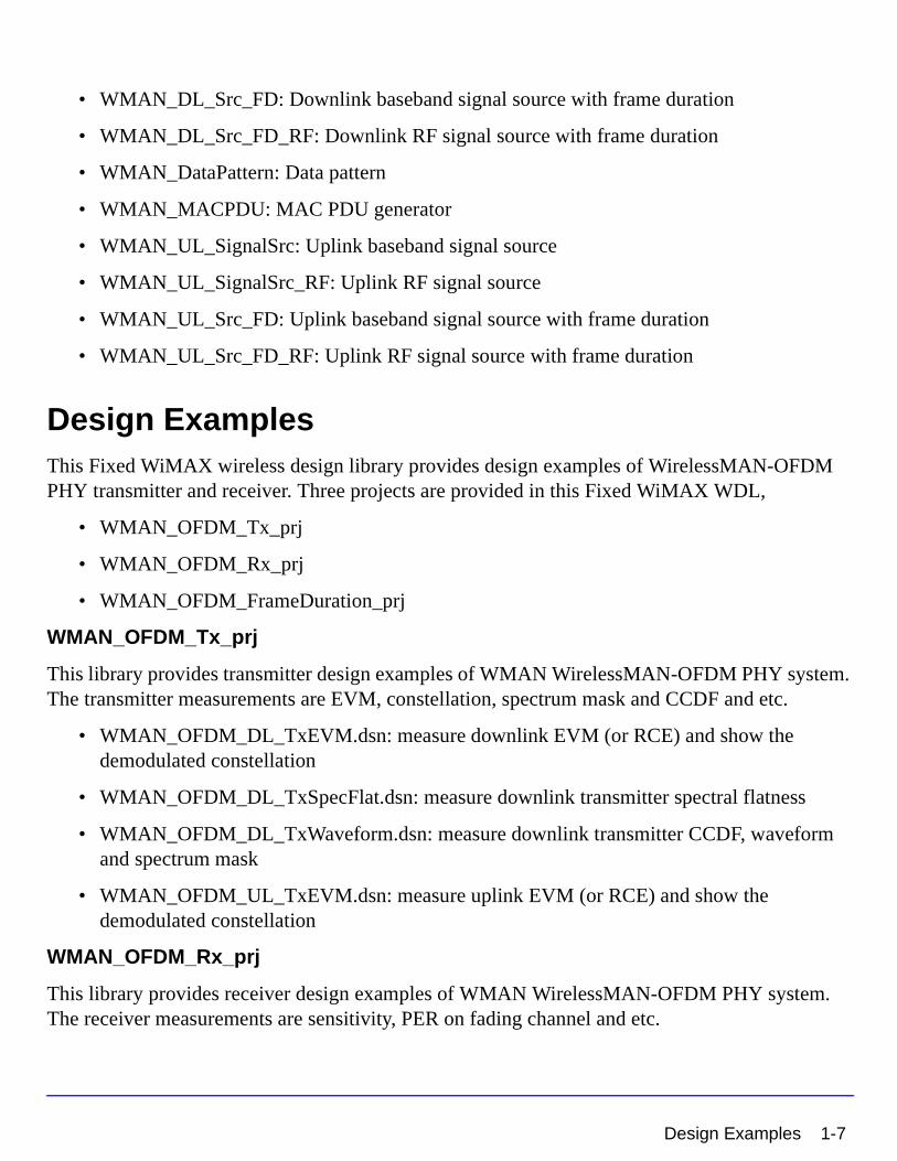
• WMAN_DL_Src_FD: Downlink baseband signal source with frame duration
• WMAN_DL_Src_FD_RF: Downlink RF signal source with frame duration
• WMAN_DataPattern: Data pattern
• WMAN_MACPDU: MAC PDU generator
• WMAN_UL_SignalSrc: Uplink baseband signal source
• WMAN_UL_SignalSrc_RF: Uplink RF signal source
• WMAN_UL_Src_FD: Uplink baseband signal source with frame duration
• WMAN_UL_Src_FD_RF: Uplink RF signal source with frame duration
Design ExamplesThis Fixed WiMAX wireless design library provides design examples of WirelessMAN-OFDM PHY transmitter and receiver. Three projects are provided in this Fixed WiMAX WDL,
• WMAN_OFDM_Tx_prj
• WMAN_OFDM_Rx_prj
• WMAN_OFDM_FrameDuration_prj
WMAN_OFDM_Tx_prj
This library provides transmitter design examples of WMAN WirelessMAN-OFDM PHY system. The transmitter measurements are EVM, constellation, spectrum mask and CCDF and etc.
• WMAN_OFDM_DL_TxEVM.dsn: measure downlink EVM (or RCE) and show the demodulated constellation
• WMAN_OFDM_DL_TxSpecFlat.dsn: measure downlink transmitter spectral flatness
• WMAN_OFDM_DL_TxWaveform.dsn: measure downlink transmitter CCDF, waveform and spectrum mask
• WMAN_OFDM_UL_TxEVM.dsn: measure uplink EVM (or RCE) and show the demodulated constellation
WMAN_OFDM_Rx_prj
This library provides receiver design examples of WMAN WirelessMAN-OFDM PHY system. The receiver measurements are sensitivity, PER on fading channel and etc.
Design Examples 1-7
Fixed WiMAX Design Library
• WMAN_OFDM_DL_AWGN_BER.dsn: measure downlink BER/PER in AWGN environment
• WMAN_OFDM_DL_RxSentivity.dsn: measure downlink receiver minimum input level sensitivity
• WMAN_OFDM_UL_Fading_BER.dsn: measure uplink BER/PER in fading channel
• WMAN_OFDM_UL_RxAdjCh.dsn: measure uplink receiver adjacent and alternate channel rejection
WMAN_OFDM_FrameDuration_prj
This project provides some design examples of transmitter and receiver to support frame duration in WirelessMAN-OFDM PHY system.
• WMAN_OFDM_DL_Fading_BER_FD.dsn: measure downlink BER/PER in fading channel with frame duration
• WMAN_OFDM_DL_TxEVM_FD.dsn: measure downlink EVM (or RCE) and show the demodulated constellation with frame duration
• WMAN_OFDM_DL_TxWaveform_FD.dsn: measure downlink transmitter CCDF, waveform and spectrum mask with frame duration
• WMAN_OFDM_UL_AWGN_BER_FD.dsn: measure uplink BER/PER in AWGN environment with frame duration
• WMAN_OFDM_UL_SubCh_TxEVM_FD.dsn: measure uplink EVM (or RCE) and show the demodulated constellation with subchannelization
1-8 Design Examples
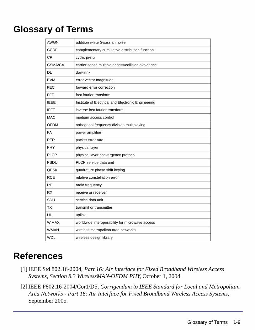
Glossary of Terms
References[1] IEEE Std 802.16-2004, Part 16: Air Interface for Fixed Broadband Wireless Access
Systems, Section 8.3 WirelessMAN-OFDM PHY, October 1, 2004.
[2] IEEE P802.16-2004/Cor1/D5, Corrigendum to IEEE Standard for Local and Metropolitan Area Networks - Part 16: Air Interface for Fixed Broadband Wireless Access Systems, September 2005.
AWGN addition white Gaussian noise
CCDF complementary cumulative distribution function
CP cyclic prefix
CSMA/CA carrier sense multiple access/collision avoidance
DL downlink
EVM error vector magnitude
FEC forward error correction
FFT fast fourier transform
IEEE Institute of Electrical and Electronic Engineering
IFFT inverse fast fourier transform
MAC medium access control
OFDM orthogonal frequency division multiplexing
PA power amplifier
PER packet error rate
PHY physical layer
PLCP physical layer convergence protocol
PSDU PLCP service data unit
QPSK quadrature phase shift keying
RCE relative constellation error
RF radio frequency
RX receive or receiver
SDU service data unit
TX transmit or transmitter
UL uplink
WiMAX worldwide interoperability for microwave access
WMAN wireless metropolitan area networks
WDL wireless design library
Glossary of Terms 1-9

Fixed WiMAX Design Library
1-10 References
Chapter 2: WMAN Channel ComponentsThe channel model provides fixed WiMAX channel model (SUI channel model).
• WMAN_FWA_Channel: FWA Channel model
2-1
WMAN Channel Components
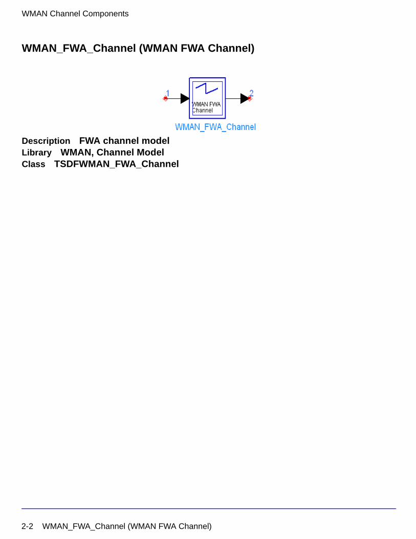
WMAN_FWA_Channel (WMAN FWA Channel)
Description FWA channel modelLibrary WMAN, Channel ModelClass TSDFWMAN_FWA_Channel
2-2 WMAN_FWA_Channel (WMAN FWA Channel)
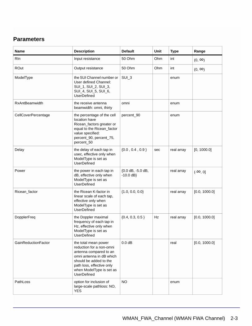
Parameters
Name Description Default Unit Type Range
RIn Input resistance 50 Ohm Ohm int (0, ∞)
ROut Output resistance 50 Ohm Ohm int (0, ∞)
ModelType the SUI Channel number or User defined Channel: SUI_1, SUI_2, SUI_3, SUI_4, SUI_5, SUI_6, UserDefined
SUI_3 enum
RxAntBeamwidth the receive antenna beamwidth: omni, thirty
omni enum
CellCoverPercentage the percentage of the cell location have Ricean_factors greater or equal to the Ricean_factor value specified: percent_90, percent_75, percent_50
percent_90 enum
Delay the delay of each tap in usec, effective only when ModelType is set as UserDefined
{0.0 , 0.4 , 0.9 } sec real array [0, 1000.0]
Power the power in each tap in dB, effective only when ModelType is set as UserDefined
{0.0 dB, -5.0 dB, -10.0 dB}
real array (-∞, 0]
Ricean_factor the Ricean K-factor in linear scale of each tap, effective only when ModelType is set as UserDefined
{1.0, 0.0, 0.0} real array [0.0, 1000.0]
DopplerFreq the Doppler maximal frequency of each tap in Hz, effective only when ModelType is set as UserDefined
{0.4, 0.3, 0.5 } Hz real array [0.0, 1000.0]
GainReductionFactor the total mean power reduction for a non-omni antenna compared to an omni antenna in dB which should be added to the path loss, effective only when ModelType is set as UserDefined
0.0 dB real [0.0, 1000.0]
PathLoss option for inclusion of large-scale pathloss: NO, YES
NO enum
WMAN_FWA_Channel (WMAN FWA Channel) 2-3
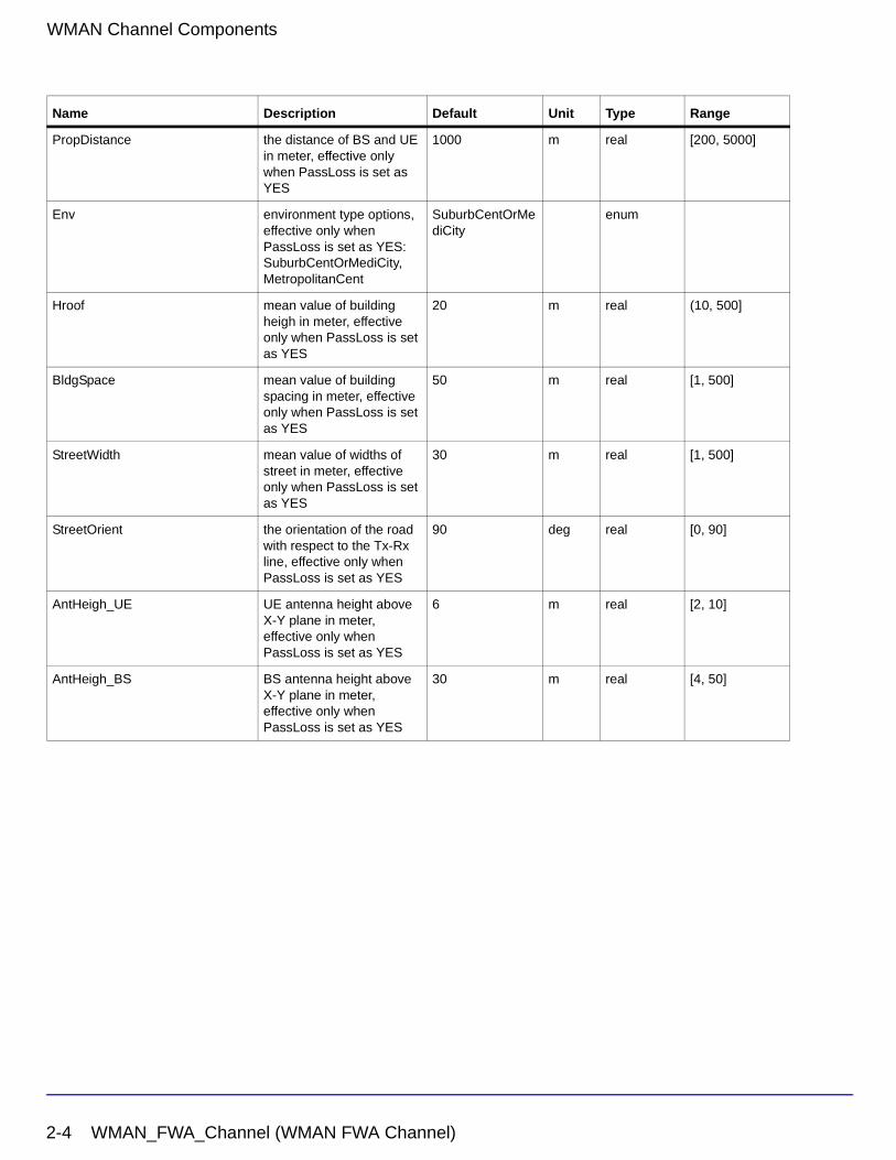
WMAN Channel Components
PropDistance the distance of BS and UE in meter, effective only when PassLoss is set as YES
1000 m real [200, 5000]
Env environment type options, effective only when PassLoss is set as YES: SuburbCentOrMediCity, MetropolitanCent
SuburbCentOrMediCity
enum
Hroof mean value of building heigh in meter, effective only when PassLoss is set as YES
20 m real (10, 500]
BldgSpace mean value of building spacing in meter, effective only when PassLoss is set as YES
50 m real [1, 500]
StreetWidth mean value of widths of street in meter, effective only when PassLoss is set as YES
30 m real [1, 500]
StreetOrient the orientation of the road with respect to the Tx-Rx line, effective only when PassLoss is set as YES
90 deg real [0, 90]
AntHeigh_UE UE antenna height above X-Y plane in meter, effective only when PassLoss is set as YES
6 m real [2, 10]
AntHeigh_BS BS antenna height above X-Y plane in meter, effective only when PassLoss is set as YES
30 m real [4, 50]
Name Description Default Unit Type Range
2-4 WMAN_FWA_Channel (WMAN FWA Channel)
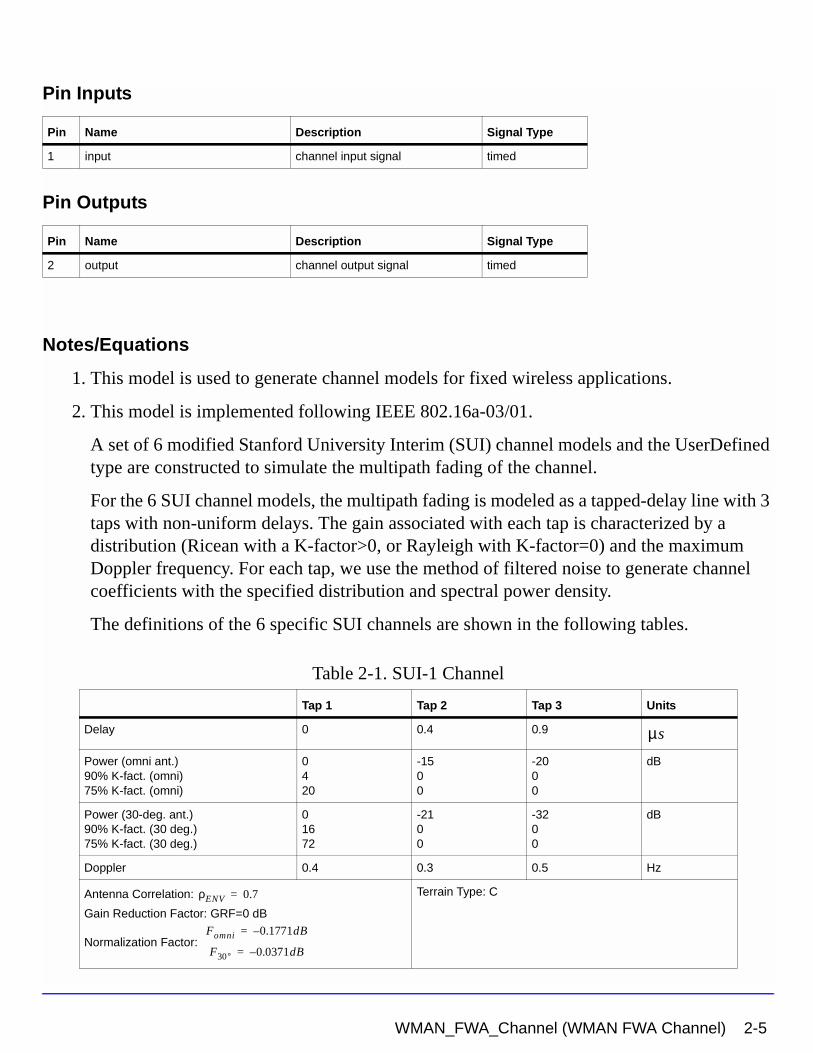
Pin Inputs
Pin Outputs
Notes/Equations
1. This model is used to generate channel models for fixed wireless applications.
2. This model is implemented following IEEE 802.16a-03/01.
A set of 6 modified Stanford University Interim (SUI) channel models and the UserDefined type are constructed to simulate the multipath fading of the channel.
For the 6 SUI channel models, the multipath fading is modeled as a tapped-delay line with 3 taps with non-uniform delays. The gain associated with each tap is characterized by a distribution (Ricean with a K-factor>0, or Rayleigh with K-factor=0) and the maximum Doppler frequency. For each tap, we use the method of filtered noise to generate channel coefficients with the specified distribution and spectral power density.
The definitions of the 6 specific SUI channels are shown in the following tables.
Pin Name Description Signal Type
1 input channel input signal timed
Pin Name Description Signal Type
2 output channel output signal timed
Table 2-1. SUI-1 Channel
Tap 1 Tap 2 Tap 3 Units
Delay 0 0.4 0.9
Power (omni ant.)90% K-fact. (omni)75% K-fact. (omni)
0420
-1500
-2000
dB
Power (30-deg. ant.)90% K-fact. (30 deg.)75% K-fact. (30 deg.)
01672
-2100
-3200
dB
Doppler 0.4 0.3 0.5 Hz
Antenna Correlation:
Gain Reduction Factor: GRF=0 dB
Normalization Factor:
Terrain Type: C
µs
ρENV 0.7=
Fomni 0.1771dB–=
F30° 0.0371dB–=
WMAN_FWA_Channel (WMAN FWA Channel) 2-5
WMAN Channel Components
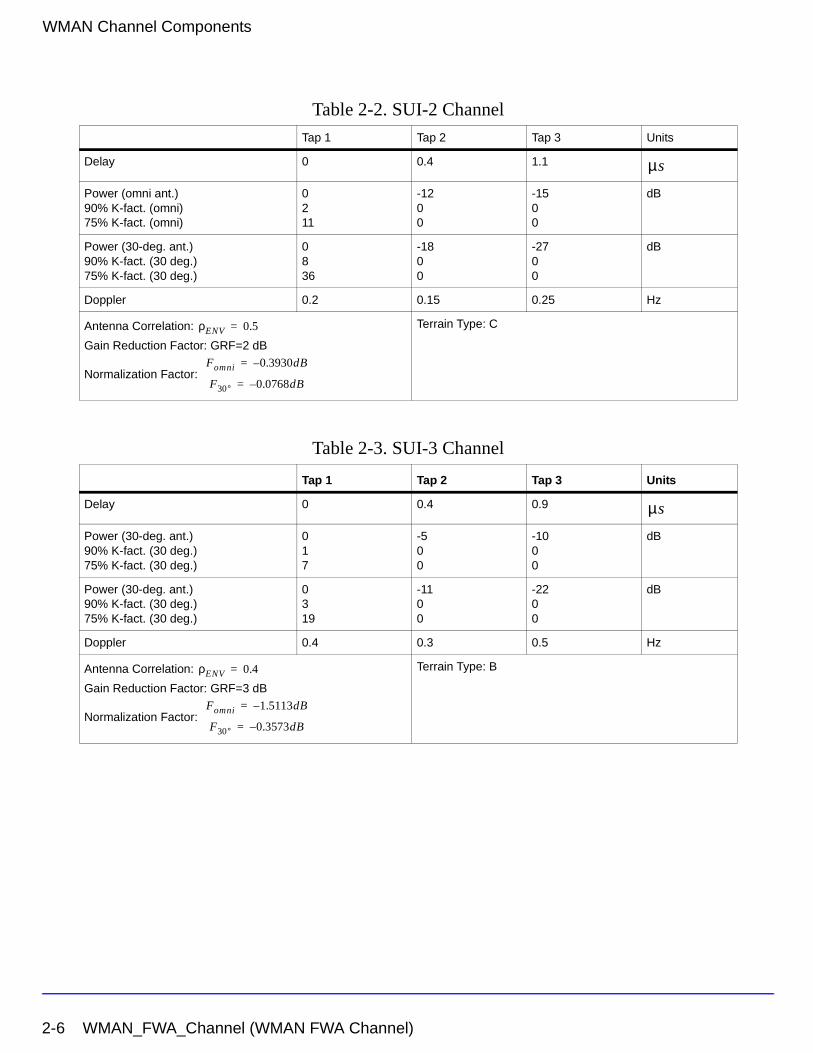
Table 2-2. SUI-2 Channel
Tap 1 Tap 2 Tap 3 Units
Delay 0 0.4 1.1
Power (omni ant.)90% K-fact. (omni)75% K-fact. (omni)
0211
-1200
-1500
dB
Power (30-deg. ant.)90% K-fact. (30 deg.)75% K-fact. (30 deg.)
0836
-1800
-2700
dB
Doppler 0.2 0.15 0.25 Hz
Antenna Correlation:
Gain Reduction Factor: GRF=2 dB
Normalization Factor:
Terrain Type: C
Table 2-3. SUI-3 Channel
Tap 1 Tap 2 Tap 3 Units
Delay 0 0.4 0.9
Power (30-deg. ant.)90% K-fact. (30 deg.)75% K-fact. (30 deg.)
017
-500
-1000
dB
Power (30-deg. ant.)90% K-fact. (30 deg.)75% K-fact. (30 deg.)
0319
-1100
-2200
dB
Doppler 0.4 0.3 0.5 Hz
Antenna Correlation:
Gain Reduction Factor: GRF=3 dB
Normalization Factor:
Terrain Type: B
µs
ρENV 0.5=
Fomni 0.3930dB–=
F30° 0.0768dB–=
µs
ρENV 0.4=
Fomni 1.5113dB–=
F30° 0.3573dB–=
2-6 WMAN_FWA_Channel (WMAN FWA Channel)
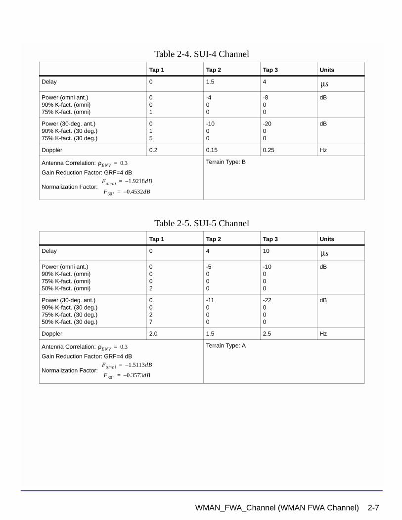
Table 2-4. SUI-4 Channel
Tap 1 Tap 2 Tap 3 Units
Delay 0 1.5 4
Power (omni ant.)90% K-fact. (omni)75% K-fact. (omni)
001
-400
-800
dB
Power (30-deg. ant.)90% K-fact. (30 deg.)75% K-fact. (30 deg.)
015
-1000
-2000
dB
Doppler 0.2 0.15 0.25 Hz
Antenna Correlation:
Gain Reduction Factor: GRF=4 dB
Normalization Factor:
Terrain Type: B
Table 2-5. SUI-5 Channel
Tap 1 Tap 2 Tap 3 Units
Delay 0 4 10
Power (omni ant.)90% K-fact. (omni)75% K-fact. (omni)50% K-fact. (omni)
0002
-5000
-10000
dB
Power (30-deg. ant.)90% K-fact. (30 deg.)75% K-fact. (30 deg.)50% K-fact. (30 deg.)
0027
-11000
-22000
dB
Doppler 2.0 1.5 2.5 Hz
Antenna Correlation:
Gain Reduction Factor: GRF=4 dB
Normalization Factor:
Terrain Type: A
µs
ρENV 0.3=
Fomni 1.9218dB–=
F30° 0.4532dB–=
µs
ρENV 0.3=
Fomni 1.5113dB–=
F30° 0.3573dB–=
WMAN_FWA_Channel (WMAN FWA Channel) 2-7
WMAN Channel Components
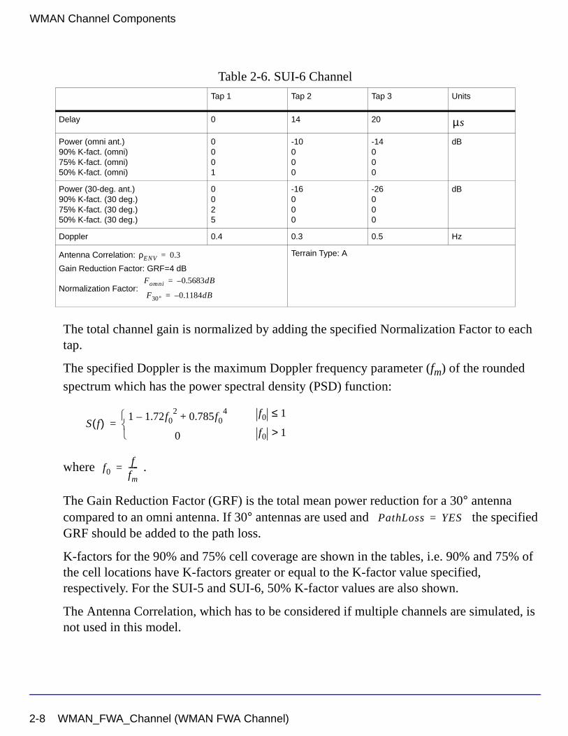
The total channel gain is normalized by adding the specified Normalization Factor to each tap.
The specified Doppler is the maximum Doppler frequency parameter (fm) of the rounded
spectrum which has the power spectral density (PSD) function:
where .
The Gain Reduction Factor (GRF) is the total mean power reduction for a 30° antenna compared to an omni antenna. If 30° antennas are used and the specified GRF should be added to the path loss.
K-factors for the 90% and 75% cell coverage are shown in the tables, i.e. 90% and 75% of the cell locations have K-factors greater or equal to the K-factor value specified, respectively. For the SUI-5 and SUI-6, 50% K-factor values are also shown.
The Antenna Correlation, which has to be considered if multiple channels are simulated, is not used in this model.
Table 2-6. SUI-6 Channel
Tap 1 Tap 2 Tap 3 Units
Delay 0 14 20
Power (omni ant.)90% K-fact. (omni)75% K-fact. (omni)50% K-fact. (omni)
0001
-10000
-14000
dB
Power (30-deg. ant.)90% K-fact. (30 deg.)75% K-fact. (30 deg.)50% K-fact. (30 deg.)
0025
-16000
-26000
dB
Doppler 0.4 0.3 0.5 Hz
Antenna Correlation:
Gain Reduction Factor: GRF=4 dB
Normalization Factor:
Terrain Type: A
µs
ρENV 0.3=
Fomni 0.5683dB–=
F30° 0.1184dB–=
S f( ) 1 1.72f02
– 0.785f04
+
0
=f0 1≤
f0 1>
f0f
fm-----=
PathLoss YES=
2-8 WMAN_FWA_Channel (WMAN FWA Channel)
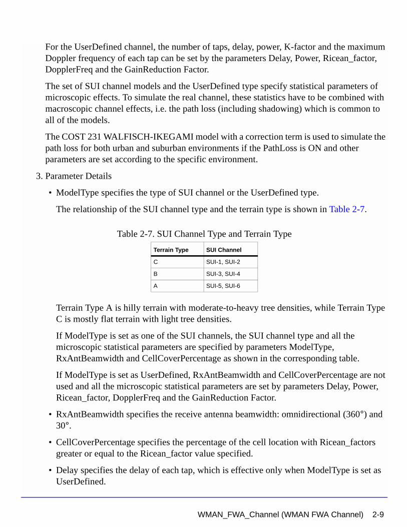
For the UserDefined channel, the number of taps, delay, power, K-factor and the maximum Doppler frequency of each tap can be set by the parameters Delay, Power, Ricean_factor, DopplerFreq and the GainReduction Factor.
The set of SUI channel models and the UserDefined type specify statistical parameters of microscopic effects. To simulate the real channel, these statistics have to be combined with macroscopic channel effects, i.e. the path loss (including shadowing) which is common to all of the models.
The COST 231 WALFISCH-IKEGAMI model with a correction term is used to simulate the path loss for both urban and suburban environments if the PathLoss is ON and other parameters are set according to the specific environment.
3. Parameter Details
• ModelType specifies the type of SUI channel or the UserDefined type.
The relationship of the SUI channel type and the terrain type is shown in Table 2-7.
Terrain Type A is hilly terrain with moderate-to-heavy tree densities, while Terrain Type C is mostly flat terrain with light tree densities.
If ModelType is set as one of the SUI channels, the SUI channel type and all the microscopic statistical parameters are specified by parameters ModelType, RxAntBeamwidth and CellCoverPercentage as shown in the corresponding table.
If ModelType is set as UserDefined, RxAntBeamwidth and CellCoverPercentage are not used and all the microscopic statistical parameters are set by parameters Delay, Power, Ricean_factor, DopplerFreq and the GainReduction Factor.
• RxAntBeamwidth specifies the receive antenna beamwidth: omnidirectional (360°) and 30°.
• CellCoverPercentage specifies the percentage of the cell location with Ricean_factors greater or equal to the Ricean_factor value specified.
• Delay specifies the delay of each tap, which is effective only when ModelType is set as UserDefined.
Table 2-7. SUI Channel Type and Terrain Type
Terrain Type SUI Channel
C SUI-1, SUI-2
B SUI-3, SUI-4
A SUI-5, SUI-6
WMAN_FWA_Channel (WMAN FWA Channel) 2-9
WMAN Channel Components
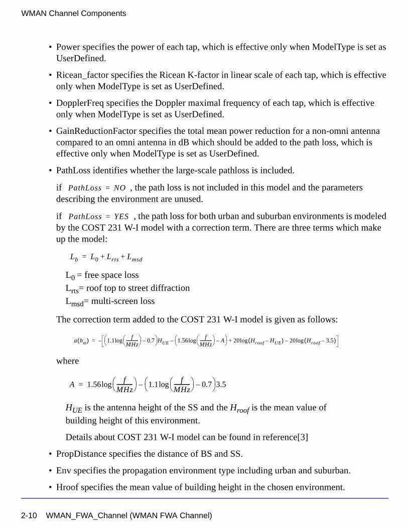
• Power specifies the power of each tap, which is effective only when ModelType is set as UserDefined.
• Ricean_factor specifies the Ricean K-factor in linear scale of each tap, which is effective only when ModelType is set as UserDefined.
• DopplerFreq specifies the Doppler maximal frequency of each tap, which is effective only when ModelType is set as UserDefined.
• GainReductionFactor specifies the total mean power reduction for a non-omni antenna compared to an omni antenna in dB which should be added to the path loss, which is effective only when ModelType is set as UserDefined.
• PathLoss identifies whether the large-scale pathloss is included.
if , the path loss is not included in this model and the parameters describing the environment are unused.
if , the path loss for both urban and suburban environments is modeled by the COST 231 W-I model with a correction term. There are three terms which make up the model:
L0 = free space loss
Lrts= roof top to street diffraction
Lmsd= multi-screen loss
The correction term added to the COST 231 W-I model is given as follows:
where
HUE is the antenna height of the SS and the Hroof is the mean value of
building height of this environment.
Details about COST 231 W-I model can be found in reference[3]
• PropDistance specifies the distance of BS and SS.
• Env specifies the propagation environment type including urban and suburban.
• Hroof specifies the mean value of building height in the chosen environment.
PathLoss NO=
PathLoss YES=
Lb L0 Lrts Lmsd+ +=
a hm( ) 1.1f
MHz------------ log 0.7–
HUE 1.56f
MHz------------ log A–
– 20 Hroof HUE–( )log 20 Hroof 3.5–( )log–+–=
A 1.56f
MHz------------ log 1.1
fMHz------------ log 0.7–
3.5–=
2-10 WMAN_FWA_Channel (WMAN FWA Channel)
• BldgSpace specifies the mean value of building spacing in the chosen environment.
• StreetWidth specifies the mean value of widths of street in the chosen environment.
• StreetOrient specifies the orientation of the road with respect to the Tx-Rx line.
• AntHeigh_UE and AntHeigh_BS specify the antenna height of the SS and BS.
PropDistance, Env, Hroof, BldgSpace, StreetWidth, StreetOrient, AntHeigh_UE, AntHeigh_BS are used to calculate the path loss when the PathLoss is ON.
4. Output delay
A delay of 64 tokens is introduced in this model.
References
[1] IEEE Std 802.16-2004, Part 16: Air Interface for Fixed Broadband Wireless Access Systems, Section 8.3 WirelessMAN-OFDM PHY, October 1, 2004.
[2] IEEE P802.16-2004/Cor1/D3, Corrigendum to IEEE Standard for Local and Metropolitan Area Networks - Part 16: Air Interface for Fixed Broadband Wireless Access Systems, May 2005.
[3] IEEE 802.16a-03/01, Channel Models for Fixed Wireless Applications, June 27, 2003.
WMAN_FWA_Channel (WMAN FWA Channel) 2-11
WMAN Channel Components
2-12 WMAN_FWA_Channel (WMAN FWA Channel)
Chapter 3: WMAN Channel Coding ComponentsThe channel coding models provide channel coding and scrambling in the transmitter end, and channel decoding in the receiving end.
• WMAN_CRC_Coder: CRC generator
• WMAN_Puncturer: puncturer or de-puncturer
• WMAN_RSDecoder: Reed Solomon decoder
• WMAN_Scramber: Scrambler
• WMAN_FEC: Forward error correction encoder
• WMAN_FEC_Decoder: Forward error correction decoder
3-1
WMAN Channel Coding Components
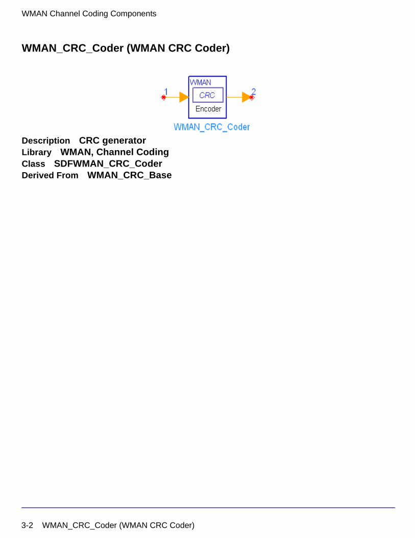
WMAN_CRC_Coder (WMAN CRC Coder)
Description CRC generatorLibrary WMAN, Channel CodingClass SDFWMAN_CRC_CoderDerived From WMAN_CRC_Base
3-2 WMAN_CRC_Coder (WMAN CRC Coder)
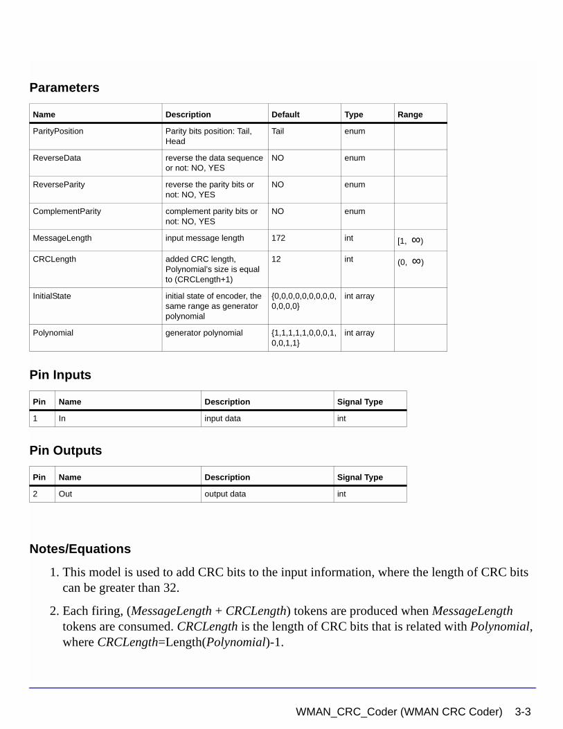
Parameters
Pin Inputs
Pin Outputs
Notes/Equations
1. This model is used to add CRC bits to the input information, where the length of CRC bits can be greater than 32.
2. Each firing, (MessageLength + CRCLength) tokens are produced when MessageLength tokens are consumed. CRCLength is the length of CRC bits that is related with Polynomial, where CRCLength=Length(Polynomial)-1.
Name Description Default Type Range
ParityPosition Parity bits position: Tail, Head
Tail enum
ReverseData reverse the data sequence or not: NO, YES
NO enum
ReverseParity reverse the parity bits or not: NO, YES
NO enum
ComplementParity complement parity bits or not: NO, YES
NO enum
MessageLength input message length 172 int [1, ∞)
CRCLength added CRC length, Polynomial’s size is equal to (CRCLength+1)
12 int (0, ∞)
InitialState initial state of encoder, the same range as generator polynomial
{0,0,0,0,0,0,0,0,0,0,0,0,0}
int array
Polynomial generator polynomial {1,1,1,1,1,0,0,0,1,0,0,1,1}
int array
Pin Name Description Signal Type
1 In input data int
Pin Name Description Signal Type
2 Out output data int
WMAN_CRC_Coder (WMAN CRC Coder) 3-3
WMAN Channel Coding Components
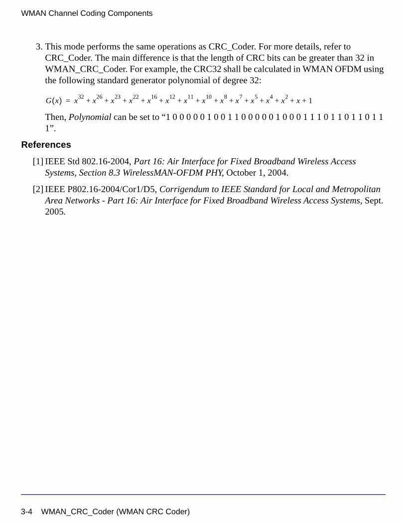
3. This mode performs the same operations as CRC_Coder. For more details, refer to CRC_Coder. The main difference is that the length of CRC bits can be greater than 32 in WMAN_CRC_Coder. For example, the CRC32 shall be calculated in WMAN OFDM using the following standard generator polynomial of degree 32:
Then, Polynomial can be set to “1 0 0 0 0 0 1 0 0 1 1 0 0 0 0 0 1 0 0 0 1 1 1 0 1 1 0 1 1 0 1 1 1”.
References
[1] IEEE Std 802.16-2004, Part 16: Air Interface for Fixed Broadband Wireless Access Systems, Section 8.3 WirelessMAN-OFDM PHY, October 1, 2004.
[2] IEEE P802.16-2004/Cor1/D5, Corrigendum to IEEE Standard for Local and Metropolitan Area Networks - Part 16: Air Interface for Fixed Broadband Wireless Access Systems, Sept. 2005.
G x( ) x32
x26
x23
x22
x16
x12
x11
x10
x8
x7
x5
x4
x2
x 1+ + + + + + + + + + + + + +=
3-4 WMAN_CRC_Coder (WMAN CRC Coder)
WMAN_FEC (WMAN Forward Error Correction Coder)
Description Forward error correction encoderLibrary WMAN, Channel CodingClass SDFWMAN_FEC
Parameters
Pin Inputs
Pin Outputs
Notes/Equations
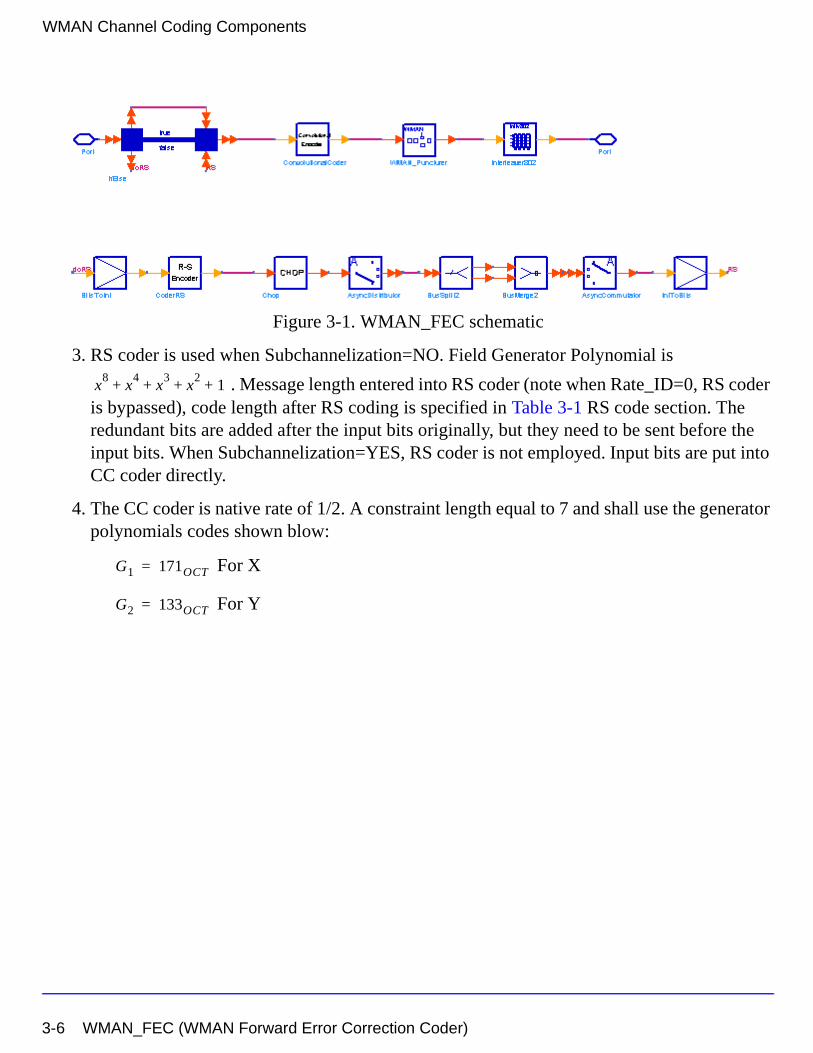
1. This subnetwork is used to do forward error correction coding, consisting of Reed-Solomon coder, Convolutional coder, puncturer and interleaver.
2. The schematic of this subnetwork is shown in Figure 3-1.
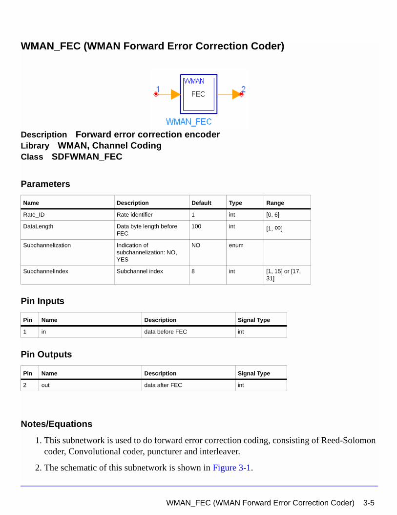
Name Description Default Type Range
Rate_ID Rate identifier 1 int [0, 6]
DataLength Data byte length before FEC
100 int [1, ∞]
Subchannelization Indication of subchannelization: NO, YES
NO enum
SubchannelIndex Subchannel index 8 int [1, 15] or [17, 31]
Pin Name Description Signal Type
1 in data before FEC int
Pin Name Description Signal Type
2 out data after FEC int
WMAN_FEC (WMAN Forward Error Correction Coder) 3-5
WMAN Channel Coding Components
Figure 3-1. WMAN_FEC schematic
3. RS coder is used when Subchannelization=NO. Field Generator Polynomial is
. Message length entered into RS coder (note when Rate_ID=0, RS coder is bypassed), code length after RS coding is specified in Table 3-1 RS code section. The redundant bits are added after the input bits originally, but they need to be sent before the input bits. When Subchannelization=YES, RS coder is not employed. Input bits are put into CC coder directly.
4. The CC coder is native rate of 1/2. A constraint length equal to 7 and shall use the generator polynomials codes shown blow:
For X
For Y
x8
x4
x3
x2
1+ + + +
G1 171OCT=
G2 133OCT=
3-6 WMAN_FEC (WMAN Forward Error Correction Coder)
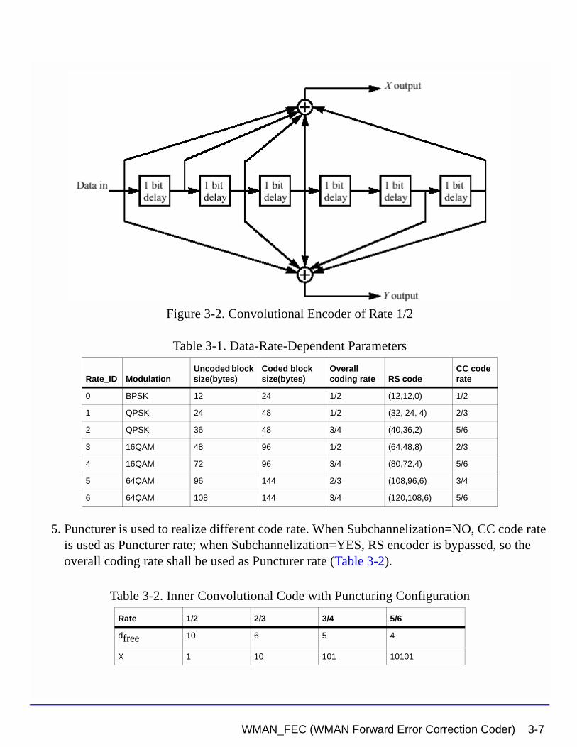
Figure 3-2. Convolutional Encoder of Rate 1/2
5. Puncturer is used to realize different code rate. When Subchannelization=NO, CC code rate is used as Puncturer rate; when Subchannelization=YES, RS encoder is bypassed, so the overall coding rate shall be used as Puncturer rate (Table 3-2).
Table 3-1. Data-Rate-Dependent Parameters
Rate_ID ModulationUncoded block size(bytes)
Coded block size(bytes)
Overall coding rate RS code
CC code rate
0 BPSK 12 24 1/2 (12,12,0) 1/2
1 QPSK 24 48 1/2 (32, 24, 4) 2/3
2 QPSK 36 48 3/4 (40,36,2) 5/6
3 16QAM 48 96 1/2 (64,48,8) 2/3
4 16QAM 72 96 3/4 (80,72,4) 5/6
5 64QAM 96 144 2/3 (108,96,6) 3/4
6 64QAM 108 144 3/4 (120,108,6) 5/6
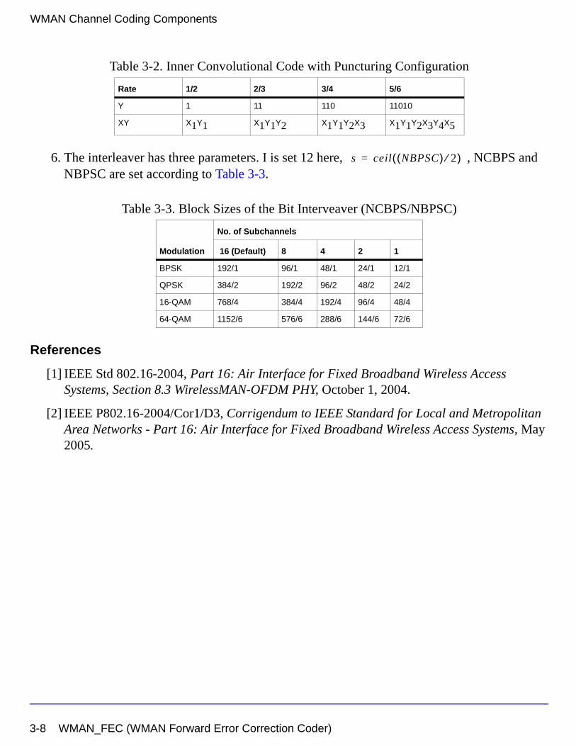
Table 3-2. Inner Convolutional Code with Puncturing Configuration
Rate 1/2 2/3 3/4 5/6
dfree 10 6 5 4
X 1 10 101 10101
WMAN_FEC (WMAN Forward Error Correction Coder) 3-7
WMAN Channel Coding Components
6. The interleaver has three parameters. I is set 12 here, , NCBPS and NBPSC are set according to Table 3-3.
References
[1] IEEE Std 802.16-2004, Part 16: Air Interface for Fixed Broadband Wireless Access Systems, Section 8.3 WirelessMAN-OFDM PHY, October 1, 2004.
[2] IEEE P802.16-2004/Cor1/D3, Corrigendum to IEEE Standard for Local and Metropolitan Area Networks - Part 16: Air Interface for Fixed Broadband Wireless Access Systems, May 2005.
Y 1 11 110 11010
XY X1Y1 X1Y1Y2 X1Y1Y2X3 X1Y1Y2X3Y4X5
Table 3-3. Block Sizes of the Bit Interveaver (NCBPS/NBPSC)
Modulation
No. of Subchannels
16 (Default) 8 4 2 1
BPSK 192/1 96/1 48/1 24/1 12/1
QPSK 384/2 192/2 96/2 48/2 24/2
16-QAM 768/4 384/4 192/4 96/4 48/4
64-QAM 1152/6 576/6 288/6 144/6 72/6
Table 3-2. Inner Convolutional Code with Puncturing Configuration
Rate 1/2 2/3 3/4 5/6
s ceil NBPSC( ) 2⁄( )=
3-8 WMAN_FEC (WMAN Forward Error Correction Coder)
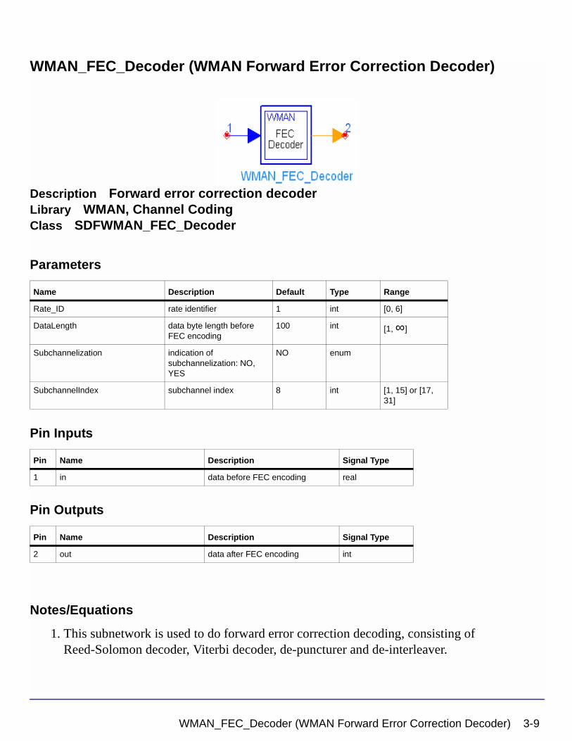
WMAN_FEC_Decoder (WMAN Forward Error Correction Decoder)
Description Forward error correction decoderLibrary WMAN, Channel CodingClass SDFWMAN_FEC_Decoder
Parameters
Pin Inputs
Pin Outputs
Notes/Equations
1. This subnetwork is used to do forward error correction decoding, consisting of Reed-Solomon decoder, Viterbi decoder, de-puncturer and de-interleaver.
Name Description Default Type Range
Rate_ID rate identifier 1 int [0, 6]
DataLength data byte length before FEC encoding
100 int [1, ∞]
Subchannelization indication of subchannelization: NO, YES
NO enum
SubchannelIndex subchannel index 8 int [1, 15] or [17, 31]
Pin Name Description Signal Type
1 in data before FEC encoding real
Pin Name Description Signal Type
2 out data after FEC encoding int
WMAN_FEC_Decoder (WMAN Forward Error Correction Decoder) 3-9
WMAN Channel Coding Components
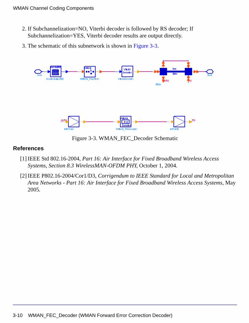
2. If Subchannelization=NO, Viterbi decoder is followed by RS decoder; If Subchannelization=YES, Viterbi decoder results are output directly.
3. The schematic of this subnetwork is shown in Figure 3-3..
Figure 3-3. WMAN_FEC_Decoder Schematic
References
[1] IEEE Std 802.16-2004, Part 16: Air Interface for Fixed Broadband Wireless Access Systems, Section 8.3 WirelessMAN-OFDM PHY, October 1, 2004.
[2] IEEE P802.16-2004/Cor1/D3, Corrigendum to IEEE Standard for Local and Metropolitan Area Networks - Part 16: Air Interface for Fixed Broadband Wireless Access Systems, May 2005.
3-10 WMAN_FEC_Decoder (WMAN Forward Error Correction Decoder)
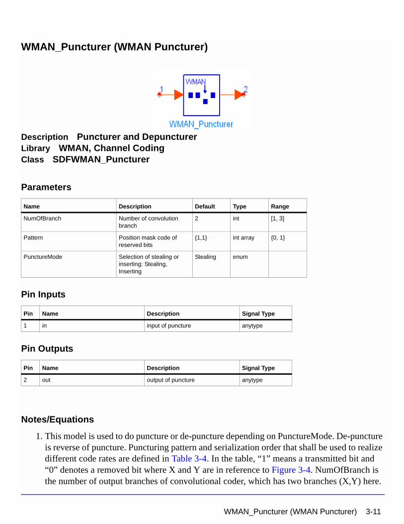
WMAN_Puncturer (WMAN Puncturer)
Description Puncturer and DepuncturerLibrary WMAN, Channel CodingClass SDFWMAN_Puncturer
Parameters
Pin Inputs
Pin Outputs
Notes/Equations
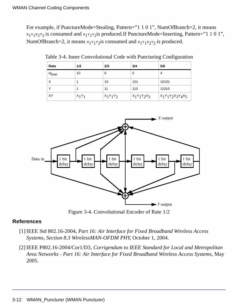
1. This model is used to do puncture or de-puncture depending on PunctureMode. De-puncture is reverse of puncture. Puncturing pattern and serialization order that shall be used to realize different code rates are defined in Table 3-4. In the table, “1” means a transmitted bit and “0” denotes a removed bit where X and Y are in reference to Figure 3-4. NumOfBranch is the number of output branches of convolutional coder, which has two branches (X,Y) here.
Name Description Default Type Range
NumOfBranch Number of convolution branch
2 int [1, 3]
Pattern Position mask code of reserved bits
{1,1} int array {0, 1}
PunctureMode Selection of stealing or inserting: Stealing, Inserting
Stealing enum
Pin Name Description Signal Type
1 in input of puncture anytype
Pin Name Description Signal Type
2 out output of puncture anytype
WMAN_Puncturer (WMAN Puncturer) 3-11
WMAN Channel Coding Components
For example, if PunctureMode=Stealing, Pattern=”1 1 0 1”, NumOfBranch=2, it means X1Y1X2Y2 is consumed and X1Y1Y2is produced.If PunctureMode=Inserting, Pattern=”1 1 0 1”,
NumOfBranch=2, it means X1Y1Y2is consumed and X1Y1X2Y2 is produced.
Figure 3-4. Convolutional Encoder of Rate 1/2
References
[1] IEEE Std 802.16-2004, Part 16: Air Interface for Fixed Broadband Wireless Access Systems, Section 8.3 WirelessMAN-OFDM PHY, October 1, 2004.
[2] IEEE P802.16-2004/Cor1/D3, Corrigendum to IEEE Standard for Local and Metropolitan Area Networks - Part 16: Air Interface for Fixed Broadband Wireless Access Systems, May 2005.
Table 3-4. Inner Convolutional Code with Puncturing Configuration
Rate 1/2 2/3 3/4 5/6
dfree 10 6 5 4
X 1 10 101 10101
Y 1 11 110 11010
XY X1Y1 X1Y1Y2 X1Y1Y2X3 X1Y1Y2X3Y4X5
3-12 WMAN_Puncturer (WMAN Puncturer)
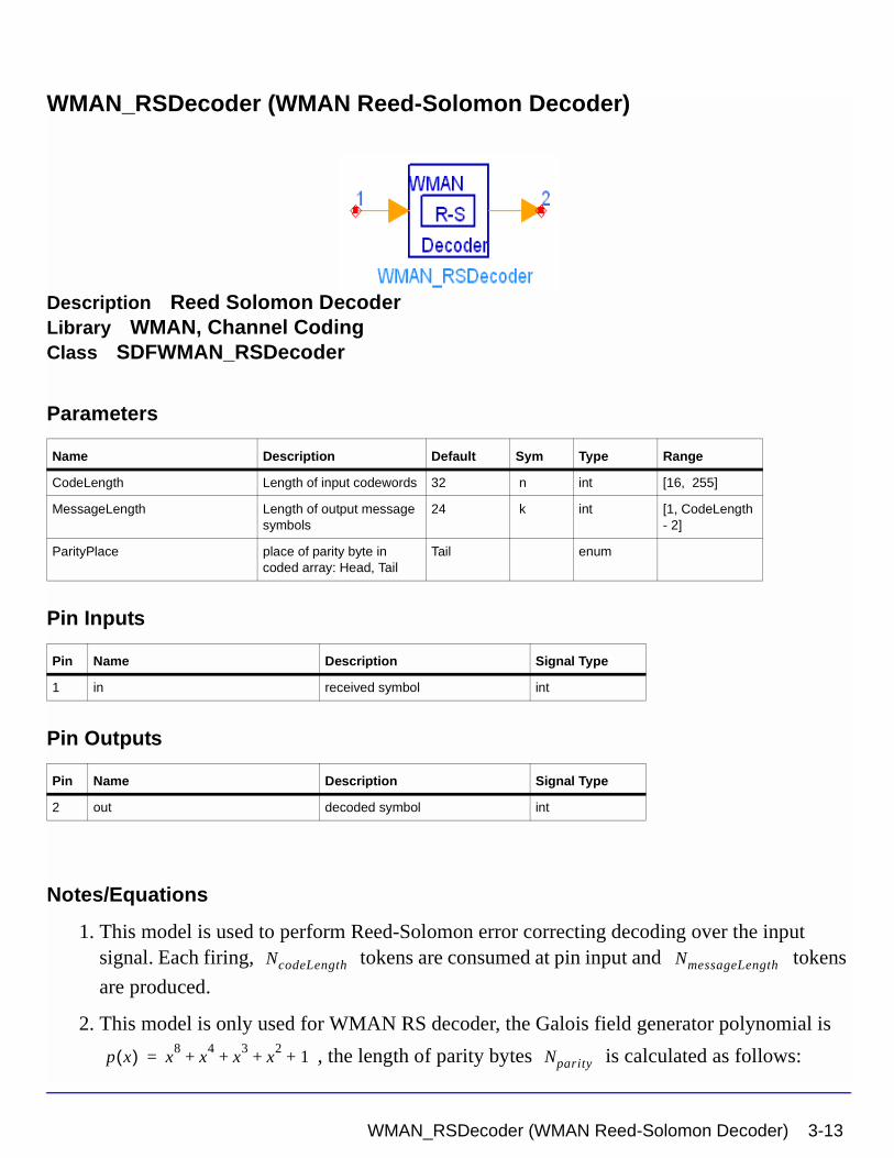
WMAN_RSDecoder (WMAN Reed-Solomon Decoder)
Description Reed Solomon DecoderLibrary WMAN, Channel CodingClass SDFWMAN_RSDecoder
Parameters
Pin Inputs
Pin Outputs
Notes/Equations
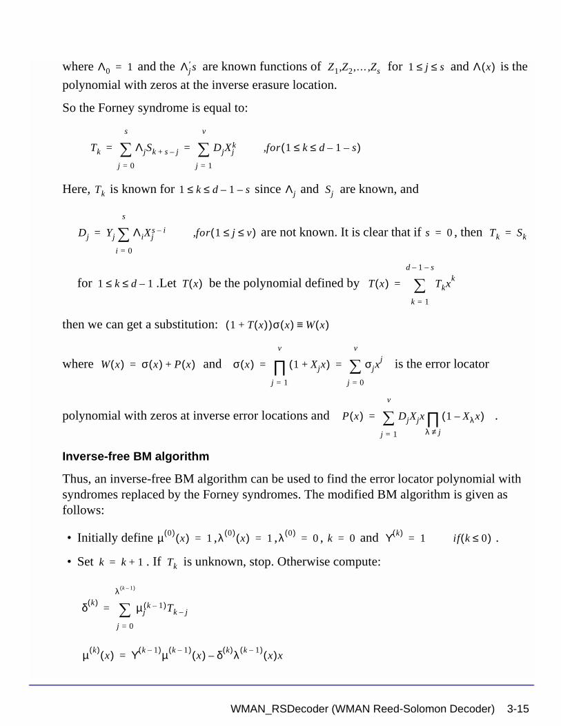
1. This model is used to perform Reed-Solomon error correcting decoding over the input signal. Each firing, tokens are consumed at pin input and tokens
are produced.
2. This model is only used for WMAN RS decoder, the Galois field generator polynomial is
, the length of parity bytes is calculated as follows:
Name Description Default Sym Type Range
CodeLength Length of input codewords 32 n int [16, 255]
MessageLength Length of output message symbols
24 k int [1, CodeLength - 2]
ParityPlace place of parity byte in coded array: Head, Tail
Tail enum
Pin Name Description Signal Type
1 in received symbol int
Pin Name Description Signal Type
2 out decoded symbol int
NcodeLength NmessageLength
p x( ) x8
x4
x3
x2
1+ + + += Nparity
WMAN_RSDecoder (WMAN Reed-Solomon Decoder) 3-13
WMAN Channel Coding Components
and the length of shortened bytes is calculated as follows:
The parity bytes can be placed as prefix or postfix of the information bytes for flexibility.
3. Decoding Routines
The Berlekamp iterative algorithm locates the error in RS code and generates an error location polynomial. By finding the root of the error location polynomial, the error position can be determined. If decoding is successful, the information symbols are output; otherwise, the received data is unaltered.
For the shortened code, the same number of “0” symbols is inserted into the same position as in the RS encoder, and a inverse-free Berlekamp-Massey Reed-Solomon decoder is used to decode the block. After decoding, the padded symbols are discarded leaving the desired information symbols.Forney defines an errata locator polynomial using what are now called the Forney syndromes to correct both errors and erasures of RS codes.
Getting Syndromes
Syndromes indicate an erroneous situation. When the generator polynomial g(x) and the received code word r(x) are given, the occurrence of one or more errors during transmission of an encoded block is known.Suppose that errors and erasures occur in the received
vector with .Let be a primitive element in GF( ),then the syndromes are:
where is the ith erasure location, is the ith erasure amplitude, is the ith error
location, and i is the ith error amplitude. is known for .So the syndrome
polynomial is:
Let the erasure locator polynomial be defined by
Nparity NcodeLength NmessageLength–=
Nshortened
Nshortened 16 Nparity–=
υ s
r s 2v+ d 1–≤ α 2m
Sk riαik
i 0=
n 1–
∑ WiZik
i 1=
s
∑ YiXik
i 1=
v
∑+= = 1 k d 1–≤ ≤( );
Zi Wi Xi
Sk 1 k d 1–≤ ≤
S x( ) Sjxj 1–
j 1=
d 1–
∑=
Λ x( ) 1 Zjx–( )j 1=
s
∏ Λjxj
j 0=
s
∑= =
3-14 WMAN_RSDecoder (WMAN Reed-Solomon Decoder)
where and the are known functions of for and is the
polynomial with zeros at the inverse erasure location.
So the Forney syndrome is equal to:
Here, is known for since and are known, and
are not known. It is clear that if , then
for .Let be the polynomial defined by
then we can get a substitution:
where and is the error locator
polynomial with zeros at inverse error locations and .
Inverse-free BM algorithm
Thus, an inverse-free BM algorithm can be used to find the error locator polynomial with syndromes replaced by the Forney syndromes. The modified BM algorithm is given as follows:
• Initially define , , , and .
• Set . If is unknown, stop. Otherwise compute:
Λ0 1= Λj′ s Z1 Z2 … Zs,,, 1 j s≤ ≤ Λ x( )
Tk ΛjSk s j–+
j 0=
s
∑ DjXjk
j 1=
v
∑= = for 1 k d 1– s–≤ ≤( ),
Tk 1 k d 1– s–≤ ≤ Λj Sj
Dj Yj ΛiXjs i–
i 0=
s
∑= for 1 j v≤ ≤( ), s 0= Tk Sk=
1 k d 1–≤ ≤ T x( ) T x( ) Tkxk
k 1=
d 1– s–
∑=
1 T x( )+( )σ x( ) W x( )≡
W x( ) σ x( ) P x( )+= σ x( ) 1 Xjx+( )j 1=
v
∏ σjxj
j 0=
v
∑= =
P x( ) DjXjx 1 Xλx–( )λ j≠∏
j 1=
v
∑=
µ 0( )x( ) 1= λ 0( )
x( ) 1= λ 0( )0= k 0= ϒ k( )
1= if k 0≤( )
k k 1+= Tk
δ k( ) µjk 1–( )Tk j–
j 0=
λ k 1–( )
∑=
µ k( )x( ) ϒ k 1–( )µ k 1–( )
x( ) δ k( )λ k 1–( )x( )x–=
WMAN_RSDecoder (WMAN Reed-Solomon Decoder) 3-15
WMAN Channel Coding Components
• return to step 2
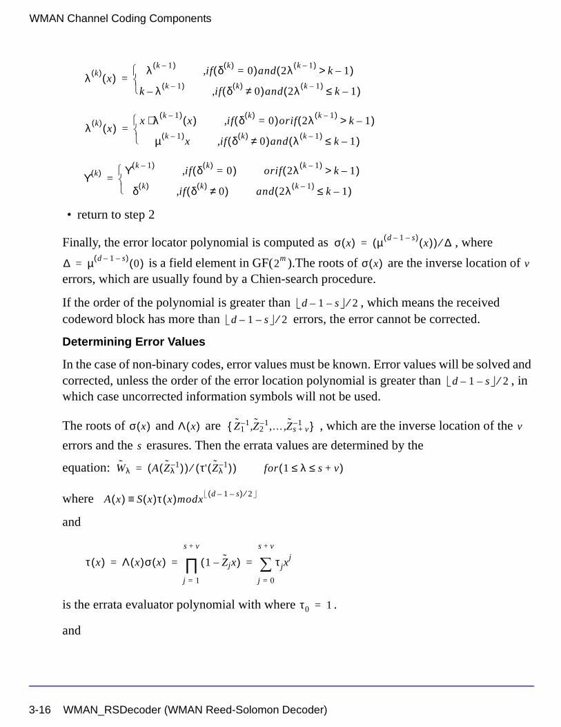
Finally, the error locator polynomial is computed as , where
is a field element in GF( ).The roots of are the inverse location of errors, which are usually found by a Chien-search procedure.
If the order of the polynomial is greater than , which means the received codeword block has more than errors, the error cannot be corrected.
Determining Error Values
In the case of non-binary codes, error values must be known. Error values will be solved and corrected, unless the order of the error location polynomial is greater than , in which case uncorrected information symbols will not be used.
The roots of and are , which are the inverse location of the
errors and the erasures. Then the errata values are determined by the
equation:
where
and
is the errata evaluator polynomial with where .
and
λ k( )x( )
λ k 1–( )if δ k( )
0=( )and 2λ k 1–( )k 1–>( ),
k λ–k 1–( )
if δ k( )0≠( )and 2λ k 1–( )
k 1–≤( ),
=
λ k( )x( )
x λ k 1–( )x( )⋅ if δ k( )
0=( )orif 2λ k 1–( )k 1–>( ),
µ k 1–( )x if δ k( )
0≠( )and λ k 1–( )k 1–≤( ),
=
ϒ k( ) ϒ k 1–( )if δ k( )
0=( ), orif 2λ k 1–( )k 1–>( )
δ k( )if δ k( )
0≠( ), and 2λ k 1–( )k 1–≤( )
=
σ x( ) µ d 1– s–( )x( )( ) ∆⁄=
∆ µ d 1– s–( )0( )= 2
m σ x( ) v
d 1– s– 2⁄d 1– s– 2⁄
d 1– s– 2⁄
σ x( ) Λ x( ) Z11– Z2
1– …, Zs v+1–,,{ } v
s
Wλ A Zλ1–( )( ) τ' Zλ
1–( )( )⁄= for 1 λ s v+≤ ≤( )
A x( ) S x( )τ x( )modxd 1– s–( ) 2⁄≡
τ x( ) Λ x( )σ x( ) 1 Zjx–( )j 1=
s v+
∏ τ jxj
j 0=
s v+
∑= = =
τ0 1=
3-16 WMAN_RSDecoder (WMAN Reed-Solomon Decoder)

is the derivative of with respect to x and evaluated at .
References
[1] IEEE Std 802.16-2004, Part 16: Air Interface for Fixed Broadband Wireless Access Systems, Section 8.3 WirelessMAN-OFDM PHY, October 1, 2004.
[2] IEEE P802.16-2004/Cor1/D3, Corrigendum to IEEE Standard for Local and Metropolitan Area Networks - Part 16: Air Interface for Fixed Broadband Wireless Access Systems, May 2005.
[3] Trieu-Kien Truong, J.H.Heng, King-Chu Hung, Inversionless Decoding of Both Errors and Erasures of Reed-Solomon Code, IEEE Trans. on communications, vol.46, No.8, pp973-pp976, August 1998.
[4] I.S.Reed, M.T.Shih, T.K.Truong, VLSI design of inverse-free Berlekamp-Massey algorithm, IEE Proceedings-E, vol138, No.5, pp295-pp298, September 1991.
τ′ Zλ1–( ) Zλ 1 ZjZλ
1––( )j λ≠∏=
τ x( ) x Zλ1–=
WMAN_RSDecoder (WMAN Reed-Solomon Decoder) 3-17
WMAN Channel Coding Components
WMAN_Scrambler (WMAN Scrambler)
Description ScramblerLibrary WMAN, Channel CodingClass SDFWMAN_Scrambler
3-18 WMAN_Scrambler (WMAN Scrambler)
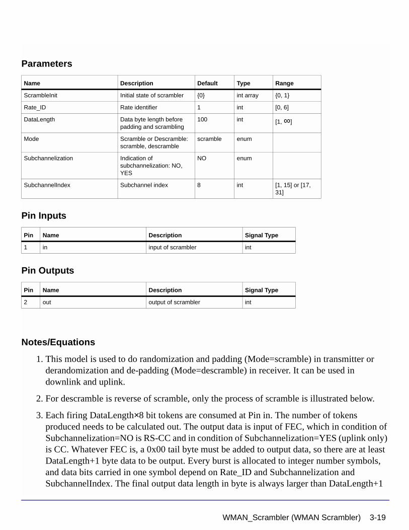
Parameters
Pin Inputs
Pin Outputs
Notes/Equations
1. This model is used to do randomization and padding (Mode=scramble) in transmitter or derandomization and de-padding (Mode=descramble) in receiver. It can be used in downlink and uplink.
2. For descramble is reverse of scramble, only the process of scramble is illustrated below.
3. Each firing DataLength×8 bit tokens are consumed at Pin in. The number of tokens produced needs to be calculated out. The output data is input of FEC, which in condition of Subchannelization=NO is RS-CC and in condition of Subchannelization=YES (uplink only) is CC. Whatever FEC is, a 0x00 tail byte must be added to output data, so there are at least DataLength+1 byte data to be output. Every burst is allocated to integer number symbols, and data bits carried in one symbol depend on Rate_ID and Subchannelization and SubchannelIndex. The final output data length in byte is always larger than DataLength+1
Name Description Default Type Range
ScrambleInit Initial state of scrambler {0} int array {0, 1}
Rate_ID Rate identifier 1 int [0, 6]
DataLength Data byte length before padding and scrambling
100 int [1, ∞]
Mode Scramble or Descramble: scramble, descramble
scramble enum
Subchannelization Indication of subchannelization: NO, YES
NO enum
SubchannelIndex Subchannel index 8 int [1, 15] or [17, 31]
Pin Name Description Signal Type
1 in input of scrambler int
Pin Name Description Signal Type
2 out output of scrambler int
WMAN_Scrambler (WMAN Scrambler) 3-19
WMAN Channel Coding Components
and sometimes is not integer multiple of length in byte (in condition of Subchannelization=YES). This means some integer bytes and bits need to be padded into the DataLength+1 byte data. Integer bytes are padded with 0xFF and bits are padded with bit0. The sequence of output is DataLength+0xFF+one byte tail 0x00+bit0... The DataLength data and padded 0xFF will be randomized.
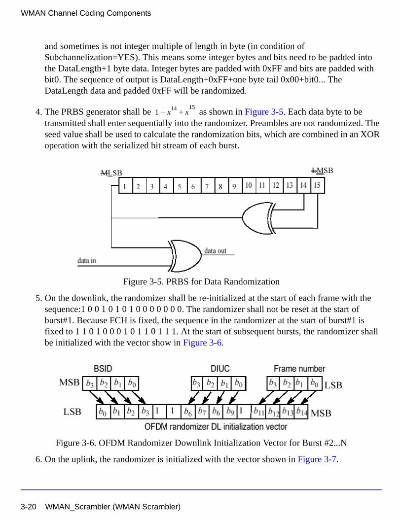
4. The PRBS generator shall be as shown in Figure 3-5. Each data byte to be transmitted shall enter sequentially into the randomizer. Preambles are not randomized. The seed value shall be used to calculate the randomization bits, which are combined in an XOR operation with the serialized bit stream of each burst.
Figure 3-5. PRBS for Data Randomization
5. On the downlink, the randomizer shall be re-initialized at the start of each frame with the sequence:1 0 0 1 0 1 0 1 0 0 0 0 0 0 0. The randomizer shall not be reset at the start of burst#1. Because FCH is fixed, the sequence in the randomizer at the start of burst#1 is fixed to 1 1 0 1 0 0 0 1 0 1 1 0 1 1 1. At the start of subsequent bursts, the randomizer shall be initialized with the vector show in Figure 3-6.
Figure 3-6. OFDM Randomizer Downlink Initialization Vector for Burst #2...N
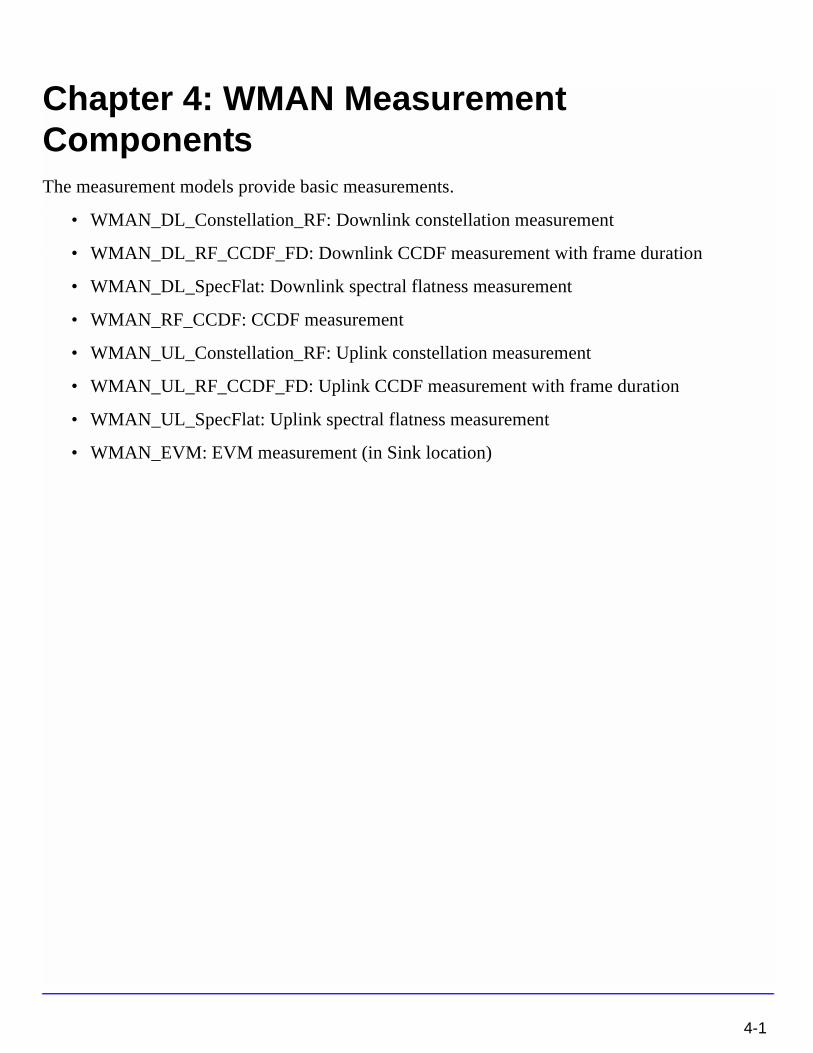
6. On the uplink, the randomizer is initialized with the vector shown in Figure 3-7.
1 x14
x+15
+
3-20 WMAN_Scrambler (WMAN Scrambler)
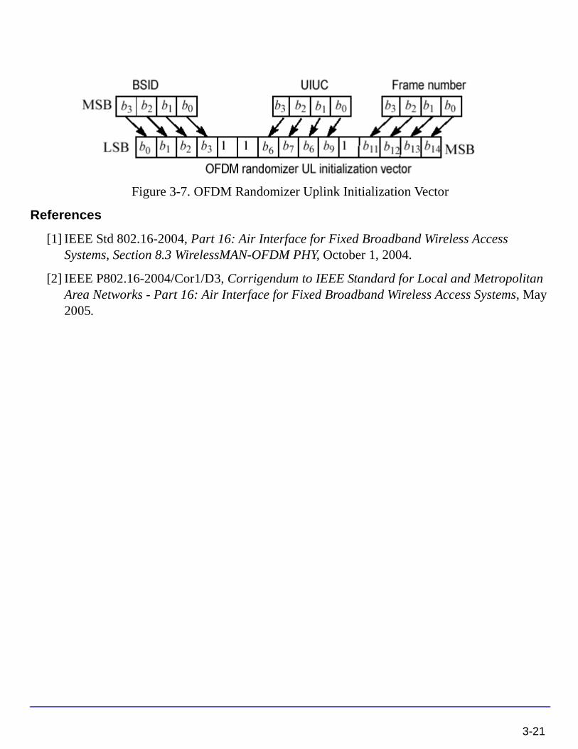
Figure 3-7. OFDM Randomizer Uplink Initialization Vector
References
[1] IEEE Std 802.16-2004, Part 16: Air Interface for Fixed Broadband Wireless Access Systems, Section 8.3 WirelessMAN-OFDM PHY, October 1, 2004.
[2] IEEE P802.16-2004/Cor1/D3, Corrigendum to IEEE Standard for Local and Metropolitan Area Networks - Part 16: Air Interface for Fixed Broadband Wireless Access Systems, May 2005.
3-21

WMAN Channel Coding Components
3-22
Chapter 4: WMAN Measurement ComponentsThe measurement models provide basic measurements.
• WMAN_DL_Constellation_RF: Downlink constellation measurement
• WMAN_DL_RF_CCDF_FD: Downlink CCDF measurement with frame duration
• WMAN_DL_SpecFlat: Downlink spectral flatness measurement
• WMAN_RF_CCDF: CCDF measurement
• WMAN_UL_Constellation_RF: Uplink constellation measurement
• WMAN_UL_RF_CCDF_FD: Uplink CCDF measurement with frame duration
• WMAN_UL_SpecFlat: Uplink spectral flatness measurement
• WMAN_EVM: EVM measurement (in Sink location)
4-1
WMAN Measurement Components
WMAN_DL_Constellation_RF (WMAN Downlink Constellation Measurement)
Description Downlink constellaton measurement with broadcast message and frame durationLibrary WMAN, MeasurementClass TSDFWMAN_DL_Constellation_RF
4-2 WMAN_DL_Constellation_RF (WMAN Downlink Constellation Measurement)
Parameters
Name Description Default Unit Type Range
RIn Input resistance 50 Ohm Ohm int (0, ∞)
RTemp TEMPERATURE - 273.15 Celsius real [- 273.15, ∞]
FCarrier Carrier frequency 1900 MHz Hz real (0, ∞)
Sensitivity voltage output sensitivity, Vout/Vin
1 real (-∞, ∞)
Phase Reference phase in degrees
0.0 deg real (-∞, ∞)
GainImbalance Gain imbalance in dB Q channel relative to I channel
0.0 real (-∞, ∞)
PhaseImbalance Phase imbalance in dB Q channel relative to I channel
0.0 real (-∞, ∞)
NumberOfBurst Number of Burst 1 int [1, 16]
DataLength MAC PDU payload byte length of each burst
{100} int array [1, 4095]
Rate_ID Rate ID of each burst {1} int array [0, 6]
PreamblePresent Preamble present or not {0} int array {0, 1}
PrmlTimeShift Preamble time shift of each burst
{0} int array [0, 255]
OversamplingOption Oversampling ratio option: Ratio 1, Ratio 2, Ratio 4, Ratio 8, Ratio 16, Ratio 32
Ratio 1 enum
Bandwidth Bandwidth 1.75 MHz Hz real (0, 1e9]
CyclicPrefix Cyclic prefix 0.25 real [0, 1]
IdleInterval Idle interval 10.0 usec sec real [0, 1000)
PilotPN_Phase Pilot PN phase 0 int [0, 4095]
start Frame Number 1200 int [0, ∞)
stop Frame Number 2399 int [start, ∞)
FrameMode Frame mode: FDD, TDD FDD enum
DL_Ratio Downlink ratio 0.5 real [0.01, 0.99]
FrameDuration Frame duration: Continuous, time 2.5 ms, time 4 ms, time 5 ms, time 8 ms, time 10 ms, time 12.5 ms, time 20 ms
Continuous enum
Brd_Message Broadcast message enabled or not: NO, YES
NO enum
WMAN_DL_Constellation_RF (WMAN Downlink Constellation Measurement) 4-3
WMAN Measurement Components
Pin Inputs
Notes/Equations
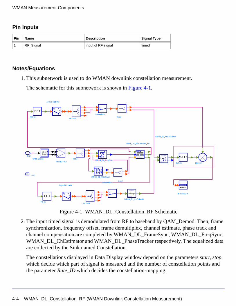
1. This subnetwork is used to do WMAN downlink constellation measurement.
The schematic for this subnetwork is shown in Figure 4-1.
Figure 4-1. WMAN_DL_Constellation_RF Schematic
2. The input timed signal is demodulated from RF to baseband by QAM_Demod. Then, frame synchronization, frequency offset, frame demultiplex, channel estimate, phase track and channel compensation are completed by WMAN_DL_FrameSync, WMAN_DL_FreqSync, WMAN_DL_ChEstimator and WMAN_DL_PhaseTracker respectively. The equalized data are collected by the Sink named Constellation.
The constellations displayed in Data Display window depend on the parameters start, stop which decide which part of signal is measured and the number of constellation points and the parameter Rate_ID which decides the constellation-mapping.
Pin Name Description Signal Type
1 RF_Signal input of RF signal timed
4-4 WMAN_DL_Constellation_RF (WMAN Downlink Constellation Measurement)

References
[1] IEEE Std 802.16-2004, Part 16: Air Interface for Fixed Broadband Wireless Access Systems, Section 8.3 WirelessMAN-OFDM PHY, October 1, 2004.
[2] IEEE P802.16-2004/Cor1/D3, Corrigendum to IEEE Standard for Local and Metropolitan Area Networks - Part 16: Air Interface for Fixed Broadband Wireless Access Systems, May 2005.
WMAN_DL_Constellation_RF (WMAN Downlink Constellation Measurement) 4-5
WMAN Measurement Components
WMAN_DL_RF_CCDF_FD (WMAN Downlink RF CCDF FD)
Description Downlink CCDF measurment with broadcast message and frame durationLibrary WMAN, MeasurementClass TSDFWMAN_DL_RF_CCDF_FD
4-6 WMAN_DL_RF_CCDF_FD (WMAN Downlink RF CCDF FD)
Parameters
Pin Inputs
Notes/Equations
Name Description Default Unit Type Range
RLoad Source resistance 50 Ohm Ohm int (0, ∞)
RTemp TEMPERATURE - 273.15 Celsius real [- 273.15, ∞]
StartSample Sample from which measurement begin
0 int
SymLen length of input signal symbol
2560 int
SymNum Number of symbols 1 int
OutputPoint Indicate output precision 100 int
RefR Reference resistance 50 Ohm Ohm real
NumberOfBurst Number of Burst 1 int [1, 16]
DataLength MAC PDU payload byte length of each burst
{100} int array [1, 16383]
Rate_ID Rate ID of each burst {1} int array [0, 6]
PreamblePresent Preamble present {0} int array {0, 1}
IdleInterval Idle interval 10 usec sec real [0, 1000]
Bandwidth Bandwidth 1.75 MHz Hz real (0, 1e9]
OversamplingOption Oversampling ratio option: Ratio 1, Ratio 2, Ratio 4, Ratio 8, Ratio 16, Ratio 32
Ratio 1 enum
CyclicPrefix Cyclic prefix 0.25 real [0, 1]
FrameMode Frame mode: FDD, TDD FDD enum
DL_Ratio Downlink ratio 0.5 real [0.01, 0.99]
FrameDuration Frame duration: Continuous, time 2.5 ms, time 4 ms, time 5 ms, time 8 ms, time 10 ms, time 12.5 ms, time 20 ms
time 5 ms enum
Brd_Message Broadcast message enabled or not: NO, YES
NO enum
Pin Name Description Signal Type
1 RF_Signal received RF signal to be measured timed
WMAN_DL_RF_CCDF_FD (WMAN Downlink RF CCDF FD) 4-7
WMAN Measurement Components
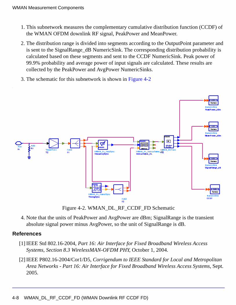
1. This subnetwork measures the complementary cumulative distribution function (CCDF) of the WMAN OFDM downlink RF signal, PeakPower and MeanPower.
2. The distribution range is divided into segments according to the OutputPoint parameter and is sent to the SignalRange_dB NumericSink. The corresponding distribution probability is calculated based on these segments and sent to the CCDF NumericSink. Peak power of 99.9% probability and average power of input signals are calculated. These results are collected by the PeakPower and AvgPower NumericSinks.
3. The schematic for this subnetwork is shown in Figure 4-2.
Figure 4-2. WMAN_DL_RF_CCDF_FD Schematic
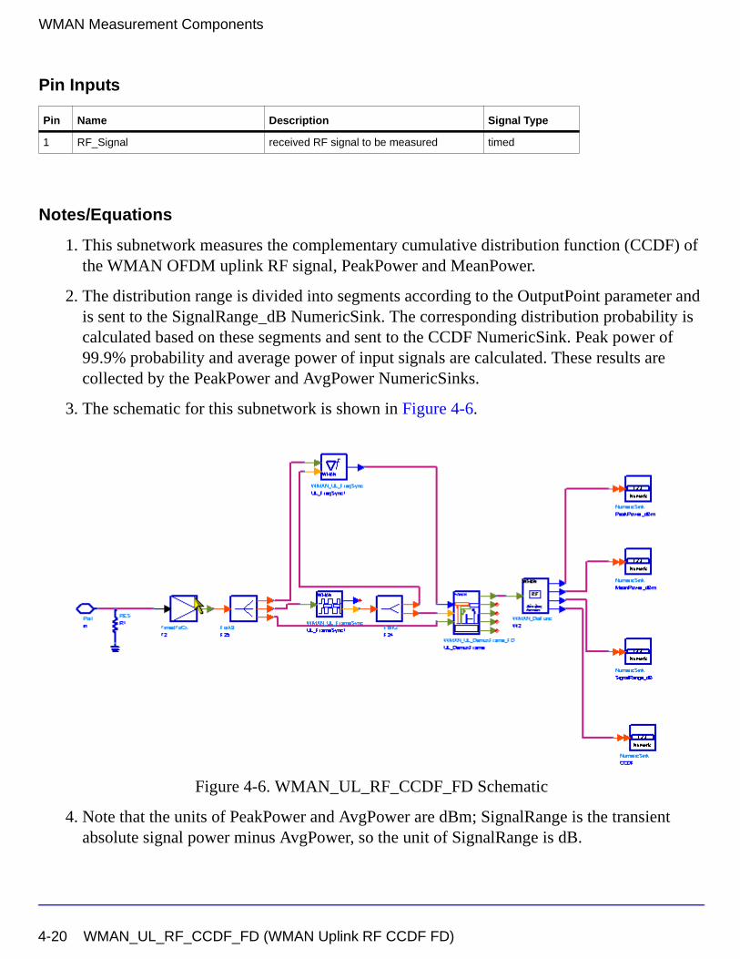
4. Note that the units of PeakPower and AvgPower are dBm; SignalRange is the transient absolute signal power minus AvgPower, so the unit of SignalRange is dB.
References
[1] IEEE Std 802.16-2004, Part 16: Air Interface for Fixed Broadband Wireless Access Systems, Section 8.3 WirelessMAN-OFDM PHY, October 1, 2004.
[2] IEEE P802.16-2004/Cor1/D5, Corrigendum to IEEE Standard for Local and Metropolitan Area Networks - Part 16: Air Interface for Fixed Broadband Wireless Access Systems, Sept. 2005.
4-8 WMAN_DL_RF_CCDF_FD (WMAN Downlink RF CCDF FD)
WMAN_DL_SpecFlat (WMAN Downlink Spectral Flatness Measurement)
Description Downlink spectral flatness measurementLibrary WMAN, MeasurementClass TSDFWMAN_DL_SpecFlat
WMAN_DL_SpecFlat (WMAN Downlink Spectral Flatness Measurement) 4-9
WMAN Measurement Components
Parameters
Pin Inputs
Notes/Equations
1. This subnetwork is used to measure the spectral flatness of WMAN OFDM Downlink
Name Description Default Unit Type Range
RIn Input resistance 50 Ohm Ohm int (0, ∞)
RTemp TEMPERATURE - 273.15 Celsius real [- 273.15, ∞]
FCarrier Carrier frequency 3407 MHz Hz real (0, ∞)
OversamplingOption Oversampling ratio option: Ratio 1, Ratio 2, Ratio 4, Ratio 8, Ratio 16, Ratio 32
Ratio 1 enum
Bandwidth Bandwidth 1.75 MHz Hz real (0, 1e9]
CyclicPrefix Cyclic prefix 0.25 real [0, 1]
FrameMode Frame mode: FDD, TDD FDD enum
DL_Ratio Downlink ratio 0.5 real [0.01, 0.99]
FrameDuration Frame duration: Continuous, time 2.5 ms, time 4 ms, time 5 ms, time 8 ms, time 10 ms, time 12.5 ms, time 20 ms
Continuous enum
Brd_Message Broadcast message enabled or not: NO, YES
NO enum
IdleInterval Idle interval 0.0 usec sec real [0, 1000)
NumberOfBurst Number of Burst 1 int [1, 16]
DataLength MAC PDU payload byte length of each burst
{100} int array [1, 4095]
Rate_ID Rate ID of each burst {1} int array [0, 6]
PreamblePresent Preamble present or not {0} int array {0, 1}
PrmlTimeShift Preamble time shift of each burst
{0} int array [0, 255]
FramesToAverage Number of frames for the average CIR
1 int [1, ∞)
Pin Name Description Signal Type
1 RF_Signal input of RF signal timed
4-10 WMAN_DL_SpecFlat (WMAN Downlink Spectral Flatness Measurement)
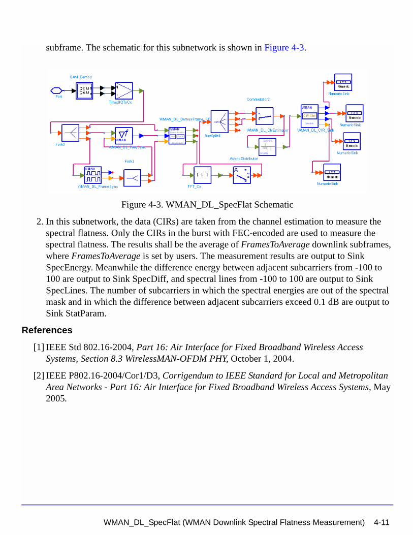
subframe. The schematic for this subnetwork is shown in Figure 4-3.
Figure 4-3. WMAN_DL_SpecFlat Schematic
2. In this subnetwork, the data (CIRs) are taken from the channel estimation to measure the spectral flatness. Only the CIRs in the burst with FEC-encoded are used to measure the spectral flatness. The results shall be the average of FramesToAverage downlink subframes, where FramesToAverage is set by users. The measurement results are output to Sink SpecEnergy. Meanwhile the difference energy between adjacent subcarriers from -100 to 100 are output to Sink SpecDiff, and spectral lines from -100 to 100 are output to Sink SpecLines. The number of subcarriers in which the spectral energies are out of the spectral mask and in which the difference between adjacent subcarriers exceed 0.1 dB are output to Sink StatParam.
References
[1] IEEE Std 802.16-2004, Part 16: Air Interface for Fixed Broadband Wireless Access Systems, Section 8.3 WirelessMAN-OFDM PHY, October 1, 2004.
[2] IEEE P802.16-2004/Cor1/D3, Corrigendum to IEEE Standard for Local and Metropolitan Area Networks - Part 16: Air Interface for Fixed Broadband Wireless Access Systems, May 2005.
WMAN_DL_SpecFlat (WMAN Downlink Spectral Flatness Measurement) 4-11
WMAN Measurement Components
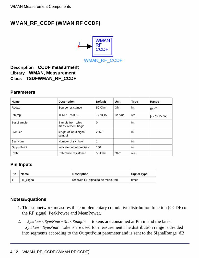
WMAN_RF_CCDF (WMAN RF CCDF)
Description CCDF measurmentLibrary WMAN, MeasurementClass TSDFWMAN_RF_CCDF
Parameters
Pin Inputs
Notes/Equations
1. This subnetwork measures the complementary cumulative distribution function (CCDF) of the RF signal, PeakPower and MeanPower.
2. tokens are consumed at Pin in and the latest tokens are used for measurement.The distribution range is divided
into segments according to the OutputPoint parameter and is sent to the SignalRange_dB
Name Description Default Unit Type Range
RLoad Source resistance 50 Ohm Ohm int (0, ∞)
RTemp TEMPERATURE - 273.15 Celsius real [- 273.15, ∞]
StartSample Sample from which measurement begin
0 int
SymLen length of input signal symbol
2560 int
SymNum Number of symbols 1 int
OutputPoint Indicate output precision 100 int
RefR Reference resistance 50 Ohm Ohm real
Pin Name Description Signal Type
1 RF_Signal received RF signal to be measured timed
SymLen SymNum St+× artSample
SymLen SymNum×
4-12 WMAN_RF_CCDF (WMAN RF CCDF)
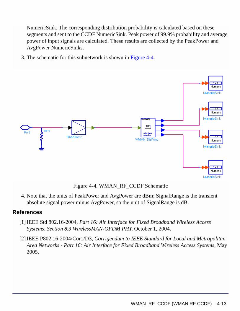
NumericSink. The corresponding distribution probability is calculated based on these segments and sent to the CCDF NumericSink. Peak power of 99.9% probability and average power of input signals are calculated. These results are collected by the PeakPower and AvgPower NumericSinks.
3. The schematic for this subnetwork is shown in Figure 4-4.
Figure 4-4. WMAN_RF_CCDF Schematic
4. Note that the units of PeakPower and AvgPower are dBm; SignalRange is the transient absolute signal power minus AvgPower, so the unit of SignalRange is dB.
References
[1] IEEE Std 802.16-2004, Part 16: Air Interface for Fixed Broadband Wireless Access Systems, Section 8.3 WirelessMAN-OFDM PHY, October 1, 2004.
[2] IEEE P802.16-2004/Cor1/D3, Corrigendum to IEEE Standard for Local and Metropolitan Area Networks - Part 16: Air Interface for Fixed Broadband Wireless Access Systems, May 2005.
WMAN_RF_CCDF (WMAN RF CCDF) 4-13
WMAN Measurement Components
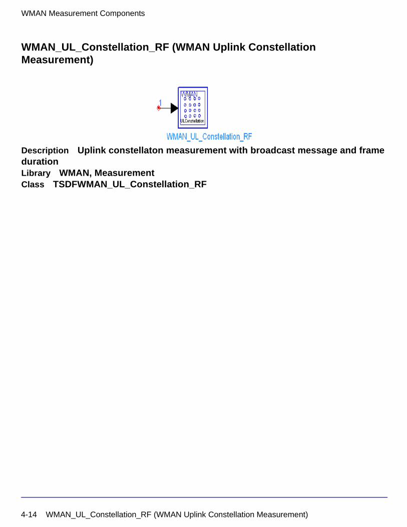
WMAN_UL_Constellation_RF (WMAN Uplink Constellation Measurement)
Description Uplink constellaton measurement with broadcast message and frame durationLibrary WMAN, MeasurementClass TSDFWMAN_UL_Constellation_RF
4-14 WMAN_UL_Constellation_RF (WMAN Uplink Constellation Measurement)
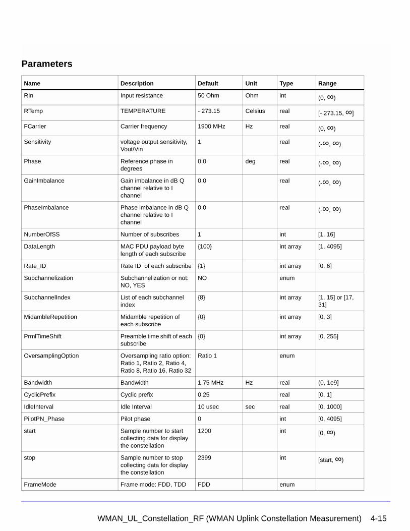
Parameters
Name Description Default Unit Type Range
RIn Input resistance 50 Ohm Ohm int (0, ∞)
RTemp TEMPERATURE - 273.15 Celsius real [- 273.15, ∞]
FCarrier Carrier frequency 1900 MHz Hz real (0, ∞)
Sensitivity voltage output sensitivity, Vout/Vin
1 real (-∞, ∞)
Phase Reference phase in degrees
0.0 deg real (-∞, ∞)
GainImbalance Gain imbalance in dB Q channel relative to I channel
0.0 real (-∞, ∞)
PhaseImbalance Phase imbalance in dB Q channel relative to I channel
0.0 real (-∞, ∞)
NumberOfSS Number of subscribes 1 int [1, 16]
DataLength MAC PDU payload byte length of each subscribe
{100} int array [1, 4095]
Rate_ID Rate ID of each subscribe {1} int array [0, 6]
Subchannelization Subchannelization or not: NO, YES
NO enum
SubchannelIndex List of each subchannel index
{8} int array [1, 15] or [17, 31]
MidambleRepetition Midamble repetition of each subscribe
{0} int array [0, 3]
PrmlTimeShift Preamble time shift of each subscribe
{0} int array [0, 255]
OversamplingOption Oversampling ratio option: Ratio 1, Ratio 2, Ratio 4, Ratio 8, Ratio 16, Ratio 32
Ratio 1 enum
Bandwidth Bandwidth 1.75 MHz Hz real (0, 1e9]
CyclicPrefix Cyclic prefix 0.25 real [0, 1]
IdleInterval Idle Interval 10 usec sec real [0, 1000]
PilotPN_Phase Pilot phase 0 int [0, 4095]
start Sample number to start collecting data for display the constellation
1200 int [0, ∞)
stop Sample number to stop collecting data for display the constellation
2399 int [start, ∞)
FrameMode Frame mode: FDD, TDD FDD enum
WMAN_UL_Constellation_RF (WMAN Uplink Constellation Measurement) 4-15
WMAN Measurement Components
Pin Inputs
Notes/Equations
1. This subnetwork is used to do WMAN uplink constellation measurement.
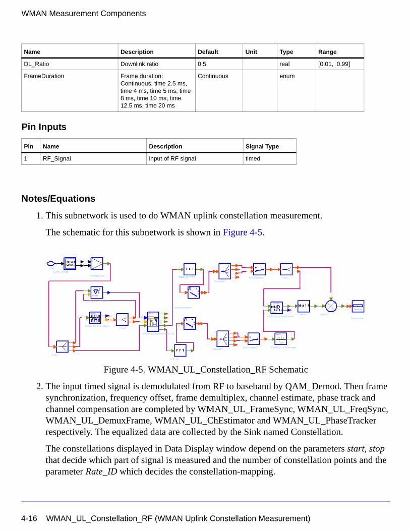
The schematic for this subnetwork is shown in Figure 4-5.
Figure 4-5. WMAN_UL_Constellation_RF Schematic
2. The input timed signal is demodulated from RF to baseband by QAM_Demod. Then frame synchronization, frequency offset, frame demultiplex, channel estimate, phase track and channel compensation are completed by WMAN_UL_FrameSync, WMAN_UL_FreqSync, WMAN_UL_DemuxFrame, WMAN_UL_ChEstimator and WMAN_UL_PhaseTracker respectively. The equalized data are collected by the Sink named Constellation.
The constellations displayed in Data Display window depend on the parameters start, stop that decide which part of signal is measured and the number of constellation points and the parameter Rate_ID which decides the constellation-mapping.
DL_Ratio Downlink ratio 0.5 real [0.01, 0.99]
FrameDuration Frame duration: Continuous, time 2.5 ms, time 4 ms, time 5 ms, time 8 ms, time 10 ms, time 12.5 ms, time 20 ms
Continuous enum
Pin Name Description Signal Type
1 RF_Signal input of RF signal timed
Name Description Default Unit Type Range
4-16 WMAN_UL_Constellation_RF (WMAN Uplink Constellation Measurement)
References
[1] IEEE Std 802.16-2004, Part 16: Air Interface for Fixed Broadband Wireless Access Systems, Section 8.3 WirelessMAN-OFDM PHY, October 1, 2004.
[2] IEEE P802.16-2004/Cor1/D3, Corrigendum to IEEE Standard for Local and Metropolitan Area Networks - Part 16: Air Interface for Fixed Broadband Wireless Access Systems, May 2005.
WMAN_UL_Constellation_RF (WMAN Uplink Constellation Measurement) 4-17
WMAN Measurement Components
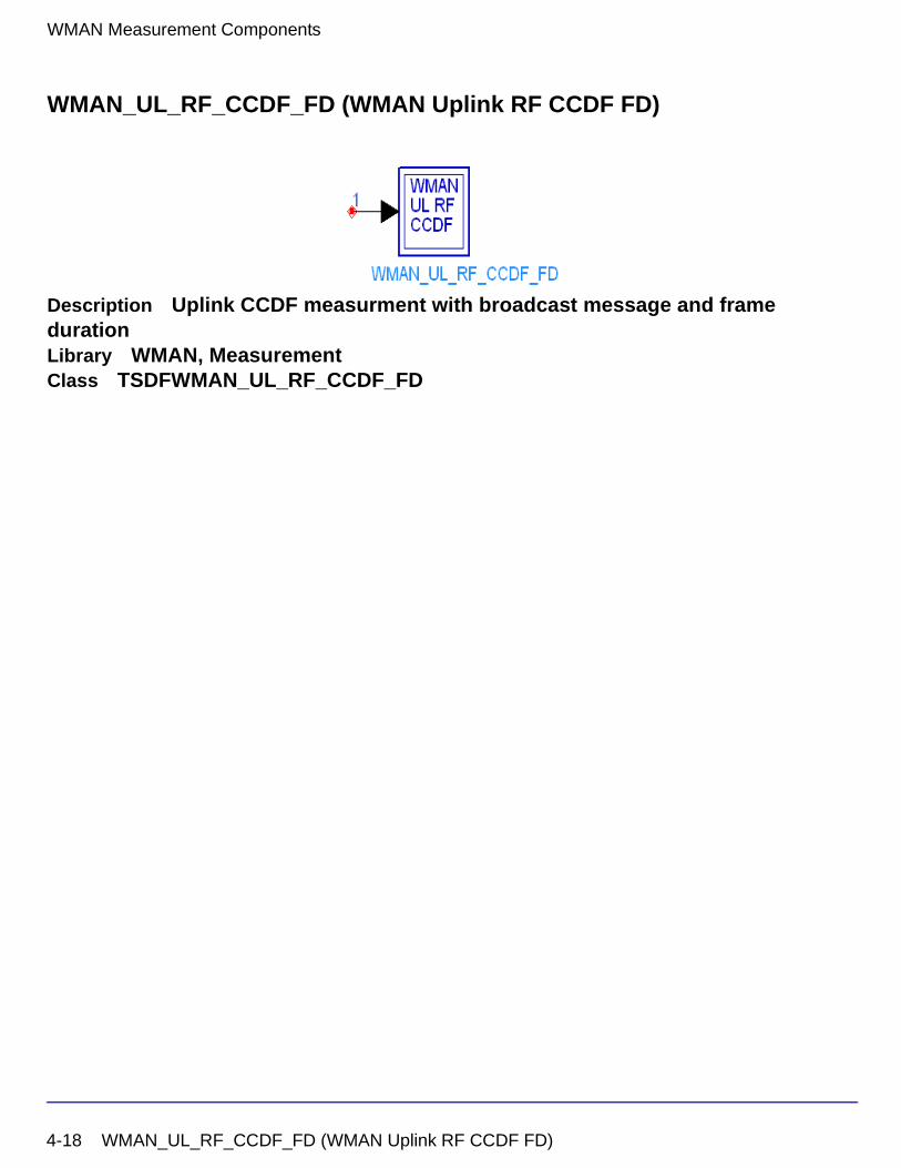
WMAN_UL_RF_CCDF_FD (WMAN Uplink RF CCDF FD)
Description Uplink CCDF measurment with broadcast message and frame durationLibrary WMAN, MeasurementClass TSDFWMAN_UL_RF_CCDF_FD
4-18 WMAN_UL_RF_CCDF_FD (WMAN Uplink RF CCDF FD)
Parameters
Name Description Default Unit Type Range
RLoad Source resistance 50 Ohm Ohm int (0, ∞)
RTemp TEMPERATURE - 273.15 Celsius real [- 273.15, ∞]
StartSample Sample from which measurement begin
0 int
SymLen length of input signal symbol
2560 int
SymNum Number of symbols 1 int
OutputPoint Indicate output precision 100 int
RefR Reference resistance 50 Ohm Ohm real
NumberOfSS Number of subscribers 1 int [1, 16]
DataLength MAC PDU payload byte length of each subscriber
{100} int array [1, 16383]
Rate_ID Rate ID of each subscriber {1} int array [0, 6]
Subchannelization Subchannelization or not: NO, YES
NO enum
SubchannelIndex List of each subchannel index
{8} int array [1, 15] or [17, 31]
MidambleRepetition Midamble repetition of each subscriber
{0} int array [0, 3]
IdleInterval Idle Interval 10 usec sec real [0, 1000]
Bandwidth Bandwidth 1.75 MHz Hz real (0, 1e9]
OversamplingOption Oversampling ratio option: Ratio 1, Ratio 2, Ratio 4, Ratio 8, Ratio 16, Ratio 32
Ratio 1 enum
CyclicPrefix Cyclic prefix 0.25 real [0, 1]
PrmlTimeShift Preamble time shift of each subscriber
{0} int array [0, 255]
FrameMode Frame mode: FDD, TDD FDD enum
DL_Ratio Downlink ratio 0.5 real [0.01, 0.99]
FrameDuration Frame duration: Continuous, time 2.5 ms, time 4 ms, time 5 ms, time 8 ms, time 10 ms, time 12.5 ms, time 20 ms
time 5 ms enum
WMAN_UL_RF_CCDF_FD (WMAN Uplink RF CCDF FD) 4-19
WMAN Measurement Components
Pin Inputs
Notes/Equations
1. This subnetwork measures the complementary cumulative distribution function (CCDF) of the WMAN OFDM uplink RF signal, PeakPower and MeanPower.
2. The distribution range is divided into segments according to the OutputPoint parameter and is sent to the SignalRange_dB NumericSink. The corresponding distribution probability is calculated based on these segments and sent to the CCDF NumericSink. Peak power of 99.9% probability and average power of input signals are calculated. These results are collected by the PeakPower and AvgPower NumericSinks.
3. The schematic for this subnetwork is shown in Figure 4-6.
Figure 4-6. WMAN_UL_RF_CCDF_FD Schematic
4. Note that the units of PeakPower and AvgPower are dBm; SignalRange is the transient absolute signal power minus AvgPower, so the unit of SignalRange is dB.
Pin Name Description Signal Type
1 RF_Signal received RF signal to be measured timed
4-20 WMAN_UL_RF_CCDF_FD (WMAN Uplink RF CCDF FD)
References
[1] IEEE Std 802.16-2004, Part 16: Air Interface for Fixed Broadband Wireless Access Systems, Section 8.3 WirelessMAN-OFDM PHY, October 1, 2004.
[2] IEEE P802.16-2004/Cor1/D5, Corrigendum to IEEE Standard for Local and Metropolitan Area Networks - Part 16: Air Interface for Fixed Broadband Wireless Access Systems, Sept. 2005.
WMAN_UL_RF_CCDF_FD (WMAN Uplink RF CCDF FD) 4-21
WMAN Measurement Components
WMAN_UL_SpecFlat (WMAN Uplink SpecFlat)
Description Uplink spectral flatness measurementLibrary WMAN, MeasurementClass TSDFWMAN_UL_SpecFlat
4-22 WMAN_UL_SpecFlat (WMAN Uplink SpecFlat)
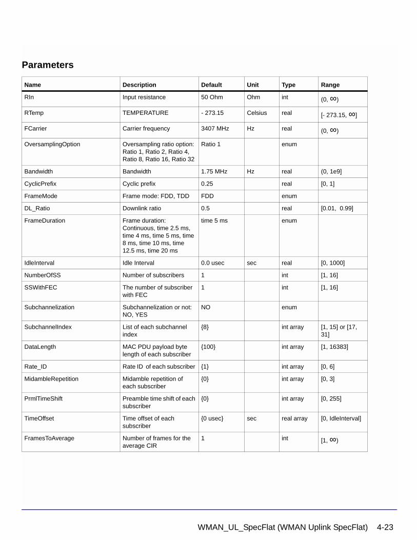
Parameters
Name Description Default Unit Type Range
RIn Input resistance 50 Ohm Ohm int (0, ∞)
RTemp TEMPERATURE - 273.15 Celsius real [- 273.15, ∞]
FCarrier Carrier frequency 3407 MHz Hz real (0, ∞)
OversamplingOption Oversampling ratio option: Ratio 1, Ratio 2, Ratio 4, Ratio 8, Ratio 16, Ratio 32
Ratio 1 enum
Bandwidth Bandwidth 1.75 MHz Hz real (0, 1e9]
CyclicPrefix Cyclic prefix 0.25 real [0, 1]
FrameMode Frame mode: FDD, TDD FDD enum
DL_Ratio Downlink ratio 0.5 real [0.01, 0.99]
FrameDuration Frame duration: Continuous, time 2.5 ms, time 4 ms, time 5 ms, time 8 ms, time 10 ms, time 12.5 ms, time 20 ms
time 5 ms enum
IdleInterval Idle Interval 0.0 usec sec real [0, 1000]
NumberOfSS Number of subscribers 1 int [1, 16]
SSWithFEC The number of subscriber with FEC
1 int [1, 16]
Subchannelization Subchannelization or not: NO, YES
NO enum
SubchannelIndex List of each subchannel index
{8} int array [1, 15] or [17, 31]
DataLength MAC PDU payload byte length of each subscriber
{100} int array [1, 16383]
Rate_ID Rate ID of each subscriber {1} int array [0, 6]
MidambleRepetition Midamble repetition of each subscriber
{0} int array [0, 3]
PrmlTimeShift Preamble time shift of each subscriber
{0} int array [0, 255]
TimeOffset Time offset of each subscriber
{0 usec} sec real array [0, IdleInterval]
FramesToAverage Number of frames for the average CIR
1 int [1, ∞)
WMAN_UL_SpecFlat (WMAN Uplink SpecFlat) 4-23
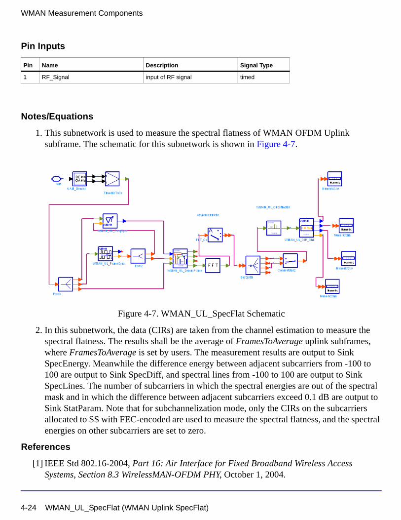
WMAN Measurement Components
Pin Inputs
Notes/Equations
1. This subnetwork is used to measure the spectral flatness of WMAN OFDM Uplink subframe. The schematic for this subnetwork is shown in Figure 4-7.
Figure 4-7. WMAN_UL_SpecFlat Schematic
2. In this subnetwork, the data (CIRs) are taken from the channel estimation to measure the spectral flatness. The results shall be the average of FramesToAverage uplink subframes, where FramesToAverage is set by users. The measurement results are output to Sink SpecEnergy. Meanwhile the difference energy between adjacent subcarriers from -100 to 100 are output to Sink SpecDiff, and spectral lines from -100 to 100 are output to Sink SpecLines. The number of subcarriers in which the spectral energies are out of the spectral mask and in which the difference between adjacent subcarriers exceed 0.1 dB are output to Sink StatParam. Note that for subchannelization mode, only the CIRs on the subcarriers allocated to SS with FEC-encoded are used to measure the spectral flatness, and the spectral energies on other subcarriers are set to zero.
References
[1] IEEE Std 802.16-2004, Part 16: Air Interface for Fixed Broadband Wireless Access Systems, Section 8.3 WirelessMAN-OFDM PHY, October 1, 2004.
Pin Name Description Signal Type
1 RF_Signal input of RF signal timed
4-24 WMAN_UL_SpecFlat (WMAN Uplink SpecFlat)
[2] IEEE P802.16-2004/Cor1/D3, Corrigendum to IEEE Standard for Local and Metropolitan Area Networks - Part 16: Air Interface for Fixed Broadband Wireless Access Systems, May 2005.
WMAN_UL_SpecFlat (WMAN Uplink SpecFlat) 4-25
WMAN Measurement Components
4-26 WMAN_UL_SpecFlat (WMAN Uplink SpecFlat)
Chapter 5: WMAN Multiplex ComponentsThe multiplex models provide framing and de-framing in WMAN transceivers.
• WMAN_BurstWoFEC: Other bursts generator without FEC
• WMAN_DL_DemuxBurst: Downlink bursts demultiplexer
• WMAN_DL_DemuxBurst_FD: Downlink bursts demultiplexer with frame duration
• WMAN_DL_MuxBurst: Downlink bursts multiplexer
• WMAN_DL_MuxBurst_FD: Downlink bursts multiplexer with frame duration
• WMAN_DL_MuxFrame: Downlink frame demultiplexer
• WMAN_DemuxOFDMSym: OFDM symbol demultiplexer
• WMAN_UL_DemuxBurst: Uplink bursts demultiplexer
• WMAN_UL_MuxBurst: Uplink bursts multiplexer
• WMAN_UL_MuxFrame: Uplink frame demultiplexer
• WMAN_UL_MuxOFDMSym: Uplink OFDM symbol multiplexer
5-1
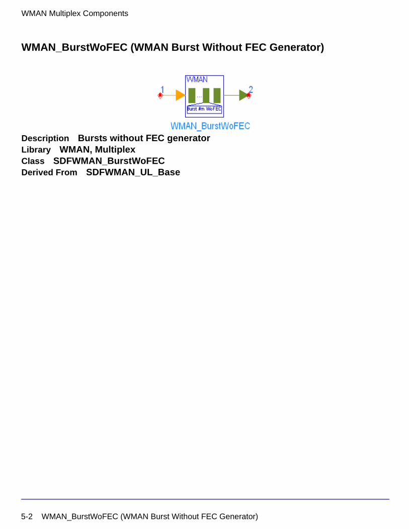
WMAN Multiplex Components
WMAN_BurstWoFEC (WMAN Burst Without FEC Generator)
Description Bursts without FEC generatorLibrary WMAN, MultiplexClass SDFWMAN_BurstWoFECDerived From SDFWMAN_UL_Base
5-2 WMAN_BurstWoFEC (WMAN Burst Without FEC Generator)
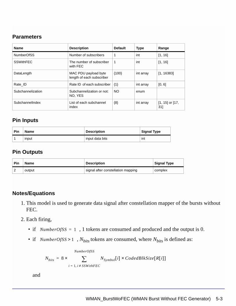
Parameters
Pin Inputs
Pin Outputs
Notes/Equations
1. This model is used to generate data signal after constellation mapper of the bursts without FEC.
2. Each firing,
• if , 1 tokens are consumed and produced and the output is 0.
• if , Nbits tokens are consumed, where Nbits is defined as:
and
Name Description Default Type Range
NumberOfSS Number of subscribers 1 int [1, 16]
SSWithFEC The number of subscriber with FEC
1 int [1, 16]
DataLength MAC PDU payload byte length of each subscriber
{100} int array [1, 16383]
Rate_ID Rate ID of each subscriber {1} int array [0, 6]
Subchannelization Subchannelization or not: NO, YES
NO enum
SubchannelIndex List of each subchannel index
{8} int array [1, 15] or [17, 31]
Pin Name Description Signal Type
1 input input data bits int
Pin Name Description Signal Type
2 output signal after constellation mapping complex
NumberOfSS 1=
NumberOfSS 1>
Nbits 8 NSymbol i[ ]i 1 i SSWithFEC≠,=
NumberOfSS
∑× CodedBlkSize R i[ ][ ]×=
WMAN_BurstWoFEC (WMAN Burst Without FEC Generator) 5-3
WMAN Multiplex Components
tokens are produced,
where, NSymbol[i] is the number of OFDM symbols of the ith SS and depends on
DataLength[i] and Rate_ID[i].
The data-rate-dependent parameters are defined in Table 5-1.
3. If this model is used in downlink, the parameters NumberOfSS and SSWithFEC mean the NumberOfBurst and BurstWithFEC respectively.
References
[1] IEEE Std 802.16-2004, Part 16: Air Interface for Fixed Broadband Wireless Access Systems, Section 8.3 WirelessMAN-OFDM PHY, October 1, 2004.
[2] IEEE P802.16-2004/Cor1/D3, Corrigendum to IEEE Standard for Local and Metropolitan Area Networks - Part 16: Air Interface for Fixed Broadband Wireless Access Systems, May 2005.
Table 5-1. Data-Rate-Dependent Parameters
Rate_ID (R) Modulation
Uncoded block size (bytes)
Coded block size (bytes)
Overall coding rate RS code CC code rate
0 BPSK 12 24 1/2 (12,12,0) 1/2
1 QPSK 24 48 1/2 (32,24,4) 2/3
2 QPSK 36 48 3/4 (40,36,2) 5/6
3 16-QAM 48 96 1/2 (64,48,8) 2/3
4 16-QAM 72 96 3/4 (80,72,4) 5/6
5 64-QAM 96 144 2/3 (108,96,6) 3/4
6 64-QAM 108 144 3/4 (120,108,6) 5/6
192 NSymbol i[ ]i 1 i SSWithFEC≠,=
NumberOfSS
∑×
5-4 WMAN_BurstWoFEC (WMAN Burst Without FEC Generator)
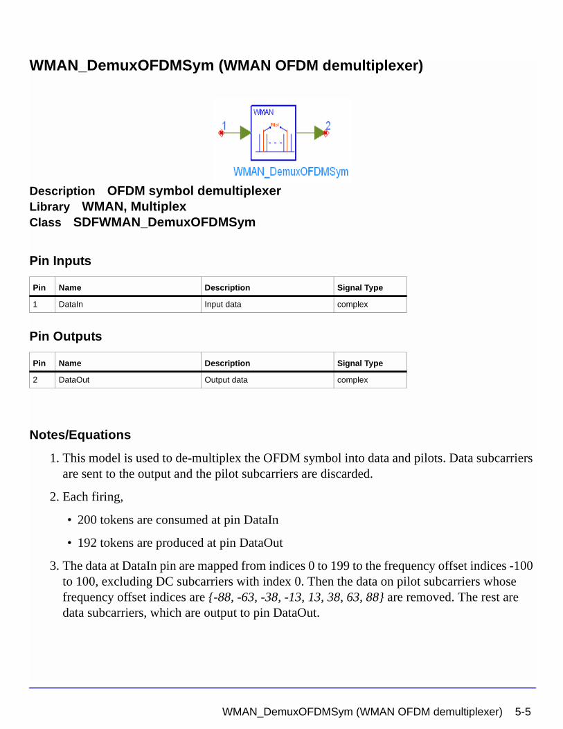
WMAN_DemuxOFDMSym (WMAN OFDM demultiplexer)
Description OFDM symbol demultiplexerLibrary WMAN, MultiplexClass SDFWMAN_DemuxOFDMSym
Pin Inputs
Pin Outputs
Notes/Equations
1. This model is used to de-multiplex the OFDM symbol into data and pilots. Data subcarriers are sent to the output and the pilot subcarriers are discarded.
2. Each firing,
• 200 tokens are consumed at pin DataIn
• 192 tokens are produced at pin DataOut
3. The data at DataIn pin are mapped from indices 0 to 199 to the frequency offset indices -100 to 100, excluding DC subcarriers with index 0. Then the data on pilot subcarriers whose frequency offset indices are {-88, -63, -38, -13, 13, 38, 63, 88} are removed. The rest are data subcarriers, which are output to pin DataOut.
Pin Name Description Signal Type
1 DataIn Input data complex
Pin Name Description Signal Type
2 DataOut Output data complex
WMAN_DemuxOFDMSym (WMAN OFDM demultiplexer) 5-5
WMAN Multiplex Components
References
[1] IEEE Std 802.16-2004, Part 16: Air Interface for Fixed Broadband Wireless Access Systems, Section 8.3 WirelessMAN-OFDM PHY, October 1, 2004.
[2] IEEE P802.16-2004/Cor1/D3, Corrigendum to IEEE Standard for Local and Metropolitan Area Networks - Part 16: Air Interface for Fixed Broadband Wireless Access Systems, May 2005.
5-6 WMAN_DemuxOFDMSym (WMAN OFDM demultiplexer)
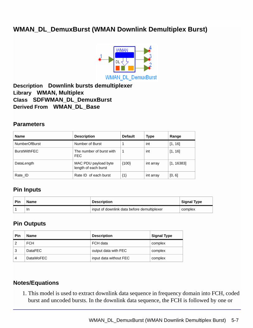
WMAN_DL_DemuxBurst (WMAN Downlink Demultiplex Burst)
Description Downlink bursts demultiplexerLibrary WMAN, MultiplexClass SDFWMAN_DL_DemuxBurstDerived From WMAN_DL_Base
Parameters
Pin Inputs
Pin Outputs
Notes/Equations
1. This model is used to extract downlink data sequence in frequency domain into FCH, coded burst and uncoded bursts. In the downlink data sequence, the FCH is followed by one or
Name Description Default Type Range
NumberOfBurst Number of Burst 1 int [1, 16]
BurstWithFEC The number of burst with FEC
1 int [1, 16]
DataLength MAC PDU payload byte length of each burst
{100} int array [1, 16383]
Rate_ID Rate ID of each burst {1} int array [0, 6]
Pin Name Description Signal Type
1 In input of downlink data before demultiplexer complex
Pin Name Description Signal Type
2 FCH FCH data complex
3 DataFEC output data with FEC complex
4 DataWoFEC input data without FEC complex
WMAN_DL_DemuxBurst (WMAN Downlink Demultiplex Burst) 5-7
WMAN Multiplex Components
multiple downlink bursts. The coded burst can occupy anywhere of downlink bursts. This is inverse function of WMAN_DL_MuxBurst.
2. Each firing,
tokens are consumed at pin In.
where is the number of OFDM symbols of ith downlink burst. 192 means the
number of data subcarriers in one OFDM symbol. Rate_ID (R) determine the number of data symbols per DL burst. Data-rate-dependent parameters (modulation, coding rate, coded bytes/uncoded bytes per OFDM symbol) are set according to Table 5-2, which is based on the specification.
The number of OFDM symbols of ith downlink burst ( ) is calculated as:
where
• The FCH burst is one OFDM symbol long, so 192 tokens are produced at pin FCH.
• tokens are produced at pin DataWithFEC.
• tokens are produced at pin DataWoFEC.
Table 5-2. Data-Rate-Dependent Parameters
Rate_ID(R) Modulation
Uncoded block size(bytes)
Coded block size(bytes)
Overall coding rate RS code CC code rate
0 BPSK 12 24 1/2 (12,12,0) 1/2
1 QPSK 24 48 1/2 (32,24,4) 2/3
2 QPSK 36 48 3/4 (40,36,2) 5/6
3 16-QAM 48 96 1/2 (64,48,8) 2/3
4 16-QAM 72 96 3/4 (80,72,4) 5/6
5 64-QAM 96 144 2/3 (108,96,6) 3/4
6 64-QAM 108 144 3/4 (120,108,6) 5/6
192 1 NSymbol i[ ]i 1=
NumberOfBurst
∑+
×
NSymbol i[ ]
NSymbol i[ ]
NSymbol i[ ] ceil DataLength i[ ] 11+( ) uncodedBlockSize R i[ ][ ]( )⁄( )=
192 N× Symbol butstWithFEC[ ]
192 NSymbol i[ ]i 1 i burstWithFEC≠,=
NumberOfBurst
∑
×
5-8 WMAN_DL_DemuxBurst (WMAN Downlink Demultiplex Burst)

References
[1] IEEE Std 802.16-2004, Part 16: Air Interface for Fixed Broadband Wireless Access Systems, Section 8.3 WirelessMAN-OFDM PHY, October 1, 2004.
[2] IEEE P802.16-2004/Cor1/D3, Corrigendum to IEEE Standard for Local and Metropolitan Area Networks - Part 16: Air Interface for Fixed Broadband Wireless Access Systems, May 2005.
WMAN_DL_DemuxBurst (WMAN Downlink Demultiplex Burst) 5-9
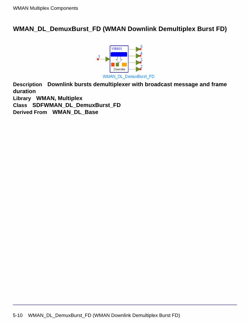
WMAN Multiplex Components
WMAN_DL_DemuxBurst_FD (WMAN Downlink Demultiplex Burst FD)
Description Downlink bursts demultiplexer with broadcast message and frame durationLibrary WMAN, MultiplexClass SDFWMAN_DL_DemuxBurst_FDDerived From WMAN_DL_Base
5-10 WMAN_DL_DemuxBurst_FD (WMAN Downlink Demultiplex Burst FD)
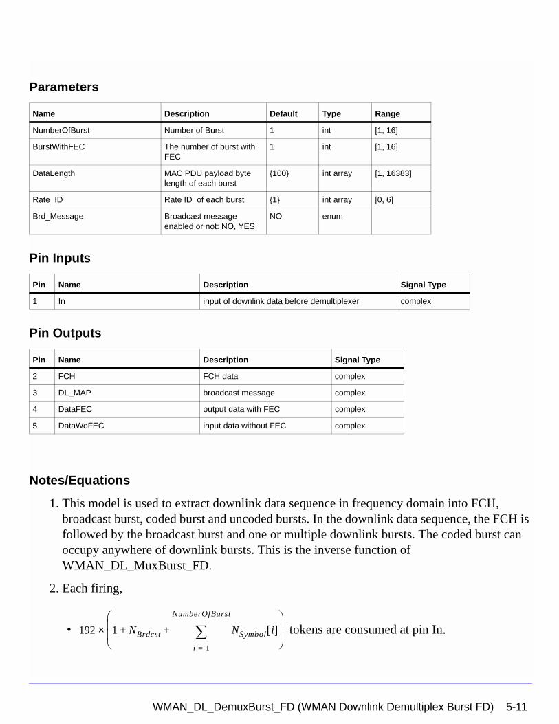
Parameters
Pin Inputs
Pin Outputs
Notes/Equations
1. This model is used to extract downlink data sequence in frequency domain into FCH, broadcast burst, coded burst and uncoded bursts. In the downlink data sequence, the FCH is followed by the broadcast burst and one or multiple downlink bursts. The coded burst can occupy anywhere of downlink bursts. This is the inverse function of WMAN_DL_MuxBurst_FD.
2. Each firing,
• tokens are consumed at pin In.
Name Description Default Type Range
NumberOfBurst Number of Burst 1 int [1, 16]
BurstWithFEC The number of burst with FEC
1 int [1, 16]
DataLength MAC PDU payload byte length of each burst
{100} int array [1, 16383]
Rate_ID Rate ID of each burst {1} int array [0, 6]
Brd_Message Broadcast message enabled or not: NO, YES
NO enum
Pin Name Description Signal Type
1 In input of downlink data before demultiplexer complex
Pin Name Description Signal Type
2 FCH FCH data complex
3 DL_MAP broadcast message complex
4 DataFEC output data with FEC complex
5 DataWoFEC input data without FEC complex
192 1 NBrdcst NSymbol i[ ]i 1=
NumberOfBurst
∑+ +
×
WMAN_DL_DemuxBurst_FD (WMAN Downlink Demultiplex Burst FD) 5-11
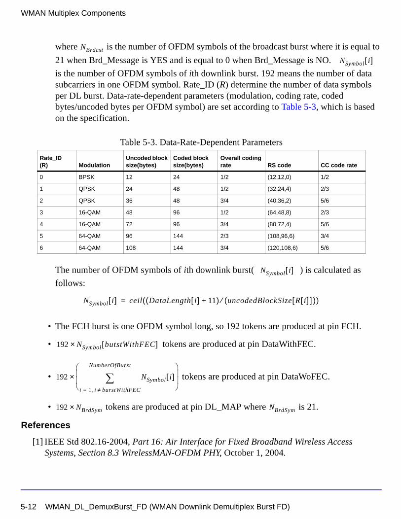
WMAN Multiplex Components
where is the number of OFDM symbols of the broadcast burst where it is equal to
21 when Brd_Message is YES and is equal to 0 when Brd_Message is NO.
is the number of OFDM symbols of ith downlink burst. 192 means the number of data subcarriers in one OFDM symbol. Rate_ID (R) determine the number of data symbols per DL burst. Data-rate-dependent parameters (modulation, coding rate, coded bytes/uncoded bytes per OFDM symbol) are set according to Table 5-3, which is based on the specification.
The number of OFDM symbols of ith downlink burst( ) is calculated as
follows:
• The FCH burst is one OFDM symbol long, so 192 tokens are produced at pin FCH.
• tokens are produced at pin DataWithFEC.
• tokens are produced at pin DataWoFEC.
• tokens are produced at pin DL_MAP where is 21.
References
[1] IEEE Std 802.16-2004, Part 16: Air Interface for Fixed Broadband Wireless Access Systems, Section 8.3 WirelessMAN-OFDM PHY, October 1, 2004.
Table 5-3. Data-Rate-Dependent Parameters
Rate_ID(R) Modulation
Uncoded block size(bytes)
Coded block size(bytes)
Overall coding rate RS code CC code rate
0 BPSK 12 24 1/2 (12,12,0) 1/2
1 QPSK 24 48 1/2 (32,24,4) 2/3
2 QPSK 36 48 3/4 (40,36,2) 5/6
3 16-QAM 48 96 1/2 (64,48,8) 2/3
4 16-QAM 72 96 3/4 (80,72,4) 5/6
5 64-QAM 96 144 2/3 (108,96,6) 3/4
6 64-QAM 108 144 3/4 (120,108,6) 5/6
NBrdcst
NSymbol i[ ]
NSymbol i[ ]
NSymbol i[ ] ceil DataLength i[ ] 11+( ) uncodedBlockSize R i[ ][ ]( )⁄( )=
192 N× Symbol butstWithFEC[ ]
192 NSymbol i[ ]i 1 i burstWithFEC≠,=
NumberOfBurst
∑
×
192 NBrdSym× NBrdSym
5-12 WMAN_DL_DemuxBurst_FD (WMAN Downlink Demultiplex Burst FD)
[2] IEEE P802.16-2004/Cor1/D5, Corrigendum to IEEE Standard for Local and Metropolitan Area Networks - Part 16: Air Interface for Fixed Broadband Wireless Access Systems, Sept. 2005.
WMAN_DL_DemuxBurst_FD (WMAN Downlink Demultiplex Burst FD) 5-13
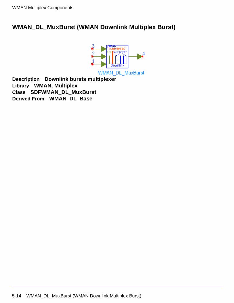
WMAN Multiplex Components
WMAN_DL_MuxBurst (WMAN Downlink Multiplex Burst)
Description Downlink bursts multiplexerLibrary WMAN, MultiplexClass SDFWMAN_DL_MuxBurstDerived From WMAN_DL_Base
5-14 WMAN_DL_MuxBurst (WMAN Downlink Multiplex Burst)
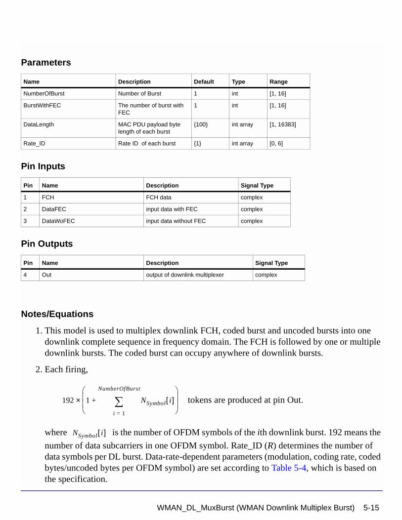
Parameters
Pin Inputs
Pin Outputs
Notes/Equations
1. This model is used to multiplex downlink FCH, coded burst and uncoded bursts into one downlink complete sequence in frequency domain. The FCH is followed by one or multiple downlink bursts. The coded burst can occupy anywhere of downlink bursts.
2. Each firing,
tokens are produced at pin Out.
where is the number of OFDM symbols of the ith downlink burst. 192 means the
number of data subcarriers in one OFDM symbol. Rate_ID (R) determines the number of data symbols per DL burst. Data-rate-dependent parameters (modulation, coding rate, coded bytes/uncoded bytes per OFDM symbol) are set according to Table 5-4, which is based on the specification.
Name Description Default Type Range
NumberOfBurst Number of Burst 1 int [1, 16]
BurstWithFEC The number of burst with FEC
1 int [1, 16]
DataLength MAC PDU payload byte length of each burst
{100} int array [1, 16383]
Rate_ID Rate ID of each burst {1} int array [0, 6]
Pin Name Description Signal Type
1 FCH FCH data complex
2 DataFEC input data with FEC complex
3 DataWoFEC input data without FEC complex
Pin Name Description Signal Type
4 Out output of downlink multiplexer complex
192 1 NSymbol i[ ]i 1=
NumberOfBurst
∑+
×
NSymbol i[ ]
WMAN_DL_MuxBurst (WMAN Downlink Multiplex Burst) 5-15
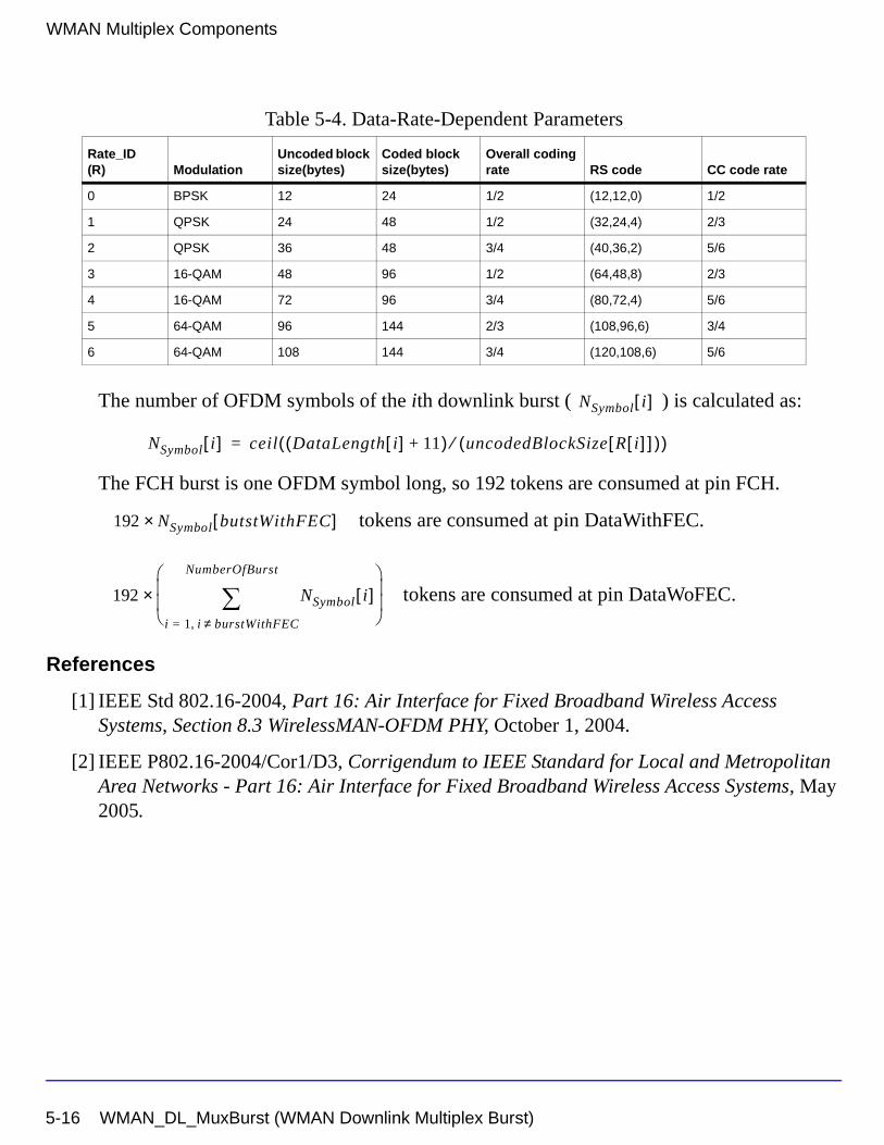
WMAN Multiplex Components
The number of OFDM symbols of the ith downlink burst ( ) is calculated as:
The FCH burst is one OFDM symbol long, so 192 tokens are consumed at pin FCH.
tokens are consumed at pin DataWithFEC.
tokens are consumed at pin DataWoFEC.
References
[1] IEEE Std 802.16-2004, Part 16: Air Interface for Fixed Broadband Wireless Access Systems, Section 8.3 WirelessMAN-OFDM PHY, October 1, 2004.
[2] IEEE P802.16-2004/Cor1/D3, Corrigendum to IEEE Standard for Local and Metropolitan Area Networks - Part 16: Air Interface for Fixed Broadband Wireless Access Systems, May 2005.
Table 5-4. Data-Rate-Dependent Parameters
Rate_ID(R) Modulation
Uncoded block size(bytes)
Coded block size(bytes)
Overall coding rate RS code CC code rate
0 BPSK 12 24 1/2 (12,12,0) 1/2
1 QPSK 24 48 1/2 (32,24,4) 2/3
2 QPSK 36 48 3/4 (40,36,2) 5/6
3 16-QAM 48 96 1/2 (64,48,8) 2/3
4 16-QAM 72 96 3/4 (80,72,4) 5/6
5 64-QAM 96 144 2/3 (108,96,6) 3/4
6 64-QAM 108 144 3/4 (120,108,6) 5/6
NSymbol i[ ]
NSymbol i[ ] ceil DataLength i[ ] 11+( ) uncodedBlockSize R i[ ][ ]( )⁄( )=
192 N× Symbol butstWithFEC[ ]
192 NSymbol i[ ]i 1 i burstWithFEC≠,=
NumberOfBurst
∑
×
5-16 WMAN_DL_MuxBurst (WMAN Downlink Multiplex Burst)
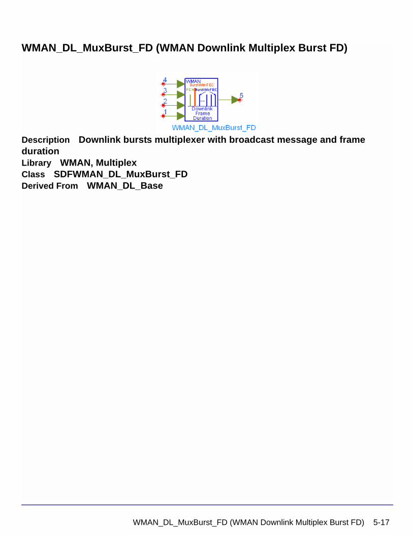
WMAN_DL_MuxBurst_FD (WMAN Downlink Multiplex Burst FD)
Description Downlink bursts multiplexer with broadcast message and frame durationLibrary WMAN, MultiplexClass SDFWMAN_DL_MuxBurst_FDDerived From WMAN_DL_Base
WMAN_DL_MuxBurst_FD (WMAN Downlink Multiplex Burst FD) 5-17
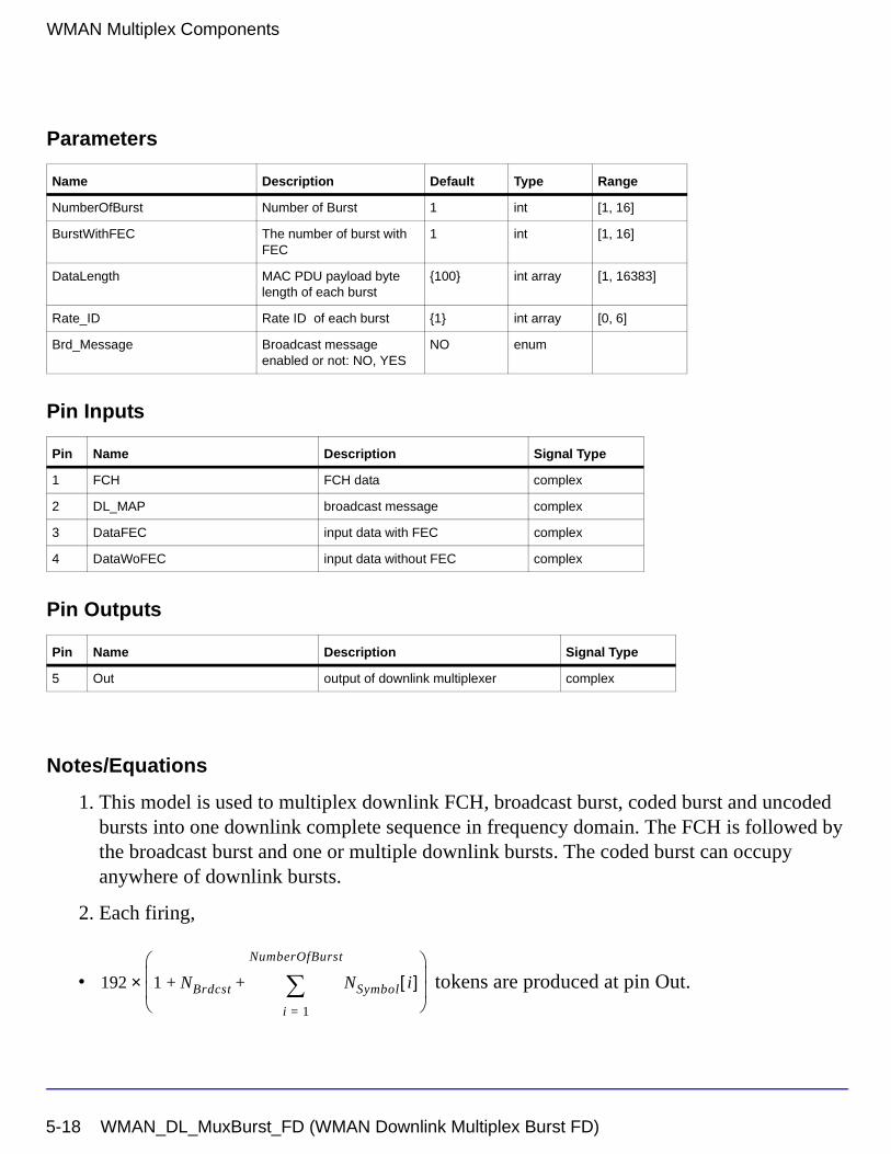
WMAN Multiplex Components
Parameters
Pin Inputs
Pin Outputs
Notes/Equations
1. This model is used to multiplex downlink FCH, broadcast burst, coded burst and uncoded bursts into one downlink complete sequence in frequency domain. The FCH is followed by the broadcast burst and one or multiple downlink bursts. The coded burst can occupy anywhere of downlink bursts.
2. Each firing,
• tokens are produced at pin Out.
Name Description Default Type Range
NumberOfBurst Number of Burst 1 int [1, 16]
BurstWithFEC The number of burst with FEC
1 int [1, 16]
DataLength MAC PDU payload byte length of each burst
{100} int array [1, 16383]
Rate_ID Rate ID of each burst {1} int array [0, 6]
Brd_Message Broadcast message enabled or not: NO, YES
NO enum
Pin Name Description Signal Type
1 FCH FCH data complex
2 DL_MAP broadcast message complex
3 DataFEC input data with FEC complex
4 DataWoFEC input data without FEC complex
Pin Name Description Signal Type
5 Out output of downlink multiplexer complex
192 1 NBrdcst NSymbol i[ ]i 1=
NumberOfBurst
∑+ +
×
5-18 WMAN_DL_MuxBurst_FD (WMAN Downlink Multiplex Burst FD)
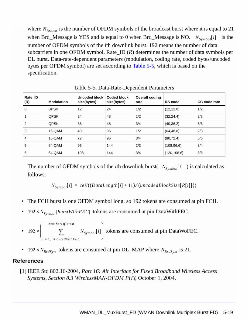
where is the number of OFDM symbols of the broadcast burst where it is equal to 21
when Brd_Message is YES and is equal to 0 when Brd_Message is NO. is the
number of OFDM symbols of the ith downlink burst. 192 means the number of data subcarriers in one OFDM symbol. Rate_ID (R) determines the number of data symbols per DL burst. Data-rate-dependent parameters (modulation, coding rate, coded bytes/uncoded bytes per OFDM symbol) are set according to Table 5-5, which is based on the specification.
The number of OFDM symbols of the ith downlink burst( ) is calculated as
follows:
• The FCH burst is one OFDM symbol long, so 192 tokens are consumed at pin FCH.
• tokens are consumed at pin DataWithFEC.
• tokens are consumed at pin DataWoFEC.
• tokens are consumed at pin DL_MAP where is 21.
References
[1] IEEE Std 802.16-2004, Part 16: Air Interface for Fixed Broadband Wireless Access Systems, Section 8.3 WirelessMAN-OFDM PHY, October 1, 2004.
Table 5-5. Data-Rate-Dependent Parameters
Rate_ID(R) Modulation
Uncoded block size(bytes)
Coded block size(bytes)
Overall coding rate RS code CC code rate
0 BPSK 12 24 1/2 (12,12,0) 1/2
1 QPSK 24 48 1/2 (32,24,4) 2/3
2 QPSK 36 48 3/4 (40,36,2) 5/6
3 16-QAM 48 96 1/2 (64,48,8) 2/3
4 16-QAM 72 96 3/4 (80,72,4) 5/6
5 64-QAM 96 144 2/3 (108,96,6) 3/4
6 64-QAM 108 144 3/4 (120,108,6) 5/6
NBrdcst
NSymbol i[ ]
NSymbol i[ ]
NSymbol i[ ] ceil DataLength i[ ] 11+( ) uncodedBlockSize R i[ ][ ]( )⁄( )=
192 N× Symbol butstWithFEC[ ]
192 NSymbol i[ ]i 1 i burstWithFEC≠,=
NumberOfBurst
∑
×
192 NBrdSym× NBrdSym
WMAN_DL_MuxBurst_FD (WMAN Downlink Multiplex Burst FD) 5-19
WMAN Multiplex Components
[2] IEEE P802.16-2004/Cor1/D5, Corrigendum to IEEE Standard for Local and Metropolitan Area Networks - Part 16: Air Interface for Fixed Broadband Wireless Access Systems, Sept. 2005.
5-20 WMAN_DL_MuxBurst_FD (WMAN Downlink Multiplex Burst FD)
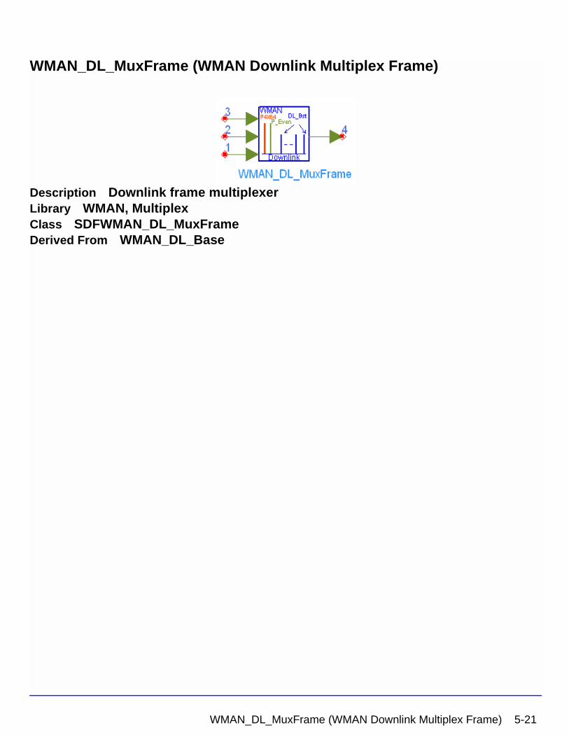
WMAN_DL_MuxFrame (WMAN Downlink Multiplex Frame)
Description Downlink frame multiplexerLibrary WMAN, MultiplexClass SDFWMAN_DL_MuxFrameDerived From WMAN_DL_Base
WMAN_DL_MuxFrame (WMAN Downlink Multiplex Frame) 5-21
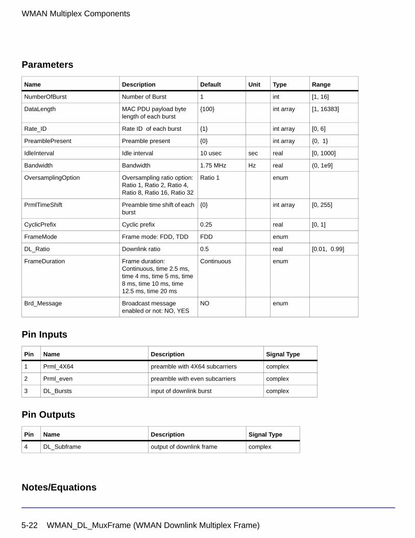
WMAN Multiplex Components
Parameters
Pin Inputs
Pin Outputs
Notes/Equations
Name Description Default Unit Type Range
NumberOfBurst Number of Burst 1 int [1, 16]
DataLength MAC PDU payload byte length of each burst
{100} int array [1, 16383]
Rate_ID Rate ID of each burst {1} int array [0, 6]
PreamblePresent Preamble present {0} int array {0, 1}
IdleInterval Idle interval 10 usec sec real [0, 1000]
Bandwidth Bandwidth 1.75 MHz Hz real (0, 1e9]
OversamplingOption Oversampling ratio option: Ratio 1, Ratio 2, Ratio 4, Ratio 8, Ratio 16, Ratio 32
Ratio 1 enum
PrmlTimeShift Preamble time shift of each burst
{0} int array [0, 255]
CyclicPrefix Cyclic prefix 0.25 real [0, 1]
FrameMode Frame mode: FDD, TDD FDD enum
DL_Ratio Downlink ratio 0.5 real [0.01, 0.99]
FrameDuration Frame duration: Continuous, time 2.5 ms, time 4 ms, time 5 ms, time 8 ms, time 10 ms, time 12.5 ms, time 20 ms
Continuous enum
Brd_Message Broadcast message enabled or not: NO, YES
NO enum
Pin Name Description Signal Type
1 Prml_4X64 preamble with 4X64 subcarriers complex
2 Prml_even preamble with even subcarriers complex
3 DL_Bursts input of downlink burst complex
Pin Name Description Signal Type
4 DL_Subframe output of downlink frame complex
5-22 WMAN_DL_MuxFrame (WMAN Downlink Multiplex Frame)
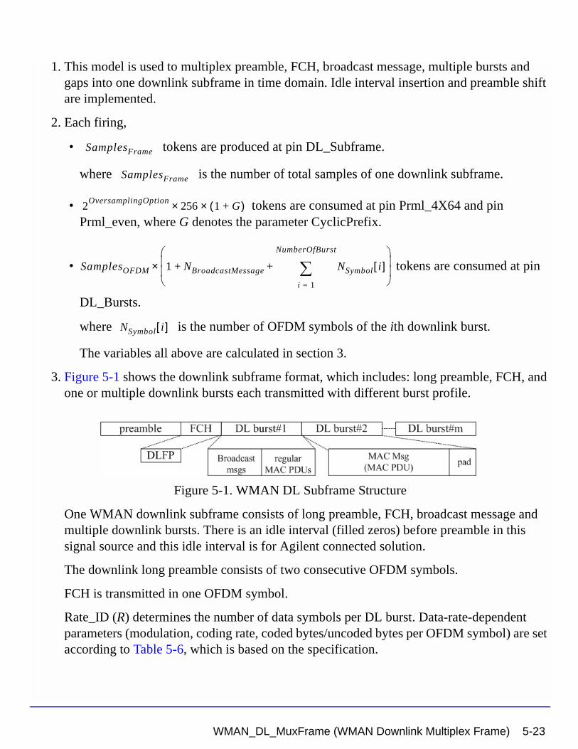
1. This model is used to multiplex preamble, FCH, broadcast message, multiple bursts and gaps into one downlink subframe in time domain. Idle interval insertion and preamble shift are implemented.
2. Each firing,
• tokens are produced at pin DL_Subframe.
where is the number of total samples of one downlink subframe.
• tokens are consumed at pin Prml_4X64 and pin Prml_even, where G denotes the parameter CyclicPrefix.
• tokens are consumed at pin
DL_Bursts.
where is the number of OFDM symbols of the ith downlink burst.
The variables all above are calculated in section 3.
3. Figure 5-1 shows the downlink subframe format, which includes: long preamble, FCH, and one or multiple downlink bursts each transmitted with different burst profile.
Figure 5-1. WMAN DL Subframe Structure
One WMAN downlink subframe consists of long preamble, FCH, broadcast message and multiple downlink bursts. There is an idle interval (filled zeros) before preamble in this signal source and this idle interval is for Agilent connected solution.
The downlink long preamble consists of two consecutive OFDM symbols.
FCH is transmitted in one OFDM symbol.
Rate_ID (R) determines the number of data symbols per DL burst. Data-rate-dependent parameters (modulation, coding rate, coded bytes/uncoded bytes per OFDM symbol) are set according to Table 5-6, which is based on the specification.
SamplesFrame
SamplesFrame
2OversamplingOption
256 1 G+( )××
SamplesOFDM 1 NBroadcastMessage NSymbol i[ ]i 1=
NumberOfBurst
∑+ +
×
NSymbol i[ ]
WMAN_DL_MuxFrame (WMAN Downlink Multiplex Frame) 5-23
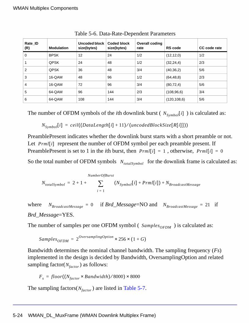
WMAN Multiplex Components
The number of OFDM symbols of the ith downlink burst ( ) is calculated as:
PreamblePresent indicates whether the downlink burst starts with a short preamble or not. Let represent the number of OFDM symbol per each preamble present. If PreamblePresent is set to 1 in the ith burst, then , otherwise,
So the total number of OFDM symbols for the downlink frame is calculated as:
where if Brd_Message=NO and if
Brd_Message=YES.
The number of samples per one OFDM symbol ( ) is calculated as:
Bandwidth determines the nominal channel bandwidth. The sampling frequency (Fs) implemented in the design is decided by Bandwidth, OversamplingOption and related sampling factor( ) as follows:
The sampling factors( ) are listed in Table 5-7.
Table 5-6. Data-Rate-Dependent Parameters
Rate_ID(R) Modulation
Uncoded block size(bytes)
Coded block size(bytes)
Overall coding rate RS code CC code rate
0 BPSK 12 24 1/2 (12,12,0) 1/2
1 QPSK 24 48 1/2 (32,24,4) 2/3
2 QPSK 36 48 3/4 (40,36,2) 5/6
3 16-QAM 48 96 1/2 (64,48,8) 2/3
4 16-QAM 72 96 3/4 (80,72,4) 5/6
5 64-QAM 96 144 2/3 (108,96,6) 3/4
6 64-QAM 108 144 3/4 (120,108,6) 5/6
NSymbol i[ ]
NSymbol i[ ] ceil DataLength i[ ] 11+( ) uncodedBlockSize R i[ ][ ]( )⁄( )=
Prml i[ ]Prml i[ ] 1= Prml i[ ] 0=
NtotalSymbol
NtotalSymbol 2 1 NSymbol i[ ] Prml i[ ]+( ) NBroadcastMessage+
i 1=
NumberOfBurst
∑+ +=
NBroadcastMessage 0= NBroadcastMessage 21=
SamplesOFDM
SamplesOFDM 2OversamplingOption
256× 1 G+( )×=
Nfactor
Fs floor Nfactor Bandwidth×( ) 8000⁄( ) 8000×=
Nfactor
5-24 WMAN_DL_MuxFrame (WMAN Downlink Multiplex Frame)
The samples of IdleInterval( ) is calculated as follows:
So, the total samples of one downlink frame is
where Fs is the sampling frequency. FrameDuration can be selected as 2.5 ms, 4 ms, 5 ms, 8
ms, 10 ms, 12.5 ms and 20 ms according to the specification.
4. When FrameDuration=Continuous, both parameters FrameMode and DL_Ratio are inactive. This model just combines idle interval, preamble, FCH, broadcast message and multiple bursts as one signal stream (not the real downlink subframe) and outputs this stream. When FrameDuration<>Continuous, both parameters FrameMode and DL_Ratio are active. This model combines idle interval, preamble, FCH, broadcast message and multiple bursts and gaps as one downlink subframe and outputs this downlink subframe.
When FrameMode=FDD, the DL_Ratio is inactive and the full subframe can be loaded the downlink signal. The first part is idle interval ( the number of zeros is Samplesidle ), the
second part is the downlink signal (the number is ), the third
part is filled with zeros.
Table 5-7. Sampling Factor Requirement
Sampling factor n Bandwidth
8/7 For channel bandwidths that are a multiple of 1.75 MHz
86/75 else for channel bandwidths that are a multiple of 1.5 MHz
144/125 else for channel bandwidths that are a multiple of 1.25 MHz
316/275 else for channel bandwidths that are a multiple of 2.75 MHz
57/50 else for channel bandwidths that are a multiple of 2.0 MHz
8/7 else for channel bandwidths not otherwise specified
Samplesidle
Samplesidle IdleInterval 2OversamplingOption
Fs××=
SamplesFrame
SamplesFrame
Samplesidle NtotalSymbol SamplesOFDM×+
if FrameDuration Continuous=
FrameDuration Fs× 2OversamplingOption×
if FrameDuration Continuous◊
=
NtotalSymbol S× amplesFrame
WMAN_DL_MuxFrame (WMAN Downlink Multiplex Frame) 5-25
WMAN Multiplex Components
When FrameMode=TDD, the DL_Ratio is active. This DL_Ratio (or DLRatio in equation) parameter determines where to put the downlink subframe. DL_Ratio splits the frame into two parts. The first part (The number of samples is
) is to transmit downlink signal
and the second part should be filled with zeros.
References
[1] IEEE Std 802.16-2004, Part 16: Air Interface for Fixed Broadband Wireless Access Systems, Section 8.3 WirelessMAN-OFDM PHY, October 1, 2004.
[2] IEEE P802.16-2004/Cor1/D3, Corrigendum to IEEE Standard for Local and Metropolitan Area Networks - Part 16: Air Interface for Fixed Broadband Wireless Access Systems, May 2005.
int FrameDuration Fs× 2OversamplingOption
DLRatio××( )
5-26 WMAN_DL_MuxFrame (WMAN Downlink Multiplex Frame)
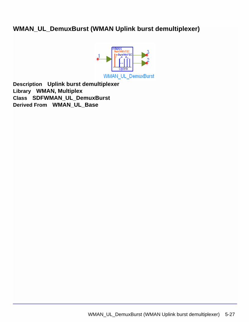
WMAN_UL_DemuxBurst (WMAN Uplink burst demultiplexer)
Description Uplink burst demultiplexerLibrary WMAN, MultiplexClass SDFWMAN_UL_DemuxBurstDerived From WMAN_UL_Base
WMAN_UL_DemuxBurst (WMAN Uplink burst demultiplexer) 5-27
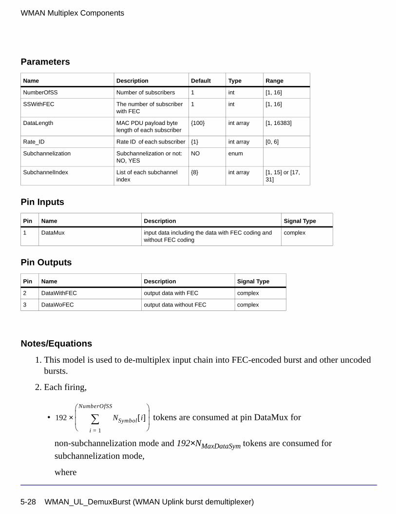
WMAN Multiplex Components
Parameters
Pin Inputs
Pin Outputs
Notes/Equations
1. This model is used to de-multiplex input chain into FEC-encoded burst and other uncoded bursts.
2. Each firing,
• tokens are consumed at pin DataMux for
non-subchannelization mode and 192×NMaxDataSym tokens are consumed for
subchannelization mode,
where
Name Description Default Type Range
NumberOfSS Number of subscribers 1 int [1, 16]
SSWithFEC The number of subscriber with FEC
1 int [1, 16]
DataLength MAC PDU payload byte length of each subscriber
{100} int array [1, 16383]
Rate_ID Rate ID of each subscriber {1} int array [0, 6]
Subchannelization Subchannelization or not: NO, YES
NO enum
SubchannelIndex List of each subchannel index
{8} int array [1, 15] or [17, 31]
Pin Name Description Signal Type
1 DataMux input data including the data with FEC coding and without FEC coding
complex
Pin Name Description Signal Type
2 DataWithFEC output data with FEC complex
3 DataWoFEC output data without FEC complex
192 NSymbol i[ ]i 1=
NumberOfSS
∑
×
5-28 WMAN_UL_DemuxBurst (WMAN Uplink burst demultiplexer)
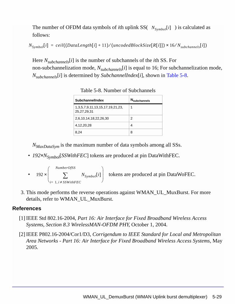
The number of OFDM data symbols of ith uplink SS( ) is calculated as
follows:
Here Nsubchannels[i] is the number of subchannels of the ith SS. For
non-subchannelization mode, Nsubchannels[i] is equal to 16; For subchannelization mode,
Nsubchannels[i] is determined by SubchannelIndex[i], shown in Table 5-8.
NMaxDataSym is the maximum number of data symbols among all SSs.
• 192×NSymbol[SSWithFEC] tokens are produced at pin DataWithFEC.
• tokens are produced at pin DataWoFEC.
3. This mode performs the reverse operations against WMAN_UL_MuxBurst. For more details, refer to WMAN_UL_MuxBurst.
References
[1] IEEE Std 802.16-2004, Part 16: Air Interface for Fixed Broadband Wireless Access Systems, Section 8.3 WirelessMAN-OFDM PHY, October 1, 2004.
[2] IEEE P802.16-2004/Cor1/D3, Corrigendum to IEEE Standard for Local and Metropolitan Area Networks - Part 16: Air Interface for Fixed Broadband Wireless Access Systems, May 2005.
Table 5-8. Number of Subchannels
SubchannelIndex Nsubchannels
1,3,5,7,9,11,13,15,17,19,21,23,25,27,29,31
1
2,6,10,14,18,22,26,30 2
4,12,20,28 4
8,24 8
NSymbol i[ ]
NSymbol i[ ] ceil DataLength i[ ] 11+( ) uncodedBlockSize R i[ ][ ]( )⁄ 16 Nsubchannels⁄× i[ ]( )=
192 NSymbol i[ ]i 1= i, SSWithFEC≠
NumberOfSS
∑
×
WMAN_UL_DemuxBurst (WMAN Uplink burst demultiplexer) 5-29
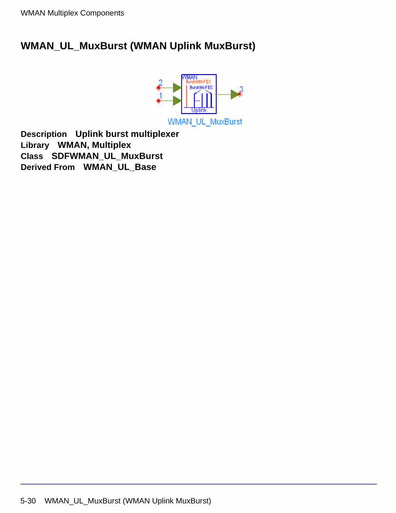
WMAN Multiplex Components
WMAN_UL_MuxBurst (WMAN Uplink MuxBurst)
Description Uplink burst multiplexerLibrary WMAN, MultiplexClass SDFWMAN_UL_MuxBurstDerived From WMAN_UL_Base
5-30 WMAN_UL_MuxBurst (WMAN Uplink MuxBurst)
Parameters
Pin Inputs
Pin Outputs
Notes/Equations
1. This model is used to multiplex FEC-encoded SS and other uncoded SSs into a complete chain.
2. Each firing,
• 192×NSymbol[SSWithFEC] tokens are consumed at pin DataWithFEC.
• tokens are consumed at pin DataWoFEC.
Name Description Default Type Range
NumberOfSS Number of subscribers 1 int [1, 16]
SSWithFEC The number of subscriber with FEC
1 int [1, 16]
DataLength MAC PDU payload byte length of each subscriber
{100} int array [1, 16383]
Rate_ID Rate ID of each subscriber {1} int array [0, 6]
Subchannelization Subchannelization or not: NO, YES
NO enum
SubchannelIndex List of each subchannel index
{8} int array [1, 15] or [17, 31]
Pin Name Description Signal Type
1 DataWithFEC input data with FEC complex
2 DataWoFEC input data without FEC complex
Pin Name Description Signal Type
3 DataMux output data including the data with FEC coding and without FEC coding
complex
192 NSymbol i[ ]i 1= i, SSWithFEC≠
NumberOfSS
∑
×
WMAN_UL_MuxBurst (WMAN Uplink MuxBurst) 5-31
WMAN Multiplex Components
• tokens are produced at pin DataMux for
non-subchannelization mode and 192×NMaxDataSym tokens are produced for
subchannelization mode.
where
The number of OFDM data symbols of ith uplink SS( ) is calculated as
follows:
Here Nsubchannels[i] is the number of subchannels of the ith SS. For
non-subchannelization mode, Nsubchannels[i] is equal to 16; For subchannelization mode,
Nsubchannels[i] is determined by SubchannelIndex[i], shown in Table 5-9.
NMaxDataSym is the maximum number of data symbols among all SSs.
3. The OFDM data symbol has 192 data subcarriers. In non-subchannelization mode, The SS with FEC-encoded is inserted into SSs without FEC-encoded to form a bursts chain according to the parameter of SSWithFEC, where each SS occupies a burst.
In subchannelization mode, all the SSs share one burst, which has NMaxDataSym OFDM data
symbols. Each SS is assigned to a subchannel index which specifies the subcarriers that used by the SS. In this model, all the SSs' data will be mapped into corresponding data subcarriers, while other unused data subcarriers are set with zeros. Note that each SS has different length of data symbols which is determined by Datalength and Rate_ID, so in the case that, one SS has data to transmit and another SS has no more data to transmit in the same data symbol, the data subcarriers allocated to the SS which has no more data to transmit will be filled with zeros.
Table 5-9. Number of Subchannels
SubchannelIndex Nsubchannels
1,3,5,7,9,11,13,15,17,19,21,23,25,27,29,31
1
2,6,10,14,18,22,26,30 2
4,12,20,28 4
8,24 8
192 NSymbol i[ ]i 1=
NumberOfSS
∑
×
NSymbol i[ ]
NSymbol i[ ] ceil DataLength i[ ] 11+( ) uncodedBlockSize R i[ ][ ]( )⁄ 16 Nsubchannels⁄× i[ ]( )=
5-32 WMAN_UL_MuxBurst (WMAN Uplink MuxBurst)
References
[1] IEEE Std 802.16-2004, Part 16: Air Interface for Fixed Broadband Wireless Access Systems, Section 8.3 WirelessMAN-OFDM PHY, October 1, 2004.
[2] IEEE P802.16-2004/Cor1/D3, Corrigendum to IEEE Standard for Local and Metropolitan Area Networks - Part 16: Air Interface for Fixed Broadband Wireless Access Systems, May 2005.
WMAN_UL_MuxBurst (WMAN Uplink MuxBurst) 5-33
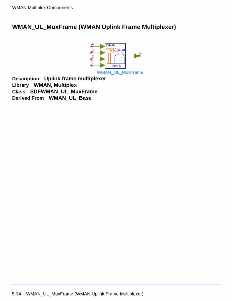
WMAN Multiplex Components
WMAN_UL_MuxFrame (WMAN Uplink Frame Multiplexer)
Description Uplink frame multiplexerLibrary WMAN, MultiplexClass SDFWMAN_UL_MuxFrameDerived From WMAN_UL_Base
5-34 WMAN_UL_MuxFrame (WMAN Uplink Frame Multiplexer)
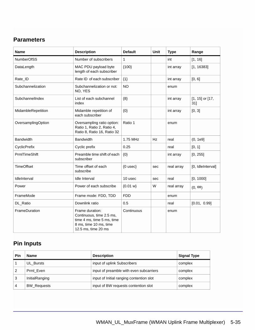
Parameters
Pin Inputs
Name Description Default Unit Type Range
NumberOfSS Number of subscribers 1 int [1, 16]
DataLength MAC PDU payload byte length of each subscriber
{100} int array [1, 16383]
Rate_ID Rate ID of each subscriber {1} int array [0, 6]
Subchannelization Subchannelization or not: NO, YES
NO enum
SubchannelIndex List of each subchannel index
{8} int array [1, 15] or [17, 31]
MidambleRepetition Midamble repetition of each subscriber
{0} int array [0, 3]
OversamplingOption Oversampling ratio option: Ratio 1, Ratio 2, Ratio 4, Ratio 8, Ratio 16, Ratio 32
Ratio 1 enum
Bandwidth Bandwidth 1.75 MHz Hz real (0, 1e9]
CyclicPrefix Cyclic prefix 0.25 real [0, 1]
PrmlTimeShift Preamble time shift of each subscriber
{0} int array [0, 255]
TimeOffset Time offset of each subscribe
{0 usec} sec real array [0, IdleInterval]
IdleInterval Idle Interval 10 usec sec real [0, 1000]
Power Power of each subscribe {0.01 w} W real array (0, ∞)
FrameMode Frame mode: FDD, TDD FDD enum
DL_Ratio Downlink ratio 0.5 real [0.01, 0.99]
FrameDuration Frame duration: Continuous, time 2.5 ms, time 4 ms, time 5 ms, time 8 ms, time 10 ms, time 12.5 ms, time 20 ms
Continuous enum
Pin Name Description Signal Type
1 UL_Bursts input of uplink Subscribers complex
2 Prml_Even input of preamble with even subcarriers complex
3 InitialRanging input of Initial ranging contention slot complex
4 BW_Requests input of BW requests contention slot complex
WMAN_UL_MuxFrame (WMAN Uplink Frame Multiplexer) 5-35
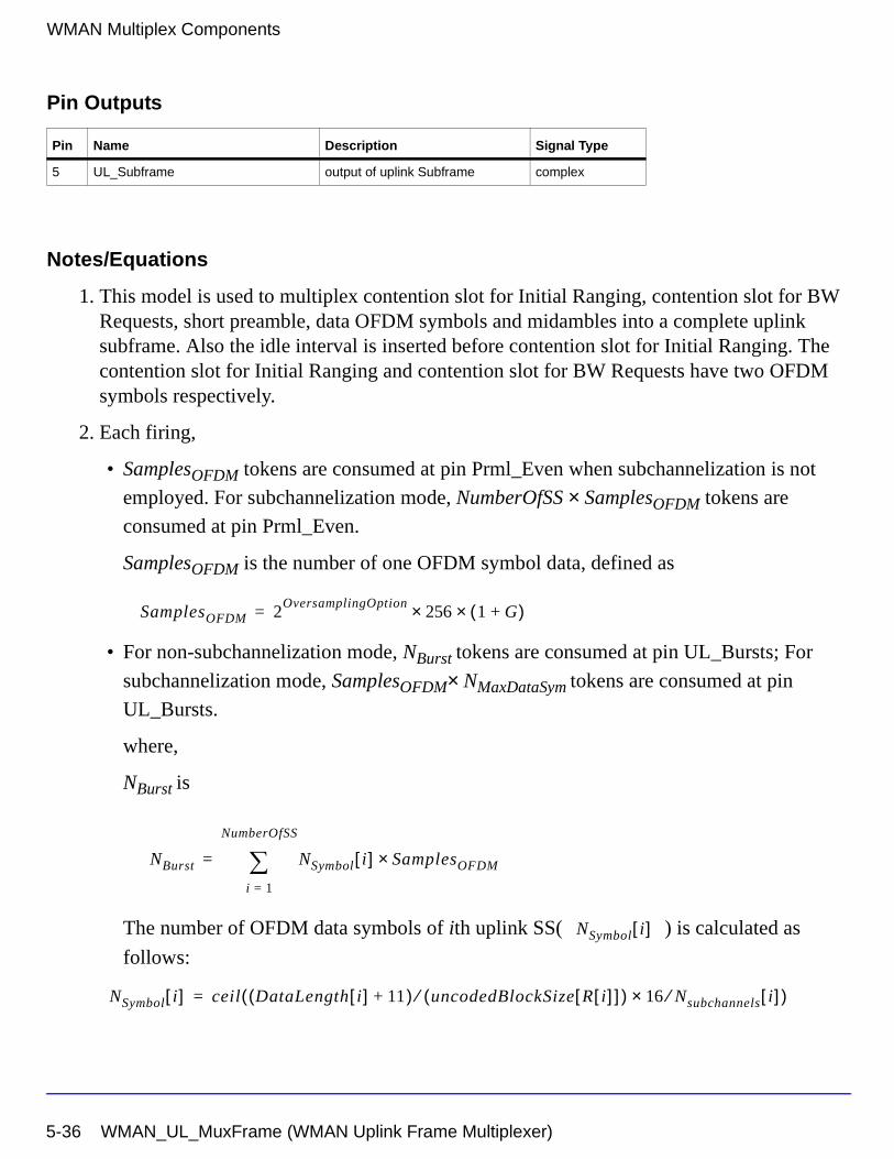
WMAN Multiplex Components
Pin Outputs
Notes/Equations
1. This model is used to multiplex contention slot for Initial Ranging, contention slot for BW Requests, short preamble, data OFDM symbols and midambles into a complete uplink subframe. Also the idle interval is inserted before contention slot for Initial Ranging. The contention slot for Initial Ranging and contention slot for BW Requests have two OFDM symbols respectively.
2. Each firing,
• SamplesOFDM tokens are consumed at pin Prml_Even when subchannelization is not
employed. For subchannelization mode, NumberOfSS × SamplesOFDM tokens are
consumed at pin Prml_Even.
SamplesOFDM is the number of one OFDM symbol data, defined as
• For non-subchannelization mode, NBurst tokens are consumed at pin UL_Bursts; For
subchannelization mode, SamplesOFDM× NMaxDataSym tokens are consumed at pin
UL_Bursts.
where,
NBurst is
The number of OFDM data symbols of ith uplink SS( ) is calculated as
follows:
Pin Name Description Signal Type
5 UL_Subframe output of uplink Subframe complex
SamplesOFDM 2OversamplingOption
256× 1 G+( )×=
NBurst NSymbol i[ ] SamplesOFDM×i 1=
NumberOfSS
∑=
NSymbol i[ ]
NSymbol i[ ] ceil DataLength i[ ] 11+( ) uncodedBlockSize R i[ ][ ]( )⁄ 16 Nsubchannels⁄× i[ ]( )=
5-36 WMAN_UL_MuxFrame (WMAN Uplink Frame Multiplexer)
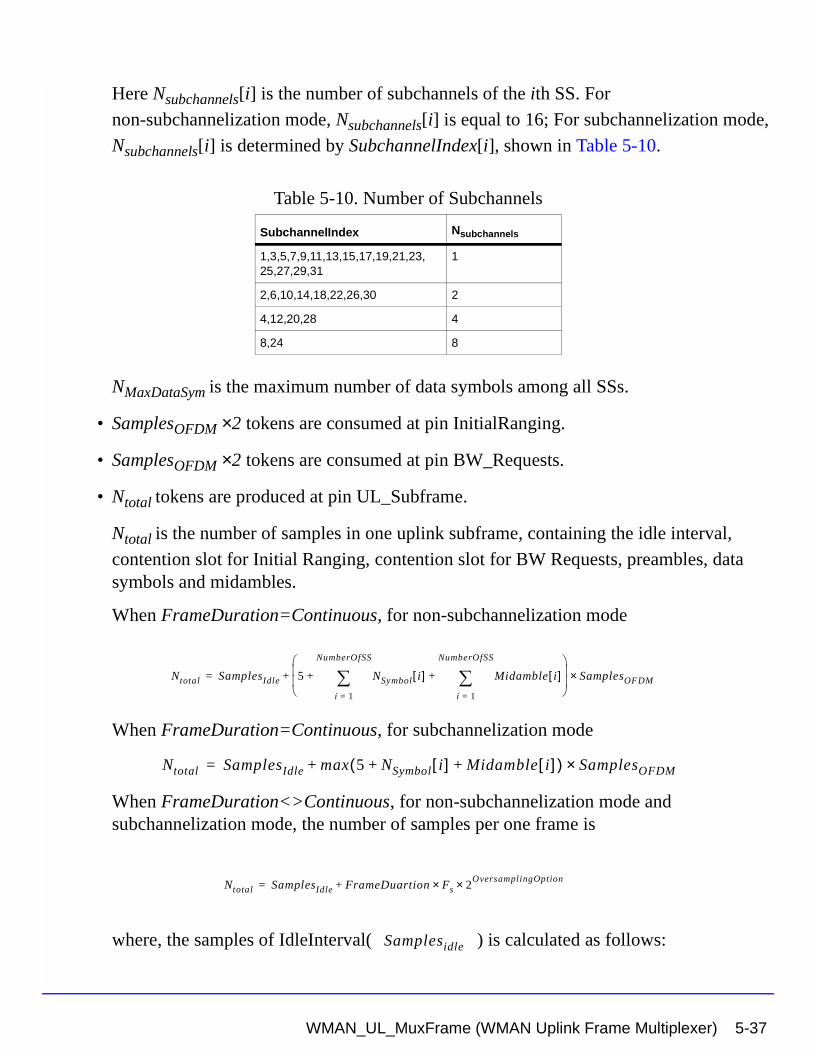
Here Nsubchannels[i] is the number of subchannels of the ith SS. For
non-subchannelization mode, Nsubchannels[i] is equal to 16; For subchannelization mode,
Nsubchannels[i] is determined by SubchannelIndex[i], shown in Table 5-10.
NMaxDataSym is the maximum number of data symbols among all SSs.
• SamplesOFDM ×2 tokens are consumed at pin InitialRanging.
• SamplesOFDM ×2 tokens are consumed at pin BW_Requests.
• Ntotal tokens are produced at pin UL_Subframe.
Ntotal is the number of samples in one uplink subframe, containing the idle interval,
contention slot for Initial Ranging, contention slot for BW Requests, preambles, data symbols and midambles.
When FrameDuration=Continuous, for non-subchannelization mode
When FrameDuration=Continuous, for subchannelization mode
When FrameDuration<>Continuous, for non-subchannelization mode and subchannelization mode, the number of samples per one frame is
where, the samples of IdleInterval( ) is calculated as follows:
Table 5-10. Number of Subchannels
SubchannelIndex Nsubchannels
1,3,5,7,9,11,13,15,17,19,21,23,25,27,29,31
1
2,6,10,14,18,22,26,30 2
4,12,20,28 4
8,24 8
Ntotal SamplesIdle 5 NSymbol i[ ]i 1=
NumberOfSS
∑ Midamble i[ ]i 1=
NumberOfSS
∑+ +
SamplesOFDM×+=
Ntotal SamplesIdle max 5 NSymbol i[ ] Midamble i[ ]+ +( ) SamplesOFDM×+=
Ntotal SamplesIdle FrameDuartion Fs× 2OversamplingOption×+=
Samplesidle
WMAN_UL_MuxFrame (WMAN Uplink Frame Multiplexer) 5-37
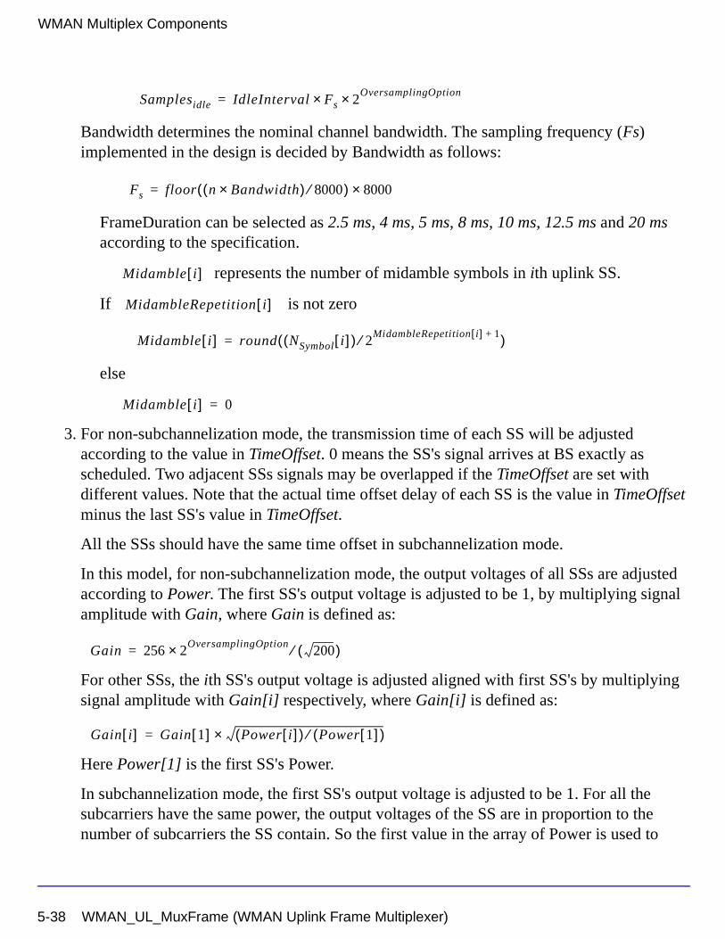
WMAN Multiplex Components
Bandwidth determines the nominal channel bandwidth. The sampling frequency (Fs) implemented in the design is decided by Bandwidth as follows:
FrameDuration can be selected as 2.5 ms, 4 ms, 5 ms, 8 ms, 10 ms, 12.5 ms and 20 ms according to the specification.
represents the number of midamble symbols in ith uplink SS.
If is not zero
else
3. For non-subchannelization mode, the transmission time of each SS will be adjusted according to the value in TimeOffset. 0 means the SS's signal arrives at BS exactly as scheduled. Two adjacent SSs signals may be overlapped if the TimeOffset are set with different values. Note that the actual time offset delay of each SS is the value in TimeOffset minus the last SS's value in TimeOffset.
All the SSs should have the same time offset in subchannelization mode.
In this model, for non-subchannelization mode, the output voltages of all SSs are adjusted according to Power. The first SS's output voltage is adjusted to be 1, by multiplying signal amplitude with Gain, where Gain is defined as:
For other SSs, the ith SS's output voltage is adjusted aligned with first SS's by multiplying signal amplitude with Gain[i] respectively, where Gain[i] is defined as:
Here Power[1] is the first SS's Power.
In subchannelization mode, the first SS's output voltage is adjusted to be 1. For all the subcarriers have the same power, the output voltages of the SS are in proportion to the number of subcarriers the SS contain. So the first value in the array of Power is used to
Samplesidle IdleInterval Fs× 2OversamplingOption×=
Fs floor n Bandwidth×( ) 8000⁄( ) 8000×=
Midamble i[ ]
MidambleRepetition i[ ]
Midamble i[ ] round NSymbol i[ ]( ) 2MidambleRepetition i[ ] 1+⁄( )=
Midamble i[ ] 0=
Gain 256 2OversamplingOption
200( )⁄×=
Gain i[ ] Gain 1[ ] Power i[ ]( ) Power 1[ ]( )⁄×=
5-38 WMAN_UL_MuxFrame (WMAN Uplink Frame Multiplexer)
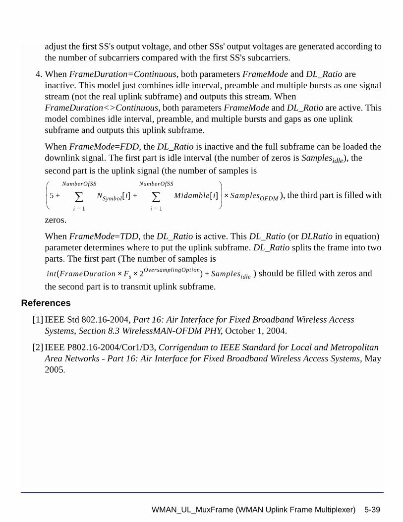
adjust the first SS's output voltage, and other SSs' output voltages are generated according to the number of subcarriers compared with the first SS's subcarriers.
4. When FrameDuration=Continuous, both parameters FrameMode and DL_Ratio are inactive. This model just combines idle interval, preamble and multiple bursts as one signal stream (not the real uplink subframe) and outputs this stream. When FrameDuration<>Continuous, both parameters FrameMode and DL_Ratio are active. This model combines idle interval, preamble, and multiple bursts and gaps as one uplink subframe and outputs this uplink subframe.
When FrameMode=FDD, the DL_Ratio is inactive and the full subframe can be loaded the downlink signal. The first part is idle interval (the number of zeros is Samplesidle), the
second part is the uplink signal (the number of samples is
), the third part is filled with
zeros.
When FrameMode=TDD, the DL_Ratio is active. This DL_Ratio (or DLRatio in equation) parameter determines where to put the uplink subframe. DL_Ratio splits the frame into two parts. The first part (The number of samples is
) should be filled with zeros and
the second part is to transmit uplink subframe.
References
[1] IEEE Std 802.16-2004, Part 16: Air Interface for Fixed Broadband Wireless Access Systems, Section 8.3 WirelessMAN-OFDM PHY, October 1, 2004.
[2] IEEE P802.16-2004/Cor1/D3, Corrigendum to IEEE Standard for Local and Metropolitan Area Networks - Part 16: Air Interface for Fixed Broadband Wireless Access Systems, May 2005.
5 NSymbol i[ ]i 1=
NumberOfSS
∑ Midamble i[ ]i 1=
NumberOfSS
∑+ +
SamplesOFDM×
int FrameDuration Fs× 2OversamplingOption×( ) Samplesidle+
WMAN_UL_MuxFrame (WMAN Uplink Frame Multiplexer) 5-39
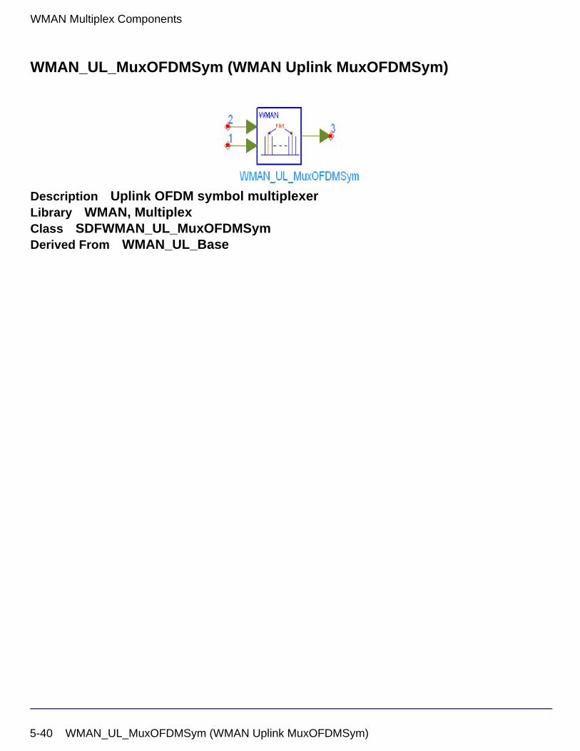
WMAN Multiplex Components
WMAN_UL_MuxOFDMSym (WMAN Uplink MuxOFDMSym)
Description Uplink OFDM symbol multiplexerLibrary WMAN, MultiplexClass SDFWMAN_UL_MuxOFDMSymDerived From WMAN_UL_Base
5-40 WMAN_UL_MuxOFDMSym (WMAN Uplink MuxOFDMSym)
Parameters
Pin Inputs
Pin Outputs
Notes/Equations
1. This model is used to multiplex data and pilot subcarriers into the OFDM symbol in the uplink.
2. Each firing,
• For non-subchannelization mode, 192 tokens are consumed at pin Data, and for subchannelization mode, 192×NMaxDataSym tokens are consumed at pin Data.
where
NMaxDataSym is the maximum number of data symbols among all SSs.
The number of OFDM data symbols of ith uplink SS( ) is calculated as
follows:
Name Description Default Type Range
NumberOfSS Number of subscribers 1 int [1, 16]
DataLength MAC PDU payload byte length of each subscriber
{100} int array [1, 16383]
Rate_ID Rate ID of each subscriber {1} int array [0, 6]
Subchannelization Subchannelization or not: NO, YES
NO enum
SubchannelIndex List of each subchannel index
{8} int array [1, 15] or [17, 31]
Pin Name Description Signal Type
1 Data input of data carriers complex
2 Pilot input of continual pilot value complex
Pin Name Description Signal Type
3 Out output of OFDM symbol complex
NMaxDataSym max NSymbol i[ ]( )=
NSymbol i[ ]
5-41
WMAN Multiplex Components
Here Nsubchannels[i] is the number of subchannels of the ith SS. For
non-subchannelization mode, Nsubchannels[i] is equal to 16; For subchannelization mode,
Nsubchannels[i] is determined by SubchannelIndex[i], shown in Table 5-11.
• For non-subchannelization mode, 1 tokens are consumed at pin Pilot, and for subchannelization mode, NMaxDataSym tokens are consumed at pin Pilot.
• For non-subchannelization mode, 200 tokens are produced at pin Out, and for subchannelization mode, 200×NMaxDataSym tokens are produced at pin Out.
3. In non-subchannelization mode, the data at pin Data are mapped into data subcarriers. In every OFDM symbol, 192 data are mapped. The frequency offset indices of data subcarriers are from -100 to 100, excluding DC subcarriers of index 0 and pilot subcarriers. The frequency offset indices of pilot subcarriers are {-88, -63, -38, -13, 13, 38, 63, 88}. The basic values on pilot subcarriers are BasicValue = {1, -1, 1, -1, 1, 1, 1, 1}. Finally the values BasicValue×Pilot are mapped into pilot subcarriers, where Pilot is the value at pin Pilot.
In subchannelization mode, the data at pin Data are also mapped into data subcarriers. In every OFDM symbol, 192 data are mapped. The values on pilot subcarriers depend on corresponding subchannels. The relation of subchannel index with pilot subcarriers allocated is shown in Figure 5-2. Note that pilot subcarriers are allocated only if two or more subchannels are allocated. The values BasicValue×Pilot are only mapped into the pilot subcarriers which the active SSs contain, while other non-active pilot subcarriers are filled with zeros. The values BasicValue×Pilot is the same as those in non-subchannelization mode.
Table 5-11. Number of Subchannels
SubchannelIndex Nsubchannels
1,3,5,7,9,11,13,15,17,19,21,23,25,27,29,31
1
2,6,10,14,18,22,26,30 2
4,12,20,28 4
8,24 8
NSymbol i[ ] ceil DataLength i[ ] 11+( ) uncodedBlockSize R i[ ][ ]( )⁄ 16 Nsubchannels⁄× i[ ]( )=
5-42
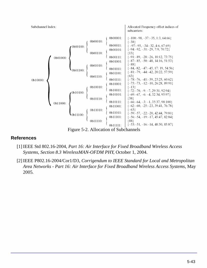
Figure 5-2. Allocation of Subchannels
References
[1] IEEE Std 802.16-2004, Part 16: Air Interface for Fixed Broadband Wireless Access Systems, Section 8.3 WirelessMAN-OFDM PHY, October 1, 2004.
[2] IEEE P802.16-2004/Cor1/D3, Corrigendum to IEEE Standard for Local and Metropolitan Area Networks - Part 16: Air Interface for Fixed Broadband Wireless Access Systems, May 2005.
5-43

WMAN Multiplex Components
5-44
Chapter 6: WMAN Receiver ComponentsThe receiver models provide channel estimator, frame synchronization and frequency synchronization, top level baseband receivers and top level RF receivers.
• WMAN_DL_ChEstimator: Downlink channel estimator
• WMAN_DL_DemuxFrame: Downlink frame de-multiplexer with frequency offset compensation, cyclic prefix removed
• WMAN_DL_DemuxFrame_FD: Downlink frame de-multiplexer with frame duration
• WMAN_DL_FrameSync: Downlink frame synchronizer
• WMAN_DL_FreqSync: Downlink frequency synchronizer
• WMAN_DL_PhaseTracker: Downlink phase tracker
• WMAN_Demapper: Soft demapper
• WMAN_UL_ChEstimator: Uplink channel estimator
• WMAN_UL_DemuxFrame: Uplink frame de-multiplexer with frequency offset compensation, cyclic prefix removed
• WMAN_UL_DemuxFrame_FD: Uplink frame de-multiplexer with frame duration
• WMAN_UL_FrameSync: Uplink frame synchronizer
• WMAN_UL_FreqSync: Uplink frequency synchronizer
• WMAN_UL_PhaseTracker: Uplink phase tracker
• WMAN_DL_Receiver: Downlink baseband receiver
• WMAN_DL_Receiver_RF: Downlink RF receiver
• WMAN_DL_Rx_FD: Downlink baseband receiver with frame duration
• WMAN_DL_Rx_FD_RF: Downlink RF receiver with frame duration
• WMAN_UL_Receiver: Uplink baseband receiver
• WMAN_UL_Receiver_RF: Uplink RF receiver
• WMAN_UL_Rx_FD: Downlink baseband receiver with frame duration
• WMAN_UL_Rx_FD_RF: Downlink RF receiver with frame duration
6-1
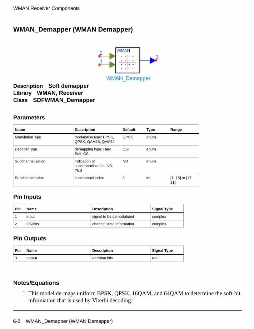
WMAN Receiver Components
WMAN_Demapper (WMAN Demapper)
Description Soft demapperLibrary WMAN, ReceiverClass SDFWMAN_Demapper
Parameters
Pin Inputs
Pin Outputs
Notes/Equations
1. This model de-maps uniform BPSK, QPSK, 16QAM, and 64QAM to determine the soft-bit information that is used by Viterbi decoding.
Name Description Default Type Range
ModulationType modulation type: BPSK, QPSK, QAM16, QAM64
QPSK enum
DecoderType demapping type: Hard, Soft, CSI
CSI enum
Subchannelization Indication of subchannelization: NO, YES
NO enum
SubchannelIndex subchannel index 8 int [1, 15] or [17, 31]
Pin Name Description Signal Type
1 input signal to be demodulated complex
2 CSIBits channel state information complex
Pin Name Description Signal Type
3 output decision bits real
6-2 WMAN_Demapper (WMAN Demapper)
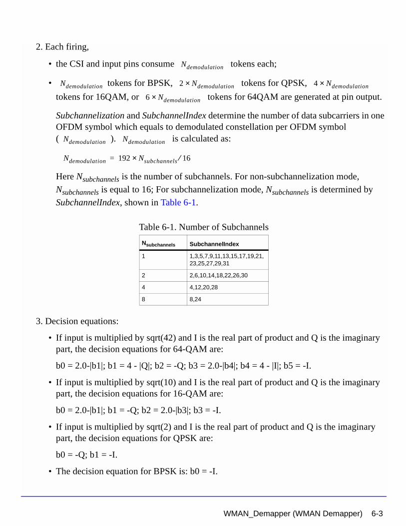
2. Each firing,
• the CSI and input pins consume tokens each;
• tokens for BPSK, tokens for QPSK,
tokens for 16QAM, or tokens for 64QAM are generated at pin output.
Subchannelization and SubchannelIndex determine the number of data subcarriers in one OFDM symbol which equals to demodulated constellation per OFDM symbol ( ). is calculated as:
Here Nsubchannels is the number of subchannels. For non-subchannelization mode,
Nsubchannels is equal to 16; For subchannelization mode, Nsubchannels is determined by
SubchannelIndex, shown in Table 6-1.
3. Decision equations:
• If input is multiplied by sqrt(42) and I is the real part of product and Q is the imaginary part, the decision equations for 64-QAM are:
b0 = 2.0-|b1|; b1 = 4 - |Q|; b2 = -Q; b3 = 2.0-|b4|; b4 = 4 - |I|; b5 = -I.
• If input is multiplied by sqrt(10) and I is the real part of product and Q is the imaginary part, the decision equations for 16-QAM are:
b0 = 2.0-|b1|; b1 = -Q; b2 = 2.0-|b3|; b3 = -I.
• If input is multiplied by sqrt(2) and I is the real part of product and Q is the imaginary part, the decision equations for QPSK are:
b0 = -Q; b1 = -I.
• The decision equation for BPSK is: b0 = -I.
Table 6-1. Number of Subchannels
Nsubchannels SubchannelIndex
1 1,3,5,7,9,11,13,15,17,19,21,23,25,27,29,31
2 2,6,10,14,18,22,26,30
4 4,12,20,28
8 8,24
Ndemodulation
Ndemodulation 2 Ndemodulation× 4 Ndemodulation×
6 Ndemodulation×
Ndemodulation Ndemodulation
Ndemodulation 192 Nsubchannels 16⁄×=
WMAN_Demapper (WMAN Demapper) 6-3
WMAN Receiver Components
4. Based on the above calculations, let any one of decision bits equal b:
• when DecoderType is set to Hard, if b < 0, -1.0 is output, otherwise 1.0 is output.
• when DecoderType is set to Soft, if b < -1.0, -1.0 is output; if b > 1.0, 1.0 is output, otherwise, b is output directly.
• when DecoderType is set to CSI, b is multiplied by CSI (normalized channel response estimation) and output. Different bits which form one constellation have the same CSI.
References
[1] IEEE Std 802.16-2004, Part 16: Air Interface for Fixed Broadband Wireless Access Systems, Section 8.3 WirelessMAN-OFDM PHY, October 1, 2004.
[2] IEEE P802.16-2004/Cor1/D3, Corrigendum to IEEE Standard for Local and Metropolitan Area Networks - Part 16: Air Interface for Fixed Broadband Wireless Access Systems, May 2005.
6-4 WMAN_Demapper (WMAN Demapper)
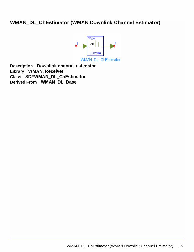
WMAN_DL_ChEstimator (WMAN Downlink Channel Estimator)
Description Downlink channel estimatorLibrary WMAN, ReceiverClass SDFWMAN_DL_ChEstimatorDerived From WMAN_DL_Base
WMAN_DL_ChEstimator (WMAN Downlink Channel Estimator) 6-5
WMAN Receiver Components
Parameters
Pin Inputs
Pin Outputs
Notes/Equations
1. This model is used to estimate WMAN downlink channel impulse response (CIR) based on the pilot channels and output the estimated channel impulse response (CIR) on the active subcarriers.
2. Each firing,
• tokens are consumed at pin input.
where is the number of OFDM symbol per each preamble present. If
PreamblePresent is set to 1 in the ith burst, then , otherwise,
Name Description Default Type Range
NumberOfBurst Number of Burst 1 int [1, 16]
DataLength MAC PDU payload byte length of each burst
{100} int array [1, 16383]
Rate_ID Rate ID of each burst {1} int array [0, 6]
PreamblePresent Preamble present 0 int array {0, 1}
PrmlTimeShift Preamble time shift of each burst
{0} int array [0, 255]
CyclicPrefix Cyclic prefix 0.25 real [0, 1]
Brd_Message Broadcast message enabled or not: NO, YES
NO enum
Pin Name Description Signal Type
1 input output signals from FFT complex
Pin Name Description Signal Type
2 Coef channel coefficient in active subcarriers complex
1 Prml i[ ]i 1=
NumberOfBurst
∑+
200×
Prml i[ ]
Prml i[ ] 1= Prml i[ ] 0=
6-6 WMAN_DL_ChEstimator (WMAN Downlink Channel Estimator)
• tokens are produced at pin coef.
where is the number of OFDM symbols of the ith downlink burst. 200 means
the number of used subcarriers in one OFDM symbol. Rate_ID (R) determine the number of data symbols per DL burst. Data-rate-dependent parameters (modulation, coding rate, coded bytes/uncoded bytes per OFDM symbol) are set according to Table 6-2, which is based on the specification.
The number of OFDM symbols of ith downlink burst ( ) is calculated as:
3. This model uses preamble in which only even subcarriers are used, identified as to
estimate the CIRs. The estimated CIRs are calculated using active subcarrier pilot channels. The training symbol includes 200 subcarriers, given by .
The sequence PALL is defined as:
PALL(-100:100) = {1-j, 1-j, -1-j, 1+j, 1-j, 1-j, -1+j, 1-j, 1-j, 1-j, 1+j, -1-j, 1+j, 1+j, -1-j, 1+j,
-1-j,-1-j, 1-j, -1+j, 1-j, 1-j, -1-j, 1+j, 1-j, 1-j, -1+j, 1-j, 1-j, 1-j, 1+j, -1-j, 1+j, 1+j, -1-j, 1+j, -1-j, -1-j, 1-j, -1+j, 1-j, 1-j, -1-j, 1+j, 1-j, 1-j, -1+j, 1-j, 1-j, 1-j, 1+j, -1-j, 1+j, 1+j, -1-j, 1+j, -1-j, -1-j, 1-j, -1+j, 1+j, 1+j, 1-j, -1+j, 1+j, 1+j, -1-j, 1+j, 1+j, 1+j, -1+j, 1-j, -1+j, -1+j, 1-j, -1+j, 1-j, 1-j,1+j, -1-j, -1-j, -1-j, -1+j, 1-j, -1-j, -1-j, 1+j, -1-j, -1-j, -1-j, 1-j, -1+j, 1-j, 1-j,
Table 6-2. Data-Rate-Dependent Parameters
Rate_ID(R) Modulation
Uncoded block size(bytes)
Coded block size(bytes)
Overall coding rate RS code CC code rate
0 BPSK 12 24 1/2 (12,12,0) 1/2
1 QPSK 24 48 1/2 (32,24,4) 2/3
2 QPSK 36 48 3/4 (40,36,2) 5/6
3 16-QAM 48 96 1/2 (64,48,8) 2/3
4 16-QAM 72 96 3/4 (80,72,4) 5/6
5 64-QAM 96 144 2/3 (108,96,6) 3/4
6 64-QAM 108 144 3/4 (120,108,6) 5/6
200 1 NSymbol i[ ]i 1=
NumberOfBurst
∑+
×
NSymbol i[ ]
NSymbol i[ ]
NSymbol i[ ] ceil DataLength i[ ] 11+( ) uncodedBlockSize R i[ ][ ]( )⁄( )=
PEVEN
PEVEN PEVEN
PEVEN k( )2 PALL k( )×
0
=kmod2 0=
kmod2 0≠
WMAN_DL_ChEstimator (WMAN Downlink Channel Estimator) 6-7
WMAN Receiver Components
-1+j, 1-j, -1+j,-1+j, -1-j, 1+j, 0, -1-j, 1+j, -1+j, -1+j, -1-j, 1+j, 1+j, 1+j, -1-j, 1+j, 1-j, 1-j, 1-j, -1+j, -1+j, -1+j, -1+j, 1-j, -1-j, -1-j, -1+j, 1-j, 1+j, 1+j, -1+j, 1-j, 1-j, 1-j, -1+j, 1-j, -1-j, -1-j, -1-j, 1+j, 1+j, 1+j, 1+j, -1-j, -1+j, -1+j, 1+j, -1-j, 1-j, 1-j, 1+j, -1-j, -1-j, -1-j, 1+j, -1-j, -1+j, -1+j, -1+j, 1-j, 1-j, 1-j, 1-j, -1+j, 1+j, 1+j, -1-j, 1+j, -1+j, -1+j, -1-j, 1+j, 1+j, 1+j, -1-j, 1+j, 1-j, 1-j, 1-j, -1+j, -1+j, -1+j, -1+j, 1-j, -1-j, -1-j, 1-j, -1+j, -1-j, -1-j, 1-j, -1+j, -1+j, -1+j, 1-j, -1+j,1+j, 1+j, 1+j, -1-j, -1-j, -1-j, -1-j, 1+j, 1-j, 1-j}
Set are the input signals, are the estimated CIRs. The estimated
CIR in even subcarriers can be calculated as:
where
.
The estimated CIR in odd subcarriers are interpolated by raised cosine filter.
4. If a downlink burst starts with short preamble, the short preamble will be used to estimate its CIR, otherwise, the previous preamble will be used.
References
[1] IEEE Std 802.16-2004, Part 16: Air Interface for Fixed Broadband Wireless Access Systems, Section 8.3 WirelessMAN-OFDM PHY, October 1, 2004.
[2] IEEE P802.16-2004/Cor1/D3, Corrigendum to IEEE Standard for Local and Metropolitan Area Networks - Part 16: Air Interface for Fixed Broadband Wireless Access Systems, May 2005.
x0 x1, …, x199, h0 h1, …, h199,
hi xi PEVENi⁄=
i 0 2 … 198,,,= imod2 0=
6-8 WMAN_DL_ChEstimator (WMAN Downlink Channel Estimator)
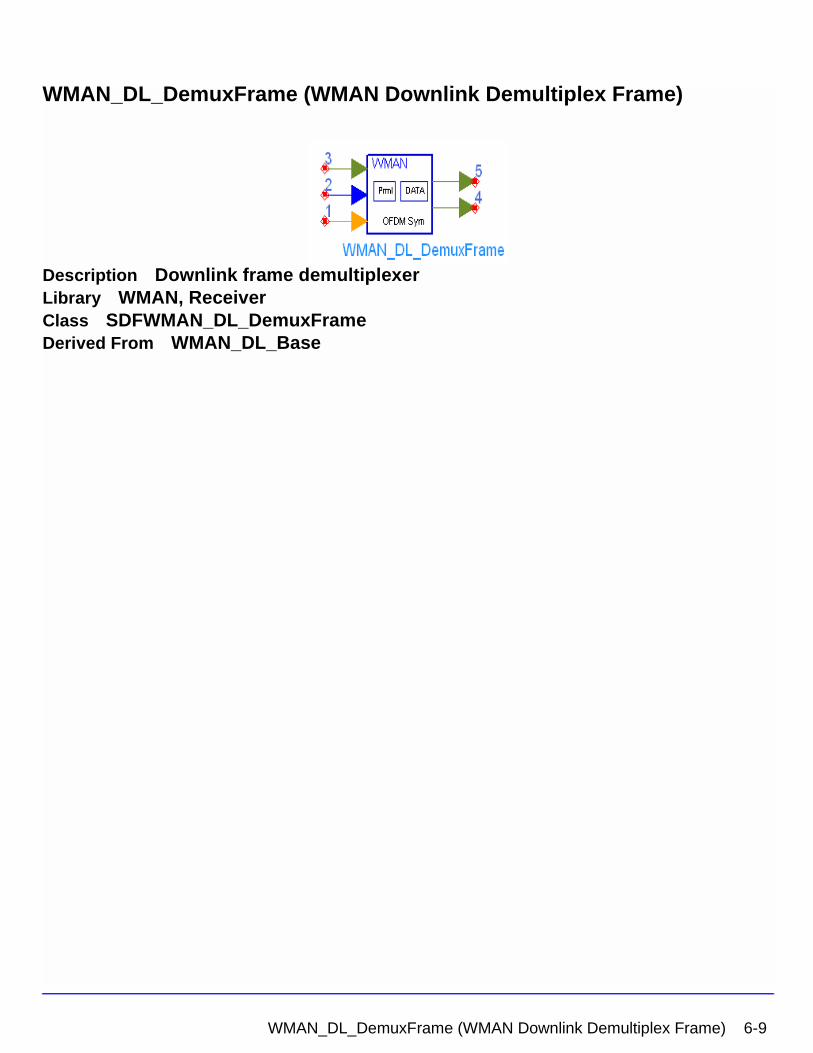
WMAN_DL_DemuxFrame (WMAN Downlink Demultiplex Frame)
Description Downlink frame demultiplexerLibrary WMAN, ReceiverClass SDFWMAN_DL_DemuxFrameDerived From WMAN_DL_Base
WMAN_DL_DemuxFrame (WMAN Downlink Demultiplex Frame) 6-9
WMAN Receiver Components
Parameters
Pin Inputs
Pin Outputs
Notes/Equations
1. This model is used to demultiplex downlink subframe into data symbol and preamble which is used for channel estimation. Idle interval and cyclic prefix are removed, and time and carrier frequency offsets are compensated before demultiplexing.
2. Each firing,
• tokens are consumed at pin Input,
where is the number of total samples of one downlink subframe.
Name Description Default Unit Type Range
NumberOfBurst Number of Burst 1 int [1, 16]
DataLength MAC PDU payload byte length of each burst
{100} int array [1, 16383]
Rate_ID Rate ID of each burst {1} int array [0, 6]
PreamblePresent Preamble present {0} int array {0, 1}
IdleInterval Idle interval 10 usec sec real [0, 1000]
Bandwidth Bandwidth 1.75 MHz Hz real (0, 1e9]
OversamplingOption Oversampling ratio option: Ratio 1, Ratio 2, Ratio 4, Ratio 8, Ratio 16, Ratio 32
Ratio 1 enum
CyclicPrefix Cyclic prefix 0.25 real [0, 1]
Pin Name Description Signal Type
1 index synchronization index int
2 DeltaF carrier frequency offset real
3 input input of downlink frame complex
Pin Name Description Signal Type
4 preamble output preamble for channel estimation complex
5 data output data sequence complex
SamplesFrame
SamplesFrame
6-10 WMAN_DL_DemuxFrame (WMAN Downlink Demultiplex Frame)
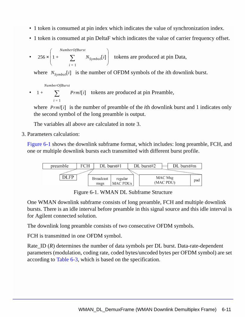
• 1 token is consumed at pin index which indicates the value of synchronization index.
• 1 token is consumed at pin DeltaF which indicates the value of carrier frequency offset.
• tokens are produced at pin Data,
where is the number of OFDM symbols of the ith downlink burst.
• tokens are produced at pin Preamble,
where is the number of preamble of the ith downlink burst and 1 indicates only the second symbol of the long preamble is output.
The variables all above are calculated in note 3.
3. Parameters calculation:
Figure 6-1 shows the downlink subframe format, which includes: long preamble, FCH, and one or multiple downlink bursts each transmitted with different burst profile.
Figure 6-1. WMAN DL Subframe Structure
One WMAN downlink subframe consists of long preamble, FCH and multiple downlink bursts. There is an idle interval before preamble in this signal source and this idle interval is for Agilent connected solution.
The downlink long preamble consists of two consecutive OFDM symbols.
FCH is transmitted in one OFDM symbol.
Rate_ID (R) determines the number of data symbols per DL burst. Data-rate-dependent parameters (modulation, coding rate, coded bytes/uncoded bytes per OFDM symbol) are set according to Table 6-3, which is based on the specification.
256 1 NSymbol i[ ]i 1=
NumberOfBurst
∑+
×
NSymbol i[ ]
1 Prml i[ ]i 1=
NumberOfBurst
∑+
Prml i[ ]
WMAN_DL_DemuxFrame (WMAN Downlink Demultiplex Frame) 6-11
WMAN Receiver Components
The number of OFDM symbols of the ith downlink burst ( ) is calculated as:
PreamblePresent indicates whether the downlink burst starts with a short preamble or not. Let represent the number of OFDM symbol per each preamble present. If PreamblePresent is set to 1 in the ith burst, then , otherwise,
So the total number of OFDM symbols for the downlink frame is calculated as:
The number of samples per one OFDM symbol ( ) is calculated as:
where G denotes the parameter CyclicPrefix.
Bandwidth determines the nominal channel bandwidth. The sampling frequency (Fs) implemented in the design is decided by Bandwidth, OversamplingOption and related sampling factor( ) as,
The sampling factors( ) are listed in Table 6-4.
Table 6-3. Data-Rate-Dependent Parameters
Rate_ID (R) ModulationUncoded block size (bytes)
Coded block size (bytes)
Overall coding rate RS code
CC code rate
0 BPSK 12 24 1/2 (12,12,0) 1/2
1 QPSK 24 48 1/2 (32,24,4) 2/3
2 QPSK 36 48 3/4 (40,36,2) 5/6
3 16-QAM 48 96 1/2 (64,48,8) 2/3
4 16-QAM 72 96 3/4 (80,72,4) 5/6
5 64-QAM 96 144 2/3 (108,96,6) 3/4
6 64-QAM 108 144 3/4 (120,108,6) 5/6
NSymbol i[ ]
NSymbol i[ ] ceil DataLength i[ ] 11+( ) uncodedBlockSize R i[ ][ ]( )⁄( )=
Prml i[ ]Prml i[ ] 1= Prml i[ ] 0=
NtotalSymbol
NtotalSymbol 2 1 NSymbol i[ ] Prml i[ ]+( )i 1=
NumberOfBurst
∑+ +=
SamplesOFDM
SamplesOFDM 2OversamplingOption
256× 1 G+( )×=
Nfactor
Fs floor Nfactor Bandwidth×( ) 8000⁄( ) 8000×=
Nfactor
6-12 WMAN_DL_DemuxFrame (WMAN Downlink Demultiplex Frame)
The samples of IdleInterval ( ) is calculated as:
So, the total samples of one downlink frame is
4. Output pin delay adjustment
Because of the transmission delay, a detected frame usually falls into 2 consecutive received blocks, so the buffer length for input Pin is . The start point of the
detected frame is determined by the input signal at pin index. Only after receiving the second input block, this model can output one actual subframe. So this model causes one subframe delay.
The DeltaF pin inputs the estimated frequency offset ( ) of each received frame.The ith
estimated frequency offset ( ) compensates for the phase in the current frame only.
Assume is the input signal from the input pin starting from
the first point of the frame, is the sequence, whose phase
caused by frequency offset is removed, then:
where
is frequency offset of the ith received frame which is the input at pin DeltaF,
is the sample time interval in WMAN system.
Table 6-4. Sampling Factor Requirement
sampling factor n bandwidth
8/7 For channel bandwidths that are a multiple of 1.75 MHz
86/75 else for channel bandwidths that are a multiple of 1.5 MHz
144/125 else for channel bandwidths that are a multiple of 1.25 MHz
316/275 else for channel bandwidths that are a multiple of 2.75 MHz
57/50 else for channel bandwidths that are a multiple of 2.0 MHz
8/7 else for channel bandwidths not otherwise specified
Samplesidle
Samplesidle IdleInterval 2OversamplingOption
Fs××=
SamplesFrame
SamplesFrame Samplesidle NtotalSymbol SamplesOFDM×+=
2 SamplesFrame×
fi∆
fi∆
x0 x1 … xSamplesFrame 1–, , ,
y0 y1 … ySamplesFrame 1–, , ,
yk xk ej2π∆fikTStep–
×=
fi∆
TStep1
Fs 2OversamplingOption×
---------------------------------------------------------=
WMAN_DL_DemuxFrame (WMAN Downlink Demultiplex Frame) 6-13
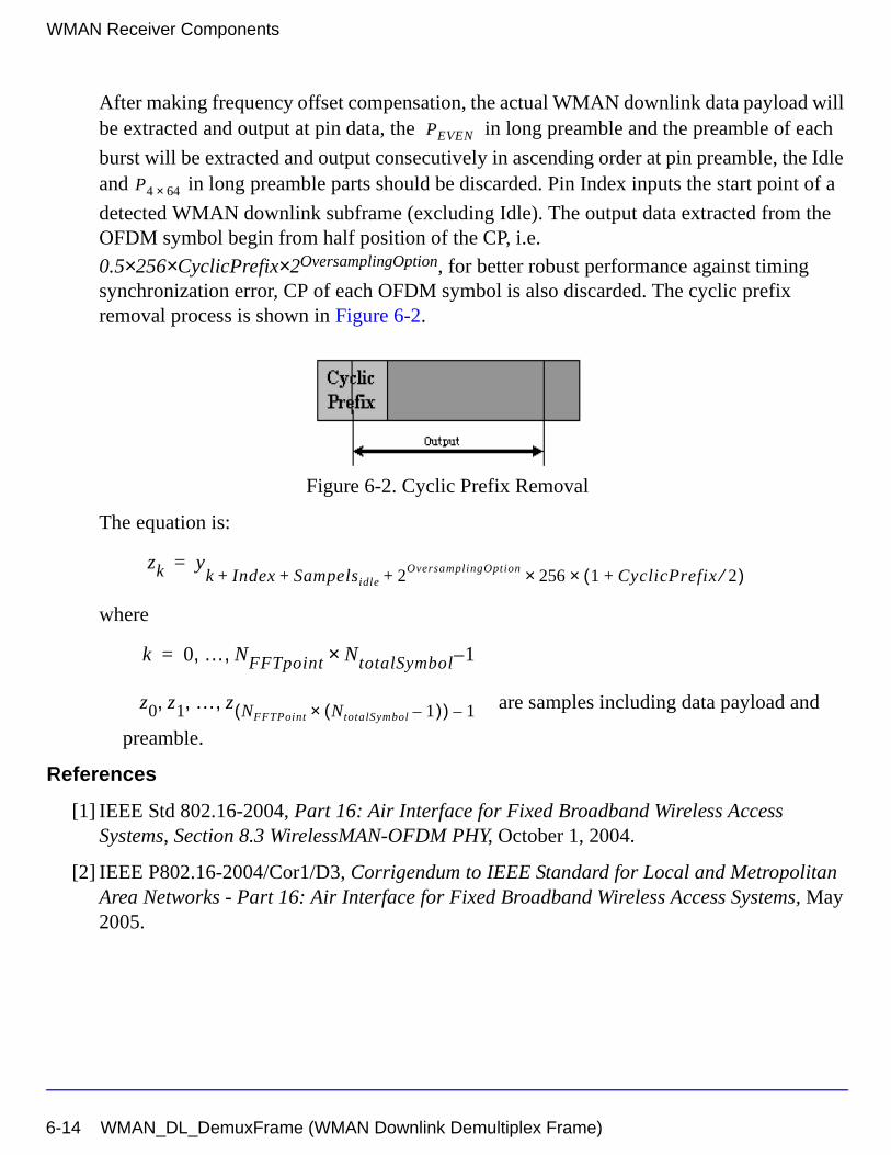
WMAN Receiver Components
After making frequency offset compensation, the actual WMAN downlink data payload will be extracted and output at pin data, the in long preamble and the preamble of each
burst will be extracted and output consecutively in ascending order at pin preamble, the Idle and in long preamble parts should be discarded. Pin Index inputs the start point of a
detected WMAN downlink subframe (excluding Idle). The output data extracted from the OFDM symbol begin from half position of the CP, i.e.
0.5×256×CyclicPrefix×2OversamplingOption, for better robust performance against timing synchronization error, CP of each OFDM symbol is also discarded. The cyclic prefix removal process is shown in Figure 6-2.
Figure 6-2. Cyclic Prefix Removal
The equation is:
where
are samples including data payload and
preamble.
References
[1] IEEE Std 802.16-2004, Part 16: Air Interface for Fixed Broadband Wireless Access Systems, Section 8.3 WirelessMAN-OFDM PHY, October 1, 2004.
[2] IEEE P802.16-2004/Cor1/D3, Corrigendum to IEEE Standard for Local and Metropolitan Area Networks - Part 16: Air Interface for Fixed Broadband Wireless Access Systems, May 2005.
PEVEN
P4 64×
zk yk Index Sampelsidle 2OversamplingOption 256× 1 CyclicPrefix 2⁄+( )×+ + +
=
k 0 … NFFTpoint NtotalSymbol× 1–, ,=
z0 z1 … z NFFTPoint NtotalSymbol 1–( )×( ) 1–, , ,
6-14 WMAN_DL_DemuxFrame (WMAN Downlink Demultiplex Frame)
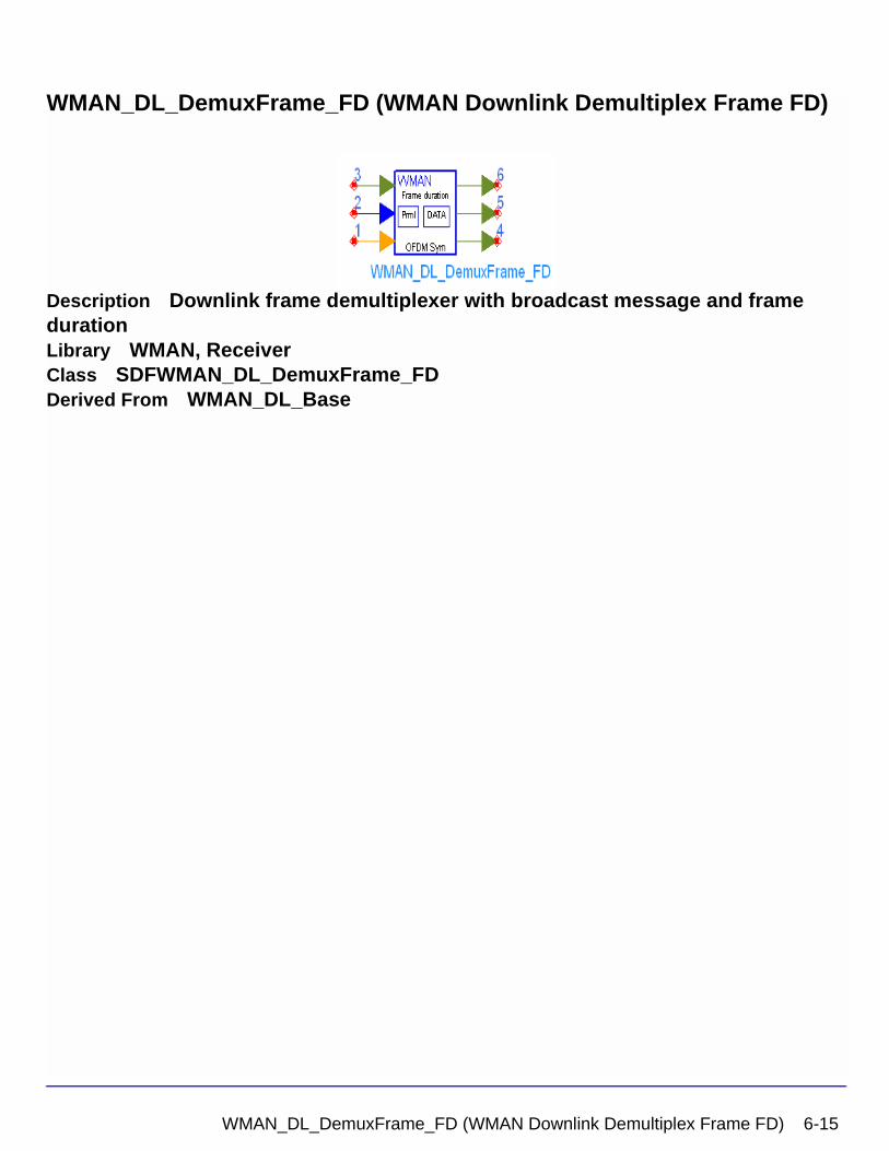
WMAN_DL_DemuxFrame_FD (WMAN Downlink Demultiplex Frame FD)
Description Downlink frame demultiplexer with broadcast message and frame durationLibrary WMAN, ReceiverClass SDFWMAN_DL_DemuxFrame_FDDerived From WMAN_DL_Base
WMAN_DL_DemuxFrame_FD (WMAN Downlink Demultiplex Frame FD) 6-15
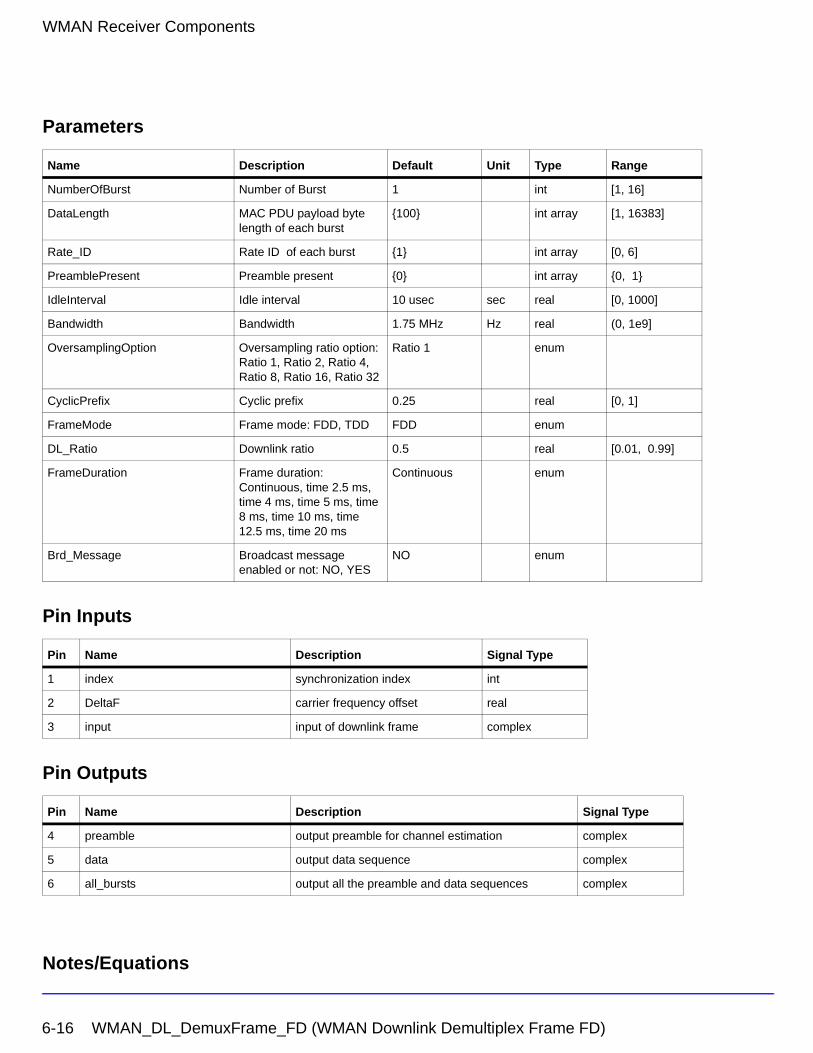
WMAN Receiver Components
Parameters
Pin Inputs
Pin Outputs
Notes/Equations
Name Description Default Unit Type Range
NumberOfBurst Number of Burst 1 int [1, 16]
DataLength MAC PDU payload byte length of each burst
{100} int array [1, 16383]
Rate_ID Rate ID of each burst {1} int array [0, 6]
PreamblePresent Preamble present {0} int array {0, 1}
IdleInterval Idle interval 10 usec sec real [0, 1000]
Bandwidth Bandwidth 1.75 MHz Hz real (0, 1e9]
OversamplingOption Oversampling ratio option: Ratio 1, Ratio 2, Ratio 4, Ratio 8, Ratio 16, Ratio 32
Ratio 1 enum
CyclicPrefix Cyclic prefix 0.25 real [0, 1]
FrameMode Frame mode: FDD, TDD FDD enum
DL_Ratio Downlink ratio 0.5 real [0.01, 0.99]
FrameDuration Frame duration: Continuous, time 2.5 ms, time 4 ms, time 5 ms, time 8 ms, time 10 ms, time 12.5 ms, time 20 ms
Continuous enum
Brd_Message Broadcast message enabled or not: NO, YES
NO enum
Pin Name Description Signal Type
1 index synchronization index int
2 DeltaF carrier frequency offset real
3 input input of downlink frame complex
Pin Name Description Signal Type
4 preamble output preamble for channel estimation complex
5 data output data sequence complex
6 all_bursts output all the preamble and data sequences complex
6-16 WMAN_DL_DemuxFrame_FD (WMAN Downlink Demultiplex Frame FD)
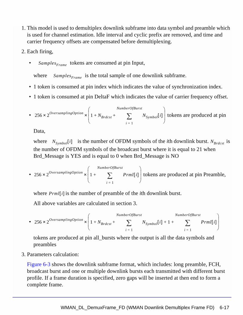
1. This model is used to demultiplex downlink subframe into data symbol and preamble which is used for channel estimation. Idle interval and cyclic prefix are removed, and time and carrier frequency offsets are compensated before demultiplexing.
2. Each firing,
• tokens are consumed at pin Input,
where is the total sample of one downlink subframe.
• 1 token is consumed at pin index which indicates the value of synchronization index.
• 1 token is consumed at pin DeltaF which indicates the value of carrier frequency offset.
• tokens are produced at pin
Data,
where is the number of OFDM symbols of the ith downlink burst. is
the number of OFDM symbols of the broadcast burst where it is equal to 21 when Brd_Message is YES and is equal to 0 when Brd_Message is NO
• tokens are produced at pin Preamble,
where is the number of preamble of the ith downlink burst.
All above variables are calculated in section 3.
•
tokens are produced at pin all_bursts where the output is all the data symbols and preambles
3. Parameters calculation:
Figure 6-3 shows the downlink subframe format, which includes: long preamble, FCH, broadcast burst and one or multiple downlink bursts each transmitted with different burst profile. If a frame duration is specified, zero gaps will be inserted at then end to form a complete frame.
SamplesFrame
SamplesFrame
256 2OversamplingOption× 1 NBrdcst NSymbol i[ ]
i 1=
NumberOfBurst
∑+ +
×
NSymbol i[ ] NBrdcst
256 2OversamplingOption× 1 Prml i[ ]
i 1=
NumberOfBurst
∑+
×
Prml i[ ]
256 2OversamplingOption× 1 NBrdcst NSymbol i[ ] 1 Prml i[ ]
i 1=
NumberOfBurst
∑+ +
i 1=
NumberOfBurst
∑+ +
×
WMAN_DL_DemuxFrame_FD (WMAN Downlink Demultiplex Frame FD) 6-17
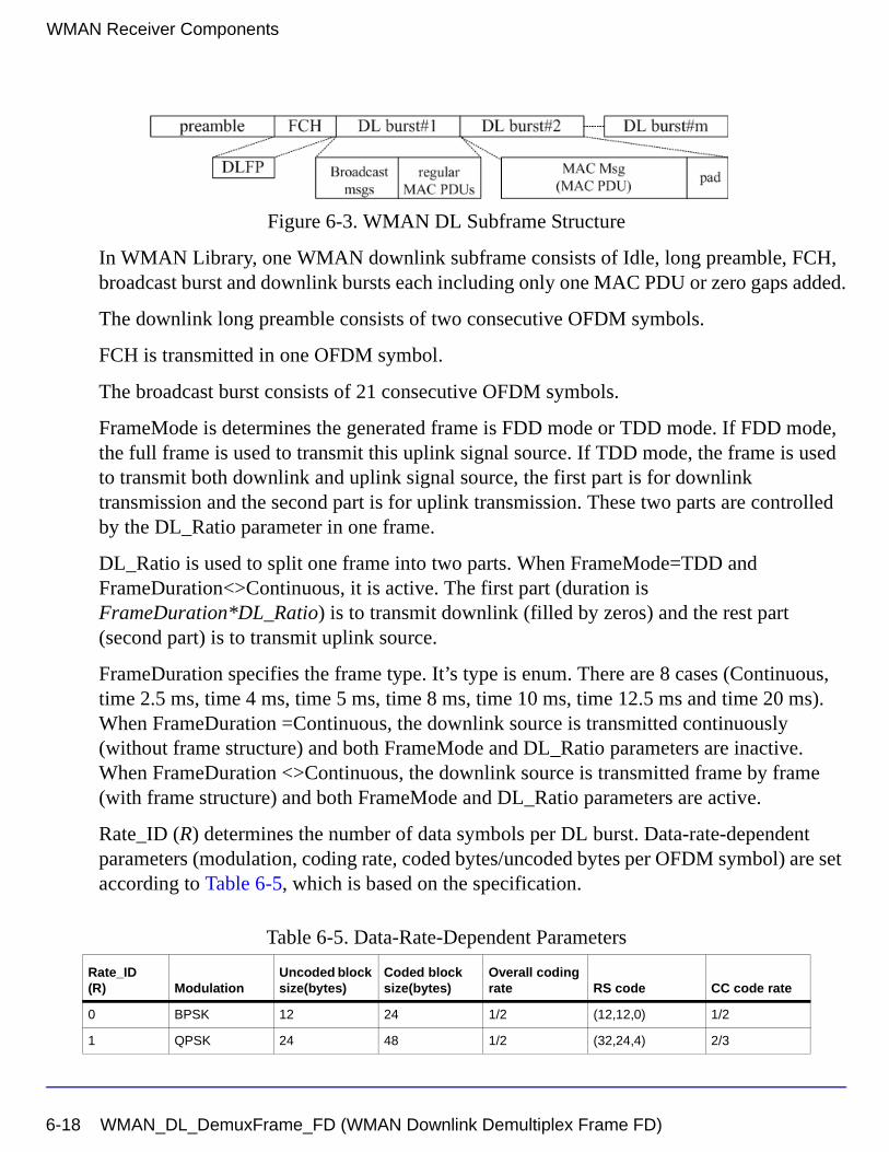
WMAN Receiver Components
Figure 6-3. WMAN DL Subframe Structure
In WMAN Library, one WMAN downlink subframe consists of Idle, long preamble, FCH, broadcast burst and downlink bursts each including only one MAC PDU or zero gaps added.
The downlink long preamble consists of two consecutive OFDM symbols.
FCH is transmitted in one OFDM symbol.
The broadcast burst consists of 21 consecutive OFDM symbols.
FrameMode is determines the generated frame is FDD mode or TDD mode. If FDD mode, the full frame is used to transmit this uplink signal source. If TDD mode, the frame is used to transmit both downlink and uplink signal source, the first part is for downlink transmission and the second part is for uplink transmission. These two parts are controlled by the DL_Ratio parameter in one frame.
DL_Ratio is used to split one frame into two parts. When FrameMode=TDD and FrameDuration<>Continuous, it is active. The first part (duration is FrameDuration*DL_Ratio) is to transmit downlink (filled by zeros) and the rest part (second part) is to transmit uplink source.
FrameDuration specifies the frame type. It’s type is enum. There are 8 cases (Continuous, time 2.5 ms, time 4 ms, time 5 ms, time 8 ms, time 10 ms, time 12.5 ms and time 20 ms). When FrameDuration =Continuous, the downlink source is transmitted continuously (without frame structure) and both FrameMode and DL_Ratio parameters are inactive. When FrameDuration <>Continuous, the downlink source is transmitted frame by frame (with frame structure) and both FrameMode and DL_Ratio parameters are active.
Rate_ID (R) determines the number of data symbols per DL burst. Data-rate-dependent parameters (modulation, coding rate, coded bytes/uncoded bytes per OFDM symbol) are set according to Table 6-5, which is based on the specification.
Table 6-5. Data-Rate-Dependent Parameters
Rate_ID(R) Modulation
Uncoded block size(bytes)
Coded block size(bytes)
Overall coding rate RS code CC code rate
0 BPSK 12 24 1/2 (12,12,0) 1/2
1 QPSK 24 48 1/2 (32,24,4) 2/3
6-18 WMAN_DL_DemuxFrame_FD (WMAN Downlink Demultiplex Frame FD)
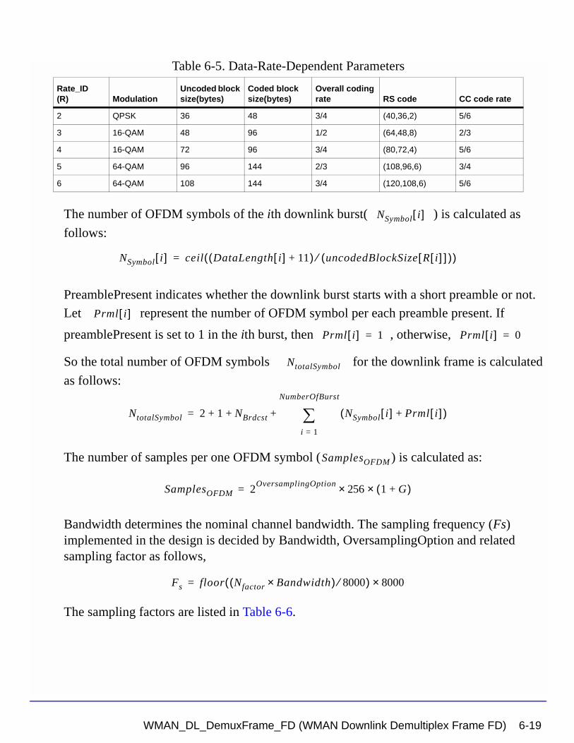
The number of OFDM symbols of the ith downlink burst( ) is calculated as
follows:
PreamblePresent indicates whether the downlink burst starts with a short preamble or not.
Let represent the number of OFDM symbol per each preamble present. If
preamblePresent is set to 1 in the ith burst, then , otherwise,
So the total number of OFDM symbols for the downlink frame is calculated
as follows:
The number of samples per one OFDM symbol ( ) is calculated as:
Bandwidth determines the nominal channel bandwidth. The sampling frequency (Fs) implemented in the design is decided by Bandwidth, OversamplingOption and related sampling factor as follows,
The sampling factors are listed in Table 6-6.
2 QPSK 36 48 3/4 (40,36,2) 5/6
3 16-QAM 48 96 1/2 (64,48,8) 2/3
4 16-QAM 72 96 3/4 (80,72,4) 5/6
5 64-QAM 96 144 2/3 (108,96,6) 3/4
6 64-QAM 108 144 3/4 (120,108,6) 5/6
Table 6-5. Data-Rate-Dependent Parameters
Rate_ID(R) Modulation
Uncoded block size(bytes)
Coded block size(bytes)
Overall coding rate RS code CC code rate
NSymbol i[ ]
NSymbol i[ ] ceil DataLength i[ ] 11+( ) uncodedBlockSize R i[ ][ ]( )⁄( )=
Prml i[ ]
Prml i[ ] 1= Prml i[ ] 0=
NtotalSymbol
NtotalSymbol 2 1 NBrdcst NSymbol i[ ] Prml i[ ]+( )i 1=
NumberOfBurst
∑+ + +=
SamplesOFDM
SamplesOFDM 2OversamplingOption
256× 1 G+( )×=
Fs floor Nfactor Bandwidth×( ) 8000⁄( ) 8000×=
WMAN_DL_DemuxFrame_FD (WMAN Downlink Demultiplex Frame FD) 6-19
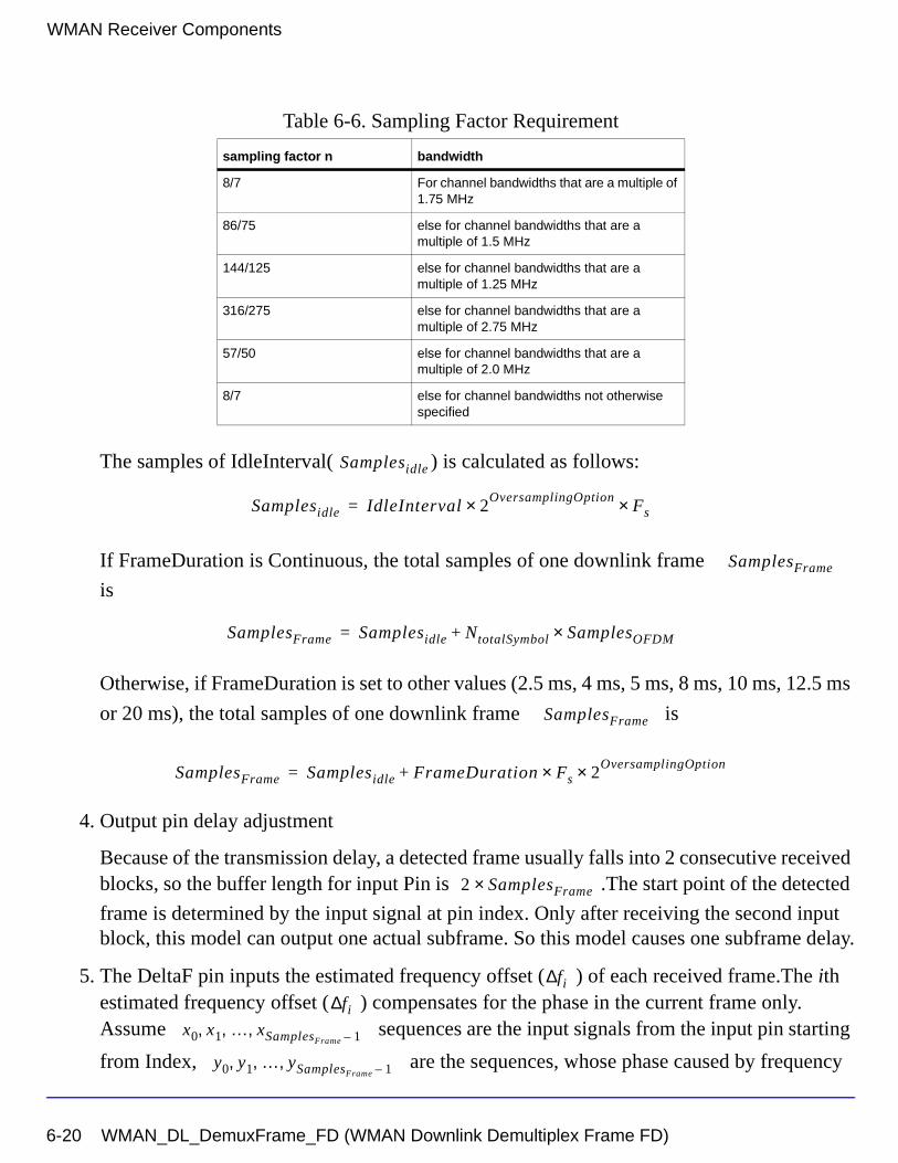
WMAN Receiver Components
The samples of IdleInterval( ) is calculated as follows:
If FrameDuration is Continuous, the total samples of one downlink frame
is
Otherwise, if FrameDuration is set to other values (2.5 ms, 4 ms, 5 ms, 8 ms, 10 ms, 12.5 ms
or 20 ms), the total samples of one downlink frame is
4. Output pin delay adjustment
Because of the transmission delay, a detected frame usually falls into 2 consecutive received blocks, so the buffer length for input Pin is .The start point of the detected
frame is determined by the input signal at pin index. Only after receiving the second input block, this model can output one actual subframe. So this model causes one subframe delay.
5. The DeltaF pin inputs the estimated frequency offset ( ) of each received frame.The ith estimated frequency offset ( ) compensates for the phase in the current frame only. Assume sequences are the input signals from the input pin starting
from Index, are the sequences, whose phase caused by frequency
Table 6-6. Sampling Factor Requirement
sampling factor n bandwidth
8/7 For channel bandwidths that are a multiple of 1.75 MHz
86/75 else for channel bandwidths that are a multiple of 1.5 MHz
144/125 else for channel bandwidths that are a multiple of 1.25 MHz
316/275 else for channel bandwidths that are a multiple of 2.75 MHz
57/50 else for channel bandwidths that are a multiple of 2.0 MHz
8/7 else for channel bandwidths not otherwise specified
Samplesidle
Samplesidle IdleInterval 2OversamplingOption
Fs××=
SamplesFrame
SamplesFrame Samplesidle NtotalSymbol SamplesOFDM×+=
SamplesFrame
SamplesFrame Samplesidle FrameDuration Fs 2× OversamplingOption×+=
2 SamplesFrame×
fi∆fi∆
x0 x1 … xSamplesFrame 1–, , ,
y0 y1 … ySamplesFrame 1–, , ,
6-20 WMAN_DL_DemuxFrame_FD (WMAN Downlink Demultiplex Frame FD)
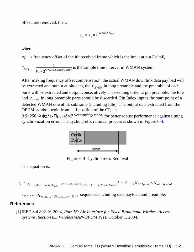
offset, are removed, then:
where
is frequency offset of the ith received frame which is the input at pin DeltaF,
is the sample time interval in WMAN system.
After making frequency offset compensation, the actual WMAN downlink data payload will be extracted and output at pin data, the in long preamble and the preamble of each
burst will be extracted and output consecutively in ascending order at pin preamble, the Idle and in long preamble parts should be discarded. Pin Index inputs the start point of a
detected WMAN downlink subframe (including Idle). The output data extracted from the OFDM symbol begin from half position of the CP, i.e. 0.5×256×ΧψχλιχΠρεφιξ× 2OversamplingOption, for better robust performance against timing synchronization error. The cyclic prefix removal process is shown in Figure 6-4.
Figure 6-4. Cyclic Prefix Removal
The equation is:
sequences including data payload and preamble.
References
[1] IEEE Std 802.16-2004, Part 16: Air Interface for Fixed Broadband Wireless Access Systems, Section 8.3 WirelessMAN-OFDM PHY, October 1, 2004.
yk xk ej2π∆fikTStep–
×=
fi∆
TStep1
Fs 2OversamplingOption×
---------------------------------------------------------=
PEVEN
P4 64×
zk yk Index Sampelsidle 2OversamplingOption 256× 1 cyclicPrefix 2⁄+( )×+ + +
k, 0 … NFFTpoint NtotalSymbol× 1–, ,= =
z0 z1 … z NFFTPoint NtotalSymbol 1–( )×( ) 1–, , ,
WMAN_DL_DemuxFrame_FD (WMAN Downlink Demultiplex Frame FD) 6-21
WMAN Receiver Components
[2] IEEE P802.16-2004/Cor1/D5, Corrigendum to IEEE Standard for Local and Metropolitan Area Networks - Part 16: Air Interface for Fixed Broadband Wireless Access Systems, Sept. 2005.
6-22 WMAN_DL_DemuxFrame_FD (WMAN Downlink Demultiplex Frame FD)
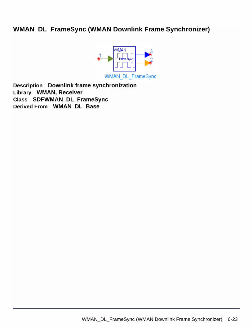
WMAN_DL_FrameSync (WMAN Downlink Frame Synchronizer)
Description Downlink frame synchronizationLibrary WMAN, ReceiverClass SDFWMAN_DL_FrameSyncDerived From WMAN_DL_Base
WMAN_DL_FrameSync (WMAN Downlink Frame Synchronizer) 6-23
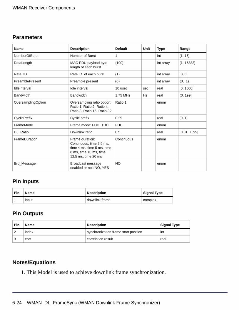
WMAN Receiver Components
Parameters
Pin Inputs
Pin Outputs
Notes/Equations
1. This Model is used to achieve downlink frame synchronization.
Name Description Default Unit Type Range
NumberOfBurst Number of Burst 1 int [1, 16]
DataLength MAC PDU payload byte length of each burst
{100} int array [1, 16383]
Rate_ID Rate ID of each burst {1} int array [0, 6]
PreamblePresent Preamble present {0} int array {0, 1}
IdleInterval Idle interval 10 usec sec real [0, 1000]
Bandwidth Bandwidth 1.75 MHz Hz real (0, 1e9]
OversamplingOption Oversampling ratio option: Ratio 1, Ratio 2, Ratio 4, Ratio 8, Ratio 16, Ratio 32
Ratio 1 enum
CyclicPrefix Cyclic prefix 0.25 real [0, 1]
FrameMode Frame mode: FDD, TDD FDD enum
DL_Ratio Downlink ratio 0.5 real [0.01, 0.99]
FrameDuration Frame duration: Continuous, time 2.5 ms, time 4 ms, time 5 ms, time 8 ms, time 10 ms, time 12.5 ms, time 20 ms
Continuous enum
Brd_Message Broadcast message enabled or not: NO, YES
NO enum
Pin Name Description Signal Type
1 input downlink frame complex
Pin Name Description Signal Type
2 index synchronization frame start position int
3 corr correlation result real
6-24 WMAN_DL_FrameSync (WMAN Downlink Frame Synchronizer)
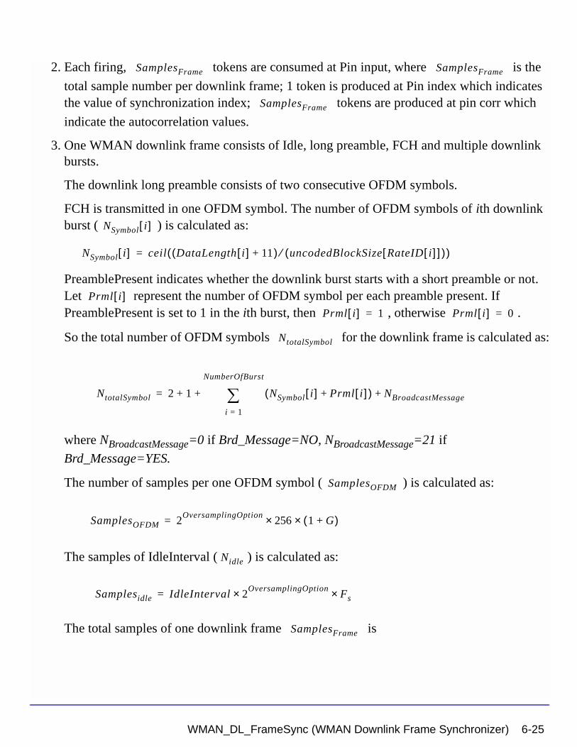
2. Each firing, tokens are consumed at Pin input, where is the
total sample number per downlink frame; 1 token is produced at Pin index which indicates the value of synchronization index; tokens are produced at pin corr which
indicate the autocorrelation values.
3. One WMAN downlink frame consists of Idle, long preamble, FCH and multiple downlink bursts.
The downlink long preamble consists of two consecutive OFDM symbols.
FCH is transmitted in one OFDM symbol. The number of OFDM symbols of ith downlink burst ( ) is calculated as:
PreamblePresent indicates whether the downlink burst starts with a short preamble or not. Let represent the number of OFDM symbol per each preamble present. If PreamblePresent is set to 1 in the ith burst, then , otherwise .
So the total number of OFDM symbols for the downlink frame is calculated as:
where NBroadcastMessage=0 if Brd_Message=NO, NBroadcastMessage=21 if
Brd_Message=YES.
The number of samples per one OFDM symbol ( ) is calculated as:
The samples of IdleInterval ( ) is calculated as:
The total samples of one downlink frame is
SamplesFrame SamplesFrame
SamplesFrame
NSymbol i[ ]
NSymbol i[ ] ceil DataLength i[ ] 11+( ) uncodedBlockSize RateID i[ ][ ]( )⁄( )=
Prml i[ ]Prml i[ ] 1= Prml i[ ] 0=
NtotalSymbol
NtotalSymbol 2 1 NSymbol i[ ] Prml i[ ]+( ) NBroadcastMessage+
i 1=
NumberOfBurst
∑+ +=
SamplesOFDM
SamplesOFDM 2OversamplingOption
256× 1 G+( )×=
Nidle
Samplesidle IdleInterval 2OversamplingOption
Fs××=
SamplesFrame
WMAN_DL_FrameSync (WMAN Downlink Frame Synchronizer) 6-25
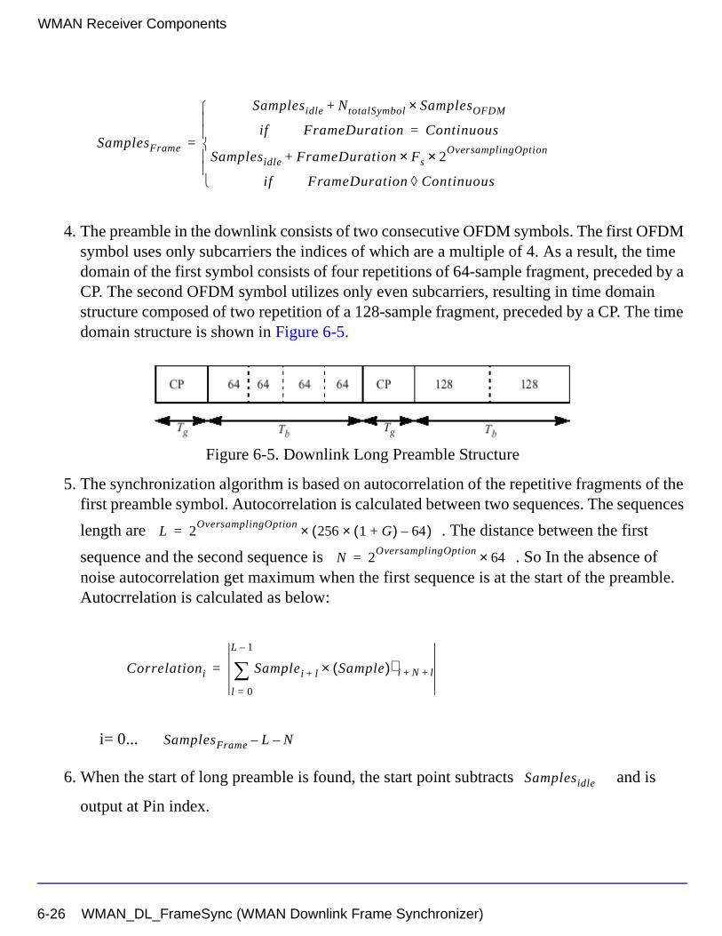
WMAN Receiver Components
4. The preamble in the downlink consists of two consecutive OFDM symbols. The first OFDM symbol uses only subcarriers the indices of which are a multiple of 4. As a result, the time domain of the first symbol consists of four repetitions of 64-sample fragment, preceded by a CP. The second OFDM symbol utilizes only even subcarriers, resulting in time domain structure composed of two repetition of a 128-sample fragment, preceded by a CP. The time domain structure is shown in Figure 6-5.
Figure 6-5. Downlink Long Preamble Structure
5. The synchronization algorithm is based on autocorrelation of the repetitive fragments of the first preamble symbol. Autocorrelation is calculated between two sequences. The sequences
length are . The distance between the first
sequence and the second sequence is . So In the absence of noise autocorrelation get maximum when the first sequence is at the start of the preamble. Autocrrelation is calculated as below:
i= 0...
6. When the start of long preamble is found, the start point subtracts and is
output at Pin index.
SamplesFrame
Samplesidle NtotalSymbol SamplesOFDM×+
if FrameDuration Continuous=
Samplesidle FrameDuration Fs× 2OversamplingOption×+
if FrameDuration Continuous◊
=
L 2OversamplingOption
256 1 G+( )× 64–( )×=
N 2OversamplingOption
64×=
Correlationi Samplei l+ Sample( )∗ i N l+ +×l 0=
L 1–
∑=
SamplesFrame L– N–
Samplesidle
6-26 WMAN_DL_FrameSync (WMAN Downlink Frame Synchronizer)
References
[1] IEEE Std 802.16-2004, Part 16: Air Interface for Fixed Broadband Wireless Access Systems, Section 8.3 WirelessMAN-OFDM PHY, October 1, 2004.
[2] IEEE P802.16-2004/Cor1/D3, Corrigendum to IEEE Standard for Local and Metropolitan Area Networks - Part 16: Air Interface for Fixed Broadband Wireless Access Systems, May 2005.
WMAN_DL_FrameSync (WMAN Downlink Frame Synchronizer) 6-27
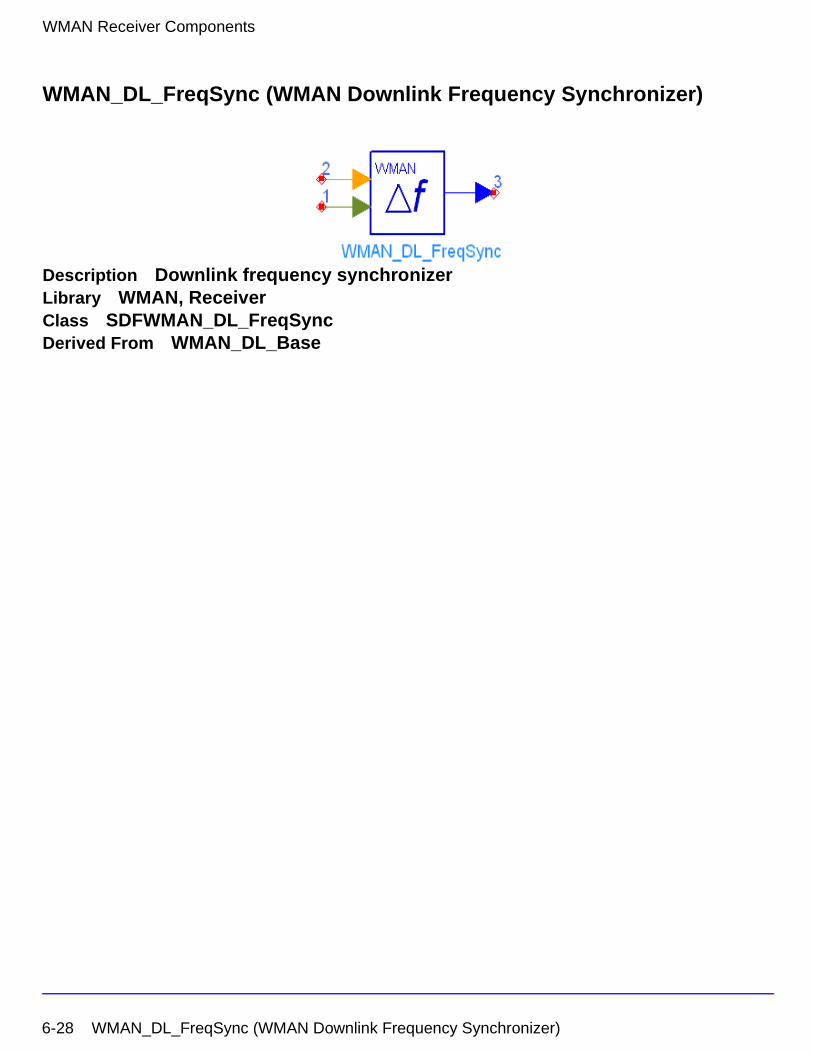
WMAN Receiver Components
WMAN_DL_FreqSync (WMAN Downlink Frequency Synchronizer)
Description Downlink frequency synchronizerLibrary WMAN, ReceiverClass SDFWMAN_DL_FreqSyncDerived From WMAN_DL_Base
6-28 WMAN_DL_FreqSync (WMAN Downlink Frequency Synchronizer)
Parameters
Pin Inputs
Pin Outputs
Notes/Equations
1. This Model is used to achieve downlink frequency synchronization.
Name Description Default Unit Type Range
NumberOfBurst Number of Burst 1 int [1, 16]
DataLength MAC PDU payload byte length of each burst
{100} int array [1, 16383]
Rate_ID Rate ID of each burst {1} int array [0, 6]
PreamblePresent Preamble present {0} int array {0, 1}
IdleInterval Idle interval 10 usec sec real [0, 1000]
Bandwidth Bandwidth 1.75 MHz Hz real (0, 1e9]
OversamplingOption Oversampling ratio option: Ratio 1, Ratio 2, Ratio 4, Ratio 8, Ratio 16, Ratio 32
Ratio 1 enum
CyclicPrefix Cyclic prefix 0.25 real [0, 1]
FrameMode Frame mode: FDD, TDD FDD enum
DL_Ratio Downlink ratio 0.5 real [0.01, 0.99]
FrameDuration Frame duration: Continuous, time 2.5 ms, time 4 ms, time 5 ms, time 8 ms, time 10 ms, time 12.5 ms, time 20 ms
Continuous enum
Brd_Message Broadcast message enabled or not: NO, YES
NO enum
Pin Name Description Signal Type
1 input downlink frame complex
2 index downlink frame start index int
Pin Name Description Signal Type
3 DeltaF frequency offset real
WMAN_DL_FreqSync (WMAN Downlink Frequency Synchronizer) 6-29
WMAN Receiver Components
2. Each firing, tokens are consumed at Pin input, where is the
total sample per downlink frame; 1 token is consumed at Pin index which indicates the value of synchronization index; 1 token is produced at Pin DeltaF which indicates the value of frequency offset.
3. One WMAN downlink frame consists of Idle, long preamble, FCH and multiple downlink bursts.
The downlink long preamble consists of two consecutive OFDM symbols.
FCH is transmitted in one OFDM symbol. The number of OFDM symbols of ith downlink burst( ) is calculated as:
PreamblePresent indicates whether the downlink burst starts with a short preamble or not. Let represent the number of OFDM symbol per each preamble present. If PreamblePresent is set to 1 in the ith burst, then , otherwise .
So the total number of OFDM symbols for the downlink frame is calculated as:
where NBroadcastMessage=0 if Brd_Message=NO, NBroadcastMessage=21 if
Brd_Message=YES.
The number of samples per one OFDM symbol ( ) is calculated as:
The samples of IdleInterval( ) is calculated as:
So the total samples of one downlink frame is
SamplesFrame SamplesFrame
NSymbol i[ ]
NSymbol i[ ] ceil DataLength i[ ] 11+( ) uncodedBlockSize RateID i[ ][ ]( )⁄( )=
Prml i[ ]Prml i[ ] 1= Prml i[ ] 0=
NtotalSymbol
NtotalSymbol 2 1 NSymbol i[ ] Prml i[ ]+( ) NBroadcastMessage+
i 1=
NumberOfBurst
∑+ +=
SamplesOFDM
SamplesOFDM 2OversamplingOption
256× 1 G+( )×=
Nidle
Samplesidle IdleInterval 2OversamplingOption
Fs××=
SamplesFrame
6-30 WMAN_DL_FreqSync (WMAN Downlink Frequency Synchronizer)
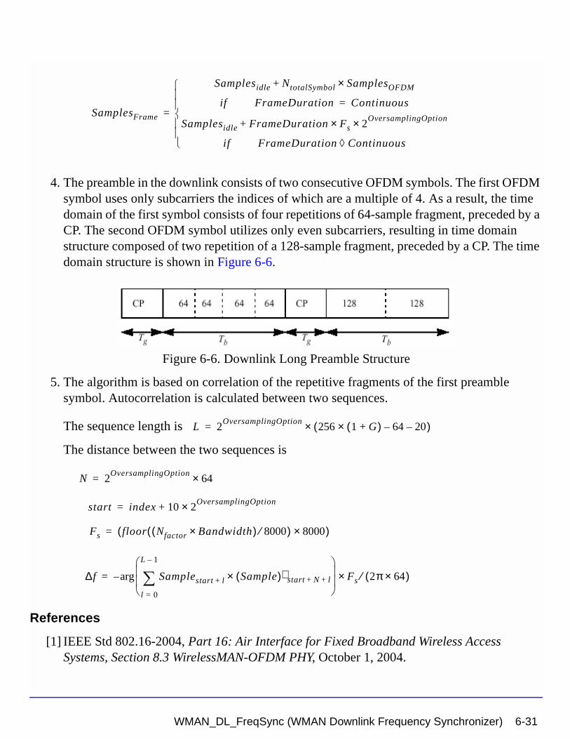
4. The preamble in the downlink consists of two consecutive OFDM symbols. The first OFDM symbol uses only subcarriers the indices of which are a multiple of 4. As a result, the time domain of the first symbol consists of four repetitions of 64-sample fragment, preceded by a CP. The second OFDM symbol utilizes only even subcarriers, resulting in time domain structure composed of two repetition of a 128-sample fragment, preceded by a CP. The time domain structure is shown in Figure 6-6.
Figure 6-6. Downlink Long Preamble Structure
5. The algorithm is based on correlation of the repetitive fragments of the first preamble symbol. Autocorrelation is calculated between two sequences.
The sequence length is
The distance between the two sequences is
References
[1] IEEE Std 802.16-2004, Part 16: Air Interface for Fixed Broadband Wireless Access Systems, Section 8.3 WirelessMAN-OFDM PHY, October 1, 2004.
SamplesFrame
Samplesidle NtotalSymbol SamplesOFDM×+
if FrameDuration Continuous=
Samplesidle FrameDuration Fs× 2OversamplingOption×+
if FrameDuration Continuous◊
=
L 2OversamplingOption
256 1 G+( )× 64– 20–( )×=
N 2OversamplingOption
64×=
start index 10 2OversamplingOption×+=
Fs floor Nfactor Bandwidth×( ) 8000⁄( ) 8000×( )=
∆f Samplestart l+ Sample( )∗ start N l+ +×l 0=
L 1–
∑
Fs× 2π 64×( )⁄arg–=
WMAN_DL_FreqSync (WMAN Downlink Frequency Synchronizer) 6-31

WMAN Receiver Components
[2] IEEE P802.16-2004/Cor1/D3, Corrigendum to IEEE Standard for Local and Metropolitan Area Networks - Part 16: Air Interface for Fixed Broadband Wireless Access Systems, May 2005.
6-32 WMAN_DL_FreqSync (WMAN Downlink Frequency Synchronizer)
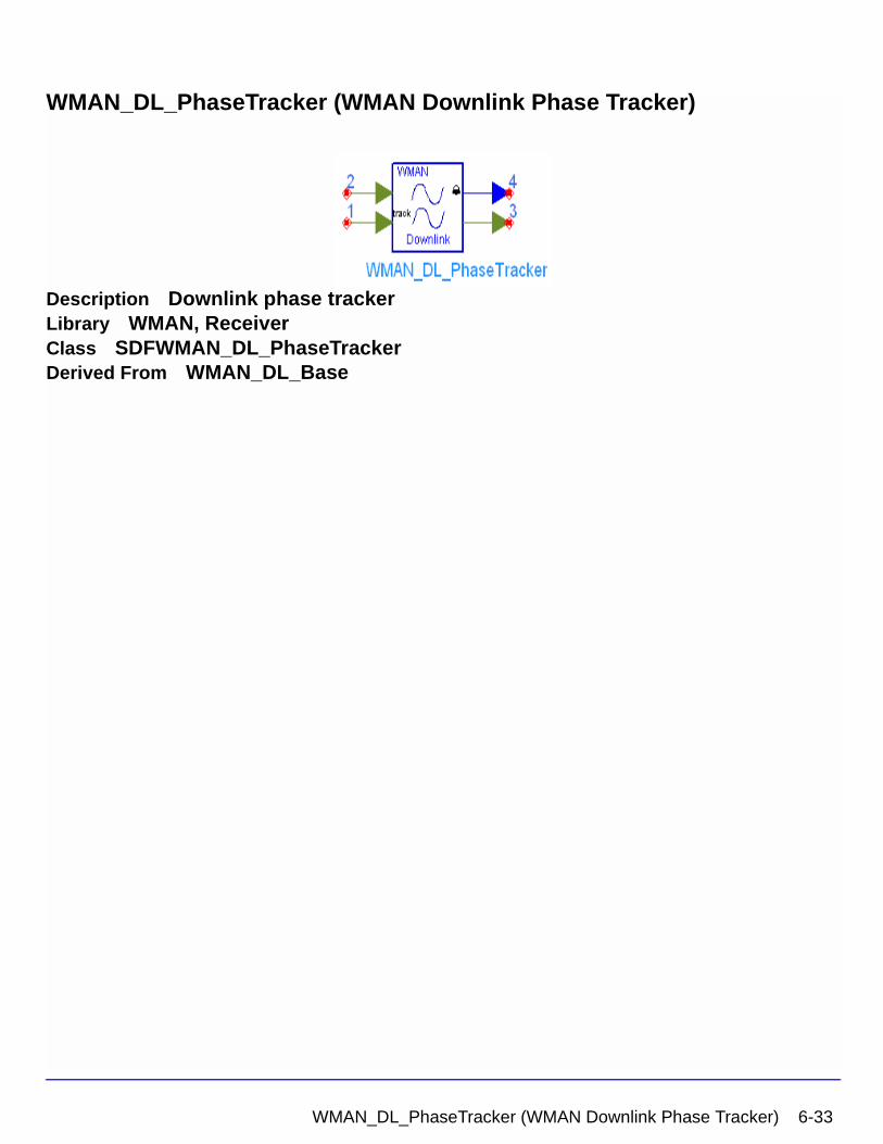
WMAN_DL_PhaseTracker (WMAN Downlink Phase Tracker)
Description Downlink phase trackerLibrary WMAN, ReceiverClass SDFWMAN_DL_PhaseTrackerDerived From WMAN_DL_Base
WMAN_DL_PhaseTracker (WMAN Downlink Phase Tracker) 6-33
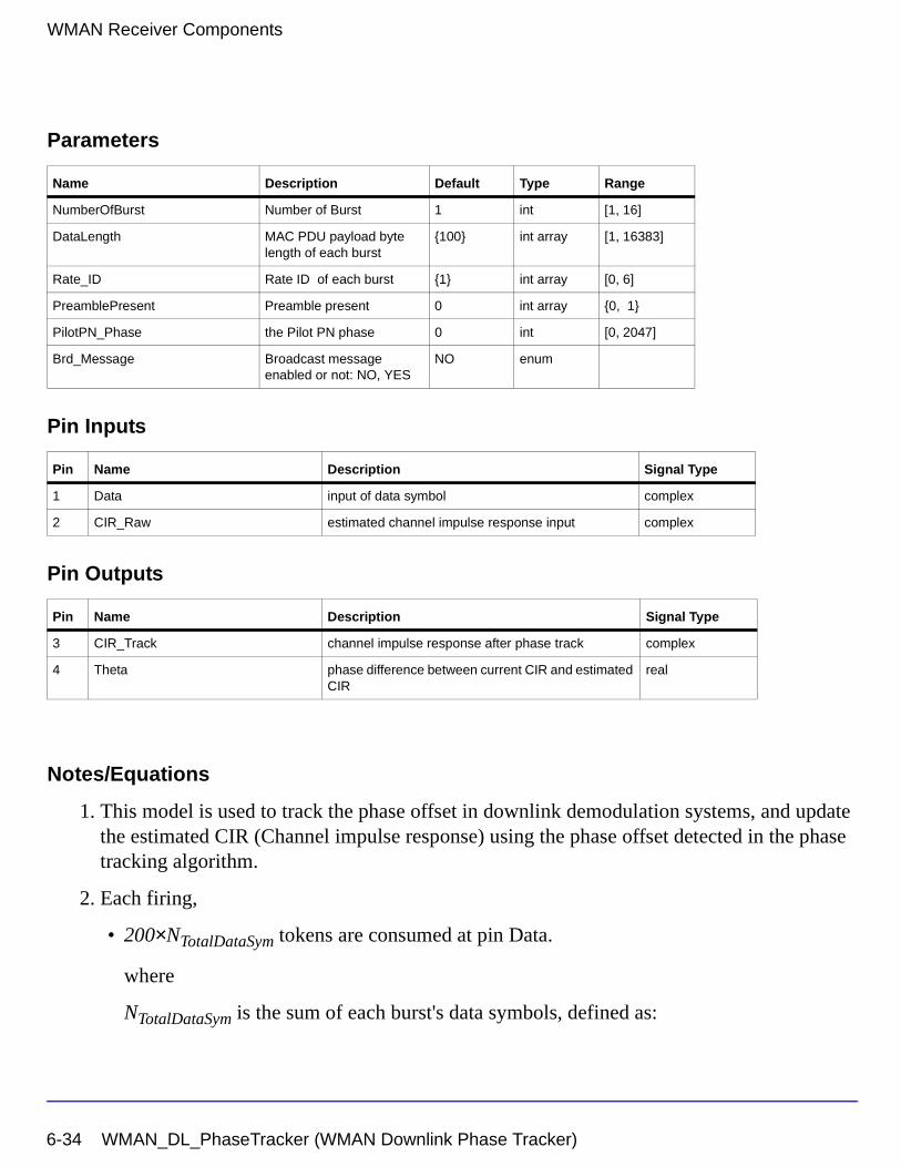
WMAN Receiver Components
Parameters
Pin Inputs
Pin Outputs
Notes/Equations
1. This model is used to track the phase offset in downlink demodulation systems, and update the estimated CIR (Channel impulse response) using the phase offset detected in the phase tracking algorithm.
2. Each firing,
• 200×NTotalDataSym tokens are consumed at pin Data.
where
NTotalDataSym is the sum of each burst's data symbols, defined as:
Name Description Default Type Range
NumberOfBurst Number of Burst 1 int [1, 16]
DataLength MAC PDU payload byte length of each burst
{100} int array [1, 16383]
Rate_ID Rate ID of each burst {1} int array [0, 6]
PreamblePresent Preamble present 0 int array {0, 1}
PilotPN_Phase the Pilot PN phase 0 int [0, 2047]
Brd_Message Broadcast message enabled or not: NO, YES
NO enum
Pin Name Description Signal Type
1 Data input of data symbol complex
2 CIR_Raw estimated channel impulse response input complex
Pin Name Description Signal Type
3 CIR_Track channel impulse response after phase track complex
4 Theta phase difference between current CIR and estimated CIR
real
6-34 WMAN_DL_PhaseTracker (WMAN Downlink Phase Tracker)
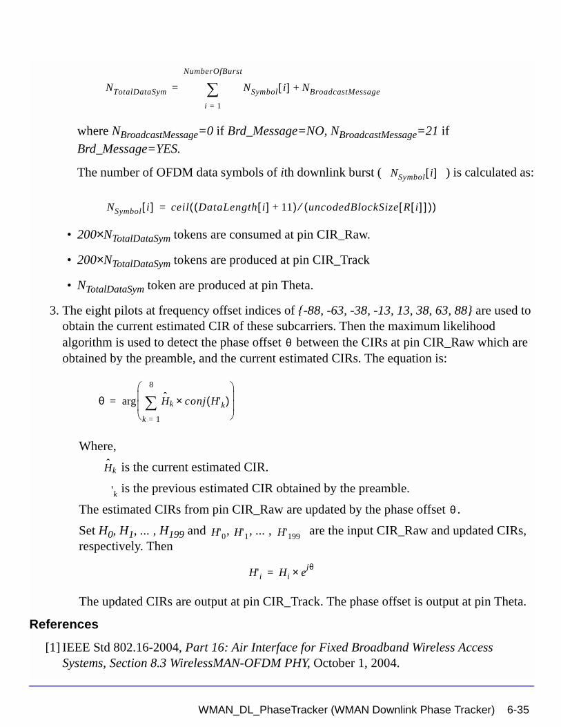
where NBroadcastMessage=0 if Brd_Message=NO, NBroadcastMessage=21 if
Brd_Message=YES.
The number of OFDM data symbols of ith downlink burst ( ) is calculated as:
• 200×NTotalDataSym tokens are consumed at pin CIR_Raw.
• 200×NTotalDataSym tokens are produced at pin CIR_Track
• NTotalDataSym token are produced at pin Theta.
3. The eight pilots at frequency offset indices of {-88, -63, -38, -13, 13, 38, 63, 88} are used to obtain the current estimated CIR of these subcarriers. Then the maximum likelihood algorithm is used to detect the phase offset between the CIRs at pin CIR_Raw which are obtained by the preamble, and the current estimated CIRs. The equation is:
Where,
is the current estimated CIR.
is the previous estimated CIR obtained by the preamble.
The estimated CIRs from pin CIR_Raw are updated by the phase offset .
Set H0, H1, ... , H199 and , , ... , are the input CIR_Raw and updated CIRs, respectively. Then
The updated CIRs are output at pin CIR_Track. The phase offset is output at pin Theta.
References
[1] IEEE Std 802.16-2004, Part 16: Air Interface for Fixed Broadband Wireless Access Systems, Section 8.3 WirelessMAN-OFDM PHY, October 1, 2004.
NTotalDataSym NSymbol i[ ] NBroadcastMessage+
i 1=
NumberOfBurst
∑=
NSymbol i[ ]
NSymbol i[ ] ceil DataLength i[ ] 11+( ) uncodedBlockSize R i[ ][ ]( )⁄( )=
θ
θ Hk conj H'k( )×k 1=
8
∑
arg=
Hk
'k
θ
H'0 H'1 H'199
H'i Hi ejθ×=
WMAN_DL_PhaseTracker (WMAN Downlink Phase Tracker) 6-35
WMAN Receiver Components
[2] IEEE P802.16-2004/Cor1/D3, Corrigendum to IEEE Standard for Local and Metropolitan Area Networks - Part 16: Air Interface for Fixed Broadband Wireless Access Systems, May 2005.
6-36 WMAN_DL_PhaseTracker (WMAN Downlink Phase Tracker)
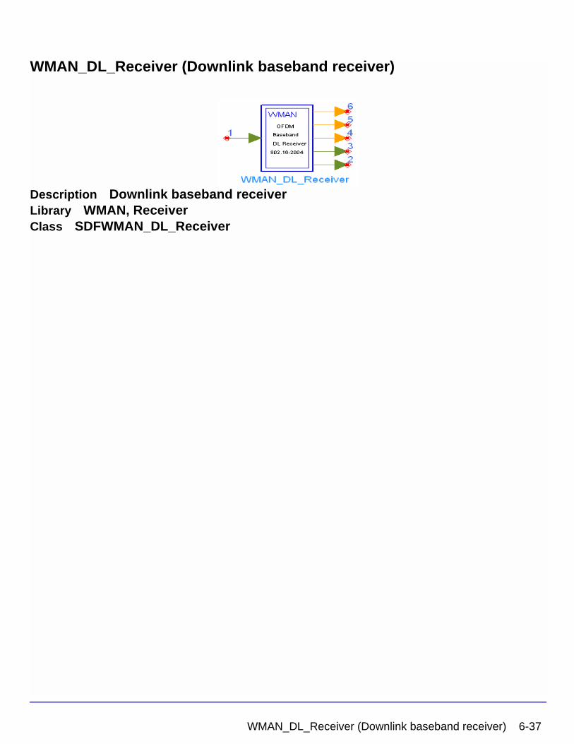
WMAN_DL_Receiver (Downlink baseband receiver)
Description Downlink baseband receiverLibrary WMAN, ReceiverClass SDFWMAN_DL_Receiver
WMAN_DL_Receiver (Downlink baseband receiver) 6-37
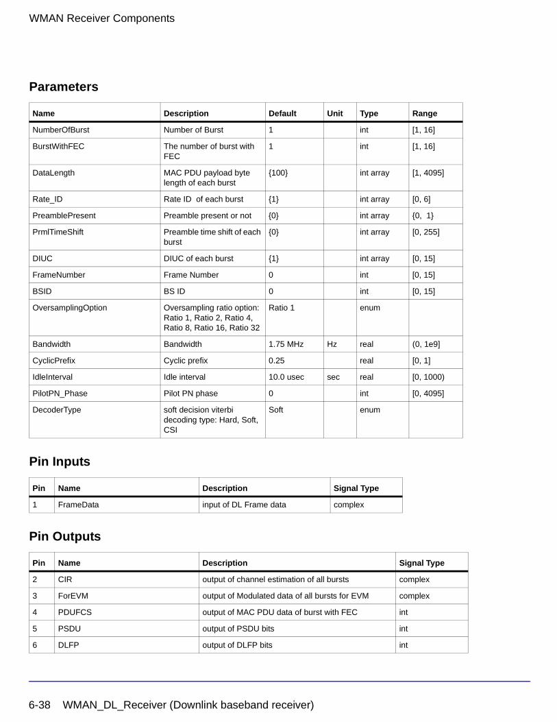
WMAN Receiver Components
Parameters
Pin Inputs
Pin Outputs
Name Description Default Unit Type Range
NumberOfBurst Number of Burst 1 int [1, 16]
BurstWithFEC The number of burst with FEC
1 int [1, 16]
DataLength MAC PDU payload byte length of each burst
{100} int array [1, 4095]
Rate_ID Rate ID of each burst {1} int array [0, 6]
PreamblePresent Preamble present or not {0} int array {0, 1}
PrmlTimeShift Preamble time shift of each burst
{0} int array [0, 255]
DIUC DIUC of each burst {1} int array [0, 15]
FrameNumber Frame Number 0 int [0, 15]
BSID BS ID 0 int [0, 15]
OversamplingOption Oversampling ratio option: Ratio 1, Ratio 2, Ratio 4, Ratio 8, Ratio 16, Ratio 32
Ratio 1 enum
Bandwidth Bandwidth 1.75 MHz Hz real (0, 1e9]
CyclicPrefix Cyclic prefix 0.25 real [0, 1]
IdleInterval Idle interval 10.0 usec sec real [0, 1000)
PilotPN_Phase Pilot PN phase 0 int [0, 4095]
DecoderType soft decision viterbi decoding type: Hard, Soft, CSI
Soft enum
Pin Name Description Signal Type
1 FrameData input of DL Frame data complex
Pin Name Description Signal Type
2 CIR output of channel estimation of all bursts complex
3 ForEVM output of Modulated data of all bursts for EVM complex
4 PDUFCS output of MAC PDU data of burst with FEC int
5 PSDU output of PSDU bits int
6 DLFP output of DLFP bits int
6-38 WMAN_DL_Receiver (Downlink baseband receiver)
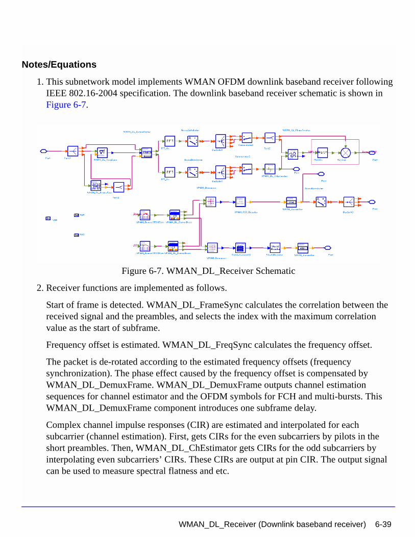
Notes/Equations
1. This subnetwork model implements WMAN OFDM downlink baseband receiver following IEEE 802.16-2004 specification. The downlink baseband receiver schematic is shown in Figure 6-7.
Figure 6-7. WMAN_DL_Receiver Schematic
2. Receiver functions are implemented as follows.
Start of frame is detected. WMAN_DL_FrameSync calculates the correlation between the received signal and the preambles, and selects the index with the maximum correlation value as the start of subframe.
Frequency offset is estimated. WMAN_DL_FreqSync calculates the frequency offset.
The packet is de-rotated according to the estimated frequency offsets (frequency synchronization). The phase effect caused by the frequency offset is compensated by WMAN_DL_DemuxFrame. WMAN_DL_DemuxFrame outputs channel estimation sequences for channel estimator and the OFDM symbols for FCH and multi-bursts. This WMAN_DL_DemuxFrame component introduces one subframe delay.
Complex channel impulse responses (CIR) are estimated and interpolated for each subcarrier (channel estimation). First, gets CIRs for the even subcarriers by pilots in the short preambles. Then, WMAN_DL_ChEstimator gets CIRs for the odd subcarriers by interpolating even subcarriers’ CIRs. These CIRs are output at pin CIR. The output signal can be used to measure spectral flatness and etc.
WMAN_DL_Receiver (Downlink baseband receiver) 6-39
WMAN Receiver Components
Each OFDM symbol is transformed into 200 subcarriers by FFT. Phase of the pilot subcarriers are estimated, then all subcarrier values are de-rotated according to the estimated phase. WMAN_DL_PhaseTracker implements these functions.
Each subcarrier value is divided by a complex estimated channel response coefficient (phase tracking, phase synchronization, and equalization). This simple one-tap frequency domain channel response compensation is implemented in the receiver.
After equalization, the demodulated OFDM symbols for FCH and multi-bursts are output at pin For_EVM. The signal can be used to show the demodulated constellation and to calculate the RCE (relative constellation error) or EVM.
WMAN_DemuxOFDMSym de-multiplexes 200 subcarriers into 192 data subcarriers and 8 pilot subcarriers. WMAN_DemuxOFDMSym just outputs signal at 192 data subcarriers.
The burst with FEC-encoded is separated from the multi-bursts in WMAN_DL_DemuxBurst.
The demodulated OFDM symbols of burst with FEC are then de-mapped by WMAN_Demapper. Three demapper types (CSI, Soft and Hard) are supported in WMAN_Demaper.
After FEC decoding, de-interleaving, de-scrambling, the MAC PDU data are achieved, which are divided into MAC header, MAC PDU payloads and CRC. The MAC PDU and its payloads are output at pin PDUFCS and PSDU respectively.
The demodulated FCH OFDM symbol is also de-mapped by WMAN_Demapper. After FEC decoding, de-interleaving, de-scrambling, the decoded DLFP is output at pin DLFP.
3. Parameter Details
• NumberOfBurst specifies the number of active downlink bursts.
• BurstWithFEC specifies the downlink burst with FEC.
• DataLength is the array of each DL burst's MAC PDU payload byte length. Rate_ID is the array of each DL burst's Rate ID, whose range is from 0 to 6. DataLength and Rate_ID (R) determine the number of data symbols per DL burst. Data-rate-dependent parameters (modulation, coding rate, coded bytes/uncoded bytes per OFDM symbol) are set according to Table 6-7, which is based on the specification.
6-40 WMAN_DL_Receiver (Downlink baseband receiver)
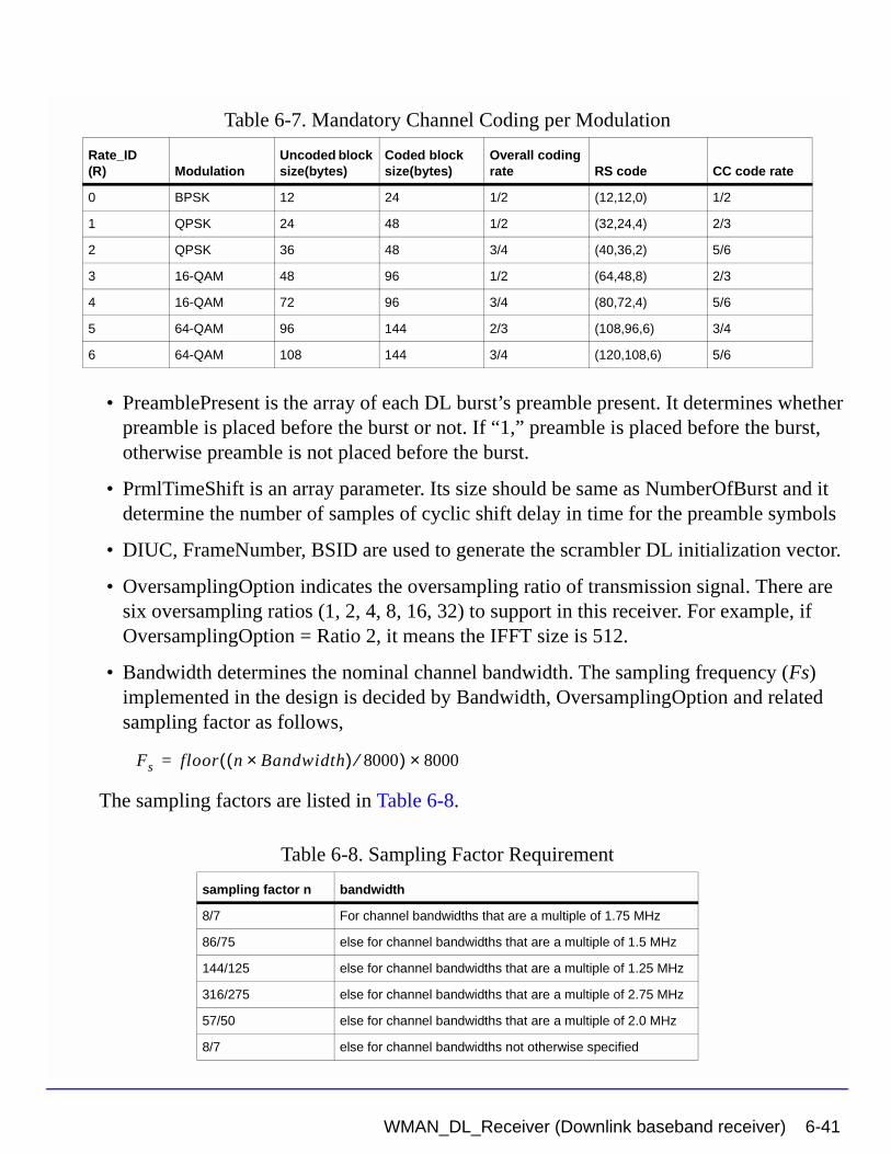
• PreamblePresent is the array of each DL burst’s preamble present. It determines whether preamble is placed before the burst or not. If “1,” preamble is placed before the burst, otherwise preamble is not placed before the burst.
• PrmlTimeShift is an array parameter. Its size should be same as NumberOfBurst and it determine the number of samples of cyclic shift delay in time for the preamble symbols
• DIUC, FrameNumber, BSID are used to generate the scrambler DL initialization vector.
• OversamplingOption indicates the oversampling ratio of transmission signal. There are six oversampling ratios (1, 2, 4, 8, 16, 32) to support in this receiver. For example, if OversamplingOption = Ratio 2, it means the IFFT size is 512.
• Bandwidth determines the nominal channel bandwidth. The sampling frequency (Fs) implemented in the design is decided by Bandwidth, OversamplingOption and related sampling factor as follows,
The sampling factors are listed in Table 6-8.
Table 6-7. Mandatory Channel Coding per Modulation
Rate_ID(R) Modulation
Uncoded block size(bytes)
Coded block size(bytes)
Overall coding rate RS code CC code rate
0 BPSK 12 24 1/2 (12,12,0) 1/2
1 QPSK 24 48 1/2 (32,24,4) 2/3
2 QPSK 36 48 3/4 (40,36,2) 5/6
3 16-QAM 48 96 1/2 (64,48,8) 2/3
4 16-QAM 72 96 3/4 (80,72,4) 5/6
5 64-QAM 96 144 2/3 (108,96,6) 3/4
6 64-QAM 108 144 3/4 (120,108,6) 5/6
Table 6-8. Sampling Factor Requirement
sampling factor n bandwidth
8/7 For channel bandwidths that are a multiple of 1.75 MHz
86/75 else for channel bandwidths that are a multiple of 1.5 MHz
144/125 else for channel bandwidths that are a multiple of 1.25 MHz
316/275 else for channel bandwidths that are a multiple of 2.75 MHz
57/50 else for channel bandwidths that are a multiple of 2.0 MHz
8/7 else for channel bandwidths not otherwise specified
Fs floor n Bandwidth×( ) 8000⁄( ) 8000×=
WMAN_DL_Receiver (Downlink baseband receiver) 6-41
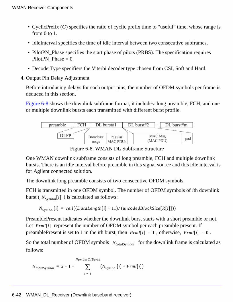
WMAN Receiver Components
• CyclicPrefix (G) specifies the ratio of cyclic prefix time to “useful” time, whose range is from 0 to 1.
• IdleInterval specifies the time of idle interval between two consecutive subframes.
• PilotPN_Phase specifies the start phase of pilots (PRBS). The specification requires PilotPN_Phase = 0.
• DecoderType specifiers the Viterbi decoder type chosen from CSI, Soft and Hard.
4. Output Pin Delay Adjustment
Before introducing delays for each output pins, the number of OFDM symbols per frame is deduced in this section.
Figure 6-8 shows the downlink subframe format, it includes: long preamble, FCH, and one or multiple downlink bursts each transmitted with different burst profile.
Figure 6-8. WMAN DL Subframe Structure
One WMAN downlink subframe consists of long preamble, FCH and multiple downlink bursts. There is an idle interval before preamble in this signal source and this idle interval is for Agilent connected solution.
The downlink long preamble consists of two consecutive OFDM symbols.
FCH is transmitted in one OFDM symbol. The number of OFDM symbols of ith downlink burst ( ) is calculated as follows:
PreamblePresent indicates whether the downlink burst starts with a short preamble or not. Let represent the number of OFDM symbol per each preamble present. If preamblePresent is set to 1 in the ith burst, then , otherwise, .
So the total number of OFDM symbols for the downlink frame is calculated as
follows:
NSymbol i[ ]
NSymbol i[ ] ceil DataLength i[ ] 11+( ) uncodedBlockSize R i[ ][ ]( )⁄( )=
Prml i[ ]Prml i[ ] 1= Prml i[ ] 0=
NtotalSymbol
NtotalSymbol 2 1 NSymbol i[ ] Prml i[ ]+( )i 1=
NumberOfBurst
∑+ +=
6-42 WMAN_DL_Receiver (Downlink baseband receiver)
The number of samples per one OFDM symbol ( ) is calculated as:
The samples of IdleInterval ( ) is calculated as:
So, the total samples of one downlink frame is
This model works on frame by fame. Each firing, tokens are consumed at
Pin FrameData.
For_EVM pin has one WMAN OFDM DL frame delay. This pin outputs all the number of OFDM symbols in one subframe except preambles. Each firing, pin For_EVM produces
tokens.
Moreover, the first
output signals at the For_EVM pin are zeros.
PSDUFCS has one frame delay. This pin outputs demodulated PSDU and FCS information bits after fully decoding (de-interleaving, Viterbi decoding and De-scrambling). So, the delay of PSDUFCS is . The first
bits at the PSDUFCS pin are zeros.
PSDU also has one frame delay. This pin outputs demodulated PSDU information bits after fully decoding (de-interleaving, Viterbi decoding and De-scrambling). So, the delay of PSDUFCS is . The first
bits at the PSDU pin ares zero.
CIR output pin also has one frame delay. Each firing, pin CIR produces
tokens. the first
SamplesOFDM
SamplesOFDM 2OversamplingOption
256× 1 G+( )×=
Nidle
Samplesidle IdleInterval 2OversamplingOption
Fs××=
SamplesFrame
SamplesFrame Samplesidle NtotalSymbol SamplesOFDM×+=
SamplesFrame
200 1 NSymbol i[ ]i 1=
NumberOfBurst
∑+
×
200 1 NSymbol i[ ]i 1=
NumberOfBurst
∑+
×
8 DataLength BurstWithFEC[ ]× 80+
8 DataLength BurstWithFEC[ ]× 80+
8 DataLength BurstWithFEC[ ]×8 DataLength× BurstWithFEC[ ]
200 1 prml i[ ]i 1=
NumberOfBurst
∑+
×
WMAN_DL_Receiver (Downlink baseband receiver) 6-43
WMAN Receiver Components
output signals at the CIR pin are zeros.
References
[1] IEEE Std 802.16-2004, “Part 16: Air Interface for Fixed Broadband Wireless Access Systems”, Section 8.3 WirelessMAN-OFDM PHY, October 1, 2004.
[2] IEEE P802.16-2004/Cor1/D3, “Corrigendum to IEEE Standard for Local and Metropolitan Area Networks - Part 16: Air Interface for Fixed Broadband Wireless Access Systems”, May 2005.
200 1 prml i[ ]i 1=
NumberOfBurst
∑+
×
6-44 WMAN_DL_Receiver (Downlink baseband receiver)
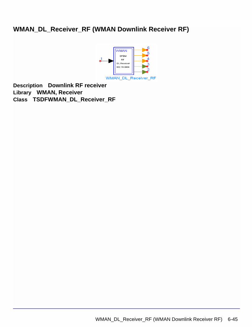
WMAN_DL_Receiver_RF (WMAN Downlink Receiver RF)
Description Downlink RF receiverLibrary WMAN, ReceiverClass TSDFWMAN_DL_Receiver_RF
WMAN_DL_Receiver_RF (WMAN Downlink Receiver RF) 6-45
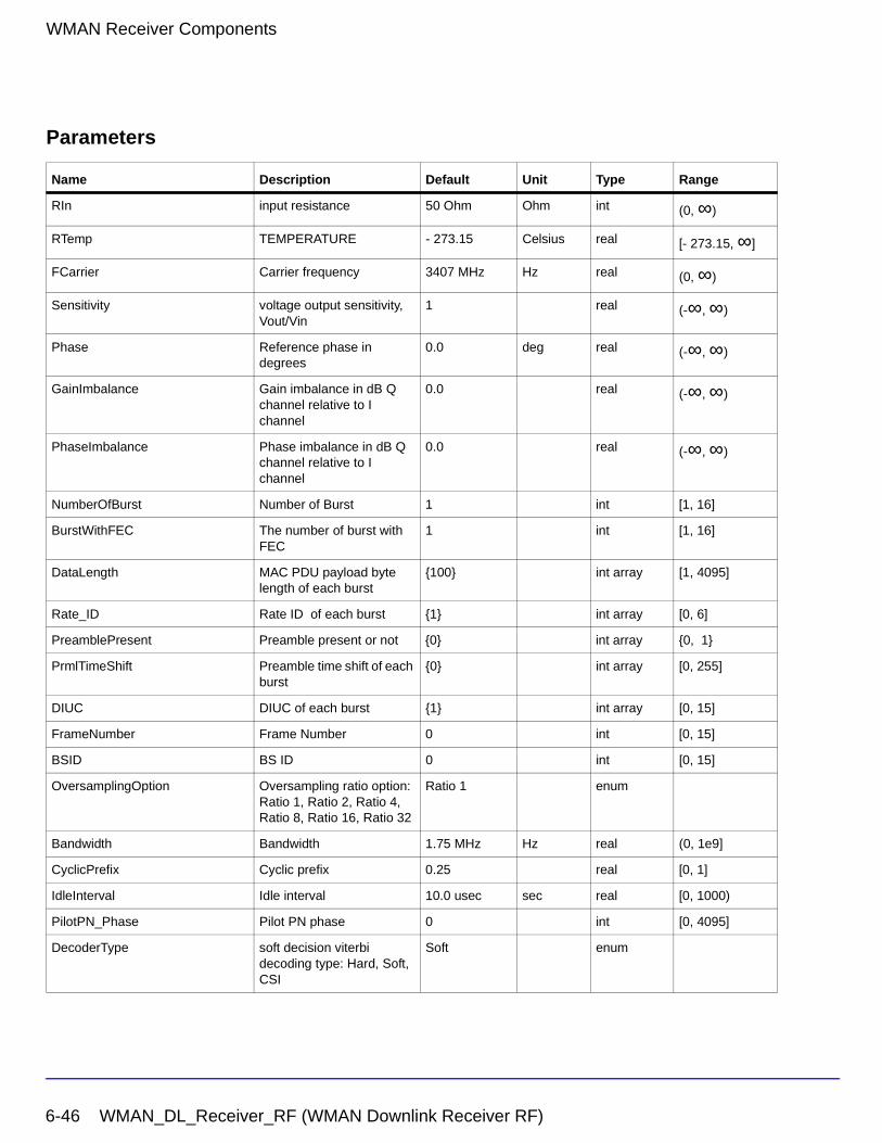
WMAN Receiver Components
Parameters
Name Description Default Unit Type Range
RIn input resistance 50 Ohm Ohm int (0, ∞)
RTemp TEMPERATURE - 273.15 Celsius real [- 273.15, ∞]
FCarrier Carrier frequency 3407 MHz Hz real (0, ∞)
Sensitivity voltage output sensitivity, Vout/Vin
1 real (-∞, ∞)
Phase Reference phase in degrees
0.0 deg real (-∞, ∞)
GainImbalance Gain imbalance in dB Q channel relative to I channel
0.0 real (-∞, ∞)
PhaseImbalance Phase imbalance in dB Q channel relative to I channel
0.0 real (-∞, ∞)
NumberOfBurst Number of Burst 1 int [1, 16]
BurstWithFEC The number of burst with FEC
1 int [1, 16]
DataLength MAC PDU payload byte length of each burst
{100} int array [1, 4095]
Rate_ID Rate ID of each burst {1} int array [0, 6]
PreamblePresent Preamble present or not {0} int array {0, 1}
PrmlTimeShift Preamble time shift of each burst
{0} int array [0, 255]
DIUC DIUC of each burst {1} int array [0, 15]
FrameNumber Frame Number 0 int [0, 15]
BSID BS ID 0 int [0, 15]
OversamplingOption Oversampling ratio option: Ratio 1, Ratio 2, Ratio 4, Ratio 8, Ratio 16, Ratio 32
Ratio 1 enum
Bandwidth Bandwidth 1.75 MHz Hz real (0, 1e9]
CyclicPrefix Cyclic prefix 0.25 real [0, 1]
IdleInterval Idle interval 10.0 usec sec real [0, 1000)
PilotPN_Phase Pilot PN phase 0 int [0, 4095]
DecoderType soft decision viterbi decoding type: Hard, Soft, CSI
Soft enum
6-46 WMAN_DL_Receiver_RF (WMAN Downlink Receiver RF)
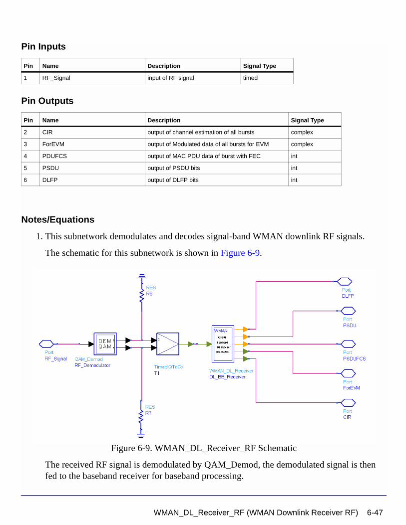
Pin Inputs
Pin Outputs
Notes/Equations
1. This subnetwork demodulates and decodes signal-band WMAN downlink RF signals.
The schematic for this subnetwork is shown in Figure 6-9.
Figure 6-9. WMAN_DL_Receiver_RF Schematic
The received RF signal is demodulated by QAM_Demod, the demodulated signal is then fed to the baseband receiver for baseband processing.
Pin Name Description Signal Type
1 RF_Signal input of RF signal timed
Pin Name Description Signal Type
2 CIR output of channel estimation of all bursts complex
3 ForEVM output of Modulated data of all bursts for EVM complex
4 PDUFCS output of MAC PDU data of burst with FEC int
5 PSDU output of PSDU bits int
6 DLFP output of DLFP bits int
WMAN_DL_Receiver_RF (WMAN Downlink Receiver RF) 6-47
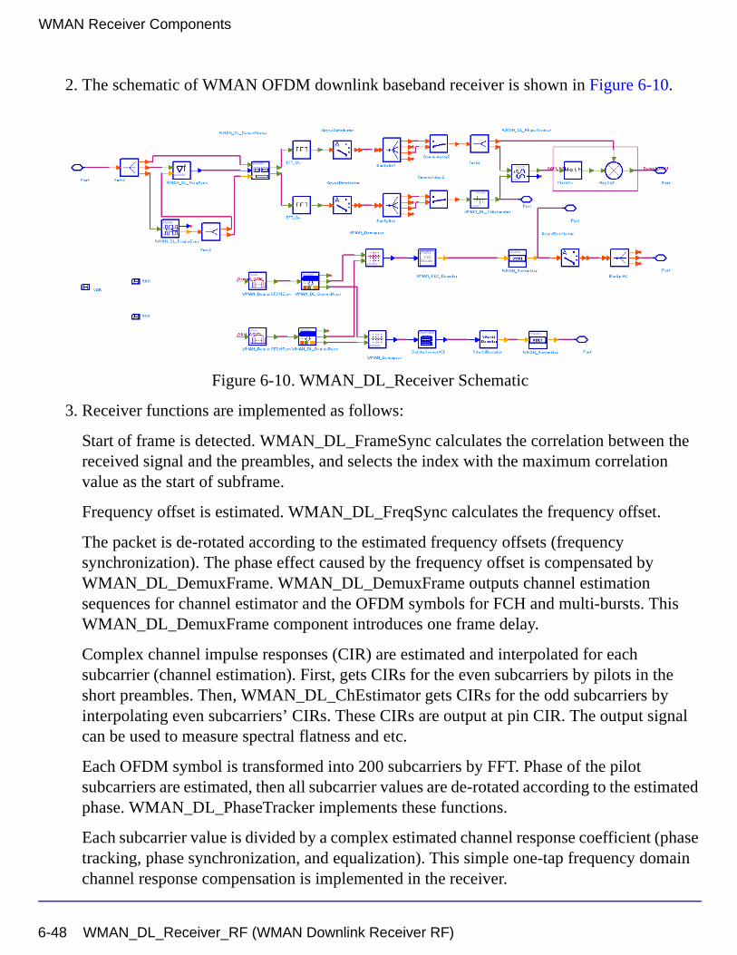
WMAN Receiver Components
2. The schematic of WMAN OFDM downlink baseband receiver is shown in Figure 6-10.
Figure 6-10. WMAN_DL_Receiver Schematic
3. Receiver functions are implemented as follows:
Start of frame is detected. WMAN_DL_FrameSync calculates the correlation between the received signal and the preambles, and selects the index with the maximum correlation value as the start of subframe.
Frequency offset is estimated. WMAN_DL_FreqSync calculates the frequency offset.
The packet is de-rotated according to the estimated frequency offsets (frequency synchronization). The phase effect caused by the frequency offset is compensated by WMAN_DL_DemuxFrame. WMAN_DL_DemuxFrame outputs channel estimation sequences for channel estimator and the OFDM symbols for FCH and multi-bursts. This WMAN_DL_DemuxFrame component introduces one frame delay.
Complex channel impulse responses (CIR) are estimated and interpolated for each subcarrier (channel estimation). First, gets CIRs for the even subcarriers by pilots in the short preambles. Then, WMAN_DL_ChEstimator gets CIRs for the odd subcarriers by interpolating even subcarriers’ CIRs. These CIRs are output at pin CIR. The output signal can be used to measure spectral flatness and etc.
Each OFDM symbol is transformed into 200 subcarriers by FFT. Phase of the pilot subcarriers are estimated, then all subcarrier values are de-rotated according to the estimated phase. WMAN_DL_PhaseTracker implements these functions.
Each subcarrier value is divided by a complex estimated channel response coefficient (phase tracking, phase synchronization, and equalization). This simple one-tap frequency domain channel response compensation is implemented in the receiver.
6-48 WMAN_DL_Receiver_RF (WMAN Downlink Receiver RF)
After equalization, the demodulated OFDM symbols for FCH and multi-bursts are output at pin For_EVM. The signal can be used to show the demodulated constellation and to calculate the RCE (relative constellation error) or EVM.
WMAN_DemuxOFDMSym de-multiplexes 200 subcarriers into 192 data subcarriers and 8 pilot subcarriers. WMAN_DemuxOFDMSym just outputs signal at 192 data subcarriers.
The burst with FEC-encoded is separated from the multi-bursts in WMAN_DL_DemuxBurst.
The demodulated OFDM symbols of burst with FEC are then de-mapped by WMAN_Demapper. Three demapper types (CSI, Soft and Hard) are supported in WMAN_Demapper.
After FEC decoding, de-interleaving, de-scrambling, the MAC PDU data are achieved, which are divided into MAC header, MAC PDU payloads and CRC. The MAC PDU and its payloads are output at pin PSDUFCS and PSDU respectively.
The demodulated FCH OFDM symbol is also de-mapped by WMAN_Demapper. After FEC decoding, de-interleaving, de-scrambling, the decoded DLFP is output at pin DLFP.
4. Parameter Details
• ROut is the RF output source resistance.
• RTemp is the RF output source resistance temperature in Celsius and sets the noise density in the RF output signal to (k(RTemp+273.15)) Watts/Hz, where k is Boltzmann's constant.
• FCarrier is the RF output signal frequency.
• Power is used to set the modulator output RF power. This is true for an ideal transmitted signal (no impairments added) or when small impairments are added. If large impairments are added to the signal (using GainImbalance, I_OriginOffset, and Q_OriginOffset parameters) the output RF power may be different from the value of the Power parameter.
• MirrorSpectrum is used to mirror the RF_out signal spectrum about the carrier. This is equivalent to conjugating the complex RF envelope voltage. Depending on the configuration and number of mixers in an RF transmitter, the RF output signal from hardware RF generators can be inverted. If such an RF signal is desired, set this parameter to YES.
• GainImbalance, PhaseImbalance, I_OriginOffset, Q_OriginOffset, and IQ_Rotation are used to add certain impairments to the ideal output RF signal. Impairments are added in the order described here.
WMAN_DL_Receiver_RF (WMAN Downlink Receiver RF) 6-49
WMAN Receiver Components
The unimpaired RF I and Q envelope voltages have gain and phase imbalance applied. The RF is given by:
where A is a scaling factor based on the Power and ROut parameters specified by the user, VI(t) is the in-phase RF envelope, VQ(t) is the quadrature phase RF envelope, g is
the gain imbalance
and, (in degrees) is the phase imbalance.
Next, the signal VRF(t) is rotated by IQ_Rotation degrees. The I_OriginOffset and
Q_OriginOffset are then applied to the rotated signal. Note that the amounts specified are percentages with respect to the output rms voltage. The output rms voltage is given by sqrt(2×ROut×Power)
• NumberOfBurst specifies the number of active downlink bursts.
• BurstWithFEC specifies the downlink burst with FEC.
• DataLength is the array of each DL burst's MAC PDU payload byte length. Rate_ID is the array of each DL burst's Rate ID, whose range is from 0 to 6. DataLength and Rate_ID (R) determine the number of data symbols per DL burst. Data-rate-dependent parameters (modulation, coding rate, coded bytes/uncoded bytes per OFDM symbol) are set according to Table 6-9, which is based on the specification.
Table 6-9. Mandatory Channel Coding per Modulation
Rate_ID(R) Modulation
Uncoded block size(bytes)
Coded block size(bytes)
Overall coding rate RS code CC code rate
0 BPSK 12 24 1/2 (12,12,0) 1/2
1 QPSK 24 48 1/2 (32,24,4) 2/3
2 QPSK 36 48 3/4 (40,36,2) 5/6
3 16-QAM 48 96 1/2 (64,48,8) 2/3
4 16-QAM 72 96 3/4 (80,72,4) 5/6
5 64-QAM 96 144 2/3 (108,96,6) 3/4
6 64-QAM 108 144 3/4 (120,108,6) 5/6
VRF t( ) A VI t( ) ωct( )cos gVQ t( ) ωctΦπ180---------+
sin– =
g 10
GainImbalance20
-----------------------------------------
=
φ
6-50 WMAN_DL_Receiver_RF (WMAN Downlink Receiver RF)
• PreamblePresent is the array of each DL burst’s preamble present. It determines whether preamble is placed before the burst or not. If “1,” preamble is placed before the burst, otherwise preamble is not placed before the burst.
• PrmlTimeShift is an array parameter. Its size should be same as NumberOfBurst and it determines the number of samples of cyclic shift delay in time for the preamble symbols
• DIUC, FrameNumber, BSID are used to generate the scrambler DL initialization vector.
• OversamplingOption indicates the oversampling ratio of transmission signal. There are six oversampling ratios (1, 2, 4, 8, 16, 32) to support in this receiver. For example, if OversamplingOption = Ratio 2, it means the IFFT size is 512.
• Bandwidth determines the nominal channel bandwidth. The sampling frequency (Fs) implemented in the design is decided by Bandwidth, OversamplingOption and related sampling factor as follows,
The sampling factors are listed in Table 6-10.
Fs floor Nfactor Bandwidth×( ) 8000⁄( ) 8000×( ) 2OversamplingOption×=
WMAN_DL_Receiver_RF (WMAN Downlink Receiver RF) 6-51
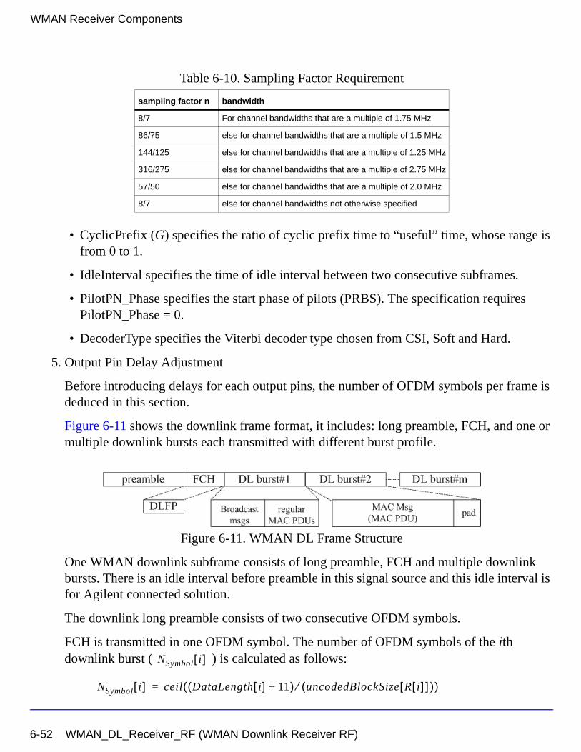
WMAN Receiver Components
• CyclicPrefix (G) specifies the ratio of cyclic prefix time to “useful” time, whose range is from 0 to 1.
• IdleInterval specifies the time of idle interval between two consecutive subframes.
• PilotPN_Phase specifies the start phase of pilots (PRBS). The specification requires PilotPN_Phase = 0.
• DecoderType specifies the Viterbi decoder type chosen from CSI, Soft and Hard.
5. Output Pin Delay Adjustment
Before introducing delays for each output pins, the number of OFDM symbols per frame is deduced in this section.
Figure 6-11 shows the downlink frame format, it includes: long preamble, FCH, and one or multiple downlink bursts each transmitted with different burst profile.
Figure 6-11. WMAN DL Frame Structure
One WMAN downlink subframe consists of long preamble, FCH and multiple downlink bursts. There is an idle interval before preamble in this signal source and this idle interval is for Agilent connected solution.
The downlink long preamble consists of two consecutive OFDM symbols.
FCH is transmitted in one OFDM symbol. The number of OFDM symbols of the ith downlink burst ( ) is calculated as follows:
Table 6-10. Sampling Factor Requirement
sampling factor n bandwidth
8/7 For channel bandwidths that are a multiple of 1.75 MHz
86/75 else for channel bandwidths that are a multiple of 1.5 MHz
144/125 else for channel bandwidths that are a multiple of 1.25 MHz
316/275 else for channel bandwidths that are a multiple of 2.75 MHz
57/50 else for channel bandwidths that are a multiple of 2.0 MHz
8/7 else for channel bandwidths not otherwise specified
NSymbol i[ ]
NSymbol i[ ] ceil DataLength i[ ] 11+( ) uncodedBlockSize R i[ ][ ]( )⁄( )=
6-52 WMAN_DL_Receiver_RF (WMAN Downlink Receiver RF)
PreamblePresent indicates whether the downlink burst starts with a short preamble or not. Let represent the number of OFDM symbol per each preamble present. If PreamblePresent is set to 1 in the ith burst, then , otherwise, .
So the total number of OFDM symbols for the downlink frame is calculated as
follows:
The number of samples per one OFDM symbol ( ) is calculated as:
The samples of IdleInterval ( ) is calculated as follows:
So, the total samples of one downlink frame is
This model work on frame by fame. Each firing, tokens are consumed at Pin
FrameData.
For_EVM pin has one WMAN OFDM DL frame delay. This pin outputs all the number OFDM symbols except preambles. Each firing, pin For_EVM produces
tokens. Moreover, the first
output signals at the For_EVM pin are zeros.
PSDUFCS has one frame delay. This pin outputs demodulated PSDU and FCS information bits after fully decoding (de-interleaving, Viterbi decoding and De-scrambling). So, the delay of PSDUFCS is
.
Prml i[ ]Prml i[ ] 1= Prml i[ ] 0=
NtotalSymbol
NtotalSymbol 2 1 NSymbol i[ ] Prml i[ ]+( )i 1=
NumberOfBurst
∑+ +=
SamplesOFDM
SamplesOFDM 2OversamplingOption
256× 1 G+( )×=
Nidle
Samplesidle IdleInterval 2OversamplingOption
Fs××=
SamplesFrame
SamplesFrame Samplesidle NtotalSymbol SamplesOFDM×+=
SamplesFrame
200 1 NSymbol i[ ]i 1=
NumberOfBurst
∑+
×
200 1 NSymbol i[ ]i 1=
NumberOfBurst
∑+
×
8 DataLength BurstWithFEC[ ]× 80+
WMAN_DL_Receiver_RF (WMAN Downlink Receiver RF) 6-53
WMAN Receiver Components
The first
bits at the PSDUFCS pin are zeros.
PSDU also has one frame delay. This pin outputs demodulated PSDU information bits after fully decoding (de-interleaving, Viterbi decoding and De-scrambling). So, the delay of PSDUFCS is . The first
bits at the PSDU pin ares zero.
CIR output pin also has one frame delay. Each firing, pin CIR produces
tokens. The first
output signals at the CIR pin are zeros.
References
[1] IEEE Std 802.16-2004, Part 16: Air Interface for Fixed Broadband Wireless Access Systems, Section 8.3 WirelessMAN-OFDM PHY, October 1, 2004.
[2] IEEE P802.16-2004/Cor1/D3, Corrigendum to IEEE Standard for Local and Metropolitan Area Networks - Part 16: Air Interface for Fixed Broadband Wireless Access Systems, May 2005.
8 DataLength BurstWithFEC[ ]× 80+
8 DataLength BurstWithFEC[ ]×8 DataLength× BurstWithFEC[ ]
200 1 prml i[ ]i 1=
NumberOfBurst
∑+
×
200 1 prml i[ ]i 1=
NumberOfBurst
∑+
×
6-54 WMAN_DL_Receiver_RF (WMAN Downlink Receiver RF)
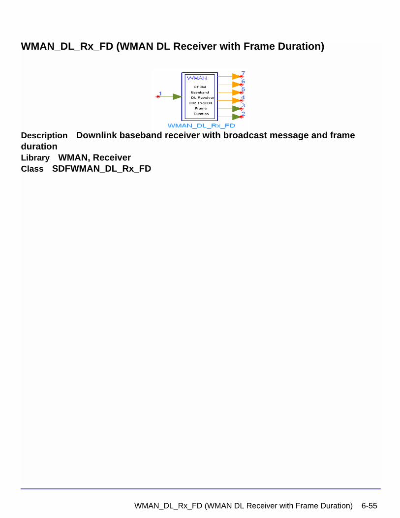
WMAN_DL_Rx_FD (WMAN DL Receiver with Frame Duration)
Description Downlink baseband receiver with broadcast message and frame durationLibrary WMAN, ReceiverClass SDFWMAN_DL_Rx_FD
WMAN_DL_Rx_FD (WMAN DL Receiver with Frame Duration) 6-55
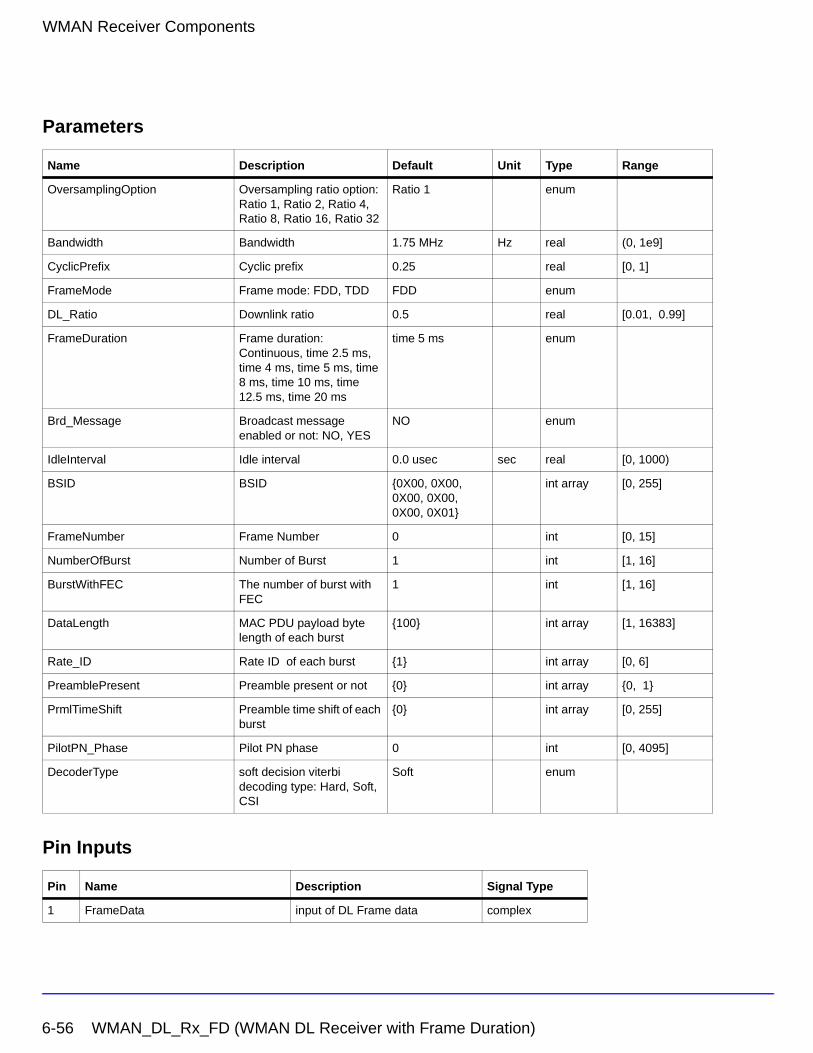
WMAN Receiver Components
Parameters
Pin Inputs
Name Description Default Unit Type Range
OversamplingOption Oversampling ratio option: Ratio 1, Ratio 2, Ratio 4, Ratio 8, Ratio 16, Ratio 32
Ratio 1 enum
Bandwidth Bandwidth 1.75 MHz Hz real (0, 1e9]
CyclicPrefix Cyclic prefix 0.25 real [0, 1]
FrameMode Frame mode: FDD, TDD FDD enum
DL_Ratio Downlink ratio 0.5 real [0.01, 0.99]
FrameDuration Frame duration: Continuous, time 2.5 ms, time 4 ms, time 5 ms, time 8 ms, time 10 ms, time 12.5 ms, time 20 ms
time 5 ms enum
Brd_Message Broadcast message enabled or not: NO, YES
NO enum
IdleInterval Idle interval 0.0 usec sec real [0, 1000)
BSID BSID {0X00, 0X00, 0X00, 0X00, 0X00, 0X01}
int array [0, 255]
FrameNumber Frame Number 0 int [0, 15]
NumberOfBurst Number of Burst 1 int [1, 16]
BurstWithFEC The number of burst with FEC
1 int [1, 16]
DataLength MAC PDU payload byte length of each burst
{100} int array [1, 16383]
Rate_ID Rate ID of each burst {1} int array [0, 6]
PreamblePresent Preamble present or not {0} int array {0, 1}
PrmlTimeShift Preamble time shift of each burst
{0} int array [0, 255]
PilotPN_Phase Pilot PN phase 0 int [0, 4095]
DecoderType soft decision viterbi decoding type: Hard, Soft, CSI
Soft enum
Pin Name Description Signal Type
1 FrameData input of DL Frame data complex
6-56 WMAN_DL_Rx_FD (WMAN DL Receiver with Frame Duration)
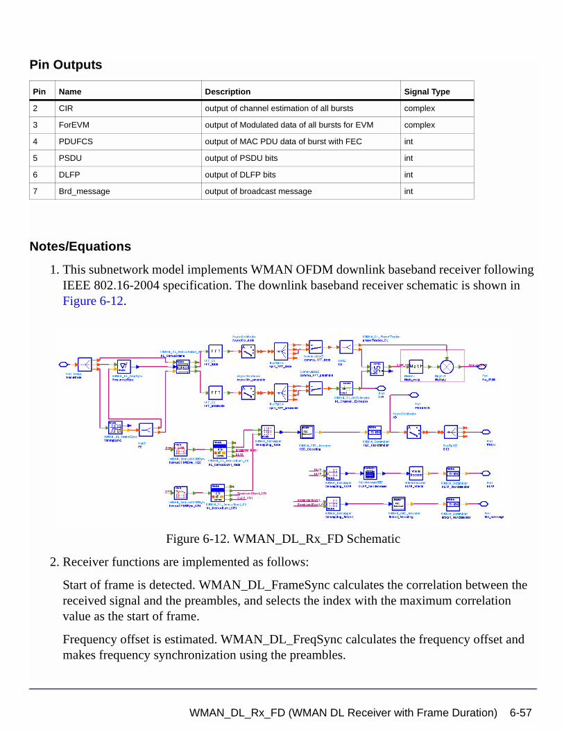
Pin Outputs
Notes/Equations
1. This subnetwork model implements WMAN OFDM downlink baseband receiver following IEEE 802.16-2004 specification. The downlink baseband receiver schematic is shown in Figure 6-12.
Figure 6-12. WMAN_DL_Rx_FD Schematic
2. Receiver functions are implemented as follows:
Start of frame is detected. WMAN_DL_FrameSync calculates the correlation between the received signal and the preambles, and selects the index with the maximum correlation value as the start of frame.
Frequency offset is estimated. WMAN_DL_FreqSync calculates the frequency offset and makes frequency synchronization using the preambles.
Pin Name Description Signal Type
2 CIR output of channel estimation of all bursts complex
3 ForEVM output of Modulated data of all bursts for EVM complex
4 PDUFCS output of MAC PDU data of burst with FEC int
5 PSDU output of PSDU bits int
6 DLFP output of DLFP bits int
7 Brd_message output of broadcast message int
WMAN_DL_Rx_FD (WMAN DL Receiver with Frame Duration) 6-57
WMAN Receiver Components
The packet is de-rotated according to the estimated frequency offsets (frequency synchronization). The phase effect caused by the frequency offset is compensated by WMAN_DL_DemuxFrame_FD. WMAN_DL_DemuxFrame_FD outputs channel estimation sequences and the OFDM symbols for FCH, broadcast burst and multi-bursts. This WMAN_DL_DemuxFrame_FD component introduces one frame delay.
Complex channel impulse responses (CIR) are estimated and interpolated for each subcarrier (channel estimation). First, WMAN_DL_ChEstimator gets CIRs for the even subcarriers by pilots in the short preambles or midambles. Then, WMAN_DL_ChEstimator gets CIRs for the odd subcarriers by interpolating even subcarriers’ CIRs. These CIRs are output at pin CIR. The output signal can be used to measure spectral flatness and etc.
Each OFDM symbol is transformed into 200 subcarriers by FFT. Phase of the pilot subcarriers are estimated, then all subcarrier values are de-rotated according to the estimated phase. WMAN_DL_PhaseTracker implements these functions.
Each subcarrier value is divided by a complex estimated channel response coefficient (phase tracking, phase synchronization, and equalization). This simple one-tap frequency domain channel response compensation is implemented in the receiver.
After equalization, the demodulated OFDM symbols for FCH and multi-bursts are output at pin For_EVM. The signal can be used to show the demodulated constellation and to calculate the RCE (relative constellation error) or EVM.
WMAN_DemuxOFDMSym de-multiplexes 200 subcarriers into 192 data subcarriers and 8 pilot subcarriers. WMAN_DemuxOFDMSym just outputs signal at 192 data subcarriers.
The burst with FEC-encoded is separated from the multi-bursts in WMAN_DL_DemuxBurst_FD.
The demodulated OFDM symbols of burst with FEC are then de-mapped by WMAN_Demapper. Three demapper types (CSI, Soft and Hard) are supported in WMAN_Demaper.
After FEC decoding, de-interleaving, de-scrambling, the MAC PDU data are achieved, which are divided into MAC header, MAC PDU payloads and CRC. The MAC PDU and its payloads are output at pin PDUFCS and PSDU respectively.
The demodulated FCH OFDM symbol is also de-mapped by WMAN_Demapper. After FEC decoding, de-interleaving, de-scrambling, the decoded DLFP is output at pin DLFP.
The decoded broadcast messages are output at pin Brd_message.
3. Parameter Details
• NumberOfBurst specifies the number of active downlink bursts.
6-58 WMAN_DL_Rx_FD (WMAN DL Receiver with Frame Duration)
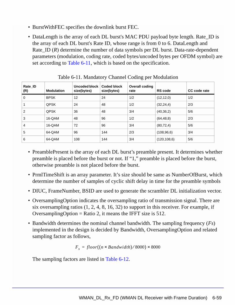
• BurstWithFEC specifies the downlink burst FEC.
• DataLength is the array of each DL burst's MAC PDU payload byte length. Rate_ID is the array of each DL burst's Rate ID, whose range is from 0 to 6. DataLength and Rate_ID (R) determine the number of data symbols per DL burst. Data-rate-dependent parameters (modulation, coding rate, coded bytes/uncoded bytes per OFDM symbol) are set according to Table 6-11, which is based on the specification.
• PreamblePresent is the array of each DL burst’s preamble present. It determines whether preamble is placed before the burst or not. If “1,” preamble is placed before the burst, otherwise preamble is not placed before the burst.
• PrmlTimeShift is an array parameter. It’s size should be same as NumberOfBurst, which determine the number of samples of cyclic shift delay in time for the preamble symbols
• DIUC, FrameNumber, BSID are used to generate the scrambler DL initialization vector.
• OversamplingOption indicates the oversampling ratio of transmission signal. There are six oversampling ratios (1, 2, 4, 8, 16, 32) to support in this receiver. For example, if OversamplingOption = Ratio 2, it means the IFFT size is 512.
• Bandwidth determines the nominal channel bandwidth. The sampling frequency (Fs) implemented in the design is decided by Bandwidth, OversamplingOption and related sampling factor as follows,
The sampling factors are listed in Table 6-12.
Table 6-11. Mandatory Channel Coding per Modulation
Rate_ID(R) Modulation
Uncoded block size(bytes)
Coded block size(bytes)
Overall coding rate RS code CC code rate
0 BPSK 12 24 1/2 (12,12,0) 1/2
1 QPSK 24 48 1/2 (32,24,4) 2/3
2 QPSK 36 48 3/4 (40,36,2) 5/6
3 16-QAM 48 96 1/2 (64,48,8) 2/3
4 16-QAM 72 96 3/4 (80,72,4) 5/6
5 64-QAM 96 144 2/3 (108,96,6) 3/4
6 64-QAM 108 144 3/4 (120,108,6) 5/6
Fs floor n Bandwidth×( ) 8000⁄( ) 8000×=
WMAN_DL_Rx_FD (WMAN DL Receiver with Frame Duration) 6-59
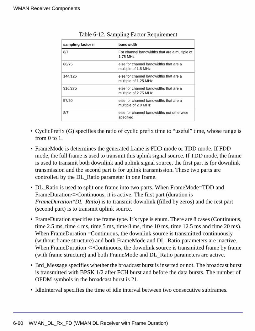
WMAN Receiver Components
• CyclicPrefix (G) specifies the ratio of cyclic prefix time to “useful” time, whose range is from 0 to 1.
• FrameMode is determines the generated frame is FDD mode or TDD mode. If FDD mode, the full frame is used to transmit this uplink signal source. If TDD mode, the frame is used to transmit both downlink and uplink signal source, the first part is for downlink transmission and the second part is for uplink transmission. These two parts are controlled by the DL_Ratio parameter in one frame.
• DL_Ratio is used to split one frame into two parts. When FrameMode=TDD and FrameDuration<>Continuous, it is active. The first part (duration is FrameDuration*DL_Ratio) is to transmit downlink (filled by zeros) and the rest part (second part) is to transmit uplink source.
• FrameDuration specifies the frame type. It’s type is enum. There are 8 cases (Continuous, time 2.5 ms, time 4 ms, time 5 ms, time 8 ms, time 10 ms, time 12.5 ms and time 20 ms). When FrameDuration =Continuous, the downlink source is transmitted continuously (without frame structure) and both FrameMode and DL_Ratio parameters are inactive. When FrameDuration <>Continuous, the downlink source is transmitted frame by frame (with frame structure) and both FrameMode and DL_Ratio parameters are active.
• Brd_Message specifies whether the broadcast burst is inserted or not. The broadcast burst is transmitted with BPSK 1/2 after FCH burst and before the data bursts. The number of OFDM symbols in the broadcast burst is 21.
• IdleInterval specifies the time of idle interval between two consecutive subframes.
Table 6-12. Sampling Factor Requirement
sampling factor n bandwidth
8/7 For channel bandwidths that are a multiple of 1.75 MHz
86/75 else for channel bandwidths that are a multiple of 1.5 MHz
144/125 else for channel bandwidths that are a multiple of 1.25 MHz
316/275 else for channel bandwidths that are a multiple of 2.75 MHz
57/50 else for channel bandwidths that are a multiple of 2.0 MHz
8/7 else for channel bandwidths not otherwise specified
6-60 WMAN_DL_Rx_FD (WMAN DL Receiver with Frame Duration)
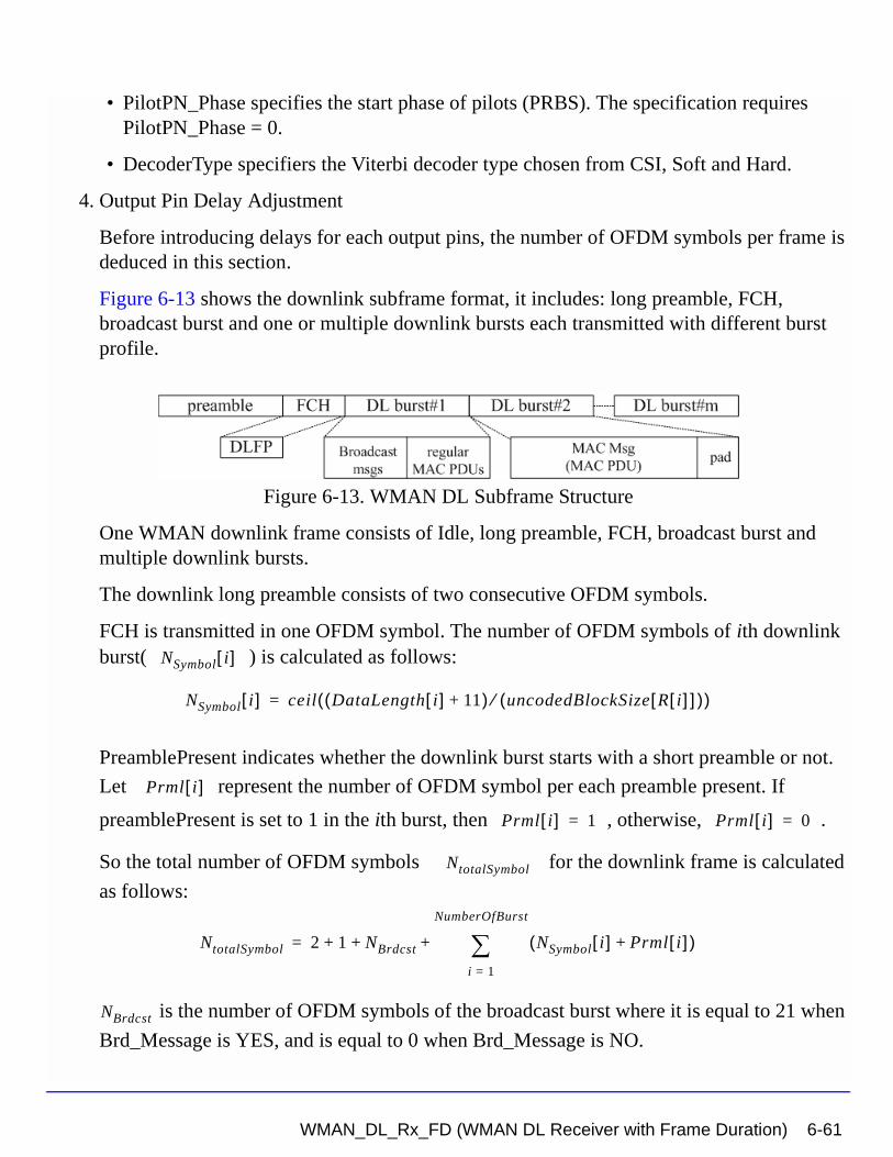
• PilotPN_Phase specifies the start phase of pilots (PRBS). The specification requires PilotPN_Phase = 0.
• DecoderType specifiers the Viterbi decoder type chosen from CSI, Soft and Hard.
4. Output Pin Delay Adjustment
Before introducing delays for each output pins, the number of OFDM symbols per frame is deduced in this section.
Figure 6-13 shows the downlink subframe format, it includes: long preamble, FCH, broadcast burst and one or multiple downlink bursts each transmitted with different burst profile.
Figure 6-13. WMAN DL Subframe Structure
One WMAN downlink frame consists of Idle, long preamble, FCH, broadcast burst and multiple downlink bursts.
The downlink long preamble consists of two consecutive OFDM symbols.
FCH is transmitted in one OFDM symbol. The number of OFDM symbols of ith downlink burst( ) is calculated as follows:
PreamblePresent indicates whether the downlink burst starts with a short preamble or not.
Let represent the number of OFDM symbol per each preamble present. If
preamblePresent is set to 1 in the ith burst, then , otherwise, .
So the total number of OFDM symbols for the downlink frame is calculated
as follows:
is the number of OFDM symbols of the broadcast burst where it is equal to 21 when
Brd_Message is YES, and is equal to 0 when Brd_Message is NO.
NSymbol i[ ]
NSymbol i[ ] ceil DataLength i[ ] 11+( ) uncodedBlockSize R i[ ][ ]( )⁄( )=
Prml i[ ]
Prml i[ ] 1= Prml i[ ] 0=
NtotalSymbol
NtotalSymbol 2 1 NBrdcst NSymbol i[ ] Prml i[ ]+( )i 1=
NumberOfBurst
∑+ + +=
NBrdcst
WMAN_DL_Rx_FD (WMAN DL Receiver with Frame Duration) 6-61
WMAN Receiver Components
The number of samples per one OFDM symbol ( ) is calculated as:
The samples of IdleInterval( ) is calculated as follows:
If FrameDuration is Continuous, the total samples of one downlink frame
is
Otherwise, if FrameDuration is set to other values (2.5 ms, 4 ms, 5 ms, 8 ms, 10 ms, 12.5 ms
or 20 ms), the total samples of one downlink frame is
This model work on frame by fame. Each firing, tokens are consumed at Pin
FrameData.
For_EVM pin has one WMAN OFDM DL frame delay. This pin outputs all the number OFDM symbols except preambles. Each firing, pin For_EVM produces
tokens. Moreover, the first
output signals at the For_EVM pin are zeros.
PSDUFCS has one frame delay. This pin outputs demodulated PSDU and FCS information bits after fully decoding (de-interleaving, Viterbi decoding and De-scrambling). So, the
delay of PSDUFCS is . The first
bits at the PSDUFCS pin ares zero.
PSDU also has one frame delay. This pin outputs demodulated PSDU information bits after fully decoding (de-interleaving, Viterbi decoding and De-scrambling). So, the delay of
SamplesOFDM
SamplesOFDM 2OversamplingOption
256× 1 G+( )×=
Nidle
Samplesidle IdleInterval 2OversamplingOption
Fs××=
SamplesFrame
SamplesFrame Samplesidle NtotalSymbol SamplesOFDM×+=
SamplesFrame
SamplesFrame Samplesidle FrameDuration Fs 2× OversamplingOption×+=
SamplesFrame
200 1 NBrdcst NSymbol i[ ]i 1=
NumberOfBurst
∑+ +
×
200 1 NBrdcst NSymbol i[ ]i 1=
NumberOfBurst
∑+ +
×
8 DataLength BurstWithFEC[ ]× 80+
8 DataLength BurstWithFEC[ ]× 80+
6-62 WMAN_DL_Rx_FD (WMAN DL Receiver with Frame Duration)
PSDUFCS is . The first
bits at the PSDU pin ares zero.
CIR output pin also has one frame delay. Each firing, pin CIR produces
tokens. the first output
signals at the CIR pin are zeros.
References
[1] IEEE Std 802.16-2004, “Part 16: Air Interface for Fixed Broadband Wireless Access Systems”, Section 8.3 WirelessMAN-OFDM PHY, October 1, 2004.
[2] IEEE P802.16-2004/Cor1/D5, Corrigendum to IEEE Standard for Local and Metropolitan Area Networks - Part 16: Air Interface for Fixed Broadband Wireless Access Systems, Sept. 2005.
8 DataLength BurstWithFEC[ ]×
8 DataLength× BurstWithFEC[ ]
200 1 prml i[ ]i 1=
NumberOfBurst
∑+
× 200 1 prml i[ ]i 1=
NumberOfBurst
∑+
×
WMAN_DL_Rx_FD (WMAN DL Receiver with Frame Duration) 6-63
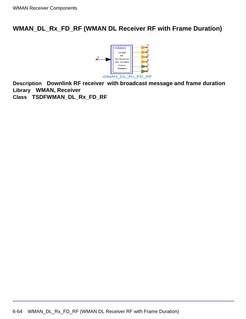
WMAN Receiver Components
WMAN_DL_Rx_FD_RF (WMAN DL Receiver RF with Frame Duration)
Description Downlink RF receiver with broadcast message and frame durationLibrary WMAN, ReceiverClass TSDFWMAN_DL_Rx_FD_RF
6-64 WMAN_DL_Rx_FD_RF (WMAN DL Receiver RF with Frame Duration)
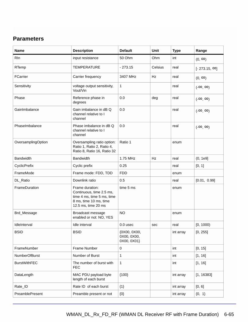
Parameters
Name Description Default Unit Type Range
RIn input resistance 50 Ohm Ohm int (0, ∞)
RTemp TEMPERATURE - 273.15 Celsius real [- 273.15, ∞]
FCarrier Carrier frequency 3407 MHz Hz real (0, ∞)
Sensitivity voltage output sensitivity, Vout/Vin
1 real (-∞, ∞)
Phase Reference phase in degrees
0.0 deg real (-∞, ∞)
GainImbalance Gain imbalance in dB Q channel relative to I channel
0.0 real (-∞, ∞)
PhaseImbalance Phase imbalance in dB Q channel relative to I channel
0.0 real (-∞, ∞)
OversamplingOption Oversampling ratio option: Ratio 1, Ratio 2, Ratio 4, Ratio 8, Ratio 16, Ratio 32
Ratio 1 enum
Bandwidth Bandwidth 1.75 MHz Hz real (0, 1e9]
CyclicPrefix Cyclic prefix 0.25 real [0, 1]
FrameMode Frame mode: FDD, TDD FDD enum
DL_Ratio Downlink ratio 0.5 real [0.01, 0.99]
FrameDuration Frame duration: Continuous, time 2.5 ms, time 4 ms, time 5 ms, time 8 ms, time 10 ms, time 12.5 ms, time 20 ms
time 5 ms enum
Brd_Message Broadcast message enabled or not: NO, YES
NO enum
IdleInterval Idle interval 0.0 usec sec real [0, 1000)
BSID BSID {0X00, 0X00, 0X00, 0X00, 0X00, 0X01}
int array [0, 255]
FrameNumber Frame Number 0 int [0, 15]
NumberOfBurst Number of Burst 1 int [1, 16]
BurstWithFEC The number of burst with FEC
1 int [1, 16]
DataLength MAC PDU payload byte length of each burst
{100} int array [1, 16383]
Rate_ID Rate ID of each burst {1} int array [0, 6]
PreamblePresent Preamble present or not {0} int array {0, 1}
WMAN_DL_Rx_FD_RF (WMAN DL Receiver RF with Frame Duration) 6-65
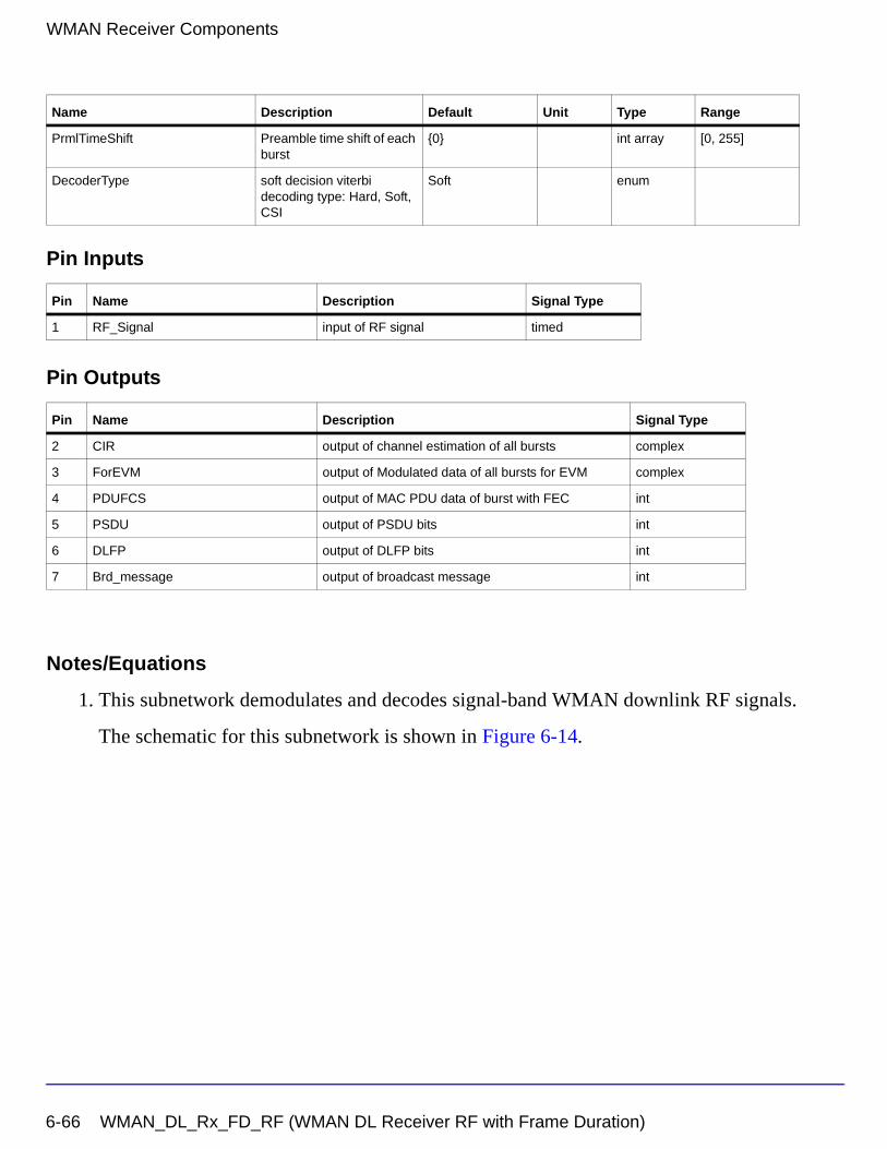
WMAN Receiver Components
Pin Inputs
Pin Outputs
Notes/Equations
1. This subnetwork demodulates and decodes signal-band WMAN downlink RF signals.
The schematic for this subnetwork is shown in Figure 6-14.
PrmlTimeShift Preamble time shift of each burst
{0} int array [0, 255]
DecoderType soft decision viterbi decoding type: Hard, Soft, CSI
Soft enum
Pin Name Description Signal Type
1 RF_Signal input of RF signal timed
Pin Name Description Signal Type
2 CIR output of channel estimation of all bursts complex
3 ForEVM output of Modulated data of all bursts for EVM complex
4 PDUFCS output of MAC PDU data of burst with FEC int
5 PSDU output of PSDU bits int
6 DLFP output of DLFP bits int
7 Brd_message output of broadcast message int
Name Description Default Unit Type Range
6-66 WMAN_DL_Rx_FD_RF (WMAN DL Receiver RF with Frame Duration)
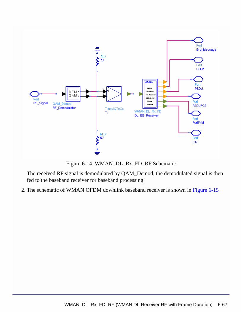
Figure 6-14. WMAN_DL_Rx_FD_RF Schematic
The received RF signal is demodulated by QAM_Demod, the demodulated signal is then fed to the baseband receiver for baseband processing.
2. The schematic of WMAN OFDM downlink baseband receiver is shown in Figure 6-15
WMAN_DL_Rx_FD_RF (WMAN DL Receiver RF with Frame Duration) 6-67
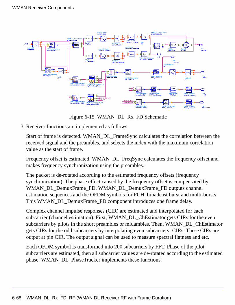
WMAN Receiver Components
Figure 6-15. WMAN_DL_Rx_FD Schematic
3. Receiver functions are implemented as follows:
Start of frame is detected. WMAN_DL_FrameSync calculates the correlation between the received signal and the preambles, and selects the index with the maximum correlation value as the start of frame.
Frequency offset is estimated. WMAN_DL_FreqSync calculates the frequency offset and makes frequency synchronization using the preambles.
The packet is de-rotated according to the estimated frequency offsets (frequency synchronization). The phase effect caused by the frequency offset is compensated by WMAN_DL_DemuxFrame_FD. WMAN_DL_DemuxFrame_FD outputs channel estimation sequences and the OFDM symbols for FCH, broadcast burst and multi-bursts. This WMAN_DL_DemuxFrame_FD component introduces one frame delay.
Complex channel impulse responses (CIR) are estimated and interpolated for each subcarrier (channel estimation). First, WMAN_DL_ChEstimator gets CIRs for the even subcarriers by pilots in the short preambles or midambles. Then, WMAN_DL_ChEstimator gets CIRs for the odd subcarriers by interpolating even subcarriers’ CIRs. These CIRs are output at pin CIR. The output signal can be used to measure spectral flatness and etc.
Each OFDM symbol is transformed into 200 subcarriers by FFT. Phase of the pilot subcarriers are estimated, then all subcarrier values are de-rotated according to the estimated phase. WMAN_DL_PhaseTracker implements these functions.
6-68 WMAN_DL_Rx_FD_RF (WMAN DL Receiver RF with Frame Duration)
Each subcarrier value is divided by a complex estimated channel response coefficient (phase tracking, phase synchronization, and equalization). This simple one-tap frequency domain channel response compensation is implemented in the receiver.
After equalization, the demodulated OFDM symbols for FCH and multi-bursts are output at pin For_EVM. The signal can be used to show the demodulated constellation and to calculate the RCE (relative constellation error) or EVM.
WMAN_DemuxOFDMSym de-multiplexes 200 subcarriers into 192 data subcarriers and 8 pilot subcarriers. WMAN_DemuxOFDMSym just outputs signal at 192 data subcarriers.
The burst with FEC-encoded is separated from the multi-bursts in WMAN_DL_DemuxBurst_FD.
The demodulated OFDM symbols of burst with FEC are then de-mapped by WMAN_Demapper. Three demapper types (CSI, Soft and Hard) are supported in WMAN_Demaper.
After FEC decoding, de-interleaving, de-scrambling, the MAC PDU data are achieved, which are divided into MAC header, MAC PDU payloads and CRC. The MAC PDU and its payloads are output at pin PDUFCS and PSDU respectively.
The demodulated FCH OFDM symbol is also de-mapped by WMAN_Demapper. After FEC decoding, de-interleaving, de-scrambling, the decoded DLFP is output at pin DLFP.
The decoded broadcast messages are output at pin Brd_message.
4. Parameter Details
• ROut is the RF output source resistance.
• RTemp is the RF output source resistance temperature in Celsius and sets the noise density in the RF output signal to (k(RTemp+273.15)) Watts/Hz, where k is Boltzmann's constant.
• FCarrier is the RF output signal frequency.
• Power is used to set the modulator output RF power. This is true for an ideal transmitted signal (no impairments added) or when small impairments are added. If large impairments are added to the signal (using GainImbalance, I_OriginOffset, and Q_OriginOffset parameters) the output RF power may be different from the value of the Power parameter.
• MirrorSpectrum is used to mirror the RF_out signal spectrum about the carrier. This is equivalent to conjugating the complex RF envelope voltage. Depending on the configuration and number of mixers in an RF transmitter, the RF output signal from
WMAN_DL_Rx_FD_RF (WMAN DL Receiver RF with Frame Duration) 6-69
WMAN Receiver Components
hardware RF generators can be inverted. If such an RF signal is desired, set this parameter to YES.
• GainImbalance, PhaseImbalance, I_OriginOffset, Q_OriginOffset, and IQ_Rotation are used to add certain impairments to the ideal output RF signal. Impairments are added in the order described here.
The unimpaired RF I and Q envelope voltages have gain and phase imbalance applied. The RF is given by:
where A is a scaling factor based on the Power and ROut parameters specified by the user, VI(t) is the in-phase RF envelope, VQ(t) is the quadrature phase RF envelope, g is
the gain imbalance
and, (in degrees) is the phase imbalance.
Next, the signal VRF(t) is rotated by IQ_Rotation degrees. The I_OriginOffset and
Q_OriginOffset are then applied to the rotated signal. Note that the amounts specified are percentages with respect to the output rms voltage. The output rms voltage is given by sqrt(2×ROut×Power)
• NumberOfBurst specifies the number of active downlink bursts.
• BurstWithFEC specifies the downlink burst FEC.
• DataLength is the array of each DL burst's MAC PDU payload byte length. Rate_ID is the array of each DL burst's Rate ID, whose range is from 0 to 6. DataLength and Rate_ID (R) determine the number of data symbols per DL burst. Data-rate-dependent parameters (modulation, coding rate, coded bytes/uncoded bytes per OFDM symbol) are set according to Table 6-13, which is based on the specification.
Table 6-13. Mandatory Channel Coding per Modulation
Rate_ID(R) Modulation
Uncoded block size(bytes)
Coded block size(bytes)
Overall coding rate RS code CC code rate
0 BPSK 12 24 1/2 (12,12,0) 1/2
1 QPSK 24 48 1/2 (32,24,4) 2/3
2 QPSK 36 48 3/4 (40,36,2) 5/6
3 16-QAM 48 96 1/2 (64,48,8) 2/3
VRF t( ) A VI t( ) ωct( )cos gVQ t( ) ωctΦπ180---------+
sin– =
g 10
GainImbalance20
-----------------------------------------
=
φ
6-70 WMAN_DL_Rx_FD_RF (WMAN DL Receiver RF with Frame Duration)
• PreamblePresent is the array of each DL burst’s preamble present. It determines whether preamble is placed before the burst or not. If “1,” preamble is placed before the burst, otherwise preamble is not placed before the burst.
• PrmlTimeShift is an array parameter. It’s size should be same as NumberOfBurst, which determine the number of samples of cyclic shift delay in time for the preamble symbols
• DIUC, FrameNumber, BSID are used to generate the scrambler DL initialization vector.
• OversamplingOption indicates the oversampling ratio of transmission signal. There are six oversampling ratios (1, 2, 4, 8, 16, 32) to support in this receiver. For example, if OversamplingOption = Ratio 2, it means the IFFT size is 512.
• Bandwidth determines the nominal channel bandwidth. The sampling frequency (Fs) implemented in the design is decided by Bandwidth, OversamplingOption and related sampling factor as follows,
The sampling factors are listed in Table 6-14.
4 16-QAM 72 96 3/4 (80,72,4) 5/6
5 64-QAM 96 144 2/3 (108,96,6) 3/4
6 64-QAM 108 144 3/4 (120,108,6) 5/6
Table 6-14. Sampling Factor Requirement
sampling factor n bandwidth
8/7 For channel bandwidths that are a multiple of 1.75 MHz
86/75 else for channel bandwidths that are a multiple of 1.5 MHz
144/125 else for channel bandwidths that are a multiple of 1.25 MHz
316/275 else for channel bandwidths that are a multiple of 2.75 MHz
57/50 else for channel bandwidths that are a multiple of 2.0 MHz
8/7 else for channel bandwidths not otherwise specified
Table 6-13. Mandatory Channel Coding per Modulation
Rate_ID(R) Modulation
Uncoded block size(bytes)
Coded block size(bytes)
Overall coding rate RS code CC code rate
Fs floor Nfactor Bandwidth×( ) 8000⁄( ) 8000×( ) 2OversamplingOption×=
WMAN_DL_Rx_FD_RF (WMAN DL Receiver RF with Frame Duration) 6-71
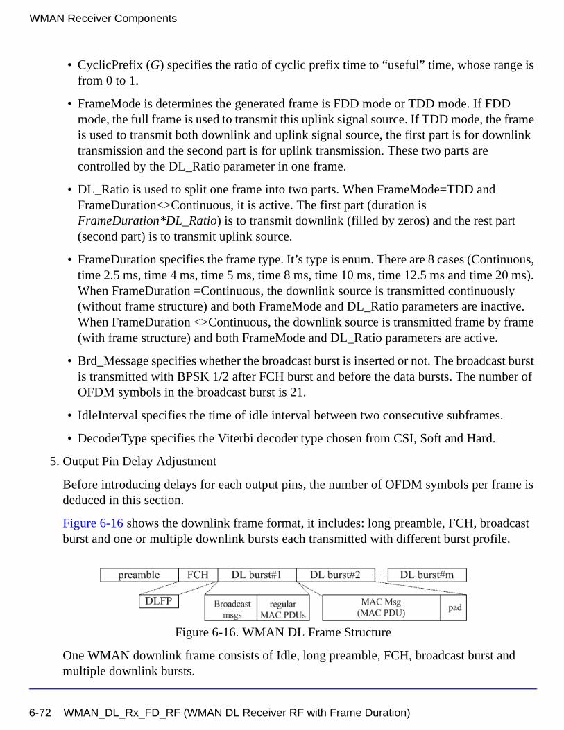
WMAN Receiver Components
• CyclicPrefix (G) specifies the ratio of cyclic prefix time to “useful” time, whose range is from 0 to 1.
• FrameMode is determines the generated frame is FDD mode or TDD mode. If FDD mode, the full frame is used to transmit this uplink signal source. If TDD mode, the frame is used to transmit both downlink and uplink signal source, the first part is for downlink transmission and the second part is for uplink transmission. These two parts are controlled by the DL_Ratio parameter in one frame.
• DL_Ratio is used to split one frame into two parts. When FrameMode=TDD and FrameDuration<>Continuous, it is active. The first part (duration is FrameDuration*DL_Ratio) is to transmit downlink (filled by zeros) and the rest part (second part) is to transmit uplink source.
• FrameDuration specifies the frame type. It’s type is enum. There are 8 cases (Continuous, time 2.5 ms, time 4 ms, time 5 ms, time 8 ms, time 10 ms, time 12.5 ms and time 20 ms). When FrameDuration =Continuous, the downlink source is transmitted continuously (without frame structure) and both FrameMode and DL_Ratio parameters are inactive. When FrameDuration <>Continuous, the downlink source is transmitted frame by frame (with frame structure) and both FrameMode and DL_Ratio parameters are active.
• Brd_Message specifies whether the broadcast burst is inserted or not. The broadcast burst is transmitted with BPSK 1/2 after FCH burst and before the data bursts. The number of OFDM symbols in the broadcast burst is 21.
• IdleInterval specifies the time of idle interval between two consecutive subframes.
• DecoderType specifies the Viterbi decoder type chosen from CSI, Soft and Hard.
5. Output Pin Delay Adjustment
Before introducing delays for each output pins, the number of OFDM symbols per frame is deduced in this section.
Figure 6-16 shows the downlink frame format, it includes: long preamble, FCH, broadcast burst and one or multiple downlink bursts each transmitted with different burst profile.
Figure 6-16. WMAN DL Frame Structure
One WMAN downlink frame consists of Idle, long preamble, FCH, broadcast burst and multiple downlink bursts.
6-72 WMAN_DL_Rx_FD_RF (WMAN DL Receiver RF with Frame Duration)
The downlink long preamble consists of two consecutive OFDM symbols.
FCH is transmitted in one OFDM symbol. The number of OFDM symbols of ith downlink burst( ) is calculated as follows:
PreamblePresent indicates whether the downlink burst starts with a short preamble or not.
Let represent the number of OFDM symbol per each preamble present. If
preamblePresent is set to 1 in the ith burst, then , otherwise, .
So the total number of OFDM symbols for the downlink frame is calculated
as follows:
is the number of OFDM symbols of the broadcast burst where it is equal to 21 when
Brd_Message is YES, and is equal to 0 when Brd_Message is NO.
The number of samples per one OFDM symbol ( ) is calculated as:
The samples of IdleInterval( ) is calculated as follows:
If FrameDuration is Continuous, the total samples of one downlink frame
is
Otherwise, if FrameDuration is set to other values (2.5 ms, 4 ms, 5 ms, 8 ms, 10 ms, 12.5 ms
or 20 ms), the total samples of one downlink frame is
NSymbol i[ ]
NSymbol i[ ] ceil DataLength i[ ] 11+( ) uncodedBlockSize R i[ ][ ]( )⁄( )=
Prml i[ ]
Prml i[ ] 1= Prml i[ ] 0=
NtotalSymbol
NtotalSymbol 2 1 NBrdcst NSymbol i[ ] Prml i[ ]+( )i 1=
NumberOfBurst
∑+ + +=
NBrdcst
SamplesOFDM
SamplesOFDM 2OversamplingOption
256× 1 G+( )×=
Nidle
Samplesidle IdleInterval 2OversamplingOption
Fs××=
SamplesFrame
SamplesFrame Samplesidle NtotalSymbol SamplesOFDM×+=
SamplesFrame
SamplesFrame Samplesidle FrameDuration Fs 2× OversamplingOption×+=
WMAN_DL_Rx_FD_RF (WMAN DL Receiver RF with Frame Duration) 6-73
WMAN Receiver Components
This model work on frame by fame. Each firing, tokens are consumed at Pin
FrameData.
For_EVM pin has one WMAN OFDM DL frame delay. This pin outputs all the number OFDM symbols except preambles. Each firing, pin For_EVM produces
tokens. Moreover, the first
output signals at the For_EVM pin are zeros.
PSDUFCS has one frame delay. This pin outputs demodulated PSDU and FCS information bits after fully decoding (de-interleaving, Viterbi decoding and De-scrambling). So, the
delay of PSDUFCS is . The first
bits at the PSDUFCS pin ares zero.
PSDU also has one frame delay. This pin outputs demodulated PSDU information bits after fully decoding (de-interleaving, Viterbi decoding and De-scrambling). So, the delay of
PSDUFCS is . The first
bits at the PSDU pin ares zero.
CIR output pin also has one frame delay. Each firing, pin CIR produces
tokens. the first output
signals at the CIR pin are zeros.
References
[1] IEEE Std 802.16-2004, Part 16: Air Interface for Fixed Broadband Wireless Access Systems, Section 8.3 WirelessMAN-OFDM PHY, October 1, 2004.
[2] IEEE P802.16-2004/Cor1/D5, Corrigendum to IEEE Standard for Local and Metropolitan Area Networks - Part 16: Air Interface for Fixed Broadband Wireless Access Systems, Sept. 2005.
SamplesFrame
200 1 NBrdcst NSymbol i[ ]i 1=
NumberOfBurst
∑+ +
×
200 1 NBrdcst NSymbol i[ ]i 1=
NumberOfBurst
∑+ +
×
8 DataLength BurstWithFEC[ ]× 80+
8 DataLength BurstWithFEC[ ]× 80+
8 DataLength BurstWithFEC[ ]×
8 DataLength× BurstWithFEC[ ]
200 1 prml i[ ]i 1=
NumberOfBurst
∑+
× 200 1 prml i[ ]i 1=
NumberOfBurst
∑+
×
6-74 WMAN_DL_Rx_FD_RF (WMAN DL Receiver RF with Frame Duration)
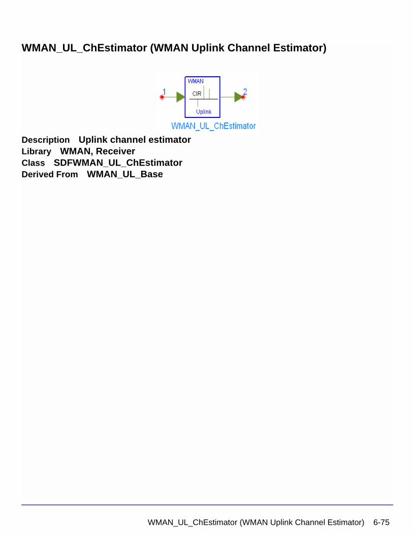
WMAN_UL_ChEstimator (WMAN Uplink Channel Estimator)
Description Uplink channel estimatorLibrary WMAN, ReceiverClass SDFWMAN_UL_ChEstimatorDerived From WMAN_UL_Base
WMAN_UL_ChEstimator (WMAN Uplink Channel Estimator) 6-75
WMAN Receiver Components
Parameters
Pin Inputs
Pin Outputs
Notes/Equations
1. This model is used to estimate WMAN uplink channel impulse response (CIR) based on the pilot channels and output the estimated channel impulse response (CIR) on the active subcarriers.
2. Each firing,
if subchannelization is not used
• tokens are consumed at pin input.
Name Description Default Type Range
NumberOfSS Number of subscribers 1 int [1, 16]
DataLength MAC PDU payload byte length of each subscriber
100 int array [1, 16383]
Rate_ID Rate ID of each subscriber 1 int array [0, 6]
Subchannelization Subchannelization or not: NO, YES
NO enum
SubchannelIndex List of each subchannel index
{8} int array [1, 15] or [17, 31]
MidambleRepetition Midamble repetition of each subscriber
0 int array [0, 3]
PrmlTimeShift Preamble time shift of each subscriber
{0} int array [0, 255]
CyclicPrefix Cyclic prefix 0.25 real [0, 1]
Pin Name Description Signal Type
1 input output signals from FFT complex
Pin Name Description Signal Type
2 Coef channel coefficient in active subcarriers complex
200 Midamble i[ ]i 1=
NumberOfSS
∑
×
6-76 WMAN_UL_ChEstimator (WMAN Uplink Channel Estimator)
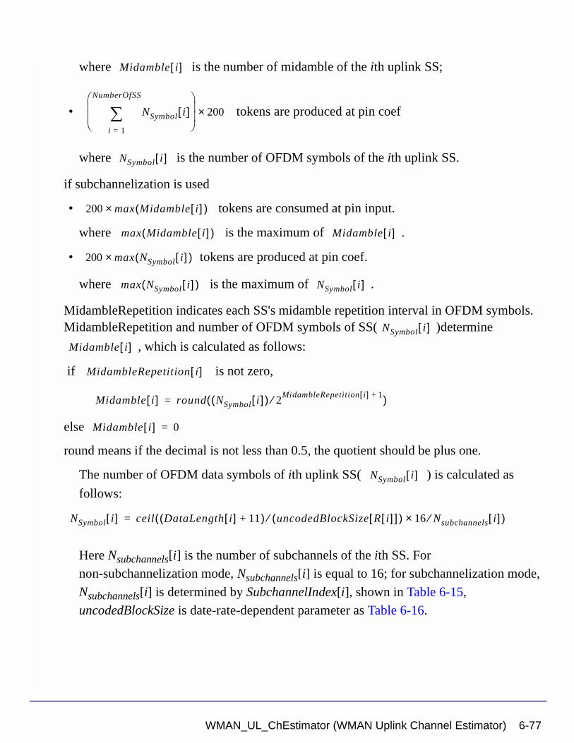
where is the number of midamble of the ith uplink SS;
• tokens are produced at pin coef
where is the number of OFDM symbols of the ith uplink SS.
if subchannelization is used
• tokens are consumed at pin input.
where is the maximum of .
• tokens are produced at pin coef.
where is the maximum of .
MidambleRepetition indicates each SS's midamble repetition interval in OFDM symbols. MidambleRepetition and number of OFDM symbols of SS( )determine
, which is calculated as follows:
if is not zero,
else
round means if the decimal is not less than 0.5, the quotient should be plus one.
The number of OFDM data symbols of ith uplink SS( ) is calculated as
follows:
Here Nsubchannels[i] is the number of subchannels of the ith SS. For
non-subchannelization mode, Nsubchannels[i] is equal to 16; for subchannelization mode,
Nsubchannels[i] is determined by SubchannelIndex[i], shown in Table 6-15,
uncodedBlockSize is date-rate-dependent parameter as Table 6-16.
Midamble i[ ]
NSymbol i[ ]i 1=
NumberOfSS
∑
200×
NSymbol i[ ]
200 max Midamble i[ ]( )×
max Midamble i[ ]( ) Midamble i[ ]
200 max NSymbol i[ ]( )×
max NSymbol i[ ]( ) NSymbol i[ ]
NSymbol i[ ]
Midamble i[ ]
MidambleRepetition i[ ]
Midamble i[ ] round NSymbol i[ ]( ) 2MidambleRepetition i[ ] 1+⁄( )=
Midamble i[ ] 0=
NSymbol i[ ]
NSymbol i[ ] ceil DataLength i[ ] 11+( ) uncodedBlockSize R i[ ][ ]( )⁄ 16 Nsubchannels⁄× i[ ]( )=
WMAN_UL_ChEstimator (WMAN Uplink Channel Estimator) 6-77
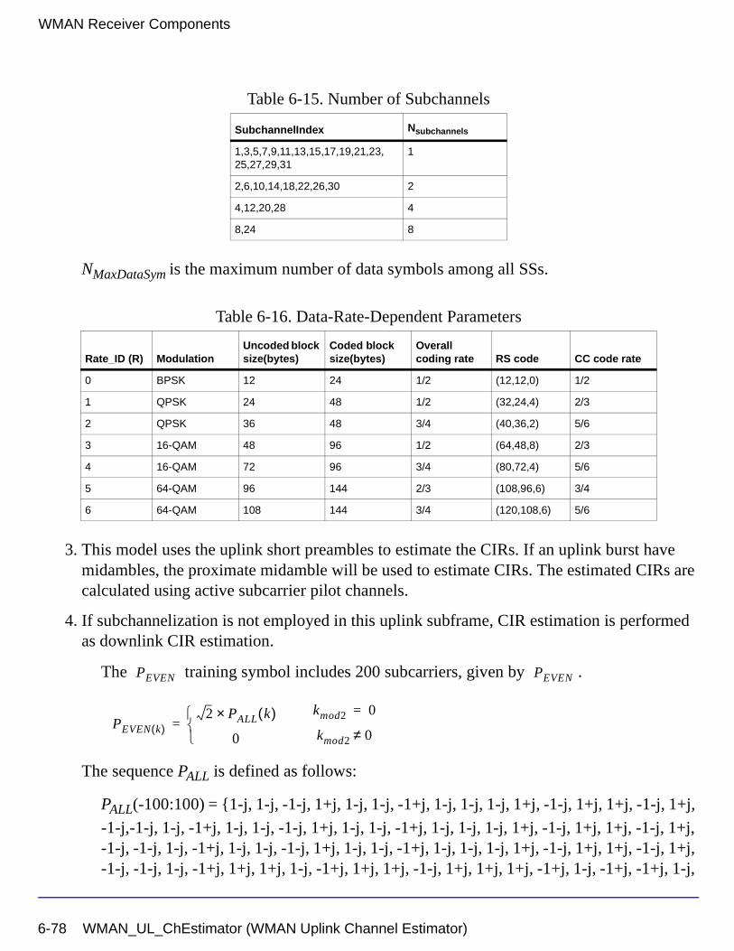
WMAN Receiver Components
NMaxDataSym is the maximum number of data symbols among all SSs.
3. This model uses the uplink short preambles to estimate the CIRs. If an uplink burst have midambles, the proximate midamble will be used to estimate CIRs. The estimated CIRs are calculated using active subcarrier pilot channels.
4. If subchannelization is not employed in this uplink subframe, CIR estimation is performed as downlink CIR estimation.
The training symbol includes 200 subcarriers, given by .
The sequence PALL is defined as follows:
PALL(-100:100) = {1-j, 1-j, -1-j, 1+j, 1-j, 1-j, -1+j, 1-j, 1-j, 1-j, 1+j, -1-j, 1+j, 1+j, -1-j, 1+j,
-1-j,-1-j, 1-j, -1+j, 1-j, 1-j, -1-j, 1+j, 1-j, 1-j, -1+j, 1-j, 1-j, 1-j, 1+j, -1-j, 1+j, 1+j, -1-j, 1+j, -1-j, -1-j, 1-j, -1+j, 1-j, 1-j, -1-j, 1+j, 1-j, 1-j, -1+j, 1-j, 1-j, 1-j, 1+j, -1-j, 1+j, 1+j, -1-j, 1+j, -1-j, -1-j, 1-j, -1+j, 1+j, 1+j, 1-j, -1+j, 1+j, 1+j, -1-j, 1+j, 1+j, 1+j, -1+j, 1-j, -1+j, -1+j, 1-j,
Table 6-15. Number of Subchannels
SubchannelIndex Nsubchannels
1,3,5,7,9,11,13,15,17,19,21,23,25,27,29,31
1
2,6,10,14,18,22,26,30 2
4,12,20,28 4
8,24 8
Table 6-16. Data-Rate-Dependent Parameters
Rate_ID (R) ModulationUncoded block size(bytes)
Coded block size(bytes)
Overall coding rate RS code CC code rate
0 BPSK 12 24 1/2 (12,12,0) 1/2
1 QPSK 24 48 1/2 (32,24,4) 2/3
2 QPSK 36 48 3/4 (40,36,2) 5/6
3 16-QAM 48 96 1/2 (64,48,8) 2/3
4 16-QAM 72 96 3/4 (80,72,4) 5/6
5 64-QAM 96 144 2/3 (108,96,6) 3/4
6 64-QAM 108 144 3/4 (120,108,6) 5/6
PEVEN PEVEN
PEVEN k( )2 PALL k( )×
0
=kmod2 0=
kmod2 0≠
6-78 WMAN_UL_ChEstimator (WMAN Uplink Channel Estimator)
-1+j, 1-j, 1-j,1+j, -1-j, -1-j, -1-j, -1+j, 1-j, -1-j, -1-j, 1+j, -1-j, -1-j, -1-j, 1-j, -1+j, 1-j, 1-j, -1+j, 1-j, -1+j,-1+j, -1-j, 1+j, 0, -1-j, 1+j, -1+j, -1+j, -1-j, 1+j, 1+j, 1+j, -1-j, 1+j, 1-j, 1-j, 1-j, -1+j, -1+j, -1+j, -1+j, 1-j, -1-j, -1-j, -1+j, 1-j, 1+j, 1+j, -1+j, 1-j, 1-j, 1-j, -1+j, 1-j, -1-j, -1-j, -1-j, 1+j, 1+j, 1+j, 1+j, -1-j, -1+j, -1+j, 1+j, -1-j, 1-j, 1-j, 1+j, -1-j, -1-j, -1-j, 1+j, -1-j, -1+j, -1+j, -1+j, 1-j, 1-j, 1-j, 1-j, -1+j, 1+j, 1+j, -1-j, 1+j, -1+j, -1+j, -1-j, 1+j, 1+j, 1+j, -1-j, 1+j, 1-j, 1-j, 1-j, -1+j, -1+j, -1+j, -1+j, 1-j, -1-j, -1-j, 1-j, -1+j, -1-j, -1-j, 1-j, -1+j, -1+j, -1+j, 1-j, -1+j,1+j, 1+j, 1+j, -1-j, -1-j, -1-j, -1-j, 1+j, 1-j, 1-j}
Set are the input signals, are the estimated CIRs.The estimated
CIR in even subcarriers can be calculated as follows:
where .
The estimated CIR in odd subcarriers is interpolated by raised cosine filter.
5. If subchannelization is employed in this uplink subframe, the preamble is referred to as the subchannelization preamble defined by . Preamble subcarriers that do not fall within
the allocated subchannels are set to zero. Although the uplink bursts occupy different subcarriers of the same OFDM symbol, its CIR will be estimated separately. The estimated CIR in allocated subcarriers can be calculated as follows:
The sequence is defined as follows:
PSUB(-100:100) = {1+j, 1+j, -1-j, 1+j, -1+j, 1+j, 1+j, 1+j, -1-j, -1-j, 1-j, -1-j, 1-j, 1+j, 1-j,
1+j,1+j, -1-j, -1-j, 1+j, 1-j, 1+j, -1-j, 1+j, 1+j, 1+j, 1+j, -1-j, 1+j, -1+j, 1+j, 1+j, 1+j, -1-j, -1-j, 1-j, -1-j, -1-j, 1+j, 1-j, 1+j, 1+j, -1-j, -1-j, 1+j, 1-j, 1+j, -1-j, 1+j, 1+j, 1+j, 1+j, -1-j, 1+j, -1+j, 1+j, 1+j, 1+j, -1-j, -1-j, 1-j, -1-j, 1-j, -1-j, -1+j, -1-j, -1-j, 1+j, 1+j, -1-j, -1+j, -1-j, 1+j, -1-j, -1-j, 1+j, 1+j, -1-j, 1+j, -1+j, 1+j, 1+j, 1+j, -1-j, -1-j, 1-j, -1-j, 1-j, -1-j, -1+j, -1-j, -1-j, 1+j, 1+j, -1-j, -1+j, -1-j, 1+j, -1-j, -1-j, 0,1+j, 1+j, -1-j, 1+j, -1+j, 1+j, 1+j, 1+j, -1-j, -1-j, 1-j, -1-j, 1-j, 1+j, 1-j, 1+j, 1+j, -1-j, -1-j, 1+j, 1-j, 1+j, -1-j, 1+j, 1+j, -1-j, -1-j, 1+j, -1-j, 1-j, -1-j, -1-j, -1-j, 1+j, 1+j, -1+j, 1+j, 1-j, -1-j, -1+j, -1-j, -1-j, 1+j, 1+j, -1-j, -1+j, -1-j, 1+j, -1-j, -1-j, -1-j, -1-j, 1+j, -1-j, 1-j, -1-j, -1-j, -1-j, 1+j, 1+j, -1+j, 1+j, -1+j, 1+j, 1-j, 1+j, 1+j, -1-j, -1-j, 1+j, 1-j, 1+j, -1-j, 1+j, 1+j, 1+j, 1+j, -1-j, 1+j, -1+j, 1+j, 1+j, 1+j, -1-j, -1-j, 1-j, -1-j, -1-j, -1-j, -1+j, -1-j, -1-j, 1+j, 1+j, -1-j, -1+j, -1-j, 1+j, -1-j, -1-j}
the unallocated subcarriers of the uplink burst will be set to zero.
x0 x1, …, x199, h0 h1, …, h199,
hi xi PEVENi⁄=
i 0 2 … 198,,,= imod2 0=
PSUB
hi xi PSUBi⁄=
PSUB
WMAN_UL_ChEstimator (WMAN Uplink Channel Estimator) 6-79
WMAN Receiver Components
References
[1] IEEE Std 802.16-2004, Part 16: Air Interface for Fixed Broadband Wireless Access Systems, Section 8.3 WirelessMAN-OFDM PHY, October 1, 2004.
[2] IEEE P802.16-2004/Cor1/D3, Corrigendum to IEEE Standard for Local and Metropolitan Area Networks - Part 16: Air Interface for Fixed Broadband Wireless Access Systems, May 2005.
6-80 WMAN_UL_ChEstimator (WMAN Uplink Channel Estimator)
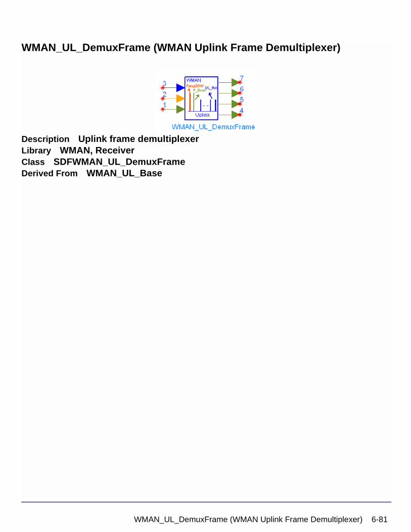
WMAN_UL_DemuxFrame (WMAN Uplink Frame Demultiplexer)
Description Uplink frame demultiplexerLibrary WMAN, ReceiverClass SDFWMAN_UL_DemuxFrameDerived From WMAN_UL_Base
WMAN_UL_DemuxFrame (WMAN Uplink Frame Demultiplexer) 6-81
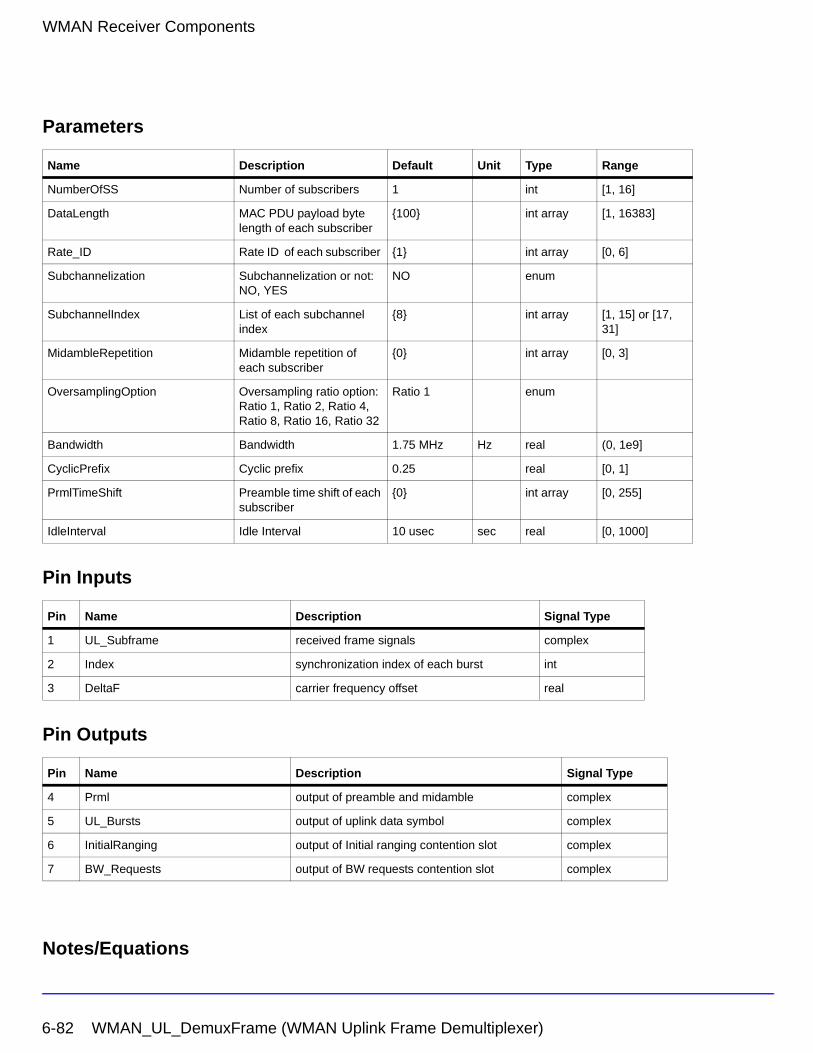
WMAN Receiver Components
Parameters
Pin Inputs
Pin Outputs
Notes/Equations
Name Description Default Unit Type Range
NumberOfSS Number of subscribers 1 int [1, 16]
DataLength MAC PDU payload byte length of each subscriber
{100} int array [1, 16383]
Rate_ID Rate ID of each subscriber {1} int array [0, 6]
Subchannelization Subchannelization or not: NO, YES
NO enum
SubchannelIndex List of each subchannel index
{8} int array [1, 15] or [17, 31]
MidambleRepetition Midamble repetition of each subscriber
{0} int array [0, 3]
OversamplingOption Oversampling ratio option: Ratio 1, Ratio 2, Ratio 4, Ratio 8, Ratio 16, Ratio 32
Ratio 1 enum
Bandwidth Bandwidth 1.75 MHz Hz real (0, 1e9]
CyclicPrefix Cyclic prefix 0.25 real [0, 1]
PrmlTimeShift Preamble time shift of each subscriber
{0} int array [0, 255]
IdleInterval Idle Interval 10 usec sec real [0, 1000]
Pin Name Description Signal Type
1 UL_Subframe received frame signals complex
2 Index synchronization index of each burst int
3 DeltaF carrier frequency offset real
Pin Name Description Signal Type
4 Prml output of preamble and midamble complex
5 UL_Bursts output of uplink data symbol complex
6 InitialRanging output of Initial ranging contention slot complex
7 BW_Requests output of BW requests contention slot complex
6-82 WMAN_UL_DemuxFrame (WMAN Uplink Frame Demultiplexer)
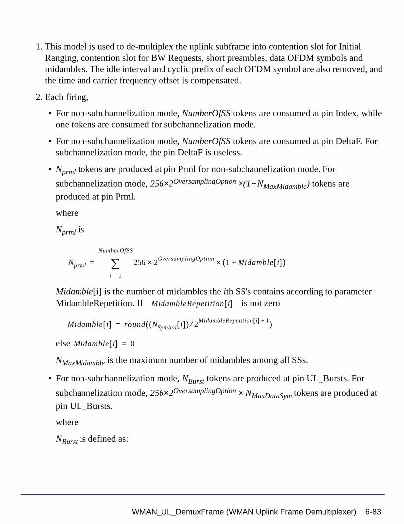
1. This model is used to de-multiplex the uplink subframe into contention slot for Initial Ranging, contention slot for BW Requests, short preambles, data OFDM symbols and midambles. The idle interval and cyclic prefix of each OFDM symbol are also removed, and the time and carrier frequency offset is compensated.
2. Each firing,
• For non-subchannelization mode, NumberOfSS tokens are consumed at pin Index, while one tokens are consumed for subchannelization mode.
• For non-subchannelization mode, NumberOfSS tokens are consumed at pin DeltaF. For subchannelization mode, the pin DeltaF is useless.
• Nprml tokens are produced at pin Prml for non-subchannelization mode. For
subchannelization mode, 256×2OversamplingOption ×(1+NMaxMidamble) tokens are
produced at pin Prml.
where
Nprml is
Midamble[i] is the number of midambles the ith SS's contains according to parameter MidambleRepetition. If is not zero
else
NMaxMidamble is the maximum number of midambles among all SSs.
• For non-subchannelization mode, NBurst tokens are produced at pin UL_Bursts. For
subchannelization mode, 256×2OversamplingOption × NMaxDataSym tokens are produced at
pin UL_Bursts.
where
NBurst is defined as:
Nprml 256 2OversamplingOption× 1 Midamble i[ ]+( )×
i 1=
NumberOfSS
∑=
MidambleRepetition i[ ]
Midamble i[ ] round NSymbol i[ ]( ) 2MidambleRepetition i[ ] 1+⁄( )=
Midamble i[ ] 0=
WMAN_UL_DemuxFrame (WMAN Uplink Frame Demultiplexer) 6-83
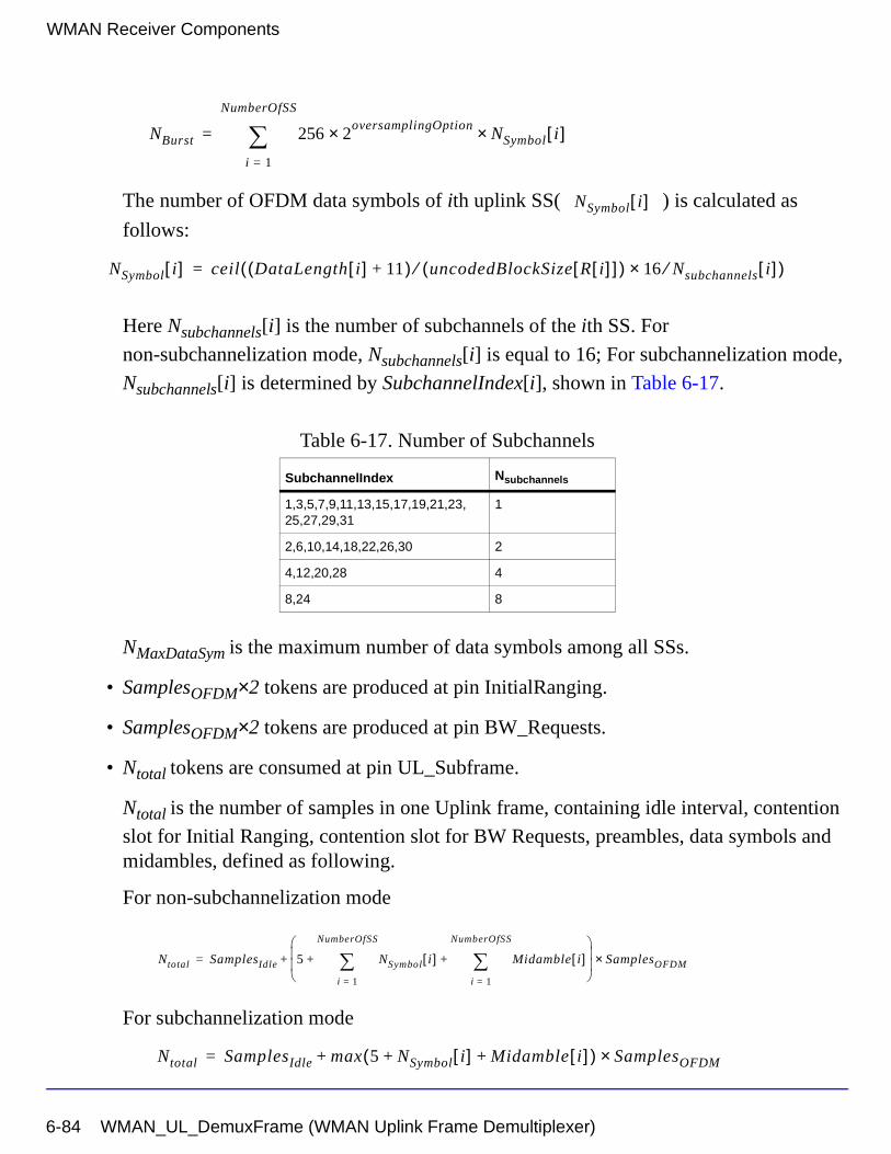
WMAN Receiver Components
The number of OFDM data symbols of ith uplink SS( ) is calculated as
follows:
Here Nsubchannels[i] is the number of subchannels of the ith SS. For
non-subchannelization mode, Nsubchannels[i] is equal to 16; For subchannelization mode,
Nsubchannels[i] is determined by SubchannelIndex[i], shown in Table 6-17.
NMaxDataSym is the maximum number of data symbols among all SSs.
• SamplesOFDM×2 tokens are produced at pin InitialRanging.
• SamplesOFDM×2 tokens are produced at pin BW_Requests.
• Ntotal tokens are consumed at pin UL_Subframe.
Ntotal is the number of samples in one Uplink frame, containing idle interval, contention
slot for Initial Ranging, contention slot for BW Requests, preambles, data symbols and midambles, defined as following.
For non-subchannelization mode
For subchannelization mode
Table 6-17. Number of Subchannels
SubchannelIndex Nsubchannels
1,3,5,7,9,11,13,15,17,19,21,23,25,27,29,31
1
2,6,10,14,18,22,26,30 2
4,12,20,28 4
8,24 8
NBurst 256 2oversamplingOption× NSymbol i[ ]×
i 1=
NumberOfSS
∑=
NSymbol i[ ]
NSymbol i[ ] ceil DataLength i[ ] 11+( ) uncodedBlockSize R i[ ][ ]( )⁄ 16 Nsubchannels⁄× i[ ]( )=
Ntotal SamplesIdle 5 NSymbol i[ ]i 1=
NumberOfSS
∑ Midamble i[ ]i 1=
NumberOfSS
∑+ +
SamplesOFDM×+=
Ntotal SamplesIdle max 5 NSymbol i[ ] Midamble i[ ]+ +( ) SamplesOFDM×+=
6-84 WMAN_UL_DemuxFrame (WMAN Uplink Frame Demultiplexer)
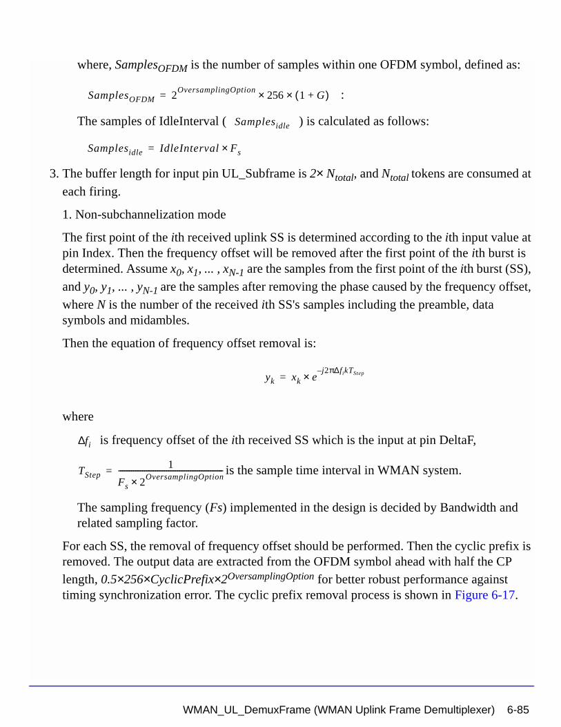
where, SamplesOFDM is the number of samples within one OFDM symbol, defined as:
:
The samples of IdleInterval ( ) is calculated as follows:
3. The buffer length for input pin UL_Subframe is 2× Ntotal, and Ntotal tokens are consumed at
each firing.
1. Non-subchannelization mode
The first point of the ith received uplink SS is determined according to the ith input value at pin Index. Then the frequency offset will be removed after the first point of the ith burst is determined. Assume x0, x1, ... , xN-1 are the samples from the first point of the ith burst (SS),
and y0, y1, ... , yN-1 are the samples after removing the phase caused by the frequency offset,
where N is the number of the received ith SS's samples including the preamble, data symbols and midambles.
Then the equation of frequency offset removal is:
where
is frequency offset of the ith received SS which is the input at pin DeltaF,
is the sample time interval in WMAN system.
The sampling frequency (Fs) implemented in the design is decided by Bandwidth and related sampling factor.
For each SS, the removal of frequency offset should be performed. Then the cyclic prefix is removed. The output data are extracted from the OFDM symbol ahead with half the CP length, 0.5×256×CyclicPrefix×2OversamplingOption for better robust performance against timing synchronization error. The cyclic prefix removal process is shown in Figure 6-17.
SamplesOFDM 2OversamplingOption
256× 1 G+( )×=
Samplesidle
Samplesidle IdleInterval Fs×=
yk xk ej2π∆fikTStep–
×=
fi∆
TStep1
Fs 2OversamplingOption×
---------------------------------------------------------=
WMAN_UL_DemuxFrame (WMAN Uplink Frame Demultiplexer) 6-85
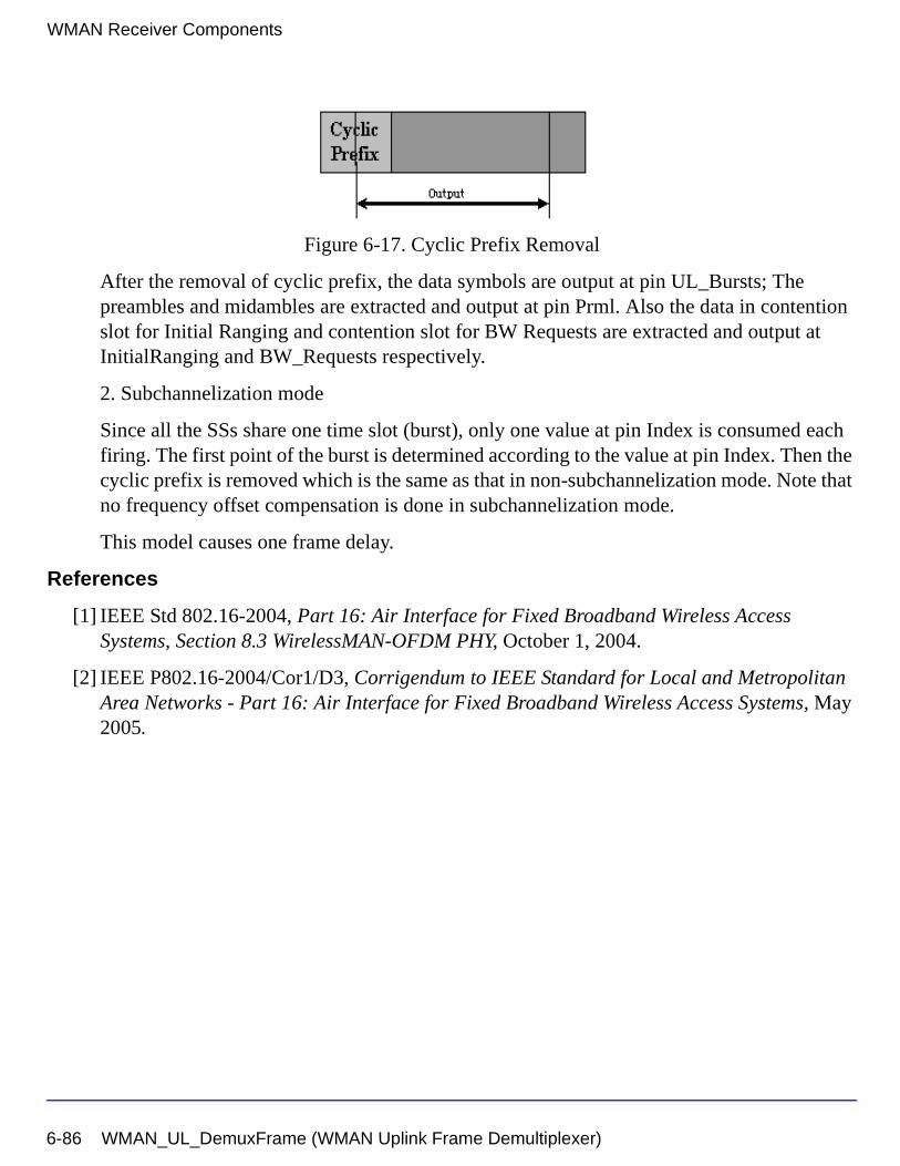
WMAN Receiver Components
Figure 6-17. Cyclic Prefix Removal
After the removal of cyclic prefix, the data symbols are output at pin UL_Bursts; The preambles and midambles are extracted and output at pin Prml. Also the data in contention slot for Initial Ranging and contention slot for BW Requests are extracted and output at InitialRanging and BW_Requests respectively.
2. Subchannelization mode
Since all the SSs share one time slot (burst), only one value at pin Index is consumed each firing. The first point of the burst is determined according to the value at pin Index. Then the cyclic prefix is removed which is the same as that in non-subchannelization mode. Note that no frequency offset compensation is done in subchannelization mode.
This model causes one frame delay.
References
[1] IEEE Std 802.16-2004, Part 16: Air Interface for Fixed Broadband Wireless Access Systems, Section 8.3 WirelessMAN-OFDM PHY, October 1, 2004.
[2] IEEE P802.16-2004/Cor1/D3, Corrigendum to IEEE Standard for Local and Metropolitan Area Networks - Part 16: Air Interface for Fixed Broadband Wireless Access Systems, May 2005.
6-86 WMAN_UL_DemuxFrame (WMAN Uplink Frame Demultiplexer)
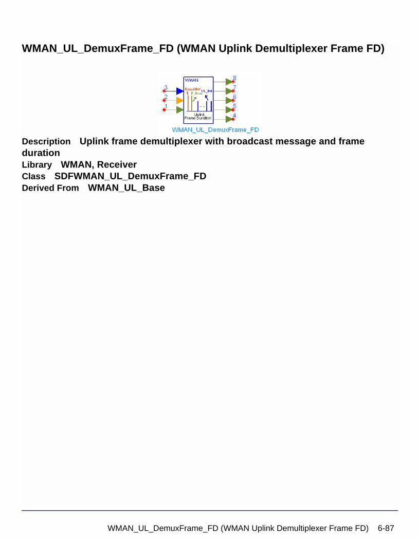
WMAN_UL_DemuxFrame_FD (WMAN Uplink Demultiplexer Frame FD)
Description Uplink frame demultiplexer with broadcast message and frame durationLibrary WMAN, ReceiverClass SDFWMAN_UL_DemuxFrame_FDDerived From WMAN_UL_Base
WMAN_UL_DemuxFrame_FD (WMAN Uplink Demultiplexer Frame FD) 6-87
WMAN Receiver Components
Parameters
Pin Inputs
Pin Outputs
Name Description Default Unit Type Range
NumberOfSS Number of subscribers 1 int [1, 16]
DataLength MAC PDU payload byte length of each subscriber
{100} int array [1, 16383]
Rate_ID Rate ID of each subscriber {1} int array [0, 6]
Subchannelization Subchannelization or not: NO, YES
NO enum
SubchannelIndex List of each subchannel index
{8} int array [1, 15] or [17, 31]
MidambleRepetition Midamble repetition of each subscriber
{0} int array [0, 3]
OversamplingOption Oversampling ratio option: Ratio 1, Ratio 2, Ratio 4, Ratio 8, Ratio 16, Ratio 32
Ratio 1 enum
Bandwidth Bandwidth 1.75 MHz Hz real (0, 1e9]
CyclicPrefix Cyclic prefix 0.25 real [0, 1]
PrmlTimeShift Preamble time shift of each subscriber
{0} int array [0, 255]
IdleInterval Idle Interval 10 usec sec real [0, 1000]
FrameMode Frame mode: FDD, TDD FDD enum
DL_Ratio Downlink ratio 0.5 real [0.01, 0.99]
FrameDuration Frame duration: Continuous, time 2.5 ms, time 4 ms, time 5 ms, time 8 ms, time 10 ms, time 12.5 ms, time 20 ms
Continuous enum
Pin Name Description Signal Type
1 UL_Subframe received frame signals complex
2 Index synchronization index of each burst int
3 DeltaF carrier frequency offset real
Pin Name Description Signal Type
4 Prml output of preamble and midamble complex
5 UL_Bursts output of uplink data symbol complex
6-88 WMAN_UL_DemuxFrame_FD (WMAN Uplink Demultiplexer Frame FD)
Notes/Equations
1. This model is used to de-multiplex the uplink subframe into contention slot for Initial Ranging, contention slot for BW Requests, short preambles, data OFDM symbols and midambles. The idle interval and cyclic prefix of each OFDM symbol are also removed, and the carrier frequency offset is compensated according to the value achieved at pin DeltaF.
2. Each firing,
• For non-subchannelization mode, NumberOfSS tokens are consumed at pin Index, while one tokens are consumed for subchannelization mode.
• For non-subchannelization mode, NumberOfSS tokens are consumed at pin DeltaF. For subchannelization mode, the pin DeltaF is useless.
• Nprml tokens are produced at pin Prml for non-subchannelization mode. For
subchannelization mode, 256×2OversamplingOption ×(1+NMaxMidamble) tokens are
produced at pin Prml.
where
Nprml is
Midamble[i] is the number of midambles the ith SS's contains according to parameter
MidambleRepetition. If is not zero
else
6 InitialRanging output of Initial ranging contention slot complex
7 BW_Requests output of BW requests contention slot complex
8 all_bursts output all the preamble and data sequences complex
Pin Name Description Signal Type
Nprml 256 2OversamplingOption× 1 Midamble i[ ]+( )×
i 1=
NumberOfSS
∑=
Midamble i[ ] round NSymbol i[ ]( ) 2MidambleRepetition i[ ] 1+⁄( )=
MidambleRepetition i[ ]
Midamble i[ ] 0=
WMAN_UL_DemuxFrame_FD (WMAN Uplink Demultiplexer Frame FD) 6-89

WMAN Receiver Components
NMaxMidamble is the maximum number of midambles among all SSs.
• For non-subchannelization mode, NBurst tokens are produced at pin UL_Bursts. For
subchannelization mode, 256×2OversamplingOption × ΝΜαξ∆αταΣψµ tokens are produced at pin UL_Bursts.
where
NBurst is defined as:
The number of OFDM data symbols of ith uplink SS( ) is calculated as follows:
Here Nsubchannels is the number of subchannels. For non-subchannelization mode,
Nsubchannels is equal to 16; For subchannelization mode, Nsubchannels is determined by
SubchannelIndex, shown in Table 6-18.
ΝΜαξ∆αταΣψµ is the maximum number of data symbols among all SSs.
• SamplesOFDM×2 tokens are produced at pin InitialRanging.
• SamplesOFDM×2 tokens are produced at pin BW_Requests.
• Nallbursts tokens are output at pin all_bursts.
The Nallbursts is defined as follows:
Table 6-18. Number of Subchannels
Nsubchannels SubchannelIndex
1 1,3,5,7,9,11,13,15,17,19,21,23,25,27,29,31
2 2,6,10,14,18,22,26,30
4 4,12,20,28
8 8,24
NBurst 256 2oversamplingOption× NSymbol i[ ]×
i 1=
NumberOfSS
∑=
NSymbol i[ ]
NSymbol i[ ] ceil DataLength i[ ] 11+( ) uncodedBlockSize R i[ ][ ]( )⁄ 16 Nsubchannels⁄×( )=
6-90 WMAN_UL_DemuxFrame_FD (WMAN Uplink Demultiplexer Frame FD)
For non-subchannelization mode
For subchannelization mode
where, SamplesOFDM is the number of one OFDM symbol data, defined as:
• Ntotal tokens are consumed at pin UL_Subframe.
Ntotal is the number of samples in one Uplink frame, containing idle interval, contention
slot for Initial Ranging, contention slot for BW Requests, preambles, data symbols and midambles, defined as following.
For non-subchannelization mode when FrameDuration=Continuous
For subchannelization mode when FrameDuration=Continuous
When FrameDuration<>Continuous, the total number of samples per one frame is
where, SamplesOFDM is the number of one OFDM symbol data, defined as:
Nallbursts 1 NSymbol i[ ]i 1=
NumberOfSS
∑ Midamble i[ ]i 1=
NumberOfSS
∑+ +
SamplesOFDM×=
Nallbursts max 1 NSymbol i[ ] Midamble i[ ]+ +( ) SamplesOFDM×=
SamplesOFDM 2OversamplingOption
256× 1 G+( )×=
Ntotal SamplesIdle 5 NSymbol i[ ]i 1=
NumberOfSS
∑ Midamble i[ ]i 1=
NumberOfSS
∑+ +
SamplesOFDM×+=
Ntotal SamplesIdle max 5 NSymbol i[ ] Midamble i[ ]+ +( ) SamplesOFDM×+=
Ntotal SamplesIdle FrameDuration Fs× 2OversamplingOption×+=
SamplesOFDM 2OversamplingOption
256× 1 G+( )×=
WMAN_UL_DemuxFrame_FD (WMAN Uplink Demultiplexer Frame FD) 6-91
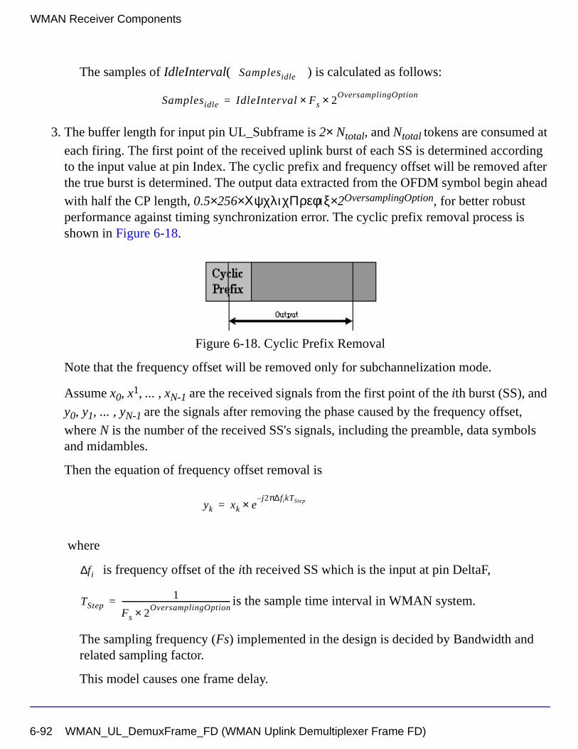
WMAN Receiver Components
The samples of IdleInterval( ) is calculated as follows:
3. The buffer length for input pin UL_Subframe is 2× Ntotal, and Ntotal tokens are consumed at
each firing. The first point of the received uplink burst of each SS is determined according to the input value at pin Index. The cyclic prefix and frequency offset will be removed after the true burst is determined. The output data extracted from the OFDM symbol begin ahead with half the CP length, 0.5×256×ΧψχλιχΠρεφιξ× 2OversamplingOption, for better robust performance against timing synchronization error. The cyclic prefix removal process is shown in Figure 6-18.
Figure 6-18. Cyclic Prefix Removal
Note that the frequency offset will be removed only for subchannelization mode.
Assume x0, x1, ... , xN-1 are the received signals from the first point of the ith burst (SS), and
y0, y1, ... , yN-1 are the signals after removing the phase caused by the frequency offset,
where N is the number of the received SS's signals, including the preamble, data symbols and midambles.
Then the equation of frequency offset removal is
where
is frequency offset of the ith received SS which is the input at pin DeltaF,
is the sample time interval in WMAN system.
The sampling frequency (Fs) implemented in the design is decided by Bandwidth and related sampling factor.
This model causes one frame delay.
Samplesidle
Samplesidle IdleInterval Fs× 2OversamplingOption×=
yk xk ej2π∆fikTStep–
×=
fi∆
TStep1
Fs 2OversamplingOption×
---------------------------------------------------------=
6-92 WMAN_UL_DemuxFrame_FD (WMAN Uplink Demultiplexer Frame FD)
References
[1] IEEE Std 802.16-2004, Part 16: Air Interface for Fixed Broadband Wireless Access Systems, Section 8.3 WirelessMAN-OFDM PHY, October 1, 2004.
[2] IEEE P802.16-2004/Cor1/D5, Corrigendum to IEEE Standard for Local and Metropolitan Area Networks - Part 16: Air Interface for Fixed Broadband Wireless Access Systems, Sept. 2005.
WMAN_UL_DemuxFrame_FD (WMAN Uplink Demultiplexer Frame FD) 6-93
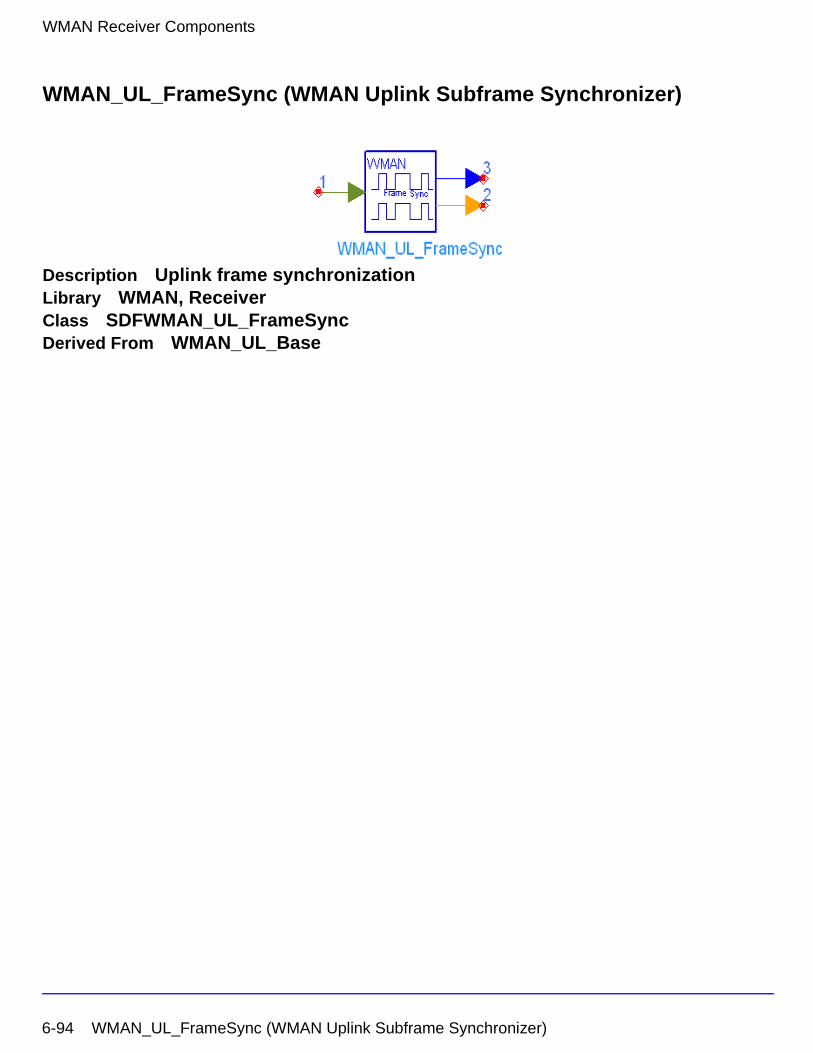
WMAN Receiver Components
WMAN_UL_FrameSync (WMAN Uplink Subframe Synchronizer)
Description Uplink frame synchronizationLibrary WMAN, ReceiverClass SDFWMAN_UL_FrameSyncDerived From WMAN_UL_Base
6-94 WMAN_UL_FrameSync (WMAN Uplink Subframe Synchronizer)
Parameters
Pin Inputs
Pin Outputs
Name Description Default Unit Type Range
NumberOfSS Number of subscribers 1 int [1, 16]
DataLength MAC PDU payload byte length of each subscriber
{100} int array [1, 16383]
Rate_ID Rate ID of each subscriber {1} int array [0, 6]
Subchannelization Subchannelization or not: NO, YES
NO enum
SubchannelIndex List of each subchannel index
{8} int array [1, 15] or [17, 31]
MidambleRepetition Midamble repetition of each subscriber
{0} int array [0, 3]
OversamplingOption Oversampling ratio option: Ratio 1, Ratio 2, Ratio 4, Ratio 8, Ratio 16, Ratio 32
Ratio 1 enum
Bandwidth Bandwidth 1.75 MHz Hz real (0, 1e9]
CyclicPrefix Cyclic prefix 0.25 real [0, 1]
PrmlTimeShift Preamble time shift of each subscribe
{0} int array [0, 255]
IdleInterval Idle Interval 10 usec sec real [0, 1000]
FrameMode Frame mode: FDD, TDD FDD enum
DL_Ratio Downlink ratio 0.5 real [0.01, 0.99]
FrameDuration Frame duration: Continuous, time 2.5 ms, time 4 ms, time 5 ms, time 8 ms, time 10 ms, time 12.5 ms, time 20 ms
Continuous enum
Pin Name Description Signal Type
1 input uplink frame complex
Pin Name Description Signal Type
2 index synchronization burst start position int
3 corr correlation result real
WMAN_UL_FrameSync (WMAN Uplink Subframe Synchronizer) 6-95
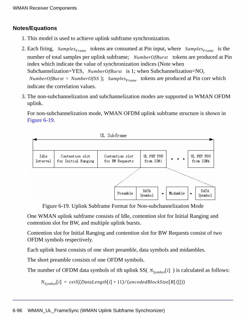
WMAN Receiver Components
Notes/Equations
1. This model is used to achieve uplink subframe synchronization.
2. Each firing, tokens are consumed at Pin input, where is the
number of total samples per uplink subframe; tokens are produced at Pin index which indicate the value of synchronization indices (Note when Subchannelization=YES, is 1; when Subchannelization=NO,
); tokens are produced at Pin corr which
indicate the correlation values.
3. The non-subchannelization and subchannelization modes are supported in WMAN OFDM uplink.
For non-subchannelization mode, WMAN OFDM uplink subframe structure is shown in Figure 6-19.
Figure 6-19. Uplink Subframe Format for Non-subchannelization Mode
One WMAN uplink subframe consists of Idle, contention slot for Initial Ranging and contention slot for BW, and multiple uplink bursts.
Contention slot for Initial Ranging and contention slot for BW Requests consist of two OFDM symbols respectively.
Each uplink burst consists of one short preamble, data symbols and midambles.
The short preamble consists of one OFDM symbols.
The number of OFDM data symbols of ith uplink SS( ) is calculated as follows:
SamplesFrame SamplesFrame
NumberOfBurst
NumberOfBurst
NumberOfBurst NumberOfSS= SamplesFrame
NSymbol i[ ]
NSymbol i[ ] ceil DataLength i[ ] 11+( ) uncodedBlockSize R i[ ][ ]( )⁄( )=
6-96 WMAN_UL_FrameSync (WMAN Uplink Subframe Synchronizer)
MidambleRepetition indicates each SS's midamble repetition interval in OFDM symbols. Let represent the number of midamble symbols in ith uplink burst,
if is not zero,
else,
So the total number of OFDM symbols for the uplink frame is calculated as
follows:
The number of samples per one OFDM symbol ( ) is calculated as:
where G is the CyclicPrefix.
The samples of IdleInterval( ) is calculated as follows:
When FrameDuration=Continuous, the total samples of one uplink subframe
is
When FrameDuration<>Continuous, the total samples of one uplink subframe
is
Midamble i[ ]
MidambleRepetition i[ ]
Midamble i[ ] round NSymbol i[ ]( ) 2MidambleRepetition i[ ] 1+⁄( )=
Midamble i[ ] 0=
NtotalSymbol
NtotalSymbol 2 2 NSymbol i[ ] 1 Midamble i[ ]+ +( )i 1=
NumberOfSS
∑+ +=
SamplesOFDM
SamplesOFDM 2OversamplingOption
256× 1 G+( )×=
Samplesidle
Samplesidle IdleInterval Fs× 2OversamplingOption×=
SamplesFrame
SamplesFrame Samplesidle NtotalSymbol SamplesOFDM×+=
SamplesFrame
SamplesFrame Samplesidle FrameDuration Fs 2OversamplingOption××+=
WMAN_UL_FrameSync (WMAN Uplink Subframe Synchronizer) 6-97
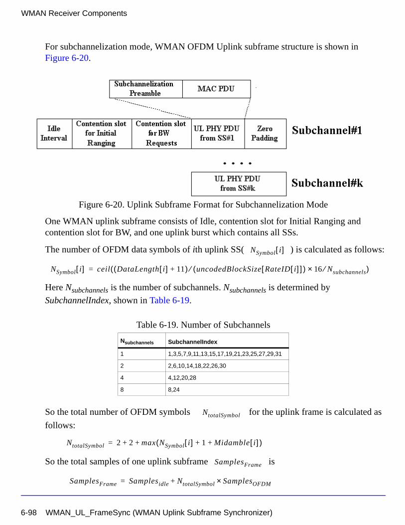
WMAN Receiver Components
For subchannelization mode, WMAN OFDM Uplink subframe structure is shown in Figure 6-20.
Figure 6-20. Uplink Subframe Format for Subchannelization Mode
One WMAN uplink subframe consists of Idle, contention slot for Initial Ranging and contention slot for BW, and one uplink burst which contains all SSs.
The number of OFDM data symbols of ith uplink SS( ) is calculated as follows:
Here Nsubchannels is the number of subchannels. Nsubchannels is determined by
SubchannelIndex, shown in Table 6-19.
So the total number of OFDM symbols for the uplink frame is calculated as
follows:
So the total samples of one uplink subframe is
Table 6-19. Number of Subchannels
Nsubchannels SubchannelIndex
1 1,3,5,7,9,11,13,15,17,19,21,23,25,27,29,31
2 2,6,10,14,18,22,26,30
4 4,12,20,28
8 8,24
NSymbol i[ ]
NSymbol i[ ] ceil DataLength i[ ] 11+( ) uncodedBlockSize RateID i[ ][ ]( )⁄ 16 Nsubchannels⁄×( )=
NtotalSymbol
NtotalSymbol 2 2 max NSymbol i[ ] 1 Midamble i[ ]+ +( )+ +=
SamplesFrame
SamplesFrame Samplesidle NtotalSymbol SamplesOFDM×+=
6-98 WMAN_UL_FrameSync (WMAN Uplink Subframe Synchronizer)
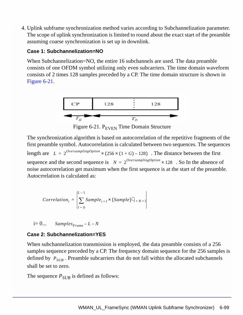
4. Uplink subframe synchronization method varies according to Subchannelization parameter. The scope of uplink synchronization is limited to round about the exact start of the preamble assuming coarse synchronization is set up in downlink.
Case 1: Subchannelization=NO
When Subchannelization=NO, the entire 16 subchannels are used. The data preamble consists of one OFDM symbol utilizing only even subcarriers. The time domain waveform consists of 2 times 128 samples preceded by a CP. The time domain structure is shown in Figure 6-21.
Figure 6-21. PEVEN Time Domain Structure
The synchronization algorithm is based on autocorrelation of the repetitive fragments of the first preamble symbol. Autocorrelation is calculated between two sequences. The sequences
length are . The distance between the first
sequence and the second sequence is . So In the absence of noise autocorrelation get maximum when the first sequence is at the start of the preamble. Autocrrelation is calculated as:
i= 0...
Case 2: Subchannelization=YES
When subchannelization transmission is employed, the data preamble consists of a 256 samples sequence preceded by a CP. The frequency domain sequence for the 256 samples is defined by . Preamble subcarriers that do not fall within the allocated subchannels
shall be set to zero.
The sequence PSUB is defined as follows:
L 2OversamplingOption
256 1 G+( )× 128–( )×=
N 2OversamplingOption
128×=
Correlationi Samplei l+ Sample( )∗ i N l+ +×l 0=
L 1–
∑=
SamplesFrame L– N–
PSUB
WMAN_UL_FrameSync (WMAN Uplink Subframe Synchronizer) 6-99
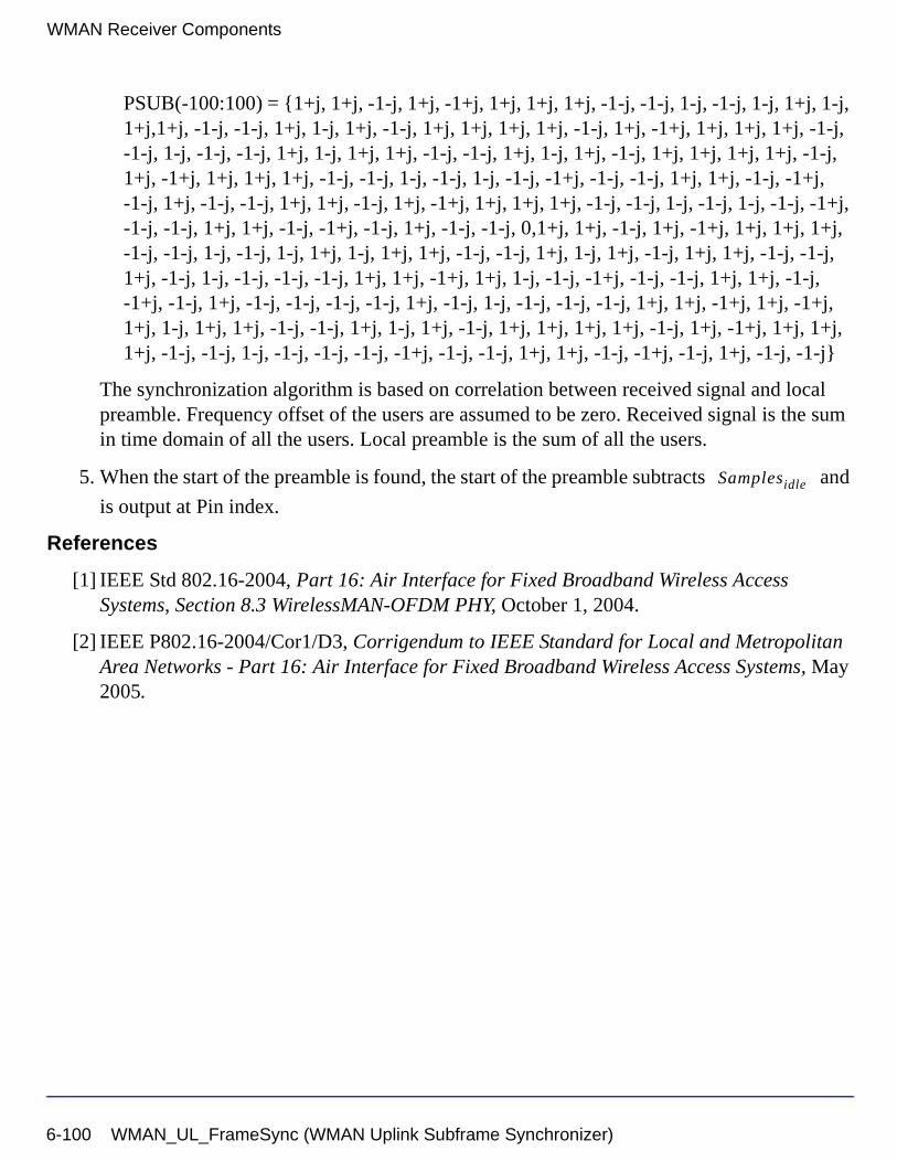
WMAN Receiver Components
PSUB(-100:100) = {1+j, 1+j, -1-j, 1+j, -1+j, 1+j, 1+j, 1+j, -1-j, -1-j, 1-j, -1-j, 1-j, 1+j, 1-j, 1+j,1+j, -1-j, -1-j, 1+j, 1-j, 1+j, -1-j, 1+j, 1+j, 1+j, 1+j, -1-j, 1+j, -1+j, 1+j, 1+j, 1+j, -1-j, -1-j, 1-j, -1-j, -1-j, 1+j, 1-j, 1+j, 1+j, -1-j, -1-j, 1+j, 1-j, 1+j, -1-j, 1+j, 1+j, 1+j, 1+j, -1-j, 1+j, -1+j, 1+j, 1+j, 1+j, -1-j, -1-j, 1-j, -1-j, 1-j, -1-j, -1+j, -1-j, -1-j, 1+j, 1+j, -1-j, -1+j, -1-j, 1+j, -1-j, -1-j, 1+j, 1+j, -1-j, 1+j, -1+j, 1+j, 1+j, 1+j, -1-j, -1-j, 1-j, -1-j, 1-j, -1-j, -1+j, -1-j, -1-j, 1+j, 1+j, -1-j, -1+j, -1-j, 1+j, -1-j, -1-j, 0,1+j, 1+j, -1-j, 1+j, -1+j, 1+j, 1+j, 1+j, -1-j, -1-j, 1-j, -1-j, 1-j, 1+j, 1-j, 1+j, 1+j, -1-j, -1-j, 1+j, 1-j, 1+j, -1-j, 1+j, 1+j, -1-j, -1-j, 1+j, -1-j, 1-j, -1-j, -1-j, -1-j, 1+j, 1+j, -1+j, 1+j, 1-j, -1-j, -1+j, -1-j, -1-j, 1+j, 1+j, -1-j, -1+j, -1-j, 1+j, -1-j, -1-j, -1-j, -1-j, 1+j, -1-j, 1-j, -1-j, -1-j, -1-j, 1+j, 1+j, -1+j, 1+j, -1+j, 1+j, 1-j, 1+j, 1+j, -1-j, -1-j, 1+j, 1-j, 1+j, -1-j, 1+j, 1+j, 1+j, 1+j, -1-j, 1+j, -1+j, 1+j, 1+j, 1+j, -1-j, -1-j, 1-j, -1-j, -1-j, -1-j, -1+j, -1-j, -1-j, 1+j, 1+j, -1-j, -1+j, -1-j, 1+j, -1-j, -1-j}
The synchronization algorithm is based on correlation between received signal and local preamble. Frequency offset of the users are assumed to be zero. Received signal is the sum in time domain of all the users. Local preamble is the sum of all the users.
5. When the start of the preamble is found, the start of the preamble subtracts and
is output at Pin index.
References
[1] IEEE Std 802.16-2004, Part 16: Air Interface for Fixed Broadband Wireless Access Systems, Section 8.3 WirelessMAN-OFDM PHY, October 1, 2004.
[2] IEEE P802.16-2004/Cor1/D3, Corrigendum to IEEE Standard for Local and Metropolitan Area Networks - Part 16: Air Interface for Fixed Broadband Wireless Access Systems, May 2005.
Samplesidle
6-100 WMAN_UL_FrameSync (WMAN Uplink Subframe Synchronizer)
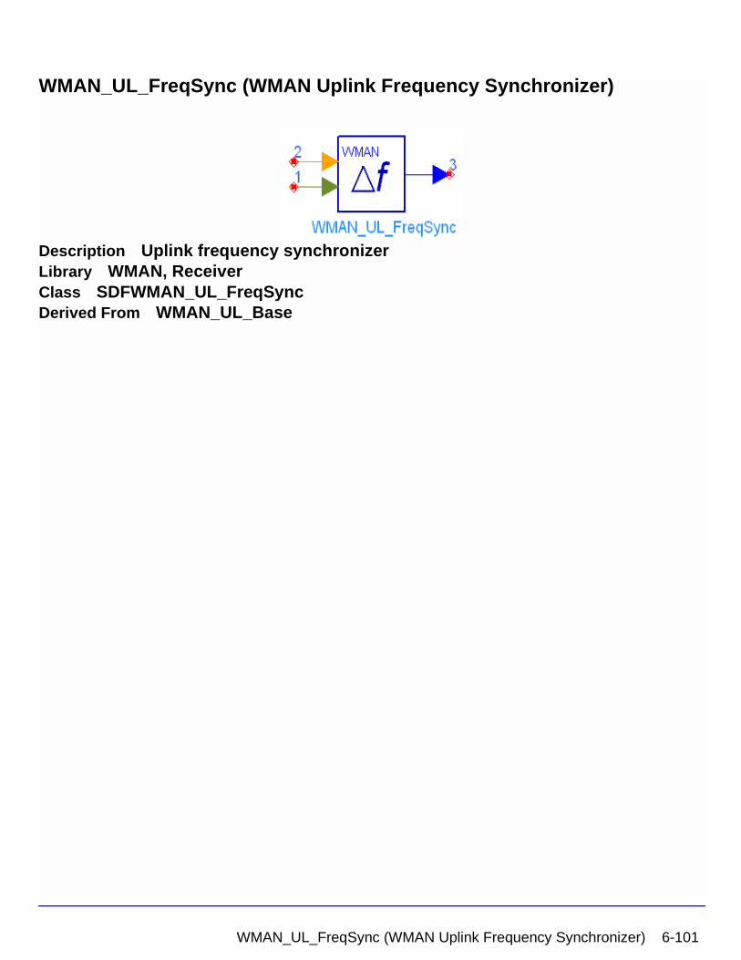
WMAN_UL_FreqSync (WMAN Uplink Frequency Synchronizer)
Description Uplink frequency synchronizerLibrary WMAN, ReceiverClass SDFWMAN_UL_FreqSyncDerived From WMAN_UL_Base
WMAN_UL_FreqSync (WMAN Uplink Frequency Synchronizer) 6-101
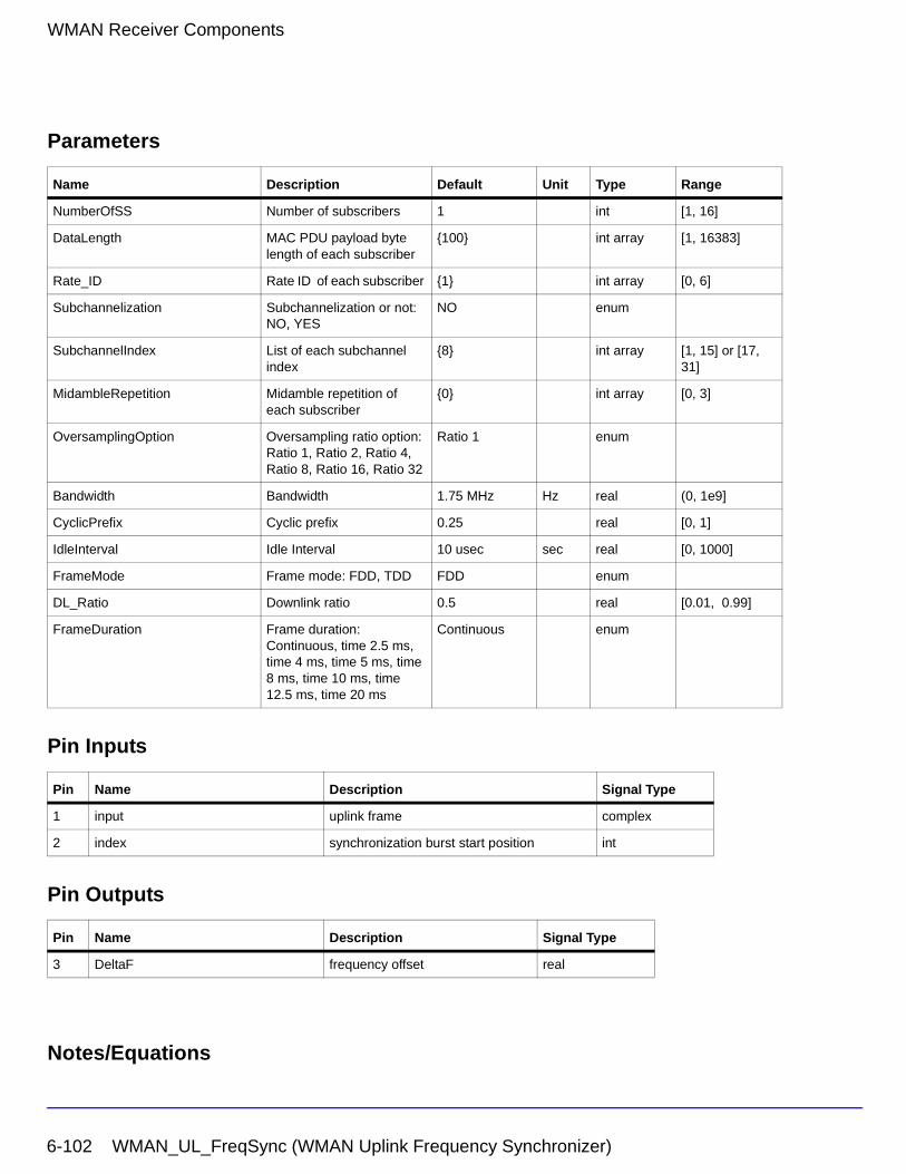
WMAN Receiver Components
Parameters
Pin Inputs
Pin Outputs
Notes/Equations
Name Description Default Unit Type Range
NumberOfSS Number of subscribers 1 int [1, 16]
DataLength MAC PDU payload byte length of each subscriber
{100} int array [1, 16383]
Rate_ID Rate ID of each subscriber {1} int array [0, 6]
Subchannelization Subchannelization or not: NO, YES
NO enum
SubchannelIndex List of each subchannel index
{8} int array [1, 15] or [17, 31]
MidambleRepetition Midamble repetition of each subscriber
{0} int array [0, 3]
OversamplingOption Oversampling ratio option: Ratio 1, Ratio 2, Ratio 4, Ratio 8, Ratio 16, Ratio 32
Ratio 1 enum
Bandwidth Bandwidth 1.75 MHz Hz real (0, 1e9]
CyclicPrefix Cyclic prefix 0.25 real [0, 1]
IdleInterval Idle Interval 10 usec sec real [0, 1000]
FrameMode Frame mode: FDD, TDD FDD enum
DL_Ratio Downlink ratio 0.5 real [0.01, 0.99]
FrameDuration Frame duration: Continuous, time 2.5 ms, time 4 ms, time 5 ms, time 8 ms, time 10 ms, time 12.5 ms, time 20 ms
Continuous enum
Pin Name Description Signal Type
1 input uplink frame complex
2 index synchronization burst start position int
Pin Name Description Signal Type
3 DeltaF frequency offset real
6-102 WMAN_UL_FreqSync (WMAN Uplink Frequency Synchronizer)
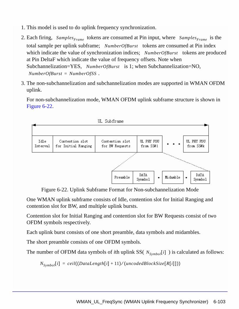
1. This model is used to do uplink frequency synchronization.
2. Each firing, tokens are consumed at Pin input, where is the
total sample per uplink subframe; tokens are consumed at Pin index which indicate the value of synchronization indices; tokens are produced at Pin DeltaF which indicate the value of frequency offsets. Note when Subchannelization=YES, is 1; when Subchannelization=NO,
.
3. The non-subchannelization and subchannelization modes are supported in WMAN OFDM uplink.
For non-subchannelization mode, WMAN OFDM uplink subframe structure is shown in Figure 6-22.
Figure 6-22. Uplink Subframe Format for Non-subchannelization Mode
One WMAN uplink subframe consists of Idle, contention slot for Initial Ranging and contention slot for BW, and multiple uplink bursts.
Contention slot for Initial Ranging and contention slot for BW Requests consist of two OFDM symbols respectively.
Each uplink burst consists of one short preamble, data symbols and midambles.
The short preamble consists of one OFDM symbols.
The number of OFDM data symbols of ith uplink SS( ) is calculated as follows:
SamplesFrame SamplesFrame
NumberOfBurst
NumberOfBurst
NumberOfBurst
NumberOfBurst NumberOfSS=
NSymbol i[ ]
NSymbol i[ ] ceil DataLength i[ ] 11+( ) uncodedBlockSize R i[ ][ ]( )⁄( )=
WMAN_UL_FreqSync (WMAN Uplink Frequency Synchronizer) 6-103
WMAN Receiver Components
MidambleRepetition indicates each SS's midamble repetition interval in OFDM symbols. Let represent the number of midamble symbols in ith uplink burst, if
is not zero,
else,
So the total number of OFDM symbols for the uplink frame is calculated as
follows:
The number of samples per one OFDM symbol ( ) is calculated as:
where G is the CyclicPrefix.
The samples of IdleInterval( ) is calculated as follows:
When FrameDuration=Continuous, the total samples of one uplink subframe
is
When FrameDuration<>Continuous, the total samples of one uplink subframe
is
For subchannelization mode, WMAN OFDM Uplink subframe structure is shown in Figure 6-23.
Midamble i[ ]MidambleRepetition i[ ]
Midamble i[ ] round NSymbol i[ ]( ) 2MidambleRepetition i[ ] 1+⁄( )=
Midamble i[ ] 0=
NtotalSymbol
NtotalSymbol 2 2 NSymbol i[ ] 1 Midamble i[ ]+ +( )i 1=
NumberOfSS
∑+ +=
SamplesOFDM
SamplesOFDM 2OversamplingOption
256× 1 G+( )×=
Samplesidle
Samplesidle IdleInterval Fs× 2OversamplingOption×=
SamplesFrame
SamplesFrame Samplesidle NtotalSymbol SamplesOFDM×+=
SamplesFrame
SamplesFrame Samplesidle FrameDuration Fs 2OversamplingOption××+=
6-104 WMAN_UL_FreqSync (WMAN Uplink Frequency Synchronizer)
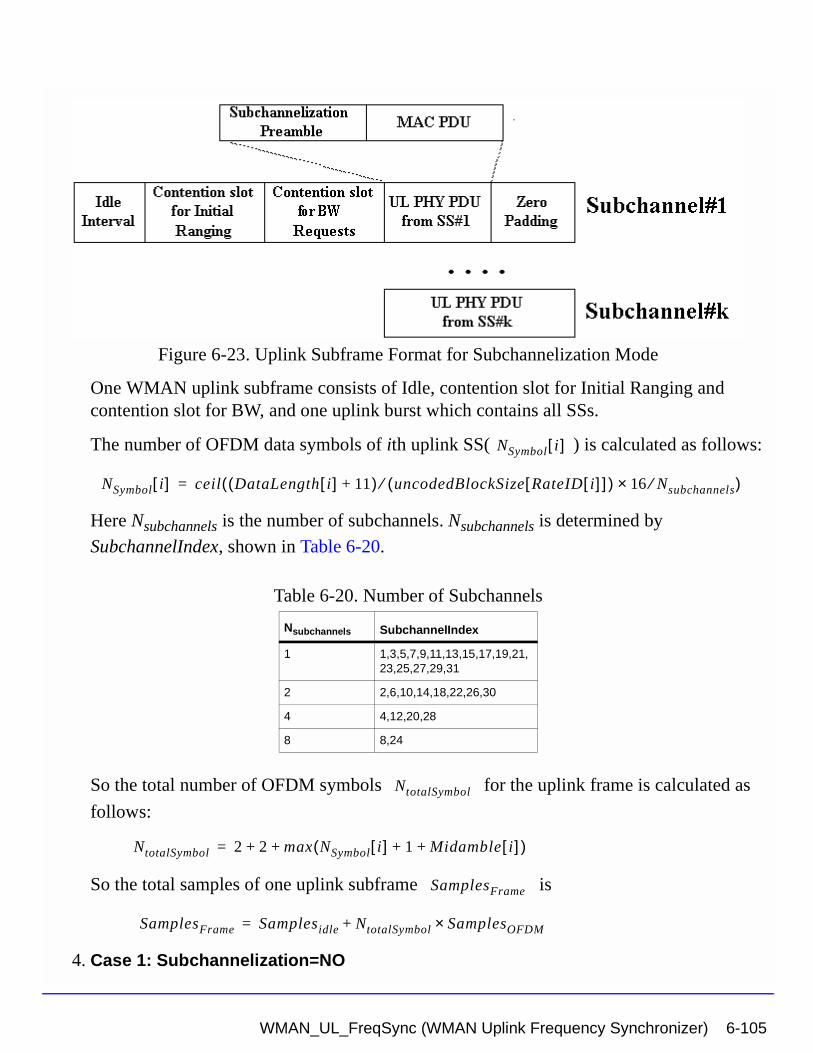
Figure 6-23. Uplink Subframe Format for Subchannelization Mode
One WMAN uplink subframe consists of Idle, contention slot for Initial Ranging and contention slot for BW, and one uplink burst which contains all SSs.
The number of OFDM data symbols of ith uplink SS( ) is calculated as follows:
Here Nsubchannels is the number of subchannels. Nsubchannels is determined by
SubchannelIndex, shown in Table 6-20.
So the total number of OFDM symbols for the uplink frame is calculated as
follows:
So the total samples of one uplink subframe is
4. Case 1: Subchannelization=NO
Table 6-20. Number of Subchannels
Nsubchannels SubchannelIndex
1 1,3,5,7,9,11,13,15,17,19,21,23,25,27,29,31
2 2,6,10,14,18,22,26,30
4 4,12,20,28
8 8,24
NSymbol i[ ]
NSymbol i[ ] ceil DataLength i[ ] 11+( ) uncodedBlockSize RateID i[ ][ ]( )⁄ 16 Nsubchannels⁄×( )=
NtotalSymbol
NtotalSymbol 2 2 max NSymbol i[ ] 1 Midamble i[ ]+ +( )+ +=
SamplesFrame
SamplesFrame Samplesidle NtotalSymbol SamplesOFDM×+=
WMAN_UL_FreqSync (WMAN Uplink Frequency Synchronizer) 6-105
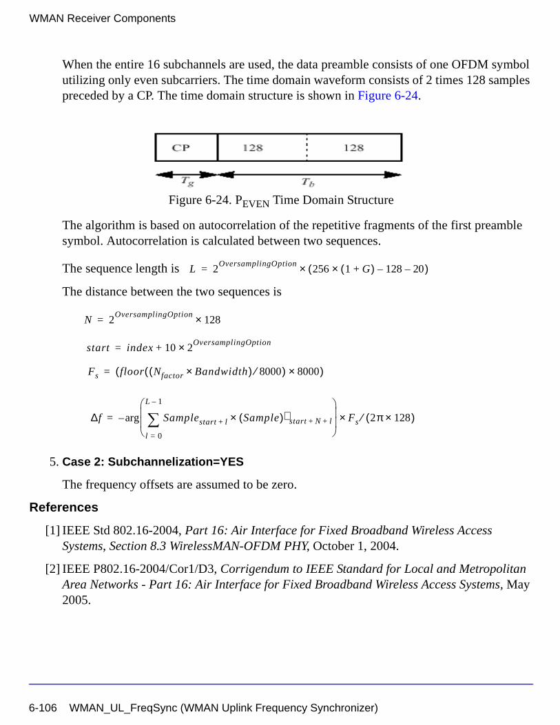
WMAN Receiver Components
When the entire 16 subchannels are used, the data preamble consists of one OFDM symbol utilizing only even subcarriers. The time domain waveform consists of 2 times 128 samples preceded by a CP. The time domain structure is shown in Figure 6-24.
Figure 6-24. PEVEN Time Domain Structure
The algorithm is based on autocorrelation of the repetitive fragments of the first preamble symbol. Autocorrelation is calculated between two sequences.
The sequence length is
The distance between the two sequences is
5. Case 2: Subchannelization=YES
The frequency offsets are assumed to be zero.
References
[1] IEEE Std 802.16-2004, Part 16: Air Interface for Fixed Broadband Wireless Access Systems, Section 8.3 WirelessMAN-OFDM PHY, October 1, 2004.
[2] IEEE P802.16-2004/Cor1/D3, Corrigendum to IEEE Standard for Local and Metropolitan Area Networks - Part 16: Air Interface for Fixed Broadband Wireless Access Systems, May 2005.
L 2OversamplingOption
256 1 G+( )× 128– 20–( )×=
N 2OversamplingOption
128×=
start index 10 2OversamplingOption×+=
Fs floor Nfactor Bandwidth×( ) 8000⁄( ) 8000×( )=
∆f Samplestart l+ Sample( )∗ start N l+ +×l 0=
L 1–
∑
Fs× 2π 128×( )⁄arg–=
6-106 WMAN_UL_FreqSync (WMAN Uplink Frequency Synchronizer)
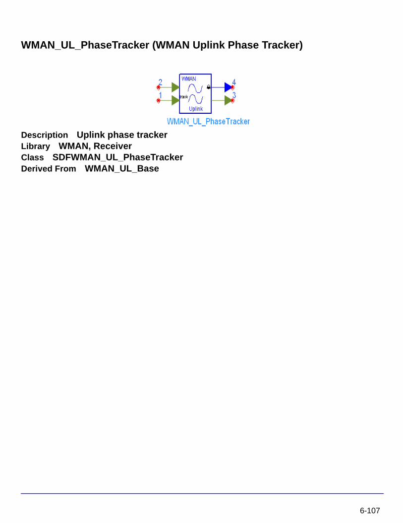
WMAN_UL_PhaseTracker (WMAN Uplink Phase Tracker)
Description Uplink phase trackerLibrary WMAN, ReceiverClass SDFWMAN_UL_PhaseTrackerDerived From WMAN_UL_Base
6-107
WMAN Receiver Components
Parameters
Pin Inputs
Pin Outputs
Notes/Equations
1. This model is used to track the phase in pilot subcarriers caused by the doppler shift in uplink demodulation systems, and update the estimated CIR (Channel impulse response) using the phase offset detected in the phase tracking algorithm.
2. Each firing,
• 200×NTotalDataSym tokens are consumed at pin Data.
where
NTotalDataSym is the number of total OFDM data symbols.
Name Description Default Type Range
NumberOfSS Number of subscribers 1 int [1, 16]
DataLength MAC PDU payload byte length of each subscriber
{100} int array [1, 16383]
Rate_ID Rate ID of each subscriber {1} int array [0, 6]
Subchannelization Subchannelization or not: NO, YES
NO enum
SubchannelIndex List of each subchannel index
{8} int array [1, 15] or [17, 31]
MidambleRepetition Midamble repetition of each subscriber
0 int array [0, 3]
PilotPN_Phase the Pilot PN phase 0 int [0, 2047]
Pin Name Description Signal Type
1 Data input of data symbol complex
2 CIR_Raw estimated channel impulse response input complex
Pin Name Description Signal Type
3 CIR_Track channel impulse response after phase track complex
4 Theta phase difference between current CIR and estimated CIR
real
6-108
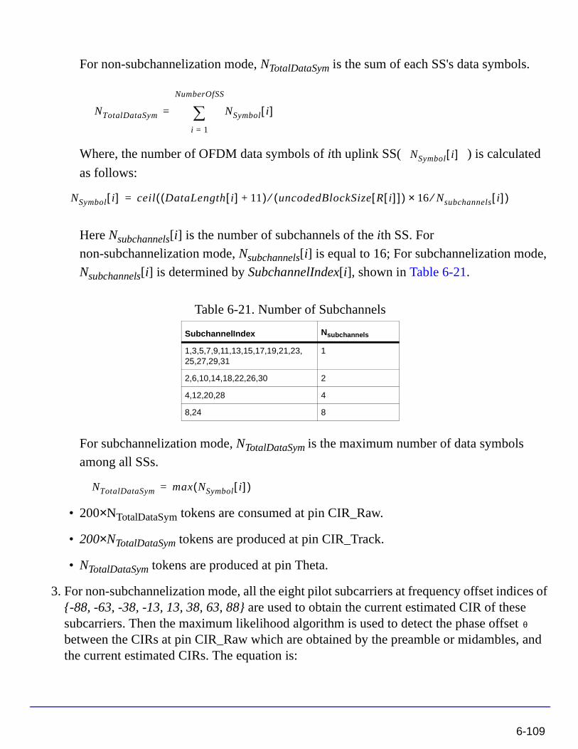
For non-subchannelization mode, NTotalDataSym is the sum of each SS's data symbols.
Where, the number of OFDM data symbols of ith uplink SS( ) is calculated
as follows:
Here Nsubchannels[i] is the number of subchannels of the ith SS. For
non-subchannelization mode, Nsubchannels[i] is equal to 16; For subchannelization mode,
Nsubchannels[i] is determined by SubchannelIndex[i], shown in Table 6-21.
For subchannelization mode, NTotalDataSym is the maximum number of data symbols
among all SSs.
• 200×NTotalDataSym tokens are consumed at pin CIR_Raw.
• 200×NTotalDataSym tokens are produced at pin CIR_Track.
• NTotalDataSym tokens are produced at pin Theta.
3. For non-subchannelization mode, all the eight pilot subcarriers at frequency offset indices of {-88, -63, -38, -13, 13, 38, 63, 88} are used to obtain the current estimated CIR of these subcarriers. Then the maximum likelihood algorithm is used to detect the phase offset between the CIRs at pin CIR_Raw which are obtained by the preamble or midambles, and the current estimated CIRs. The equation is:
Table 6-21. Number of Subchannels
SubchannelIndex Nsubchannels
1,3,5,7,9,11,13,15,17,19,21,23,25,27,29,31
1
2,6,10,14,18,22,26,30 2
4,12,20,28 4
8,24 8
NTotalDataSym NSymbol i[ ]i 1=
NumberOfSS
∑=
NSymbol i[ ]
NSymbol i[ ] ceil DataLength i[ ] 11+( ) uncodedBlockSize R i[ ][ ]( )⁄ 16 Nsubchannels⁄× i[ ]( )=
NTotalDataSym max NSymbol i[ ]( )=
θ
6-109
WMAN Receiver Components
where,
is the current estimated CIR.
is the previous estimated CIR obtained by the preamble or midambles
For subchannelization mode, only the pilot subcarriers assigned to the SS are used to detect the phase offset, assuming each SS has the different phase offset.
Finally the estimated CIRs from pin CIR_Raw are updated by the phase offset . For subchannelization mode, each SS's phase offset is only used to update CIR_Raw data belong to the same SS.
In non-subchannelization mode, set H0, H1, ... , H199 and , , ... , are the input
CIR_Raw and updated CIRs, respectively. Then
The updated CIRs are output at pin CIR_Track. The phase offset is output at pin Theta for non-subchannelization mode, and for subchannelization mode, the phase offset of the SS with FEC-encoded is output at pin Theta.
References
[1] IEEE Std 802.16-2004, Part 16: Air Interface for Fixed Broadband Wireless Access Systems, Section 8.3 WirelessMAN-OFDM PHY, October 1, 2004.
[2] IEEE P802.16-2004/Cor1/D3, Corrigendum to IEEE Standard for Local and Metropolitan Area Networks - Part 16: Air Interface for Fixed Broadband Wireless Access Systems, May 2005.
θ Hk conj H'k( )×k 1=
8
∑
arg=
Hk
H'k
θ
θ
H'0 H'1 H'199
H'i Hi ejθ×=
6-110
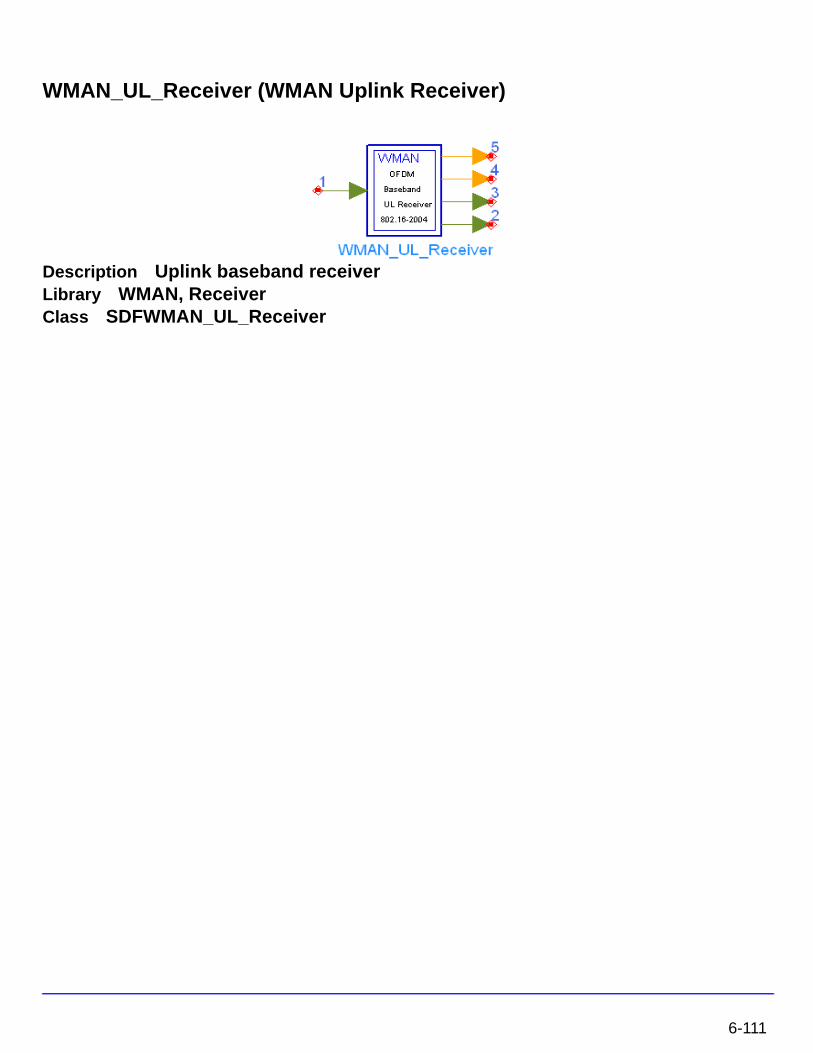
WMAN_UL_Receiver (WMAN Uplink Receiver)
Description Uplink baseband receiverLibrary WMAN, ReceiverClass SDFWMAN_UL_Receiver
6-111
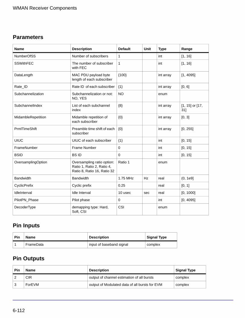
WMAN Receiver Components
Parameters
Pin Inputs
Pin Outputs
Name Description Default Unit Type Range
NumberOfSS Number of subscribers 1 int [1, 16]
SSWithFEC The number of subscriber with FEC
1 int [1, 16]
DataLength MAC PDU payload byte length of each subscriber
{100} int array [1, 4095]
Rate_ID Rate ID of each subscriber {1} int array [0, 6]
Subchannelization Subchannelization or not: NO, YES
NO enum
SubchannelIndex List of each subchannel index
{8} int array [1, 15] or [17, 31]
MidambleRepetition Midamble repetition of each subscriber
{0} int array [0, 3]
PrmlTimeShift Preamble time shift of each subscriber
{0} int array [0, 255]
UIUC UIUC of each subscriber {1} int [0, 15]
FrameNumber Frame Number 0 int [0, 15]
BSID BS ID 0 int [0, 15]
OversamplingOption Oversampling ratio option: Ratio 1, Ratio 2, Ratio 4, Ratio 8, Ratio 16, Ratio 32
Ratio 1 enum
Bandwidth Bandwidth 1.75 MHz Hz real (0, 1e9]
CyclicPrefix Cyclic prefix 0.25 real [0, 1]
IdleInterval Idle Interval 10 usec sec real [0, 1000]
PilotPN_Phase Pilot phase 0 int [0, 4095]
DecoderType demapping type: Hard, Soft, CSI
CSI enum
Pin Name Description Signal Type
1 FrameData input of baseband signal complex
Pin Name Description Signal Type
2 CIR output of channel estimation of all bursts complex
3 ForEVM output of Modulated data of all bursts for EVM complex
6-112
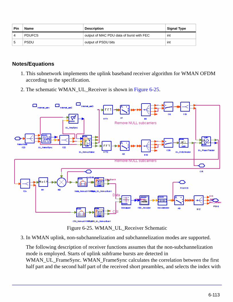
Notes/Equations
1. This subnetwork implements the uplink baseband receiver algorithm for WMAN OFDM according to the specification.
2. The schematic WMAN_UL_Receiver is shown in Figure 6-25.
Figure 6-25. WMAN_UL_Receiver Schematic
3. In WMAN uplink, non-subchannelization and subchannelization modes are supported.
The following description of receiver functions assumes that the non-subchannelization mode is employed. Starts of uplink subframe bursts are detected in WMAN_UL_FrameSync. WMAN_FrameSync calculates the correlation between the first half part and the second half part of the received short preambles, and selects the index with
4 PDUFCS output of MAC PDU data of burst with FEC int
5 PSDU output of PSDU bits int
Pin Name Description Signal Type
6-113
WMAN Receiver Components
the maximum correlation value as the start of each SS's burst. The start of each burst is send to WMAN_UL_DemuxFrame.
Frequency offsets are estimated in WMAN_UL_FreqSync. WMAN_UL_FreqSync calculates the frequency offset using the short preamble and sends the frequency offset to WMAN_UL_DemuxFrame.
According to the starts of uplink subframe bursts, the uplink subframe is de-multiplex into several parts in WMAN_UL_DemuxFrame, including contention slots for Initial Ranging and BW Requests, the short preamble, midambles and data symbols. The phase effect caused by the frequency offset is compensated, and the idle interval and the cyclic prefix of each OFDM symbol are also removed in WMAN_UL_DemuxFrame.
The data symbols, short preamble and midambles are passed into frequency domain through FFT transformation. The short preamble and midambles used for channel estimation, where channel estimation is done in WMAN_UL_ChEstimation.
WMAN_UL_ChEstimation uses the preambles and midambles to get the channel impulse response (CIR) coefficients. First the CIRs in the even subcarriers are calculated by a simple divider, then the CIRs in the odd subcarriers are interpolated by a FIR filter. Finally WMAN_UL_ChEstimation duplicates the estimated CIRs the number of data symbols. The channel estimation result is output at pin CIR.
WMAN_UL_PhaseTracker is used to track the phase caused by doppler frequency shift by comparing the previous CIRs and the CIRs in pilot subcarriers of the current data symbols. Then the estimated CIR is updated according to the phase offset detected.
After the estimated CIRs going through WMAN_UL_PhaseTracker, they are used for channel equalization which is implemented by a simple divider. The equalized data are output at pin ForEVM for EVM measurements.
Then the pilot subcarriers are removed from the equalized signals in WMAN_DemuxOFDMSym, and the burst with FEC-encoded is separated from the bursts chain in WMAN_DemuxBurst which is send to WMAN_Demapper. In WMAN_Demapper, Three demapper types (CSI, Soft and Hard) are supported.
After FEC decoding, de-interleaving, de-scrambling, the MAC PDU data are obtained, which are divided into MAC header, MAC PDU payloads and CRC. The MAC PDU and its payloads are output at pin PDUFCS and PSDU respectively.
In subchannelization mode, because all SSs share one burst using different subchannels, only one start of uplink subframe burst will be detected in WMAN_UL_FrameSync. And WMAN_UL_FreqSync will do nothing, resulting in no frequency offset compensation is needed in WMAN_DemuxFrame. In WMAN_UL_ChEstimation, no interpolation is
6-114
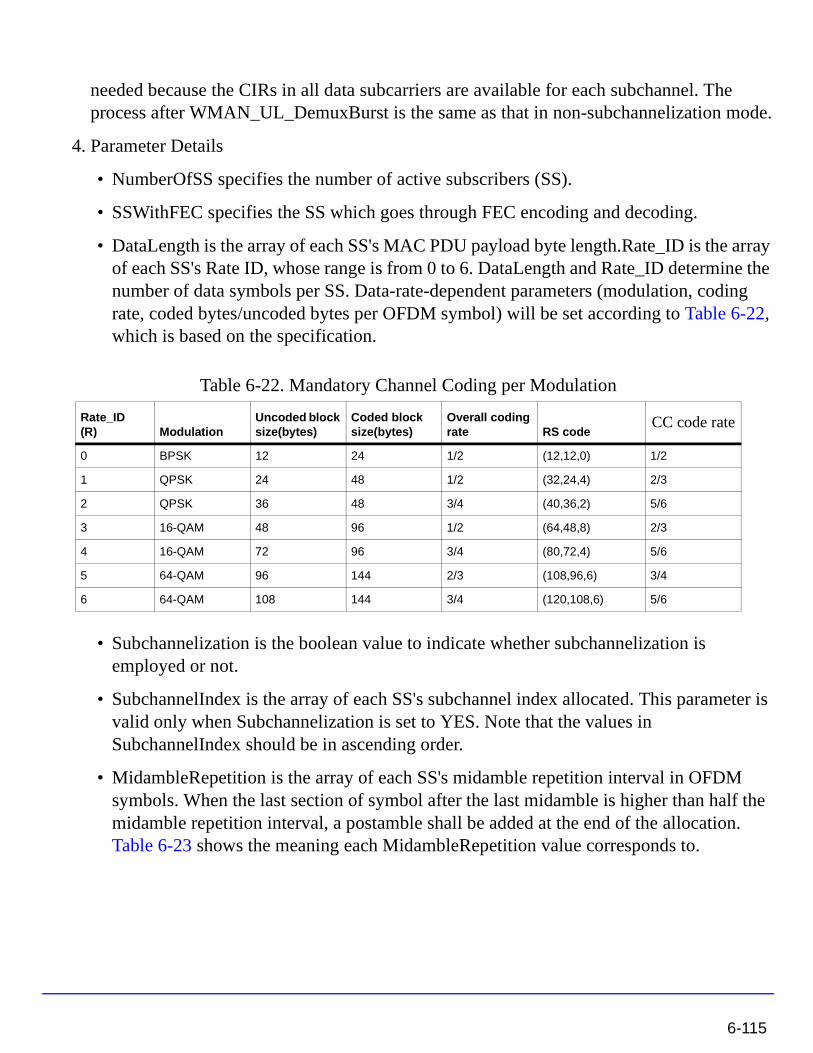
needed because the CIRs in all data subcarriers are available for each subchannel. The process after WMAN_UL_DemuxBurst is the same as that in non-subchannelization mode.
4. Parameter Details
• NumberOfSS specifies the number of active subscribers (SS).
• SSWithFEC specifies the SS which goes through FEC encoding and decoding.
• DataLength is the array of each SS's MAC PDU payload byte length.Rate_ID is the array of each SS's Rate ID, whose range is from 0 to 6. DataLength and Rate_ID determine the number of data symbols per SS. Data-rate-dependent parameters (modulation, coding rate, coded bytes/uncoded bytes per OFDM symbol) will be set according to Table 6-22, which is based on the specification.
• Subchannelization is the boolean value to indicate whether subchannelization is employed or not.
• SubchannelIndex is the array of each SS's subchannel index allocated. This parameter is valid only when Subchannelization is set to YES. Note that the values in SubchannelIndex should be in ascending order.
• MidambleRepetition is the array of each SS's midamble repetition interval in OFDM symbols. When the last section of symbol after the last midamble is higher than half the midamble repetition interval, a postamble shall be added at the end of the allocation. Table 6-23 shows the meaning each MidambleRepetition value corresponds to.
Table 6-22. Mandatory Channel Coding per Modulation
Rate_ID(R) Modulation
Uncoded block size(bytes)
Coded block size(bytes)
Overall coding rate RS code
CC code rate
0 BPSK 12 24 1/2 (12,12,0) 1/2
1 QPSK 24 48 1/2 (32,24,4) 2/3
2 QPSK 36 48 3/4 (40,36,2) 5/6
3 16-QAM 48 96 1/2 (64,48,8) 2/3
4 16-QAM 72 96 3/4 (80,72,4) 5/6
5 64-QAM 96 144 2/3 (108,96,6) 3/4
6 64-QAM 108 144 3/4 (120,108,6) 5/6
6-115
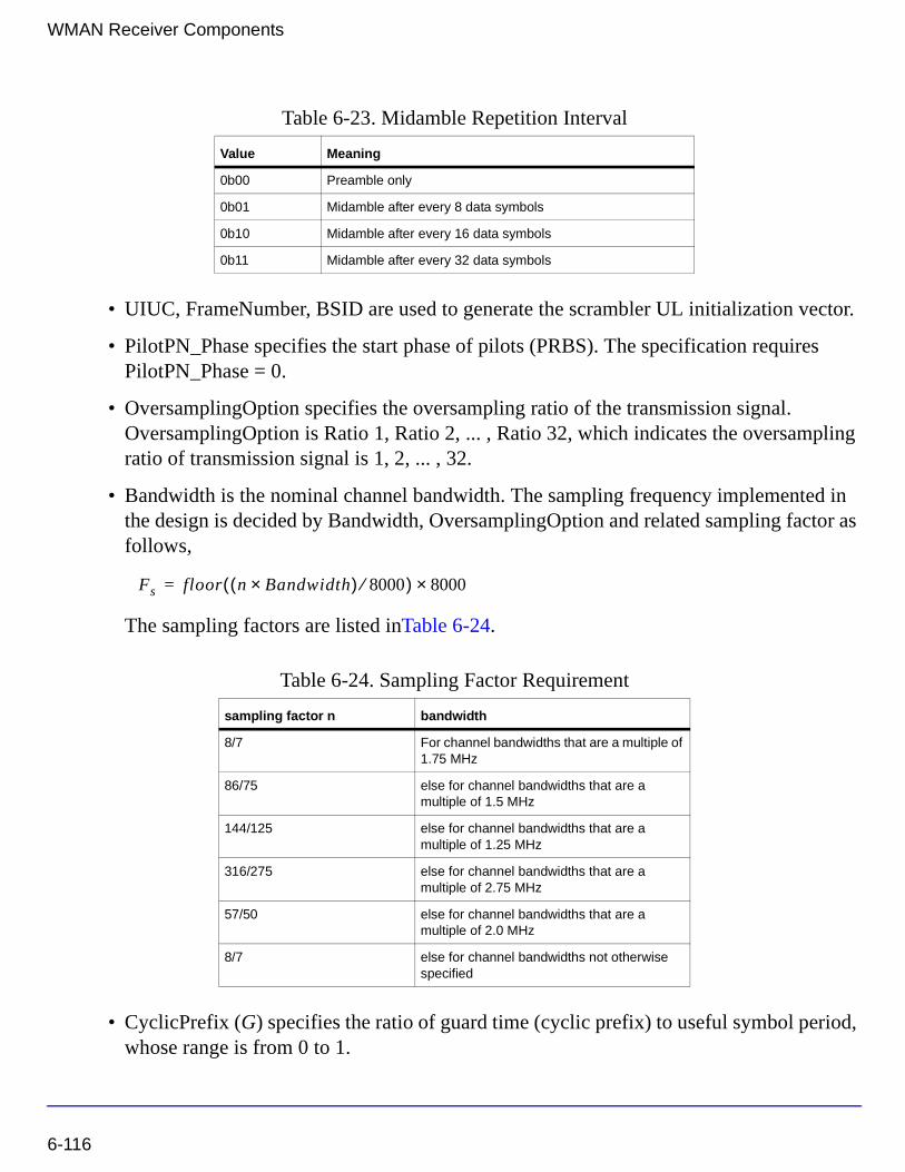
WMAN Receiver Components
• UIUC, FrameNumber, BSID are used to generate the scrambler UL initialization vector.
• PilotPN_Phase specifies the start phase of pilots (PRBS). The specification requires PilotPN_Phase = 0.
• OversamplingOption specifies the oversampling ratio of the transmission signal. OversamplingOption is Ratio 1, Ratio 2, ... , Ratio 32, which indicates the oversampling ratio of transmission signal is 1, 2, ... , 32.
• Bandwidth is the nominal channel bandwidth. The sampling frequency implemented in the design is decided by Bandwidth, OversamplingOption and related sampling factor as follows,
The sampling factors are listed inTable 6-24.
• CyclicPrefix (G) specifies the ratio of guard time (cyclic prefix) to useful symbol period, whose range is from 0 to 1.
Table 6-23. Midamble Repetition Interval
Value Meaning
0b00 Preamble only
0b01 Midamble after every 8 data symbols
0b10 Midamble after every 16 data symbols
0b11 Midamble after every 32 data symbols
Table 6-24. Sampling Factor Requirement
sampling factor n bandwidth
8/7 For channel bandwidths that are a multiple of 1.75 MHz
86/75 else for channel bandwidths that are a multiple of 1.5 MHz
144/125 else for channel bandwidths that are a multiple of 1.25 MHz
316/275 else for channel bandwidths that are a multiple of 2.75 MHz
57/50 else for channel bandwidths that are a multiple of 2.0 MHz
8/7 else for channel bandwidths not otherwise specified
Fs floor n Bandwidth×( ) 8000⁄( ) 8000×=
6-116
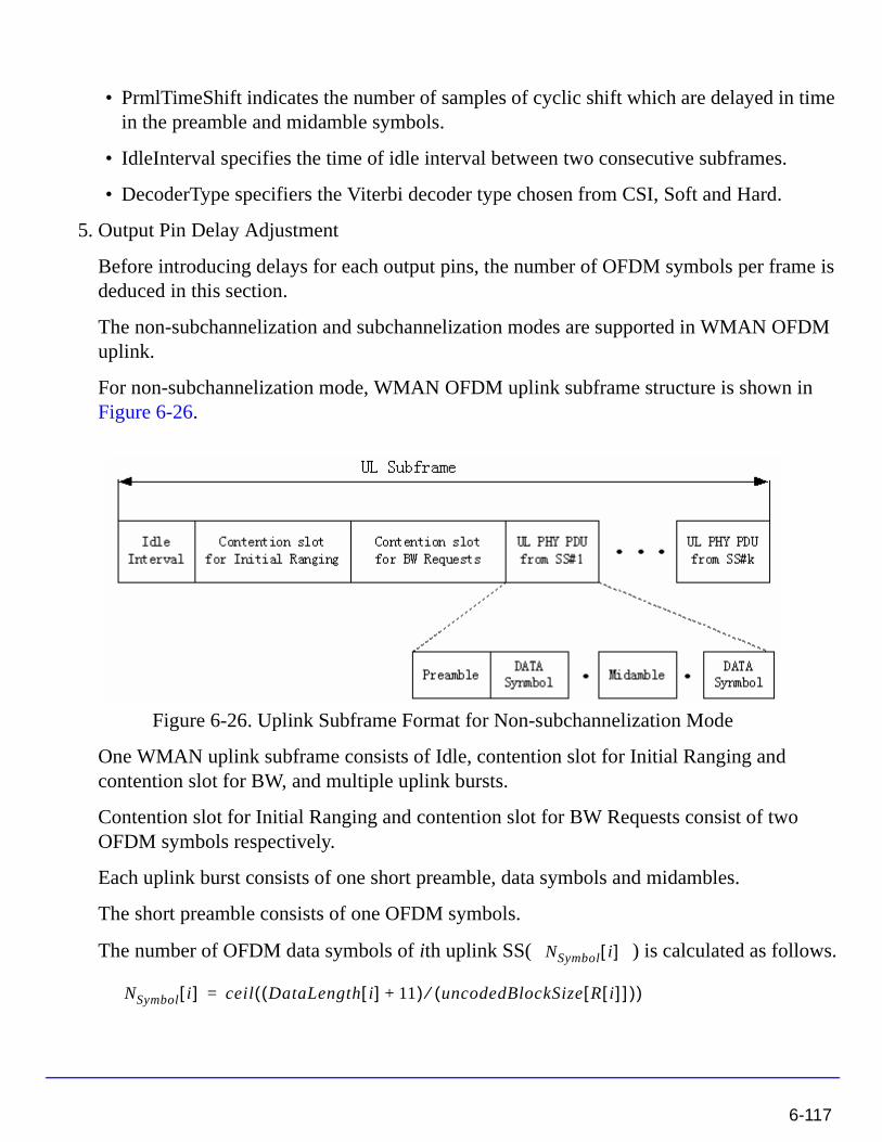
• PrmlTimeShift indicates the number of samples of cyclic shift which are delayed in time in the preamble and midamble symbols.
• IdleInterval specifies the time of idle interval between two consecutive subframes.
• DecoderType specifiers the Viterbi decoder type chosen from CSI, Soft and Hard.
5. Output Pin Delay Adjustment
Before introducing delays for each output pins, the number of OFDM symbols per frame is deduced in this section.
The non-subchannelization and subchannelization modes are supported in WMAN OFDM uplink.
For non-subchannelization mode, WMAN OFDM uplink subframe structure is shown in Figure 6-26.
Figure 6-26. Uplink Subframe Format for Non-subchannelization Mode
One WMAN uplink subframe consists of Idle, contention slot for Initial Ranging and contention slot for BW, and multiple uplink bursts.
Contention slot for Initial Ranging and contention slot for BW Requests consist of two OFDM symbols respectively.
Each uplink burst consists of one short preamble, data symbols and midambles.
The short preamble consists of one OFDM symbols.
The number of OFDM data symbols of ith uplink SS( ) is calculated as follows.NSymbol i[ ]
NSymbol i[ ] ceil DataLength i[ ] 11+( ) uncodedBlockSize R i[ ][ ]( )⁄( )=
6-117
WMAN Receiver Components
MidambleRepetition indicates each SS's midamble repetition interval in OFDM symbols. Let represent the number of midamble symbols in ith uplink burst,
if is not zero
else
So the total number of OFDM symbols for the uplink frame is calculated as
follows:
The number of samples per one OFDM symbol ( ) is calculated as:
where, G is the CyclicPrefix.
The samples of IdleInterval( ) is calculated as follows:
So, the total samples of one uplink subframe is
For subchannelization mode, WMAN OFDM Uplink subframe structure is shown in Figure 6-27.
Midamble i[ ]
MidambleRepetition i[ ]
Midamble i[ ] round NSymbol i[ ]( ) 2MidambleRepetition i[ ] 1+⁄( )=
Midamble i[ ] 0=
NtotalSymbol
NtotalSymbol 2 2 NSymbol i[ ] 1 Midamble i[ ]+ +( )i 1=
NumberOfSS
∑+ +=
SamplesOFDM
SamplesOFDM 2OversamplingOption
256× 1 G+( )×=
Samplesidle
Samplesidle IdleInterval Fs×=
SamplesFrame
SamplesFrame Samplesidle NtotalSymbol SamplesOFDM×+=
6-118
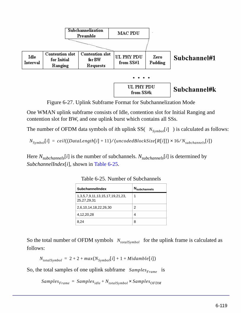
Figure 6-27. Uplink Subframe Format for Subchannelization Mode
One WMAN uplink subframe consists of Idle, contention slot for Initial Ranging and contention slot for BW, and one uplink burst which contains all SSs.
The number of OFDM data symbols of ith uplink SS( ) is calculated as follows:
Here Nsubchannels[i] is the number of subchannels. Nsubchannels[i] is determined by
SubchannelIndex[i], shown in Table 6-25.
So the total number of OFDM symbols for the uplink frame is calculated as
follows:
So, the total samples of one uplink subframe is
Table 6-25. Number of Subchannels
SubchannelIndex Nsubchannels
1,3,5,7,9,11,13,15,17,19,21,23,25,27,29,31
1
2,6,10,14,18,22,26,30 2
4,12,20,28 4
8,24 8
NSymbol i[ ]
NSymbol i[ ] ceil DataLength i[ ] 11+( ) uncodedBlockSize R i[ ][ ]( )⁄ 16 Nsubchannels⁄× i[ ]( )=
NtotalSymbol
NtotalSymbol 2 2 max NSymbol i[ ] 1 Midamble i[ ]+ +( )+ +=
SamplesFrame
SamplesFrame Samplesidle NtotalSymbol SamplesOFDM×+=
6-119

WMAN Receiver Components
In the receiver, one frame delay occurs.
delay is introduced at pin ForEVM and CIR for
non-subchannelization mode and delay for subchannelization mode.
bits delay is introduced at pin PDUFCS, where 80 bits are the MAC Header and CRC attached.
bits delay is introduced at pin PSDU.
References
[1] IEEE Std 802.16-2004, Part 16: Air Interface for Fixed Broadband Wireless Access Systems, Section 8.3 WirelessMAN-OFDM PHY, October 1, 2004.
[2] IEEE P802.16-2004/Cor1/D3, Corrigendum to IEEE Standard for Local and Metropolitan Area Networks - Part 16: Air Interface for Fixed Broadband Wireless Access Systems, May 2005.
200 NSymbol i[ ]i 1=
NumberOfSS
∑
×
200 max NSymbol i[ ]( )×
8 DataLength BurstWithFEC[ ]× 80+
8 DataLength BurstWithFEC[ ]×
6-120
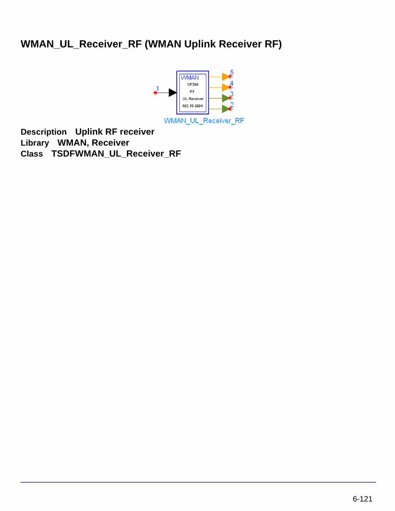
WMAN_UL_Receiver_RF (WMAN Uplink Receiver RF)
Description Uplink RF receiverLibrary WMAN, ReceiverClass TSDFWMAN_UL_Receiver_RF
6-121
WMAN Receiver Components
Parameters
Name Description Default Unit Type Range
RIn input resistance 50 Ohm Ohm int (0, ∞)
RTemp TEMPERATURE - 273.15 Celsius real [- 273.15, ∞]
FCarrier Carrier frequency 3407 MHz Hz real (0, ∞)
Sensitivity voltage output sensitivity, Vout/Vin
1 real (-∞, ∞)
Phase Reference phase in degrees
0.0 deg real (-∞, ∞)
GainImbalance Gain imbalance in dB Q channel relative to I channel
0.0 real (-∞, ∞)
PhaseImbalance Phase imbalance in dB Q channel relative to I channel
0.0 real (-∞, ∞)
NumberOfSS Number of subscribers 1 int [1, 16]
SSWithFEC The number of subscriber with FEC
1 int [1, 16]
DataLength MAC PDU payload byte length of each subscriber
{100} int array [1, 4095]
Rate_ID Rate ID of each subscriber {1} int array [0, 6]
Subchannelization Subchannelization or not: NO, YES
NO enum
SubchannelIndex List of each subchannel index
{8} int array [1, 15] or [17, 31]
MidambleRepetition Midamble repetition of each subscriber
{0} int array [0, 3]
PrmlTimeShift Preamble time shift of each subscriber
{0} int array [0, 255]
UIUC UIUC of each subscriber {1} int [0, 15]
FrameNumber Frame Number 0 int [0, 15]
BSID BS ID 0 int [0, 15]
OversamplingOption Oversampling ratio option: Ratio 1, Ratio 2, Ratio 4, Ratio 8, Ratio 16, Ratio 32
Ratio 1 enum
Bandwidth Bandwidth 1.75 MHz Hz real (0, 1e9]
CyclicPrefix Cyclic prefix 0.25 real [0, 1]
IdleInterval Idle Interval 10 usec sec real [0, 1000]
6-122
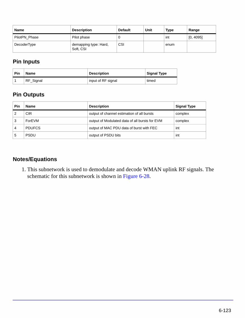
Pin Inputs
Pin Outputs
Notes/Equations
1. This subnetwork is used to demodulate and decode WMAN uplink RF signals. The schematic for this subnetwork is shown in Figure 6-28.
PilotPN_Phase Pilot phase 0 int [0, 4095]
DecoderType demapping type: Hard, Soft, CSI
CSI enum
Pin Name Description Signal Type
1 RF_Signal input of RF signal timed
Pin Name Description Signal Type
2 CIR output of channel estimation of all bursts complex
3 ForEVM output of Modulated data of all bursts for EVM complex
4 PDUFCS output of MAC PDU data of burst with FEC int
5 PSDU output of PSDU bits int
Name Description Default Unit Type Range
6-123
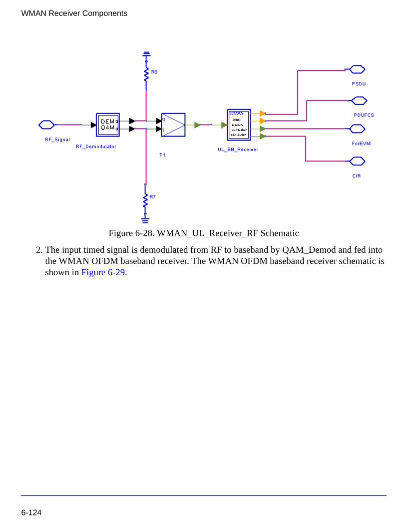
WMAN Receiver Components
Figure 6-28. WMAN_UL_Receiver_RF Schematic
2. The input timed signal is demodulated from RF to baseband by QAM_Demod and fed into the WMAN OFDM baseband receiver. The WMAN OFDM baseband receiver schematic is shown in Figure 6-29.
6-124
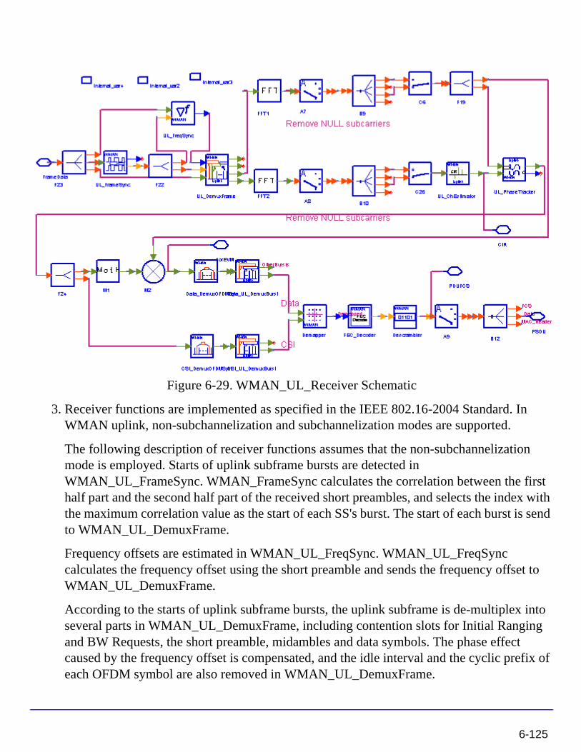
Figure 6-29. WMAN_UL_Receiver Schematic
3. Receiver functions are implemented as specified in the IEEE 802.16-2004 Standard. In WMAN uplink, non-subchannelization and subchannelization modes are supported.
The following description of receiver functions assumes that the non-subchannelization mode is employed. Starts of uplink subframe bursts are detected in WMAN_UL_FrameSync. WMAN_FrameSync calculates the correlation between the first half part and the second half part of the received short preambles, and selects the index with the maximum correlation value as the start of each SS's burst. The start of each burst is send to WMAN_UL_DemuxFrame.
Frequency offsets are estimated in WMAN_UL_FreqSync. WMAN_UL_FreqSync calculates the frequency offset using the short preamble and sends the frequency offset to WMAN_UL_DemuxFrame.
According to the starts of uplink subframe bursts, the uplink subframe is de-multiplex into several parts in WMAN_UL_DemuxFrame, including contention slots for Initial Ranging and BW Requests, the short preamble, midambles and data symbols. The phase effect caused by the frequency offset is compensated, and the idle interval and the cyclic prefix of each OFDM symbol are also removed in WMAN_UL_DemuxFrame.
6-125
WMAN Receiver Components
The data symbols, short preamble and midambles are passed into frequency domain through FFT transformation. The short preamble and midambles used for channel estimation, where channel estimation is done in WMAN_UL_ChEstimation.
WMAN_UL_ChEstimation uses the preambles and midambles to get the channel impulse response (CIR) coefficients. First the CIRs in the even subcarriers are calculated by a simple divider, then the CIRs in the odd subcarriers are interpolated by a FIR filter. Finally WMAN_UL_ChEstimation duplicates the estimated CIRs the number of data symbols. The channel estimation result is output at pin CIR.
WMAN_UL_PhaseTracker is used to track the phase caused by doppler frequency shift by comparing previous CIRs and the CIRs in pilot subcarriers of the current data symbols. Then the estimated CIR is updated according to the phase offset detected.
After the estimated CIRs going through WMAN_UL_PhaseTracker, they are used for channel equalization which is implemented by a simple divider. The equalized data are output at pin ForEVM for EVM measurements.
Then the pilot subcarriers are removed from the equalized signals in WMAN_DemuxOFDMSym, and the burst with FEC-encoded is separated from the bursts chain in WMAN_DemuxBurst which is send to WMAN_Demapper. In WMAN_Demapper, Three demapper types (CSI, Soft and Hard) are supported.
After FEC decoding, de-interleaving, de-scrambling, the MAC PDU data are obtained, which are divided into MAC header, MAC PDU payloads and CRC. The MAC PDU and its payloads are output at pin PDUFCS and PSDU respectively.
In subchannelization mode, because all SSs share one burst using different subchannels, only one start of uplink subframe burst will be detected in WMAN_UL_FrameSync. And WMAN_UL_FreqSync will do nothing, resulting in no frequency offset compensation is needed in WMAN_DemuxFrame. In WMAN_UL_ChEstimation, no interpolation is needed because the CIRs in all data subcarriers are available for each subchannel. The process after WMAN_UL_DemuxBurst is the same as that in non-subchannelization mode.
4. Parameter Details
• RIn is the RF input source resistance.
• RTemp is the RF output source resistance temperature in Celsius and sets the noise density in the RF output signal to (k(RTemp+273.15)) Watts/Hz, where k is Boltzmann's constant.
• FCarrier parameter is the RF signal frequency.
6-126
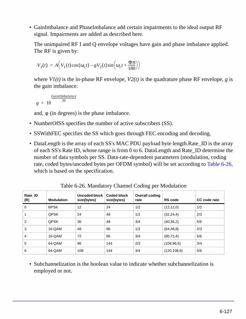
• GainImbalance and PhaseImbalance add certain impairments to the ideal output RF signal. Impairments are added as described here.
The unimpaired RF I and Q envelope voltages have gain and phase imbalance applied. The RF is given by:
where V1(t) is the in-phase RF envelope, V2(t) is the quadrature phase RF envelope, g is the gain imbalance:
and, (in degrees) is the phase imbalance.
• NumberOfSS specifies the number of active subscribers (SS).
• SSWithFEC specifies the SS which goes through FEC encoding and decoding.
• DataLength is the array of each SS's MAC PDU payload byte length.Rate_ID is the array of each SS's Rate ID, whose range is from 0 to 6. DataLength and Rate_ID determine the number of data symbols per SS. Data-rate-dependent parameters (modulation, coding rate, coded bytes/uncoded bytes per OFDM symbol) will be set according to Table 6-26, which is based on the specification.
• Subchannelization is the boolean value to indicate whether subchannelization is employed or not.
Table 6-26. Mandatory Channel Coding per Modulation
Rate_ID(R) Modulation
Uncoded block size(bytes)
Coded block size(bytes)
Overall coding rate RS code CC code rate
0 BPSK 12 24 1/2 (12,12,0) 1/2
1 QPSK 24 48 1/2 (32,24,4) 2/3
2 QPSK 36 48 3/4 (40,36,2) 5/6
3 16-QAM 48 96 1/2 (64,48,8) 2/3
4 16-QAM 72 96 3/4 (80,72,4) 5/6
5 64-QAM 96 144 2/3 (108,96,6) 3/4
6 64-QAM 108 144 3/4 (120,108,6) 5/6
V3 t( ) A V1 t( ) ωct( )cos gV2 t( ) ωctΦπ180---------+
sin– =
g 10
GainImbalance20
-----------------------------------------
=
φ
6-127
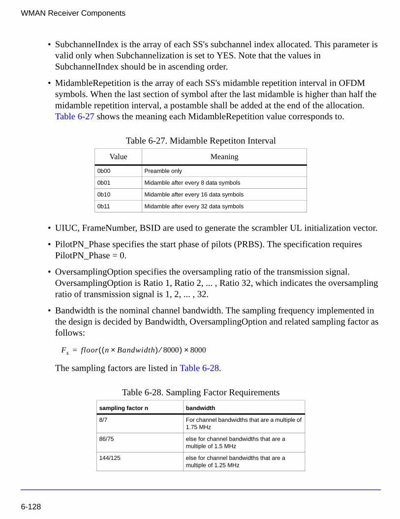
WMAN Receiver Components
• SubchannelIndex is the array of each SS's subchannel index allocated. This parameter is valid only when Subchannelization is set to YES. Note that the values in SubchannelIndex should be in ascending order.
• MidambleRepetition is the array of each SS's midamble repetition interval in OFDM symbols. When the last section of symbol after the last midamble is higher than half the midamble repetition interval, a postamble shall be added at the end of the allocation. Table 6-27 shows the meaning each MidambleRepetition value corresponds to.
• UIUC, FrameNumber, BSID are used to generate the scrambler UL initialization vector.
• PilotPN_Phase specifies the start phase of pilots (PRBS). The specification requires PilotPN_Phase = 0.
• OversamplingOption specifies the oversampling ratio of the transmission signal. OversamplingOption is Ratio 1, Ratio 2, ... , Ratio 32, which indicates the oversampling ratio of transmission signal is 1, 2, ... , 32.
• Bandwidth is the nominal channel bandwidth. The sampling frequency implemented in the design is decided by Bandwidth, OversamplingOption and related sampling factor as follows:
The sampling factors are listed in Table 6-28.
Table 6-27. Midamble Repetiton Interval
Value Meaning
0b00 Preamble only
0b01 Midamble after every 8 data symbols
0b10 Midamble after every 16 data symbols
0b11 Midamble after every 32 data symbols
Table 6-28. Sampling Factor Requirements
sampling factor n bandwidth
8/7 For channel bandwidths that are a multiple of 1.75 MHz
86/75 else for channel bandwidths that are a multiple of 1.5 MHz
144/125 else for channel bandwidths that are a multiple of 1.25 MHz
Fs floor n Bandwidth×( ) 8000⁄( ) 8000×=
6-128
• CyclicPrefix (G) specifies the ratio of guard time (cyclic prefix) to useful symbol period, whose range is from 0 to 1.
• PrmlTimeShift indicates the number of samples of cyclic shift which are delayed in time in the preamble and midamble symbols.
• IdleInterval specifies the time of idle interval between two consecutive subframes.
• DecoderType specifiers the Viterbi decoder type chosen from CSI, Soft and Hard.
5. Output Pin Delay Adjustment
Before introducing delays for each output pins, the number of OFDM symbols per frame is deduced in this section.
The non-subchannelization and subchannelization modes are supported in WMAN OFDM uplink.
For non-subchannelization mode, WMAN OFDM uplink subframe structure is shown in Figure 6-30.
Figure 6-30. Uplink Subframe Format for Non-subchannelization Mode
One WMAN uplink subframe consists of Idle, contention slot for Initial Ranging and contention slot for BW, and multiple uplink bursts.
316/275 else for channel bandwidths that are a multiple of 2.75 MHz
57/50 else for channel bandwidths that are a multiple of 2.0 MHz
8/7 else for channel bandwidths not otherwise specified
Table 6-28. Sampling Factor Requirements
sampling factor n bandwidth
6-129
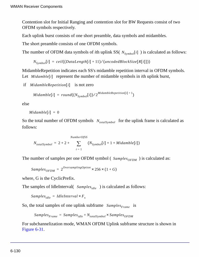
WMAN Receiver Components
Contention slot for Initial Ranging and contention slot for BW Requests consist of two OFDM symbols respectively.
Each uplink burst consists of one short preamble, data symbols and midambles.
The short preamble consists of one OFDM symbols.
The number of OFDM data symbols of ith uplink SS( ) is calculated as follows:
MidambleRepetition indicates each SS's midamble repetition interval in OFDM symbols. Let represent the number of midamble symbols in ith uplink burst,
if is not zero
else
So the total number of OFDM symbols for the uplink frame is calculated as
follows:
The number of samples per one OFDM symbol ( ) is calculated as:
where, G is the CyclicPrefix.
The samples of IdleInterval( ) is calculated as follows:
So, the total samples of one uplink subframe is
For subchannelization mode, WMAN OFDM Uplink subframe structure is shown in Figure 6-31.
NSymbol i[ ]
NSymbol i[ ] ceil DataLength i[ ] 11+( ) uncodedBlockSize R i[ ][ ]( )⁄( )=
Midamble i[ ]
MidambleRepetition i[ ]
Midamble i[ ] round NSymbol i[ ]( ) 2MidambleRepetition i[ ] 1+⁄( )=
Midamble i[ ] 0=
NtotalSymbol
NtotalSymbol 2 2 NSymbol i[ ] 1 Midamble i[ ]+ +( )i 1=
NumberOfSS
∑+ +=
SamplesOFDM
SamplesOFDM 2OversamplingOption
256× 1 G+( )×=
Samplesidle
Samplesidle IdleInterval Fs×=
SamplesFrame
SamplesFrame Samplesidle NtotalSymbol SamplesOFDM×+=
6-130
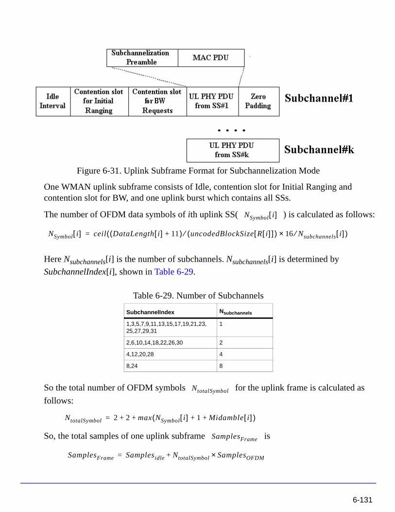
Figure 6-31. Uplink Subframe Format for Subchannelization Mode
One WMAN uplink subframe consists of Idle, contention slot for Initial Ranging and contention slot for BW, and one uplink burst which contains all SSs.
The number of OFDM data symbols of ith uplink SS( ) is calculated as follows:
Here Nsubchannels[i] is the number of subchannels. Nsubchannels[i] is determined by
SubchannelIndex[i], shown in Table 6-29.
So the total number of OFDM symbols for the uplink frame is calculated as
follows:
So, the total samples of one uplink subframe is
Table 6-29. Number of Subchannels
SubchannelIndex Nsubchannels
1,3,5,7,9,11,13,15,17,19,21,23,25,27,29,31
1
2,6,10,14,18,22,26,30 2
4,12,20,28 4
8,24 8
NSymbol i[ ]
NSymbol i[ ] ceil DataLength i[ ] 11+( ) uncodedBlockSize R i[ ][ ]( )⁄ 16 Nsubchannels⁄× i[ ]( )=
NtotalSymbol
NtotalSymbol 2 2 max NSymbol i[ ] 1 Midamble i[ ]+ +( )+ +=
SamplesFrame
SamplesFrame Samplesidle NtotalSymbol SamplesOFDM×+=
6-131
WMAN Receiver Components
In the receiver, one frame delay occurs.
delay is introduced at pin ForEVM and CIR for
non-subchannelization mode and delay for subchannelization mode.
bits delay is introduced at pin PDUFCS, where 80 bits are the MAC Header and CRC attached.
bits delay is introduced at pin PSDU.
References
[1] IEEE Std 802.16-2004, Part 16: Air Interface for Fixed Broadband Wireless Access Systems, Section 8.3 WirelessMAN-OFDM PHY, October 1, 2004.
[2] IEEE P802.16-2004/Cor1/D3, Corrigendum to IEEE Standard for Local and Metropolitan Area Networks - Part 16: Air Interface for Fixed Broadband Wireless Access Systems, May 2005.
200 NSymbol i[ ]i 1=
NumberOfSS
∑
×
200 max NSymbol i[ ]( )×
8 DataLength BurstWithFEC[ ]× 80+
8 DataLength BurstWithFEC[ ]×
6-132
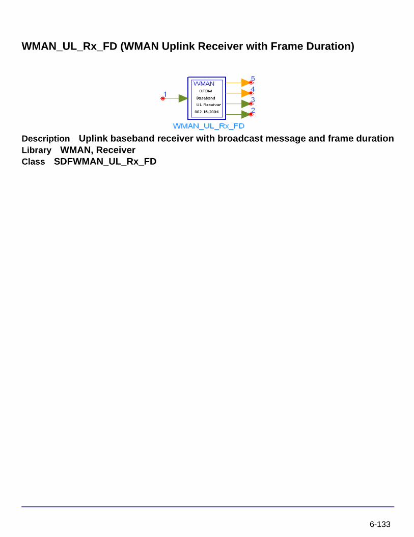
WMAN_UL_Rx_FD (WMAN Uplink Receiver with Frame Duration)
Description Uplink baseband receiver with broadcast message and frame durationLibrary WMAN, ReceiverClass SDFWMAN_UL_Rx_FD
6-133
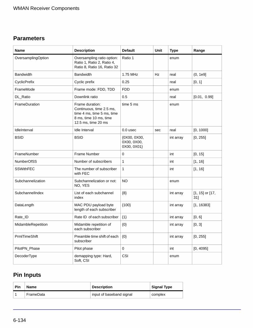
WMAN Receiver Components
Parameters
Pin Inputs
Name Description Default Unit Type Range
OversamplingOption Oversampling ratio option: Ratio 1, Ratio 2, Ratio 4, Ratio 8, Ratio 16, Ratio 32
Ratio 1 enum
Bandwidth Bandwidth 1.75 MHz Hz real (0, 1e9]
CyclicPrefix Cyclic prefix 0.25 real [0, 1]
FrameMode Frame mode: FDD, TDD FDD enum
DL_Ratio Downlink ratio 0.5 real [0.01, 0.99]
FrameDuration Frame duration: Continuous, time 2.5 ms, time 4 ms, time 5 ms, time 8 ms, time 10 ms, time 12.5 ms, time 20 ms
time 5 ms enum
IdleInterval Idle Interval 0.0 usec sec real [0, 1000]
BSID BSID {0X00, 0X00, 0X00, 0X00, 0X00, 0X01}
int array [0, 255]
FrameNumber Frame Number 0 int [0, 15]
NumberOfSS Number of subscribers 1 int [1, 16]
SSWithFEC The number of subscriber with FEC
1 int [1, 16]
Subchannelization Subchannelization or not: NO, YES
NO enum
SubchannelIndex List of each subchannel index
{8} int array [1, 15] or [17, 31]
DataLength MAC PDU payload byte length of each subscriber
{100} int array [1, 16383]
Rate_ID Rate ID of each subscriber {1} int array [0, 6]
MidambleRepetition Midamble repetition of each subscriber
{0} int array [0, 3]
PrmlTimeShift Preamble time shift of each subscriber
{0} int array [0, 255]
PilotPN_Phase Pilot phase 0 int [0, 4095]
DecoderType demapping type: Hard, Soft, CSI
CSI enum
Pin Name Description Signal Type
1 FrameData input of baseband signal complex
6-134
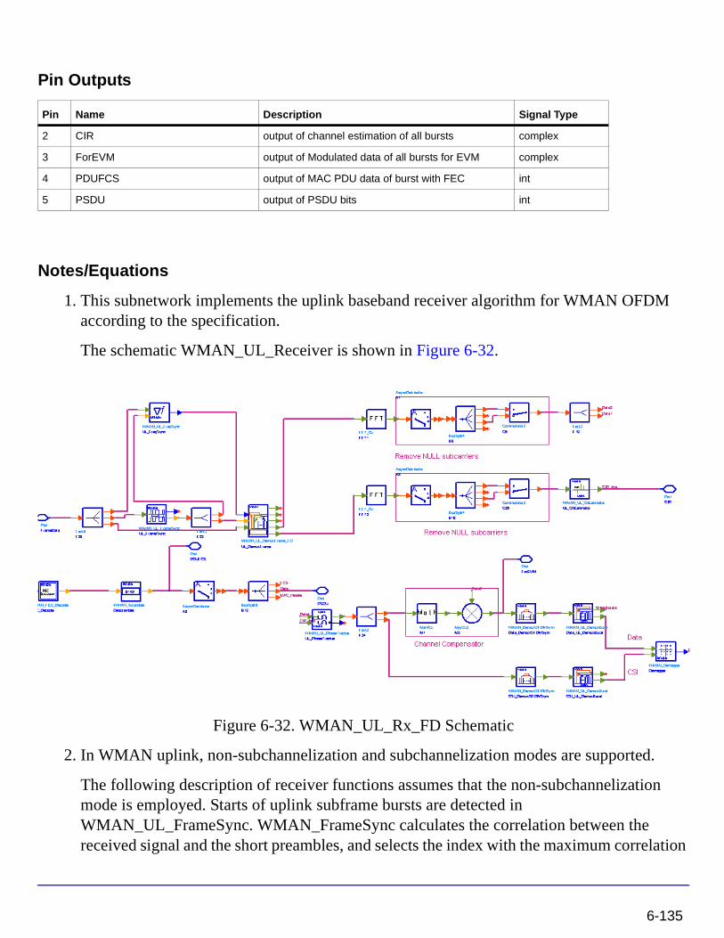
Pin Outputs
Notes/Equations
1. This subnetwork implements the uplink baseband receiver algorithm for WMAN OFDM according to the specification.
The schematic WMAN_UL_Receiver is shown in Figure 6-32.
Figure 6-32. WMAN_UL_Rx_FD Schematic
2. In WMAN uplink, non-subchannelization and subchannelization modes are supported.
The following description of receiver functions assumes that the non-subchannelization mode is employed. Starts of uplink subframe bursts are detected in WMAN_UL_FrameSync. WMAN_FrameSync calculates the correlation between the received signal and the short preambles, and selects the index with the maximum correlation
Pin Name Description Signal Type
2 CIR output of channel estimation of all bursts complex
3 ForEVM output of Modulated data of all bursts for EVM complex
4 PDUFCS output of MAC PDU data of burst with FEC int
5 PSDU output of PSDU bits int
6-135
WMAN Receiver Components
value as the start of each SS's burst. The start of each burst is send to WMAN_UL_DemuxFrame_FD.
Frequency offsets are estimated in WMAN_UL_FreqSync. WMAN_UL_FreqSync calculates the frequency offset using the short preamble and sends the frequency offset to WMAN_UL_DemuxFrame_FD.
According to the starts of uplink subframe bursts, the uplink subframe is de-multiplex into several parts in WMAN_UL_DemuxFrame_FD, including contention slots for Initial Ranging and BW Requests, the short preamble, midambles and data symbols. The phase effect caused by the frequency offset is compensated, and the idle interval and the cyclic prefix of each OFDM symbol are also removed in WMAN_UL_DemuxFrame_FD.
The data symbols, short preamble and midambles are passed into frequency domain through FFT transformation. The short preamble and midambles used for channel estimation, where channel estimation is done in WMAN_UL_ChEstimation.
WMAN_UL_ChEstimation uses the preambles and midambles to get the complex channel response coefficients (CIR). First the CIRs in the even subcarriers are counted by a simple divider, then the CIRs in the odd subcarriers are interpolated by a FIR filter. Finally WMAN_UL_ChEstimation duplicates the estimated CIRs the number of data symbols. The channel estimation result is output at pin CIR.
WMAN_UL_PhaseTracker is used to track the phase caused by doppler shift by comparing the previous CIRs and the CIRs in pilot subcarriers of the current data symbols. Then the estimated CIR is updated according to the phase offset detected.
After the estimated CIRs going through WMAN_UL_PhaseTracker, they are used for channel equalization which is implemented by a simple divider. The equalized data are output at pin ForEVM for EVM measurements.
Then the pilot subcarriers are removed from the equalized signals in WMAN_DemuxOFDMSym, and the burst with FEC-encoded is separated from the bursts chain in WMAN_DemuxBurst which is send to WMAN_Demapper. In WMAN_Demapper, Three demapper types (CSI, Soft and Hard) are supported.
After FEC decoding, de-interleaving, de-scrambling, the MAC PDU data are achieved, which are divided into MAC header, MAC PDU payloads and CRC. The MAC PDU and its payloads are output at pin PDUFCS and PSDU respectively.
In subchannelization mode, because all SSs share one burst using different subchannels, only one start of uplink subframe burst will be detected in WMAN_UL_FrameSync. And WMAN_UL_FreqSync will do nothing, resulting in no frequency offset compensation is needed in WMAN_DemuxFrame. In WMAN_UL_ChEstimation, no interpolation is
6-136
needed because the CIRs in all data subcarriers are available for each subchannel. The process after WMAN_UL_DemuxBurst is the same as that in non-subchannelization mode.
3. Parameter Details
• OversamplingOption specifies the oversampling ratio of the transmission signal. OversamplingOption is Ratio 1, Ratio 2, ... , Ratio 32, which indicates the oversampling ratio of transmission signal is 1, 2, ... , 32.
• Bandwidth defines the nominal bandwidth. According to the specification, the supported nominal bandwidths are 1.25MHz, 1.5MHz, 1.75 MHz, 2.5 MHz, 3 MHz, 3.5 MHz, 5 MHz, 5.5 MHz, 6 MHz, 7 MHz, 10 MHz, 11 MHz, 12 MHz, 14 MHz, 15 MHz, 20 MHz, 24 MHz and 28 MHz. This parameter type is floating. Other bandwidth except the above is also supported. The sampling frequency implemented in the design is decided by Bandwidth, OversamplingOption and related sampling factor as follows:
The sampling factors are listed in Table 6-30.
• CyclicPrefix specifies the ratio of guard time (cyclic prefix) to useful symbol period, whose range is from 0 to 1.
• FrameMode is determines the generated frame is FDD mode or TDD mode. If FDD mode, the full frame is used to transmit this uplink signal source. If TDD mode, the frame is used to transmit both downlink and uplink signal source, the first part is for downlink transmission and the second part is for uplink transmission. These two parts are controlled by the DL_Ratio parameter in one frame.
Table 6-30. Sampling Factor Requirement
sampling factor n bandwidth
8/7 For channel bandwidths that are a multiple of 1.75 MHz
86/75 else for channel bandwidths that are a multiple of 1.5 MHz
144/125 else for channel bandwidths that are a multiple of 1.25 MHz
316/275 else for channel bandwidths that are a multiple of 2.75 MHz
57/50 else for channel bandwidths that are a multiple of 2.0 MHz
8/7 else for channel bandwidths not otherwise specified
Fs floor n Bandwidth×( ) 8000⁄( ) 8000×=
6-137
WMAN Receiver Components
• DL_Ratio is used to split one frame into two parts. When FrameMode=TDD and FrameDuration<>Continuous, it is active. The first part (duration is FrameDuration*DL_Ratio) is to transmit downlink (filled by zeros) and the rest part (second part) is to transmit uplink source.
• FrameDuration specifies the frame type. It’s type is enum. There are 8 cases (Continuous, time 2.5 ms, time 4 ms, time 5 ms, time 8 ms, time 10 ms, time 12.5 ms and time 20 ms). When FrameDuration =Continuous, the uplink source is transmitted continuously (without frame structure) and both FrameMode and DL_Ratio parameters are inactive. When FrameDuration <>Continuous, the uplink source is transmitted frame by frame (with frame structure) and both FrameMode and DL_Ratio parameters are active.
• IdleInterval specifies the time of idle interval between two consecutive subframes. The default value is 0.0 µsec.
• FrameNumber, BSID are used to generate the scrambler UL initialization vector.
• NumberOfSS specifies the number of active subscribes (SS).
• SSWithFEC specifies the SS which goes through FEC encoding and decoding.
• Subchannelization is the boolean value to indicate whether subchannelization is employed or not.
• SubchannelIndex is the array of each SS's subchannel index allocated. This parameter is valid only when Subchannelization is set to YES. Note that the values in SubchannelIndex should be in ascending order.
• DataLength is the array of each SS's MAC PDU payload byte length.
• Rate_ID is the array of each SS's Rate ID, whose range is from 0 to 6. DataLength and Rate_ID determine the number of data symbols per SS. Data-rate-dependent parameters (modulation, coding rate, coded bytes/uncoded bytes per OFDM symbol) will be set according to Table 6-31, which is based on the specification.
Table 6-31. Mandatory Channel Coding per Modulation
Rate_ID(R) Modulation
Uncoded block size(bytes)
Coded block size(bytes)
Overall coding rate RS code CC code rate
0 BPSK 12 24 1/2 (12,12,0) 1/2
1 QPSK 24 48 1/2 (32,24,4) 2/3
2 QPSK 36 48 3/4 (40,36,2) 5/6
3 16-QAM 48 96 1/2 (64,48,8) 2/3
4 16-QAM 72 96 3/4 (80,72,4) 5/6
6-138
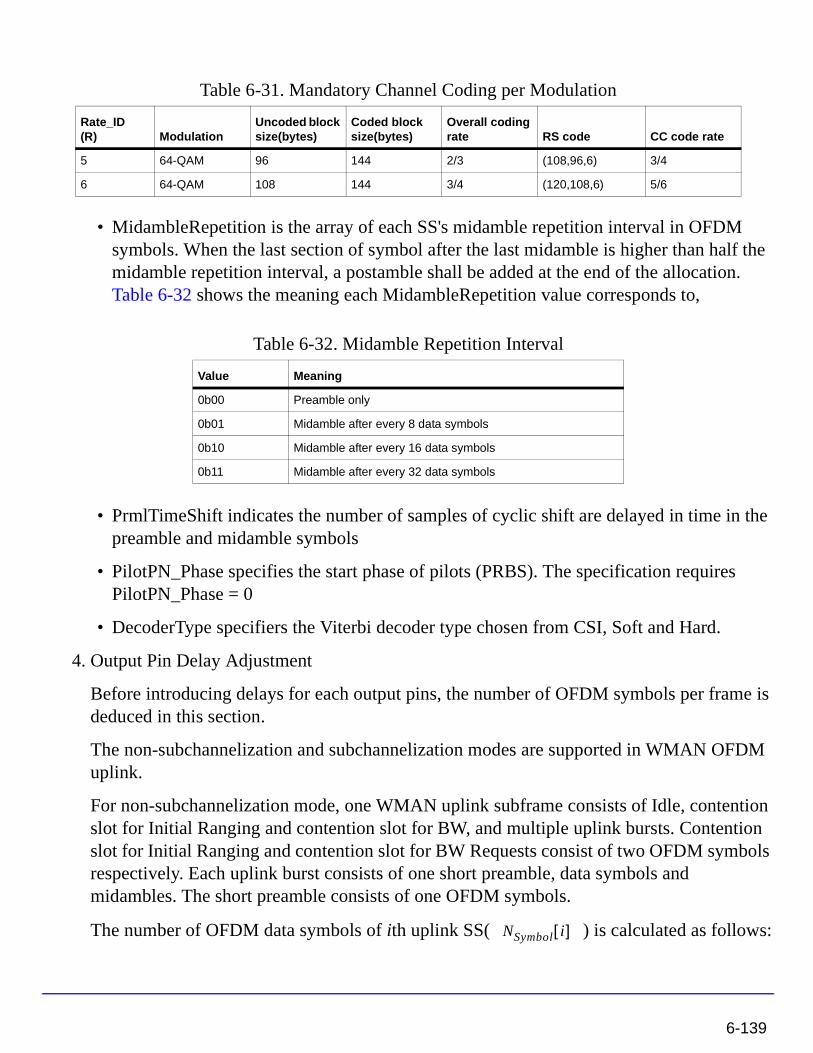
• MidambleRepetition is the array of each SS's midamble repetition interval in OFDM symbols. When the last section of symbol after the last midamble is higher than half the midamble repetition interval, a postamble shall be added at the end of the allocation. Table 6-32 shows the meaning each MidambleRepetition value corresponds to,
• PrmlTimeShift indicates the number of samples of cyclic shift are delayed in time in the preamble and midamble symbols
• PilotPN_Phase specifies the start phase of pilots (PRBS). The specification requires PilotPN_Phase = 0
• DecoderType specifiers the Viterbi decoder type chosen from CSI, Soft and Hard.
4. Output Pin Delay Adjustment
Before introducing delays for each output pins, the number of OFDM symbols per frame is deduced in this section.
The non-subchannelization and subchannelization modes are supported in WMAN OFDM uplink.
For non-subchannelization mode, one WMAN uplink subframe consists of Idle, contention slot for Initial Ranging and contention slot for BW, and multiple uplink bursts. Contention slot for Initial Ranging and contention slot for BW Requests consist of two OFDM symbols respectively. Each uplink burst consists of one short preamble, data symbols and midambles. The short preamble consists of one OFDM symbols.
The number of OFDM data symbols of ith uplink SS( ) is calculated as follows:
5 64-QAM 96 144 2/3 (108,96,6) 3/4
6 64-QAM 108 144 3/4 (120,108,6) 5/6
Table 6-32. Midamble Repetition Interval
Value Meaning
0b00 Preamble only
0b01 Midamble after every 8 data symbols
0b10 Midamble after every 16 data symbols
0b11 Midamble after every 32 data symbols
Table 6-31. Mandatory Channel Coding per Modulation
Rate_ID(R) Modulation
Uncoded block size(bytes)
Coded block size(bytes)
Overall coding rate RS code CC code rate
NSymbol i[ ]
6-139
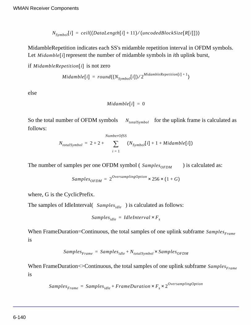
WMAN Receiver Components
MidambleRepetition indicates each SS's midamble repetition interval in OFDM symbols. Let represent the number of midamble symbols in ith uplink burst,
if is not zero
else
So the total number of OFDM symbols for the uplink frame is calculated as
follows:
The number of samples per one OFDM symbol ( ) is calculated as:
where, G is the CyclicPrefix.
The samples of IdleInterval( ) is calculated as follows:
When FrameDuration=Continuous, the total samples of one uplink subframe
is
When FrameDuration<>Continuous, the total samples of one uplink subframe
is
NSymbol i[ ] ceil DataLength i[ ] 11+( ) uncodedBlockSize R i[ ][ ]( )⁄( )=
Midamble i[ ]
MidambleRepetition i[ ]
Midamble i[ ] round NSymbol i[ ]( ) 2MidambleRepetition i[ ] 1+⁄( )=
Midamble i[ ] 0=
NtotalSymbol
NtotalSymbol 2 2 NSymbol i[ ] 1 Midamble i[ ]+ +( )i 1=
NumberOfSS
∑+ +=
SamplesOFDM
SamplesOFDM 2OversamplingOption
256× 1 G+( )×=
Samplesidle
Samplesidle IdleInterval Fs×=
SamplesFrame
SamplesFrame Samplesidle NtotalSymbol SamplesOFDM×+=
SamplesFrame
SamplesFrame Samplesidle FrameDuration Fs× 2OversamplingOption×+=
6-140
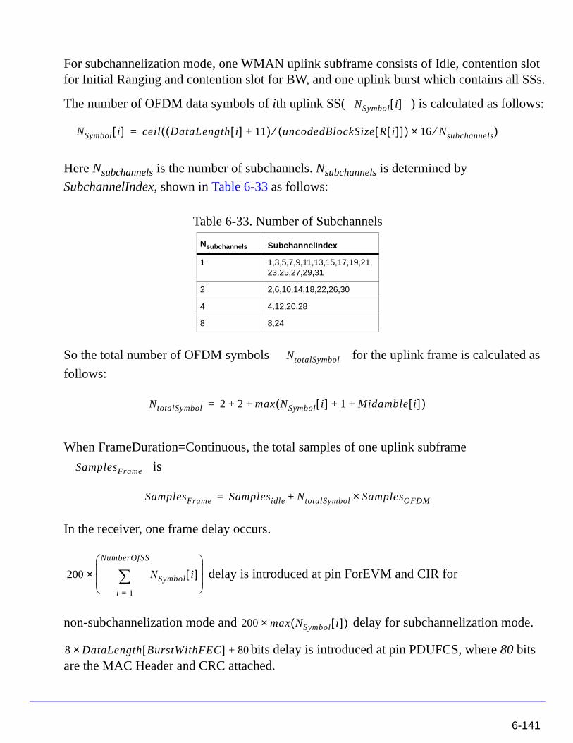
For subchannelization mode, one WMAN uplink subframe consists of Idle, contention slot for Initial Ranging and contention slot for BW, and one uplink burst which contains all SSs.
The number of OFDM data symbols of ith uplink SS( ) is calculated as follows:
Here Nsubchannels is the number of subchannels. Nsubchannels is determined by
SubchannelIndex, shown in Table 6-33 as follows:
So the total number of OFDM symbols for the uplink frame is calculated as
follows:
When FrameDuration=Continuous, the total samples of one uplink subframe
is
In the receiver, one frame delay occurs.
delay is introduced at pin ForEVM and CIR for
non-subchannelization mode and delay for subchannelization mode.
bits delay is introduced at pin PDUFCS, where 80 bits are the MAC Header and CRC attached.
Table 6-33. Number of Subchannels
Nsubchannels SubchannelIndex
1 1,3,5,7,9,11,13,15,17,19,21,23,25,27,29,31
2 2,6,10,14,18,22,26,30
4 4,12,20,28
8 8,24
NSymbol i[ ]
NSymbol i[ ] ceil DataLength i[ ] 11+( ) uncodedBlockSize R i[ ][ ]( )⁄ 16 Nsubchannels⁄×( )=
NtotalSymbol
NtotalSymbol 2 2 max NSymbol i[ ] 1 Midamble i[ ]+ +( )+ +=
SamplesFrame
SamplesFrame Samplesidle NtotalSymbol SamplesOFDM×+=
200 NSymbol i[ ]i 1=
NumberOfSS
∑
×
200 max NSymbol i[ ]( )×
8 DataLength BurstWithFEC[ ]× 80+
6-141
WMAN Receiver Components
bits delay is introduced at pin PSDU.
References
[1] IEEE Std 802.16-2004, Part 16: Air Interface for Fixed Broadband Wireless Access Systems, Section 8.3 WirelessMAN-OFDM PHY, October 1, 2004.
[2] IEEE P802.16-2004/Cor1/D5, Corrigendum to IEEE Standard for Local and Metropolitan Area Networks - Part 16: Air Interface for Fixed Broadband Wireless Access Systems, Sept. 2005.
8 DataLength BurstWithFEC[ ]×
6-142
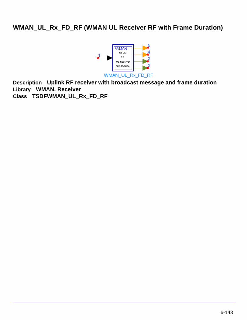
WMAN_UL_Rx_FD_RF (WMAN UL Receiver RF with Frame Duration)
Description Uplink RF receiver with broadcast message and frame durationLibrary WMAN, ReceiverClass TSDFWMAN_UL_Rx_FD_RF
6-143
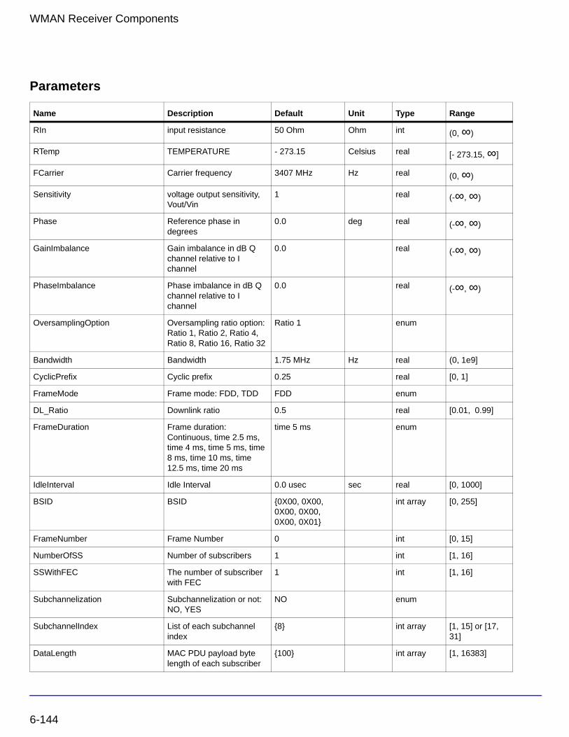
WMAN Receiver Components
Parameters
Name Description Default Unit Type Range
RIn input resistance 50 Ohm Ohm int (0, ∞)
RTemp TEMPERATURE - 273.15 Celsius real [- 273.15, ∞]
FCarrier Carrier frequency 3407 MHz Hz real (0, ∞)
Sensitivity voltage output sensitivity, Vout/Vin
1 real (-∞, ∞)
Phase Reference phase in degrees
0.0 deg real (-∞, ∞)
GainImbalance Gain imbalance in dB Q channel relative to I channel
0.0 real (-∞, ∞)
PhaseImbalance Phase imbalance in dB Q channel relative to I channel
0.0 real (-∞, ∞)
OversamplingOption Oversampling ratio option: Ratio 1, Ratio 2, Ratio 4, Ratio 8, Ratio 16, Ratio 32
Ratio 1 enum
Bandwidth Bandwidth 1.75 MHz Hz real (0, 1e9]
CyclicPrefix Cyclic prefix 0.25 real [0, 1]
FrameMode Frame mode: FDD, TDD FDD enum
DL_Ratio Downlink ratio 0.5 real [0.01, 0.99]
FrameDuration Frame duration: Continuous, time 2.5 ms, time 4 ms, time 5 ms, time 8 ms, time 10 ms, time 12.5 ms, time 20 ms
time 5 ms enum
IdleInterval Idle Interval 0.0 usec sec real [0, 1000]
BSID BSID {0X00, 0X00, 0X00, 0X00, 0X00, 0X01}
int array [0, 255]
FrameNumber Frame Number 0 int [0, 15]
NumberOfSS Number of subscribers 1 int [1, 16]
SSWithFEC The number of subscriber with FEC
1 int [1, 16]
Subchannelization Subchannelization or not: NO, YES
NO enum
SubchannelIndex List of each subchannel index
{8} int array [1, 15] or [17, 31]
DataLength MAC PDU payload byte length of each subscriber
{100} int array [1, 16383]
6-144
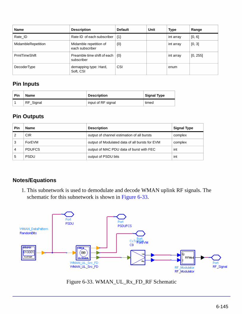
Pin Inputs
Pin Outputs
Notes/Equations
1. This subnetwork is used to demodulate and decode WMAN uplink RF signals. The schematic for this subnetwork is shown in Figure 6-33.
Figure 6-33. WMAN_UL_Rx_FD_RF Schematic
Rate_ID Rate ID of each subscriber {1} int array [0, 6]
MidambleRepetition Midamble repetition of each subscriber
{0} int array [0, 3]
PrmlTimeShift Preamble time shift of each subscriber
{0} int array [0, 255]
DecoderType demapping type: Hard, Soft, CSI
CSI enum
Pin Name Description Signal Type
1 RF_Signal input of RF signal timed
Pin Name Description Signal Type
2 CIR output of channel estimation of all bursts complex
3 ForEVM output of Modulated data of all bursts for EVM complex
4 PDUFCS output of MAC PDU data of burst with FEC int
5 PSDU output of PSDU bits int
Name Description Default Unit Type Range
6-145
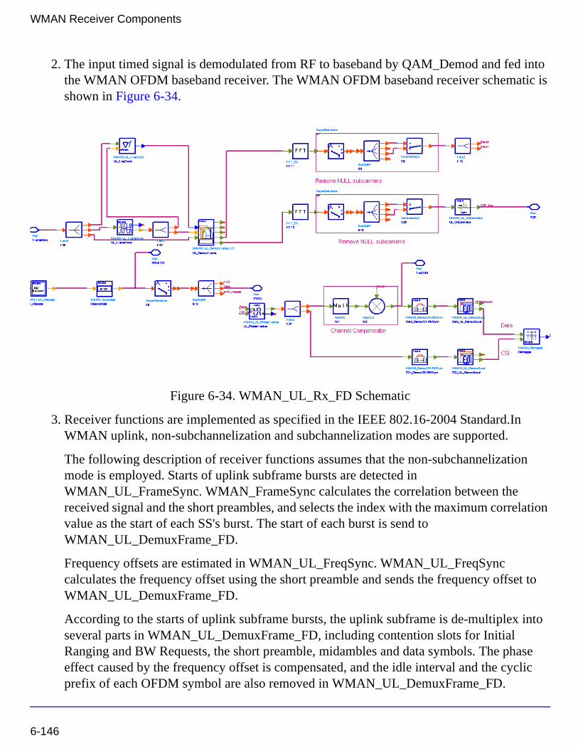
WMAN Receiver Components
2. The input timed signal is demodulated from RF to baseband by QAM_Demod and fed into the WMAN OFDM baseband receiver. The WMAN OFDM baseband receiver schematic is shown in Figure 6-34.
Figure 6-34. WMAN_UL_Rx_FD Schematic
3. Receiver functions are implemented as specified in the IEEE 802.16-2004 Standard.In WMAN uplink, non-subchannelization and subchannelization modes are supported.
The following description of receiver functions assumes that the non-subchannelization mode is employed. Starts of uplink subframe bursts are detected in WMAN_UL_FrameSync. WMAN_FrameSync calculates the correlation between the received signal and the short preambles, and selects the index with the maximum correlation value as the start of each SS's burst. The start of each burst is send to WMAN_UL_DemuxFrame_FD.
Frequency offsets are estimated in WMAN_UL_FreqSync. WMAN_UL_FreqSync calculates the frequency offset using the short preamble and sends the frequency offset to WMAN_UL_DemuxFrame_FD.
According to the starts of uplink subframe bursts, the uplink subframe is de-multiplex into several parts in WMAN_UL_DemuxFrame_FD, including contention slots for Initial Ranging and BW Requests, the short preamble, midambles and data symbols. The phase effect caused by the frequency offset is compensated, and the idle interval and the cyclic prefix of each OFDM symbol are also removed in WMAN_UL_DemuxFrame_FD.
6-146
The data symbols, short preamble and midambles are passed into frequency domain through FFT transformation. The short preamble and midambles used for channel estimation, where channel estimation is done in WMAN_UL_ChEstimation.
WMAN_UL_ChEstimation uses the preambles and midambles to get the complex channel response coefficients (CIR). First the CIRs in the even subcarriers are counted by a simple divider, then the CIRs in the odd subcarriers are interpolated by a FIR filter. Finally WMAN_UL_ChEstimation duplicates the estimated CIRs the number of data symbols. The channel estimation result is output at pin CIR.
WMAN_UL_PhaseTracker is used to track the phase caused by doppler shift by comparing the previous CIRs and the CIRs in pilot subcarriers of the current data symbols. Then the estimated CIR is updated according to the phase offset detected.
After the estimated CIRs going through WMAN_UL_PhaseTracker, they are used for channel equalization which is implemented by a simple divider. The equalized data are output at pin ForEVM for EVM measurements.
Then the pilot subcarriers are removed from the equalized signals in WMAN_DemuxOFDMSym, and the burst with FEC-encoded is separated from the bursts chain in WMAN_DemuxBurst which is send to WMAN_Demapper. In WMAN_Demapper, Three demapper types (CSI, Soft and Hard) are supported.
After FEC decoding, de-interleaving, de-scrambling, the MAC PDU data are achieved, which are divided into MAC header, MAC PDU payloads and CRC. The MAC PDU and its payloads are output at pin PDUFCS and PSDU respectively.
In subchannelization mode, because all SSs share one burst using different subchannels, only one start of uplink subframe burst will be detected in WMAN_UL_FrameSync. And WMAN_UL_FreqSync will do nothing, resulting in no frequency offset compensation is needed in WMAN_DemuxFrame. In WMAN_UL_ChEstimation, no interpolation is needed because the CIRs in all data subcarriers are available for each subchannel. The process after WMAN_UL_DemuxBurst is the same as that in non-subchannelization mode.
4. Parameter Details
• RIn is the RF input source resistance.
• RTemp is the RF output source resistance temperature in Celsius and sets the noise density in the RF output signal to (k(RTemp+273.15)) Watts/Hz, where k is Boltzmann's constant.
• FCarrier parameter is the RF signal frequency.
6-147
WMAN Receiver Components
• GainImbalance and PhaseImbalance add certain impairments to the ideal output RF signal. Impairments are added as described here.
The unimpaired RF I and Q envelope voltages have gain and phase imbalance applied. The RF is given by:
where V1(t) is the in-phase RF envelope, V2(t) is the quadrature phase RF envelope, g is the gain imbalance:
and, (in degrees) is the phase imbalance.
• OversamplingOption specifies the oversampling ratio of the transmission signal. OversamplingOption is Ratio 1, Ratio 2, ... , Ratio 32, which indicates the oversampling ratio of transmission signal is 1, 2, ... , 32.
• Bandwidth defines the nominal bandwidth. According to the specification, the supported nominal bandwidths are 1.25MHz, 1.5MHz, 1.75 MHz, 2.5 MHz, 3 MHz, 3.5 MHz, 5 MHz, 5.5 MHz, 6 MHz, 7 MHz, 10 MHz, 11 MHz, 12 MHz, 14 MHz, 15 MHz, 20 MHz, 24 MHz and 28 MHz. This parameter type is floating. Other bandwidth except the above is also supported. The sampling frequency implemented in the design is decided by Bandwidth, OversamplingOption and related sampling factor as follows:
The sampling factors are listed in Table 6-34.
Table 6-34. Sampling Factor Requirement
sampling factor n bandwidth
8/7 For channel bandwidths that are a multiple of 1.75 MHz
86/75 else for channel bandwidths that are a multiple of 1.5 MHz
144/125 else for channel bandwidths that are a multiple of 1.25 MHz
316/275 else for channel bandwidths that are a multiple of 2.75 MHz
V3 t( ) A V1 t( ) ωct( )cos gV2 t( ) ωctΦπ180---------+
sin– =
g 10
GainImbalance20
-----------------------------------------
=
φ
Fs floor n Bandwidth×( ) 8000⁄( ) 8000×=
6-148
• CyclicPrefix specifies the ratio of guard time (cyclic prefix) to useful symbol period, whose range is from 0 to 1.
• FrameMode is determines the generated frame is FDD mode or TDD mode. If FDD mode, the full frame is used to transmit this uplink signal source. If TDD mode, the frame is used to transmit both downlink and uplink signal source, the first part is for downlink transmission and the second part is for uplink transmission. These two parts are controlled by the DL_Ratio parameter in one frame.
• DL_Ratio is used to split one frame into two parts. When FrameMode=TDD and FrameDuration<>Continuous, it is active. The first part (duration is FrameDuration*DL_Ratio) is to transmit downlink (filled by zeros) and the rest part (second part) is to transmit uplink source.
• FrameDuration specifies the frame type. It’s type is enum. There are 8 cases (Continuous, time 2.5 ms, time 4 ms, time 5 ms, time 8 ms, time 10 ms, time 12.5 ms and time 20 ms). When FrameDuration =Continuous, the uplink source is transmitted continuously (without frame structure) and both FrameMode and DL_Ratio parameters are inactive. When FrameDuration <>Continuous, the uplink source is transmitted frame by frame (with frame structure) and both FrameMode and DL_Ratio parameters are active.
• IdleInterval specifies the time of idle interval between two consecutive subframes. The default value is 0.0 µsec.
• FrameNumber, BSID are used to generate the scrambler UL initialization vector.
• NumberOfSS specifies the number of active subscribes (SS).
• SSWithFEC specifies the SS which goes through FEC encoding and decoding.
• Subchannelization is the boolean value to indicate whether subchannelization is employed or not.
• SubchannelIndex is the array of each SS's subchannel index allocated. This parameter is valid only when Subchannelization is set to YES. Note that the values in SubchannelIndex should be in ascending order.
• DataLength is the array of each SS's MAC PDU payload byte length.
57/50 else for channel bandwidths that are a multiple of 2.0 MHz
8/7 else for channel bandwidths not otherwise specified
Table 6-34. Sampling Factor Requirement
sampling factor n bandwidth
6-149
WMAN Receiver Components
• Rate_ID is the array of each SS's Rate ID, whose range is from 0 to 6. DataLength and Rate_ID determine the number of data symbols per SS. Data-rate-dependent parameters (modulation, coding rate, coded bytes/uncoded bytes per OFDM symbol) will be set according to Table 6-35, which is based on the specification.
• MidambleRepetition is the array of each SS's midamble repetition interval in OFDM symbols. When the last section of symbol after the last midamble is higher than half the midamble repetition interval, a postamble shall be added at the end of the allocation. Table 6-36 shows the meaning each MidambleRepetition value corresponds to,
• PrmlTimeShift indicates the number of samples of cyclic shift are delayed in time in the preamble and midamble symbols.
• DecoderType specifiers the Viterbi decoder type chosen from CSI, Soft and Hard.
5. Output Pin Delay Adjustment
Before introducing delays for each output pins, the number of OFDM symbols per frame is deduced in this section.
The non-subchannelization and subchannelization modes are supported in WMAN OFDM uplink.
Table 6-35. Mandatory Channel Coding per Modulation
Rate_ID(R) Modulation
Uncoded block size(bytes)
Coded block size(bytes)
Overall coding rate RS code CC code rate
0 BPSK 12 24 1/2 (12,12,0) 1/2
1 QPSK 24 48 1/2 (32,24,4) 2/3
2 QPSK 36 48 3/4 (40,36,2) 5/6
3 16-QAM 48 96 1/2 (64,48,8) 2/3
4 16-QAM 72 96 3/4 (80,72,4) 5/6
5 64-QAM 96 144 2/3 (108,96,6) 3/4
6 64-QAM 108 144 3/4 (120,108,6) 5/6
Table 6-36. Midamble Repetition Interval
Value Meaning
0b00 Preamble only
0b01 Midamble after every 8 data symbols
0b10 Midamble after every 16 data symbols
0b11 Midamble after every 32 data symbols
6-150
For non-subchannelization mode, one WMAN uplink subframe consists of Idle, contention slot for Initial Ranging and contention slot for BW, and multiple uplink bursts. Contention slot for Initial Ranging and contention slot for BW Requests consist of two OFDM symbols respectively. Each uplink burst consists of one short preamble, data symbols and midambles. The short preamble consists of one OFDM symbols.
The number of OFDM data symbols of ith uplink SS( ) is calculated as follows:
MidambleRepetition indicates each SS's midamble repetition interval in OFDM symbols. Let represent the number of midamble symbols in ith uplink burst,
if is not zero
else
So the total number of OFDM symbols for the uplink frame is calculated as
follows:
The number of samples per one OFDM symbol ( ) is calculated as:
where, G is the CyclicPrefix.
The samples of IdleInterval( ) is calculated as follows:
NSymbol i[ ]
NSymbol i[ ] ceil DataLength i[ ] 11+( ) uncodedBlockSize R i[ ][ ]( )⁄( )=
Midamble i[ ]
Midamble i[ ] round NSymbol i[ ]( ) 2MidambleRepetition i[ ] 1+⁄( )=
MidambleRepetition i[ ]
Midamble i[ ] 0=
NtotalSymbol
NtotalSymbol 2 2 NSymbol i[ ] 1 Midamble i[ ]+ +( )i 1=
NumberOfSS
∑+ +=
SamplesOFDM
SamplesOFDM 2OversamplingOption
256× 1 G+( )×=
Samplesidle
Samplesidle IdleInterval Fs×=
6-151
WMAN Receiver Components
When FrameDuration=Continuous, the total samples of one uplink subframe
is
When FrameDuration<>Continuous, the total samples of one uplink subframe
is
For subchannelization mode, one WMAN uplink subframe consists of Idle, contention slot for Initial Ranging and contention slot for BW, and one uplink burst which contains all SSs.
The number of OFDM data symbols of ith uplink SS( ) is calculated as follows:
Here Nsubchannels is the number of subchannels. Nsubchannels is determined by
SubchannelIndex, shown in Table 6-37 as follows:
So the total number of OFDM symbols for the uplink frame is calculated as
follows:
When FrameDuration=Continuous, the total samples of one uplink subframe
is
Table 6-37. Number of Subchannels
Nsubchannels SubchannelIndex
1 1,3,5,7,9,11,13,15,17,19,21,23,25,27,29,31
2 2,6,10,14,18,22,26,30
4 4,12,20,28
8 8,24
SamplesFrame
SamplesFrame Samplesidle NtotalSymbol SamplesOFDM×+=
SamplesFrame
SamplesFrame Samplesidle FrameDuration Fs× 2OversamplingOption×+=
NSymbol i[ ]
NSymbol i[ ] ceil DataLength i[ ] 11+( ) uncodedBlockSize R i[ ][ ]( )⁄ 16 Nsubchannels⁄×( )=
NtotalSymbol
NtotalSymbol 2 2 max NSymbol i[ ] 1 Midamble i[ ]+ +( )+ +=
SamplesFrame
SamplesFrame Samplesidle NtotalSymbol SamplesOFDM×+=
6-152
In the receiver, one frame delay occurs.
delay is introduced at pin ForEVM and CIR for
non-subchannelization mode and delay for subchannelization mode.
bits delay is introduced at pin PDUFCS, where 80 bits are the MAC Header and CRC attached.
bits delay is introduced at pin PSDU.
References
[1] IEEE Std 802.16-2004, Part 16: Air Interface for Fixed Broadband Wireless Access Systems, Section 8.3 WirelessMAN-OFDM PHY, October 1, 2004.
[2] IEEE P802.16-2004/Cor1/D5, Corrigendum to IEEE Standard for Local and Metropolitan Area Networks - Part 16: Air Interface for Fixed Broadband Wireless Access Systems, Sept. 2005.
200 NSymbol i[ ]i 1=
NumberOfSS
∑
×
200 max NSymbol i[ ]( )×
8 DataLength BurstWithFEC[ ]× 80+
8 DataLength BurstWithFEC[ ]×
6-153

WMAN Receiver Components
6-154
Chapter 7: WMAN Signal Source ComponentsThe signal source models provide models to generate downlink and uplink signal sources.
• WMAN_DCD: DCD generator
• WMAN_DLFP: Downlink frame prefix generator
• WMAN_DL_MAP: Downlink map generator
• WMAN_DL_Pilot: Downlink pilot generator
• WMAN_MACHeader: MAC header generator
• WMAN_Preamble: Preamble generator
• WMAN_UCD: UCD generator
• WMAN_UL_MAP: Uplink map generator
• WMAN_UL_Pilot: Uplink pilot generator
• WMAN_BrdcstMessage: Downlink broadcast message generator
• WMAN_DL_SignalSrc: Downlink baseband signal source
• WMAN_DL_SignalSrc_RF: Downlink RF signal source
• WMAN_DL_Src_FD: Downlink baseband signal source with frame duration
• WMAN_DL_Src_FD_RF: Downlink RF signal source with frame duration
• WMAN_DataPattern: Data pattern
• WMAN_MACPDU: MAC PDU generator
• WMAN_UL_SignalSrc: Uplink baseband signal source
• WMAN_UL_SignalSrc_RF: Uplink RF signal source
• WMAN_UL_Src_FD: Uplink baseband signal source with frame duration
• WMAN_UL_Src_FD_RF: Uplink RF signal source with frame duration
7-1
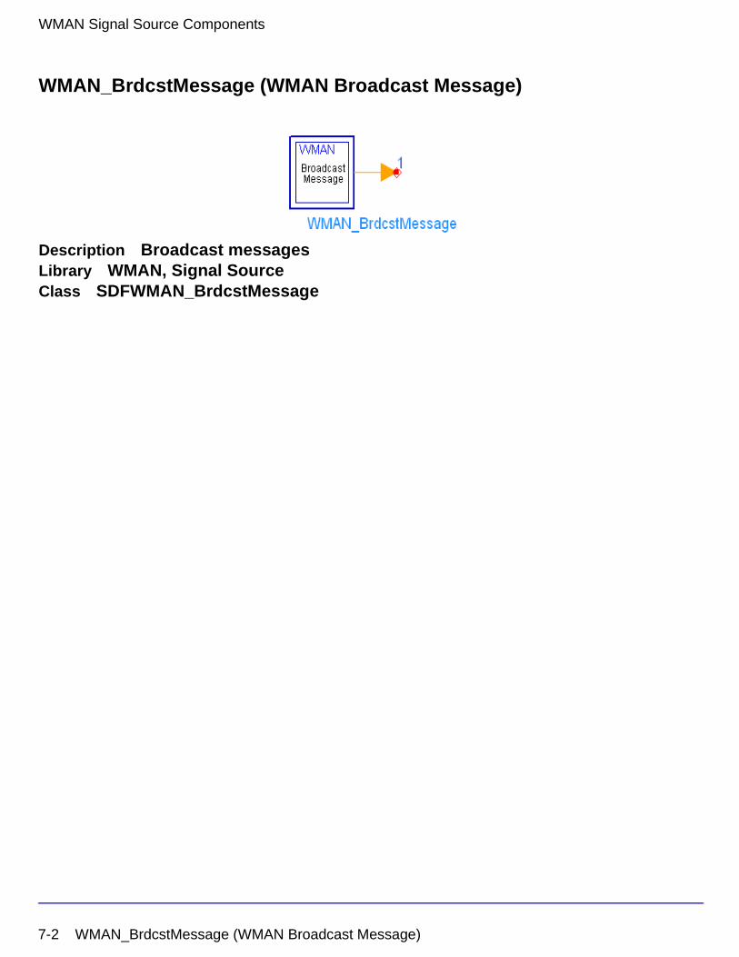
WMAN Signal Source Components
WMAN_BrdcstMessage (WMAN Broadcast Message)
Description Broadcast messagesLibrary WMAN, Signal SourceClass SDFWMAN_BrdcstMessage
7-2 WMAN_BrdcstMessage (WMAN Broadcast Message)
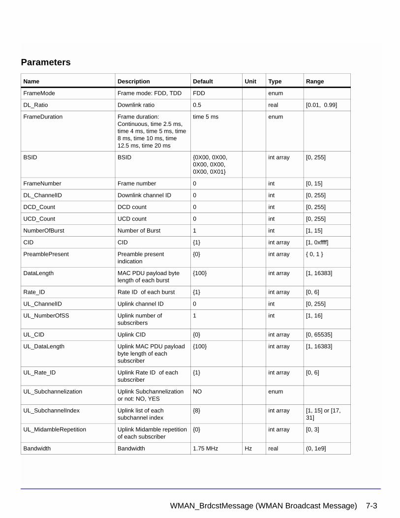
Parameters
Name Description Default Unit Type Range
FrameMode Frame mode: FDD, TDD FDD enum
DL_Ratio Downlink ratio 0.5 real [0.01, 0.99]
FrameDuration Frame duration: Continuous, time 2.5 ms, time 4 ms, time 5 ms, time 8 ms, time 10 ms, time 12.5 ms, time 20 ms
time 5 ms enum
BSID BSID {0X00, 0X00, 0X00, 0X00, 0X00, 0X01}
int array [0, 255]
FrameNumber Frame number 0 int [0, 15]
DL_ChannelID Downlink channel ID 0 int [0, 255]
DCD_Count DCD count 0 int [0, 255]
UCD_Count UCD count 0 int [0, 255]
NumberOfBurst Number of Burst 1 int [1, 15]
CID CID {1} int array [1, 0xffff]
PreamblePresent Preamble present indication
{0} int array { 0, 1 }
DataLength MAC PDU payload byte length of each burst
{100} int array [1, 16383]
Rate_ID Rate ID of each burst {1} int array [0, 6]
UL_ChannelID Uplink channel ID 0 int [0, 255]
UL_NumberOfSS Uplink number of subscribers
1 int [1, 16]
UL_CID Uplink CID {0} int array [0, 65535]
UL_DataLength Uplink MAC PDU payload byte length of each subscriber
{100} int array [1, 16383]
UL_Rate_ID Uplink Rate ID of each subscriber
{1} int array [0, 6]
UL_Subchannelization Uplink Subchannelization or not: NO, YES
NO enum
UL_SubchannelIndex Uplink list of each subchannel index
{8} int array [1, 15] or [17, 31]
UL_MidambleRepetition Uplink Midamble repetition of each subscriber
{0} int array [0, 3]
Bandwidth Bandwidth 1.75 MHz Hz real (0, 1e9]
WMAN_BrdcstMessage (WMAN Broadcast Message) 7-3
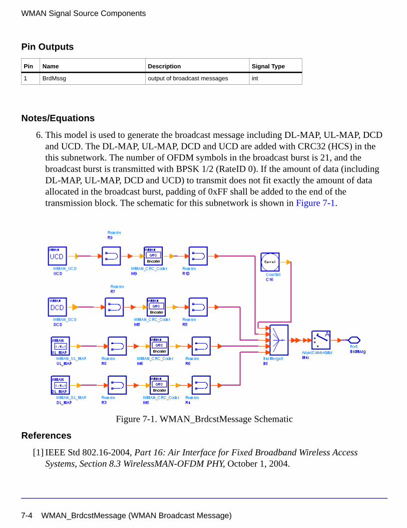
WMAN Signal Source Components
Pin Outputs
Notes/Equations
6. This model is used to generate the broadcast message including DL-MAP, UL-MAP, DCD and UCD. The DL-MAP, UL-MAP, DCD and UCD are added with CRC32 (HCS) in the this subnetwork. The number of OFDM symbols in the broadcast burst is 21, and the broadcast burst is transmitted with BPSK 1/2 (RateID 0). If the amount of data (including DL-MAP, UL-MAP, DCD and UCD) to transmit does not fit exactly the amount of data allocated in the broadcast burst, padding of 0xFF shall be added to the end of the transmission block. The schematic for this subnetwork is shown in Figure 7-1.
Figure 7-1. WMAN_BrdcstMessage Schematic
References
[1] IEEE Std 802.16-2004, Part 16: Air Interface for Fixed Broadband Wireless Access Systems, Section 8.3 WirelessMAN-OFDM PHY, October 1, 2004.
Pin Name Description Signal Type
1 BrdMssg output of broadcast messages int
7-4 WMAN_BrdcstMessage (WMAN Broadcast Message)
[2] IEEE P802.16-2004/Cor1/D5, Corrigendum to IEEE Standard for Local and Metropolitan Area Networks - Part 16: Air Interface for Fixed Broadband Wireless Access Systems, Sept. 2005.
WMAN_BrdcstMessage (WMAN Broadcast Message) 7-5
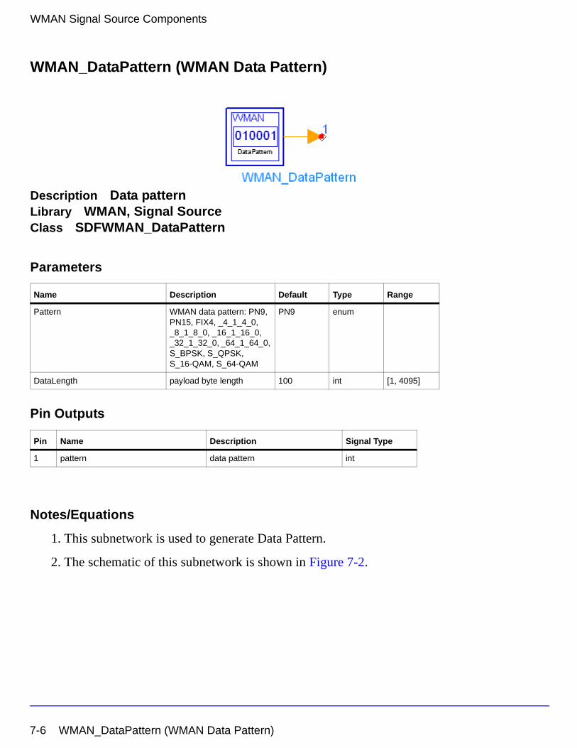
WMAN Signal Source Components
WMAN_DataPattern (WMAN Data Pattern)
Description Data patternLibrary WMAN, Signal SourceClass SDFWMAN_DataPattern
Parameters
Pin Outputs
Notes/Equations
1. This subnetwork is used to generate Data Pattern.
2. The schematic of this subnetwork is shown in Figure 7-2.
Name Description Default Type Range
Pattern WMAN data pattern: PN9, PN15, FIX4, _4_1_4_0, _8_1_8_0, _16_1_16_0, _32_1_32_0, _64_1_64_0, S_BPSK, S_QPSK, S_16-QAM, S_64-QAM
PN9 enum
DataLength payload byte length 100 int [1, 4095]
Pin Name Description Signal Type
1 pattern data pattern int
7-6 WMAN_DataPattern (WMAN Data Pattern)
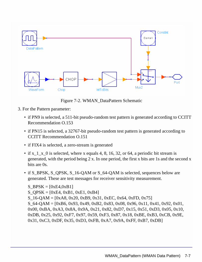
Figure 7-2. WMAN_DataPattern Schematic
3. For the Pattern parameter:
• if PN9 is selected, a 511-bit pseudo-random test pattern is generated according to CCITT Recommendation O.153
• if PN15 is selected, a 32767-bit pseudo-random test pattern is generated according to CCITT Recommendation O.151
• if FIX4 is selected, a zero-stream is generated
• if x_1_x_0 is selected, where x equals 4, 8, 16, 32, or 64, a periodic bit stream is generated, with the period being 2 x. In one period, the first x bits are 1s and the second x bits are 0s.
• if S_BPSK, S_QPSK, S_16-QAM or S_64-QAM is selected, sequences below are generated. These are test messages for receiver sensitivity measurement.
S_BPSK = [0xE4,0xB1]S_QPSK = [0xE4, 0xB1, 0xE1, 0xB4]S_16-QAM = [0xA8, 0x20, 0xB9, 0x31, 0xEC, 0x64, 0xFD, 0x75]S_64-QAM = [0xB6, 0x93, 0x49, 0xB2, 0x83, 0x08, 0x96, 0x11, 0x41, 0x92, 0x01, 0x00, 0xBA, 0xA3, 0x8A, 0x9A, 0x21, 0x82, 0xD7, 0x15, 0x51, 0xD3, 0x05, 0x10, 0xDB, 0x25, 0x92, 0xF7, 0x97, 0x59, 0xF3, 0x87, 0x18, 0xBE, 0xB3, 0xCB, 0x9E, 0x31, 0xC3, 0xDF, 0x35, 0xD3, 0xFB, 0xA7, 0x9A, 0xFF, 0xB7, 0xDB]
WMAN_DataPattern (WMAN Data Pattern) 7-7
WMAN Signal Source Components
References
[1] IEEE Std 802.16-2004, Part 16: Air Interface for Fixed Broadband Wireless Access Systems, Section 8.3 WirelessMAN-OFDM PHY, October 1, 2004.
[2] IEEE P802.16-2004/Cor1/D3, Corrigendum to IEEE Standard for Local and Metropolitan Area Networks - Part 16: Air Interface for Fixed Broadband Wireless Access Systems, May 2005.
[3] CCITT, Recommendation O.151(10/92).
[4] CCITT, Recommendation O.153(10/92).
7-8 WMAN_DataPattern (WMAN Data Pattern)
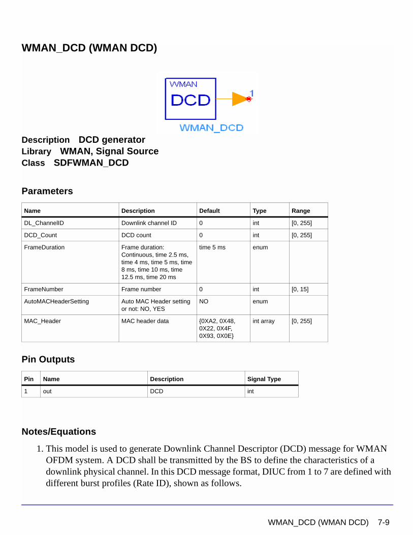
WMAN_DCD (WMAN DCD)
Description DCD generatorLibrary WMAN, Signal SourceClass SDFWMAN_DCD
Parameters
Pin Outputs
Notes/Equations
1. This model is used to generate Downlink Channel Descriptor (DCD) message for WMAN OFDM system. A DCD shall be transmitted by the BS to define the characteristics of a downlink physical channel. In this DCD message format, DIUC from 1 to 7 are defined with different burst profiles (Rate ID), shown as follows.
Name Description Default Type Range
DL_ChannelID Downlink channel ID 0 int [0, 255]
DCD_Count DCD count 0 int [0, 255]
FrameDuration Frame duration: Continuous, time 2.5 ms, time 4 ms, time 5 ms, time 8 ms, time 10 ms, time 12.5 ms, time 20 ms
time 5 ms enum
FrameNumber Frame number 0 int [0, 15]
AutoMACHeaderSetting Auto MAC Header setting or not: NO, YES
NO enum
MAC_Header MAC header data {0XA2, 0X48, 0X22, 0X4F, 0X93, 0X0E}
int array [0, 255]
Pin Name Description Signal Type
1 out DCD int
WMAN_DCD (WMAN DCD) 7-9
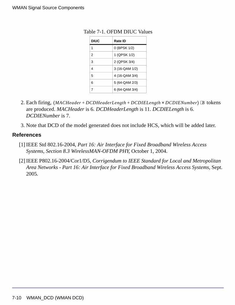
WMAN Signal Source Components
2. Each firing, tokens are produced. MACHeader is 6. DCDHeaderLength is 11. DCDIELength is 6. DCDIENumber is 7.
3. Note that DCD of the model generated does not include HCS, which will be added later.
References
[1] IEEE Std 802.16-2004, Part 16: Air Interface for Fixed Broadband Wireless Access Systems, Section 8.3 WirelessMAN-OFDM PHY, October 1, 2004.
[2] IEEE P802.16-2004/Cor1/D5, Corrigendum to IEEE Standard for Local and Metropolitan Area Networks - Part 16: Air Interface for Fixed Broadband Wireless Access Systems, Sept. 2005.
Table 7-1. OFDM DIUC Values
DIUC Rate ID
1 0 (BPSK 1/2)
2 1 (QPSK 1/2)
3 2 (QPSK 3/4)
4 3 (16-QAM 1/2)
5 4 (16-QAM 3/4)
6 5 (64-QAM 2/3)
7 6 (64-QAM 3/4)
MACHeader DCDHeaderLength DCDIELength DCDIENumber×+ +( ) 8⋅
7-10 WMAN_DCD (WMAN DCD)
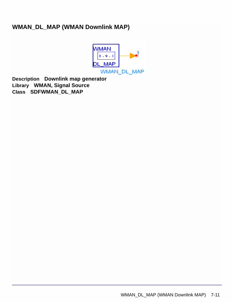
WMAN_DL_MAP (WMAN Downlink MAP)
Description Downlink map generatorLibrary WMAN, Signal SourceClass SDFWMAN_DL_MAP
WMAN_DL_MAP (WMAN Downlink MAP) 7-11
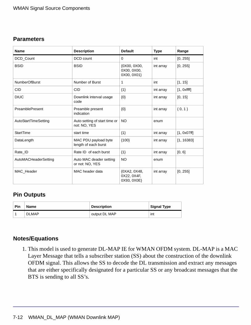
WMAN Signal Source Components
Parameters
Pin Outputs
Notes/Equations
1. This model is used to generate DL-MAP IE for WMAN OFDM system. DL-MAP is a MAC Layer Message that tells a subscriber station (SS) about the construction of the downlink OFDM signal. This allows the SS to decode the DL transmission and extract any messages that are either specifically designated for a particular SS or any broadcast messages that the BTS is sending to all SS’s.
Name Description Default Type Range
DCD_Count DCD count 0 int [0, 255]
BSID BSID {0X00, 0X00, 0X00, 0X00, 0X00, 0X01}
int array [0, 255]
NumberOfBurst Number of Burst 1 int [1, 15]
CID CID {1} int array [1, 0xffff]
DIUC Downlink interval usage code
{0} int array [0, 15]
PreamblePresent Preamble present indication
{0} int array { 0, 1 }
AutoStartTimeSetting Auto setting of start time or not: NO, YES
NO enum
StartTime start time {1} int array [1, 0x07ff]
DataLength MAC PDU payload byte length of each burst
{100} int array [1, 16383]
Rate_ID Rate ID of each burst {1} int array [0, 6]
AutoMACHeaderSetting Auto MAC deader setting or not: NO, YES
NO enum
MAC_Header MAC header data {0XA2, 0X48, 0X22, 0X4F, 0X93, 0X0E}
int array [0, 255]
Pin Name Description Signal Type
1 DLMAP output DL MAP int
7-12 WMAN_DL_MAP (WMAN Downlink MAP)
2. Each firing, tokens are
produced.
• MACHeader is 6.
DLMAPHeaderLength is 8.
DLMAPIELength is 4.
When , DLMAPIENumber is 1 which is the End MAP IE.
When , DLMAPIENumber is which are the End MAP IE and the data bursts excluding the first three data bursts.
The DL-MAP IEs for the first four bursts (Broadcast burst and the first three data bursts) are defined in the DLFP.
3. When AutoStartTimeSetting is set to YES, the starting time for each DL-MAP IE is calculated automatically. Otherwise the values in the parameter StartTime are used. When AutoMACHeaderSetting is set to YES, the MAC header is calculated automatically. Otherwise the values in the parameter MAC_Header are used.
4. Note that DL-MAP of the model generated does not include HCS, which will be added later.
References
[1] IEEE Std 802.16-2004, Part 16: Air Interface for Fixed Broadband Wireless Access Systems, Section 8.3 WirelessMAN-OFDM PHY, October 1, 2004.
[2] IEEE P802.16-2004/Cor1/D5, Corrigendum to IEEE Standard for Local and Metropolitan Area Networks - Part 16: Air Interface for Fixed Broadband Wireless Access Systems, Sept. 2005.
MACHeader DLMAPHeaderLength DLMAPIELength DLMAPIENumber×+ +( ) 8⋅
NumberOfBurst 4<
NumberOfBurst 4≥ NumberOfBurst 3– 1+
WMAN_DL_MAP (WMAN Downlink MAP) 7-13
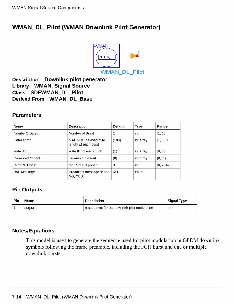
WMAN Signal Source Components
WMAN_DL_Pilot (WMAN Downlink Pilot Generator)
Description Downlink pilot generatorLibrary WMAN, Signal SourceClass SDFWMAN_DL_PilotDerived From WMAN_DL_Base
Parameters
Pin Outputs
Notes/Equations
1. This model is used to generate the sequence used for pilot modulation in OFDM downlink symbols following the frame preamble, including the FCH burst and one or multiple downlink bursts.
Name Description Default Type Range
NumberOfBurst Number of Burst 1 int [1, 16]
DataLength MAC PDU payload byte length of each burst
{100} int array [1, 16383]
Rate_ID Rate ID of each burst {1} int array [0, 6]
PreamblePresent Preamble present {0} int array {0, 1}
PilotPN_Phase the Pilot PN phase 0 int [0, 2047]
Brd_Message Broadcast message or not: NO, YES
NO enum
Pin Name Description Signal Type
1 output a sequence for the downlink pilot modulation int
7-14 WMAN_DL_Pilot (WMAN Downlink Pilot Generator)
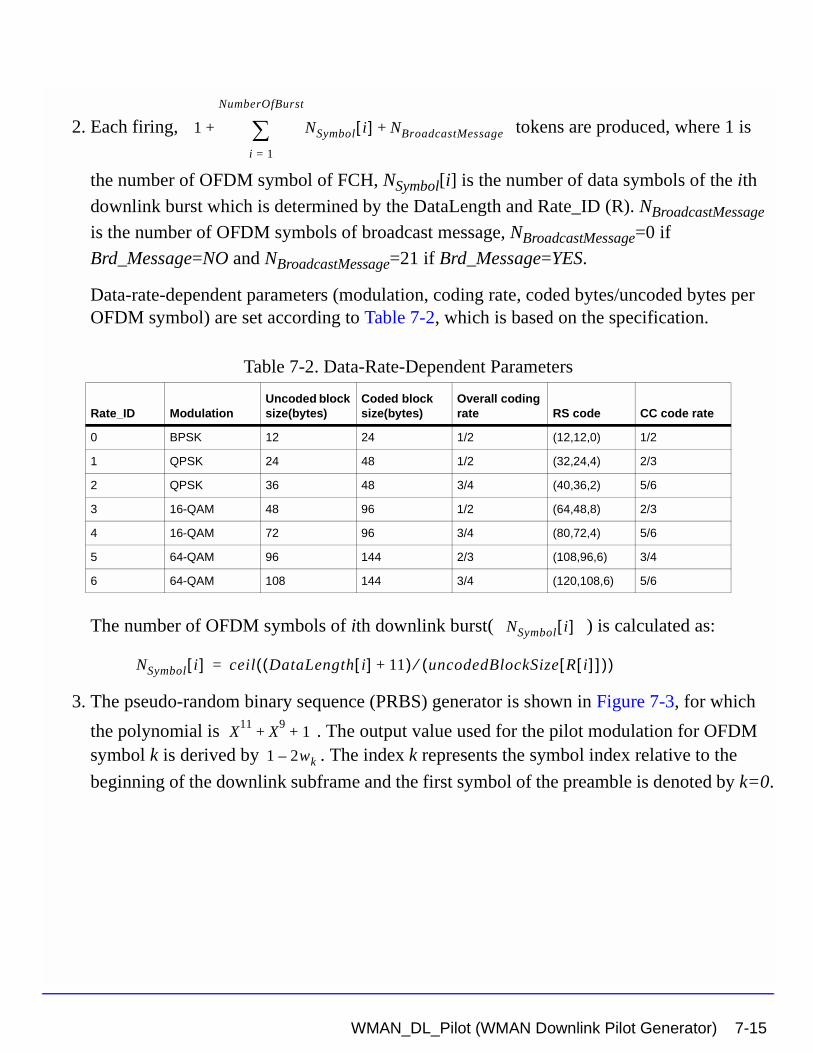
2. Each firing, tokens are produced, where 1 is
the number of OFDM symbol of FCH, NSymbol[i] is the number of data symbols of the ith
downlink burst which is determined by the DataLength and Rate_ID (R). NBroadcastMessage
is the number of OFDM symbols of broadcast message, NBroadcastMessage=0 if
Brd_Message=NO and NBroadcastMessage=21 if Brd_Message=YES.
Data-rate-dependent parameters (modulation, coding rate, coded bytes/uncoded bytes per OFDM symbol) are set according to Table 7-2, which is based on the specification.
The number of OFDM symbols of ith downlink burst( ) is calculated as:
3. The pseudo-random binary sequence (PRBS) generator is shown in Figure 7-3, for which
the polynomial is . The output value used for the pilot modulation for OFDM symbol k is derived by . The index k represents the symbol index relative to the
beginning of the downlink subframe and the first symbol of the preamble is denoted by k=0.
Table 7-2. Data-Rate-Dependent Parameters
Rate_ID ModulationUncoded block size(bytes)
Coded block size(bytes)
Overall coding rate RS code CC code rate
0 BPSK 12 24 1/2 (12,12,0) 1/2
1 QPSK 24 48 1/2 (32,24,4) 2/3
2 QPSK 36 48 3/4 (40,36,2) 5/6
3 16-QAM 48 96 1/2 (64,48,8) 2/3
4 16-QAM 72 96 3/4 (80,72,4) 5/6
5 64-QAM 96 144 2/3 (108,96,6) 3/4
6 64-QAM 108 144 3/4 (120,108,6) 5/6
1 NSymbol i[ ] NBroadcastMessage+
i 1=
NumberOfBurst
∑+
NSymbol i[ ]
NSymbol i[ ] ceil DataLength i[ ] 11+( ) uncodedBlockSize R i[ ][ ]( )⁄( )=
X11
X9
1+ +
1 2wk–
WMAN_DL_Pilot (WMAN Downlink Pilot Generator) 7-15
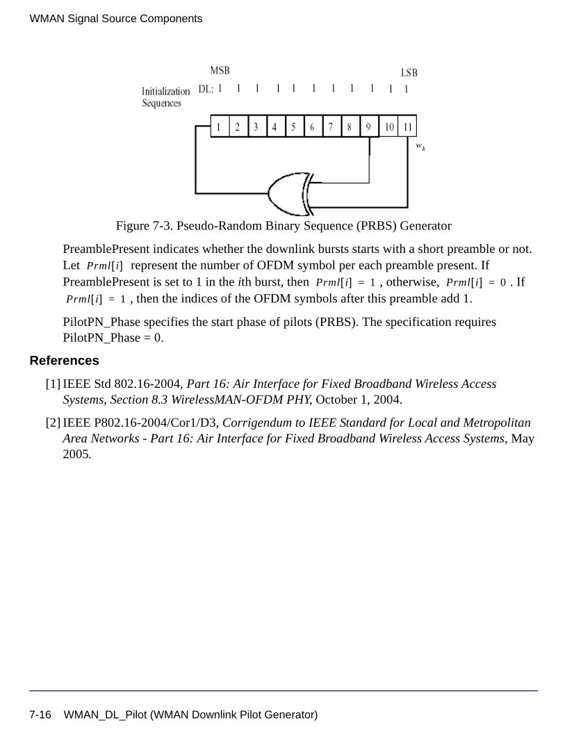
WMAN Signal Source Components
Figure 7-3. Pseudo-Random Binary Sequence (PRBS) Generator
PreamblePresent indicates whether the downlink bursts starts with a short preamble or not. Let represent the number of OFDM symbol per each preamble present. If PreamblePresent is set to 1 in the ith burst, then , otherwise, . If
, then the indices of the OFDM symbols after this preamble add 1.
PilotPN_Phase specifies the start phase of pilots (PRBS). The specification requires PilotPN_Phase = 0.
References
[1] IEEE Std 802.16-2004, Part 16: Air Interface for Fixed Broadband Wireless Access Systems, Section 8.3 WirelessMAN-OFDM PHY, October 1, 2004.
[2] IEEE P802.16-2004/Cor1/D3, Corrigendum to IEEE Standard for Local and Metropolitan Area Networks - Part 16: Air Interface for Fixed Broadband Wireless Access Systems, May 2005.
Prml i[ ]Prml i[ ] 1= Prml i[ ] 0=
Prml i[ ] 1=
7-16 WMAN_DL_Pilot (WMAN Downlink Pilot Generator)
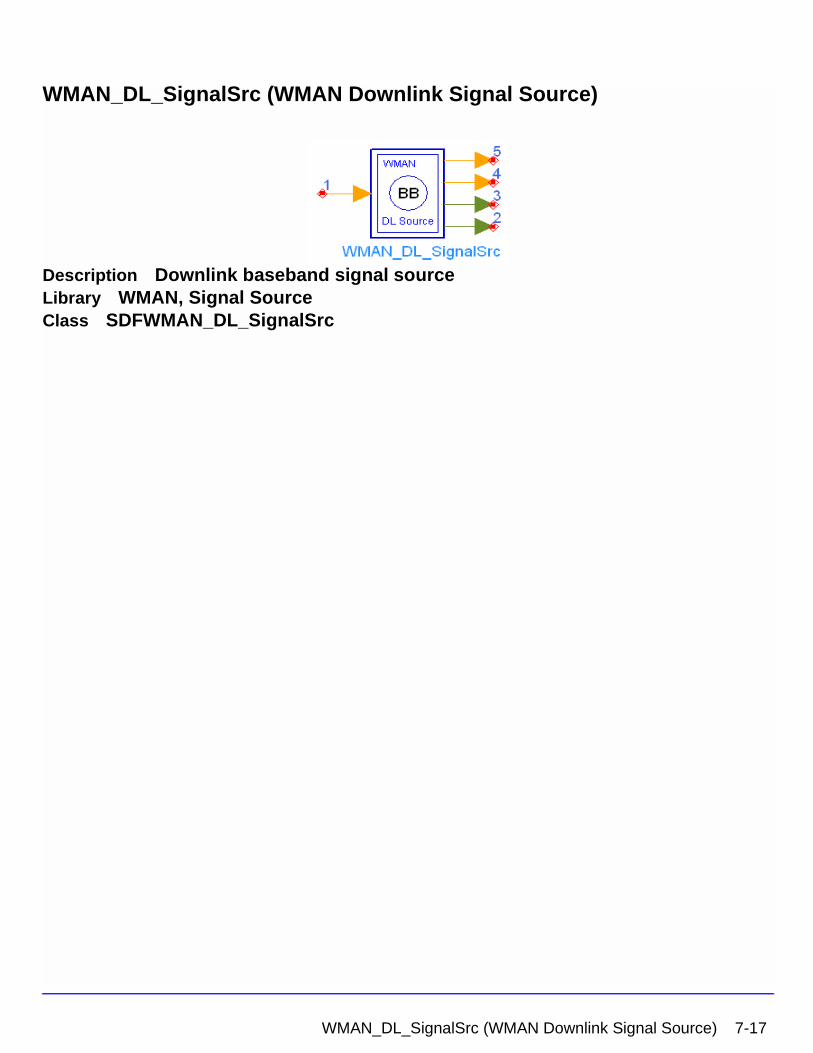
WMAN_DL_SignalSrc (WMAN Downlink Signal Source)
Description Downlink baseband signal sourceLibrary WMAN, Signal SourceClass SDFWMAN_DL_SignalSrc
WMAN_DL_SignalSrc (WMAN Downlink Signal Source) 7-17
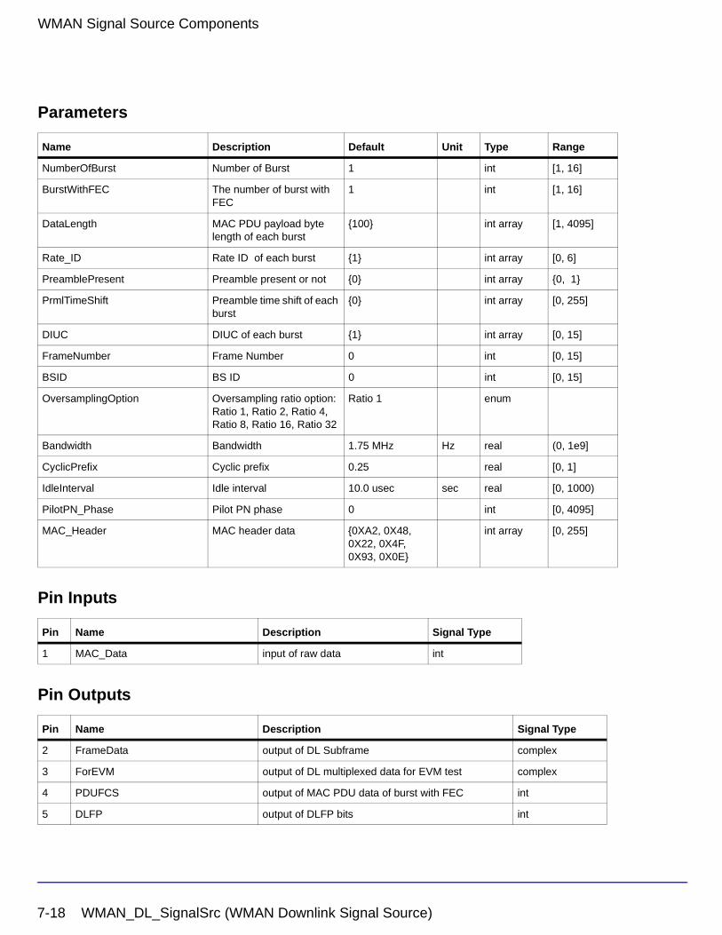
WMAN Signal Source Components
Parameters
Pin Inputs
Pin Outputs
Name Description Default Unit Type Range
NumberOfBurst Number of Burst 1 int [1, 16]
BurstWithFEC The number of burst with FEC
1 int [1, 16]
DataLength MAC PDU payload byte length of each burst
{100} int array [1, 4095]
Rate_ID Rate ID of each burst {1} int array [0, 6]
PreamblePresent Preamble present or not {0} int array {0, 1}
PrmlTimeShift Preamble time shift of each burst
{0} int array [0, 255]
DIUC DIUC of each burst {1} int array [0, 15]
FrameNumber Frame Number 0 int [0, 15]
BSID BS ID 0 int [0, 15]
OversamplingOption Oversampling ratio option: Ratio 1, Ratio 2, Ratio 4, Ratio 8, Ratio 16, Ratio 32
Ratio 1 enum
Bandwidth Bandwidth 1.75 MHz Hz real (0, 1e9]
CyclicPrefix Cyclic prefix 0.25 real [0, 1]
IdleInterval Idle interval 10.0 usec sec real [0, 1000)
PilotPN_Phase Pilot PN phase 0 int [0, 4095]
MAC_Header MAC header data {0XA2, 0X48, 0X22, 0X4F, 0X93, 0X0E}
int array [0, 255]
Pin Name Description Signal Type
1 MAC_Data input of raw data int
Pin Name Description Signal Type
2 FrameData output of DL Subframe complex
3 ForEVM output of DL multiplexed data for EVM test complex
4 PDUFCS output of MAC PDU data of burst with FEC int
5 DLFP output of DLFP bits int
7-18 WMAN_DL_SignalSrc (WMAN Downlink Signal Source)
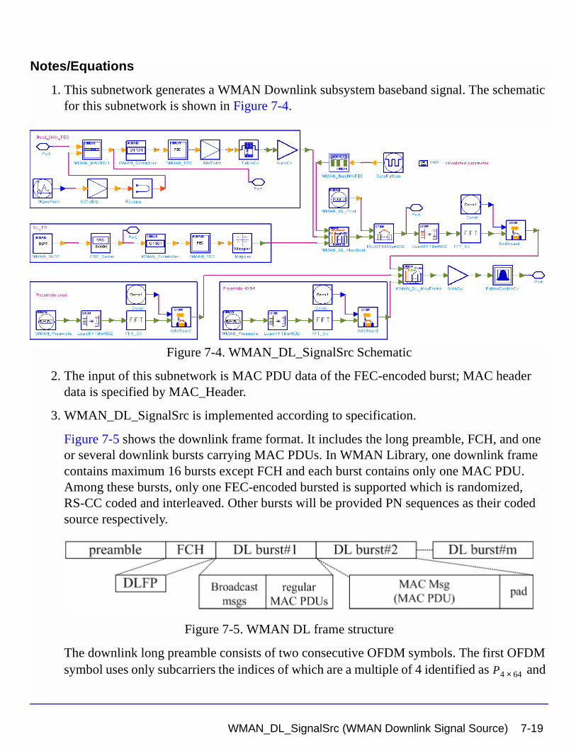
Notes/Equations
1. This subnetwork generates a WMAN Downlink subsystem baseband signal. The schematic for this subnetwork is shown in Figure 7-4.
Figure 7-4. WMAN_DL_SignalSrc Schematic
2. The input of this subnetwork is MAC PDU data of the FEC-encoded burst; MAC header data is specified by MAC_Header.
3. WMAN_DL_SignalSrc is implemented according to specification.
Figure 7-5 shows the downlink frame format. It includes the long preamble, FCH, and one or several downlink bursts carrying MAC PDUs. In WMAN Library, one downlink frame contains maximum 16 bursts except FCH and each burst contains only one MAC PDU. Among these bursts, only one FEC-encoded bursted is supported which is randomized, RS-CC coded and interleaved. Other bursts will be provided PN sequences as their coded source respectively.
Figure 7-5. WMAN DL frame structure
The downlink long preamble consists of two consecutive OFDM symbols. The first OFDM symbol uses only subcarriers the indices of which are a multiple of 4 identified as and P4 64×
WMAN_DL_SignalSrc (WMAN Downlink Signal Source) 7-19
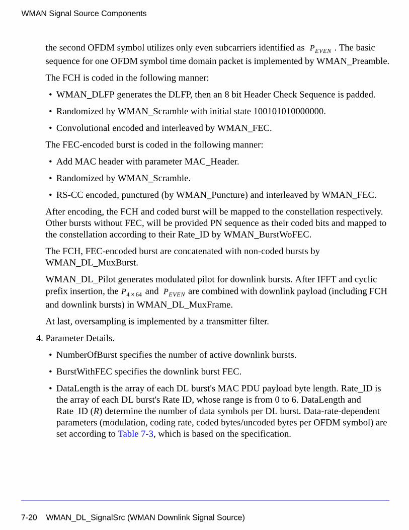
WMAN Signal Source Components
the second OFDM symbol utilizes only even subcarriers identified as . The basic
sequence for one OFDM symbol time domain packet is implemented by WMAN_Preamble.
The FCH is coded in the following manner:
• WMAN_DLFP generates the DLFP, then an 8 bit Header Check Sequence is padded.
• Randomized by WMAN_Scramble with initial state 100101010000000.
• Convolutional encoded and interleaved by WMAN_FEC.
The FEC-encoded burst is coded in the following manner:
• Add MAC header with parameter MAC_Header.
• Randomized by WMAN_Scramble.
• RS-CC encoded, punctured (by WMAN_Puncture) and interleaved by WMAN_FEC.
After encoding, the FCH and coded burst will be mapped to the constellation respectively. Other bursts without FEC, will be provided PN sequence as their coded bits and mapped to the constellation according to their Rate_ID by WMAN_BurstWoFEC.
The FCH, FEC-encoded burst are concatenated with non-coded bursts by WMAN_DL_MuxBurst.
WMAN_DL_Pilot generates modulated pilot for downlink bursts. After IFFT and cyclic prefix insertion, the and are combined with downlink payload (including FCH
and downlink bursts) in WMAN_DL_MuxFrame.
At last, oversampling is implemented by a transmitter filter.
4. Parameter Details.
• NumberOfBurst specifies the number of active downlink bursts.
• BurstWithFEC specifies the downlink burst FEC.
• DataLength is the array of each DL burst's MAC PDU payload byte length. Rate_ID is the array of each DL burst's Rate ID, whose range is from 0 to 6. DataLength and Rate_ID (R) determine the number of data symbols per DL burst. Data-rate-dependent parameters (modulation, coding rate, coded bytes/uncoded bytes per OFDM symbol) are set according to Table 7-3, which is based on the specification.
PEVEN
P4 64× PEVEN
7-20 WMAN_DL_SignalSrc (WMAN Downlink Signal Source)
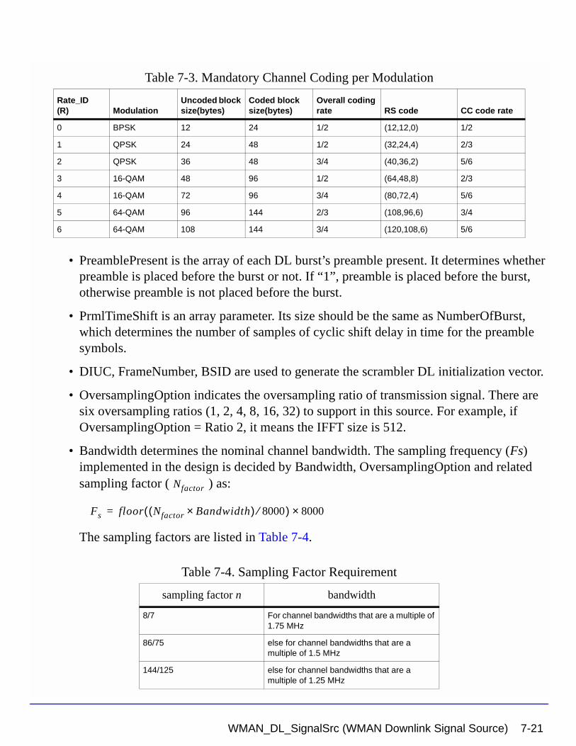
• PreamblePresent is the array of each DL burst’s preamble present. It determines whether preamble is placed before the burst or not. If “1”, preamble is placed before the burst, otherwise preamble is not placed before the burst.
• PrmlTimeShift is an array parameter. Its size should be the same as NumberOfBurst, which determines the number of samples of cyclic shift delay in time for the preamble symbols.
• DIUC, FrameNumber, BSID are used to generate the scrambler DL initialization vector.
• OversamplingOption indicates the oversampling ratio of transmission signal. There are six oversampling ratios (1, 2, 4, 8, 16, 32) to support in this source. For example, if OversamplingOption = Ratio 2, it means the IFFT size is 512.
• Bandwidth determines the nominal channel bandwidth. The sampling frequency (Fs) implemented in the design is decided by Bandwidth, OversamplingOption and related sampling factor ( ) as:
The sampling factors are listed in Table 7-4.
Table 7-3. Mandatory Channel Coding per Modulation
Rate_ID(R) Modulation
Uncoded block size(bytes)
Coded block size(bytes)
Overall coding rate RS code CC code rate
0 BPSK 12 24 1/2 (12,12,0) 1/2
1 QPSK 24 48 1/2 (32,24,4) 2/3
2 QPSK 36 48 3/4 (40,36,2) 5/6
3 16-QAM 48 96 1/2 (64,48,8) 2/3
4 16-QAM 72 96 3/4 (80,72,4) 5/6
5 64-QAM 96 144 2/3 (108,96,6) 3/4
6 64-QAM 108 144 3/4 (120,108,6) 5/6
Table 7-4. Sampling Factor Requirement
sampling factor n bandwidth
8/7 For channel bandwidths that are a multiple of 1.75 MHz
86/75 else for channel bandwidths that are a multiple of 1.5 MHz
144/125 else for channel bandwidths that are a multiple of 1.25 MHz
Nfactor
Fs floor Nfactor Bandwidth×( ) 8000⁄( ) 8000×=
WMAN_DL_SignalSrc (WMAN Downlink Signal Source) 7-21
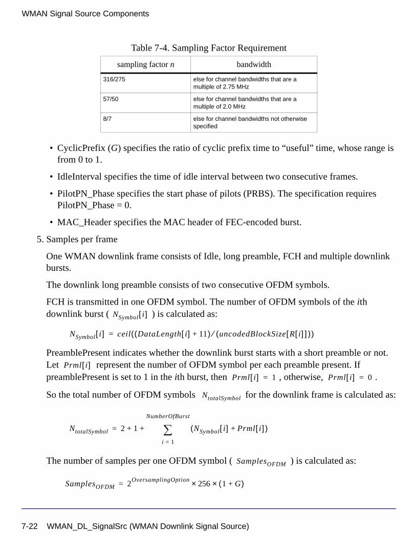
WMAN Signal Source Components
• CyclicPrefix (G) specifies the ratio of cyclic prefix time to “useful” time, whose range is from 0 to 1.
• IdleInterval specifies the time of idle interval between two consecutive frames.
• PilotPN_Phase specifies the start phase of pilots (PRBS). The specification requires PilotPN_Phase = 0.
• MAC_Header specifies the MAC header of FEC-encoded burst.
5. Samples per frame
One WMAN downlink frame consists of Idle, long preamble, FCH and multiple downlink bursts.
The downlink long preamble consists of two consecutive OFDM symbols.
FCH is transmitted in one OFDM symbol. The number of OFDM symbols of the ith downlink burst ( ) is calculated as:
PreamblePresent indicates whether the downlink burst starts with a short preamble or not. Let represent the number of OFDM symbol per each preamble present. If preamblePresent is set to 1 in the ith burst, then , otherwise, .
So the total number of OFDM symbols for the downlink frame is calculated as:
The number of samples per one OFDM symbol ( ) is calculated as:
316/275 else for channel bandwidths that are a multiple of 2.75 MHz
57/50 else for channel bandwidths that are a multiple of 2.0 MHz
8/7 else for channel bandwidths not otherwise specified
Table 7-4. Sampling Factor Requirement
sampling factor n bandwidth
NSymbol i[ ]
NSymbol i[ ] ceil DataLength i[ ] 11+( ) uncodedBlockSize R i[ ][ ]( )⁄( )=
Prml i[ ]Prml i[ ] 1= Prml i[ ] 0=
NtotalSymbol
NtotalSymbol 2 1 NSymbol i[ ] Prml i[ ]+( )i 1=
NumberOfBurst
∑+ +=
SamplesOFDM
SamplesOFDM 2OversamplingOption
256× 1 G+( )×=
7-22 WMAN_DL_SignalSrc (WMAN Downlink Signal Source)
The samples of IdleInterval( ) is calculated as:
So, the total samples of one downlink frame is
This model work on frame by frame. Each firing,
tokens are consumed at pin MAC_PDU, tokens are
produced at pin FrameData, tokens are produced at pin
ForEVM, tokens are produced at pin PSDUFCS, and 11 tokens are produced at pin DLFP.
6. Output delay
delay is introduced by the transmitter filter in the design WMAN_DL_SignalSrc, where the delay are equal to . Length is the parameter in the transmitter filter.
References
[1] IEEE Std 802.16-2004, Part 16: Air Interface for Fixed Broadband Wireless Access Systems, Section 8.3 WirelessMAN-OFDM PHY, October 1, 2004.
[2] IEEE P802.16-2004/Cor1/D3, Corrigendum to IEEE Standard for Local and Metropolitan Area Networks - Part 16: Air Interface for Fixed Broadband Wireless Access Systems, May 2005.
Samplesidle
Samplesidle IdleInterval 2OversamplingOption
Fs××=
SamplesFrame
SamplesFrame Samplesidle NtotalSymbol SamplesOFDM×+=
8 DataLength× SamplesFrame
200 1 NSymbol i[ ]i 1=
NumberOfBurst
∑+
×
8 DataLength× 80+
30 2oversamplingOption×
Length 1–( ) 2⁄
WMAN_DL_SignalSrc (WMAN Downlink Signal Source) 7-23
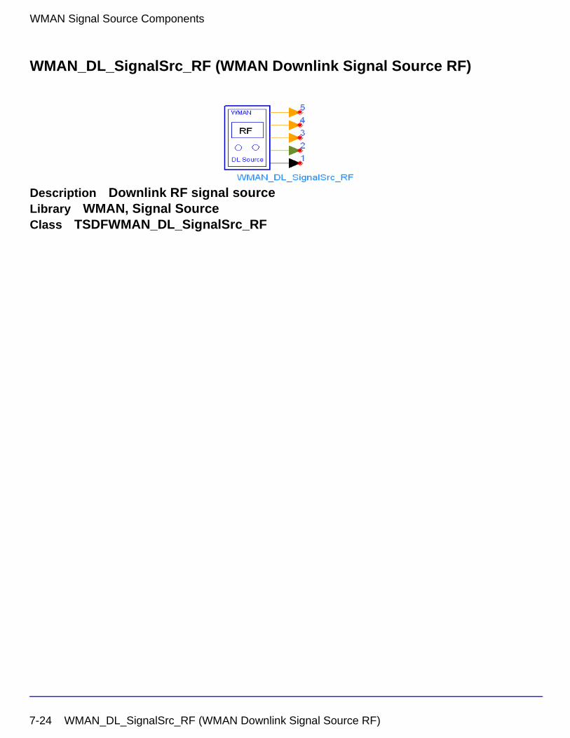
WMAN Signal Source Components
WMAN_DL_SignalSrc_RF (WMAN Downlink Signal Source RF)
Description Downlink RF signal sourceLibrary WMAN, Signal SourceClass TSDFWMAN_DL_SignalSrc_RF
7-24 WMAN_DL_SignalSrc_RF (WMAN Downlink Signal Source RF)
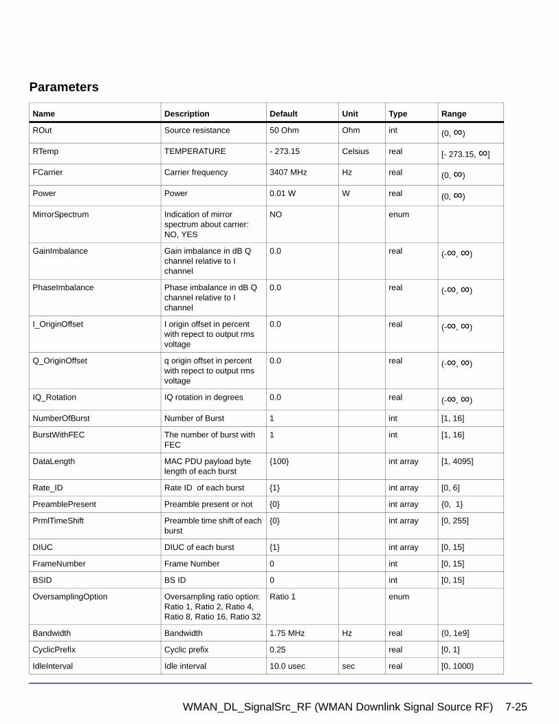
Parameters
Name Description Default Unit Type Range
ROut Source resistance 50 Ohm Ohm int (0, ∞)
RTemp TEMPERATURE - 273.15 Celsius real [- 273.15, ∞]
FCarrier Carrier frequency 3407 MHz Hz real (0, ∞)
Power Power 0.01 W W real (0, ∞)
MirrorSpectrum Indication of mirror spectrum about carrier: NO, YES
NO enum
GainImbalance Gain imbalance in dB Q channel relative to I channel
0.0 real (-∞, ∞)
PhaseImbalance Phase imbalance in dB Q channel relative to I channel
0.0 real (-∞, ∞)
I_OriginOffset I origin offset in percent with repect to output rms voltage
0.0 real (-∞, ∞)
Q_OriginOffset q origin offset in percent with repect to output rms voltage
0.0 real (-∞, ∞)
IQ_Rotation IQ rotation in degrees 0.0 real (-∞, ∞)
NumberOfBurst Number of Burst 1 int [1, 16]
BurstWithFEC The number of burst with FEC
1 int [1, 16]
DataLength MAC PDU payload byte length of each burst
{100} int array [1, 4095]
Rate_ID Rate ID of each burst {1} int array [0, 6]
PreamblePresent Preamble present or not {0} int array {0, 1}
PrmlTimeShift Preamble time shift of each burst
{0} int array [0, 255]
DIUC DIUC of each burst {1} int array [0, 15]
FrameNumber Frame Number 0 int [0, 15]
BSID BS ID 0 int [0, 15]
OversamplingOption Oversampling ratio option: Ratio 1, Ratio 2, Ratio 4, Ratio 8, Ratio 16, Ratio 32
Ratio 1 enum
Bandwidth Bandwidth 1.75 MHz Hz real (0, 1e9]
CyclicPrefix Cyclic prefix 0.25 real [0, 1]
IdleInterval Idle interval 10.0 usec sec real [0, 1000)
WMAN_DL_SignalSrc_RF (WMAN Downlink Signal Source RF) 7-25
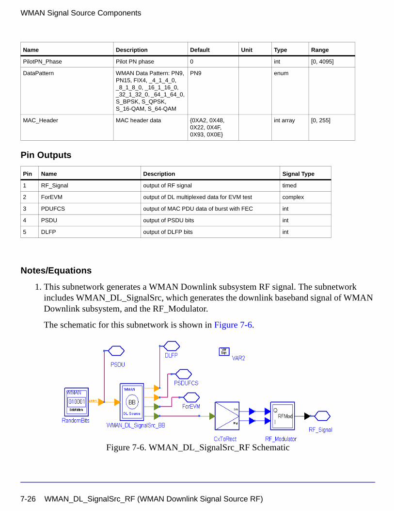
WMAN Signal Source Components
Pin Outputs
Notes/Equations
1. This subnetwork generates a WMAN Downlink subsystem RF signal. The subnetwork includes WMAN_DL_SignalSrc, which generates the downlink baseband signal of WMAN Downlink subsystem, and the RF_Modulator.
The schematic for this subnetwork is shown in Figure 7-6.
Figure 7-6. WMAN_DL_SignalSrc_RF Schematic
PilotPN_Phase Pilot PN phase 0 int [0, 4095]
DataPattern WMAN Data Pattern: PN9, PN15, FIX4, _4_1_4_0, _8_1_8_0, _16_1_16_0, _32_1_32_0, _64_1_64_0, S_BPSK, S_QPSK, S_16-QAM, S_64-QAM
PN9 enum
MAC_Header MAC header data {0XA2, 0X48, 0X22, 0X4F, 0X93, 0X0E}
int array [0, 255]
Pin Name Description Signal Type
1 RF_Signal output of RF signal timed
2 ForEVM output of DL multiplexed data for EVM test complex
3 PDUFCS output of MAC PDU data of burst with FEC int
4 PSDU output of PSDU bits int
5 DLFP output of DLFP bits int
Name Description Default Unit Type Range
7-26 WMAN_DL_SignalSrc_RF (WMAN Downlink Signal Source RF)
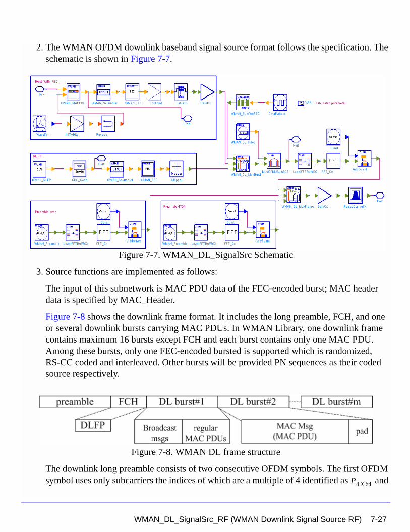
2. The WMAN OFDM downlink baseband signal source format follows the specification. The schematic is shown in Figure 7-7.
Figure 7-7. WMAN_DL_SignalSrc Schematic
3. Source functions are implemented as follows:
The input of this subnetwork is MAC PDU data of the FEC-encoded burst; MAC header data is specified by MAC_Header.
Figure 7-8 shows the downlink frame format. It includes the long preamble, FCH, and one or several downlink bursts carrying MAC PDUs. In WMAN Library, one downlink frame contains maximum 16 bursts except FCH and each burst contains only one MAC PDU. Among these bursts, only one FEC-encoded bursted is supported which is randomized, RS-CC coded and interleaved. Other bursts will be provided PN sequences as their coded source respectively.
Figure 7-8. WMAN DL frame structure
The downlink long preamble consists of two consecutive OFDM symbols. The first OFDM symbol uses only subcarriers the indices of which are a multiple of 4 identified as and P4 64×
WMAN_DL_SignalSrc_RF (WMAN Downlink Signal Source RF) 7-27
WMAN Signal Source Components
the second OFDM symbol utilizes only even subcarriers identified as . The basic
sequence for one OFDM symbol time domain packet is implemented by WMAN_Preamble.
The FCH is coded in the following manner:
• WMAN_DLFP generates the DLFP, then an 8 bit Header Check Sequence is padded.
• Randomized by WMAN_Scramble with initial state 100101010000000.
• Convolutional encoded and interleaved by WMAN_FEC.
The FEC-encoded burst is coded in the following manner:
• Add MAC header with parameter MAC_Header.
• Randomized by WMAN_Scramble.
• RS-CC encoded, punctured (by WMAN_Puncture) and interleaved by WMAN_FEC.
After encoding, the FCH and coded burst will be mapped to the constellation respectively. Other bursts without FEC, will be provided PN sequence as their coded bits and mapped to the constellation according to their Rate_ID by WMAN_BurstWoFEC.
The FCH, FEC-encoded burst are concatenated with non-coded bursts by WMAN_DL_MuxBurst.
WMAN_DL_Pilot generates modulated pilot for downlink bursts. After IFFT and cyclic prefix insertion, the and are combined with downlink payload (including
FCH and downlink bursts) in WMAN_DL_MuxFrame.
At last, oversampling is implemented by a transmitter filter.
4. Parameter Details.
• ROut is the RF output source resistance.
• RTemp is the RF output source resistance temperature in Celsius and sets the noise density in the RF output signal to (k(RTemp+273.15)) Watts/Hz, where k is Boltzmann's constant.
• FCarrier is the RF output signal frequency.
• Power is used to set the modulator output RF power. This is true for an ideal transmitted signal (no impairments added) or when small impairments are added. If large impairments are added to the signal (using GainImbalance, I_OriginOffset, and Q_OriginOffset parameters) the output RF power may be different from the value of the Power parameter.
PEVEN
P4 64× PEVEN
7-28 WMAN_DL_SignalSrc_RF (WMAN Downlink Signal Source RF)
• MirrorSpectrum is used to mirror the RF_out signal spectrum about the carrier. This is equivalent to conjugating the complex RF envelope voltage. Depending on the configuration and number of mixers in an RF transmitter, the RF output signal from hardware RF generators can be inverted. If such an RF signal is desired, set this parameter to YES.
• GainImbalance, PhaseImbalance, I_OriginOffset, Q_OriginOffset, and IQ_Rotation are used to add certain impairments to the ideal output RF signal. Impairments are added in the order described here.
The unimpaired RF I and Q envelope voltages have gain and phase imbalance applied. The RF is given by:
where A is a scaling factor based on the Power and ROut parameters specified by the user, VI(t) is the in-phase RF envelope, VQ(t) is the quadrature phase RF envelope, g is
the gain imbalance
and, (in degrees) is the phase imbalance.
Next, the signal VRF(t) is rotated by IQ_Rotation degrees. The I_OriginOffset and
Q_OriginOffset are then applied to the rotated signal. Note that the amounts specified are percentages with respect to the output rms voltage. The output rms voltage is given by sqrt(2×ROut×Power).
• NumberOfBurst specifies the number of active downlink bursts.
• BurstWithFEC specifies the downlink burst FEC.
• DataLength is the array of each DL burst's MAC PDU payload byte length. Rate_ID is the array of each DL burst's Rate ID, whose range is from 0 to 6. DataLength and Rate_ID (R) determine the number of data symbols per DL burst. Data-rate-dependent parameters (modulation, coding rate, coded bytes/uncoded bytes per OFDM symbol) are set according to Table 7-5, which is based on the specification.
VRF t( ) A VI t( ) ωct( )cos gVQ t( ) ωctΦπ180---------+
sin– =
g 10
GainImbalance20
-----------------------------------------
=
φ
WMAN_DL_SignalSrc_RF (WMAN Downlink Signal Source RF) 7-29
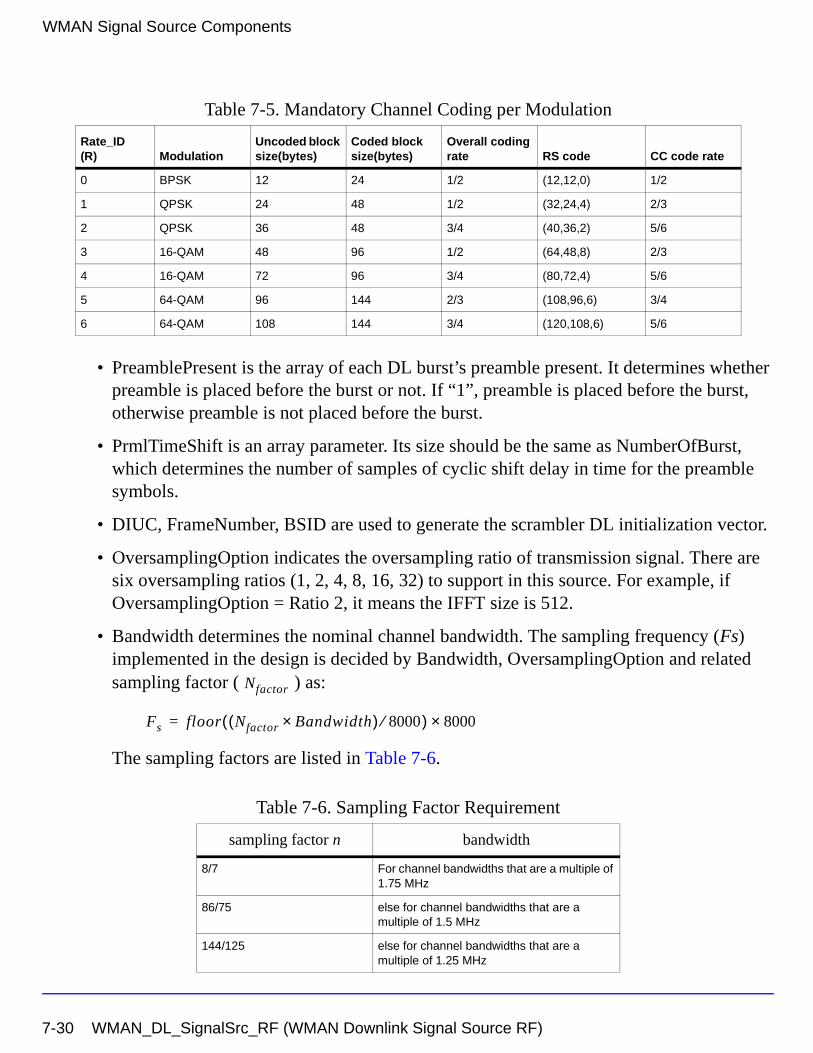
WMAN Signal Source Components
• PreamblePresent is the array of each DL burst’s preamble present. It determines whether preamble is placed before the burst or not. If “1”, preamble is placed before the burst, otherwise preamble is not placed before the burst.
• PrmlTimeShift is an array parameter. Its size should be the same as NumberOfBurst, which determines the number of samples of cyclic shift delay in time for the preamble symbols.
• DIUC, FrameNumber, BSID are used to generate the scrambler DL initialization vector.
• OversamplingOption indicates the oversampling ratio of transmission signal. There are six oversampling ratios (1, 2, 4, 8, 16, 32) to support in this source. For example, if OversamplingOption = Ratio 2, it means the IFFT size is 512.
• Bandwidth determines the nominal channel bandwidth. The sampling frequency (Fs) implemented in the design is decided by Bandwidth, OversamplingOption and related sampling factor ( ) as:
The sampling factors are listed in Table 7-6.
Table 7-5. Mandatory Channel Coding per Modulation
Rate_ID(R) Modulation
Uncoded block size(bytes)
Coded block size(bytes)
Overall coding rate RS code CC code rate
0 BPSK 12 24 1/2 (12,12,0) 1/2
1 QPSK 24 48 1/2 (32,24,4) 2/3
2 QPSK 36 48 3/4 (40,36,2) 5/6
3 16-QAM 48 96 1/2 (64,48,8) 2/3
4 16-QAM 72 96 3/4 (80,72,4) 5/6
5 64-QAM 96 144 2/3 (108,96,6) 3/4
6 64-QAM 108 144 3/4 (120,108,6) 5/6
Table 7-6. Sampling Factor Requirement
sampling factor n bandwidth
8/7 For channel bandwidths that are a multiple of 1.75 MHz
86/75 else for channel bandwidths that are a multiple of 1.5 MHz
144/125 else for channel bandwidths that are a multiple of 1.25 MHz
Nfactor
Fs floor Nfactor Bandwidth×( ) 8000⁄( ) 8000×=
7-30 WMAN_DL_SignalSrc_RF (WMAN Downlink Signal Source RF)
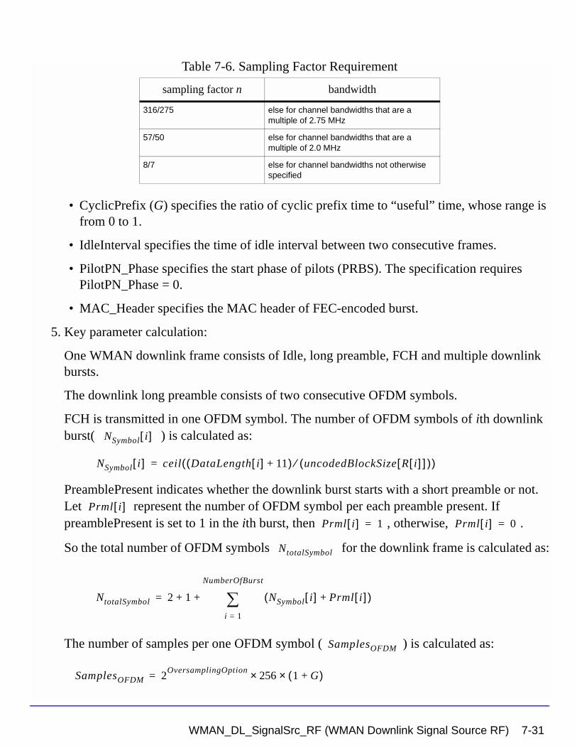
• CyclicPrefix (G) specifies the ratio of cyclic prefix time to “useful” time, whose range is from 0 to 1.
• IdleInterval specifies the time of idle interval between two consecutive frames.
• PilotPN_Phase specifies the start phase of pilots (PRBS). The specification requires PilotPN_Phase = 0.
• MAC_Header specifies the MAC header of FEC-encoded burst.
5. Key parameter calculation:
One WMAN downlink frame consists of Idle, long preamble, FCH and multiple downlink bursts.
The downlink long preamble consists of two consecutive OFDM symbols.
FCH is transmitted in one OFDM symbol. The number of OFDM symbols of ith downlink burst( ) is calculated as:
PreamblePresent indicates whether the downlink burst starts with a short preamble or not. Let represent the number of OFDM symbol per each preamble present. If preamblePresent is set to 1 in the ith burst, then , otherwise, .
So the total number of OFDM symbols for the downlink frame is calculated as:
The number of samples per one OFDM symbol ( ) is calculated as:
316/275 else for channel bandwidths that are a multiple of 2.75 MHz
57/50 else for channel bandwidths that are a multiple of 2.0 MHz
8/7 else for channel bandwidths not otherwise specified
Table 7-6. Sampling Factor Requirement
sampling factor n bandwidth
NSymbol i[ ]
NSymbol i[ ] ceil DataLength i[ ] 11+( ) uncodedBlockSize R i[ ][ ]( )⁄( )=
Prml i[ ]Prml i[ ] 1= Prml i[ ] 0=
NtotalSymbol
NtotalSymbol 2 1 NSymbol i[ ] Prml i[ ]+( )i 1=
NumberOfBurst
∑+ +=
SamplesOFDM
SamplesOFDM 2OversamplingOption
256× 1 G+( )×=
WMAN_DL_SignalSrc_RF (WMAN Downlink Signal Source RF) 7-31
WMAN Signal Source Components
The samples of IdleInterval( ) is calculated as:
So, the total samples of one downlink frame is
6. Output delay
delay is introduced by the transmitter filter in the design WMAN_DL_SignalSrc, where the delay are equal to . Length is the parameter in the transmitter filter.
References
[1] IEEE Std 802.16-2004, Part 16: Air Interface for Fixed Broadband Wireless Access Systems, Section 8.3 WirelessMAN-OFDM PHY, October 1, 2004.
[2] IEEE P802.16-2004/Cor1/D3, Corrigendum to IEEE Standard for Local and Metropolitan Area Networks - Part 16: Air Interface for Fixed Broadband Wireless Access Systems, May 2005.
Samplesidle
Samplesidle IdleInterval 2OversamplingOption
Fs××=
SamplesFrame
SamplesFrame Samplesidle NtotalSymbol SamplesOFDM×+=
30 2oversamplingOption×
Length 1–( ) 2⁄
7-32 WMAN_DL_SignalSrc_RF (WMAN Downlink Signal Source RF)
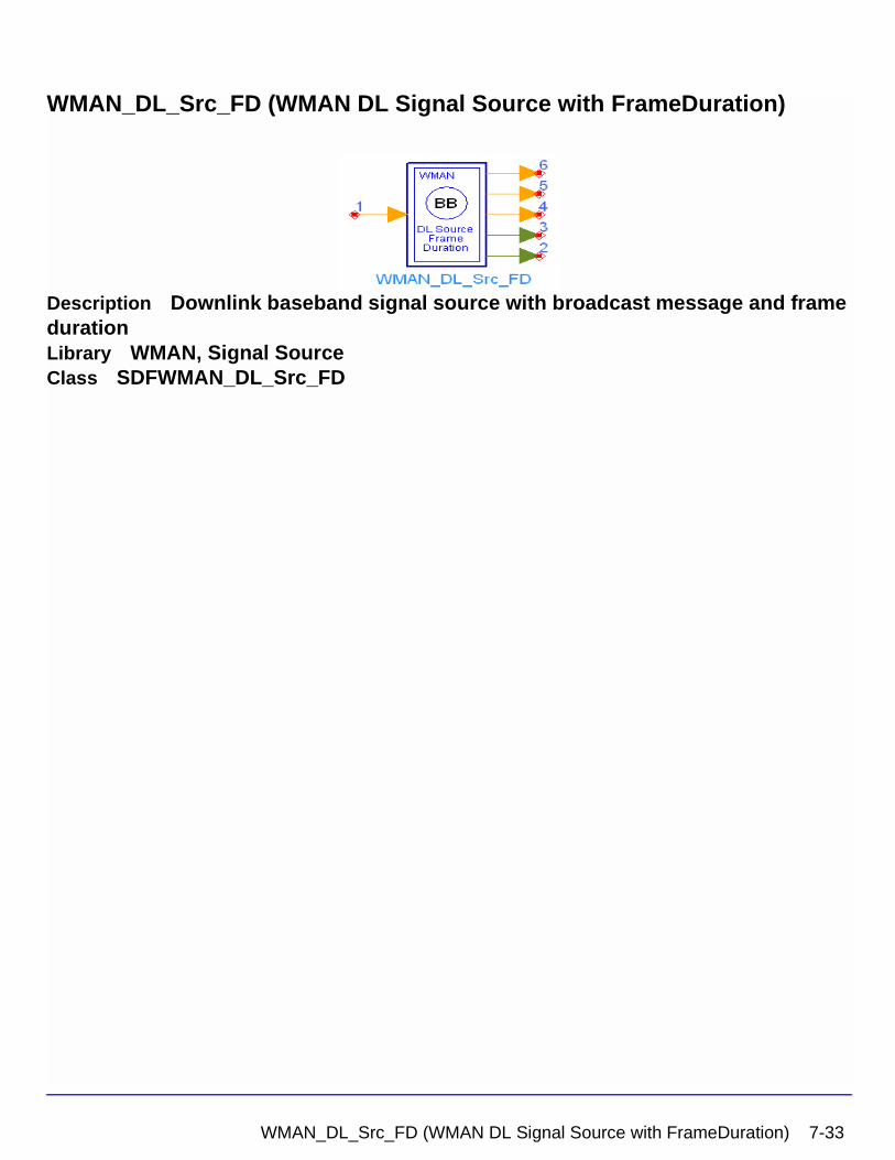
WMAN_DL_Src_FD (WMAN DL Signal Source with FrameDuration)
Description Downlink baseband signal source with broadcast message and frame durationLibrary WMAN, Signal SourceClass SDFWMAN_DL_Src_FD
WMAN_DL_Src_FD (WMAN DL Signal Source with FrameDuration) 7-33
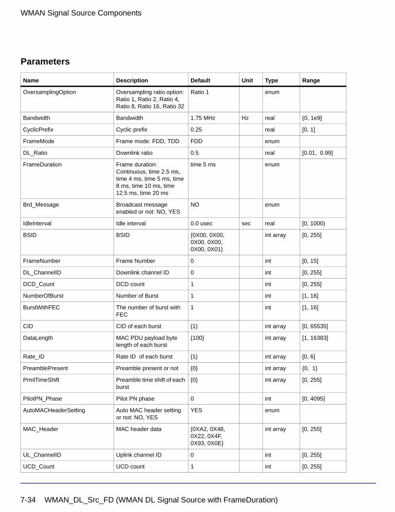
WMAN Signal Source Components
Parameters
Name Description Default Unit Type Range
OversamplingOption Oversampling ratio option: Ratio 1, Ratio 2, Ratio 4, Ratio 8, Ratio 16, Ratio 32
Ratio 1 enum
Bandwidth Bandwidth 1.75 MHz Hz real (0, 1e9]
CyclicPrefix Cyclic prefix 0.25 real [0, 1]
FrameMode Frame mode: FDD, TDD FDD enum
DL_Ratio Downlink ratio 0.5 real [0.01, 0.99]
FrameDuration Frame duration: Continuous, time 2.5 ms, time 4 ms, time 5 ms, time 8 ms, time 10 ms, time 12.5 ms, time 20 ms
time 5 ms enum
Brd_Message Broadcast message enabled or not: NO, YES
NO enum
IdleInterval Idle interval 0.0 usec sec real [0, 1000)
BSID BSID {0X00, 0X00, 0X00, 0X00, 0X00, 0X01}
int array [0, 255]
FrameNumber Frame Number 0 int [0, 15]
DL_ChannelID Downlink channel ID 0 int [0, 255]
DCD_Count DCD count 1 int [0, 255]
NumberOfBurst Number of Burst 1 int [1, 16]
BurstWithFEC The number of burst with FEC
1 int [1, 16]
CID CID of each burst {1} int array [0, 65535]
DataLength MAC PDU payload byte length of each burst
{100} int array [1, 16383]
Rate_ID Rate ID of each burst {1} int array [0, 6]
PreamblePresent Preamble present or not {0} int array {0, 1}
PrmlTimeShift Preamble time shift of each burst
{0} int array [0, 255]
PilotPN_Phase Pilot PN phase 0 int [0, 4095]
AutoMACHeaderSetting Auto MAC header setting or not: NO, YES
YES enum
MAC_Header MAC header data {0XA2, 0X48, 0X22, 0X4F, 0X93, 0X0E}
int array [0, 255]
UL_ChannelID Uplink channel ID 0 int [0, 255]
UCD_Count UCD count 1 int [0, 255]
7-34 WMAN_DL_Src_FD (WMAN DL Signal Source with FrameDuration)
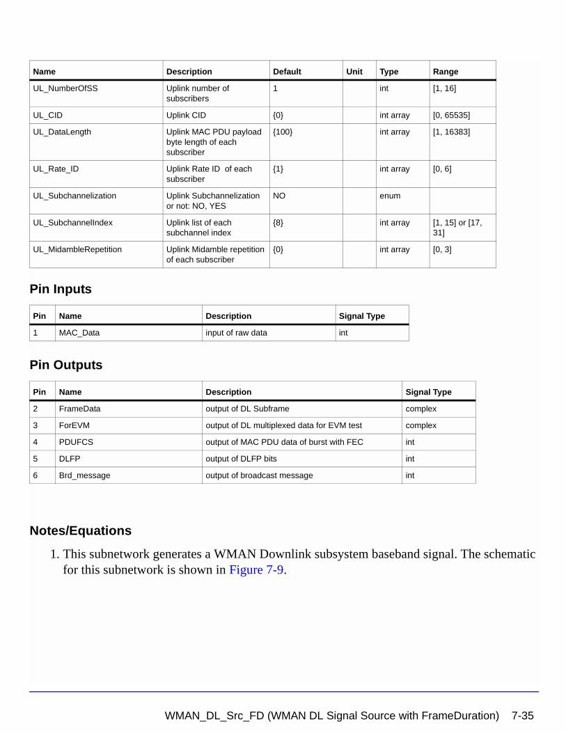
Pin Inputs
Pin Outputs
Notes/Equations
1. This subnetwork generates a WMAN Downlink subsystem baseband signal. The schematic for this subnetwork is shown in Figure 7-9.
UL_NumberOfSS Uplink number of subscribers
1 int [1, 16]
UL_CID Uplink CID {0} int array [0, 65535]
UL_DataLength Uplink MAC PDU payload byte length of each subscriber
{100} int array [1, 16383]
UL_Rate_ID Uplink Rate ID of each subscriber
{1} int array [0, 6]
UL_Subchannelization Uplink Subchannelization or not: NO, YES
NO enum
UL_SubchannelIndex Uplink list of each subchannel index
{8} int array [1, 15] or [17, 31]
UL_MidambleRepetition Uplink Midamble repetition of each subscriber
{0} int array [0, 3]
Pin Name Description Signal Type
1 MAC_Data input of raw data int
Pin Name Description Signal Type
2 FrameData output of DL Subframe complex
3 ForEVM output of DL multiplexed data for EVM test complex
4 PDUFCS output of MAC PDU data of burst with FEC int
5 DLFP output of DLFP bits int
6 Brd_message output of broadcast message int
Name Description Default Unit Type Range
WMAN_DL_Src_FD (WMAN DL Signal Source with FrameDuration) 7-35
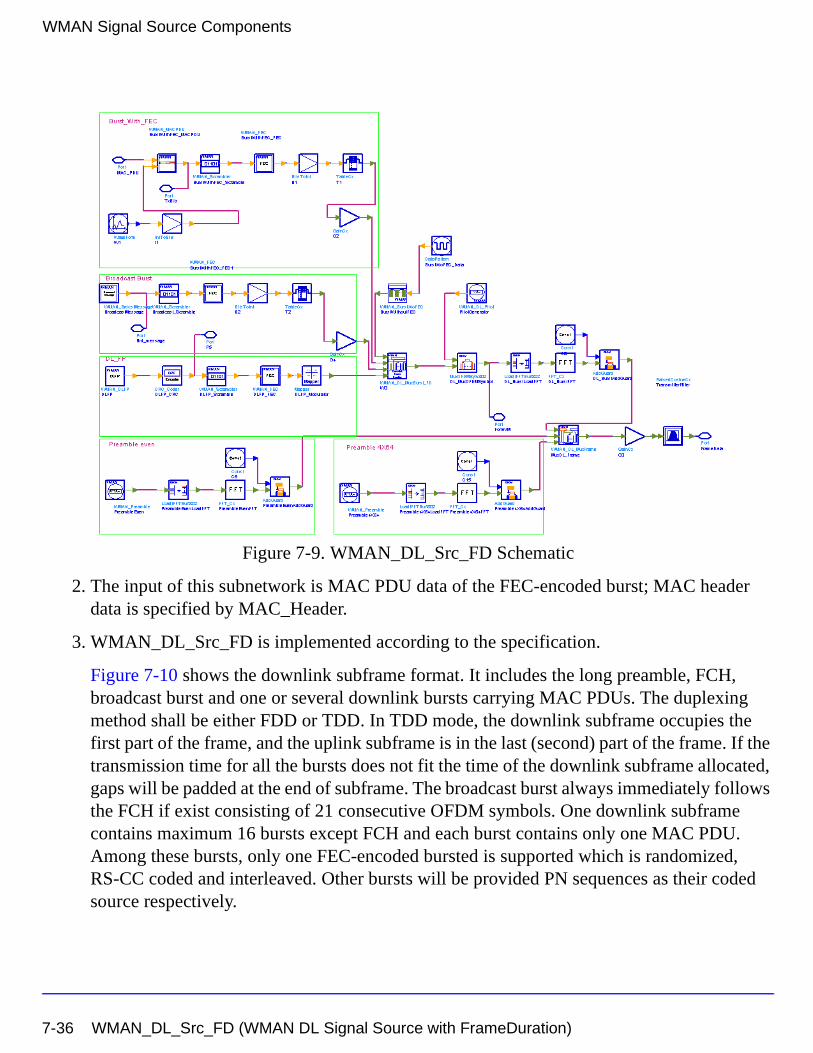
WMAN Signal Source Components
Figure 7-9. WMAN_DL_Src_FD Schematic
2. The input of this subnetwork is MAC PDU data of the FEC-encoded burst; MAC header data is specified by MAC_Header.
3. WMAN_DL_Src_FD is implemented according to the specification.
Figure 7-10 shows the downlink subframe format. It includes the long preamble, FCH, broadcast burst and one or several downlink bursts carrying MAC PDUs. The duplexing method shall be either FDD or TDD. In TDD mode, the downlink subframe occupies the first part of the frame, and the uplink subframe is in the last (second) part of the frame. If the transmission time for all the bursts does not fit the time of the downlink subframe allocated, gaps will be padded at the end of subframe. The broadcast burst always immediately follows the FCH if exist consisting of 21 consecutive OFDM symbols. One downlink subframe contains maximum 16 bursts except FCH and each burst contains only one MAC PDU. Among these bursts, only one FEC-encoded bursted is supported which is randomized, RS-CC coded and interleaved. Other bursts will be provided PN sequences as their coded source respectively.
7-36 WMAN_DL_Src_FD (WMAN DL Signal Source with FrameDuration)
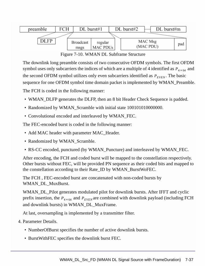
Figure 7-10. WMAN DL Subframe Structure
The downlink long preamble consists of two consecutive OFDM symbols. The first OFDM symbol uses only subcarriers the indices of which are a multiple of 4 identified as and
the second OFDM symbol utilizes only even subcarriers identified as . The basic
sequence for one OFDM symbol time domain packet is implemented by WMAN_Preamble.
The FCH is coded in the following manner:
• WMAN_DLFP generates the DLFP, then an 8 bit Header Check Sequence is padded.
• Randomized by WMAN_Scramble with initial state 100101010000000.
• Convolutional encoded and interleaved by WMAN_FEC.
The FEC-encoded burst is coded in the following manner:
• Add MAC header with parameter MAC_Header.
• Randomized by WMAN_Scramble.
• RS-CC encoded, punctured (by WMAN_Puncture) and interleaved by WMAN_FEC.
After encoding, the FCH and coded burst will be mapped to the constellation respectively. Other bursts without FEC, will be provided PN sequence as their coded bits and mapped to the constellation according to their Rate_ID by WMAN_BurstWoFEC.
The FCH , FEC-encoded burst are concatenated with non-coded bursts by WMAN_DL_MuxBurst.
WMAN_DL_Pilot generates modulated pilot for downlink bursts. After IFFT and cyclic prefix insertion, the and are combined with downlink payload (including FCH
and downlink bursts) in WMAN_DL_MuxFrame.
At last, oversampling is implemented by a transmitter filter.
4. Parameter Details.
• NumberOfBurst specifies the number of active downlink bursts.
• BurstWithFEC specifies the downlink burst FEC.
P4 64×
PEVEN
P4 64× PEVEN
WMAN_DL_Src_FD (WMAN DL Signal Source with FrameDuration) 7-37
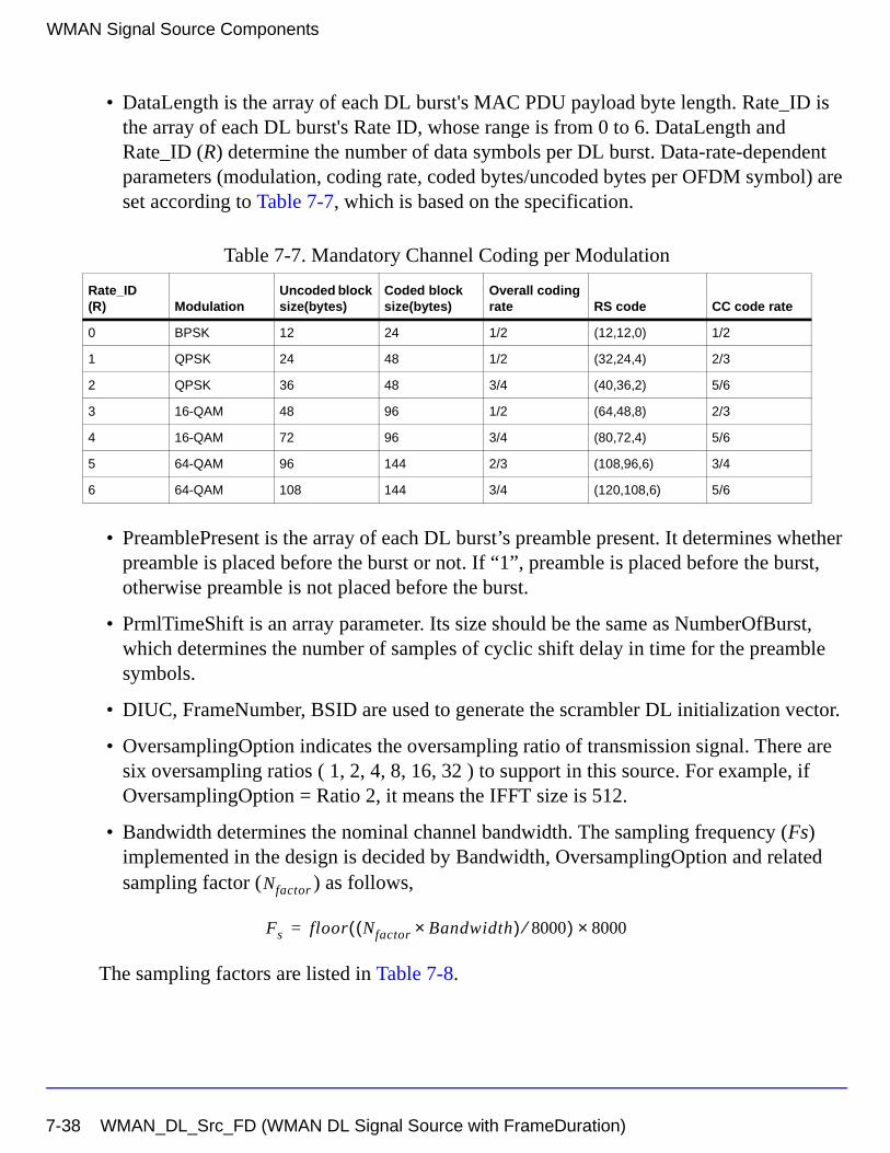
WMAN Signal Source Components
• DataLength is the array of each DL burst's MAC PDU payload byte length. Rate_ID is the array of each DL burst's Rate ID, whose range is from 0 to 6. DataLength and Rate_ID (R) determine the number of data symbols per DL burst. Data-rate-dependent parameters (modulation, coding rate, coded bytes/uncoded bytes per OFDM symbol) are set according to Table 7-7, which is based on the specification.
• PreamblePresent is the array of each DL burst’s preamble present. It determines whether preamble is placed before the burst or not. If “1”, preamble is placed before the burst, otherwise preamble is not placed before the burst.
• PrmlTimeShift is an array parameter. Its size should be the same as NumberOfBurst, which determines the number of samples of cyclic shift delay in time for the preamble symbols.
• DIUC, FrameNumber, BSID are used to generate the scrambler DL initialization vector.
• OversamplingOption indicates the oversampling ratio of transmission signal. There are six oversampling ratios ( 1, 2, 4, 8, 16, 32 ) to support in this source. For example, if OversamplingOption = Ratio 2, it means the IFFT size is 512.
• Bandwidth determines the nominal channel bandwidth. The sampling frequency (Fs) implemented in the design is decided by Bandwidth, OversamplingOption and related sampling factor ( ) as follows,
The sampling factors are listed in Table 7-8.
Table 7-7. Mandatory Channel Coding per Modulation
Rate_ID(R) Modulation
Uncoded block size(bytes)
Coded block size(bytes)
Overall coding rate RS code CC code rate
0 BPSK 12 24 1/2 (12,12,0) 1/2
1 QPSK 24 48 1/2 (32,24,4) 2/3
2 QPSK 36 48 3/4 (40,36,2) 5/6
3 16-QAM 48 96 1/2 (64,48,8) 2/3
4 16-QAM 72 96 3/4 (80,72,4) 5/6
5 64-QAM 96 144 2/3 (108,96,6) 3/4
6 64-QAM 108 144 3/4 (120,108,6) 5/6
Nfactor
Fs floor Nfactor Bandwidth×( ) 8000⁄( ) 8000×=
7-38 WMAN_DL_Src_FD (WMAN DL Signal Source with FrameDuration)
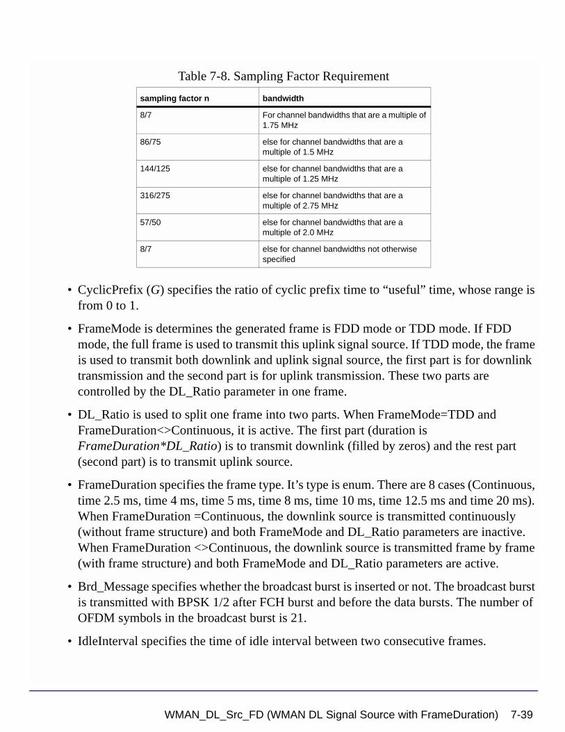
• CyclicPrefix (G) specifies the ratio of cyclic prefix time to “useful” time, whose range is from 0 to 1.
• FrameMode is determines the generated frame is FDD mode or TDD mode. If FDD mode, the full frame is used to transmit this uplink signal source. If TDD mode, the frame is used to transmit both downlink and uplink signal source, the first part is for downlink transmission and the second part is for uplink transmission. These two parts are controlled by the DL_Ratio parameter in one frame.
• DL_Ratio is used to split one frame into two parts. When FrameMode=TDD and FrameDuration<>Continuous, it is active. The first part (duration is FrameDuration*DL_Ratio) is to transmit downlink (filled by zeros) and the rest part (second part) is to transmit uplink source.
• FrameDuration specifies the frame type. It’s type is enum. There are 8 cases (Continuous, time 2.5 ms, time 4 ms, time 5 ms, time 8 ms, time 10 ms, time 12.5 ms and time 20 ms). When FrameDuration =Continuous, the downlink source is transmitted continuously (without frame structure) and both FrameMode and DL_Ratio parameters are inactive. When FrameDuration <>Continuous, the downlink source is transmitted frame by frame (with frame structure) and both FrameMode and DL_Ratio parameters are active.
• Brd_Message specifies whether the broadcast burst is inserted or not. The broadcast burst is transmitted with BPSK 1/2 after FCH burst and before the data bursts. The number of OFDM symbols in the broadcast burst is 21.
• IdleInterval specifies the time of idle interval between two consecutive frames.
Table 7-8. Sampling Factor Requirement
sampling factor n bandwidth
8/7 For channel bandwidths that are a multiple of 1.75 MHz
86/75 else for channel bandwidths that are a multiple of 1.5 MHz
144/125 else for channel bandwidths that are a multiple of 1.25 MHz
316/275 else for channel bandwidths that are a multiple of 2.75 MHz
57/50 else for channel bandwidths that are a multiple of 2.0 MHz
8/7 else for channel bandwidths not otherwise specified
WMAN_DL_Src_FD (WMAN DL Signal Source with FrameDuration) 7-39
WMAN Signal Source Components
• PilotPN_Phase specifies the start phase of pilots (PRBS). The specification requires PilotPN_Phase = 0.
• AutoMACHeaderSetting specifies whether the MAC_Header is generated automatically or not.
• MAC_Header specifies the MAC header of FEC-encoded burst. This parameter is only active when AutoMACHeaderSetting is set to NO.
• UL_ChannelID specifies the uplink channel ID. This parameter is used in UL-MAP.
• UCD_Count specifies the UCD count. This parameter is used in UCD.
• UL_NumberOfSS specifies the number of the uplink subscribers. This parameter is used in UL-MAP.
• UL_CID specifies the CID for the uplink subscribers. This parameter is used in UL-MAP.
• UL_DataLength specifies the data length for the uplink subscribers. This parameter is used in UL-MAP.
• UL_Rate_ID specifies the rate ID for the uplink subscribers. This parameter is used in UL-MAP.
• UL_Subchannelization specifies whether subchannelization is used or not. This parameter is used in UL-MAP.
• UL_SubchannelIndex specifies the index of subchannels for the uplink subscribers. This parameter is used in UL-MAP.
• UL_MidambleRepetition specifies the repetition of midambles for the uplink subscribers. This parameter is used in UL-MAP.
5. Samples per frame
One WMAN downlink frame consists of Idle, long preamble, FCH, broadcast burst and multiple downlink bursts.
The downlink long preamble consists of two consecutive OFDM symbols.
FCH is transmitted in one OFDM symbol. The number of OFDM symbols of the ith downlink burst( ) is calculated as follows:NSymbol i[ ]
NSymbol i[ ] ceil DataLength i[ ] 11+( ) uncodedBlockSize R i[ ][ ]( )⁄( )=
7-40 WMAN_DL_Src_FD (WMAN DL Signal Source with FrameDuration)
PreamblePresent indicates whether the downlink burst starts with a short preamble or not.
Let represent the number of OFDM symbol per each preamble present. If
preamblePresent is set to 1 in the ith burst, then , otherwise, .
So the total number of OFDM symbols for the downlink frame is calculated
as follows:
is the number of OFDM symbols of the broadcast burst where it is equal to 21 when
Brd_Message is YES and is equal to 0 when Brd_Message is NO.
The number of samples per one OFDM symbol ( ) is calculated as:
The samples of IdleInterval( ) is calculated as follows:
If FrameDuration is Continuous, the total samples of one downlink frame
is
Otherwise, if FrameDuration is set to other values (2.5 ms, 4 ms, 5 ms, 8 ms, 10 ms, 12.5 ms
or 20 ms), the total samples of one downlink frame is
This model work on frame by frame. Each firing, tokens are consumed
at pin MAC_PDU, tokens are produced at pin FrameData,
tokens are produced at pin ForEVM,
Prml i[ ]
Prml i[ ] 1= Prml i[ ] 0=
NtotalSymbol
NtotalSymbol 2 1 NBrdcst NSymbol i[ ] Prml i[ ]+( )i 1=
NumberOfBurst
∑+ + +=
NBrdcst
SamplesOFDM
SamplesOFDM 2OversamplingOption
256× 1 G+( )×=
Samplesidle
Samplesidle IdleInterval 2OversamplingOption
Fs××=
SamplesFrame
SamplesFrame Samplesidle NtotalSymbol SamplesOFDM×+=
SamplesFrame
SamplesFrame Samplesidle FrameDuration Fs 2× OversamplingOption×+=
8 DataLength×
SamplesFrame
200 1 NBrdcst NSymbol i[ ]i 1=
NumberOfBurst
∑+ +
×
WMAN_DL_Src_FD (WMAN DL Signal Source with FrameDuration) 7-41
WMAN Signal Source Components
tokens are produced at pin PSDUFCS, and 11 tokens are produced at
pin DLFP.
6. Output delay
delay is introduced by TransmitterFilter in the design WMAN_DL_SignalSrc, where the delay are equal to . Length is the parameter in TransmitterFilter.
References
[1] IEEE Std 802.16-2004, Part 16: Air Interface for Fixed Broadband Wireless Access Systems, Section 8.3 WirelessMAN-OFDM PHY, October 1, 2004.
[2] IEEE P802.16-2004/Cor1/D5, Corrigendum to IEEE Standard for Local and Metropolitan Area Networks - Part 16: Air Interface for Fixed Broadband Wireless Access Systems, Sept. 2005.
8 DataLength× 80+
30 2oversamplingOption×
Length 1–( ) 2⁄
7-42 WMAN_DL_Src_FD (WMAN DL Signal Source with FrameDuration)
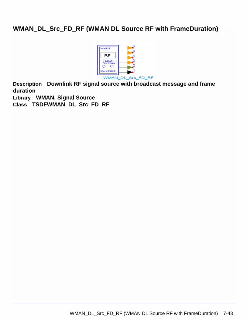
WMAN_DL_Src_FD_RF (WMAN DL Source RF with FrameDuration)
Description Downlink RF signal source with broadcast message and frame durationLibrary WMAN, Signal SourceClass TSDFWMAN_DL_Src_FD_RF
WMAN_DL_Src_FD_RF (WMAN DL Source RF with FrameDuration) 7-43
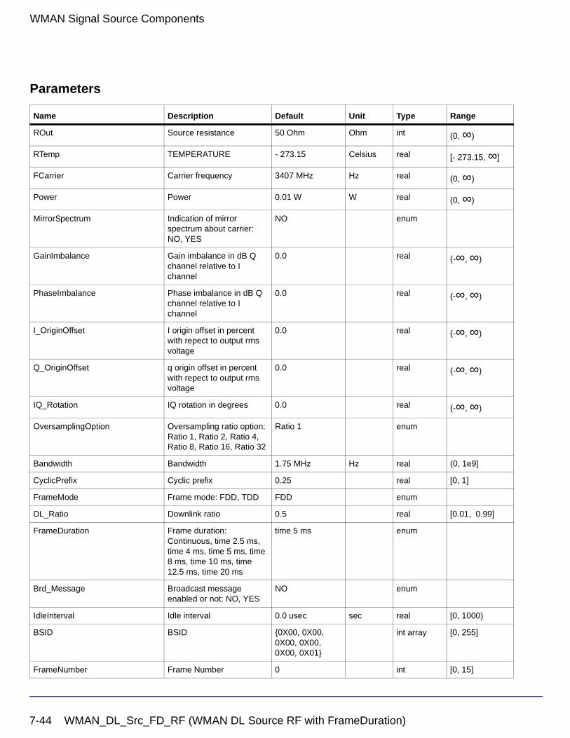
WMAN Signal Source Components
Parameters
Name Description Default Unit Type Range
ROut Source resistance 50 Ohm Ohm int (0, ∞)
RTemp TEMPERATURE - 273.15 Celsius real [- 273.15, ∞]
FCarrier Carrier frequency 3407 MHz Hz real (0, ∞)
Power Power 0.01 W W real (0, ∞)
MirrorSpectrum Indication of mirror spectrum about carrier: NO, YES
NO enum
GainImbalance Gain imbalance in dB Q channel relative to I channel
0.0 real (-∞, ∞)
PhaseImbalance Phase imbalance in dB Q channel relative to I channel
0.0 real (-∞, ∞)
I_OriginOffset I origin offset in percent with repect to output rms voltage
0.0 real (-∞, ∞)
Q_OriginOffset q origin offset in percent with repect to output rms voltage
0.0 real (-∞, ∞)
IQ_Rotation IQ rotation in degrees 0.0 real (-∞, ∞)
OversamplingOption Oversampling ratio option: Ratio 1, Ratio 2, Ratio 4, Ratio 8, Ratio 16, Ratio 32
Ratio 1 enum
Bandwidth Bandwidth 1.75 MHz Hz real (0, 1e9]
CyclicPrefix Cyclic prefix 0.25 real [0, 1]
FrameMode Frame mode: FDD, TDD FDD enum
DL_Ratio Downlink ratio 0.5 real [0.01, 0.99]
FrameDuration Frame duration: Continuous, time 2.5 ms, time 4 ms, time 5 ms, time 8 ms, time 10 ms, time 12.5 ms, time 20 ms
time 5 ms enum
Brd_Message Broadcast message enabled or not: NO, YES
NO enum
IdleInterval Idle interval 0.0 usec sec real [0, 1000)
BSID BSID {0X00, 0X00, 0X00, 0X00, 0X00, 0X01}
int array [0, 255]
FrameNumber Frame Number 0 int [0, 15]
7-44 WMAN_DL_Src_FD_RF (WMAN DL Source RF with FrameDuration)
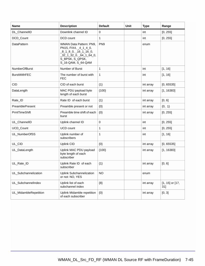
DL_ChannelID Downlink channel ID 0 int [0, 255]
DCD_Count DCD count 1 int [0, 255]
DataPattern WMAN Data Pattern: PN9, PN15, FIX4, _4_1_4_0, _8_1_8_0, _16_1_16_0, _32_1_32_0, _64_1_64_0, S_BPSK, S_QPSK, S_16-QAM, S_64-QAM
PN9 enum
NumberOfBurst Number of Burst 1 int [1, 16]
BurstWithFEC The number of burst with FEC
1 int [1, 16]
CID CID of each burst {1} int array [0, 65535]
DataLength MAC PDU payload byte length of each burst
{100} int array [1, 16383]
Rate_ID Rate ID of each burst {1} int array [0, 6]
PreamblePresent Preamble present or not {0} int array {0, 1}
PrmlTimeShift Preamble time shift of each burst
{0} int array [0, 255]
UL_ChannelID Uplink channel ID 0 int [0, 255]
UCD_Count UCD count 1 int [0, 255]
UL_NumberOfSS Uplink number of subscribers
1 int [1, 16]
UL_CID Uplink CID {0} int array [0, 65535]
UL_DataLength Uplink MAC PDU payload byte length of each subscriber
{100} int array [1, 16383]
UL_Rate_ID Uplink Rate ID of each subscriber
{1} int array [0, 6]
UL_Subchannelization Uplink Subchannelization or not: NO, YES
NO enum
UL_SubchannelIndex Uplink list of each subchannel index
{8} int array [1, 15] or [17, 31]
UL_MidambleRepetition Uplink Midamble repetition of each subscriber
{0} int array [0, 3]
Name Description Default Unit Type Range
WMAN_DL_Src_FD_RF (WMAN DL Source RF with FrameDuration) 7-45
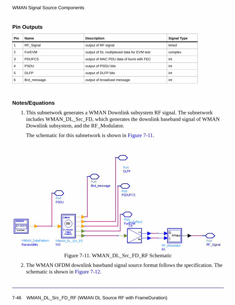
WMAN Signal Source Components
Pin Outputs
Notes/Equations
1. This subnetwork generates a WMAN Downlink subsystem RF signal. The subnetwork includes WMAN_DL_Src_FD, which generates the downlink baseband signal of WMAN Downlink subsystem, and the RF_Modulator.
The schematic for this subnetwork is shown in Figure 7-11.
Figure 7-11. WMAN_DL_Src_FD_RF Schematic
2. The WMAN OFDM downlink baseband signal source format follows the specification. The schematic is shown in Figure 7-12.
Pin Name Description Signal Type
1 RF_Signal output of RF signal timed
2 ForEVM output of DL multiplexed data for EVM test complex
3 PDUFCS output of MAC PDU data of burst with FEC int
4 PSDU output of PSDU bits int
5 DLFP output of DLFP bits int
6 Brd_message output of broadcast message int
7-46 WMAN_DL_Src_FD_RF (WMAN DL Source RF with FrameDuration)
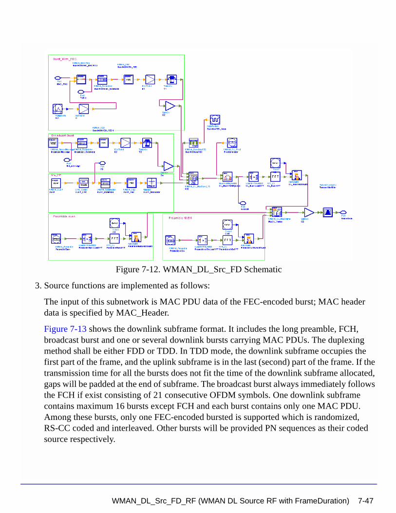
Figure 7-12. WMAN_DL_Src_FD Schematic
3. Source functions are implemented as follows:
The input of this subnetwork is MAC PDU data of the FEC-encoded burst; MAC header data is specified by MAC_Header.
Figure 7-13 shows the downlink subframe format. It includes the long preamble, FCH, broadcast burst and one or several downlink bursts carrying MAC PDUs. The duplexing method shall be either FDD or TDD. In TDD mode, the downlink subframe occupies the first part of the frame, and the uplink subframe is in the last (second) part of the frame. If the transmission time for all the bursts does not fit the time of the downlink subframe allocated, gaps will be padded at the end of subframe. The broadcast burst always immediately follows the FCH if exist consisting of 21 consecutive OFDM symbols. One downlink subframe contains maximum 16 bursts except FCH and each burst contains only one MAC PDU. Among these bursts, only one FEC-encoded bursted is supported which is randomized, RS-CC coded and interleaved. Other bursts will be provided PN sequences as their coded source respectively.
WMAN_DL_Src_FD_RF (WMAN DL Source RF with FrameDuration) 7-47
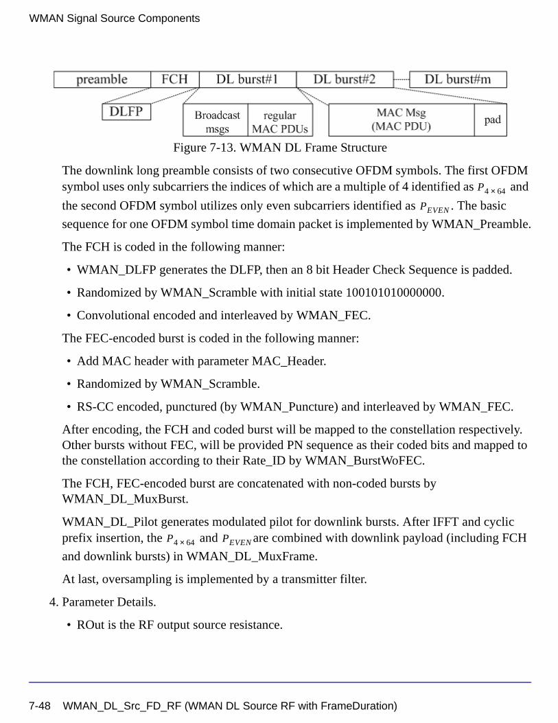
WMAN Signal Source Components
Figure 7-13. WMAN DL Frame Structure
The downlink long preamble consists of two consecutive OFDM symbols. The first OFDM symbol uses only subcarriers the indices of which are a multiple of 4 identified as and
the second OFDM symbol utilizes only even subcarriers identified as . The basic
sequence for one OFDM symbol time domain packet is implemented by WMAN_Preamble.
The FCH is coded in the following manner:
• WMAN_DLFP generates the DLFP, then an 8 bit Header Check Sequence is padded.
• Randomized by WMAN_Scramble with initial state 100101010000000.
• Convolutional encoded and interleaved by WMAN_FEC.
The FEC-encoded burst is coded in the following manner:
• Add MAC header with parameter MAC_Header.
• Randomized by WMAN_Scramble.
• RS-CC encoded, punctured (by WMAN_Puncture) and interleaved by WMAN_FEC.
After encoding, the FCH and coded burst will be mapped to the constellation respectively. Other bursts without FEC, will be provided PN sequence as their coded bits and mapped to the constellation according to their Rate_ID by WMAN_BurstWoFEC.
The FCH, FEC-encoded burst are concatenated with non-coded bursts by WMAN_DL_MuxBurst.
WMAN_DL_Pilot generates modulated pilot for downlink bursts. After IFFT and cyclic prefix insertion, the and are combined with downlink payload (including FCH
and downlink bursts) in WMAN_DL_MuxFrame.
At last, oversampling is implemented by a transmitter filter.
4. Parameter Details.
• ROut is the RF output source resistance.
P4 64×
PEVEN
P4 64× PEVEN
7-48 WMAN_DL_Src_FD_RF (WMAN DL Source RF with FrameDuration)
• RTemp is the RF output source resistance temperature in Celsius and sets the noise density in the RF output signal to (k(RTemp+273.15)) Watts/Hz, where k is Boltzmann's constant.
• FCarrier is the RF output signal frequency.
• Power is used to set the modulator output RF power. This is true for an ideal transmitted signal (no impairments added) or when small impairments are added. If large impairments are added to the signal (using GainImbalance, I_OriginOffset, and Q_OriginOffset parameters) the output RF power may be different from the value of the Power parameter.
• MirrorSpectrum is used to mirror the RF_out signal spectrum about the carrier. This is equivalent to conjugating the complex RF envelope voltage. Depending on the configuration and number of mixers in an RF transmitter, the RF output signal from hardware RF generators can be inverted. If such an RF signal is desired, set this parameter to YES.
• GainImbalance, PhaseImbalance, I_OriginOffset, Q_OriginOffset, and IQ_Rotation are used to add certain impairments to the ideal output RF signal. Impairments are added in the order described here.
The unimpaired RF I and Q envelope voltages have gain and phase imbalance applied. The RF is given by:
where A is a scaling factor based on the Power and ROut parameters specified by the user, VI(t) is the in-phase RF envelope, VQ(t) is the quadrature phase RF envelope, g is
the gain imbalance
and, (in degrees) is the phase imbalance.
Next, the signal VRF(t) is rotated by IQ_Rotation degrees. The I_OriginOffset and
Q_OriginOffset are then applied to the rotated signal. Note that the amounts specified are percentages with respect to the output rms voltage. The output rms voltage is given by sqrt(2×ROut×Power).
• NumberOfBurst specifies the number of active downlink bursts.
• BurstWithFEC specifies the downlink burst FEC.
VRF t( ) A VI t( ) ωct( )cos gVQ t( ) ωctΦπ180---------+
sin– =
g 10
GainImbalance20
-----------------------------------------
=
φ
WMAN_DL_Src_FD_RF (WMAN DL Source RF with FrameDuration) 7-49
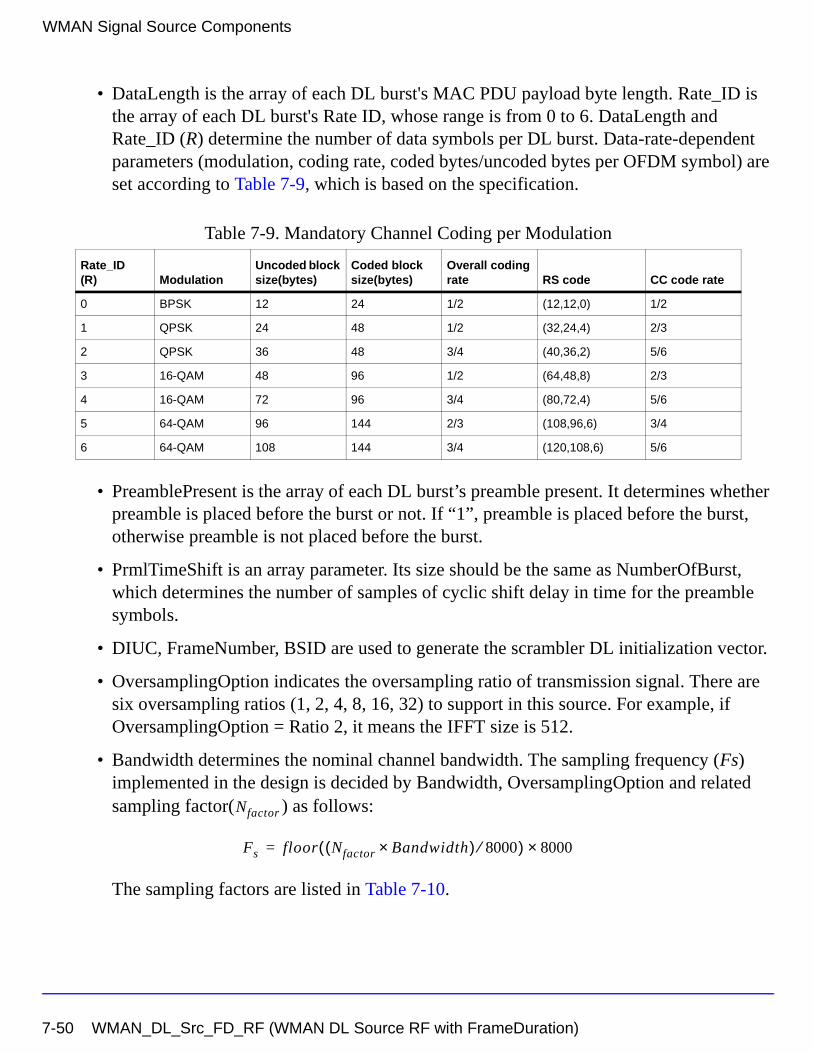
WMAN Signal Source Components
• DataLength is the array of each DL burst's MAC PDU payload byte length. Rate_ID is the array of each DL burst's Rate ID, whose range is from 0 to 6. DataLength and Rate_ID (R) determine the number of data symbols per DL burst. Data-rate-dependent parameters (modulation, coding rate, coded bytes/uncoded bytes per OFDM symbol) are set according to Table 7-9, which is based on the specification.
• PreamblePresent is the array of each DL burst’s preamble present. It determines whether preamble is placed before the burst or not. If “1”, preamble is placed before the burst, otherwise preamble is not placed before the burst.
• PrmlTimeShift is an array parameter. Its size should be the same as NumberOfBurst, which determines the number of samples of cyclic shift delay in time for the preamble symbols.
• DIUC, FrameNumber, BSID are used to generate the scrambler DL initialization vector.
• OversamplingOption indicates the oversampling ratio of transmission signal. There are six oversampling ratios (1, 2, 4, 8, 16, 32) to support in this source. For example, if OversamplingOption = Ratio 2, it means the IFFT size is 512.
• Bandwidth determines the nominal channel bandwidth. The sampling frequency (Fs) implemented in the design is decided by Bandwidth, OversamplingOption and related sampling factor( ) as follows:
The sampling factors are listed in Table 7-10.
Table 7-9. Mandatory Channel Coding per Modulation
Rate_ID(R) Modulation
Uncoded block size(bytes)
Coded block size(bytes)
Overall coding rate RS code CC code rate
0 BPSK 12 24 1/2 (12,12,0) 1/2
1 QPSK 24 48 1/2 (32,24,4) 2/3
2 QPSK 36 48 3/4 (40,36,2) 5/6
3 16-QAM 48 96 1/2 (64,48,8) 2/3
4 16-QAM 72 96 3/4 (80,72,4) 5/6
5 64-QAM 96 144 2/3 (108,96,6) 3/4
6 64-QAM 108 144 3/4 (120,108,6) 5/6
Nfactor
Fs floor Nfactor Bandwidth×( ) 8000⁄( ) 8000×=
7-50 WMAN_DL_Src_FD_RF (WMAN DL Source RF with FrameDuration)
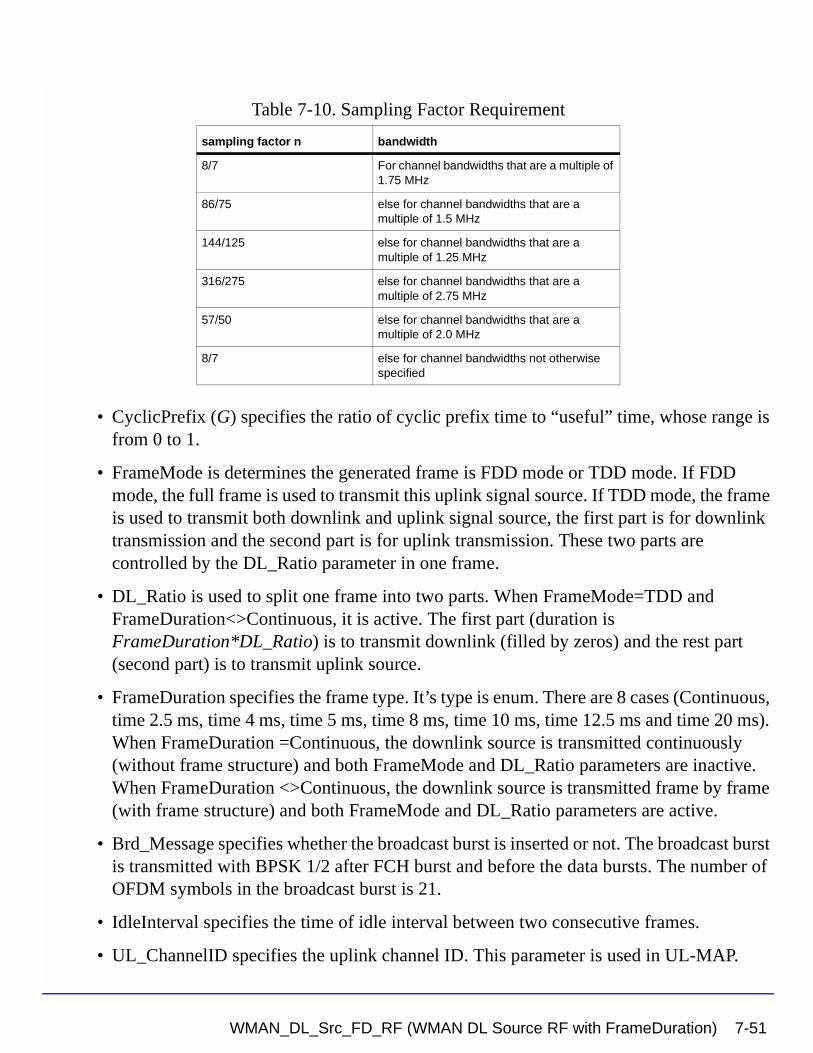
• CyclicPrefix (G) specifies the ratio of cyclic prefix time to “useful” time, whose range is from 0 to 1.
• FrameMode is determines the generated frame is FDD mode or TDD mode. If FDD mode, the full frame is used to transmit this uplink signal source. If TDD mode, the frame is used to transmit both downlink and uplink signal source, the first part is for downlink transmission and the second part is for uplink transmission. These two parts are controlled by the DL_Ratio parameter in one frame.
• DL_Ratio is used to split one frame into two parts. When FrameMode=TDD and FrameDuration<>Continuous, it is active. The first part (duration is FrameDuration*DL_Ratio) is to transmit downlink (filled by zeros) and the rest part (second part) is to transmit uplink source.
• FrameDuration specifies the frame type. It’s type is enum. There are 8 cases (Continuous, time 2.5 ms, time 4 ms, time 5 ms, time 8 ms, time 10 ms, time 12.5 ms and time 20 ms). When FrameDuration =Continuous, the downlink source is transmitted continuously (without frame structure) and both FrameMode and DL_Ratio parameters are inactive. When FrameDuration <>Continuous, the downlink source is transmitted frame by frame (with frame structure) and both FrameMode and DL_Ratio parameters are active.
• Brd_Message specifies whether the broadcast burst is inserted or not. The broadcast burst is transmitted with BPSK 1/2 after FCH burst and before the data bursts. The number of OFDM symbols in the broadcast burst is 21.
• IdleInterval specifies the time of idle interval between two consecutive frames.
• UL_ChannelID specifies the uplink channel ID. This parameter is used in UL-MAP.
Table 7-10. Sampling Factor Requirement
sampling factor n bandwidth
8/7 For channel bandwidths that are a multiple of 1.75 MHz
86/75 else for channel bandwidths that are a multiple of 1.5 MHz
144/125 else for channel bandwidths that are a multiple of 1.25 MHz
316/275 else for channel bandwidths that are a multiple of 2.75 MHz
57/50 else for channel bandwidths that are a multiple of 2.0 MHz
8/7 else for channel bandwidths not otherwise specified
WMAN_DL_Src_FD_RF (WMAN DL Source RF with FrameDuration) 7-51
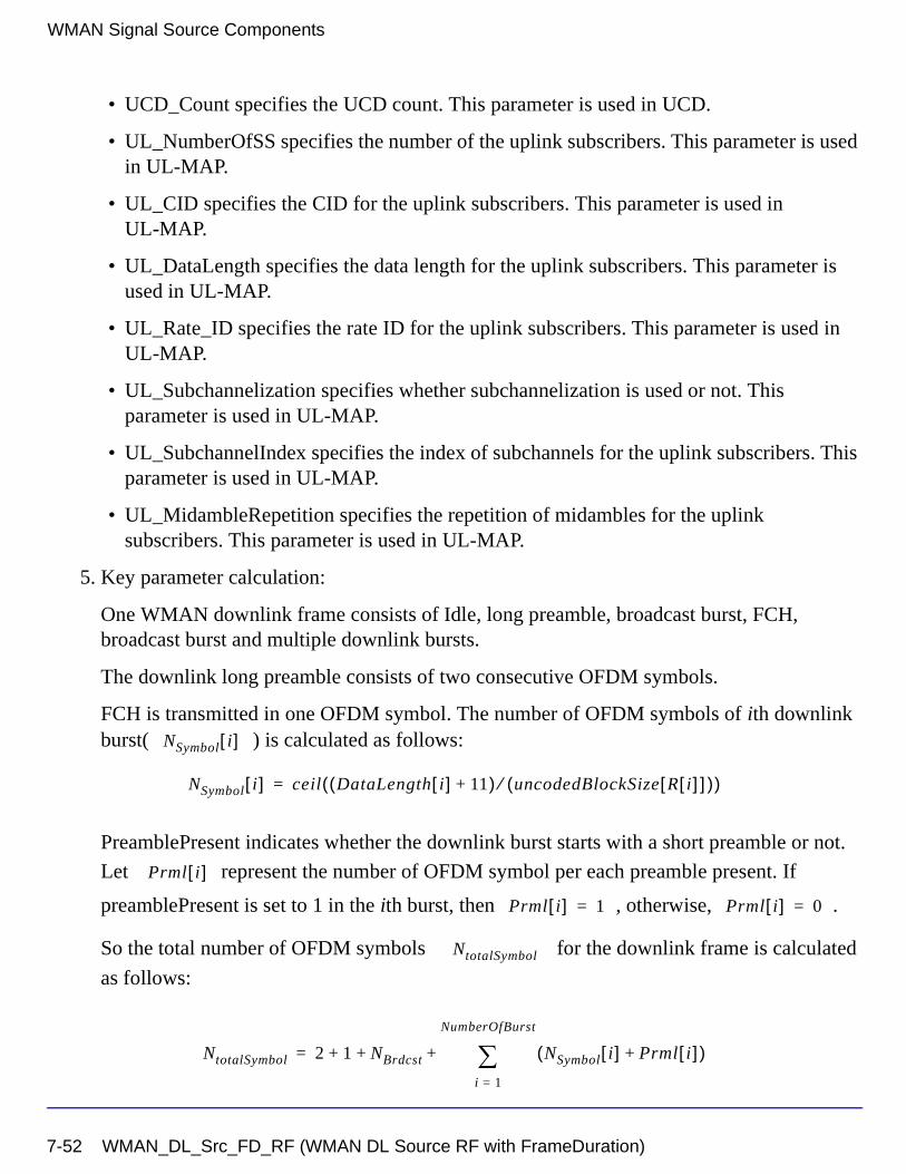
WMAN Signal Source Components
• UCD_Count specifies the UCD count. This parameter is used in UCD.
• UL_NumberOfSS specifies the number of the uplink subscribers. This parameter is used in UL-MAP.
• UL_CID specifies the CID for the uplink subscribers. This parameter is used in UL-MAP.
• UL_DataLength specifies the data length for the uplink subscribers. This parameter is used in UL-MAP.
• UL_Rate_ID specifies the rate ID for the uplink subscribers. This parameter is used in UL-MAP.
• UL_Subchannelization specifies whether subchannelization is used or not. This parameter is used in UL-MAP.
• UL_SubchannelIndex specifies the index of subchannels for the uplink subscribers. This parameter is used in UL-MAP.
• UL_MidambleRepetition specifies the repetition of midambles for the uplink subscribers. This parameter is used in UL-MAP.
5. Key parameter calculation:
One WMAN downlink frame consists of Idle, long preamble, broadcast burst, FCH, broadcast burst and multiple downlink bursts.
The downlink long preamble consists of two consecutive OFDM symbols.
FCH is transmitted in one OFDM symbol. The number of OFDM symbols of ith downlink burst( ) is calculated as follows:
PreamblePresent indicates whether the downlink burst starts with a short preamble or not.
Let represent the number of OFDM symbol per each preamble present. If
preamblePresent is set to 1 in the ith burst, then , otherwise, .
So the total number of OFDM symbols for the downlink frame is calculated
as follows:
NSymbol i[ ]
NSymbol i[ ] ceil DataLength i[ ] 11+( ) uncodedBlockSize R i[ ][ ]( )⁄( )=
Prml i[ ]
Prml i[ ] 1= Prml i[ ] 0=
NtotalSymbol
NtotalSymbol 2 1 NBrdcst NSymbol i[ ] Prml i[ ]+( )i 1=
NumberOfBurst
∑+ + +=
7-52 WMAN_DL_Src_FD_RF (WMAN DL Source RF with FrameDuration)
is the number of OFDM symbols of the broadcast burst where it is equal to 21 when
Brd_Message is YES and is equal to 0 when Brd_Message is NO.
The number of samples per one OFDM symbol ( ) is calculated as:
The samples of IdleInterval( ) is calculated as follows:
If FrameDuration is Continuous, the total samples of one downlink frame
is
Otherwise, if FrameDuration is set to other values (2.5 ms, 4 ms, 5 ms, 8 ms, 10 ms, 12.5 ms
or 20 ms), the total samples of one downlink frame is
6. Output delay
delay is introduced by TransmitterFilter in the design WMAN_DL_SignalSrc, where the delay are equal to . Length is the parameter in TransmitterFilter.
References
[1] IEEE Std 802.16-2004, Part 16: Air Interface for Fixed Broadband Wireless Access Systems, Section 8.3 WirelessMAN-OFDM PHY, October 1, 2004.
[2] IEEE P802.16-2004/Cor1/D5, Corrigendum to IEEE Standard for Local and Metropolitan Area Networks - Part 16: Air Interface for Fixed Broadband Wireless Access Systems, Sept. 2005.
NBrdcst
SamplesOFDM
SamplesOFDM 2OversamplingOption
256× 1 G+( )×=
Samplesidle
Samplesidle IdleInterval 2OversamplingOption
Fs××=
SamplesFrame
SamplesFrame Samplesidle NtotalSymbol SamplesOFDM×+=
SamplesFrame
SamplesFrame Samplesidle FrameDuration Fs 2× OversamplingOption×+=
30 2oversamplingOption×
Length 1–( ) 2⁄
WMAN_DL_Src_FD_RF (WMAN DL Source RF with FrameDuration) 7-53
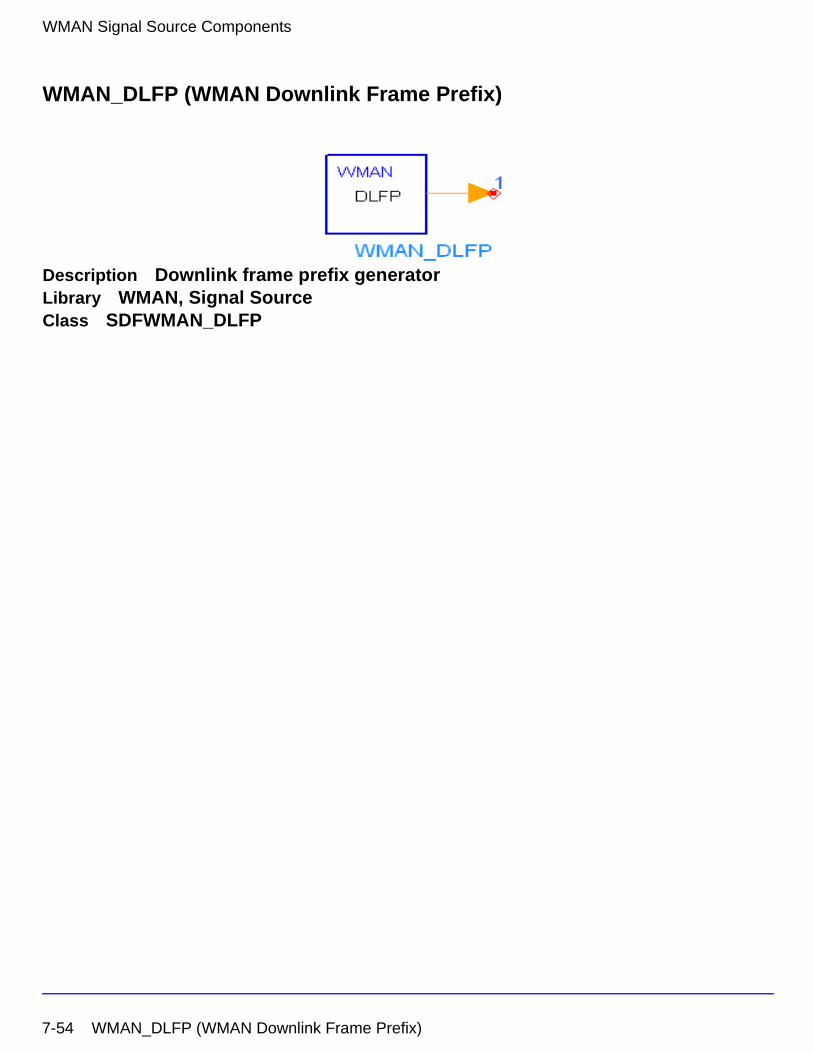
WMAN Signal Source Components
WMAN_DLFP (WMAN Downlink Frame Prefix)
Description Downlink frame prefix generatorLibrary WMAN, Signal SourceClass SDFWMAN_DLFP
7-54 WMAN_DLFP (WMAN Downlink Frame Prefix)
Parameters
Pin Outputs
Notes/Equations
1. This model is used to generate Downlink Frame Prefix (DLFP). The FCH contains DLFP to specify burst profile and length of one or several downlink bursts immediately following the FCH.
2. Each firing 10×8 bit tokens are produced at Pin out. The content in DLFP is specified in Table 7-11.
Name Description Default Type Range
BSID Base station identifier 0 int [0, 15]
DIUC Downlink interval usage code
{0} int array [0, 15]
FrameNumber Frame index 0 int [0, 15]
NumOfBurst Number of burst 1 int [1, 16]
Rate_ID Rate identifier {1} int array [0, 6]
DataLength MAC PDU payload byte length of each burst
{100} int array [1, 16383]
PreamblePresent Preamble present indication
{0} int array { 0, 1 }
Brd_Message Broadcast message or not: NO, YES
NO enum
Rate_ID_Brd Rate ID of broadcast message
0 int [0, 6]
DIUC_Brd Downlink interval usage code for broadcast message
0 int [0, 15]
Pin Name Description Signal Type
1 out downlink frame prefix int
WMAN_DLFP (WMAN Downlink Frame Prefix) 7-55
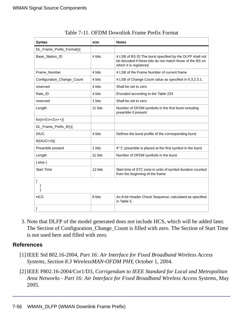
WMAN Signal Source Components
3. Note that DLFP of the model generated does not include HCS, which will be added later. The Section of Configuration_Change_Count is filled with zero. The Section of Start Time is not used here and filled with zero.
References
[1] IEEE Std 802.16-2004, Part 16: Air Interface for Fixed Broadband Wireless Access Systems, Section 8.3 WirelessMAN-OFDM PHY, October 1, 2004.
[2] IEEE P802.16-2004/Cor1/D3, Corrigendum to IEEE Standard for Local and Metropolitan Area Networks - Part 16: Air Interface for Fixed Broadband Wireless Access Systems, May 2005.
Table 7-11. OFDM Downlink Frame Prefix Format
Syntax size Notes
DL_Frame_Prefix_Format(){
Base_Station_ID 4 bits 4 LSB of BS ID.The burst specified by the DLFP shall not be decoded if these bits do not match those of the BS on which it is registered.
Frame_Number 4 bits 4 LSB of the Frame Number of current frame
Configuration_Change_Count 4 bits 4 LSB of Change Count value as specified in 6.3.2.3.1.
reserved 4 bits Shall be set to zero
Rate_ID 4 bits Encoded according to the Table 224
reserved 1 bits Shall be set to zero
Length 11 bits Number of OFDM symbols in the first burst including preamble if present
for(n=0;n<3;n++){
DL_Frame_Prefix_IE(){
DIUC 4 bits Defines the burst profile of the corresponding burst
if(DIUC!=0){
Preamble present 1 bits If “1”,preamble is placed at the first symbol in the burst
Length 11 bits Number of OFDM symbols in the burst
} else {
Start Time 12 bits Start time of STC zone in units of symbol duration counted from the beginning of the frame
}}}
HCS 8 bits An 8-bit Header Check Sequence; calculated as specified in Table 5.
}
7-56 WMAN_DLFP (WMAN Downlink Frame Prefix)
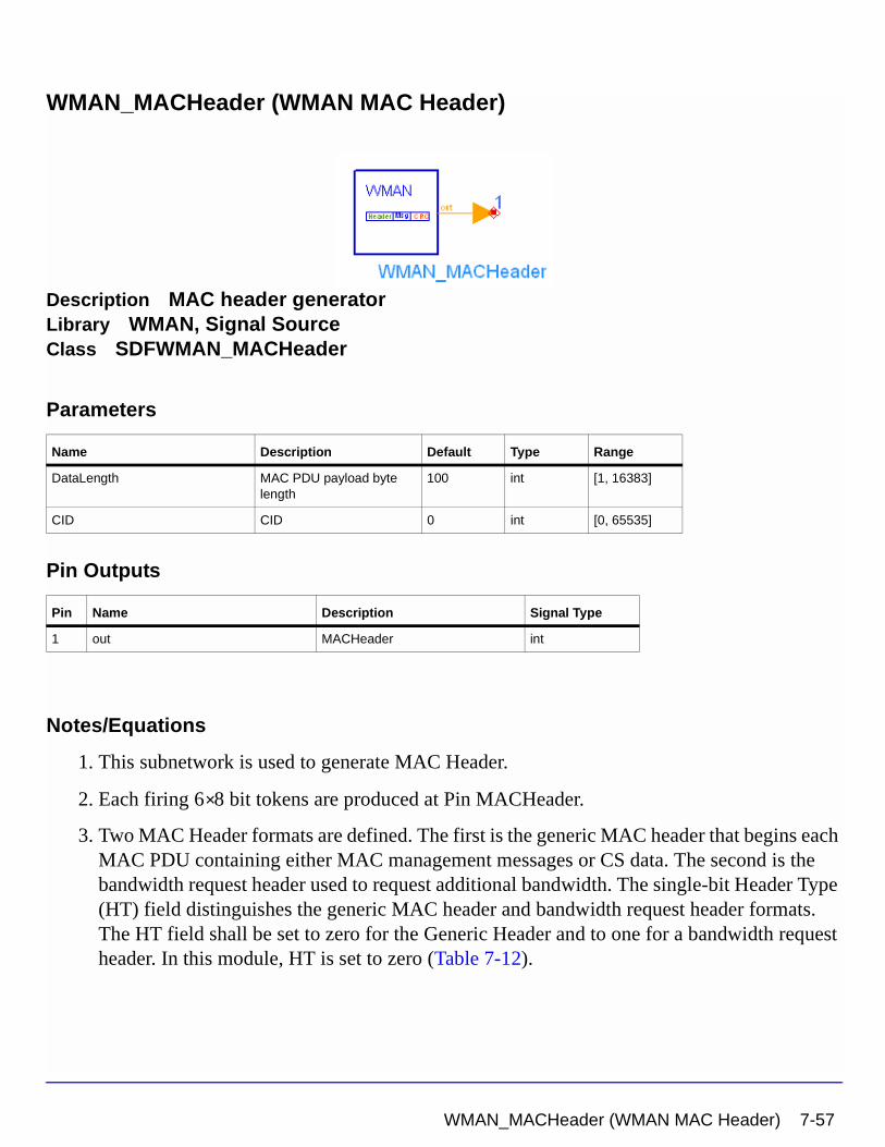
WMAN_MACHeader (WMAN MAC Header)
Description MAC header generatorLibrary WMAN, Signal SourceClass SDFWMAN_MACHeader
Parameters
Pin Outputs
Notes/Equations
1. This subnetwork is used to generate MAC Header.
2. Each firing 6 8 bit tokens are produced at Pin MACHeader.
3. Two MAC Header formats are defined. The first is the generic MAC header that begins each MAC PDU containing either MAC management messages or CS data. The second is the bandwidth request header used to request additional bandwidth. The single-bit Header Type (HT) field distinguishes the generic MAC header and bandwidth request header formats. The HT field shall be set to zero for the Generic Header and to one for a bandwidth request header. In this module, HT is set to zero (Table 7-12).
Name Description Default Type Range
DataLength MAC PDU payload byte length
100 int [1, 16383]
CID CID 0 int [0, 65535]
Pin Name Description Signal Type
1 out MACHeader int
×
WMAN_MACHeader (WMAN MAC Header) 7-57
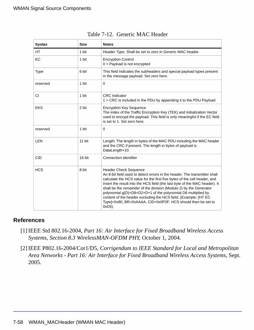
WMAN Signal Source Components
References
[1] IEEE Std 802.16-2004, Part 16: Air Interface for Fixed Broadband Wireless Access Systems, Section 8.3 WirelessMAN-OFDM PHY, October 1, 2004.
[2] IEEE P802.16-2004/Cor1/D5, Corrigendum to IEEE Standard for Local and Metropolitan Area Networks - Part 16: Air Interface for Fixed Broadband Wireless Access Systems, Sept. 2005.
Table 7-12. Generic MAC Header
Syntax Size Notes
HT 1 bit Header Type. Shall be set to zero in Generic MAC header.
EC 1 bit Encryption Control0 = Payload is not encrypted
Type 6 bit This field indicates the subheaders and special payload types present in the message payload. Set zero here.
reserved 1 bit 0
CI 1 bit CRC Indicator1 = CRC is included in the PDU by appending it to the PDU Payload
EKS 2 bit Encryption Key SequenceThe index of the Traffic Encryption Key (TEK) and Initialization Vector used to encrypt the payload. This field is only meaningful if the EC field is set to 1. Set zero here.
reserved 1 bit 0
LEN 11 bit Length. The length in bytes of the MAC PDU including the MAC header and the CRC if present. The length in bytes of payload is DataLength+10.
CID 16 bit Connection identifier
HCS 8 bit Header Check SequenceAn 8-bit field used to detect errors in the header. The transmitter shall calculate the HCS value for the first five bytes of the cell header, and insert the result into the HCS field (the last byte of the MAC header). It shall be the remainder of the division (Modulo 2) by the Generator polynomial g(D)=D8+D2+D+1 of the polynomial D8 multiplied by content of the header excluding the HCS field. (Example: [HT EC Type]=0x80, BR=0xAAAA, CID=0x0F0F; HCS should then be set to 0xD5).
7-58 WMAN_MACHeader (WMAN MAC Header)
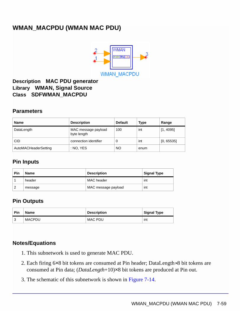
WMAN_MACPDU (WMAN MAC PDU)
Description MAC PDU generatorLibrary WMAN, Signal SourceClass SDFWMAN_MACPDU
Parameters
Pin Inputs
Pin Outputs
Notes/Equations
1. This subnetwork is used to generate MAC PDU.
2. Each firing 6×8 bit tokens are consumed at Pin header; DataLength 8 bit tokens are consumed at Pin data; (DataLength+10)×8 bit tokens are produced at Pin out.
3. The schematic of this subnetwork is shown in Figure 7-14.
Name Description Default Type Range
DataLength MAC message payload byte length
100 int [1, 4095]
CID connection identifier 0 int [0, 65535]
AutoMACHeaderSetting : NO, YES NO enum
Pin Name Description Signal Type
1 header MAC header int
2 message MAC message payload int
Pin Name Description Signal Type
3 MACPDU MAC PDU int
×
WMAN_MACPDU (WMAN MAC PDU) 7-59
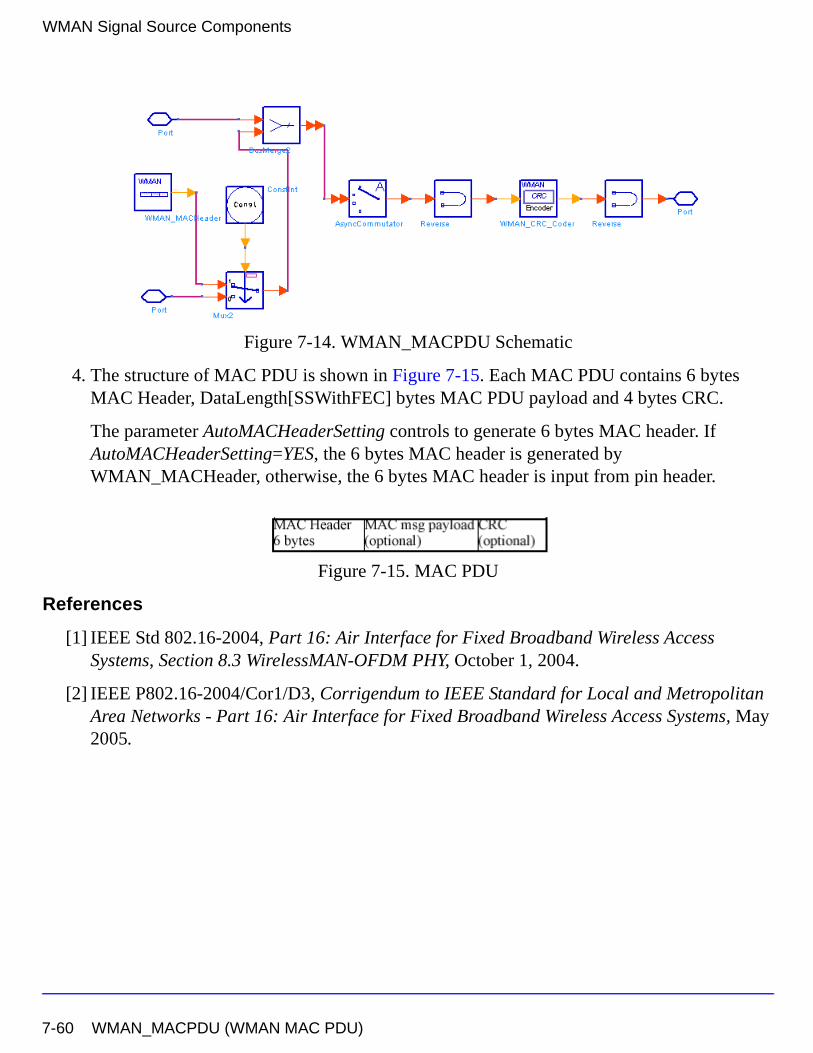
WMAN Signal Source Components
Figure 7-14. WMAN_MACPDU Schematic
4. The structure of MAC PDU is shown in Figure 7-15. Each MAC PDU contains 6 bytes MAC Header, DataLength[SSWithFEC] bytes MAC PDU payload and 4 bytes CRC.
The parameter AutoMACHeaderSetting controls to generate 6 bytes MAC header. If AutoMACHeaderSetting=YES, the 6 bytes MAC header is generated by WMAN_MACHeader, otherwise, the 6 bytes MAC header is input from pin header.
Figure 7-15. MAC PDU
References
[1] IEEE Std 802.16-2004, Part 16: Air Interface for Fixed Broadband Wireless Access Systems, Section 8.3 WirelessMAN-OFDM PHY, October 1, 2004.
[2] IEEE P802.16-2004/Cor1/D3, Corrigendum to IEEE Standard for Local and Metropolitan Area Networks - Part 16: Air Interface for Fixed Broadband Wireless Access Systems, May 2005.
7-60 WMAN_MACPDU (WMAN MAC PDU)
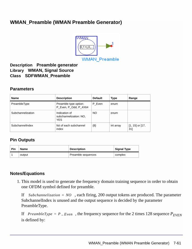
WMAN_Preamble (WMAN Preamble Generator)
Description Preamble generatorLibrary WMAN, Signal SourceClass SDFWMAN_Preamble
Parameters
Pin Outputs
Notes/Equations
1. This model is used to generate the frequency domain training sequence in order to obtain one OFDM symbol defined for preamble.
If , each firing, 200 output tokens are produced. The parameter SubchannelIndex is unused and the output sequence is decided by the parameter PreambleType.
If , the frequency sequence for the 2 times 128 sequence PEVEN
is defined by:
Name Description Default Type Range
PreambleType Preamble type option: P_Even, P_Odd, P_4X64
P_Even enum
Subchannelization Indication of subchannelization: NO, YES
NO enum
SubchannelIndex list of each subchannel index
{8} int array [1, 15] or [17, 31]
Pin Name Description Signal Type
1 output Preamble sequences complex
Subchannelization NO=
PreambleType P Even–=
WMAN_Preamble (WMAN Preamble Generator) 7-61
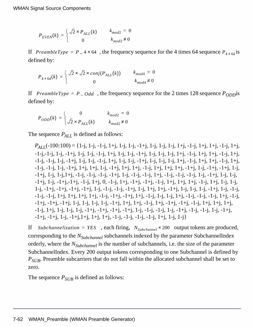
WMAN Signal Source Components
If , the frequency sequence for the 4 times 64 sequence is
defined by:
If , the frequency sequence for the 2 times 128 sequence PODDis
defined by:
The sequence PALL is defined as follows:
PALL(-100:100) = {1-j, 1-j, -1-j, 1+j, 1-j, 1-j, -1+j, 1-j, 1-j, 1-j, 1+j, -1-j, 1+j, 1+j, -1-j, 1+j,
-1-j,-1-j, 1-j, -1+j, 1-j, 1-j, -1-j, 1+j, 1-j, 1-j, -1+j, 1-j, 1-j, 1-j, 1+j, -1-j, 1+j, 1+j, -1-j, 1+j, -1-j, -1-j, 1-j, -1+j, 1-j, 1-j, -1-j, 1+j, 1-j, 1-j, -1+j, 1-j, 1-j, 1-j, 1+j, -1-j, 1+j, 1+j, -1-j, 1+j, -1-j, -1-j, 1-j, -1+j, 1+j, 1+j, 1-j, -1+j, 1+j, 1+j, -1-j, 1+j, 1+j, 1+j, -1+j, 1-j, -1+j, -1+j, 1-j, -1+j, 1-j, 1-j,1+j, -1-j, -1-j, -1-j, -1+j, 1-j, -1-j, -1-j, 1+j, -1-j, -1-j, -1-j, 1-j, -1+j, 1-j, 1-j, -1+j, 1-j, -1+j,-1+j, -1-j, 1+j, 0, -1-j, 1+j, -1+j, -1+j, -1-j, 1+j, 1+j, 1+j, -1-j, 1+j, 1-j, 1-j, 1-j, -1+j, -1+j, -1+j, -1+j, 1-j, -1-j, -1-j, -1+j, 1-j, 1+j, 1+j, -1+j, 1-j, 1-j, 1-j, -1+j, 1-j, -1-j, -1-j, -1-j, 1+j, 1+j, 1+j, 1+j, -1-j, -1+j, -1+j, 1+j, -1-j, 1-j, 1-j, 1+j, -1-j, -1-j, -1-j, 1+j, -1-j, -1+j, -1+j, -1+j, 1-j, 1-j, 1-j, 1-j, -1+j, 1+j, 1+j, -1-j, 1+j, -1+j, -1+j, -1-j, 1+j, 1+j, 1+j, -1-j, 1+j, 1-j, 1-j, 1-j, -1+j, -1+j, -1+j, -1+j, 1-j, -1-j, -1-j, 1-j, -1+j, -1-j, -1-j, 1-j, -1+j, -1+j, -1+j, 1-j, -1+j,1+j, 1+j, 1+j, -1-j, -1-j, -1-j, -1-j, 1+j, 1-j, 1-j}
If , each firing, output tokens are produced,
corresponding to the NSubchannel subchannels indexed by the parameter SubchannelIndex
orderly, where the NSubchannel is the number of subchannels, i.e. the size of the parameter
SubchannelIndex. Every 200 output tokens corresponding to one Subchannel is defined by PSUB. Preamble subcarriers that do not fall within the allocated subchannel shall be set to
zero.
The sequence PSUB is defined as follows:
PEVEN k( )2 PALL k( )×
0
=kmod2 0=
kmod2 0≠
PreambleType P 4 64×–= P4 64×
P4 64× k( )2 2× conj PALL k( )( )×
0
=kmod4 0=
kmod4 0≠
PreambleType P Odd–=
PODD k( )0
2 PALL k( )×
=kmod2 0=
kmod2 0≠
Subchannelization YES= NSubchannel 200×
7-62 WMAN_Preamble (WMAN Preamble Generator)
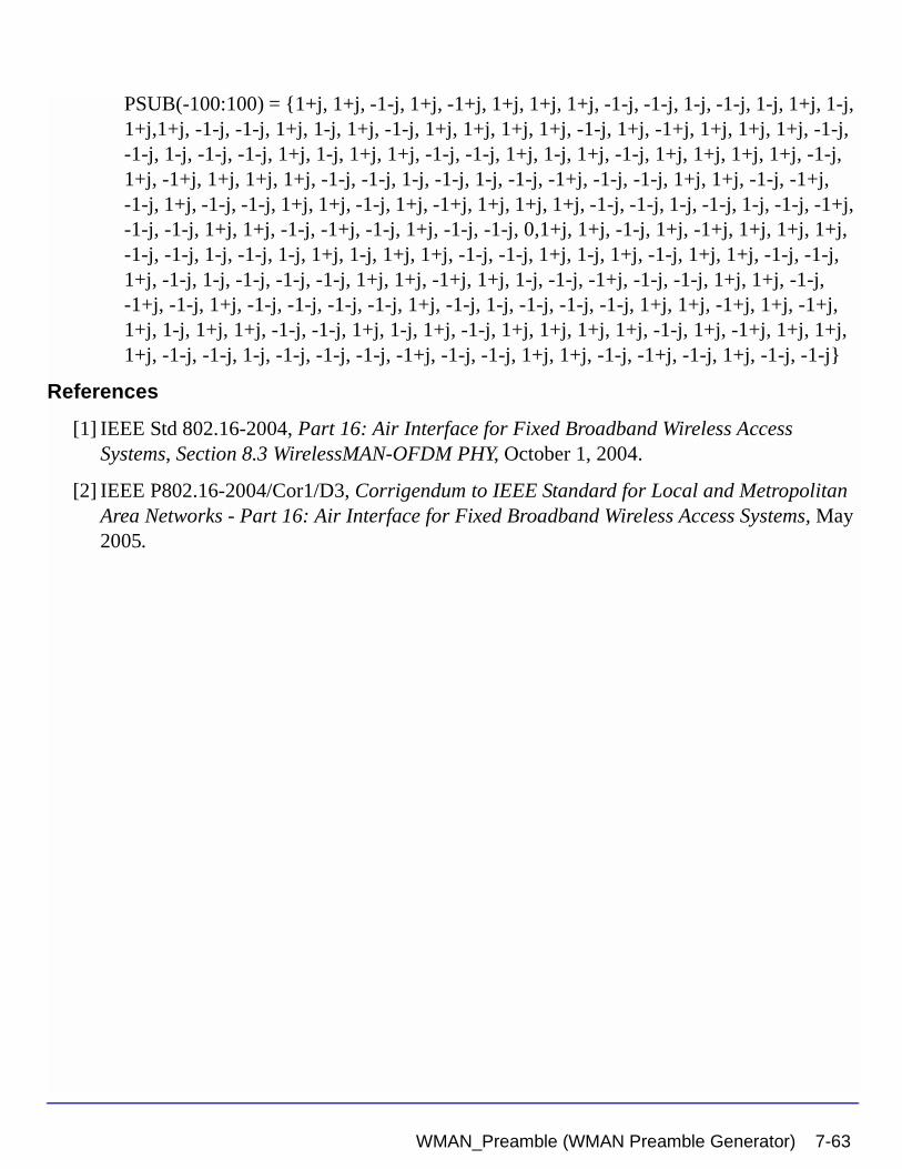
PSUB(-100:100) = {1+j, 1+j, -1-j, 1+j, -1+j, 1+j, 1+j, 1+j, -1-j, -1-j, 1-j, -1-j, 1-j, 1+j, 1-j, 1+j,1+j, -1-j, -1-j, 1+j, 1-j, 1+j, -1-j, 1+j, 1+j, 1+j, 1+j, -1-j, 1+j, -1+j, 1+j, 1+j, 1+j, -1-j, -1-j, 1-j, -1-j, -1-j, 1+j, 1-j, 1+j, 1+j, -1-j, -1-j, 1+j, 1-j, 1+j, -1-j, 1+j, 1+j, 1+j, 1+j, -1-j, 1+j, -1+j, 1+j, 1+j, 1+j, -1-j, -1-j, 1-j, -1-j, 1-j, -1-j, -1+j, -1-j, -1-j, 1+j, 1+j, -1-j, -1+j, -1-j, 1+j, -1-j, -1-j, 1+j, 1+j, -1-j, 1+j, -1+j, 1+j, 1+j, 1+j, -1-j, -1-j, 1-j, -1-j, 1-j, -1-j, -1+j, -1-j, -1-j, 1+j, 1+j, -1-j, -1+j, -1-j, 1+j, -1-j, -1-j, 0,1+j, 1+j, -1-j, 1+j, -1+j, 1+j, 1+j, 1+j, -1-j, -1-j, 1-j, -1-j, 1-j, 1+j, 1-j, 1+j, 1+j, -1-j, -1-j, 1+j, 1-j, 1+j, -1-j, 1+j, 1+j, -1-j, -1-j, 1+j, -1-j, 1-j, -1-j, -1-j, -1-j, 1+j, 1+j, -1+j, 1+j, 1-j, -1-j, -1+j, -1-j, -1-j, 1+j, 1+j, -1-j, -1+j, -1-j, 1+j, -1-j, -1-j, -1-j, -1-j, 1+j, -1-j, 1-j, -1-j, -1-j, -1-j, 1+j, 1+j, -1+j, 1+j, -1+j, 1+j, 1-j, 1+j, 1+j, -1-j, -1-j, 1+j, 1-j, 1+j, -1-j, 1+j, 1+j, 1+j, 1+j, -1-j, 1+j, -1+j, 1+j, 1+j, 1+j, -1-j, -1-j, 1-j, -1-j, -1-j, -1-j, -1+j, -1-j, -1-j, 1+j, 1+j, -1-j, -1+j, -1-j, 1+j, -1-j, -1-j}
References
[1] IEEE Std 802.16-2004, Part 16: Air Interface for Fixed Broadband Wireless Access Systems, Section 8.3 WirelessMAN-OFDM PHY, October 1, 2004.
[2] IEEE P802.16-2004/Cor1/D3, Corrigendum to IEEE Standard for Local and Metropolitan Area Networks - Part 16: Air Interface for Fixed Broadband Wireless Access Systems, May 2005.
WMAN_Preamble (WMAN Preamble Generator) 7-63
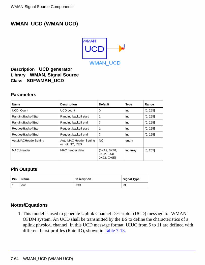
WMAN Signal Source Components
WMAN_UCD (WMAN UCD)
Description UCD generatorLibrary WMAN, Signal SourceClass SDFWMAN_UCD
Parameters
Pin Outputs
Notes/Equations
1. This model is used to generate Uplink Channel Descriptor (UCD) message for WMAN OFDM system. An UCD shall be transmitted by the BS to define the characteristics of a uplink physical channel. In this UCD message format, UIUC from 5 to 11 are defined with different burst profiles (Rate ID), shown in Table 7-13.
Name Description Default Type Range
UCD_Count UCD count 0 int [0, 255]
RangingBackoffStart Ranging backoff start 1 int [0, 255]
RangingBackoffEnd Ranging backoff end 7 int [0, 255]
RequestBackoffStart Request backoff start 1 int [0, 255]
RequestBackoffEnd Request backoff end 7 int [0, 255]
AutoMACHeaderSetting Auto MAC Header Setting or not: NO, YES
NO enum
MAC_Header MAC header data {0XA2, 0X48, 0X22, 0X4F, 0X93, 0X0E}
int array [0, 255]
Pin Name Description Signal Type
1 out UCD int
7-64 WMAN_UCD (WMAN UCD)
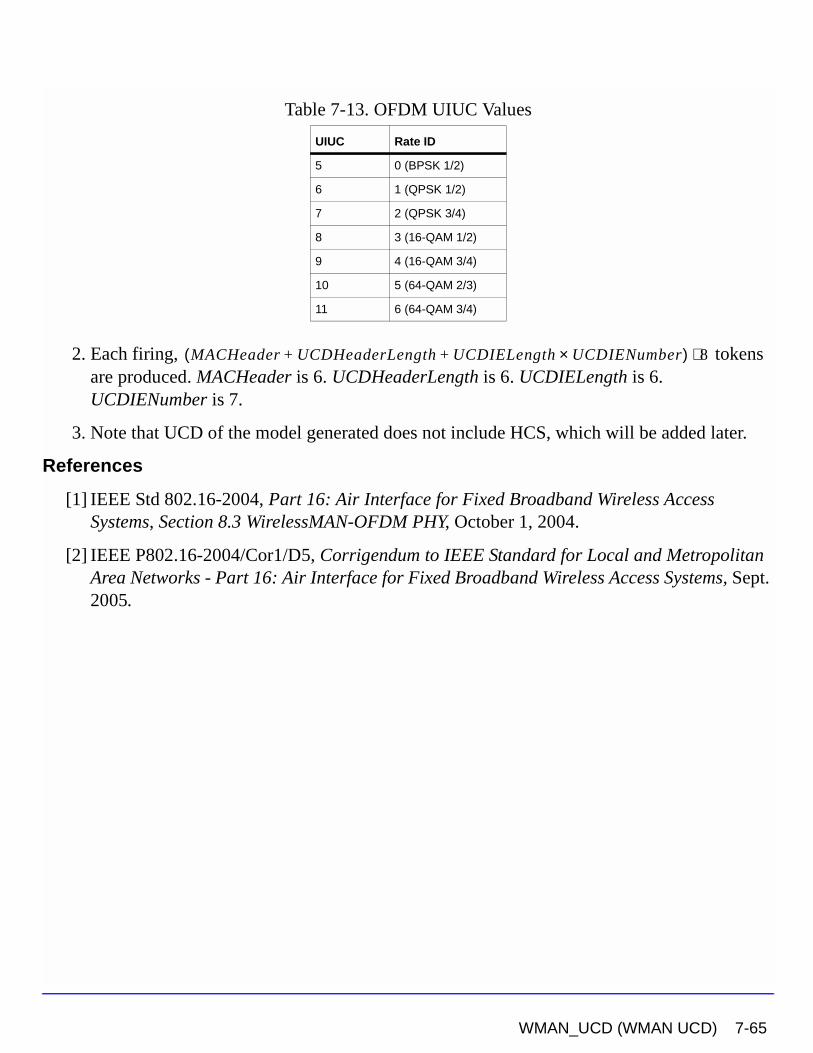
2. Each firing, tokens are produced. MACHeader is 6. UCDHeaderLength is 6. UCDIELength is 6. UCDIENumber is 7.
3. Note that UCD of the model generated does not include HCS, which will be added later.
References
[1] IEEE Std 802.16-2004, Part 16: Air Interface for Fixed Broadband Wireless Access Systems, Section 8.3 WirelessMAN-OFDM PHY, October 1, 2004.
[2] IEEE P802.16-2004/Cor1/D5, Corrigendum to IEEE Standard for Local and Metropolitan Area Networks - Part 16: Air Interface for Fixed Broadband Wireless Access Systems, Sept. 2005.
Table 7-13. OFDM UIUC Values
UIUC Rate ID
5 0 (BPSK 1/2)
6 1 (QPSK 1/2)
7 2 (QPSK 3/4)
8 3 (16-QAM 1/2)
9 4 (16-QAM 3/4)
10 5 (64-QAM 2/3)
11 6 (64-QAM 3/4)
MACHeader UCDHeaderLength UCDIELength UCDIENumber×+ +( ) 8⋅
WMAN_UCD (WMAN UCD) 7-65
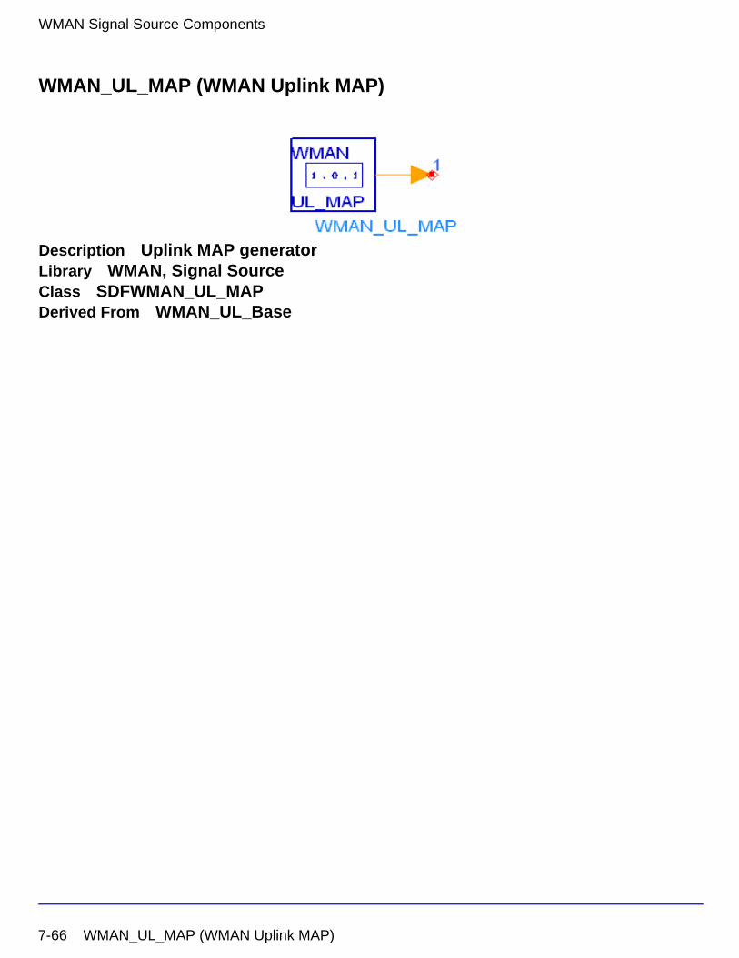
WMAN Signal Source Components
WMAN_UL_MAP (WMAN Uplink MAP)
Description Uplink MAP generatorLibrary WMAN, Signal SourceClass SDFWMAN_UL_MAPDerived From WMAN_UL_Base
7-66 WMAN_UL_MAP (WMAN Uplink MAP)
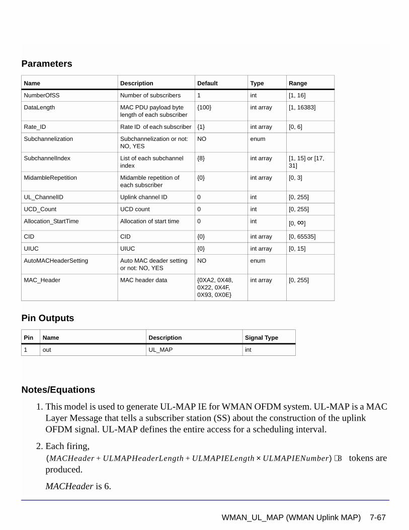
Parameters
Pin Outputs
Notes/Equations
1. This model is used to generate UL-MAP IE for WMAN OFDM system. UL-MAP is a MAC Layer Message that tells a subscriber station (SS) about the construction of the uplink OFDM signal. UL-MAP defines the entire access for a scheduling interval.
2. Each firing, tokens are
produced.
MACHeader is 6.
Name Description Default Type Range
NumberOfSS Number of subscribers 1 int [1, 16]
DataLength MAC PDU payload byte length of each subscriber
{100} int array [1, 16383]
Rate_ID Rate ID of each subscriber {1} int array [0, 6]
Subchannelization Subchannelization or not: NO, YES
NO enum
SubchannelIndex List of each subchannel index
{8} int array [1, 15] or [17, 31]
MidambleRepetition Midamble repetition of each subscriber
{0} int array [0, 3]
UL_ChannelID Uplink channel ID 0 int [0, 255]
UCD_Count UCD count 0 int [0, 255]
Allocation_StartTime Allocation of start time 0 int [0, ∞]
CID CID {0} int array [0, 65535]
UIUC UIUC {0} int array [0, 15]
AutoMACHeaderSetting Auto MAC deader setting or not: NO, YES
NO enum
MAC_Header MAC header data {0XA2, 0X48, 0X22, 0X4F, 0X93, 0X0E}
int array [0, 255]
Pin Name Description Signal Type
1 out UL_MAP int
MACHeader ULMAPHeaderLength ULMAPIELength ULMAPIENumber×+ +( ) 8⋅
WMAN_UL_MAP (WMAN Uplink MAP) 7-67
WMAN Signal Source Components
ULMAPHeaderLength is 7.
ULMAPIELength is 6.
ULMAPIENumber is which are the End MAP IE and the data bursts.
3. When AutoMACHeaderSetting is set to YES, the MAC header is calculated automatically. Otherwise the values in the parameter MAC_Header are used.
4. Note that UL-MAP of the model generated does not include HCS, which will be added later.
References
[1] IEEE Std 802.16-2004, Part 16: Air Interface for Fixed Broadband Wireless Access Systems, Section 8.3 WirelessMAN-OFDM PHY, October 1, 2004.
[2] IEEE P802.16-2004/Cor1/D5, Corrigendum to IEEE Standard for Local and Metropolitan Area Networks - Part 16: Air Interface for Fixed Broadband Wireless Access Systems, Sept. 2005.
NumberOfSS 1+
7-68 WMAN_UL_MAP (WMAN Uplink MAP)
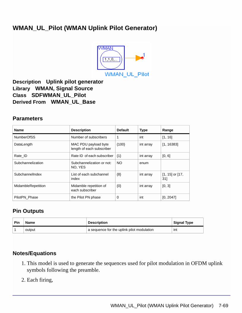
WMAN_UL_Pilot (WMAN Uplink Pilot Generator)
Description Uplink pilot generatorLibrary WMAN, Signal SourceClass SDFWMAN_UL_PilotDerived From WMAN_UL_Base
Parameters
Pin Outputs
Notes/Equations
1. This model is used to generate the sequences used for pilot modulation in OFDM uplink symbols following the preamble.
2. Each firing,
Name Description Default Type Range
NumberOfSS Number of subscribers 1 int [1, 16]
DataLength MAC PDU payload byte length of each subscriber
{100} int array [1, 16383]
Rate_ID Rate ID of each subscriber {1} int array [0, 6]
Subchannelization Subchannelization or not: NO, YES
NO enum
SubchannelIndex List of each subchannel index
{8} int array [1, 15] or [17, 31]
MidambleRepetition Midamble repetition of each subscriber
{0} int array [0, 3]
PilotPN_Phase the Pilot PN phase 0 int [0, 2047]
Pin Name Description Signal Type
1 output a sequence for the uplink pilot modulation int
WMAN_UL_Pilot (WMAN Uplink Pilot Generator) 7-69
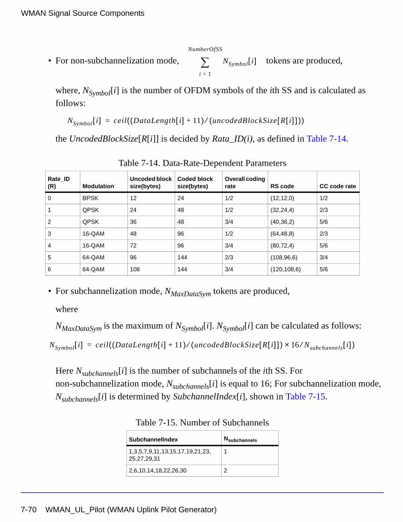
WMAN Signal Source Components
• For non-subchannelization mode, tokens are produced,
where, NSymbol[i] is the number of OFDM symbols of the ith SS and is calculated as
follows:
the UncodedBlockSize[R[i]] is decided by Rata_ID(i), as defined in Table 7-14.
• For subchannelization mode, NMaxDataSym tokens are produced,
where
NMaxDataSym is the maximum of NSymbol[i]. NSymbol[i] can be calculated as follows:
Here Nsubchannels[i] is the number of subchannels of the ith SS. For
non-subchannelization mode, Nsubchannels[i] is equal to 16; For subchannelization mode,
Nsubchannels[i] is determined by SubchannelIndex[i], shown in Table 7-15.
Table 7-14. Data-Rate-Dependent Parameters
Rate_ID(R) Modulation
Uncoded block size(bytes)
Coded block size(bytes)
Overall coding rate RS code CC code rate
0 BPSK 12 24 1/2 (12,12,0) 1/2
1 QPSK 24 48 1/2 (32,24,4) 2/3
2 QPSK 36 48 3/4 (40,36,2) 5/6
3 16-QAM 48 96 1/2 (64,48,8) 2/3
4 16-QAM 72 96 3/4 (80,72,4) 5/6
5 64-QAM 96 144 2/3 (108,96,6) 3/4
6 64-QAM 108 144 3/4 (120,108,6) 5/6
Table 7-15. Number of Subchannels
SubchannelIndex Nsubchannels
1,3,5,7,9,11,13,15,17,19,21,23,25,27,29,31
1
2,6,10,14,18,22,26,30 2
NSymbol i[ ]i 1=
NumberOfSS
∑
NSymbol i[ ] ceil DataLength i[ ] 11+( ) uncodedBlockSize R i[ ][ ]( )⁄( )=
NSymbol i[ ] ceil DataLength i[ ] 11+( ) uncodedBlockSize R i[ ][ ]( )⁄ 16 Nsubchannels⁄× i[ ]( )=
7-70 WMAN_UL_Pilot (WMAN Uplink Pilot Generator)
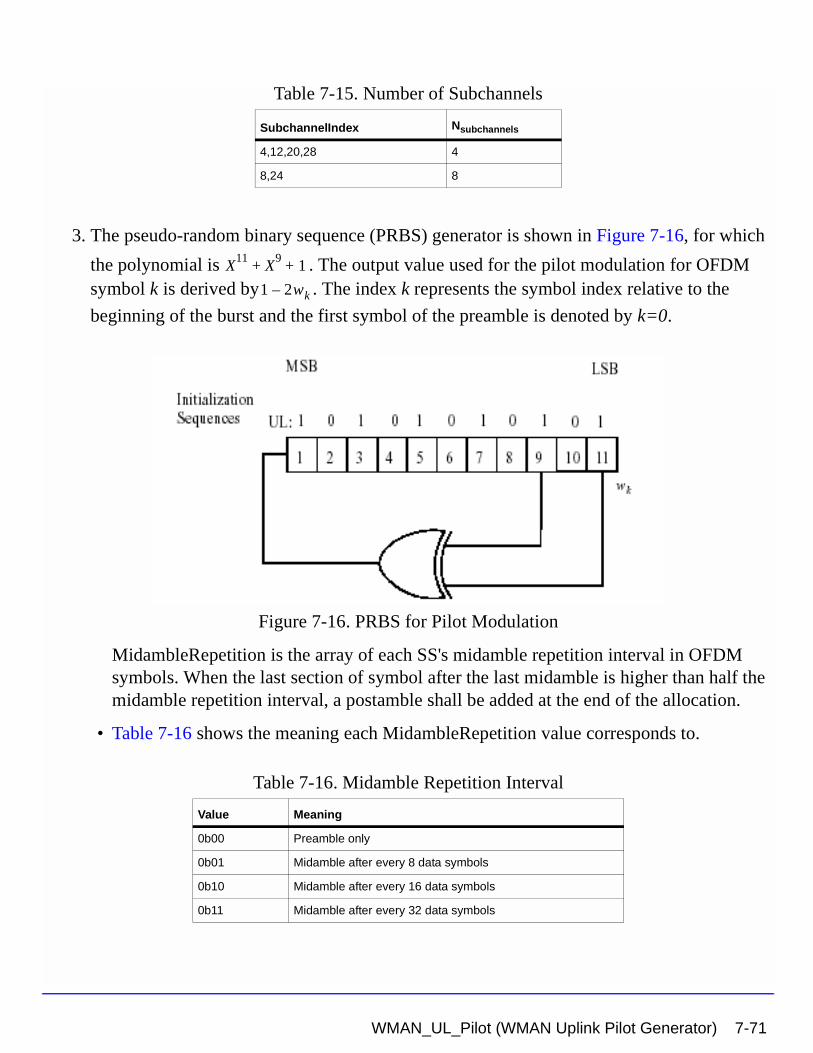
3. The pseudo-random binary sequence (PRBS) generator is shown in Figure 7-16, for which
the polynomial is . The output value used for the pilot modulation for OFDM symbol k is derived by . The index k represents the symbol index relative to the
beginning of the burst and the first symbol of the preamble is denoted by k=0.
Figure 7-16. PRBS for Pilot Modulation
MidambleRepetition is the array of each SS's midamble repetition interval in OFDM symbols. When the last section of symbol after the last midamble is higher than half the midamble repetition interval, a postamble shall be added at the end of the allocation.
• Table 7-16 shows the meaning each MidambleRepetition value corresponds to.
4,12,20,28 4
8,24 8
Table 7-16. Midamble Repetition Interval
Value Meaning
0b00 Preamble only
0b01 Midamble after every 8 data symbols
0b10 Midamble after every 16 data symbols
0b11 Midamble after every 32 data symbols
Table 7-15. Number of Subchannels
SubchannelIndex Nsubchannels
X11
X9
1+ +
1 2wk–
WMAN_UL_Pilot (WMAN Uplink Pilot Generator) 7-71
WMAN Signal Source Components
If one value in the array of MidamblePresent is set to nonzero, then the present midambles in this burst should be counted when the data symbols is indexed.
PilotPN_Phase specifies the start phase of pilots (PRBS). The specification requires PilotPN_Phase = 0.
References
[1] IEEE Std 802.16-2004, Part 16: Air Interface for Fixed Broadband Wireless Access Systems, Section 8.3 WirelessMAN-OFDM PHY, October 1, 2004.
[2] IEEE P802.16-2004/Cor1/D3, Corrigendum to IEEE Standard for Local and Metropolitan Area Networks - Part 16: Air Interface for Fixed Broadband Wireless Access Systems, May 2005.
7-72 WMAN_UL_Pilot (WMAN Uplink Pilot Generator)
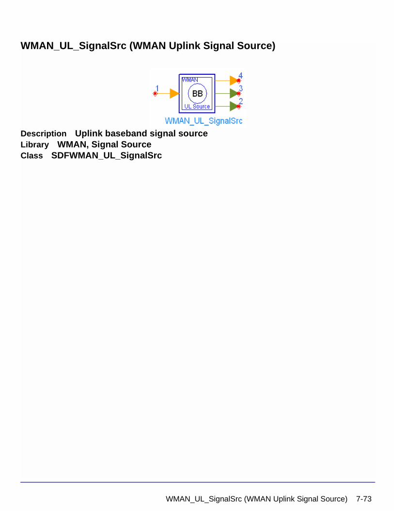
WMAN_UL_SignalSrc (WMAN Uplink Signal Source)
Description Uplink baseband signal sourceLibrary WMAN, Signal SourceClass SDFWMAN_UL_SignalSrc
WMAN_UL_SignalSrc (WMAN Uplink Signal Source) 7-73
WMAN Signal Source Components
Parameters
Pin Inputs
Name Description Default Unit Type Range
NumberOfSS Number of subscribers 1 int [1, 16]
SSWithFEC The number of subscriber with FEC
1 int [1, 16]
DataLength MAC PDU payload byte length of each subscriber
{100} int array [1, 4095]
Rate_ID Rate ID of each subscriber {1} int array [0, 6]
Subchannelization Subchannelization or not: NO, YES
NO enum
SubchannelIndex List of each subchannel index
{8} int array [1, 15] or [17, 31]
MidambleRepetition Midamble repetition of each subscriber
{0} int array [0, 3]
PrmlTimeShift Preamble time shift of each subscriber
{0} int array [0, 255]
TimeOffset Time offset of each subscriber
{0 usec} sec real array [0, IdleInterval]
UIUC UIUC of each subscriber {1} int [0, 15]
FrameNumber Frame Number 0 int [0, 15]
BSID BS ID 0 int [0, 15]
OversamplingOption Oversampling ratio option: Ratio 1, Ratio 2, Ratio 4, Ratio 8, Ratio 16, Ratio 32
Ratio 1 enum
Bandwidth Bandwidth 1.75 MHz Hz real (0, 1e9]
CyclicPrefix Cyclic prefix 0.25 real [0, 1]
IdleInterval Idle Interval 10 usec sec real [0, 1000]
PilotPN_Phase Pilot phase 0 int [0, 4095]
MAC_Header MAC header data {0XA2, 0X48, 0X22, 0X4F, 0X93, 0X0E}
int array [0, 255]
Power Power of each subscriber { 0.01 W } W real array (0, ∞)
Pin Name Description Signal Type
1 InputData input of raw data int
7-74 WMAN_UL_SignalSrc (WMAN Uplink Signal Source)
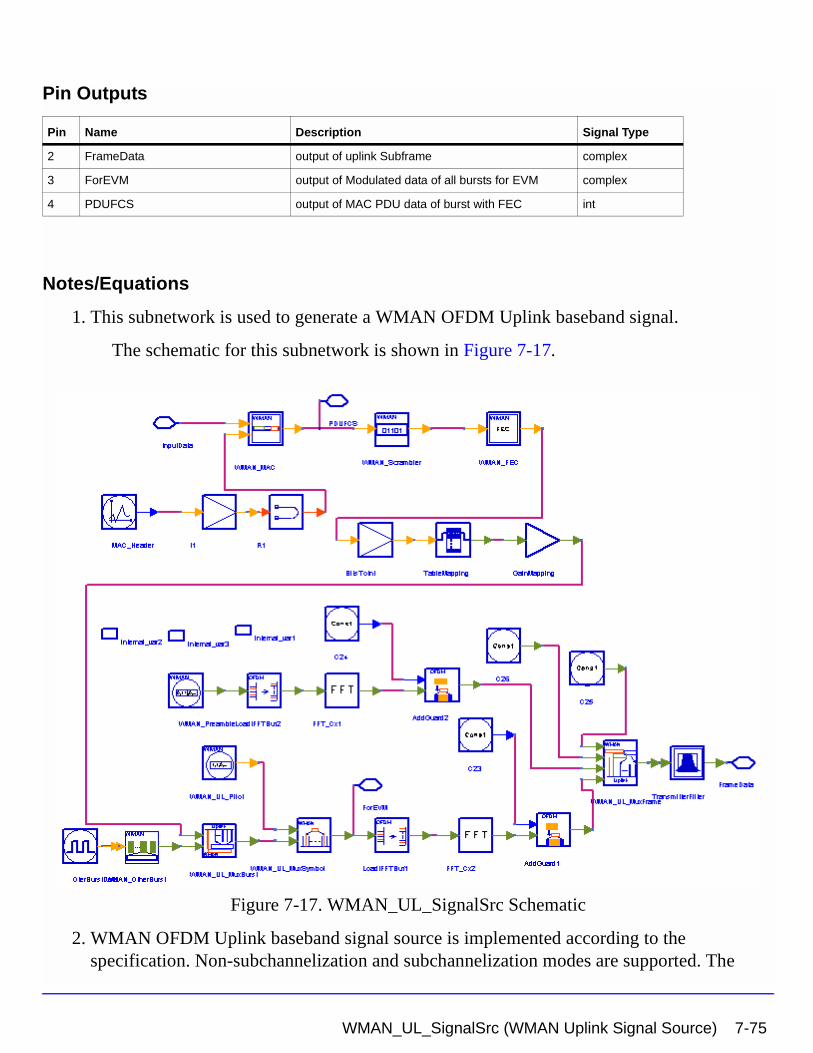
Pin Outputs
Notes/Equations
1. This subnetwork is used to generate a WMAN OFDM Uplink baseband signal.
The schematic for this subnetwork is shown in Figure 7-17.
Figure 7-17. WMAN_UL_SignalSrc Schematic
2. WMAN OFDM Uplink baseband signal source is implemented according to the specification. Non-subchannelization and subchannelization modes are supported. The
Pin Name Description Signal Type
2 FrameData output of uplink Subframe complex
3 ForEVM output of Modulated data of all bursts for EVM complex
4 PDUFCS output of MAC PDU data of burst with FEC int
WMAN_UL_SignalSrc (WMAN Uplink Signal Source) 7-75
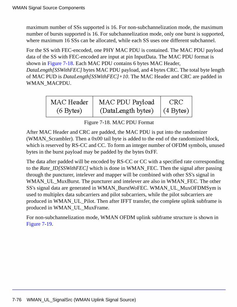
WMAN Signal Source Components
maximum number of SSs supported is 16. For non-subchannelization mode, the maximum number of bursts supported is 16. For subchannelization mode, only one burst is supported, where maximum 16 SSs can be allocated, while each SS uses one different subchannel.
For the SS with FEC-encoded, one PHY MAC PDU is contained. The MAC PDU payload data of the SS with FEC-encoded are input at pin InputData. The MAC PDU format is shown in Figure 7-18. Each MAC PDU contains 6 bytes MAC Header, DataLength[SSWithFEC] bytes MAC PDU payload, and 4 bytes CRC. The total byte length of MAC PUD is DataLength[SSWithFEC]+10. The MAC Header and CRC are padded in WMAN_MACPDU.
Figure 7-18. MAC PDU Format
After MAC Header and CRC are padded, the MAC PDU is put into the randomizer (WMAN_Scrambler). Then a 0x00 tail byte is added to the end of the randomized block, which is reserved by RS-CC and CC. To form an integer number of OFDM symbols, unused bytes in the burst payload may be padded by the bytes 0xFF.
The data after padded will be encoded by RS-CC or CC with a specified rate corresponding to the Rate_ID[SSWithFEC] which is done in WMAN_FEC. Then the signal after passing through the puncturer, intelever and mapper will be combined with other SS's signal in WMAN_UL_MuxBurst. The puncturer and intelever are also in WMAN_FEC. The other SS's signal data are generated in WMAN_BurstWoFEC. WMAN_UL_MuxOFDMSym is used to multiplex data subcarriers and pilot subcarriers, while the pilot subcarriers are produced in WMAN_UL_Pilot. Then after IFFT transfer, the complete uplink subframe is produced in WMAN_UL_MuxFrame.
For non-subchannelization mode, WMAN OFDM uplink subframe structure is shown in Figure 7-19.
7-76 WMAN_UL_SignalSrc (WMAN Uplink Signal Source)
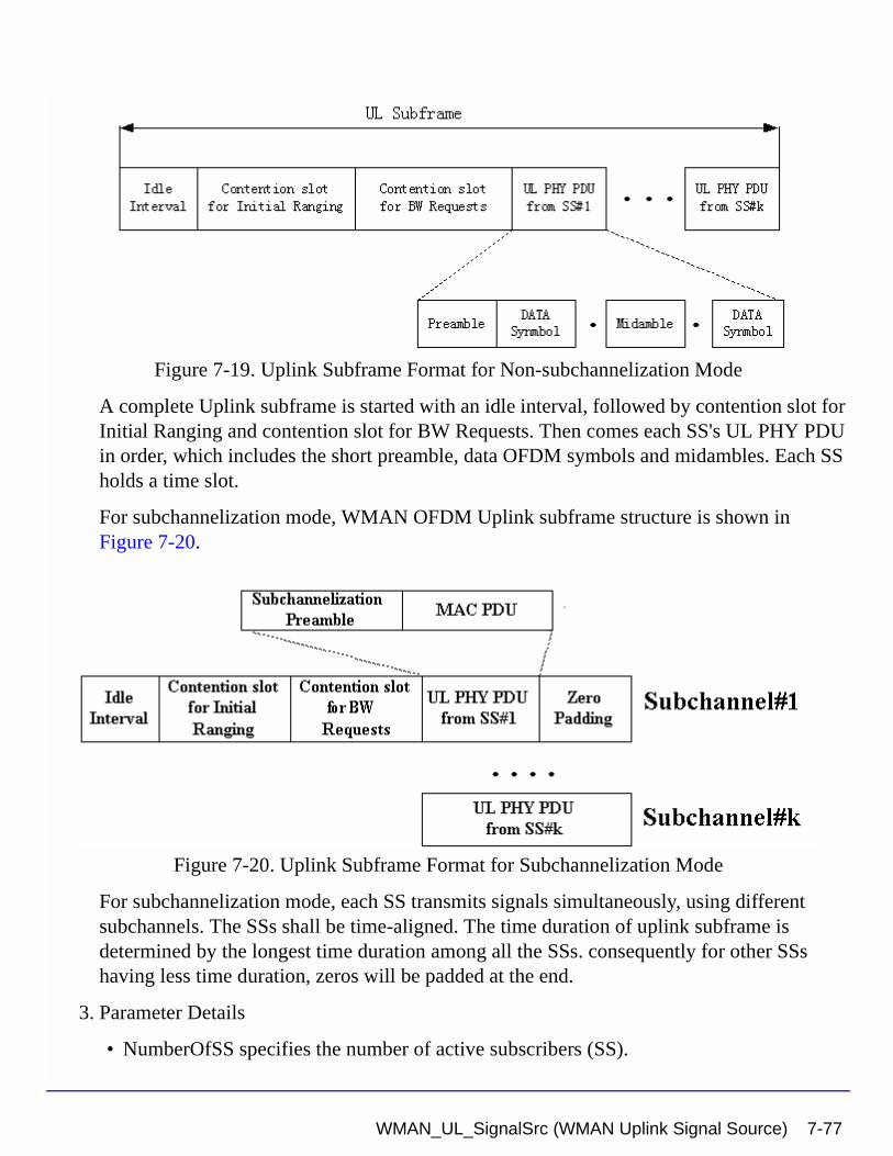
Figure 7-19. Uplink Subframe Format for Non-subchannelization Mode
A complete Uplink subframe is started with an idle interval, followed by contention slot for Initial Ranging and contention slot for BW Requests. Then comes each SS's UL PHY PDU in order, which includes the short preamble, data OFDM symbols and midambles. Each SS holds a time slot.
For subchannelization mode, WMAN OFDM Uplink subframe structure is shown in Figure 7-20.
Figure 7-20. Uplink Subframe Format for Subchannelization Mode
For subchannelization mode, each SS transmits signals simultaneously, using different subchannels. The SSs shall be time-aligned. The time duration of uplink subframe is determined by the longest time duration among all the SSs. consequently for other SSs having less time duration, zeros will be padded at the end.
3. Parameter Details
• NumberOfSS specifies the number of active subscribers (SS).
WMAN_UL_SignalSrc (WMAN Uplink Signal Source) 7-77
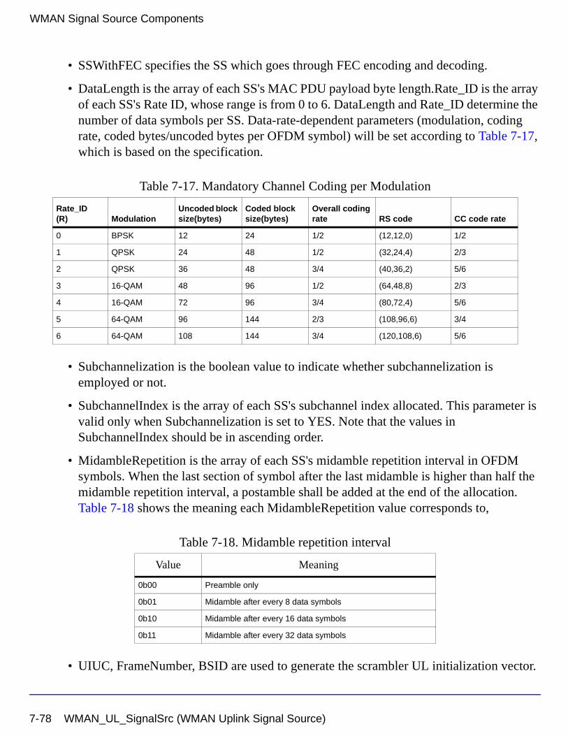
WMAN Signal Source Components
• SSWithFEC specifies the SS which goes through FEC encoding and decoding.
• DataLength is the array of each SS's MAC PDU payload byte length.Rate_ID is the array of each SS's Rate ID, whose range is from 0 to 6. DataLength and Rate_ID determine the number of data symbols per SS. Data-rate-dependent parameters (modulation, coding rate, coded bytes/uncoded bytes per OFDM symbol) will be set according to Table 7-17, which is based on the specification.
• Subchannelization is the boolean value to indicate whether subchannelization is employed or not.
• SubchannelIndex is the array of each SS's subchannel index allocated. This parameter is valid only when Subchannelization is set to YES. Note that the values in SubchannelIndex should be in ascending order.
• MidambleRepetition is the array of each SS's midamble repetition interval in OFDM symbols. When the last section of symbol after the last midamble is higher than half the midamble repetition interval, a postamble shall be added at the end of the allocation. Table 7-18 shows the meaning each MidambleRepetition value corresponds to,
• UIUC, FrameNumber, BSID are used to generate the scrambler UL initialization vector.
Table 7-17. Mandatory Channel Coding per Modulation
Rate_ID(R) Modulation
Uncoded block size(bytes)
Coded block size(bytes)
Overall coding rate RS code CC code rate
0 BPSK 12 24 1/2 (12,12,0) 1/2
1 QPSK 24 48 1/2 (32,24,4) 2/3
2 QPSK 36 48 3/4 (40,36,2) 5/6
3 16-QAM 48 96 1/2 (64,48,8) 2/3
4 16-QAM 72 96 3/4 (80,72,4) 5/6
5 64-QAM 96 144 2/3 (108,96,6) 3/4
6 64-QAM 108 144 3/4 (120,108,6) 5/6
Table 7-18. Midamble repetition interval
Value Meaning
0b00 Preamble only
0b01 Midamble after every 8 data symbols
0b10 Midamble after every 16 data symbols
0b11 Midamble after every 32 data symbols
7-78 WMAN_UL_SignalSrc (WMAN Uplink Signal Source)
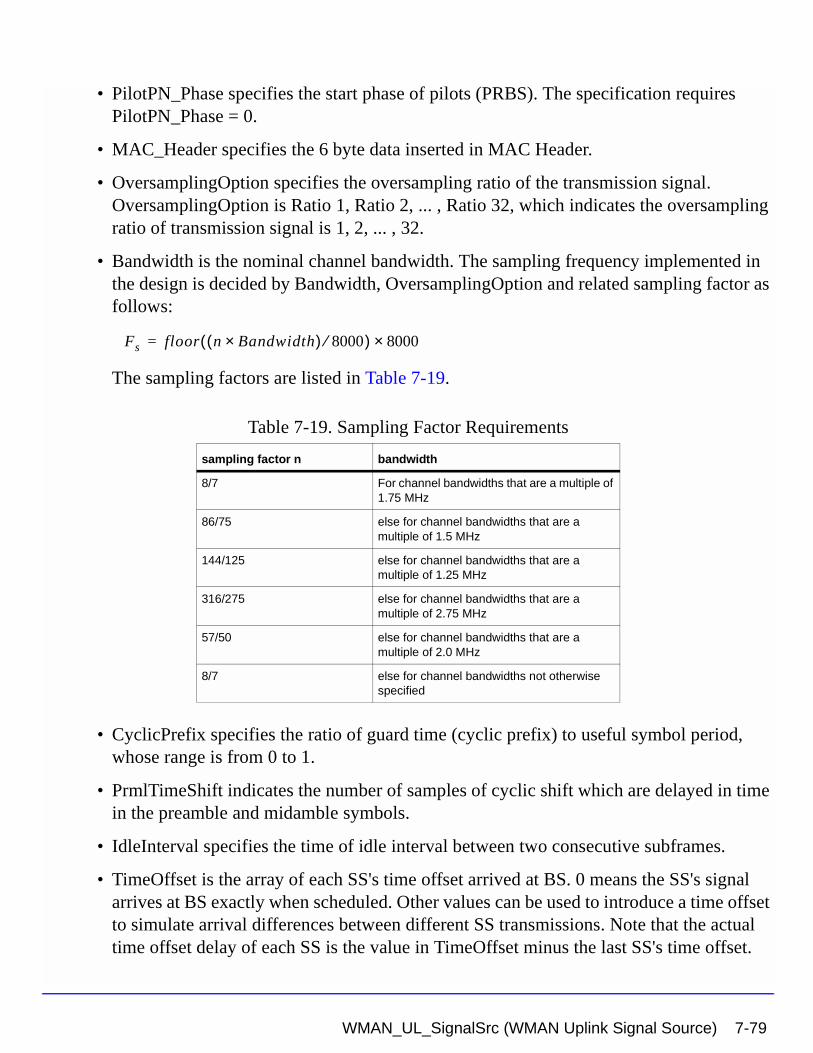
• PilotPN_Phase specifies the start phase of pilots (PRBS). The specification requires PilotPN_Phase = 0.
• MAC_Header specifies the 6 byte data inserted in MAC Header.
• OversamplingOption specifies the oversampling ratio of the transmission signal. OversamplingOption is Ratio 1, Ratio 2, ... , Ratio 32, which indicates the oversampling ratio of transmission signal is 1, 2, ... , 32.
• Bandwidth is the nominal channel bandwidth. The sampling frequency implemented in the design is decided by Bandwidth, OversamplingOption and related sampling factor as follows:
The sampling factors are listed in Table 7-19.
• CyclicPrefix specifies the ratio of guard time (cyclic prefix) to useful symbol period, whose range is from 0 to 1.
• PrmlTimeShift indicates the number of samples of cyclic shift which are delayed in time in the preamble and midamble symbols.
• IdleInterval specifies the time of idle interval between two consecutive subframes.
• TimeOffset is the array of each SS's time offset arrived at BS. 0 means the SS's signal arrives at BS exactly when scheduled. Other values can be used to introduce a time offset to simulate arrival differences between different SS transmissions. Note that the actual time offset delay of each SS is the value in TimeOffset minus the last SS's time offset.
Table 7-19. Sampling Factor Requirements
sampling factor n bandwidth
8/7 For channel bandwidths that are a multiple of 1.75 MHz
86/75 else for channel bandwidths that are a multiple of 1.5 MHz
144/125 else for channel bandwidths that are a multiple of 1.25 MHz
316/275 else for channel bandwidths that are a multiple of 2.75 MHz
57/50 else for channel bandwidths that are a multiple of 2.0 MHz
8/7 else for channel bandwidths not otherwise specified
Fs floor n Bandwidth×( ) 8000⁄( ) 8000×=
WMAN_UL_SignalSrc (WMAN Uplink Signal Source) 7-79
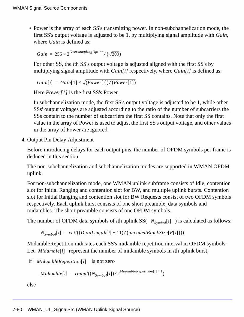
WMAN Signal Source Components
• Power is the array of each SS's transmitting power. In non-subchannelization mode, the first SS's output voltage is adjusted to be 1, by multiplying signal amplitude with Gain, where Gain is defined as:
For other SS, the ith SS's output voltage is adjusted aligned with the first SS's by multiplying signal amplitude with Gain[i] respectively, where Gain[i] is defined as:
Here Power[1] is the first SS's Power.
In subchannelization mode, the first SS's output voltage is adjusted to be 1, while other SSs' output voltages are adjusted according to the ratio of the number of subcarriers the SSs contain to the number of subcarriers the first SS contains. Note that only the first value in the array of Power is used to adjust the first SS's output voltage, and other values in the array of Power are ignored.
4. Output Pin Delay Adjustment
Before introducing delays for each output pins, the number of OFDM symbols per frame is deduced in this section.
The non-subchannelization and subchannelization modes are supported in WMAN OFDM uplink.
For non-subchannelization mode, one WMAN uplink subframe consists of Idle, contention slot for Initial Ranging and contention slot for BW, and multiple uplink bursts. Contention slot for Initial Ranging and contention slot for BW Requests consist of two OFDM symbols respectively. Each uplink burst consists of one short preamble, data symbols and midambles. The short preamble consists of one OFDM symbols.
The number of OFDM data symbols of ith uplink SS( ) is calculated as follows:
MidambleRepetition indicates each SS's midamble repetition interval in OFDM symbols. Let represent the number of midamble symbols in ith uplink burst,
if is not zero
else
Gain 256 2OversamplingOption
200( )⁄×=
Gain i[ ] Gain 1[ ] Power i[ ]( ) Power 1[ ]( )⁄×=
NSymbol i[ ]
NSymbol i[ ] ceil DataLength i[ ] 11+( ) uncodedBlockSize R i[ ][ ]( )⁄( )=
Midamble i[ ]
MidambleRepetition i[ ]
Midamble i[ ] round NSymbol i[ ]( ) 2MidambleRepetition i[ ] 1+⁄( )=
7-80 WMAN_UL_SignalSrc (WMAN Uplink Signal Source)
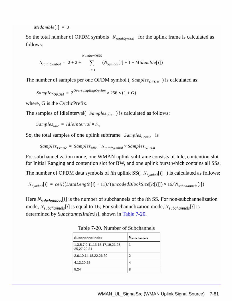
So the total number of OFDM symbols for the uplink frame is calculated as
follows:
The number of samples per one OFDM symbol ( ) is calculated as:
where, G is the CyclicPrefix.
The samples of IdleInterval( ) is calculated as follows:
So, the total samples of one uplink subframe is
For subchannelization mode, one WMAN uplink subframe consists of Idle, contention slot for Initial Ranging and contention slot for BW, and one uplink burst which contains all SSs.
The number of OFDM data symbols of ith uplink SS( ) is calculated as follows:
Here Nsubchannels[i] is the number of subchannels of the ith SS. For non-subchannelization
mode, Nsubchannels[i] is equal to 16; For subchannelization mode, Nsubchannels[i] is
determined by SubchannelIndex[i], shown in Table 7-20.
Table 7-20. Number of Subchannels
SubchannelIndex Nsubchannels
1,3,5,7,9,11,13,15,17,19,21,23,25,27,29,31
1
2,6,10,14,18,22,26,30 2
4,12,20,28 4
8,24 8
Midamble i[ ] 0=
NtotalSymbol
NtotalSymbol 2 2 NSymbol i[ ] 1 Midamble i[ ]+ +( )i 1=
NumberOfSS
∑+ +=
SamplesOFDM
SamplesOFDM 2OversamplingOption
256× 1 G+( )×=
Samplesidle
Samplesidle IdleInterval Fs×=
SamplesFrame
SamplesFrame Samplesidle NtotalSymbol SamplesOFDM×+=
NSymbol i[ ]
NSymbol i[ ] ceil DataLength i[ ] 11+( ) uncodedBlockSize R i[ ][ ]( )⁄ 16 Nsubchannels⁄× i[ ]( )=
WMAN_UL_SignalSrc (WMAN Uplink Signal Source) 7-81
WMAN Signal Source Components
So the total number of OFDM symbols for the uplink frame is calculated as
follows:
So, the total samples of one uplink subframe is
In the source, delay is introduced by the transmitter filter in the design WMAN_UL_SignalSrc, where the delay is equal to . Length is the parameter in the transmitter filter.
References
[1] IEEE Std 802.16-2004, Part 16: Air Interface for Fixed Broadband Wireless Access Systems, Section 8.3 WirelessMAN-OFDM PHY, October 1, 2004.
[2] IEEE P802.16-2004/Cor1/D3, Corrigendum to IEEE Standard for Local and Metropolitan Area Networks - Part 16: Air Interface for Fixed Broadband Wireless Access Systems, May 2005.
NtotalSymbol
NtotalSymbol 2 2 max NSymbol i[ ] 1 Midamble i[ ]+ +( )+ +=
SamplesFrame
SamplesFrame Samplesidle NtotalSymbol SamplesOFDM×+=
30 2oversamplingOption×
Length 1–( ) 2⁄
7-82 WMAN_UL_SignalSrc (WMAN Uplink Signal Source)
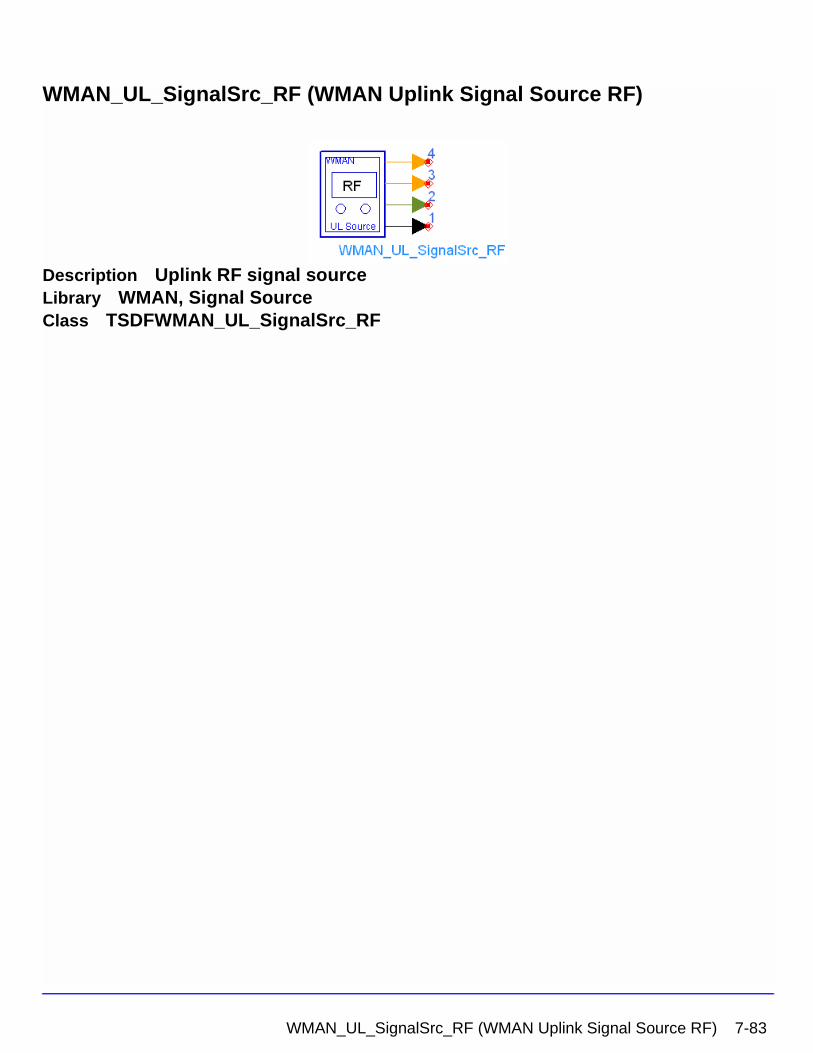
WMAN_UL_SignalSrc_RF (WMAN Uplink Signal Source RF)
Description Uplink RF signal sourceLibrary WMAN, Signal SourceClass TSDFWMAN_UL_SignalSrc_RF
WMAN_UL_SignalSrc_RF (WMAN Uplink Signal Source RF) 7-83
WMAN Signal Source Components
Parameters
Name Description Default Unit Type Range
ROut Source resistance 50 Ohm Ohm int (0, ∞)
RTemp TEMPERATURE - 273.15 Celsius real [- 273.15, ∞]
FCarrier Carrier frequency 3407 MHz Hz real (0, ∞)
Power Power of each subscriber { 0.01 W } W real array (0, ∞)
MirrorSpectrum Indication of mirror spectrum about carrier: NO, YES
NO enum
GainImbalance Gain imbalance in dB Q channel relative to I channel
0.0 real (-∞, ∞)
PhaseImbalance Phase imbalance in dB Q channel relative to I channel
0.0 real (-∞, ∞)
I_OriginOffset I origin offset in percent with repect to output rms voltage
0.0 real (-∞, ∞)
Q_OriginOffset q origin offset in percent with repect to output rms voltage
0.0 real (-∞, ∞)
IQ_Rotation IQ rotation in degrees 0.0 real (-∞, ∞)
NumberOfSS Number of subscribers 1 int [1, 16]
SSWithFEC The number of subscriber with FEC
1 int [1, 16]
DataLength MAC PDU payload byte length of each subscriber
{100} int array [1, 4095]
Rate_ID Rate ID of each subscriber {1} int array [0, 6]
Subchannelization Subchannelization or not: NO, YES
NO enum
SubchannelIndex List of each subchannel index
{8} int array [1, 15] or [17, 31]
MidambleRepetition Midamble repetition of each subscriber
{0} int array [0, 3]
PrmlTimeShift Preamble time shift of each subscriber
{0} int array [0, 255]
TimeOffset Time offset of each subscriber
{0 usec} sec real array [0, IdleInterval]
UIUC UIUC of each subscriber {1} int [0, 15]
FrameNumber Frame Number 0 int [0, 15]
7-84 WMAN_UL_SignalSrc_RF (WMAN Uplink Signal Source RF)
Pin Outputs
Notes/Equations
1. This subnetwork is used to integrates an RF modulator with the baseband signal source. The WMAN OFDM uplink baseband signal is fed into the RF modulator. The RF signal is timed signal after RF modulation.
The schematic for this subnetwork is shown in Figure 7-21.
BSID BS ID 0 int [0, 15]
OversamplingOption Oversampling ratio option: Ratio 1, Ratio 2, Ratio 4, Ratio 8, Ratio 16, Ratio 32
Ratio 1 enum
Bandwidth Bandwidth 1.75 MHz Hz real (0, 1e9]
CyclicPrefix Cyclic prefix 0.25 real [0, 1]
IdleInterval Idle Interval 10 usec sec real [0, 1000]
PilotPN_Phase Pilot phase 0 int [0, 4095]
DataPattern WMAN Data Pattern: PN9, PN15, FIX4, _4_1_4_0, _8_1_8_0, _16_1_16_0, _32_1_32_0, _64_1_64_0, S_BPSK, S_QPSK, S_16-QAM, S_64-QAM
PN9 enum
MAC_Header MAC header data {0XA2, 0X48, 0X22, 0X4F, 0X93, 0X0E}
int array [0, 255]
Pin Name Description Signal Type
1 RF_Signal output of RF signal timed
2 ForEVM output of Modulated data of all bursts for EVM complex
3 PDUFCS output of MAC PDU data of burst with FEC int
4 PSDU output of PSDU bits int
Name Description Default Unit Type Range
WMAN_UL_SignalSrc_RF (WMAN Uplink Signal Source RF) 7-85
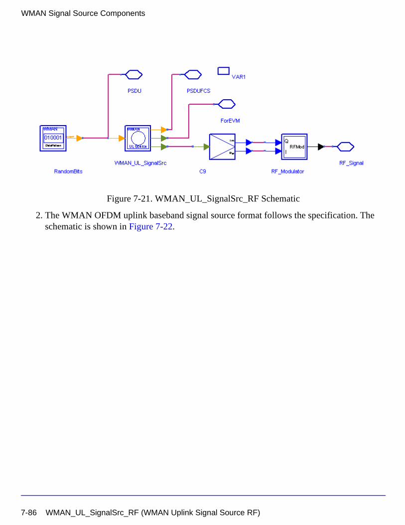
WMAN Signal Source Components
Figure 7-21. WMAN_UL_SignalSrc_RF Schematic
2. The WMAN OFDM uplink baseband signal source format follows the specification. The schematic is shown in Figure 7-22.
7-86 WMAN_UL_SignalSrc_RF (WMAN Uplink Signal Source RF)
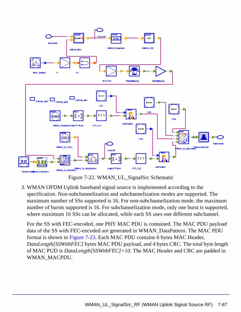
Figure 7-22. WMAN_UL_SignalSrc Schematic
3. WMAN OFDM Uplink baseband signal source is implemented according to the specification. Non-subchannelization and subchannelization modes are supported. The maximum number of SSs supported is 16. For non-subchannelization mode, the maximum number of bursts supported is 16. For subchannelization mode, only one burst is supported, where maximum 16 SSs can be allocated, while each SS uses one different subchannel.
For the SS with FEC-encoded, one PHY MAC PDU is contained. The MAC PDU payload data of the SS with FEC-encoded are generated in WMAN_DataPattern. The MAC PDU format is shown in Figure 7-23. Each MAC PDU contains 6 bytes MAC Header, DataLength[SSWithFEC] bytes MAC PDU payload, and 4 bytes CRC. The total byte length of MAC PUD is DataLength[SSWithFEC]+10. The MAC Header and CRC are padded in WMAN_MACPDU.
WMAN_UL_SignalSrc_RF (WMAN Uplink Signal Source RF) 7-87
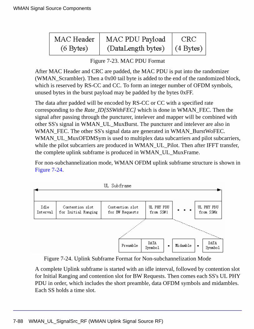
WMAN Signal Source Components
Figure 7-23. MAC PDU Format
After MAC Header and CRC are padded, the MAC PDU is put into the randomizer (WMAN_Scrambler). Then a 0x00 tail byte is added to the end of the randomized block, which is reserved by RS-CC and CC. To form an integer number of OFDM symbols, unused bytes in the burst payload may be padded by the bytes 0xFF.
The data after padded will be encoded by RS-CC or CC with a specified rate corresponding to the Rate_ID[SSWithFEC] which is done in WMAN_FEC. Then the signal after passing through the puncturer, intelever and mapper will be combined with other SS's signal in WMAN_UL_MuxBurst. The puncturer and intelever are also in WMAN_FEC. The other SS's signal data are generated in WMAN_BurstWoFEC. WMAN_UL_MuxOFDMSym is used to multiplex data subcarriers and pilot subcarriers, while the pilot subcarriers are produced in WMAN_UL_Pilot. Then after IFFT transfer, the complete uplink subframe is produced in WMAN_UL_MuxFrame.
For non-subchannelization mode, WMAN OFDM uplink subframe structure is shown in Figure 7-24.
Figure 7-24. Uplink Subframe Format for Non-subchannelization Mode
A complete Uplink subframe is started with an idle interval, followed by contention slot for Initial Ranging and contention slot for BW Requests. Then comes each SS's UL PHY PDU in order, which includes the short preamble, data OFDM symbols and midambles. Each SS holds a time slot.
7-88 WMAN_UL_SignalSrc_RF (WMAN Uplink Signal Source RF)
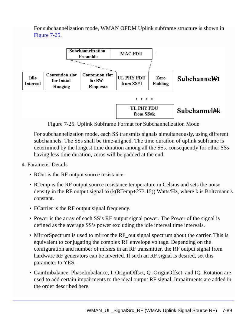
For subchannelization mode, WMAN OFDM Uplink subframe structure is shown in Figure 7-25.
Figure 7-25. Uplink Subframe Format for Subchannelization Mode
For subchannelization mode, each SS transmits signals simultaneously, using different subchannels. The SSs shall be time-aligned. The time duration of uplink subframe is determined by the longest time duration among all the SSs. consequently for other SSs having less time duration, zeros will be padded at the end.
4. Parameter Details
• ROut is the RF output source resistance.
• RTemp is the RF output source resistance temperature in Celsius and sets the noise density in the RF output signal to (k(RTemp+273.15)) Watts/Hz, where k is Boltzmann's constant.
• FCarrier is the RF output signal frequency.
• Power is the array of each SS’s RF output signal power. The Power of the signal is defined as the average SS’s power excluding the idle interval time intervals.
• MirrorSpectrum is used to mirror the RF_out signal spectrum about the carrier. This is equivalent to conjugating the complex RF envelope voltage. Depending on the configuration and number of mixers in an RF transmitter, the RF output signal from hardware RF generators can be inverted. If such an RF signal is desired, set this parameter to YES.
• GainImbalance, PhaseImbalance, I_OriginOffset, Q_OriginOffset, and IQ_Rotation are used to add certain impairments to the ideal output RF signal. Impairments are added in the order described here.
WMAN_UL_SignalSrc_RF (WMAN Uplink Signal Source RF) 7-89
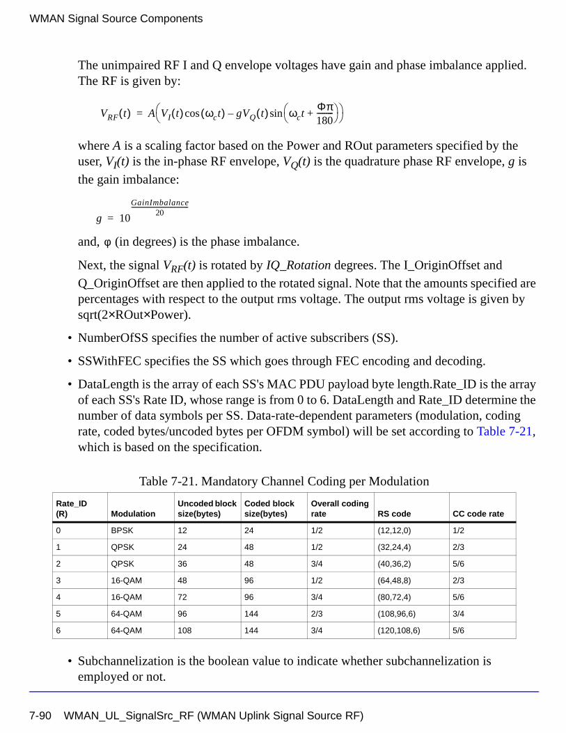
WMAN Signal Source Components
The unimpaired RF I and Q envelope voltages have gain and phase imbalance applied. The RF is given by:
where A is a scaling factor based on the Power and ROut parameters specified by the user, VI(t) is the in-phase RF envelope, VQ(t) is the quadrature phase RF envelope, g is
the gain imbalance:
and, (in degrees) is the phase imbalance.
Next, the signal VRF(t) is rotated by IQ_Rotation degrees. The I_OriginOffset and
Q_OriginOffset are then applied to the rotated signal. Note that the amounts specified are percentages with respect to the output rms voltage. The output rms voltage is given by sqrt(2×ROut×Power).
• NumberOfSS specifies the number of active subscribers (SS).
• SSWithFEC specifies the SS which goes through FEC encoding and decoding.
• DataLength is the array of each SS's MAC PDU payload byte length.Rate_ID is the array of each SS's Rate ID, whose range is from 0 to 6. DataLength and Rate_ID determine the number of data symbols per SS. Data-rate-dependent parameters (modulation, coding rate, coded bytes/uncoded bytes per OFDM symbol) will be set according to Table 7-21, which is based on the specification.
• Subchannelization is the boolean value to indicate whether subchannelization is employed or not.
Table 7-21. Mandatory Channel Coding per Modulation
Rate_ID(R) Modulation
Uncoded block size(bytes)
Coded block size(bytes)
Overall coding rate RS code CC code rate
0 BPSK 12 24 1/2 (12,12,0) 1/2
1 QPSK 24 48 1/2 (32,24,4) 2/3
2 QPSK 36 48 3/4 (40,36,2) 5/6
3 16-QAM 48 96 1/2 (64,48,8) 2/3
4 16-QAM 72 96 3/4 (80,72,4) 5/6
5 64-QAM 96 144 2/3 (108,96,6) 3/4
6 64-QAM 108 144 3/4 (120,108,6) 5/6
VRF t( ) A VI t( ) ωct( )cos gVQ t( ) ωctΦπ180---------+
sin– =
g 10
GainImbalance20
-----------------------------------------
=
φ
7-90 WMAN_UL_SignalSrc_RF (WMAN Uplink Signal Source RF)
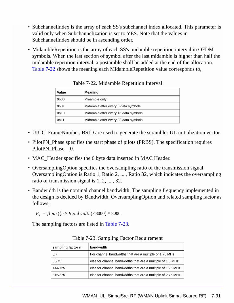
• SubchannelIndex is the array of each SS's subchannel index allocated. This parameter is valid only when Subchannelization is set to YES. Note that the values in SubchannelIndex should be in ascending order.
• MidambleRepetition is the array of each SS's midamble repetition interval in OFDM symbols. When the last section of symbol after the last midamble is higher than half the midamble repetition interval, a postamble shall be added at the end of the allocation. Table 7-22 shows the meaning each MidambleRepetition value corresponds to,
• UIUC, FrameNumber, BSID are used to generate the scrambler UL initialization vector.
• PilotPN_Phase specifies the start phase of pilots (PRBS). The specification requires PilotPN_Phase = 0.
• MAC_Header specifies the 6 byte data inserted in MAC Header.
• OversamplingOption specifies the oversampling ratio of the transmission signal. OversamplingOption is Ratio 1, Ratio 2, ... , Ratio 32, which indicates the oversampling ratio of transmission signal is 1, 2, ... , 32.
• Bandwidth is the nominal channel bandwidth. The sampling frequency implemented in the design is decided by Bandwidth, OversamplingOption and related sampling factor as follows:
The sampling factors are listed in Table 7-23.
Table 7-22. Midamble Repetition Interval
Value Meaning
0b00 Preamble only
0b01 Midamble after every 8 data symbols
0b10 Midamble after every 16 data symbols
0b11 Midamble after every 32 data symbols
Table 7-23. Sampling Factor Requirement
sampling factor n bandwidth
8/7 For channel bandwidths that are a multiple of 1.75 MHz
86/75 else for channel bandwidths that are a multiple of 1.5 MHz
144/125 else for channel bandwidths that are a multiple of 1.25 MHz
316/275 else for channel bandwidths that are a multiple of 2.75 MHz
Fs floor n Bandwidth×( ) 8000⁄( ) 8000×=
WMAN_UL_SignalSrc_RF (WMAN Uplink Signal Source RF) 7-91
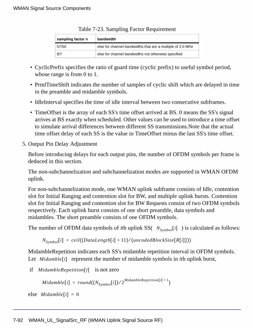
WMAN Signal Source Components
• CyclicPrefix specifies the ratio of guard time (cyclic prefix) to useful symbol period, whose range is from 0 to 1.
• PrmlTimeShift indicates the number of samples of cyclic shift which are delayed in time in the preamble and midamble symbols.
• IdleInterval specifies the time of idle interval between two consecutive subframes.
• TimeOffset is the array of each SS's time offset arrived at BS. 0 means the SS's signal arrives at BS exactly when scheduled. Other values can be used to introduce a time offset to simulate arrival differences between different SS transmissions.Note that the actual time offset delay of each SS is the value in TimeOffset minus the last SS's time offset.
5. Output Pin Delay Adjustment
Before introducing delays for each output pins, the number of OFDM symbols per frame is deduced in this section.
The non-subchannelization and subchannelization modes are supported in WMAN OFDM uplink.
For non-subchannelization mode, one WMAN uplink subframe consists of Idle, contention slot for Initial Ranging and contention slot for BW, and multiple uplink bursts. Contention slot for Initial Ranging and contention slot for BW Requests consist of two OFDM symbols respectively. Each uplink burst consists of one short preamble, data symbols and midambles. The short preamble consists of one OFDM symbols.
The number of OFDM data symbols of ith uplink SS( ) is calculated as follows:
MidambleRepetition indicates each SS's midamble repetition interval in OFDM symbols. Let represent the number of midamble symbols in ith uplink burst,
if is not zero
else
57/50 else for channel bandwidths that are a multiple of 2.0 MHz
8/7 else for channel bandwidths not otherwise specified
Table 7-23. Sampling Factor Requirement
sampling factor n bandwidth
NSymbol i[ ]
NSymbol i[ ] ceil DataLength i[ ] 11+( ) uncodedBlockSize R i[ ][ ]( )⁄( )=
Midamble i[ ]
MidambleRepetition i[ ]
Midamble i[ ] round NSymbol i[ ]( ) 2MidambleRepetition i[ ] 1+⁄( )=
Midamble i[ ] 0=
7-92 WMAN_UL_SignalSrc_RF (WMAN Uplink Signal Source RF)
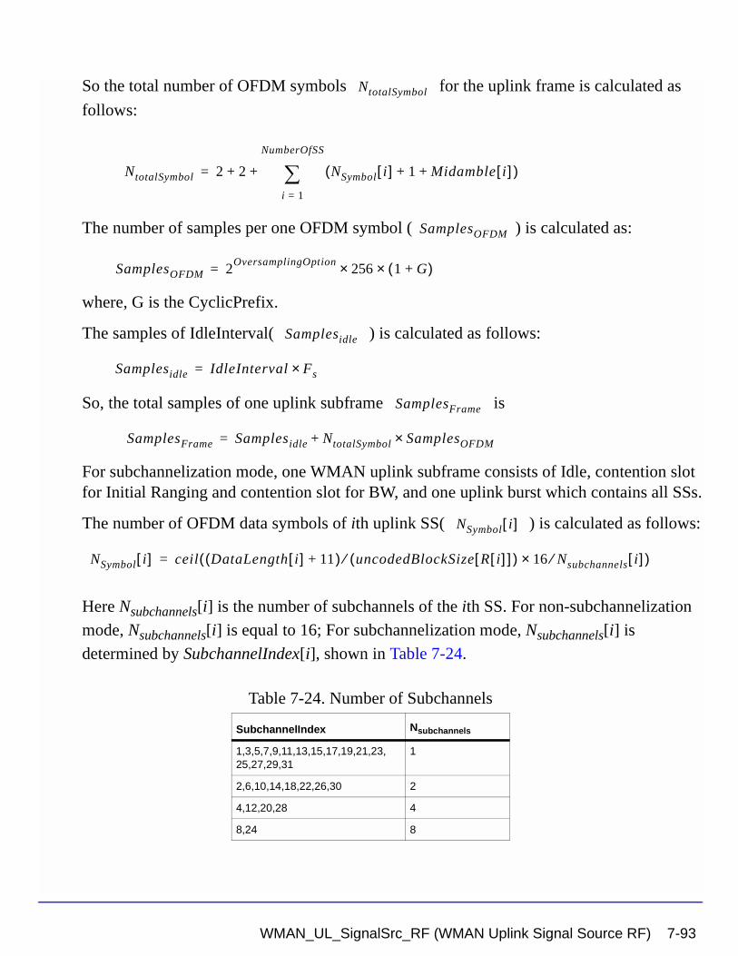
So the total number of OFDM symbols for the uplink frame is calculated as
follows:
The number of samples per one OFDM symbol ( ) is calculated as:
where, G is the CyclicPrefix.
The samples of IdleInterval( ) is calculated as follows:
So, the total samples of one uplink subframe is
For subchannelization mode, one WMAN uplink subframe consists of Idle, contention slot for Initial Ranging and contention slot for BW, and one uplink burst which contains all SSs.
The number of OFDM data symbols of ith uplink SS( ) is calculated as follows:
Here Nsubchannels[i] is the number of subchannels of the ith SS. For non-subchannelization
mode, Nsubchannels[i] is equal to 16; For subchannelization mode, Nsubchannels[i] is
determined by SubchannelIndex[i], shown in Table 7-24.
Table 7-24. Number of Subchannels
SubchannelIndex Nsubchannels
1,3,5,7,9,11,13,15,17,19,21,23,25,27,29,31
1
2,6,10,14,18,22,26,30 2
4,12,20,28 4
8,24 8
NtotalSymbol
NtotalSymbol 2 2 NSymbol i[ ] 1 Midamble i[ ]+ +( )i 1=
NumberOfSS
∑+ +=
SamplesOFDM
SamplesOFDM 2OversamplingOption
256× 1 G+( )×=
Samplesidle
Samplesidle IdleInterval Fs×=
SamplesFrame
SamplesFrame Samplesidle NtotalSymbol SamplesOFDM×+=
NSymbol i[ ]
NSymbol i[ ] ceil DataLength i[ ] 11+( ) uncodedBlockSize R i[ ][ ]( )⁄ 16 Nsubchannels⁄× i[ ]( )=
WMAN_UL_SignalSrc_RF (WMAN Uplink Signal Source RF) 7-93
WMAN Signal Source Components
So the total number of OFDM symbols for the uplink frame is calculated as
follows:
So, the total samples of one uplink subframe is
In the source, delay is introduced by the transmitter filter in the design WMAN_UL_SignalSrc, where the delay is equal to . Length is the parameter in the transmitter filter.
References
[1] IEEE Std 802.16-2004, Part 16: Air Interface for Fixed Broadband Wireless Access Systems, Section 8.3 WirelessMAN-OFDM PHY, October 1, 2004.
[2] IEEE P802.16-2004/Cor1/D3, Corrigendum to IEEE Standard for Local and Metropolitan Area Networks - Part 16: Air Interface for Fixed Broadband Wireless Access Systems, May 2005.
NtotalSymbol
NtotalSymbol 2 2 max NSymbol i[ ] 1 Midamble i[ ]+ +( )+ +=
SamplesFrame
SamplesFrame Samplesidle NtotalSymbol SamplesOFDM×+=
30 2oversamplingOption×
Length 1–( ) 2⁄
7-94 WMAN_UL_SignalSrc_RF (WMAN Uplink Signal Source RF)
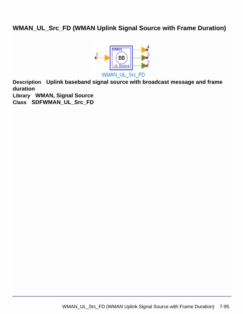
WMAN_UL_Src_FD (WMAN Uplink Signal Source with Frame Duration)
Description Uplink baseband signal source with broadcast message and frame durationLibrary WMAN, Signal SourceClass SDFWMAN_UL_Src_FD
WMAN_UL_Src_FD (WMAN Uplink Signal Source with Frame Duration) 7-95
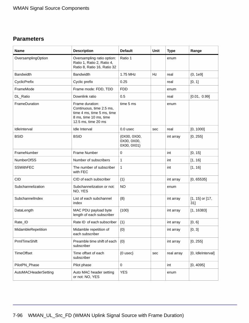
WMAN Signal Source Components
Parameters
Name Description Default Unit Type Range
OversamplingOption Oversampling ratio option: Ratio 1, Ratio 2, Ratio 4, Ratio 8, Ratio 16, Ratio 32
Ratio 1 enum
Bandwidth Bandwidth 1.75 MHz Hz real (0, 1e9]
CyclicPrefix Cyclic prefix 0.25 real [0, 1]
FrameMode Frame mode: FDD, TDD FDD enum
DL_Ratio Downlink ratio 0.5 real [0.01, 0.99]
FrameDuration Frame duration: Continuous, time 2.5 ms, time 4 ms, time 5 ms, time 8 ms, time 10 ms, time 12.5 ms, time 20 ms
time 5 ms enum
IdleInterval Idle Interval 0.0 usec sec real [0, 1000]
BSID BSID {0X00, 0X00, 0X00, 0X00, 0X00, 0X01}
int array [0, 255]
FrameNumber Frame Number 0 int [0, 15]
NumberOfSS Number of subscribers 1 int [1, 16]
SSWithFEC The number of subscriber with FEC
1 int [1, 16]
CID CID of each subscriber {1} int array [0, 65535]
Subchannelization Subchannelization or not: NO, YES
NO enum
SubchannelIndex List of each subchannel index
{8} int array [1, 15] or [17, 31]
DataLength MAC PDU payload byte length of each subscriber
{100} int array [1, 16383]
Rate_ID Rate ID of each subscriber {1} int array [0, 6]
MidambleRepetition Midamble repetition of each subscriber
{0} int array [0, 3]
PrmlTimeShift Preamble time shift of each subscriber
{0} int array [0, 255]
TimeOffset Time offset of each subscriber
{0 usec} sec real array [0, IdleInterval]
PilotPN_Phase Pilot phase 0 int [0, 4095]
AutoMACHeaderSetting Auto MAC header setting or not: NO, YES
YES enum
7-96 WMAN_UL_Src_FD (WMAN Uplink Signal Source with Frame Duration)
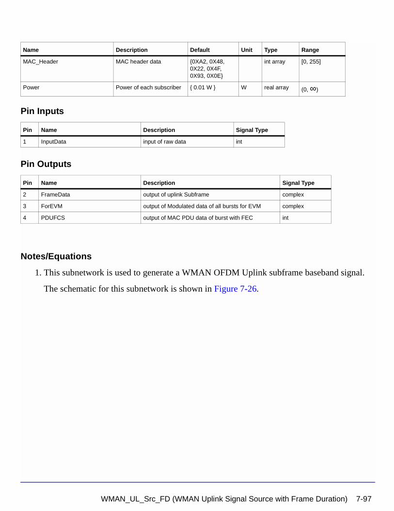
Pin Inputs
Pin Outputs
Notes/Equations
1. This subnetwork is used to generate a WMAN OFDM Uplink subframe baseband signal.
The schematic for this subnetwork is shown in Figure 7-26.
MAC_Header MAC header data {0XA2, 0X48, 0X22, 0X4F, 0X93, 0X0E}
int array [0, 255]
Power Power of each subscriber { 0.01 W } W real array (0, ∞)
Pin Name Description Signal Type
1 InputData input of raw data int
Pin Name Description Signal Type
2 FrameData output of uplink Subframe complex
3 ForEVM output of Modulated data of all bursts for EVM complex
4 PDUFCS output of MAC PDU data of burst with FEC int
Name Description Default Unit Type Range
WMAN_UL_Src_FD (WMAN Uplink Signal Source with Frame Duration) 7-97
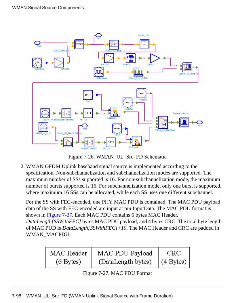
WMAN Signal Source Components
Figure 7-26. WMAN_UL_Src_FD Schematic
2. WMAN OFDM Uplink baseband signal source is implemented according to the specification. Non-subchannelization and subchannelization modes are supported. The maximum number of SSs supported is 16. For non-subchannelization mode, the maximum number of bursts supported is 16. For subchannelization mode, only one burst is supported, where maximum 16 SSs can be allocated, while each SS uses one different subchannel.
For the SS with FEC-encoded, one PHY MAC PDU is contained. The MAC PDU payload data of the SS with FEC-encoded are input at pin InputData. The MAC PDU format is shown in Figure 7-27. Each MAC PDU contains 6 bytes MAC Header, DataLength[SSWithFEC] bytes MAC PDU payload, and 4 bytes CRC. The total byte length of MAC PUD is DataLength[SSWithFEC]+10. The MAC Header and CRC are padded in WMAN_MACPDU.
Figure 7-27. MAC PDU Format
7-98 WMAN_UL_Src_FD (WMAN Uplink Signal Source with Frame Duration)
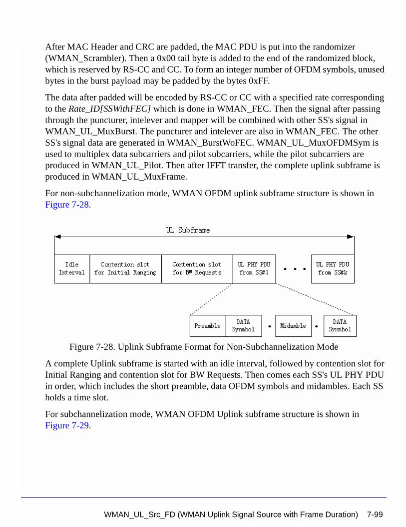
After MAC Header and CRC are padded, the MAC PDU is put into the randomizer (WMAN_Scrambler). Then a 0x00 tail byte is added to the end of the randomized block, which is reserved by RS-CC and CC. To form an integer number of OFDM symbols, unused bytes in the burst payload may be padded by the bytes 0xFF.
The data after padded will be encoded by RS-CC or CC with a specified rate corresponding to the Rate_ID[SSWithFEC] which is done in WMAN_FEC. Then the signal after passing through the puncturer, intelever and mapper will be combined with other SS's signal in WMAN_UL_MuxBurst. The puncturer and intelever are also in WMAN_FEC. The other SS's signal data are generated in WMAN_BurstWoFEC. WMAN_UL_MuxOFDMSym is used to multiplex data subcarriers and pilot subcarriers, while the pilot subcarriers are produced in WMAN_UL_Pilot. Then after IFFT transfer, the complete uplink subframe is produced in WMAN_UL_MuxFrame.
For non-subchannelization mode, WMAN OFDM uplink subframe structure is shown in Figure 7-28.
Figure 7-28. Uplink Subframe Format for Non-Subchannelization Mode
A complete Uplink subframe is started with an idle interval, followed by contention slot for Initial Ranging and contention slot for BW Requests. Then comes each SS's UL PHY PDU in order, which includes the short preamble, data OFDM symbols and midambles. Each SS holds a time slot.
For subchannelization mode, WMAN OFDM Uplink subframe structure is shown in Figure 7-29.
WMAN_UL_Src_FD (WMAN Uplink Signal Source with Frame Duration) 7-99
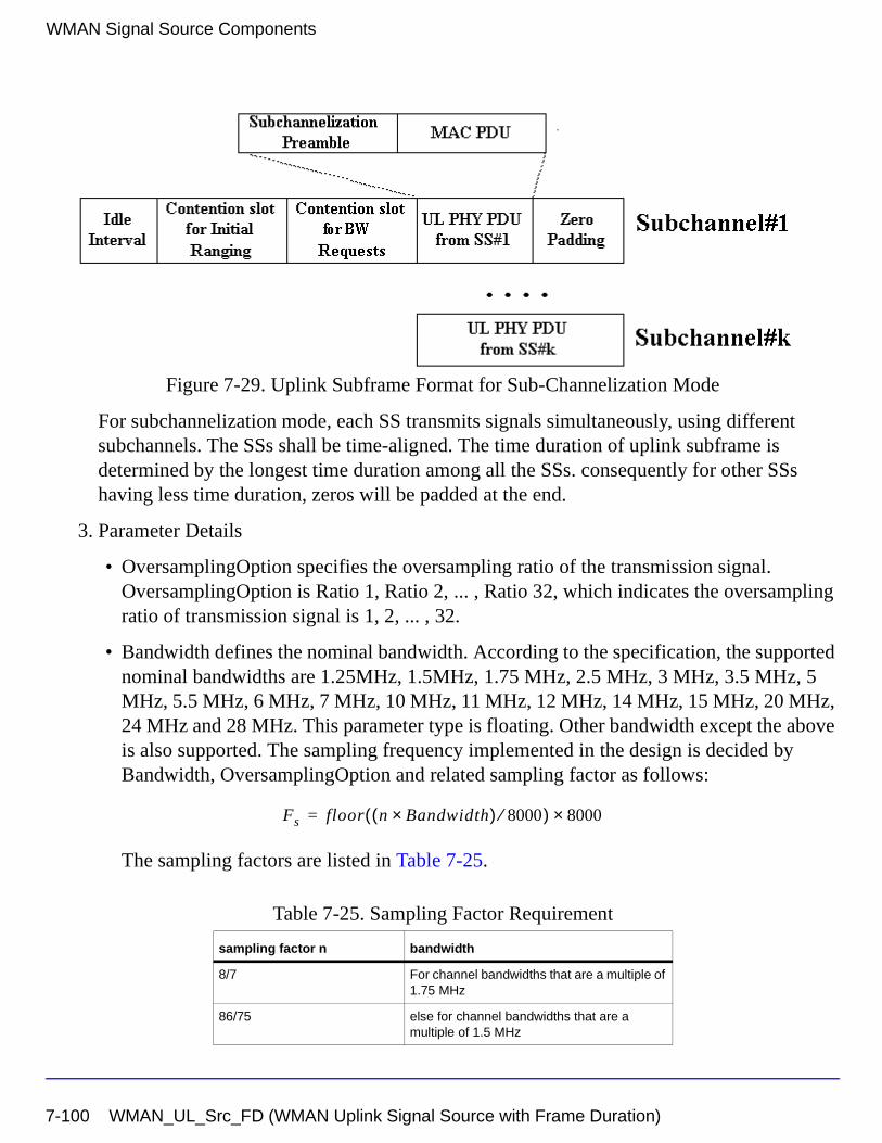
WMAN Signal Source Components
Figure 7-29. Uplink Subframe Format for Sub-Channelization Mode
For subchannelization mode, each SS transmits signals simultaneously, using different subchannels. The SSs shall be time-aligned. The time duration of uplink subframe is determined by the longest time duration among all the SSs. consequently for other SSs having less time duration, zeros will be padded at the end.
3. Parameter Details
• OversamplingOption specifies the oversampling ratio of the transmission signal. OversamplingOption is Ratio 1, Ratio 2, ... , Ratio 32, which indicates the oversampling ratio of transmission signal is 1, 2, ... , 32.
• Bandwidth defines the nominal bandwidth. According to the specification, the supported nominal bandwidths are 1.25MHz, 1.5MHz, 1.75 MHz, 2.5 MHz, 3 MHz, 3.5 MHz, 5 MHz, 5.5 MHz, 6 MHz, 7 MHz, 10 MHz, 11 MHz, 12 MHz, 14 MHz, 15 MHz, 20 MHz, 24 MHz and 28 MHz. This parameter type is floating. Other bandwidth except the above is also supported. The sampling frequency implemented in the design is decided by Bandwidth, OversamplingOption and related sampling factor as follows:
The sampling factors are listed in Table 7-25.
Table 7-25. Sampling Factor Requirement
sampling factor n bandwidth
8/7 For channel bandwidths that are a multiple of 1.75 MHz
86/75 else for channel bandwidths that are a multiple of 1.5 MHz
Fs floor n Bandwidth×( ) 8000⁄( ) 8000×=
7-100 WMAN_UL_Src_FD (WMAN Uplink Signal Source with Frame Duration)
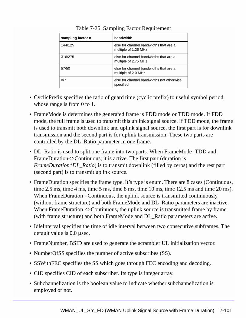
• CyclicPrefix specifies the ratio of guard time (cyclic prefix) to useful symbol period, whose range is from 0 to 1.
• FrameMode is determines the generated frame is FDD mode or TDD mode. If FDD mode, the full frame is used to transmit this uplink signal source. If TDD mode, the frame is used to transmit both downlink and uplink signal source, the first part is for downlink transmission and the second part is for uplink transmission. These two parts are controlled by the DL_Ratio parameter in one frame.
• DL_Ratio is used to split one frame into two parts. When FrameMode=TDD and FrameDuration<>Continuous, it is active. The first part (duration is FrameDuration*DL_Ratio) is to transmit downlink (filled by zeros) and the rest part (second part) is to transmit uplink source.
• FrameDuration specifies the frame type. It’s type is enum. There are 8 cases (Continuous, time 2.5 ms, time 4 ms, time 5 ms, time 8 ms, time 10 ms, time 12.5 ms and time 20 ms). When FrameDuration =Continuous, the uplink source is transmitted continuously (without frame structure) and both FrameMode and DL_Ratio parameters are inactive. When FrameDuration <>Continuous, the uplink source is transmitted frame by frame (with frame structure) and both FrameMode and DL_Ratio parameters are active.
• IdleInterval specifies the time of idle interval between two consecutive subframes. The default value is 0.0 µsec.
• FrameNumber, BSID are used to generate the scrambler UL initialization vector.
• NumberOfSS specifies the number of active subscribes (SS).
• SSWithFEC specifies the SS which goes through FEC encoding and decoding.
• CID specifies CID of each subscriber. Its type is integer array.
• Subchannelization is the boolean value to indicate whether subchannelization is employed or not.
144/125 else for channel bandwidths that are a multiple of 1.25 MHz
316/275 else for channel bandwidths that are a multiple of 2.75 MHz
57/50 else for channel bandwidths that are a multiple of 2.0 MHz
8/7 else for channel bandwidths not otherwise specified
Table 7-25. Sampling Factor Requirement
sampling factor n bandwidth
WMAN_UL_Src_FD (WMAN Uplink Signal Source with Frame Duration) 7-101
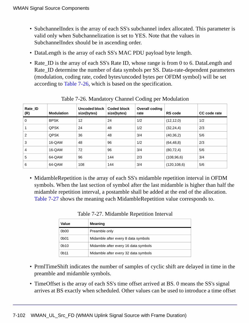
WMAN Signal Source Components
• SubchannelIndex is the array of each SS's subchannel index allocated. This parameter is valid only when Subchannelization is set to YES. Note that the values in SubchannelIndex should be in ascending order.
• DataLength is the array of each SS's MAC PDU payload byte length.
• Rate_ID is the array of each SS's Rate ID, whose range is from 0 to 6. DataLength and Rate_ID determine the number of data symbols per SS. Data-rate-dependent parameters (modulation, coding rate, coded bytes/uncoded bytes per OFDM symbol) will be set according to Table 7-26, which is based on the specification.
• MidambleRepetition is the array of each SS's midamble repetition interval in OFDM symbols. When the last section of symbol after the last midamble is higher than half the midamble repetition interval, a postamble shall be added at the end of the allocation. Table 7-27 shows the meaning each MidambleRepetition value corresponds to.
• PrmlTimeShift indicates the number of samples of cyclic shift are delayed in time in the preamble and midamble symbols.
• TimeOffset is the array of each SS's time offset arrived at BS. 0 means the SS's signal arrives at BS exactly when scheduled. Other values can be used to introduce a time offset
Table 7-26. Mandatory Channel Coding per Modulation
Rate_ID(R) Modulation
Uncoded block size(bytes)
Coded block size(bytes)
Overall coding rate RS code CC code rate
0 BPSK 12 24 1/2 (12,12,0) 1/2
1 QPSK 24 48 1/2 (32,24,4) 2/3
2 QPSK 36 48 3/4 (40,36,2) 5/6
3 16-QAM 48 96 1/2 (64,48,8) 2/3
4 16-QAM 72 96 3/4 (80,72,4) 5/6
5 64-QAM 96 144 2/3 (108,96,6) 3/4
6 64-QAM 108 144 3/4 (120,108,6) 5/6
Table 7-27. Midamble Repetition Interval
Value Meaning
0b00 Preamble only
0b01 Midamble after every 8 data symbols
0b10 Midamble after every 16 data symbols
0b11 Midamble after every 32 data symbols
7-102 WMAN_UL_Src_FD (WMAN Uplink Signal Source with Frame Duration)
to simulate arrival differences between different SS transmissions. Note that the actual time offset delay of each SS is the value in TimeOffset minus the last SS's time offset.
• PilotPN_Phase specifies the start phase of pilots (PRBS). The specification requires PilotPN_Phase = 0.
• AutoMACHeaderSetting specifies how to get the 6 bytes MAC header. If AutoMACHeaderSetting=YES, these 6 bytes MAC header is generated by WMAN_MACHeader directly. If AutoMACHeaderSetting=NO, these 6 bytes MAC header is input by MAC_Header parameter.
• MAC_Header specifies the 6 byte data inserted in MAC Header. It is active just when AutoMACHeaderSetting=NO.
• Power is the array of each SS's transmitting power. In non-subchannelization mode, the first SS's output voltage is adjusted to be 1, by multiplying signal amplitude with Gain, where Gain is defined as:
For other SS, the ith SS's output voltage is adjusted aligned with the first SS's by multiplying signal amplitude with Gain[i] respectively, where Gain[i] is defined as:
Here Power[1] is the first SS's Power.
In subchannelization mode, the first SS's output voltage is adjusted to be 1, while other SSs' output voltages are adjusted according to the ratio of the number of subcarriers the SSs contain to the number of subcarriers the first SS contains. Note that only the first value in the array of Power is used to adjust the first SS's output voltage, and other values in the array of Power are ignored.
4. Output Pin Delay Adjustment
Before introducing delays for each output pins, the number of OFDM symbols per frame is deduced in this section.
The non-subchannelization and subchannelization modes are supported in WMAN OFDM uplink.
For non-subchannelization mode, one WMAN uplink subframe consists of Idle, contention slot for Initial Ranging and contention slot for BW, and multiple uplink bursts. Contention slot for Initial Ranging and contention slot for BW Requests consist of two OFDM symbols respectively. Each uplink burst consists of one short preamble, data symbols and midambles. The short preamble consists of one OFDM symbols.
Gain 256 2OversamplingOption
200( )⁄×=
Gain i[ ] Gain 1[ ] Power i[ ]( ) Power 1[ ]( )⁄×=
WMAN_UL_Src_FD (WMAN Uplink Signal Source with Frame Duration) 7-103
WMAN Signal Source Components
The number of OFDM data symbols of ith uplink SS( ) is calculated as follows:
MidambleRepetition indicates each SS's midamble repetition interval in OFDM symbols. Let represent the number of midamble symbols in ith uplink burst,
if is not zero
else
So the total number of OFDM symbols for the uplink frame is calculated as
follows:
The number of samples per one OFDM symbol ( ) is calculated as:
where, G is the CyclicPrefix.
The samples of IdleInterval( ) is calculated as follows:
When FrameDuration=Continuous, the total samples of one uplink subframe
is
When FrameDuration<>Continuous, the total samples of one uplink subframe
is
NSymbol i[ ]
NSymbol i[ ] ceil DataLength i[ ] 11+( ) uncodedBlockSize R i[ ][ ]( )⁄( )=
Midamble i[ ]
Midamble i[ ] round NSymbol i[ ]( ) 2MidambleRepetition i[ ] 1+⁄( )=
MidambleRepetition i[ ]
Midamble i[ ] 0=
NtotalSymbol
NtotalSymbol 2 2 NSymbol i[ ] 1 Midamble i[ ]+ +( )i 1=
NumberOfSS
∑+ +=
SamplesOFDM
SamplesOFDM 2OversamplingOption
256× 1 G+( )×=
Samplesidle
Samplesidle IdleInterval Fs×=
SamplesFrame
SamplesFrame Samplesidle NtotalSymbol SamplesOFDM×+=
SamplesFrame
SamplesFrame Samplesidle FrameDuration Fs× 2OversamplingOption×+=
7-104 WMAN_UL_Src_FD (WMAN Uplink Signal Source with Frame Duration)
For subchannelization mode, one WMAN uplink subframe consists of Idle, contention slot for Initial Ranging and contention slot for BW, and one uplink burst which contains all SSs.
The number of OFDM data symbols of ith uplink SS( ) is calculated as follows:
Here Nsubchannels is the number of subchannels. Nsubchannels is determined by
SubchannelIndex, shown in Table 7-28.
So the total number of OFDM symbols for the uplink frame is calculated as
follows:
When FrameDuration=Continuous, the total samples of one uplink subframe
is
In the source, delay is introduced by TransmitterFilter in the design WMAN_UL_SignalSrc, where the delay is equal to . Length is the parameter in TransmitterFilter.
References
[1] IEEE Std 802.16-2004, Part 16: Air Interface for Fixed Broadband Wireless Access Systems, Section 8.3 WirelessMAN-OFDM PHY, October 1, 2004.
Table 7-28. Number of Subchannels
Nsubchannels SubchannelIndex
1 1,3,5,7,9,11,13,15,17,19,21,23,25,27,29,31
2 2,6,10,14,18,22,26,30
4 4,12,20,28
8 8,24
NSymbol i[ ]
NSymbol i[ ] ceil DataLength i[ ] 11+( ) uncodedBlockSize R i[ ][ ]( )⁄ 16 Nsubchannels⁄×( )=
NtotalSymbol
NtotalSymbol 2 2 max NSymbol i[ ] 1 Midamble i[ ]+ +( )+ +=
SamplesFrame
SamplesFrame Samplesidle NtotalSymbol SamplesOFDM×+=
30 2oversamplingOption×
Length 1–( ) 2⁄
WMAN_UL_Src_FD (WMAN Uplink Signal Source with Frame Duration) 7-105
WMAN Signal Source Components
[2] IEEE P802.16-2004/Cor1/D5, Corrigendum to IEEE Standard for Local and Metropolitan Area Networks - Part 16: Air Interface for Fixed Broadband Wireless Access Systems, Sept. 2005.
7-106 WMAN_UL_Src_FD (WMAN Uplink Signal Source with Frame Duration)
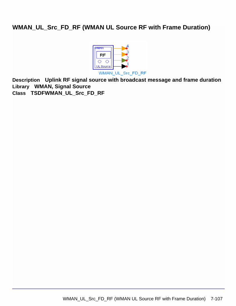
WMAN_UL_Src_FD_RF (WMAN UL Source RF with Frame Duration)
Description Uplink RF signal source with broadcast message and frame durationLibrary WMAN, Signal SourceClass TSDFWMAN_UL_Src_FD_RF
WMAN_UL_Src_FD_RF (WMAN UL Source RF with Frame Duration) 7-107
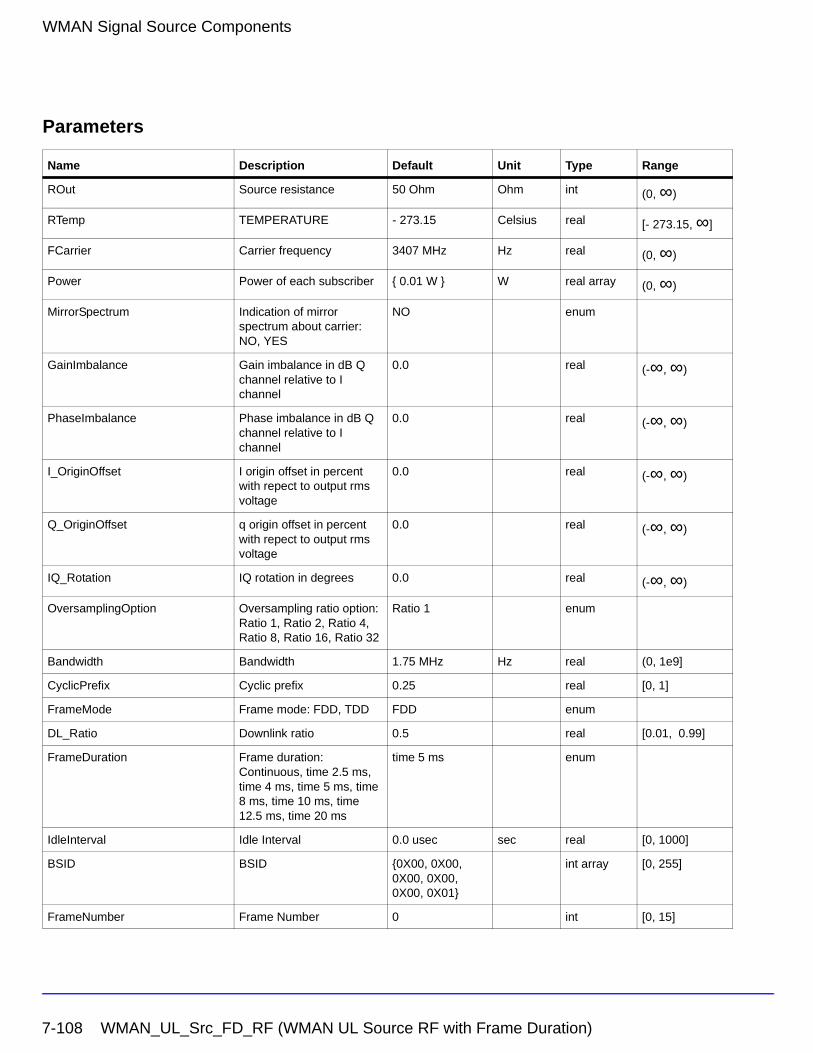
WMAN Signal Source Components
Parameters
Name Description Default Unit Type Range
ROut Source resistance 50 Ohm Ohm int (0, ∞)
RTemp TEMPERATURE - 273.15 Celsius real [- 273.15, ∞]
FCarrier Carrier frequency 3407 MHz Hz real (0, ∞)
Power Power of each subscriber { 0.01 W } W real array (0, ∞)
MirrorSpectrum Indication of mirror spectrum about carrier: NO, YES
NO enum
GainImbalance Gain imbalance in dB Q channel relative to I channel
0.0 real (-∞, ∞)
PhaseImbalance Phase imbalance in dB Q channel relative to I channel
0.0 real (-∞, ∞)
I_OriginOffset I origin offset in percent with repect to output rms voltage
0.0 real (-∞, ∞)
Q_OriginOffset q origin offset in percent with repect to output rms voltage
0.0 real (-∞, ∞)
IQ_Rotation IQ rotation in degrees 0.0 real (-∞, ∞)
OversamplingOption Oversampling ratio option: Ratio 1, Ratio 2, Ratio 4, Ratio 8, Ratio 16, Ratio 32
Ratio 1 enum
Bandwidth Bandwidth 1.75 MHz Hz real (0, 1e9]
CyclicPrefix Cyclic prefix 0.25 real [0, 1]
FrameMode Frame mode: FDD, TDD FDD enum
DL_Ratio Downlink ratio 0.5 real [0.01, 0.99]
FrameDuration Frame duration: Continuous, time 2.5 ms, time 4 ms, time 5 ms, time 8 ms, time 10 ms, time 12.5 ms, time 20 ms
time 5 ms enum
IdleInterval Idle Interval 0.0 usec sec real [0, 1000]
BSID BSID {0X00, 0X00, 0X00, 0X00, 0X00, 0X01}
int array [0, 255]
FrameNumber Frame Number 0 int [0, 15]
7-108 WMAN_UL_Src_FD_RF (WMAN UL Source RF with Frame Duration)
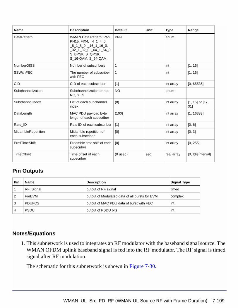
Pin Outputs
Notes/Equations
1. This subnetwork is used to integrates an RF modulator with the baseband signal source. The WMAN OFDM uplink baseband signal is fed into the RF modulator. The RF signal is timed signal after RF modulation.
The schematic for this subnetwork is shown in Figure 7-30.
DataPattern WMAN Data Pattern: PN9, PN15, FIX4, _4_1_4_0, _8_1_8_0, _16_1_16_0, _32_1_32_0, _64_1_64_0, S_BPSK, S_QPSK, S_16-QAM, S_64-QAM
PN9 enum
NumberOfSS Number of subscribers 1 int [1, 16]
SSWithFEC The number of subscriber with FEC
1 int [1, 16]
CID CID of each subscriber {1} int array [0, 65535]
Subchannelization Subchannelization or not: NO, YES
NO enum
SubchannelIndex List of each subchannel index
{8} int array [1, 15] or [17, 31]
DataLength MAC PDU payload byte length of each subscriber
{100} int array [1, 16383]
Rate_ID Rate ID of each subscriber {1} int array [0, 6]
MidambleRepetition Midamble repetition of each subscriber
{0} int array [0, 3]
PrmlTimeShift Preamble time shift of each subscriber
{0} int array [0, 255]
TimeOffset Time offset of each subscriber
{0 usec} sec real array [0, IdleInterval]
Pin Name Description Signal Type
1 RF_Signal output of RF signal timed
2 ForEVM output of Modulated data of all bursts for EVM complex
3 PDUFCS output of MAC PDU data of burst with FEC int
4 PSDU output of PSDU bits int
Name Description Default Unit Type Range
WMAN_UL_Src_FD_RF (WMAN UL Source RF with Frame Duration) 7-109
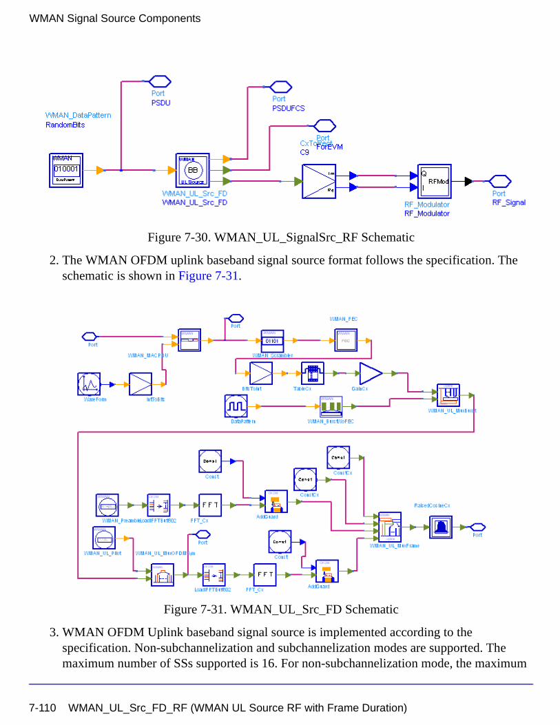
WMAN Signal Source Components
Figure 7-30. WMAN_UL_SignalSrc_RF Schematic
2. The WMAN OFDM uplink baseband signal source format follows the specification. The schematic is shown in Figure 7-31.
Figure 7-31. WMAN_UL_Src_FD Schematic
3. WMAN OFDM Uplink baseband signal source is implemented according to the specification. Non-subchannelization and subchannelization modes are supported. The maximum number of SSs supported is 16. For non-subchannelization mode, the maximum
7-110 WMAN_UL_Src_FD_RF (WMAN UL Source RF with Frame Duration)
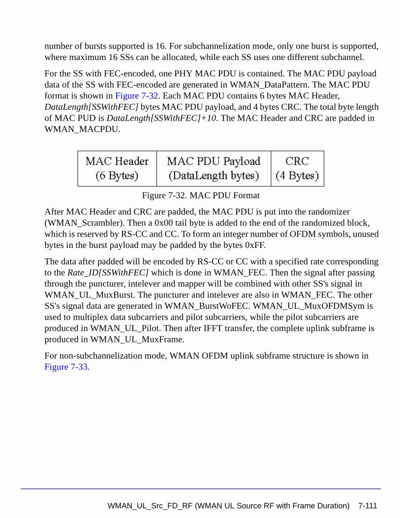
number of bursts supported is 16. For subchannelization mode, only one burst is supported, where maximum 16 SSs can be allocated, while each SS uses one different subchannel.
For the SS with FEC-encoded, one PHY MAC PDU is contained. The MAC PDU payload data of the SS with FEC-encoded are generated in WMAN_DataPattern. The MAC PDU format is shown in Figure 7-32. Each MAC PDU contains 6 bytes MAC Header, DataLength[SSWithFEC] bytes MAC PDU payload, and 4 bytes CRC. The total byte length of MAC PUD is DataLength[SSWithFEC]+10. The MAC Header and CRC are padded in WMAN_MACPDU.
Figure 7-32. MAC PDU Format
After MAC Header and CRC are padded, the MAC PDU is put into the randomizer (WMAN_Scrambler). Then a 0x00 tail byte is added to the end of the randomized block, which is reserved by RS-CC and CC. To form an integer number of OFDM symbols, unused bytes in the burst payload may be padded by the bytes 0xFF.
The data after padded will be encoded by RS-CC or CC with a specified rate corresponding to the Rate_ID[SSWithFEC] which is done in WMAN_FEC. Then the signal after passing through the puncturer, intelever and mapper will be combined with other SS's signal in WMAN_UL_MuxBurst. The puncturer and intelever are also in WMAN_FEC. The other SS's signal data are generated in WMAN_BurstWoFEC. WMAN_UL_MuxOFDMSym is used to multiplex data subcarriers and pilot subcarriers, while the pilot subcarriers are produced in WMAN_UL_Pilot. Then after IFFT transfer, the complete uplink subframe is produced in WMAN_UL_MuxFrame.
For non-subchannelization mode, WMAN OFDM uplink subframe structure is shown in Figure 7-33.
WMAN_UL_Src_FD_RF (WMAN UL Source RF with Frame Duration) 7-111
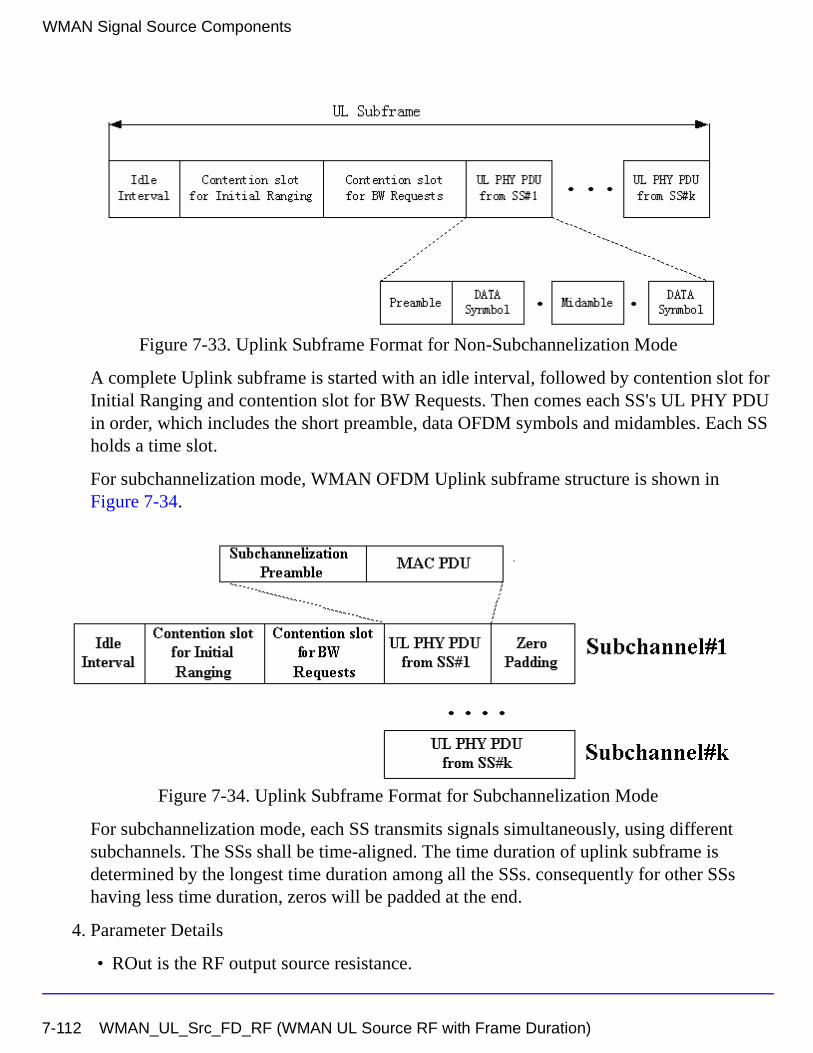
WMAN Signal Source Components
Figure 7-33. Uplink Subframe Format for Non-Subchannelization Mode
A complete Uplink subframe is started with an idle interval, followed by contention slot for Initial Ranging and contention slot for BW Requests. Then comes each SS's UL PHY PDU in order, which includes the short preamble, data OFDM symbols and midambles. Each SS holds a time slot.
For subchannelization mode, WMAN OFDM Uplink subframe structure is shown in Figure 7-34.
Figure 7-34. Uplink Subframe Format for Subchannelization Mode
For subchannelization mode, each SS transmits signals simultaneously, using different subchannels. The SSs shall be time-aligned. The time duration of uplink subframe is determined by the longest time duration among all the SSs. consequently for other SSs having less time duration, zeros will be padded at the end.
4. Parameter Details
• ROut is the RF output source resistance.
7-112 WMAN_UL_Src_FD_RF (WMAN UL Source RF with Frame Duration)
• RTemp is the RF output source resistance temperature in Celsius and sets the noise density in the RF output signal to (k(RTemp+273.15)) Watts/Hz, where k is Boltzmann's constant.
• FCarrier is the RF output signal frequency.
• Power is the array of each SS‘s RF output signal power. The Power of the signal is defined as the average SS‘s power excluding the idle interval time intervals.
• MirrorSpectrum is used to mirror the RF_out signal spectrum about the carrier. This is equivalent to conjugating the complex RF envelope voltage. Depending on the configuration and number of mixers in an RF transmitter, the RF output signal from hardware RF generators can be inverted. If such an RF signal is desired, set this parameter to YES.
• GainImbalance, PhaseImbalance, I_OriginOffset, Q_OriginOffset, and IQ_Rotation are used to add certain impairments to the ideal output RF signal. Impairments are added in the order described here.
The unimpaired RF I and Q envelope voltages have gain and phase imbalance applied. The RF is given by:
where A is a scaling factor based on the Power and ROut parameters specified by the user, VI(t) is the in-phase RF envelope, VQ(t) is the quadrature phase RF envelope, g is
the gain imbalance:
and, (in degrees) is the phase imbalance.
Next, the signal VRF(t) is rotated by IQ_Rotation degrees. The I_OriginOffset and
Q_OriginOffset are then applied to the rotated signal. Note that the amounts specified are percentages with respect to the output rms voltage. The output rms voltage is given by sqrt(2×ROut×Power).
• OversamplingOption specifies the oversampling ratio of the transmission signal. OversamplingOption is Ratio 1, Ratio 2, ... , Ratio 32, which indicates the oversampling ratio of transmission signal is 1, 2, ... , 32.
• Bandwidth defines the nominal bandwidth. According to the specification, the supported nominal bandwidths are 1.25MHz, 1.5MHz, 1.75 MHz, 2.5 MHz, 3 MHz, 3.5 MHz, 5
VRF t( ) A VI t( ) ωct( )cos gVQ t( ) ωctΦπ180---------+
sin– =
g 10
GainImbalance20
-----------------------------------------
=
φ
WMAN_UL_Src_FD_RF (WMAN UL Source RF with Frame Duration) 7-113
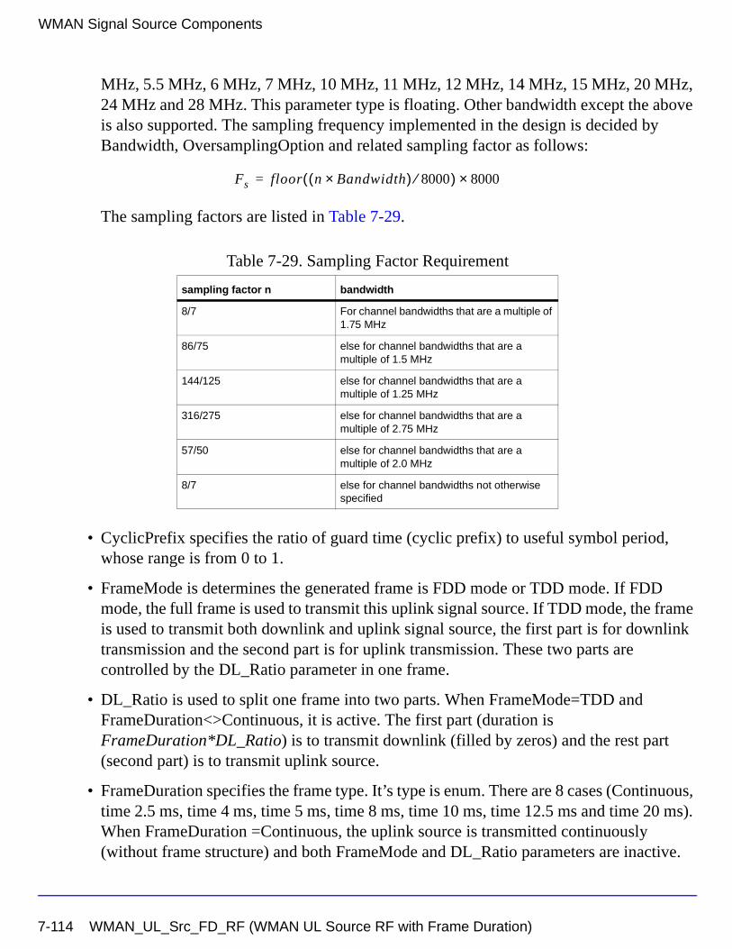
WMAN Signal Source Components
MHz, 5.5 MHz, 6 MHz, 7 MHz, 10 MHz, 11 MHz, 12 MHz, 14 MHz, 15 MHz, 20 MHz, 24 MHz and 28 MHz. This parameter type is floating. Other bandwidth except the above is also supported. The sampling frequency implemented in the design is decided by Bandwidth, OversamplingOption and related sampling factor as follows:
The sampling factors are listed in Table 7-29.
• CyclicPrefix specifies the ratio of guard time (cyclic prefix) to useful symbol period, whose range is from 0 to 1.
• FrameMode is determines the generated frame is FDD mode or TDD mode. If FDD mode, the full frame is used to transmit this uplink signal source. If TDD mode, the frame is used to transmit both downlink and uplink signal source, the first part is for downlink transmission and the second part is for uplink transmission. These two parts are controlled by the DL_Ratio parameter in one frame.
• DL_Ratio is used to split one frame into two parts. When FrameMode=TDD and FrameDuration<>Continuous, it is active. The first part (duration is FrameDuration*DL_Ratio) is to transmit downlink (filled by zeros) and the rest part (second part) is to transmit uplink source.
• FrameDuration specifies the frame type. It’s type is enum. There are 8 cases (Continuous, time 2.5 ms, time 4 ms, time 5 ms, time 8 ms, time 10 ms, time 12.5 ms and time 20 ms). When FrameDuration =Continuous, the uplink source is transmitted continuously (without frame structure) and both FrameMode and DL_Ratio parameters are inactive.
Table 7-29. Sampling Factor Requirement
sampling factor n bandwidth
8/7 For channel bandwidths that are a multiple of 1.75 MHz
86/75 else for channel bandwidths that are a multiple of 1.5 MHz
144/125 else for channel bandwidths that are a multiple of 1.25 MHz
316/275 else for channel bandwidths that are a multiple of 2.75 MHz
57/50 else for channel bandwidths that are a multiple of 2.0 MHz
8/7 else for channel bandwidths not otherwise specified
Fs floor n Bandwidth×( ) 8000⁄( ) 8000×=
7-114 WMAN_UL_Src_FD_RF (WMAN UL Source RF with Frame Duration)
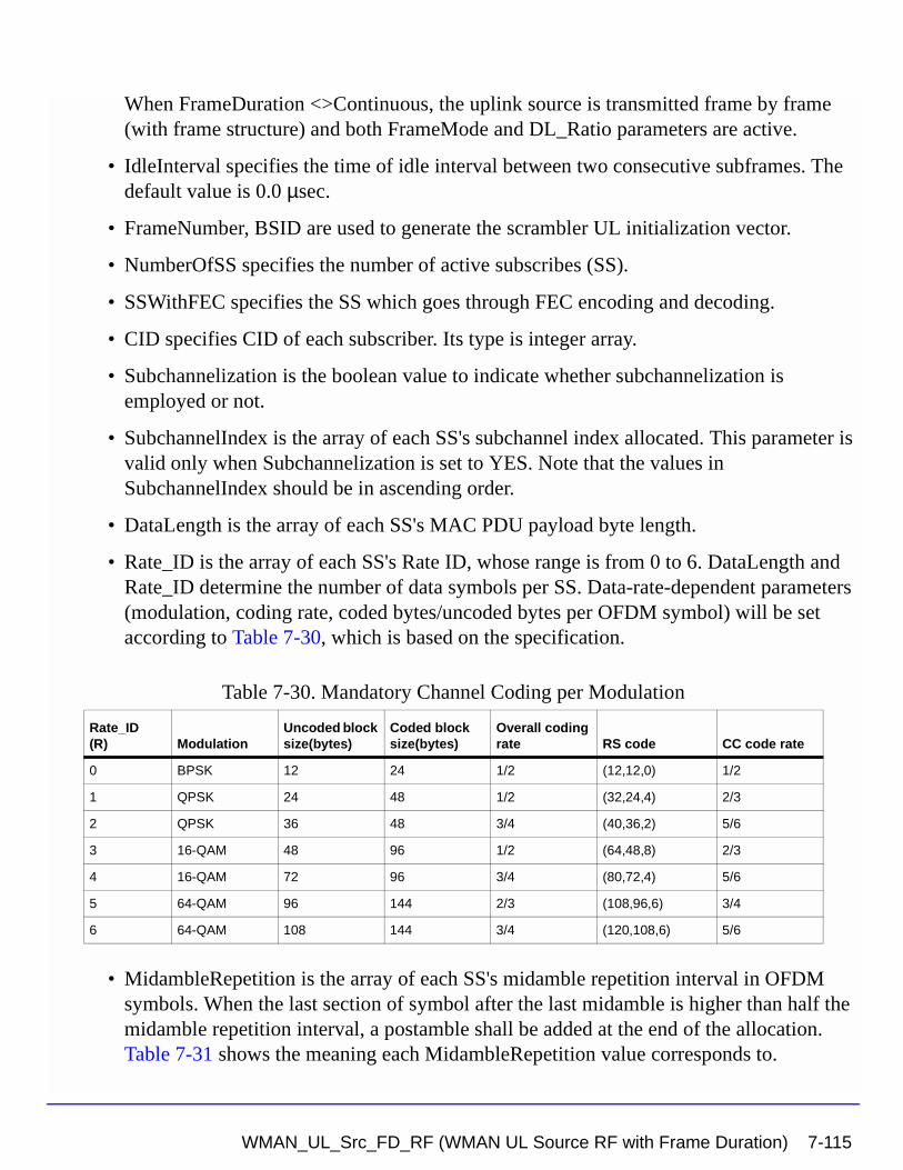
When FrameDuration <>Continuous, the uplink source is transmitted frame by frame (with frame structure) and both FrameMode and DL_Ratio parameters are active.
• IdleInterval specifies the time of idle interval between two consecutive subframes. The default value is 0.0 µsec.
• FrameNumber, BSID are used to generate the scrambler UL initialization vector.
• NumberOfSS specifies the number of active subscribes (SS).
• SSWithFEC specifies the SS which goes through FEC encoding and decoding.
• CID specifies CID of each subscriber. Its type is integer array.
• Subchannelization is the boolean value to indicate whether subchannelization is employed or not.
• SubchannelIndex is the array of each SS's subchannel index allocated. This parameter is valid only when Subchannelization is set to YES. Note that the values in SubchannelIndex should be in ascending order.
• DataLength is the array of each SS's MAC PDU payload byte length.
• Rate_ID is the array of each SS's Rate ID, whose range is from 0 to 6. DataLength and Rate_ID determine the number of data symbols per SS. Data-rate-dependent parameters (modulation, coding rate, coded bytes/uncoded bytes per OFDM symbol) will be set according to Table 7-30, which is based on the specification.
• MidambleRepetition is the array of each SS's midamble repetition interval in OFDM symbols. When the last section of symbol after the last midamble is higher than half the midamble repetition interval, a postamble shall be added at the end of the allocation. Table 7-31 shows the meaning each MidambleRepetition value corresponds to.
Table 7-30. Mandatory Channel Coding per Modulation
Rate_ID(R) Modulation
Uncoded block size(bytes)
Coded block size(bytes)
Overall coding rate RS code CC code rate
0 BPSK 12 24 1/2 (12,12,0) 1/2
1 QPSK 24 48 1/2 (32,24,4) 2/3
2 QPSK 36 48 3/4 (40,36,2) 5/6
3 16-QAM 48 96 1/2 (64,48,8) 2/3
4 16-QAM 72 96 3/4 (80,72,4) 5/6
5 64-QAM 96 144 2/3 (108,96,6) 3/4
6 64-QAM 108 144 3/4 (120,108,6) 5/6
WMAN_UL_Src_FD_RF (WMAN UL Source RF with Frame Duration) 7-115
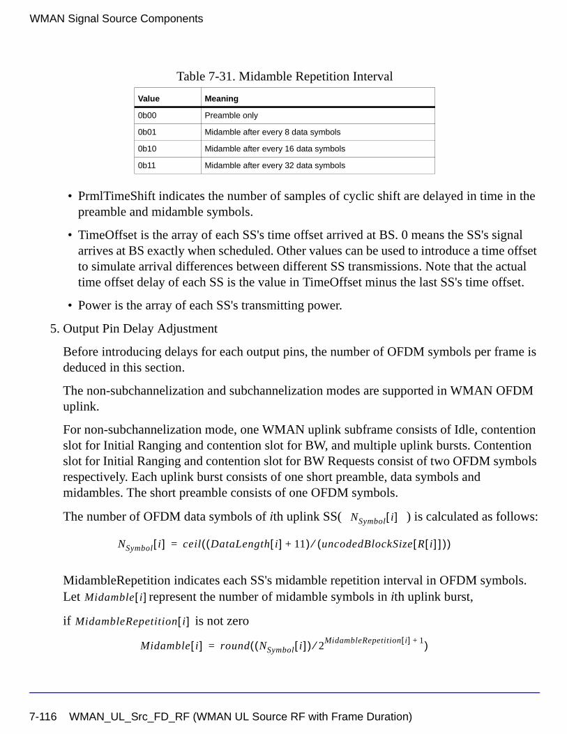
WMAN Signal Source Components
• PrmlTimeShift indicates the number of samples of cyclic shift are delayed in time in the preamble and midamble symbols.
• TimeOffset is the array of each SS's time offset arrived at BS. 0 means the SS's signal arrives at BS exactly when scheduled. Other values can be used to introduce a time offset to simulate arrival differences between different SS transmissions. Note that the actual time offset delay of each SS is the value in TimeOffset minus the last SS's time offset.
• Power is the array of each SS's transmitting power.
5. Output Pin Delay Adjustment
Before introducing delays for each output pins, the number of OFDM symbols per frame is deduced in this section.
The non-subchannelization and subchannelization modes are supported in WMAN OFDM uplink.
For non-subchannelization mode, one WMAN uplink subframe consists of Idle, contention slot for Initial Ranging and contention slot for BW, and multiple uplink bursts. Contention slot for Initial Ranging and contention slot for BW Requests consist of two OFDM symbols respectively. Each uplink burst consists of one short preamble, data symbols and midambles. The short preamble consists of one OFDM symbols.
The number of OFDM data symbols of ith uplink SS( ) is calculated as follows:
MidambleRepetition indicates each SS's midamble repetition interval in OFDM symbols. Let represent the number of midamble symbols in ith uplink burst,
if is not zero
Table 7-31. Midamble Repetition Interval
Value Meaning
0b00 Preamble only
0b01 Midamble after every 8 data symbols
0b10 Midamble after every 16 data symbols
0b11 Midamble after every 32 data symbols
NSymbol i[ ]
NSymbol i[ ] ceil DataLength i[ ] 11+( ) uncodedBlockSize R i[ ][ ]( )⁄( )=
Midamble i[ ]
MidambleRepetition i[ ]
Midamble i[ ] round NSymbol i[ ]( ) 2MidambleRepetition i[ ] 1+⁄( )=
7-116 WMAN_UL_Src_FD_RF (WMAN UL Source RF with Frame Duration)
else
So the total number of OFDM symbols for the uplink frame is calculated as
follows:
The number of samples per one OFDM symbol ( ) is calculated as:
where, G is the CyclicPrefix.
The samples of IdleInterval( ) is calculated as follows:
When FrameDuration=Continuous, the total samples of one uplink subframe
is
When FrameDuration<>Continuous, the total samples of one uplink subframe
is
For subchannelization mode, one WMAN uplink subframe consists of Idle, contention slot for Initial Ranging and contention slot for BW, and one uplink burst which contains all SSs.
The number of OFDM data symbols of ith uplink SS( ) is calculated as follows:
Here Nsubchannels is the number of subchannels. Nsubchannels is determined by
SubchannelIndex, shown in Table 7-32.
Midamble i[ ] 0=
NtotalSymbol
NtotalSymbol 2 2 NSymbol i[ ] 1 Midamble i[ ]+ +( )i 1=
NumberOfSS
∑+ +=
SamplesOFDM
SamplesOFDM 2OversamplingOption
256× 1 G+( )×=
Samplesidle
Samplesidle IdleInterval Fs×=
SamplesFrame
SamplesFrame Samplesidle NtotalSymbol SamplesOFDM×+=
SamplesFrame
SamplesFrame Samplesidle FrameDuration Fs× 2OversamplingOption×+=
NSymbol i[ ]
NSymbol i[ ] ceil DataLength i[ ] 11+( ) uncodedBlockSize R i[ ][ ]( )⁄ 16 Nsubchannels⁄×( )=
WMAN_UL_Src_FD_RF (WMAN UL Source RF with Frame Duration) 7-117
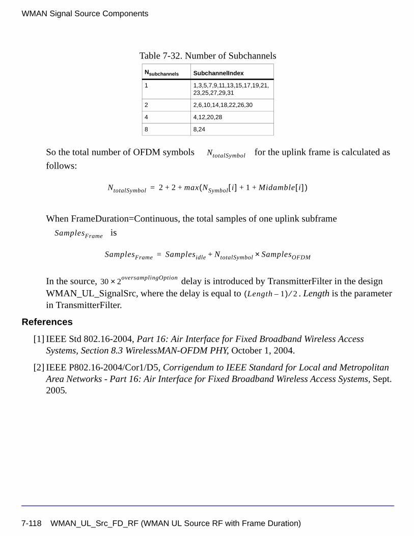
WMAN Signal Source Components
So the total number of OFDM symbols for the uplink frame is calculated as
follows:
When FrameDuration=Continuous, the total samples of one uplink subframe
is
In the source, delay is introduced by TransmitterFilter in the design WMAN_UL_SignalSrc, where the delay is equal to . Length is the parameter in TransmitterFilter.
References
[1] IEEE Std 802.16-2004, Part 16: Air Interface for Fixed Broadband Wireless Access Systems, Section 8.3 WirelessMAN-OFDM PHY, October 1, 2004.
[2] IEEE P802.16-2004/Cor1/D5, Corrigendum to IEEE Standard for Local and Metropolitan Area Networks - Part 16: Air Interface for Fixed Broadband Wireless Access Systems, Sept. 2005.
Table 7-32. Number of Subchannels
Nsubchannels SubchannelIndex
1 1,3,5,7,9,11,13,15,17,19,21,23,25,27,29,31
2 2,6,10,14,18,22,26,30
4 4,12,20,28
8 8,24
NtotalSymbol
NtotalSymbol 2 2 max NSymbol i[ ] 1 Midamble i[ ]+ +( )+ +=
SamplesFrame
SamplesFrame Samplesidle NtotalSymbol SamplesOFDM×+=
30 2oversamplingOption×
Length 1–( ) 2⁄
7-118 WMAN_UL_Src_FD_RF (WMAN UL Source RF with Frame Duration)
Chapter 8: WMAN Design ExamplesThis chapter includes the WMAN OFDM transmitter, receiver, and frame duration design examples.
WMAN OFDM Transmitter Design ExamplesThe WMAN_OFDM_Tx project shows WMAN OFDM transmitter measurement characteristics including EVM, Spectrum flatness, Waveform and CCDF.
Designs for these measurements include:
• WMAN_OFDM_DL_TxEVM.dsn
• WMAN_OFDM_DL_TxSpecFlat.dsn
• WMAN_OFDM_DL_TxWaveform.dsn
• WMAN_OFDM_UL_TxEVM.dsn
Variables used in these designs are listed in Table 8-1.
Downlink Transmitter Error Vector Magnitude Measurement
WMAN_OFDM_DL_TxEVM.dsn
Features
• Support the EVM measurement for each data rate
• Support EVM measurement and constellation output
Table 8-1. VAR Parameters
Parameter Name Description Default Value
FCarrier RF frequency 3407 (MHz)
Bandwidth Nominal bandwidth 1.75 (MHz)
Power Signal power 0.01W
FFTSize FFT size 256
CyclicPrefix Cyclic prefix 1/4
OversamplingOption Oversampling Option Ratio 1
WMAN OFDM Transmitter Design Examples 8-1
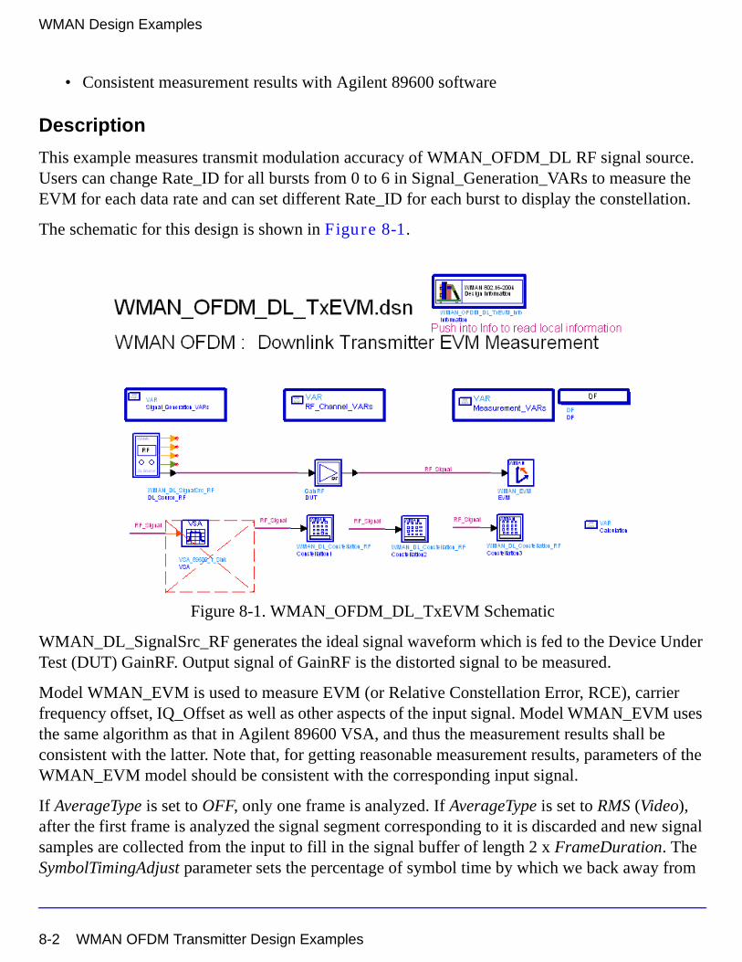
WMAN Design Examples
• Consistent measurement results with Agilent 89600 software
Description
This example measures transmit modulation accuracy of WMAN_OFDM_DL RF signal source. Users can change Rate_ID for all bursts from 0 to 6 in Signal_Generation_VARs to measure the EVM for each data rate and can set different Rate_ID for each burst to display the constellation.
The schematic for this design is shown in Figure 8-1.
Figure 8-1. WMAN_OFDM_DL_TxEVM Schematic
WMAN_DL_SignalSrc_RF generates the ideal signal waveform which is fed to the Device Under Test (DUT) GainRF. Output signal of GainRF is the distorted signal to be measured.
Model WMAN_EVM is used to measure EVM (or Relative Constellation Error, RCE), carrier frequency offset, IQ_Offset as well as other aspects of the input signal. Model WMAN_EVM uses the same algorithm as that in Agilent 89600 VSA, and thus the measurement results shall be consistent with the latter. Note that, for getting reasonable measurement results, parameters of the WMAN_EVM model should be consistent with the corresponding input signal.
If AverageType is set to OFF, only one frame is analyzed. If AverageType is set to RMS (Video), after the first frame is analyzed the signal segment corresponding to it is discarded and new signal samples are collected from the input to fill in the signal buffer of length 2 x FrameDuration. The SymbolTimingAdjust parameter sets the percentage of symbol time by which we back away from
8-2 WMAN OFDM Transmitter Design Examples
the symbol end before we perform the FFT. The TrackAmplitude, TrackPhase, TrackTiming, and EqualizerTraining parameters determine the EVM measurement result. For more information, refer to WMAN_EVM.
Models Constellation1, 2, 3 are used to display the constellation of the first 3 bursts.
Simulation Results
Table 8-2. Key Parameter Setting
Simulation results in the Data Display System are shown in Figure 8-2, which includes the average EVM (or RCE) measurement result in dB and percentage and the constellation of the first 3 bursts.
The relative constellation RMS error, averaged over subcarriers, OFDM frames, and packets, shall not exceed a burst profile dependent value according to Table 8-3 as defined in section 8.3.10.1.2, IEEE Std 802.16-2004.
Table 8-3. Allowed relative constellation error versus data rate
Parameter Value
Signal Power 10 (dBm)
Bandwidth 14 MHz
Oversampling Option Ratio 1
Gain 10 (in dB)
NumberOfBurst 3
Rate_ID {16-QAM-1/2, 16-QAM-1/2, 16-QAM-1/2}
Burst type Relative Constellation Error (dB)
BPSK-1/2 -13.0
QPSK-1/2 -16.0
QPSK-3/4 -18.5
16-QAM-1/2 -21.5
16-QAM-3/4 -25.0
64-QAM-2/3 -28.5
64-QAM-3/4 -31.0
WMAN OFDM Transmitter Design Examples 8-3
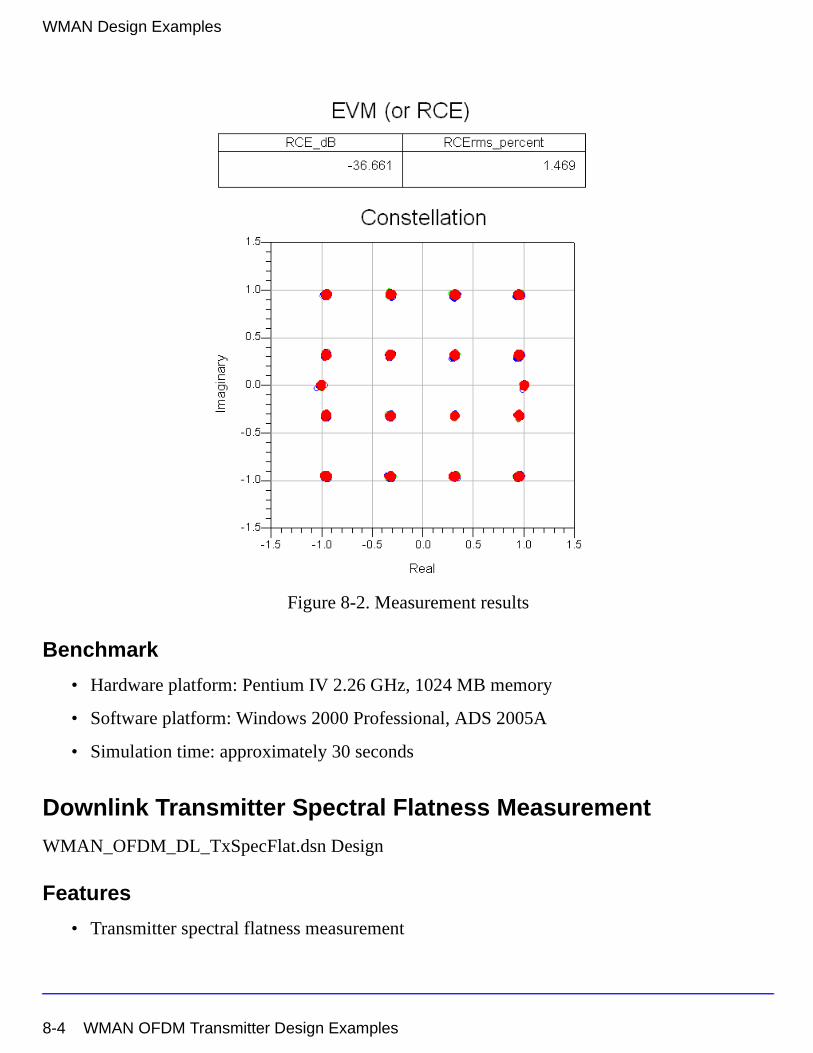
WMAN Design Examples
Figure 8-2. Measurement results
Benchmark
• Hardware platform: Pentium IV 2.26 GHz, 1024 MB memory
• Software platform: Windows 2000 Professional, ADS 2005A
• Simulation time: approximately 30 seconds
Downlink Transmitter Spectral Flatness Measurement
WMAN_OFDM_DL_TxSpecFlat.dsn Design
Features
• Transmitter spectral flatness measurement
8-4 WMAN OFDM Transmitter Design Examples
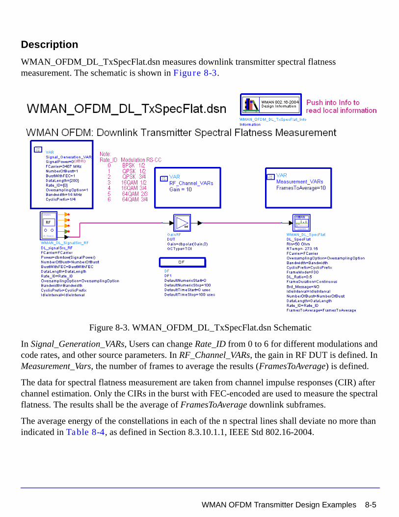
Description
WMAN_OFDM_DL_TxSpecFlat.dsn measures downlink transmitter spectral flatness measurement. The schematic is shown in Figure 8-3.
Figure 8-3. WMAN_OFDM_DL_TxSpecFlat.dsn Schematic
In Signal_Generation_VARs, Users can change Rate_ID from 0 to 6 for different modulations and code rates, and other source parameters. In RF_Channel_VARs, the gain in RF DUT is defined. In Measurement_Vars, the number of frames to average the results (FramesToAverage) is defined.
The data for spectral flatness measurement are taken from channel impulse responses (CIR) after channel estimation. Only the CIRs in the burst with FEC-encoded are used to measure the spectral flatness. The results shall be the average of FramesToAverage downlink subframes.
The average energy of the constellations in each of the n spectral lines shall deviate no more than indicated in Table 8-4, as defined in Section 8.3.10.1.1, IEEE Std 802.16-2004.
WMAN OFDM Transmitter Design Examples 8-5
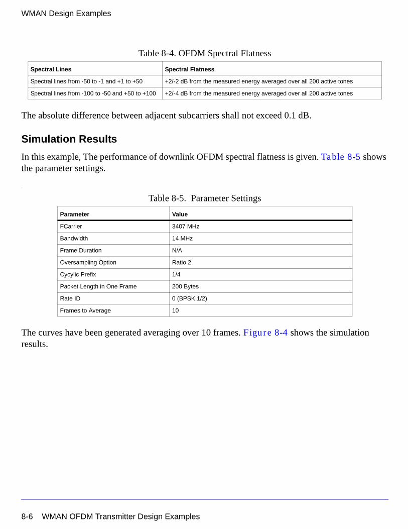
WMAN Design Examples
The absolute difference between adjacent subcarriers shall not exceed 0.1 dB.
Simulation Results
In this example, The performance of downlink OFDM spectral flatness is given. Table 8-5 shows the parameter settings.
.
The curves have been generated averaging over 10 frames. Figure 8-4 shows the simulation results.
Table 8-4. OFDM Spectral Flatness
Spectral Lines Spectral Flatness
Spectral lines from -50 to -1 and +1 to +50 +2/-2 dB from the measured energy averaged over all 200 active tones
Spectral lines from -100 to -50 and +50 to +100 +2/-4 dB from the measured energy averaged over all 200 active tones
Table 8-5. Parameter Settings
Parameter Value
FCarrier 3407 MHz
Bandwidth 14 MHz
Frame Duration N/A
Oversampling Option Ratio 2
Cycylic Prefix 1/4
Packet Length in One Frame 200 Bytes
Rate ID 0 (BPSK 1/2)
Frames to Average 10
8-6 WMAN OFDM Transmitter Design Examples
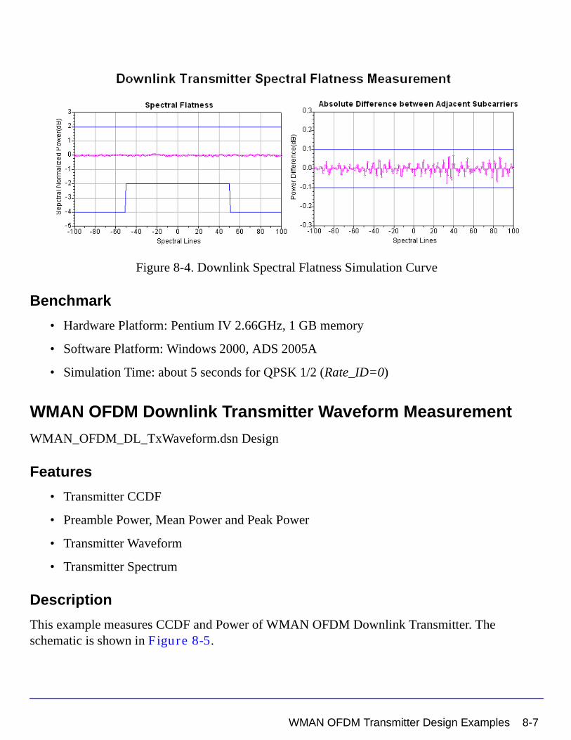
Figure 8-4. Downlink Spectral Flatness Simulation Curve
Benchmark
• Hardware Platform: Pentium IV 2.66GHz, 1 GB memory
• Software Platform: Windows 2000, ADS 2005A
• Simulation Time: about 5 seconds for QPSK 1/2 (Rate_ID=0)
WMAN OFDM Downlink Transmitter Waveform Measurement
WMAN_OFDM_DL_TxWaveform.dsn Design
Features
• Transmitter CCDF
• Preamble Power, Mean Power and Peak Power
• Transmitter Waveform
• Transmitter Spectrum
Description
This example measures CCDF and Power of WMAN OFDM Downlink Transmitter. The schematic is shown in Figure 8-5.
WMAN OFDM Transmitter Design Examples 8-7
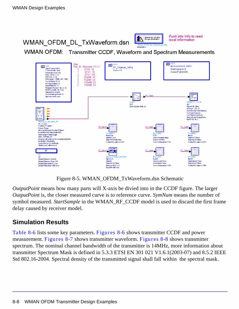
WMAN Design Examples
Figure 8-5. WMAN_OFDM_TxWaveform.dsn Schematic
OutputPoint means how many parts will X-axis be divied into in the CCDF figure. The larger OutputPoint is, the closer measured curve is to reference curve. SymNum means the number of symbol measured. StartSample in the WMAN_RF_CCDF model is used to discard the first frame delay caused by receiver model.
Simulation Results
Table 8-6 lists some key parameters. Figures 8-6 shows transmitter CCDF and power measurement. Figures 8-7 shows transmitter waveform. Figures 8-8 shows transmitter spectrum. The nominal channel bandwidth of the transmitter is 14MHz, more information about transmitter Spectrum Mask is defined in 5.3.3 ETSI EN 301 021 V1.6.1(2003-07) and 8.5.2 IEEE Std 802.16-2004. Spectral density of the transmitted signal shall fall within the spectral mask.
8-8 WMAN OFDM Transmitter Design Examples
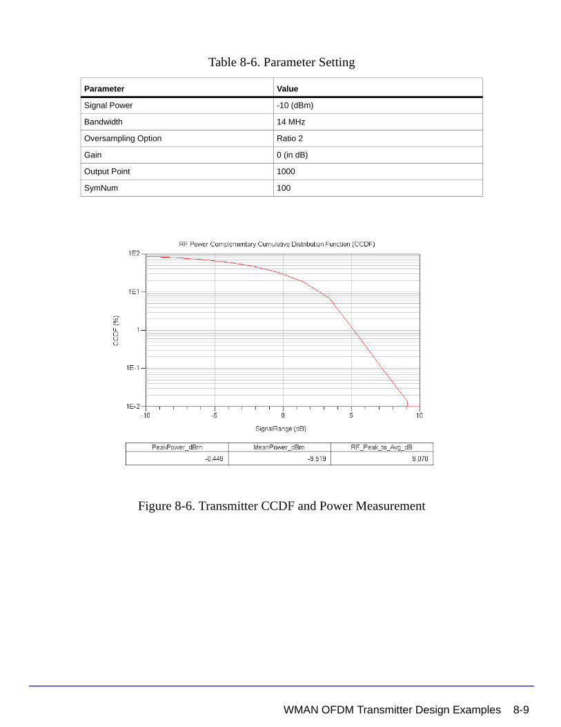
Table 8-6. Parameter Setting
Figure 8-6. Transmitter CCDF and Power Measurement
Parameter Value
Signal Power -10 (dBm)
Bandwidth 14 MHz
Oversampling Option Ratio 2
Gain 0 (in dB)
Output Point 1000
SymNum 100
WMAN OFDM Transmitter Design Examples 8-9
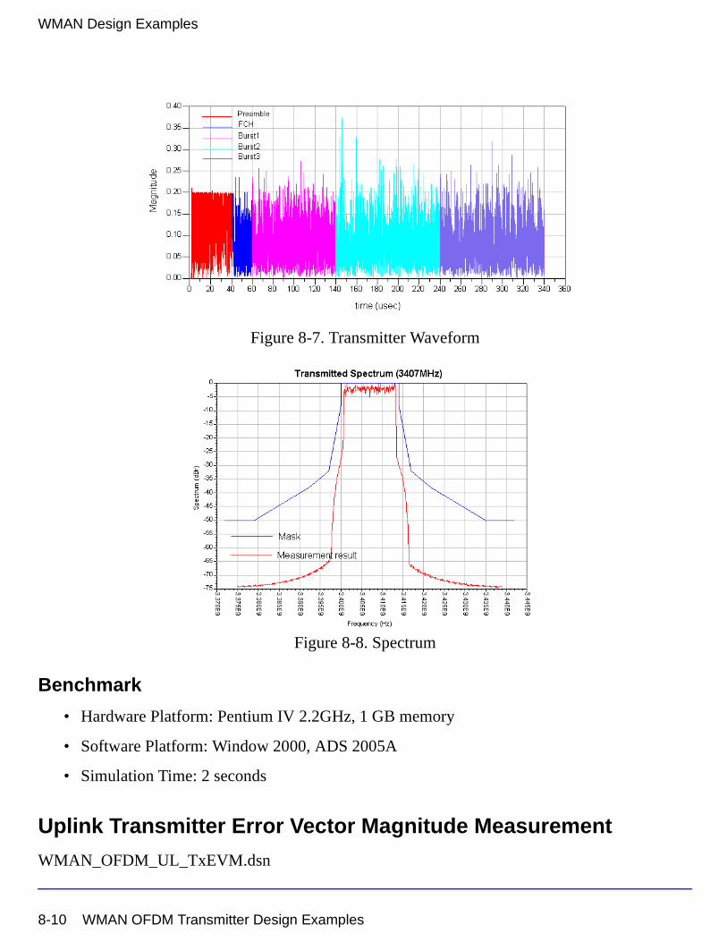
WMAN Design Examples
Figure 8-7. Transmitter Waveform
Figure 8-8. Spectrum
Benchmark
• Hardware Platform: Pentium IV 2.2GHz, 1 GB memory
• Software Platform: Window 2000, ADS 2005A
• Simulation Time: 2 seconds
Uplink Transmitter Error Vector Magnitude Measurement
WMAN_OFDM_UL_TxEVM.dsn
8-10 WMAN OFDM Transmitter Design Examples
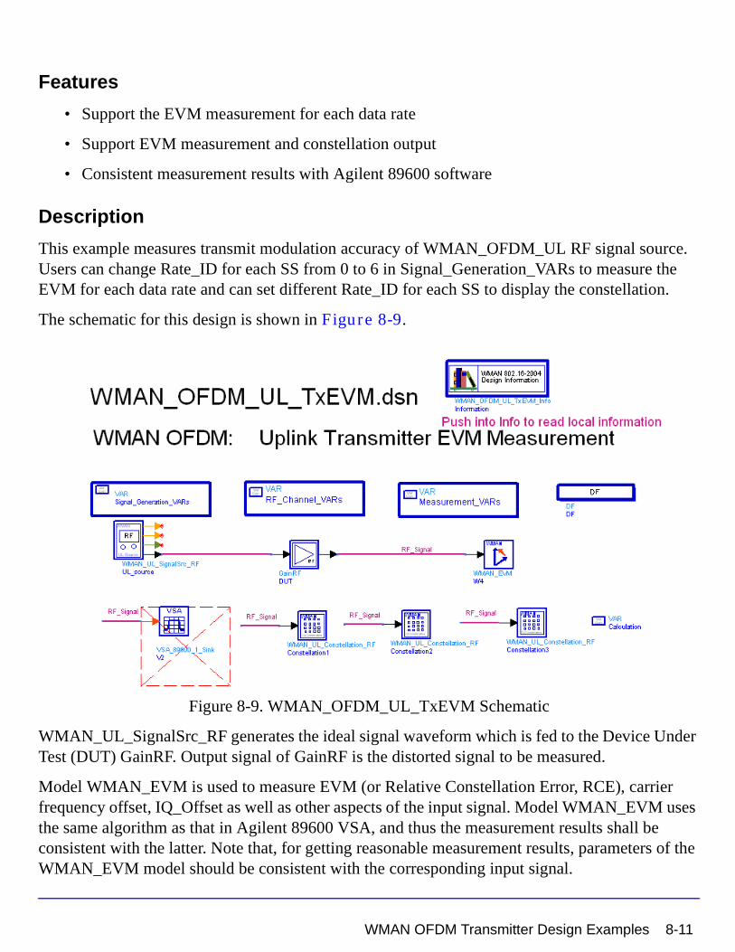
Features
• Support the EVM measurement for each data rate
• Support EVM measurement and constellation output
• Consistent measurement results with Agilent 89600 software
Description
This example measures transmit modulation accuracy of WMAN_OFDM_UL RF signal source. Users can change Rate_ID for each SS from 0 to 6 in Signal_Generation_VARs to measure the EVM for each data rate and can set different Rate_ID for each SS to display the constellation.
The schematic for this design is shown in Figure 8-9.
Figure 8-9. WMAN_OFDM_UL_TxEVM Schematic
WMAN_UL_SignalSrc_RF generates the ideal signal waveform which is fed to the Device Under Test (DUT) GainRF. Output signal of GainRF is the distorted signal to be measured.
Model WMAN_EVM is used to measure EVM (or Relative Constellation Error, RCE), carrier frequency offset, IQ_Offset as well as other aspects of the input signal. Model WMAN_EVM uses the same algorithm as that in Agilent 89600 VSA, and thus the measurement results shall be consistent with the latter. Note that, for getting reasonable measurement results, parameters of the WMAN_EVM model should be consistent with the corresponding input signal.
WMAN OFDM Transmitter Design Examples 8-11
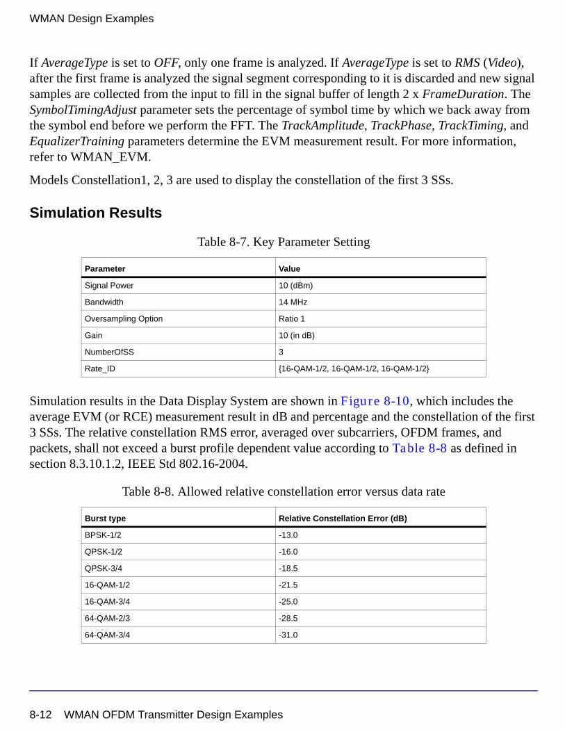
WMAN Design Examples
If AverageType is set to OFF, only one frame is analyzed. If AverageType is set to RMS (Video), after the first frame is analyzed the signal segment corresponding to it is discarded and new signal samples are collected from the input to fill in the signal buffer of length 2 x FrameDuration. The SymbolTimingAdjust parameter sets the percentage of symbol time by which we back away from the symbol end before we perform the FFT. The TrackAmplitude, TrackPhase, TrackTiming, and EqualizerTraining parameters determine the EVM measurement result. For more information, refer to WMAN_EVM.
Models Constellation1, 2, 3 are used to display the constellation of the first 3 SSs.
Simulation Results
Table 8-7. Key Parameter Setting
Simulation results in the Data Display System are shown in Figure 8-10, which includes the average EVM (or RCE) measurement result in dB and percentage and the constellation of the first 3 SSs. The relative constellation RMS error, averaged over subcarriers, OFDM frames, and packets, shall not exceed a burst profile dependent value according to Table 8-8 as defined in section 8.3.10.1.2, IEEE Std 802.16-2004.
Table 8-8. Allowed relative constellation error versus data rate
Parameter Value
Signal Power 10 (dBm)
Bandwidth 14 MHz
Oversampling Option Ratio 1
Gain 10 (in dB)
NumberOfSS 3
Rate_ID {16-QAM-1/2, 16-QAM-1/2, 16-QAM-1/2}
Burst type Relative Constellation Error (dB)
BPSK-1/2 -13.0
QPSK-1/2 -16.0
QPSK-3/4 -18.5
16-QAM-1/2 -21.5
16-QAM-3/4 -25.0
64-QAM-2/3 -28.5
64-QAM-3/4 -31.0
8-12 WMAN OFDM Transmitter Design Examples
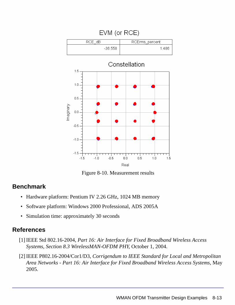
Figure 8-10. Measurement results
Benchmark
• Hardware platform: Pentium IV 2.26 GHz, 1024 MB memory
• Software platform: Windows 2000 Professional, ADS 2005A
• Simulation time: approximately 30 seconds
References
[1] IEEE Std 802.16-2004, Part 16: Air Interface for Fixed Broadband Wireless Access Systems, Section 8.3 WirelessMAN-OFDM PHY, October 1, 2004.
[2] IEEE P802.16-2004/Cor1/D3, Corrigendum to IEEE Standard for Local and Metropolitan Area Networks - Part 16: Air Interface for Fixed Broadband Wireless Access Systems, May 2005.
WMAN OFDM Transmitter Design Examples 8-13
WMAN Design Examples
WMAN OFDM Receiver Design ExamplesThe WMAN_OFDM_Rx project shows WMAN OFDM receiver measurement characteristics including AWGN BER, Sensitivity, Fading BER and Adjacent channel rejection.
Designs for these measurements include:
• WMAN_OFDM_DL_AWGN_BER.dsn
• WMAN_OFDM_DL_RxSensitivity.dsn
• WMAN_OFDM_UL_Fading_BER.dsn
• WMAN_OFDM_UL_RxAdjCh.dsn
Variables used in these designs are listed in Table 8-9.
Table 8-9. VAR Parameters
Downlink BER and PER Measurement on AWGN Channel
WMAN_OFDM_DL_AWGN_BER.dsn Design
Features
• BER and PER measurement on AWGN channel
• Three decoder types supported in downlink receiver: Hard, Soft or CSI
• Multiple Eb/N0 measurement points
Description
WMAN_OFDM_DL_AWGN_BER.dsn measures downlink BER and PER Measurement on AWGN channel. The schematic is shown in Figure 8-11.
Parameter Name Description Default Value
FCarrier RF frequency 3407 (MHz)
Bandwidth Nominal bandwidth 1.75 (MHz)
Power Signal power 0.01W
FFTSize FFT size 256
CyclicPrefix Cyclic prefix 1/4
OversamplingOption Oversampling Option Ratio 1
8-14 WMAN OFDM Receiver Design Examples
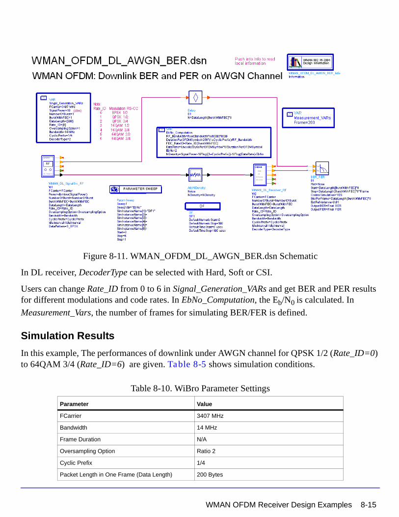
Figure 8-11. WMAN_OFDM_DL_AWGN_BER.dsn Schematic
In DL receiver, DecoderType can be selected with Hard, Soft or CSI.
Users can change Rate_ID from 0 to 6 in Signal_Generation_VARs and get BER and PER results for different modulations and code rates. In EbNo_Computation, the Eb/N0 is calculated. In
Measurement_Vars, the number of frames for simulating BER/FER is defined.
Simulation Results
In this example, The performances of downlink under AWGN channel for QPSK 1/2 (Rate_ID=0) to 64QAM 3/4 (Rate_ID=6) are given. Table 8-5 shows simulation conditions.
Table 8-10. WiBro Parameter Settings
Parameter Value
FCarrier 3407 MHz
Bandwidth 14 MHz
Frame Duration N/A
Oversampling Option Ratio 2
Cyclic Prefix 1/4
Packet Length in One Frame (Data Length) 200 Bytes
WMAN OFDM Receiver Design Examples 8-15
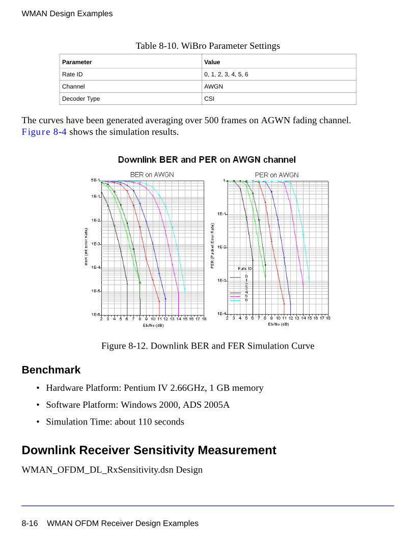
WMAN Design Examples
The curves have been generated averaging over 500 frames on AGWN fading channel. Figure 8-4 shows the simulation results.
Figure 8-12. Downlink BER and FER Simulation Curve
Benchmark
• Hardware Platform: Pentium IV 2.66GHz, 1 GB memory
• Software Platform: Windows 2000, ADS 2005A
• Simulation Time: about 110 seconds
Downlink Receiver Sensitivity Measurement
WMAN_OFDM_DL_RxSensitivity.dsn Design
Rate ID 0, 1, 2, 3, 4, 5, 6
Channel AWGN
Decoder Type CSI
Table 8-10. WiBro Parameter Settings
Parameter Value
8-16 WMAN OFDM Receiver Design Examples
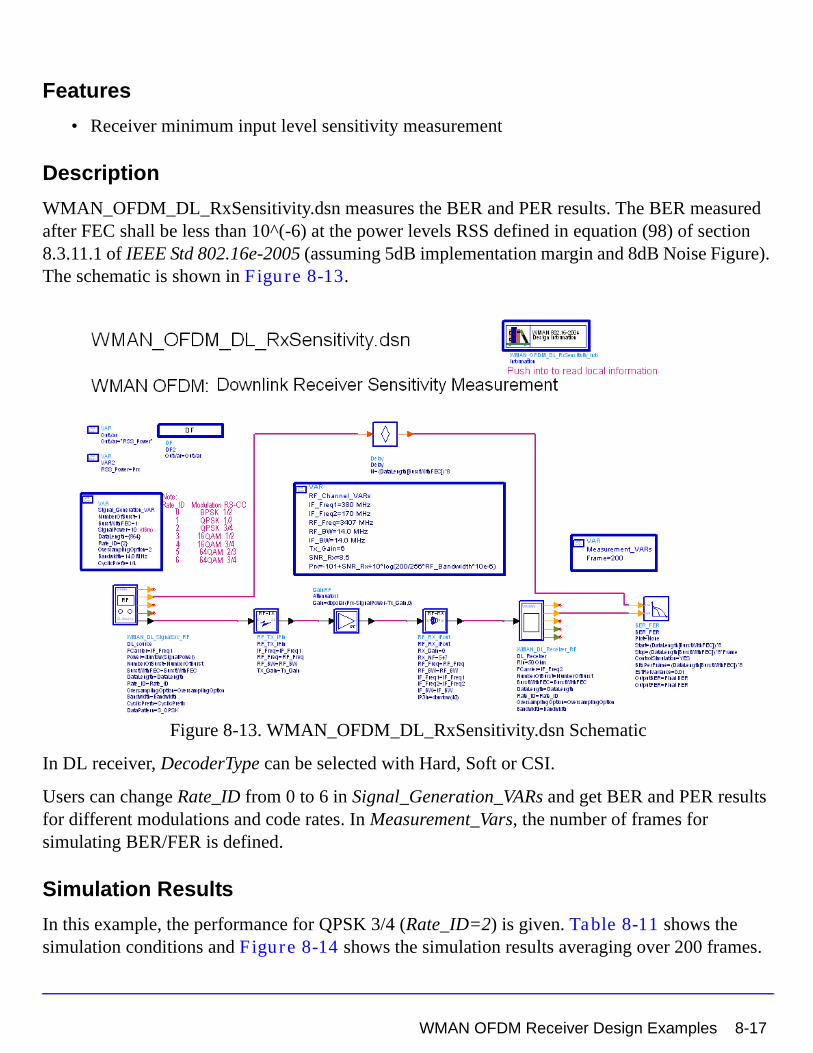
Features
• Receiver minimum input level sensitivity measurement
Description
WMAN_OFDM_DL_RxSensitivity.dsn measures the BER and PER results. The BER measured after FEC shall be less than 10^(-6) at the power levels RSS defined in equation (98) of section 8.3.11.1 of IEEE Std 802.16e-2005 (assuming 5dB implementation margin and 8dB Noise Figure). The schematic is shown in Figure 8-13.
Figure 8-13. WMAN_OFDM_DL_RxSensitivity.dsn Schematic
In DL receiver, DecoderType can be selected with Hard, Soft or CSI.
Users can change Rate_ID from 0 to 6 in Signal_Generation_VARs and get BER and PER results for different modulations and code rates. In Measurement_Vars, the number of frames for simulating BER/FER is defined.
Simulation Results
In this example, the performance for QPSK 3/4 (Rate_ID=2) is given. Table 8-11 shows the simulation conditions and Figure 8-14 shows the simulation results averaging over 200 frames.
WMAN OFDM Receiver Design Examples 8-17
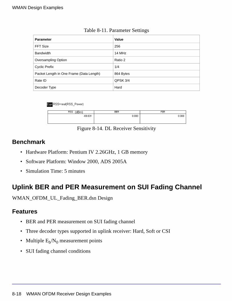
WMAN Design Examples
Figure 8-14. DL Receiver Sensitivity
Benchmark
• Hardware Platform: Pentium IV 2.26GHz, 1 GB memory
• Software Platform: Window 2000, ADS 2005A
• Simulation Time: 5 minutes
Uplink BER and PER Measurement on SUI Fading Channel
WMAN_OFDM_UL_Fading_BER.dsn Design
Features
• BER and PER measurement on SUI fading channel
• Three decoder types supported in uplink receiver: Hard, Soft or CSI
• Multiple Eb/N0 measurement points
• SUI fading channel conditions
Table 8-11. Parameter Settings
Parameter Value
FFT Size 256
Bandwidth 14 MHz
Oversampling Option Ratio 2
Cyclic Prefix 1/4
Packet Length in One Frame (Data Length) 864 Bytes
Rate ID QPSK 3/4
Decoder Type Hard
8-18 WMAN OFDM Receiver Design Examples
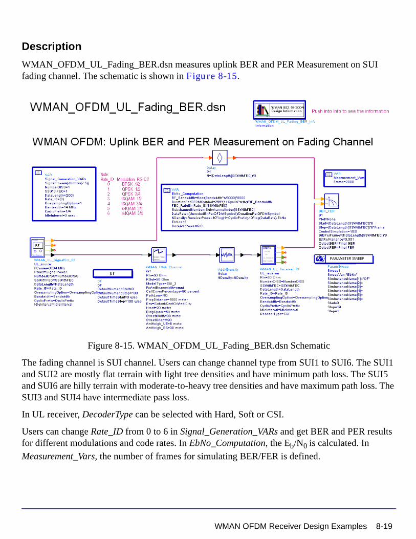
Description
WMAN_OFDM_UL_Fading_BER.dsn measures uplink BER and PER Measurement on SUI fading channel. The schematic is shown in Figure 8-15.
Figure 8-15. WMAN_OFDM_UL_Fading_BER.dsn Schematic
The fading channel is SUI channel. Users can change channel type from SUI1 to SUI6. The SUI1 and SUI2 are mostly flat terrain with light tree densities and have minimum path loss. The SUI5 and SUI6 are hilly terrain with moderate-to-heavy tree densities and have maximum path loss. The SUI3 and SUI4 have intermediate pass loss.
In UL receiver, DecoderType can be selected with Hard, Soft or CSI.
Users can change Rate_ID from 0 to 6 in Signal_Generation_VARs and get BER and PER results for different modulations and code rates. In EbNo_Computation, the Eb/N0 is calculated. In
Measurement_Vars, the number of frames for simulating BER/FER is defined.
WMAN OFDM Receiver Design Examples 8-19
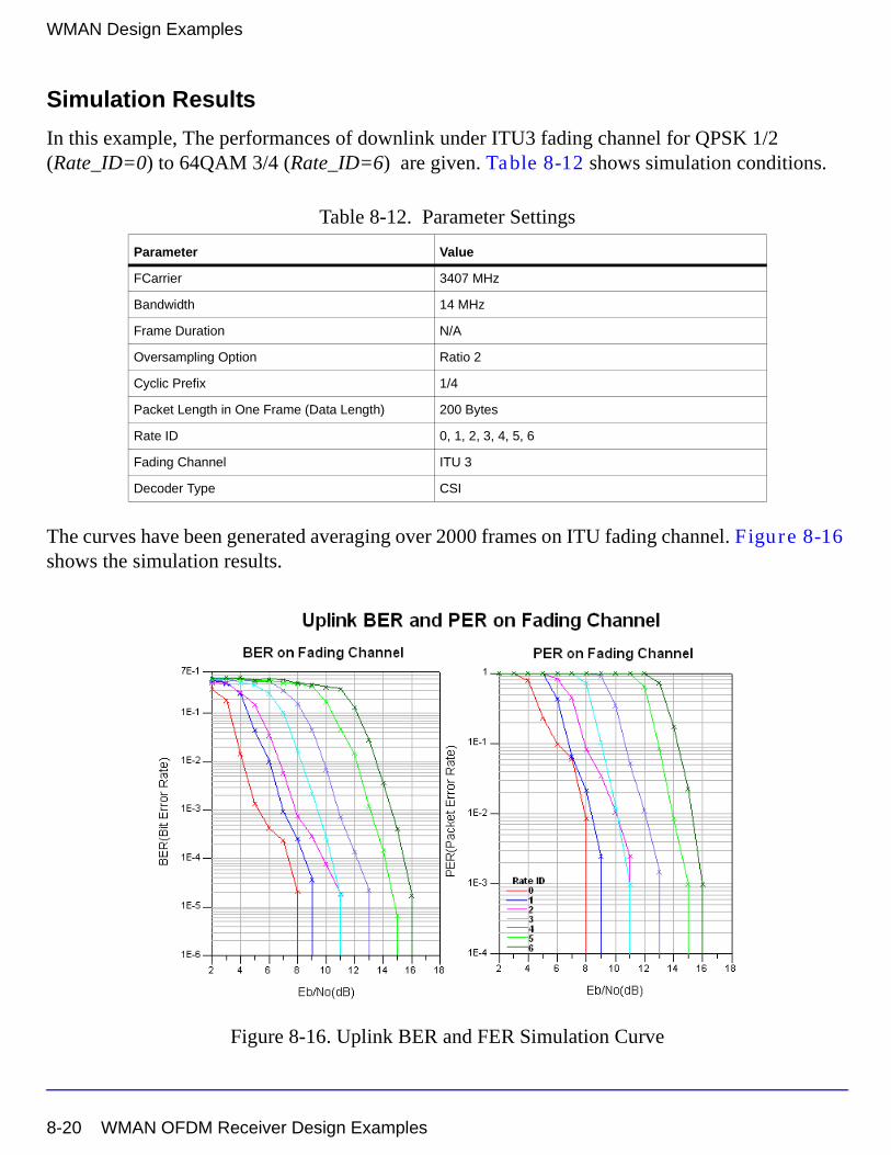
WMAN Design Examples
Simulation Results
In this example, The performances of downlink under ITU3 fading channel for QPSK 1/2 (Rate_ID=0) to 64QAM 3/4 (Rate_ID=6) are given. Table 8-12 shows simulation conditions.
The curves have been generated averaging over 2000 frames on ITU fading channel. Figure 8-16 shows the simulation results.
Figure 8-16. Uplink BER and FER Simulation Curve
Table 8-12. Parameter Settings
Parameter Value
FCarrier 3407 MHz
Bandwidth 14 MHz
Frame Duration N/A
Oversampling Option Ratio 2
Cyclic Prefix 1/4
Packet Length in One Frame (Data Length) 200 Bytes
Rate ID 0, 1, 2, 3, 4, 5, 6
Fading Channel ITU 3
Decoder Type CSI
8-20 WMAN OFDM Receiver Design Examples
Benchmark
• Hardware Platform: Pentium IV 2.66GHz, 1 GB memory
• Software Platform: Windows 2000, ADS 2005A
• Simulation Time: about 3.6 hours for 16QAM 1/2 (Rate_ID=3)
WMAN OFDM Uplink Receiver Adjacent and Alternate Channel Rejection
WMAN_OFDM_UL_RxAdjCh.dsn Design
Features
• Spectrum of desired signal and interference
• BER and FER measurement of desired signal
Description
This example measures the adjacent and alternate channel rejection defined in section 8.4.13.2 IEEE Std 802.16-2004. The schematic is shown in Figure 8-5.
WMAN OFDM Receiver Design Examples 8-21
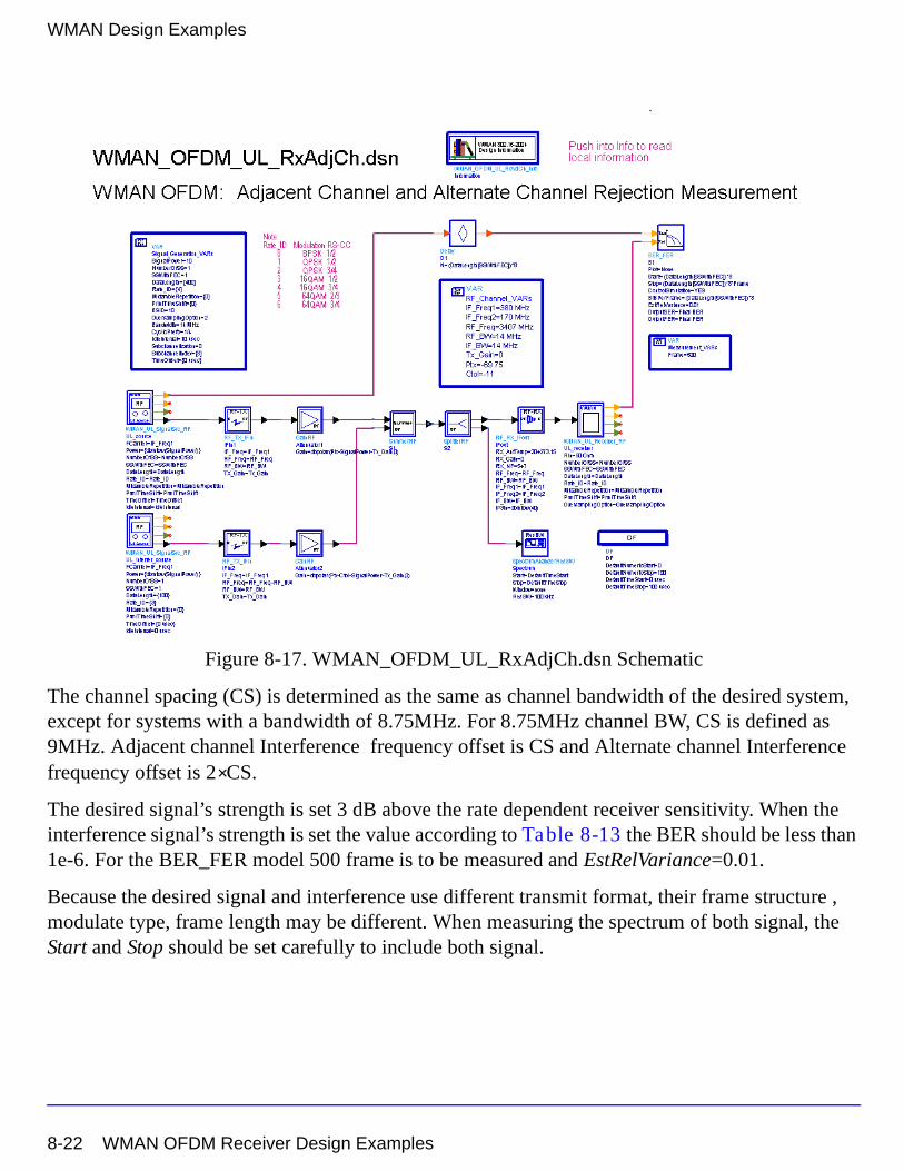
WMAN Design Examples
Figure 8-17. WMAN_OFDM_UL_RxAdjCh.dsn Schematic
The channel spacing (CS) is determined as the same as channel bandwidth of the desired system, except for systems with a bandwidth of 8.75MHz. For 8.75MHz channel BW, CS is defined as 9MHz. Adjacent channel Interference frequency offset is CS and Alternate channel Interference frequency offset is 2 CS.
The desired signal’s strength is set 3 dB above the rate dependent receiver sensitivity. When the interference signal’s strength is set the value according to Table 8-13 the BER should be less than 1e-6. For the BER_FER model 500 frame is to be measured and EstRelVariance=0.01.
Because the desired signal and interference use different transmit format, their frame structure , modulate type, frame length may be different. When measuring the spectrum of both signal, the Start and Stop should be set carefully to include both signal.
×
8-22 WMAN OFDM Receiver Design Examples
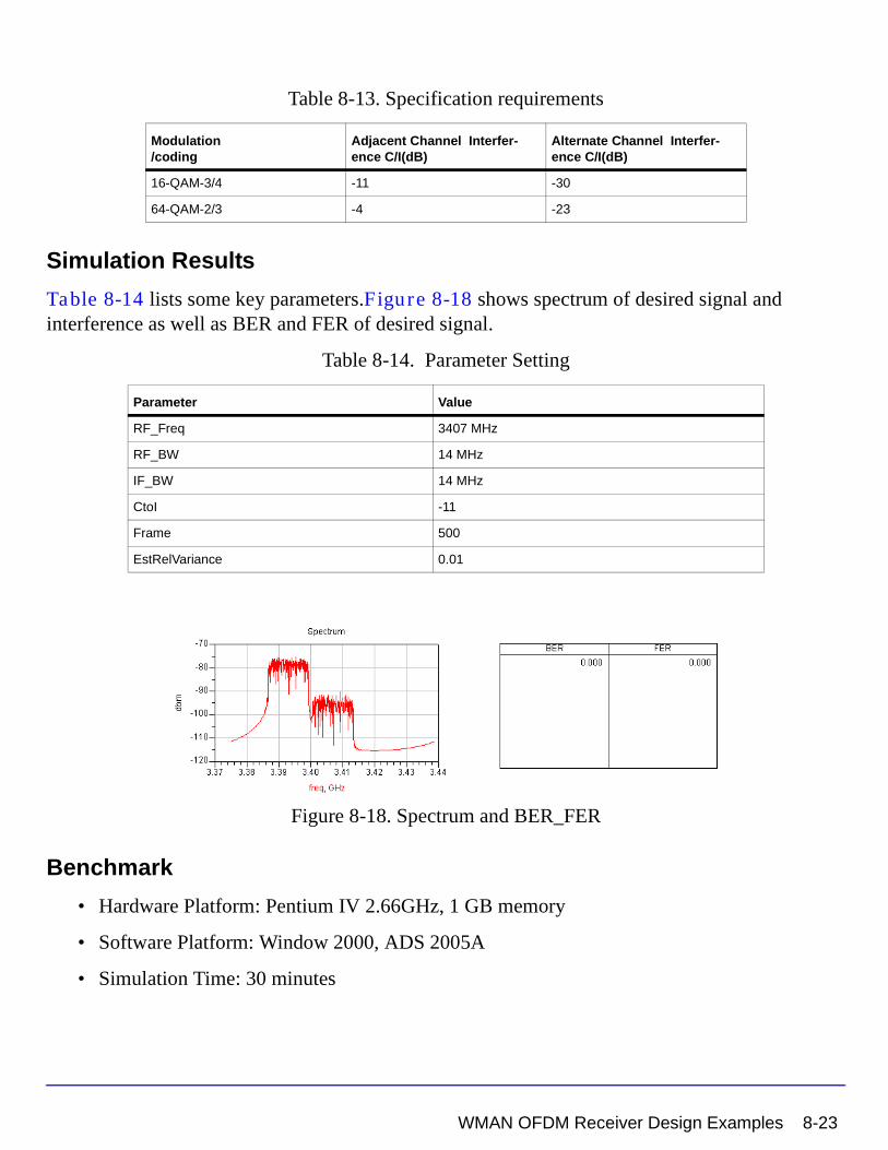
Table 8-13. Specification requirements
Simulation Results
Table 8-14 lists some key parameters.Figure 8-18 shows spectrum of desired signal and interference as well as BER and FER of desired signal.
Table 8-14. Parameter Setting
Figure 8-18. Spectrum and BER_FER
Benchmark
• Hardware Platform: Pentium IV 2.66GHz, 1 GB memory
• Software Platform: Window 2000, ADS 2005A
• Simulation Time: 30 minutes
Modulation/coding
Adjacent Channel Interfer-ence C/I(dB)
Alternate Channel Interfer-ence C/I(dB)
16-QAM-3/4 -11 -30
64-QAM-2/3 -4 -23
Parameter Value
RF_Freq 3407 MHz
RF_BW 14 MHz
IF_BW 14 MHz
CtoI -11
Frame 500
EstRelVariance 0.01
WMAN OFDM Receiver Design Examples 8-23
WMAN Design Examples
References
[1] IEEE Std 802.16-2004, Part 16: Air Interface for Fixed Broadband Wireless Access Systems, Section 8.3 WirelessMAN-OFDM PHY, October 1, 2004.
[2] IEEE P802.16-2004/Cor1/D3, Corrigendum to IEEE Standard for Local and Metropolitan Area Networks - Part 16: Air Interface for Fixed Broadband Wireless Access Systems, May 2005.
WMAN OFDM FrameDuration Design ExamplesThe WMAN_OFDM_FrameDuration project shows WMAN OFDM FrameDuration measurement characteristics including Fading BER, AWGN BER, EVM and Waveform.
Designs for these measurements include:
• WMAN_OFDM_DL_Fading_BER_FD.dsn
• WMAN_OFDM_DL_TxEVM_FD.dsn
• WMAN_OFDM_DL_TxWaveform_FD.dsn
• WMAN_OFDM_UL_AWGN_BER_FD.dsn
• WMAN_OFDM_UL_SubCh_TxEVM_FD.dsn
Variables used in these designs are listed in Table 8-15.
Table 8-15. VAR Parameters
Parameter Name Description Default Value
FCarrier RF frequency 3407 (MHz)
Bandwidth Nominal bandwidth 1.75 (MHz)
Power Signal power 0.01W
FFTSize FFT size 256
CyclicPrefix Cyclic prefix 1/4
OversamplingOption Oversampling Option Ratio 1
FrameMode Frame Mode FDD
DL_Ratio Downlink Ratio 0.5
FrameDuration Frame Duration 5 ms
8-24 WMAN OFDM FrameDuration Design Examples
Downlink BER and PER Measurement on SUI Fading Channel
WMAN_OFDM_DL_Fading_BER_FD.dsn Design
Features
• BER and PER measurement on SUI fading channel
• Frame structure supported (FrameDuation from 2.5 msec to 20 msec)
• Three decoder types supported in downlink receiver: Hard, Soft or CSI
• Multiple Eb/N0 measurement points
• SUI fading channel conditions
Description
WMAN_OFDM_DL_Fading_BER_FD.dsn measures downlink BER and PER Measurement on SUI fading channel. The schematic is shown in Figure 8-19.
Figure 8-19. WMAN_OFDM_DL_Fading_BER_FD.dsn Schematic
In DL source, the frame structure is supported.
WMAN OFDM FrameDuration Design Examples 8-25
WMAN Design Examples
The fading channel is SUI channel. Users can change channel type from SUI1 to SUI6. The SUI1 and SUI2 are mostly flat terrain with light tree densities and have minimum path loss. The SUI5 and SUI6 are hilly terrain with moderate-to-heavy tree densities and have maximum path loss. The SUI3 and SUI4 have intermediate pass loss.
In DL receiver, DecoderType can be selected with Hard, Soft or CSI.
Users can change Rate_ID from 0 to 6 in SignalSourseVARs and get BER and PER results for different modulations and code rates. In EbNo_Computation, the Eb/N0 is calculated. In
Measurement_Vars, the number of frames for simulating BER/FER is defined.
Simulation Results
In this example, The performances of downlink under ITU3 fading channel for QPSK 1/2 (Rate_ID=0) to 64QAM 3/4 (Rate_ID=6) are given. Table 8-5 shows simulation conditions.
The curves have been generated averaging over 100 frames on ITU fading channel. Figure 8-4 shows the simulation results.
Table 8-16. Parameter Settings
Parameter Value
FCarrier 3407 MHz
Bandwidth 14 MHz
Frame Duration 5 msec
Oversampling Option Ratio 2
Cyclic Prefix 1/4
Packet Length in One Frame (Data Length) 4000 Bytes
Rate ID 0, 1, 2, 3, 4, 5, 6
Fading Channel ITU 3
Decoder Type CSI
8-26 WMAN OFDM FrameDuration Design Examples
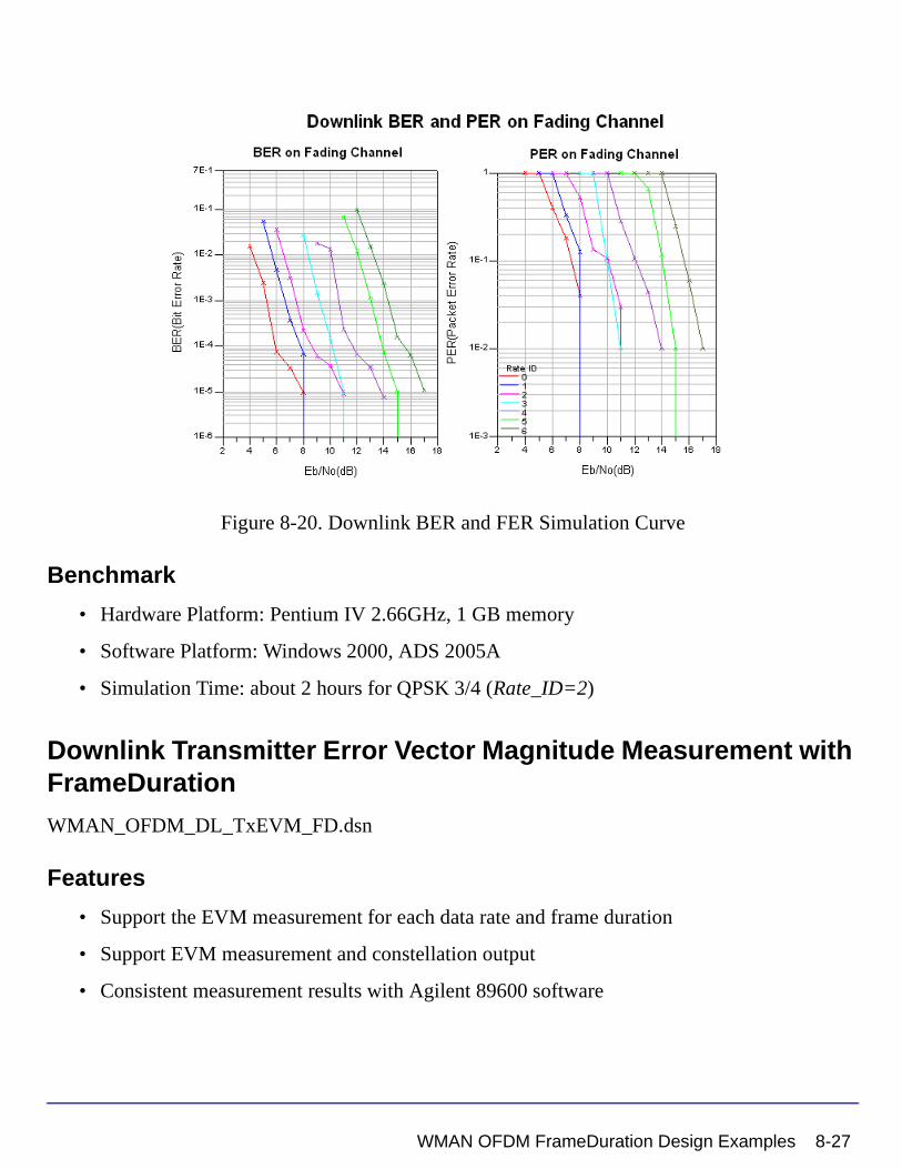
Figure 8-20. Downlink BER and FER Simulation Curve
Benchmark
• Hardware Platform: Pentium IV 2.66GHz, 1 GB memory
• Software Platform: Windows 2000, ADS 2005A
• Simulation Time: about 2 hours for QPSK 3/4 (Rate_ID=2)
Downlink Transmitter Error Vector Magnitude Measurement with FrameDuration
WMAN_OFDM_DL_TxEVM_FD.dsn
Features
• Support the EVM measurement for each data rate and frame duration
• Support EVM measurement and constellation output
• Consistent measurement results with Agilent 89600 software
WMAN OFDM FrameDuration Design Examples 8-27
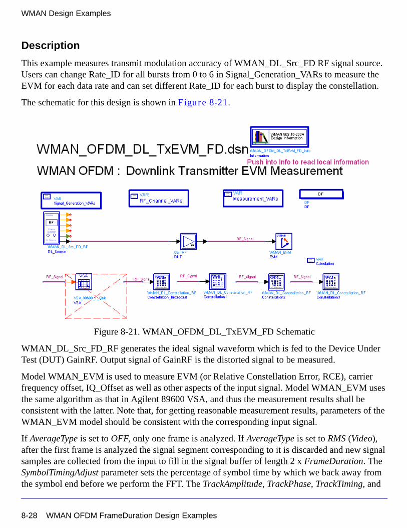
WMAN Design Examples
Description
This example measures transmit modulation accuracy of WMAN_DL_Src_FD RF signal source. Users can change Rate_ID for all bursts from 0 to 6 in Signal_Generation_VARs to measure the EVM for each data rate and can set different Rate_ID for each burst to display the constellation.
The schematic for this design is shown in Figure 8-21.
Figure 8-21. WMAN_OFDM_DL_TxEVM_FD Schematic
WMAN_DL_Src_FD_RF generates the ideal signal waveform which is fed to the Device Under Test (DUT) GainRF. Output signal of GainRF is the distorted signal to be measured.
Model WMAN_EVM is used to measure EVM (or Relative Constellation Error, RCE), carrier frequency offset, IQ_Offset as well as other aspects of the input signal. Model WMAN_EVM uses the same algorithm as that in Agilent 89600 VSA, and thus the measurement results shall be consistent with the latter. Note that, for getting reasonable measurement results, parameters of the WMAN_EVM model should be consistent with the corresponding input signal.
If AverageType is set to OFF, only one frame is analyzed. If AverageType is set to RMS (Video), after the first frame is analyzed the signal segment corresponding to it is discarded and new signal samples are collected from the input to fill in the signal buffer of length 2 x FrameDuration. The SymbolTimingAdjust parameter sets the percentage of symbol time by which we back away from the symbol end before we perform the FFT. The TrackAmplitude, TrackPhase, TrackTiming, and
8-28 WMAN OFDM FrameDuration Design Examples
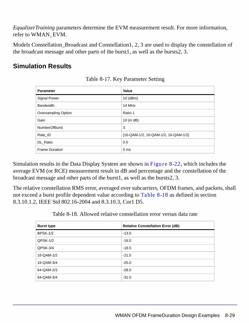
EqualizerTraining parameters determine the EVM measurement result. For more information, refer to WMAN_EVM.
Models Constellation_Broadcast and Constellation1, 2, 3 are used to display the constellation of the broadcast message and other parts of the burst1, as well as the bursts2, 3.
Simulation Results
Table 8-17. Key Parameter Setting
Simulation results in the Data Display System are shown in Figure 8-22, which includes the average EVM (or RCE) measurement result in dB and percentage and the constellation of the broadcast message and other parts of the burst1, as well as the bursts2, 3.
The relative constellation RMS error, averaged over subcarriers, OFDM frames, and packets, shall not exceed a burst profile dependent value according to Table 8-18 as defined in section 8.3.10.1.2, IEEE Std 802.16-2004 and 8.3.10.3, Cor1 D5.
Table 8-18. Allowed relative constellation error versus data rate
Parameter Value
Signal Power 10 (dBm)
Bandwidth 14 MHz
Oversampling Option Ratio 1
Gain 10 (in dB)
NumberOfBurst 3
Rate_ID {16-QAM-1/2, 16-QAM-1/2, 16-QAM-1/2}
DL_Ratio 0.5
Frame Duration 5 ms
Burst type Relative Constellation Error (dB)
BPSK-1/2 -13.0
QPSK-1/2 -16.0
QPSK-3/4 -18.5
16-QAM-1/2 -21.5
16-QAM-3/4 -25.0
64-QAM-2/3 -28.5
64-QAM-3/4 -31.0
WMAN OFDM FrameDuration Design Examples 8-29
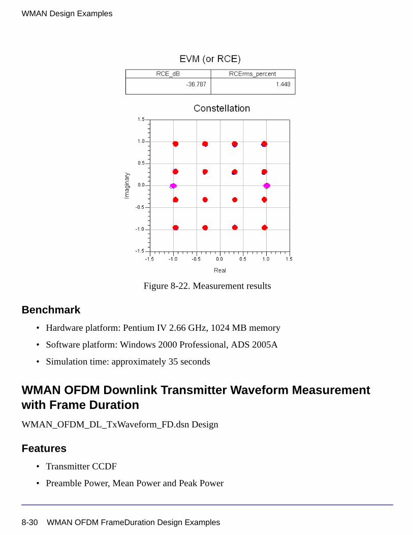
WMAN Design Examples
Figure 8-22. Measurement results
Benchmark
• Hardware platform: Pentium IV 2.66 GHz, 1024 MB memory
• Software platform: Windows 2000 Professional, ADS 2005A
• Simulation time: approximately 35 seconds
WMAN OFDM Downlink Transmitter Waveform Measurement with Frame Duration
WMAN_OFDM_DL_TxWaveform_FD.dsn Design
Features
• Transmitter CCDF
• Preamble Power, Mean Power and Peak Power
8-30 WMAN OFDM FrameDuration Design Examples
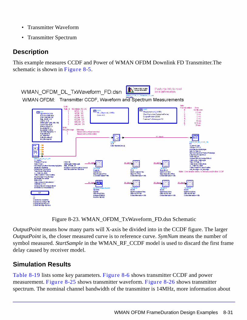
• Transmitter Waveform
• Transmitter Spectrum
Description
This example measures CCDF and Power of WMAN OFDM Downlink FD Transmitter.The schematic is shown in Figure 8-5.
Figure 8-23. WMAN_OFDM_TxWaveform_FD.dsn Schematic
OutputPoint means how many parts will X-axis be divided into in the CCDF figure. The larger OutputPoint is, the closer measured curve is to reference curve. SymNum means the number of symbol measured. StartSample in the WMAN_RF_CCDF model is used to discard the first frame delay caused by receiver model.
Simulation Results
Table 8-19 lists some key parameters. Figure 8-6 shows transmitter CCDF and power measurement. Figure 8-25 shows transmitter waveform. Figure 8-26 shows transmitter spectrum. The nominal channel bandwidth of the transmitter is 14MHz, more information about
WMAN OFDM FrameDuration Design Examples 8-31
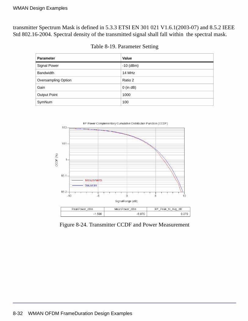
WMAN Design Examples
transmitter Spectrum Mask is defined in 5.3.3 ETSI EN 301 021 V1.6.1(2003-07) and 8.5.2 IEEE Std 802.16-2004. Spectral density of the transmitted signal shall fall within the spectral mask.
Table 8-19. Parameter Setting
Figure 8-24. Transmitter CCDF and Power Measurement
Parameter Value
Signal Power -10 (dBm)
Bandwidth 14 MHz
Oversampling Option Ratio 2
Gain 0 (in dB)
Output Point 1000
SymNum 100
8-32 WMAN OFDM FrameDuration Design Examples
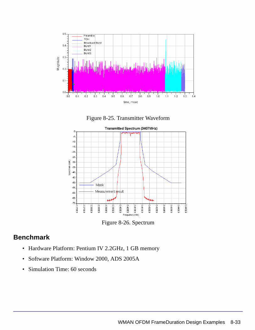
Figure 8-25. Transmitter Waveform
Figure 8-26. Spectrum
Benchmark
• Hardware Platform: Pentium IV 2.2GHz, 1 GB memory
• Software Platform: Window 2000, ADS 2005A
• Simulation Time: 60 seconds
WMAN OFDM FrameDuration Design Examples 8-33
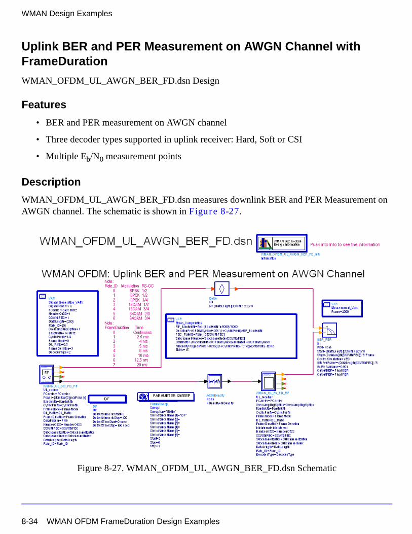
WMAN Design Examples
Uplink BER and PER Measurement on AWGN Channel with FrameDuration
WMAN_OFDM_UL_AWGN_BER_FD.dsn Design
Features
• BER and PER measurement on AWGN channel
• Three decoder types supported in uplink receiver: Hard, Soft or CSI
• Multiple Eb/N0 measurement points
Description
WMAN_OFDM_UL_AWGN_BER_FD.dsn measures downlink BER and PER Measurement on AWGN channel. The schematic is shown in Figure 8-27.
Figure 8-27. WMAN_OFDM_UL_AWGN_BER_FD.dsn Schematic
8-34 WMAN OFDM FrameDuration Design Examples
Users can change Rate_ID from 0 to 6 in Signal_Generation_VARs and get BER and PER results for different modulations and code rates. In EbNo_Computation, the Eb/N0 and corresponding
NDensity is calculated. In Measurement_Vars, the number of frames for simulating BER/FER is defined.
Simulation Results
In this example, The performances of uplink PUSC for BPSK 1/2 (Rate_ID=0), QPSK 1/2 (Rate_ID=1), QPSK 3/4 (Rate_ID=2), 16QAM 1/2 (Rate_ID=3), 16QAM 3/4 (Rate_ID=4), 64QAM 2/3 (Rate_ID=5) and 64QAM 3/4 (Rate_ID=6) are given. Table 8-20 shows the simulation conditions.
The curves have been generated averaging over 2000 frames. Figure 8-28 shows the simulation results.
Table 8-20. Parameter Settings
Parameter Value
FCarrier 3407 MHz
Zone Type UL PUSC
FFT Size 256
Bandwidth 14 MHz
Frame Duration 5 msec
Oversampling Option Ratio 2
Cyclic Prefix 1/4
Packet Length in One Frame (Data Length) 200 Bytes
Rate ID BPSK 1/2, QPSK 1/2, QPSK 3/4, 16QAM 1/2, 16QAM 3/4, 64QAM 2/3 and 64QAM 3/4
Decoder Type CSI
WMAN OFDM FrameDuration Design Examples 8-35
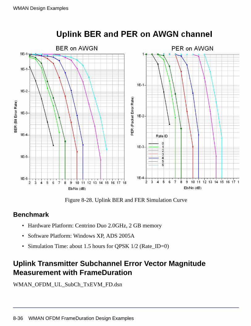
WMAN Design Examples
Figure 8-28. Uplink BER and FER Simulation Curve
Benchmark
• Hardware Platform: Centrino Duo 2.0GHz, 2 GB memory
• Software Platform: Windows XP, ADS 2005A
• Simulation Time: about 1.5 hours for QPSK 1/2 (Rate_ID=0)
Uplink Transmitter Subchannel Error Vector Magnitude Measurement with FrameDuration
WMAN_OFDM_UL_SubCh_TxEVM_FD.dsn
8-36 WMAN OFDM FrameDuration Design Examples
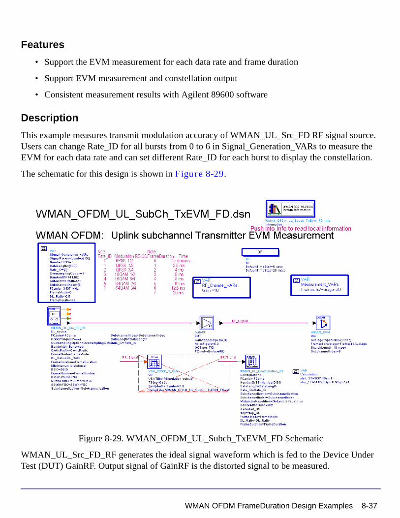
Features
• Support the EVM measurement for each data rate and frame duration
• Support EVM measurement and constellation output
• Consistent measurement results with Agilent 89600 software
Description
This example measures transmit modulation accuracy of WMAN_UL_Src_FD RF signal source. Users can change Rate_ID for all bursts from 0 to 6 in Signal_Generation_VARs to measure the EVM for each data rate and can set different Rate_ID for each burst to display the constellation.
The schematic for this design is shown in Figure 8-29.
Figure 8-29. WMAN_OFDM_UL_Subch_TxEVM_FD Schematic
WMAN_UL_Src_FD_RF generates the ideal signal waveform which is fed to the Device Under Test (DUT) GainRF. Output signal of GainRF is the distorted signal to be measured.
WMAN OFDM FrameDuration Design Examples 8-37
WMAN Design Examples
Model WMAN_EVM is used to measure EVM (or Relative Constellation Error, RCE), carrier frequency offset, IQ_Offset as well as other aspects of the input signal. Model WMAN_EVM uses the same algorithm as that in Agilent 89600 VSA, and thus the measurement results shall be consistent with the latter. Note that, for getting reasonable measurement results, parameters of the WMAN_EVM model should be consistent with the corresponding input signal. For more details on WMAN_EVM, see document of this model.
Simulation Results
Table 8-21. Parameter Setting
Simulation results in the Data Display System are shown in Figure 8-30, which includes the average EVM (or RCE) measurement result in dB and percentage and the constellation of the broadcast message and other parts of the burst1, as well as the bursts2, 3.
The relative constellation RMS error, averaged over subcarriers, OFDM frames, and packets, shall not exceed a burst profile dependent value according to Table 8-22 as defined in section 8.3.10.1.2, IEEE Std 802.16-2004 and 8.3.10.3, Cor1 D5.
Table 8-22. Allowed relative constellation error versus data rate
Parameter Value
Signal Power 10 (dBm)
Bandwidth 14 MHz
Oversampling Option Ratio 1
Gain 10 (in dB)
NumberOfSS 1
Rate_ID 16-QAM-1/2
DL_Ratio 0.5
Frame Duration 5 ms
Burst type Relative Constellation Error (dB)
BPSK-1/2 -13.0
QPSK-1/2 -16.0
QPSK-3/4 -18.5
16-QAM-1/2 -21.5
16-QAM-3/4 -25.0
64-QAM-2/3 -29.0
64-QAM-3/4 -30.0
8-38 WMAN OFDM FrameDuration Design Examples
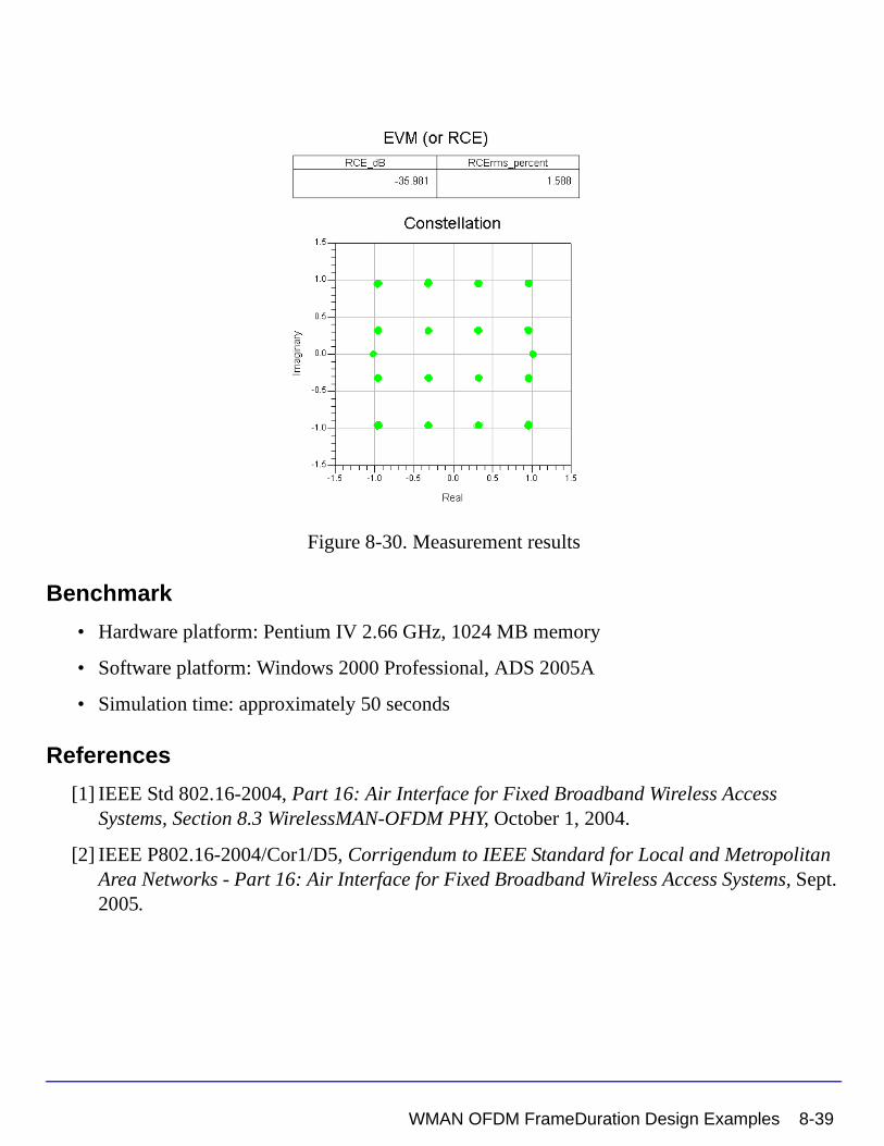
Figure 8-30. Measurement results
Benchmark
• Hardware platform: Pentium IV 2.66 GHz, 1024 MB memory
• Software platform: Windows 2000 Professional, ADS 2005A
• Simulation time: approximately 50 seconds
References
[1] IEEE Std 802.16-2004, Part 16: Air Interface for Fixed Broadband Wireless Access Systems, Section 8.3 WirelessMAN-OFDM PHY, October 1, 2004.
[2] IEEE P802.16-2004/Cor1/D5, Corrigendum to IEEE Standard for Local and Metropolitan Area Networks - Part 16: Air Interface for Fixed Broadband Wireless Access Systems, Sept. 2005.
WMAN OFDM FrameDuration Design Examples 8-39

WMAN Design Examples
8-40 WMAN OFDM FrameDuration Design Examples
Index
Numerics802.16-2004, 1-1802.16e, 1-1AAWGN, 1-9
Ccapacity, 1-1CCDF, 1-9cell radius, 1-1CP, 1-9CSMA/CA, 1-9
Ddesign examples, 8-1DL, 1-9
EEVM, 1-9examples, 8-1
FFEC, 1-9FFT, 1-9Fixed WiMAX, 1-1, 1-2
IIEEE, 1-9IEEE 802.16, 1-1IFFT, 1-9
MMAC, 1-9
OOFDM, 1-1, 1-9
PPA, 1-9PER, 1-9PHY, 1-1, 1-9PLCP, 1-9PSDU, 1-9
QQPSK, 1-9
RRCE, 1-9RF, 1-9RX, 1-9
SSDU, 1-9
Ttriple-play services, 1-1TX, 1-9
UUL, 1-9
WWDL, 1-9WiMAX, 1-1, 1-9WMAN, 1-9WMAN_BrdcstMessage, 7-2WMAN_BurstWoFEC, 5-2WMAN_CRC_Coder, 3-2WMAN_DataPattern, 7-6WMAN_DCD, 7-9WMAN_Demapper, 6-2WMAN_DemuxOFDMSym, 5-5WMAN_DL_ChEstimator, 6-5WMAN_DL_Constellation_RF, 4-2WMAN_DL_DemuxBurst, 5-7WMAN_DL_DemuxBurst_FD, 5-10WMAN_DL_DemuxFrame, 6-8WMAN_DL_DemuxFrame_FD, 6-14WMAN_DL_FrameSync, 6-22WMAN_DL_FreqSync, 6-27WMAN_DL_MAP, 7-11WMAN_DL_MuxBurst, 5-13WMAN_DL_MuxBurst_FD, 5-16WMAN_DL_MuxFrame, 5-19WMAN_DL_PhaseTracker, 6-31WMAN_DL_Pilot, 7-14WMAN_DL_Receiver, 6-34WMAN_DL_Receiver_RF, 6-42WMAN_DL_RF_CCDF_FD, 4-6
Index-1
WMAN_DL_Rx_FD, 6-52WMAN_DL_Rx_FD_RF, 6-61WMAN_DL_SignalSrc, 7-17WMAN_DL_SignalSrc_RF, 7-24WMAN_DL_SpecFlat, 4-10WMAN_DL_Src_FD, 7-33WMAN_DL_Src_FD_RF, 7-43WMAN_DLFP, 7-54WMAN_FEC, 3-5WMAN_FEC_Decoder, 3-9WMAN_FWA_Channel, 2-2WMAN_MACHeader, 7-57WMAN_MACPDU, 7-59WMAN_Preamble, 7-61WMAN_Puncturer, 3-11WMAN_RF_CCDF, 4-13WMAN_RSDecoder, 3-13WMAN_Scrambler, 3-18WMAN_UCD, 7-64WMAN_UL_ChEstimator, 6-72WMAN_UL_Constellation_RF, 4-15WMAN_UL_DemuxBurst, 5-25WMAN_UL_DemuxFrame, 6-77WMAN_UL_DemuxFrame_FD, 6-83WMAN_UL_FrameSync, 6-90WMAN_UL_FreqSync, 6-97WMAN_UL_MAP, 7-66WMAN_UL_MuxBurst, 5-28WMAN_UL_MuxFrame, 5-31WMAN_UL_MuxOFDMSym, 5-37WMAN_UL_PhaseTracker, 6-103WMAN_UL_Pilot, 7-69WMAN_UL_Receiver, 6-107WMAN_UL_Receiver_RF, 6-117WMAN_UL_RF_CCDF_FD, 4-19WMAN_UL_Rx_FD, 6-129WMAN_UL_Rx_FD_RF, 6-139WMAN_UL_SignalSrc, 7-73WMAN_UL_SignalSrc_RF, 7-83WMAN_UL_SpecFlat, 4-23WMAN_UL_Src_FD, 7-95WMAN_UL_Src_FD_RF, 7-107
Index-2