Embed Size (px)
Citation preview

Product cataloguesProduktkatalog
Fixing systems for photovoltaic panelsBefestigungssysteme für Photovoltaik-Module
FVT
6/11
EN/
DETeknomega s.r.l.via E. Fermi, 27 - 20090 Buccinasco (MI)tel. +39.02.45707533 - +39.02.48844281Fax +39.02.45705673e-mail: [email protected]
Teknomega GmbH & Co.KGHauptstr. 76 - 67715 Geiselbergtel. 06307 / 9127-127Fax 06307 / 9127-128e-mail: [email protected]

Page-Seite 6 Page-Seite 6 Page-Seite 7 Page-Seite 6-7
Page-Seite 8-9 Page-Seite 10-11 Page-Seite 10 Page-Seite 11
Page-Seite 12 Page-Seite 13 Page-Seite 14
Page-Seite 15 Page-Seite 15 Page-Seite 17 Page-Seite 17
Page-Seite 17 Page-Seite 18 Page-Seite 19-20 Page-Seite 21
Page-Seite 13
Example of a certification for a project Beispiel für die Zertifizierung eines Projekts

Founded in 2004 by a group of technicians and managers with long experience in the field ofElectrical and Panel Systems, already in 2006, Teknomega could boast a budget of absolute
respect that continues to grow. This is thanks to the dedication and the pleasure of working withpeople who work there: a team able to begin each morning with a smile and be happy to sharethe results of the company, drawing good reasons to engage themselves with heart, head and
method from this way of being and acting.Gegründet im Jahr 2004 von einer Gruppe von Managern und Technikern mit einer langjährigenErfahrung im Bereich des Elektro- und Schaltanlagenbaus konnte Teknomega bereits zwei Jahrespäter, im Jahr 2006, eine beachtlichen Bilanz vorweisen, die stetig wächst. Dies alles dank der
Hingabe und Freude an der Arbeit aller, die hier arbeiten: ein Team, das jeden Morgen mit einemLächeln beginnt und glücklich ist, Anteil an den Ergebnissen des Unternehmens zu haben. DieseArt und Weise des Seins und des Arbeitens ist guter Grund und Motivation, das sich ein jeder mit
Herz, Verstand und Geist engagiert.
Maurizio MercandelliPresident and CEO
Maurizio MercandelliPräsident und Geschäftsführer
A Winning Team
Ein Siegerteam
This is the satisfaction that sustains us and nourishes the determination to continue getting involved and innovating continuously.
Kundenzufriedenheit Dies ist die Zufriedenheit, die uns trägt und die unsere Entschlossenheit, uns weiter zu engagieren, uns zu entwickeln und uns den Herausforderungen des Marktes zu stellen, antreibt.
Customer Satisfaction
Kundenzufriedenheit
We know well the value of our work and the satisfaction of our customers confirms it. This is why we value our service and we do not seek customers, but partners to who provide our know-how and reliable
products such as components for electrical panels, fixing systems for electrical installations and photovoltaic systems.Aus diesem Grund legen wir großen Wert auf unseren Service und suchen keine Kunden, sondern Partner, denen wir
unser Know-how mitteilen können und denen wir mit großem Erfolg zuverlässige Produkte wie Komponenten fürVerkabelungen von Schaltanlagen, Befestigungssysteme für elektrische Anlagen und Befestigungssysteme für
Photovoltaikanlagen, anbieten können.
Competence
Kompetenz
YOUNG, STRONG AND EXPERT - JUNG, SOLIDE UND KOMPETENT
Headquarters and Logistic Centre in Buccinasco, MilanHauptsitz und Logistikzentrum in Buccinasco, Mailand
Branch in Geiselberg - Germany Filiale in Geiselberg – Deutschland
Sales Office in Lyon - FranceVerkaufsabteilung in Lyon – Frankreich
"We are what we repeatedly do. So excellence is not in a single act, but in behaviour "(Aristotle)
Wir sind das, was wir wiederholt tun. Vorzüglichkeit ist daher keine Handlung, sondern eine Gewohnheit.”(Aristoteles)

Quality - QualitätTEKNOMEGA's commitment to quality is not in a slogan: it is a style, a bet on thecompetitiveness of the company itself. An essential value in Business to Business.
Die Verpflichtung von Teknomega zu Qualität ist kein Slogan: es ist ein Stil, eineWette auf die Wettbewerbsfähigkeit des Unternehmens selbst, ein unverzichtbarerWert beim Business to Business.
Reactivity - KundenserviceThe Customer Service is characterized by personality.People who love their work at the service of their customers,away from the logic of the call center; people who take careof the needs of stakeholders with wisdom and creativity.
Der Kundenservice zeichnet sich durch Persönlichkeitaus. Personen, die ihre Arbeit im Dienste des Kundenlieben, weit entfernt von den unpersönlichen Call-Centern; Personen, die sich mit Wissen und Kreativitätum die Bedürfnisse der Gesprächspartner kümmern.
Readiness - LogistikThe next step to Customer Service is the organized,efficient and computerized Logistic Centre able to reactflexibly to stress, relying on massive stockpiles ofeverything contained in the catalogue.
Der dem Kundenservice nachfolgende Schritt ist dasLogistikzentrum, organisiert und auf effiziente Weise EDV-gestützt. Es ist in der Lage ist, flexibel auf alleAnforderungen zu reagieren und das auf große Beständealler Produkte, die im Katalog aufgeführt sind, zählen kann.
A YOUNG SUCCESSFUL HISTORY - EINE JUNGE ERFOLGSGESCHICHTE
Under patent request - Patentanmeldung

Capillarity - Partnerschaft The partnership with selected electrical materialdistributors makes decentralized and widespread theavailability not only of the product, but also of thepartners and information.
Die Partnerschaft mit ausgewählten Händlern vonelektrischen Ausrüstungen macht die Verfügbarkeit nichtnur des Produktes, sondern auch der Ansprechpartnerund Informationen, dezentral und weitverbreitet aus.
Update - AktualisierungBeing always up-to-date on technical regulations andtechnologies, paying attention to the evolution of therequest, being proponents of innovation are part of ourbusiness luggage.
Immer "up to date" zu sein über die technischenVorschriften und über die Technologien, auf dieEntwicklung der Nachfrage Rücksicht zu nehmen undVorreiter für Innovationen zu sein, ist Teil unsererunternehmerischen Aufgabe.
Presence - PräsenzWe maintain a high level of presence and communicationwith customers In Italy and abroad, at fairs and events orthrough our effective website (www.teknomega.it), with thesales force and our newsletters.
In Italien sowie im Ausland, auf den Messen undVeranstaltungen oder durch unsere effiziente Internetseitewww.teknomega.it, mit der Verkaufskraft und unserenNewslettern halten wir ein hochwertiges Niveau derPräsenz und Kommunikation mit den Kunden bei.

Fixi
ng s
yste
ms
for p
hoto
volta
ic p
anel
sBe
fest
igun
gssy
stem
e fü
r Pho
tovo
ltaik
-Mod
ule
4
DIMENSIONS -MAßEM = Threaded hole - GewindebohrungD =Drill thru Ø… or usable diameter - Durchgangsloch Ø… oder
Nenndurchmesser L mt = Length in meters - Länge im Metern
LOADS - BELASTUNGENCL Kg = Static load of work expressed in Kg - statische Arbeitslast,
ausgedrückt in kgCM Kg = Maximum allowable load expressed in Kg safety factor
of 1:1 - zulässige Höchstlast, ausgedrückt in kg.Sicherheitsfaktor 1 : 1
FINISH (F) - VERARBEITUNG (F)S = Sendzimir galvanizing - Sendzimir- VerzinkungZ = Hot dip galvanizing according to DIN 50 976 - CEI 7.6 -
Feuerverzinkung nach DIN 50976 - CEI 7.6E = Electroplating galvanizing according to UNI 4721 -
galvanische Verzinkung nach UNI 4721SS = Stainless Steel AISI304 - Rostfreier Edelstahl AISI304
Table of contents - Inhalt
Legend - Legende
Ω ALU • Aluminium profiles 6• Profile aus Aluminium 6
Ω STRUT • Steel profiles 7• Profile aus Stahl 7
PHOTOVOLTAIC PANELS FIXINGBEFESTIGUNG FÜR PHOTOVOLTAIK-PANEELEN • Lateral fixing jaws 8• Seitliche Spannbacken zur Befestigung 8• "Ω"-shaped jaws for intermediate fixing 9• "Ω"-förmige Spannbacke zur Zwischenbefestigung 9• Brackets for scope roofs 10• Bügel für Giebeldächer 10• Brackets for metal decking 12• Bügel für Trapezbleche 12• Universal kits for metal decking 13• Universal- Kit für Trapezbleche 13• Mill screw with double thread 14• Doppelgewindeschrauben 14
FASTENING STRUCTURES FOR FLAT ROOFSBEFSETIGUNGSSTRUKTUREN FÜR FLACHDÄCHER • Triangles 15• Stützdreiecke 15
• Double triangles 16• Doppelte Stützdreiecke 16• Concrete tanks and ballasts 17• Betonwanne und Betonballast 17
STEEL BRACKETS FOR Ω STRUT PROFILESTAHLBÜGEL FÜR PROFILE Ω STRUT • Hot galvanized brackets 18• feuerverzinkte Stahlbügel 18• Metal screws and nuts 19• Metallschrauben- und Muttern 19• Accessories 21• Zubehör 21
FEATURES OF THE PROFILESMERKMALE DER PROFILE • Material data sheets 25• Materialspezifikationen 25• Steel profiles 32• Profile aus Stahl 32• Aluminium profiles 34• Profile aus Aluminium 34
FVT - Fixing for photovoltaic panels
• ALU→ ALUMINIUM ALLOY 6060 ALUMINIUMLEGIERUNG 6060(EN AW-ALMGSI-UNI EN 573/3)
The adoption of aluminium sections ensures excellent resistance to stresseswhile maintaining light weight, thus avoiding overloading the supportingstructures. Die Verwendung von Aluminiumprofilen garantiert eine hervorragendeBeständigkeit bei Belastung bei gleichzeitiger Beibehaltung einesgeringen Gewichtes. Somit wird eine Überlastung der tragendenStrukturen vermieden.
• Z → HOT GALVANIZES STEEL - FEUERVERZINKTER STAHL(EN10025-5235 JR UNI EN ISO 1461)
After a chemical preparation, the steel is immersed in a cast zinc bath(450-460°C). Thickness varies from 60 to 80 microns. Any whitecoating, due to the formation of zinc hydroxyl-carbonate has no effect onthe performances of corrosion resistance.Der Stahl wird nach einer chemischen Vorbehandlung in ein Zinkbad(450-460°C) getaucht. Die Stärken variieren von 60 bis zu 80 Mikron.Die eventuell auftretende weiße Patina rührt von derHydrogencarbonatbildung des Zinks her, beeinflusst aber nicht imGeringsten die Leistung der Korrosionsbeständigkeit.
• S+V →SENDZIMIR + POWDER COATING - SENDZIMIR +PULVERBESCHICHTUNG
Using a base of galvanized Sendzimir sheet (UNI EN 10327 - DX51D):you can carry out an additional thermo-hardening polyester powdercoating. The corrosion resistance of the above mentioned treatment hasproved more than good (The material in the catalogue can be ordered onrequest in RAL colours to be chosen).Bei der Verwendung einer Basis aus Sendzimir-verzinktem Blech (UNI EN10327-DX51D) wird zusätzlich eine Beschichtung aus wärmehärtbaremPolyesterpluver aufgetragen. Die Korrosionsbeständigkeit derobengenannten Behandlung erweist sich als mehr als hervorragend (DasMaterial im Katalog kann auf Anfrage mit RAL-Farben zur Wahl bestelltwerden).
• SS → AISI 304 and AISI 430 STAINLESS STEEL -EDELSTAHL AISI 304 e AISI 430
Consistent quality of stainless steel ensures components installed anunbeatable durability; like never in applications designed for fixtures inphotovoltaic field. Such reliability was so important.Eine einwandfreie Qualität des rostfreien Stahls garantiert deninstallierten Komponenten eine unschlagbare Haltbarkeit im Laufe derZeit; wie nie zuvor ist diese Zuverlässigkeit von so großer Wichtigkeit wiebei den Anwendungen von Halterungen im Photovoltaik-Bereich

5
We
fixed
the
sun
Wir
habe
n di
e So
nne
fest
gem
achtStructures for photovoltaic systems - Strukturen für Photovoltaikanlagen
FVT - Befestigungssysteme für Photovoltaik-Module
The development in the field of the alternative energy sources is closely related to the search for solutions that help reducing dependenceon raw materials such as oil, gas and coal.To remedy the problems dictated by the "old" sources of livelihood, environmentally friendly programs have been initiated to encouragesolutions with low environmental impact; a striking example is the installation of photovoltaic systems in the most varied ways. The core of the system is composed of modules that use the sun's energy producing direct current from inverter to convert it into usefulalternative for release in the normal power grid, from meters that measure both the energy produced and the one supplied to the grid.It is here that Teknomega acts. By leveraging the extensive knowledge in the field of "Industrial Fixing Systems”, we have designed a newprogram dedicated to the fastening for photovoltaic systems. All parts of the system must be fixed to the supporting structure. We have created solutions to last over the time, so ensuring quality and reliability to all its components. The TEKNOMEGA fixing rangecovers many different applications (on flat roofs, metal decking or sloping roofs), always providing the best solution to use. Another veryimportant highlight by Teknomega is given by the search for new solutions, also designed and developed to solve issues related to thespeed and universality of installation. Teknomega staff is also able to support you when selecting the product and, upon request, to certifythe most appropriate items for your installation. This catalogue shows several new solutions to solve your problems on site, while respecting the rules, following the style and the reliabilitythat distinguishes the Teknomega brand.
Die Entwicklung im Bereich der alternativen Energiequellen ist eng mit der Suche nach Lösungen, die helfen, die Abhängigkeit von denRohstoffen wie Öl, Gas und Kohle zu verringern, verbunden.Zur Behebung der Probleme, die durch die “alten” Lebensquellen gegeben sind, wurden umweltfreundliche Programme mit geringerUmweltbelastung eingeleitet. Ein maßgebendes Beispiel ist die Herstellung von Photovoltaikanlagen verschiedenster Typen. Das Herz der Anlage besteht aus Modulen, die die Sonnenenergie ausnutzen und kontinuierlich Gleichstrom erzeugen, aus Invertern, diedie Energie in nutzbaren Wechselstrom verwandeln, um ihn direkt zu nutzen oder in das normale Stromnetz einzuspeisen und Indikatoren,die sowohl die produzierte Energie als auch die ins Netz eingespeiste Energie messen. Und an dieser Stelle tritt Teknomega in Aktion. Dank der umfangreichen Erfahrung im Bereich “Industrielle Befestigungssysteme” habenwir ein neues Programm entwickelt, welches sich ganz auf das Spektrum der Befestigungen von Photovoltaikanlagen konzentriert. AlleTeile der Anlage müssen an der tragenden Struktur befestigt werden; wir haben Lösungen geschaffen, die dauerhaft bestehen und Qualitätund Zuverlässigkeit bei allen Komponenten garantieren. Das Angebot der Befestigungssysteme TEKNOMEGA bedient verschiedeneAnwendungsbereiche und liefert immer die Lösungen, die am besten für Ihren Bedarf auf Flachdächern, auf Wellblechdächern und aufSatteldächern geeignet sind. Ein weiteres Highlight von Teknomega ist die extreme Wichtigkeit, die auf die Suche von neuen Lösungenverwendet wird. Diese Lösungen wurden speziell erdacht und entwickelt, um Probleme im Zusammenhang mit der Schnelligkeit undUniversalität der Installation in Zusammenhang stehen. Die Mitarbeiter von Teknomega sind zu dem in der Lage, Ihnen während derAuswahl des Produktes zu helfen und auf Anfrage, die typischsten am besten geeigneten für Ihre Installation zu bescheinigen.In diesem Katalog können Sie zahlreiche neue Lösungen, um Ihre Probleme vor Ort zu beheben, finden. Sie halten immer die Vorschriftenein und folgen dem Stil und der Zuverlässigkeit, die die Marke Teknomega auszeichnet.

F
SS
6
Ω A
LU -
Alu
min
ium
pro
files
Ω A
LU -
Pro
file
in A
lum
iniu
m
FVT – Fixing for photovoltaic panels
ReferenceReferenz
CodeCode
L mtL mt
Th. mm Stärke mm
Weight KgGewicht kg
SIMPLE PROFILE - EINFACHE PROFILE
Aluminium profiles - Profile in Aluminium
Joints for profiles - Verbindungen für Profile
ReferenceReferenz
CodeCode
L mtL mt
Th. mm Stärke mm
Weight KgGewicht kg
CORRUGATED PROFILE - GERIPPTE PROFILE
ReferenceReferenz
CodeCode
FVT1115 FVS-PU-INOX 25
FVT1115 included 2 fixing screws TCEI M8X10FVT1115 ist inklusive 2 Befestigungsschrauben TCEI M8x10
1
1
1
1
FVT1000
FVT1005
FVT1010
FVT1015
FVP-L3.1-S-ALU
FVP-L6.2-S-ALU
FVP-L3.1-SL-ALU
FVP-L6.2-SL ALU
3,1
6,2
3,1
6,2
2,3
2,3
1,6
1,6
3,39
6,78
2,37
4,75
ReferenceReferenz
CodeCode
L mtL mt
Th. mm Stärke mm
Weight KgGewicht kg
PROFILE WITH LARGE BASE - PROFILE MIT BREITER BASIS
1
1
FVT1002
FVT1007
FVP-L3.1-ΩK-ALU
FVP-L6.2-ΩK-ALU3,1
6,2
To be used for Zur Verwendung für
Aluminium Profiles FVT range
Aluminiumprofile Gamma FVT
2
2
2,73
5,46
FVT1001
FVT1006
FVP-L3.1-PC -ALU
FVP-L6.2-PC -ALU
1
1
3,1
6,2
2
2
3,67
7,34
FVT1115
M8
4
17
100
12.5
25
FVT1002
93
22.5
22.2
FVT1010FVT1000
41
22
10.5
41
FVT1001
22
47
10.5
41
INSTALLATION EXAMPLES - MONTAGEBEISPIEL

7
Ω S
TRUT
- S
teel
STR
UT p
rofil
esΩ
STR
UT -
Pro
file
und
Verb
indu
ngen
FVT - Befestigungssysteme für Photovoltaik-Module
ReferenceReferenz
CodeCode
L mtL mt
Th. mm Stärke mm
Weight KgGewicht kg F
ReferenceReferenz
CodeCode
L mtL mt
Th. mm Stärke mm
Weight KgGewicht kg F
ReferenceReferenz
CodeCode F
Aluminium profiles - Profile in Aluminium
Joints for profiles - Verbindungen für Profile
*Upon request - *Auf Anfrage
*Upon request - *Auf Anfrage
STF1012
STF1013
STF-GI-PB-Inox
STF-GI-PA-Inox
SS
SS
20
20
PRF1225
PRF1230
PRF1235
PRF9000*
PRF-A3-ZF3
PRF-A4-ZF3
PRF-A6-ZF3
PRF-A3-SSF
ZC
ZC
ZC
SS
1
1
1
1
3
4
6
3
2,5
2,5
2,5
1,5
7,5
10
15
4,3
PRF1145
PRF1150
PRF1155
PRF9004*
PRF-B3-ZF
PRF-B4-ZF
PRF-B6-ZF
PRF-B3-SSF
ZC
ZC
ZC
SS
1
1
1
1
3
4
6
3
2,5
2,5
2,5
1,5
5,1
6,8
10,2
3,3
STF1012
11x15
34
175
13
STF1013
11x15
175
40
46
2
PRF1225
11x30
41
41
PRF1145
11x30
41
21
PRF1145
PRF1145STF1012
PRF1225
PRF1225STF1013
INSTALLATION EXAMPLES - MONTAGEBEISPIEL
To be used for Zur Verwendung für
41x21
41x41
41X21 DRILLED ON THE BOTTOM - 41X21 AUF DER UNTERSEITE GELOCHT
41X41 DRILLED ON 3 SIDES - 41X41 AN DREI SEITEN GELOCHT
Stainless steel profile (code PRF9000) drilled only on the bottom
Profile aus Edelstahl (Cod. PRF9000) nur auf der Unterseite gelocht

8
Jaw
s fo
r fix
ing
pane
lsSp
annb
acke
n fü
r die
Bef
estig
ung
von
Mod
ulen
FVT - Fixing for photovoltaic panels
ReferenceReferenz
CodeCode A mm Th. mm
Stärke mm
STAINLESS STEEL AISI 304 - INOX AISI 304
ALUMINIUM - ALUMINIUM
“Z”-shaped jaws for lateral fixing - "Z"-förmige Spannbacken zur seitlichen Befestigung
“Z”-shaped pre-assembled jaws for lateral fixing - "Z"-förmige Spannbacken zurseitlichen Befestigung – vormontiert
ReferenceReferenz
CodeCode A mm Th. mm
Stärke mm
FVT3031
FVT3034
FVT3036
FVT3039
FVT3041
FVT3044
FVT3046
FVT3049
FVT3051
FVS-Z-31-ALU
FVS-Z-34-ALU
FVS-Z-36-ALU
FVS-Z-39-ALU
FVS-Z-41-ALU
FVS-Z-44-ALU
FVS-Z-46-ALU
FVS-Z-49-ALU
FVS-Z-51-ALU
50
50
50
50
50
50
50
50
50
31
34
36
39
41
44
46
49
51
FVT1040
FVT1045
FVT1050
FVT1055
FVT1060
FVT1065
FVT1066
FVT1070
FVT1075
FVT1080
FVS-Z33-INOX
FVS-Z34-INOX
FVS-Z35-INOX
FVS-Z37-INOX
FVS-Z39-INOX
FVS-Z41-INOX
FVS-Z43-INOX
FVS-Z45-INOX
FVS-Z47-INOX
FVS-Z49-INOX
50
50
50
50
50
50
50
50
50
50
33
34
35
37
39
41
43
45
47
49
34
35
36
38
40
42
44
46
48
50
29-30-31
32-33-34
35-36
37-38-39
40-41
42-43-44
45-46
47-48-49
50-51
ALUMINIUM - ALUMINIUM
ReferenceReferenz
CodeCode A mm Th. mm
Stärke mm
FVT4031
FVT4034
FVT4036
FVT4039
FVT4041
FVT4044
FVT4046
FVT4049
FVT4051
FVS-ZP-31-ALU
FVS-ZP-34-ALU
FVS-ZP-36-ALU
FVS-ZP-39-ALU
FVS-ZP-41-ALU
FVS-ZP-44-ALU
FVS-ZP-46-ALU
FVS-ZP-49-ALU
FVS-ZP-51-ALU
20
20
20
20
20
20
20
20
20
31
34
36
39
41
44
46
49
51
29-30-31
32-33-34
35-36
37-38-39
40-41
42-43-44
45-46
47-48-49
50-51
FVT1040
11A
6022
FVT3051
2811
9
60
A
FVT4031
60
A
The nuts to be used vary according to the thickness of the panel or of the type of profile used. See page 22. If you use screws M10, the washer MUST NOT be installed
Die zu verwendenden Schrauben hängen von der Stärke des Modules und der Art der verwendeten Profile ab. Siehe Seite 22. Für den Fall, dass M10 Schrauben verwendetwerden, muss die Unterlegscheibe NICHT montiert werden.
9
Jaw
s fo
r fix
ing
pane
lsSp
annb
acke
n fü
r die
Bef
estig
ung
von
Mod
ulen
FVT - Befestigungssysteme für Photovoltaik-Module
FVT1113
60
30
9
9
2
STAINLESS STEEL AISI 304 - INOX AISI 304
ALUMINIUM - ALUMINIUM
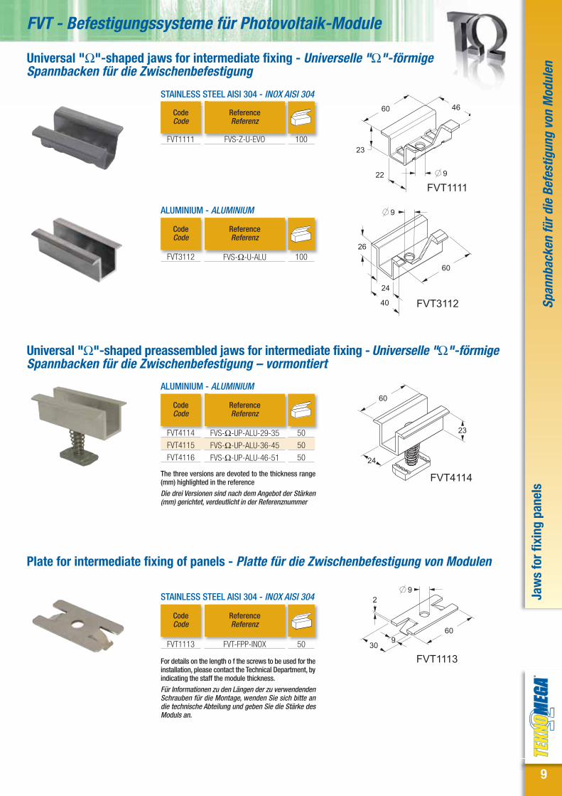
Universal "Ω"-shaped jaws for intermediate fixing - Universelle "Ω"-förmigeSpannbacken für die Zwischenbefestigung
STAINLESS STEEL AISI 304 - INOX AISI 304
Plate for intermediate fixing of panels - Platte für die Zwischenbefestigung von Modulen
The three versions are devoted to the thickness range(mm) highlighted in the reference
Die drei Versionen sind nach dem Angebot der Stärken(mm) gerichtet, verdeutlicht in der Referenznummer
ReferenceReferenz
CodeCode
ReferenceReferenz
CodeCode
ReferenceReferenz
CodeCode
FVT1113 FVT-FPP-INOX 50
FVT3112 FVS-Ω-U-ALU 100
FVT1111 FVS-Z-U-EVO 100
FVT311224
26
9
40
60
ALUMINIUM - ALUMINIUM
ReferenceReferenz
CodeCode
FVT4114
FVT4115
FVT4116
FVS-Ω-UP-ALU-29-35
FVS-Ω-UP-ALU-36-45
FVS-Ω-UP-ALU-46-51
50
50
50
FVT4114
24
23
60
FVT11119
46
22
23
60
Universal "Ω"-shaped preassembled jaws for intermediate fixing - Universelle "Ω"-förmigeSpannbacken für die Zwischenbefestigung – vormontiert
For details on the length o f the screws to be used for theinstallation, please contact the Technical Department, byindicating the staff the module thickness.
Für Informationen zu den Längen der zu verwendendenSchrauben für die Montage, wenden Sie sich bitte andie technische Abteilung und geben Sie die Stärke desModuls an.

10
Stee
l bra
cket
s fo
r slo
ping
roof
sSt
ahlh
alte
rung
für S
chrä
gdäc
her
FVT - Fixing for photovoltaic panels
ReferenceReferenz
CodeCode A mm B mm
FOR FIXING ON CONCRETE - FÜR DIE BEFESTIGUNG AUF BETON
“S”-type bracket - Halterung Typ „S“
“S”-type adjustable bracket - Halterung Typ „S“
F
Z
Z
Z
Z
Z
Z
ReferenceReferenz
CodeCode A mm B mm
FOR FIXING ON WOOD - FÜR DIE BEFESTIGUNG AUF HOLZ
“P”-type bracket - Halterung Typ "P"
ReferenceReferenz
CodeCode
Adjustment mmRegulierung mm F
FVT1120
11x25
11x25
11
3085
60 B
A
213
FVT1240
11x25
11x25
124
213
115-160
30
11
FVT1246
11x25
124
220
35
-149111
11
FVT1180
11x25
A
B
80140217.5
(8X)11
FVT1180
FVT1185
FVT1190
FVT1195
FVT1200
FVT1205
FVS-P-105-ZC
FVS-P-110-ZC
FVS-P-115-ZC
FVS-P-120-ZC
FVS-P-125-ZC
FVS-P-130-ZC
31
36
41
46
51
56
115
120
125
130
135
140
F
Z
Z
Z
Z
Z
Z
FVT1240
FVT1246
FVS-S-RGL-ZC
FVS-S-RGL-EVO
From 115 to 160
Von 115 bis 160
From 111 to 149
Von 111 bis 149
Z
SS
FVT1120
FVT1125
FVT1130
FVT1135
FVT1140
FVT1145
FVS-S-105-ZC
FVS-S-110-ZC
FVS-S-115-ZC
FVS-S-120-ZC
FVS-S-125-ZC
FVS-S-130-ZC
31
36
41
46
51
56
115
120
125
130
135
140
16
16
16
16
16
16
16
16
12
12
12
12
12
12
Inverting the central “Z”-shaped part of the FVT1246 bracket, you get thefollowing different adjustments: mm 111/143 or mm 124/149
Bei Halterung FVT1246 erhält man durch das Umdrehen des zentralen“z”- förmigen Teils verschiedene Regulierungen, wie folgt: mm 111/143oder auch mm 124/149
FOR FIXING ON CONCRETE - FÜR DIE BEFESTIGUNG AUF BETON

11
Stee
l bra
cket
s fo
r slo
ping
roof
sSt
ahlh
alte
rung
für S
chrä
gdäc
her
FVT - Befestigungssysteme für Photovoltaik-Module
Adjustable “P”-type bracket - Verstellbare Halterung Typ "P"
ReferenceReferenz
CodeCode
Adjustment mmRegulierung mm
FOR FIXING ON WOOD - FÜR DIE BEFESTIGUNG AUF HOLZ
F
Adjustable “C”-type bracket - Verstellbare Halterung Typ "C"
ReferenceReferenz
CodeCode
Adjustment mmRegulierung mm F
FVT1250
140 55 179
115-16030
(8X)11
FVT1256
11x25
13074
-149111
198.5
11
11x25
11x25
30 220
6078- 101
11
FVT1260
FVT1260
FVT1265
FVS-C-RGL-ZC
FVS-C-RGL-INOX
From 78 to 101
Von 78 bis 101
From 78 to 101
Von 78 bis 101
Z
SS
FVT1250
FVT1256
FVS-P-RGL-ZC
FVS-P-RGL-EVO
From 115 to 160
Von 115 bis 160
From 111 to 149
Von 111 bis 149
Z
SS
12
16
20
20
Adjustable “R”-type bracket - Verstellbare Halterung Typ "R"
ReferenceReferenz
CodeCode
Adjustment mmRegulierung mm
FOR FIXING ON CONCRETE - FÜR DIE BEFESTIGUNG AUF BETON
F
FVT1267
11x25
30
200
187- 207
104- 124
11FVT1267 FVS-R-RGL-INOX From 187 to 207
Von 187 bis 207
SS 8
Inverting the central “Z”-shaped part of the FVT1256 bracket, you get thefollowing different adjustments: mm 111/143 or mm 124/149
Bei der Halterung FVT1256 erhält man durch das Umdrehen des zentralen“z”- förmigen Teils verschiedene Regulierungen, wie folgt: mm 111/143oder auch mm 124/149
FOR FIXING ON CONCRETE - FÜR DIE BEFESTIGUNG AUF BETON

12
Fixi
ng s
olut
ions
for m
etal
dec
king
Lösu
ngen
für d
ie B
efes
tigun
g au
f Tra
pezb
lech
FVT - Fixing for photovoltaic panels
Stainless steel bracket upon drawing - Edelstahlhalterungnach Zeichnung
Self-drilling and self-threading screws for metal decking brackets - Selbstbohrende – selbstschneidende Schrauben für Halterungen auf Trapezblech
ReferenceReferenz
CodeCode A B H F
ReferenceReferenz
CodeCode M F
For manufacturing the bracket, it’s always necessary to indicate thedimensions of the metal decking. We suggest using the neoprene orbutyl rubber gasket (see page 21)
Für die Herstellung der Halterungen ist es notwendig, immer die Maßeder Wellbleche anzugeben. Es wird die Verwendung von Neopren-oder Butyldichtungen (siehe Seite 21) empfohlen
EPDM gaskets included)
Komplett mit Dichtungen aus EPDM
ReferenceReferenz
CodeCode F
Nuts and screws TE M8x16 included – max. wrenchtorque 40N/m
Komplett mit Muttern und Schrauben TE M8x16-Anzugsmoment max. 40 N/m
FVT95XX
AB
H
120
7
FVT96XXA
B120
7
H
FVT1545
FVT1299M8x16
11x20
11x30
100
50
35
FVT1299 FVT-SLG-MRS-INOX SS 10
FVT1545 FVT-VLG-6x25-INOX 6 SS 100
FVT95XX
FVT96XX
FVT-SLG-R
FVT-SLG-P
SS
SS
SR
SR
SR
SR
SR
SR
INSTALLATION EXAMPLES - MONTAGEBEISPIEL
Stainless steel clamp - Klemme Inox

13
Fixi
ng s
olut
ions
for m
etal
dec
king
Lösu
ngen
für d
ie B
efes
tigun
g au
f Tra
pezb
lech
FVT - Befestigungssysteme für Photovoltaik-Module
FVT5000
A
B
L
Universal kits for metal decking and sandwich panel - Universal- Kit fürTrapezblech und Sandwich- Paneel
Side spacer - Seiten Distanzstück
ReferenceReferenz
CodeCode A mm B mm L mm
FVT5000
FVT50XX
FVT-SLG-UO80-INOX
Fixing template
Bohrschablone
20
1
63 23 80
F
SS
S
PREASSEMBLED KIT FOR FIXING A HORIZONTAL MODULE - VOTMONTIERTES KITFÜR DIE BEFESIGUNG EINES HORITONALEN MODULS
Please provide the panel width
Geben Sie die Breite des Paneels an
FVT5005
IB
L AReferenceReferenz
CodeCode A mm B mm L mm
FVT5005
FVT5010
FVT-SLG-UV280-INOX
FVT-SLG-UV400-INOX
10
10
63
63
23
23
280
400
I mm
110-250
250-330
F
SS
SS
PREASSEMBLED KIT FOR FIXING A VERTICAL MODULE - VOTMONTIERTES KIT FÜRDIE BEFESIGUNG EINES VERTIKALEN MODULS
ReferenceReferenz
CodeCode A mm Th. mm
Stärke mm
FVT5030
FVT5033
FVT5036
FVT5038
FVT5041
FVT5043
FVT5046
FVT5048
FVT5051
FVS-UP-30-INOX
FVS-UP-33-INOX
FVS-UP-36-INOX
FVS-UP-38-INOX
FVS-UP-41-INOX
FVS-UP-43-INOX
FVS-UP-46-INOX
FVS-UP-48-INOX
FVS-UP-51-INOX
20
20
20
20
20
20
20
20
20
30
33
36
38
41
43
46
48
51
29-30-31
32-33-34
35-36
37-38-39
40-41
42-43-44
45-46
47-48-49
50-51
STAINLESS STEEL 304 - INOX AISI 304
INSTALLATION EXAMPLES - MONTAGEBEISPIEL
FVT5041
For tightening the bracket, please use the sleeve wrench type Beta series 900L 13 mm or a sleevewrench, type Usag code 235543 of 13 mm
Für der Befestigung der Halterungen werden Inbussschlüssel des Typs Beta Serie 900L oder einInbussschlüssel des Typs Usag Code 235543 von 13 mm verwendet
Under patent request - Patentanmeldung

14
FVT - Fixing for photovoltaic panelsFi
sol
utio
ns fo
r met
al d
ecki
ngLö
sung
en fü
r die
Bef
estig
ung
auf T
rape
zble
ch
Double thread mill screws with EPDM gasket - Doppelgewindeschrauben mit EPDM- Dichtung
ReferenceReferenz M A
FIXING ON WOOD OR CONCRETE - BEFESTIGUNG AUF HOLZ ODER BETON
B L F
Nuts-washers- gaskets included for use on concrete used on a suitable shim
Muttern – Unterlegscheiben – Dichtungen inklusive; für Verwendung auf Beton einengeeigneten Dübel verwenden
CodeCode
ReferenceReferenz M1 M2
METAL FIXING - BEFESTIGUNG AUF METALL
A B F
Nuts-washers- gaskets included
Muttern – Unterlegscheiben – Dichtungen inklusive
CodeCode
ReferenceReferenz
FIXING PLATE - BEFESTIGUNGSPLATTE
CodeCode
Ø mm pre-hole for fixing on metalØ mm Vorbohrung für Befestigung
auf Metall
Structure th. (mm)Stärke der Struktur
(mm)
Pre-hole (mm)Vorbohrung
(mm)
FVT1515 FVT-P2-SS 501,5 ≤ 5,0
5,0 ≤ 7,5
7,5 ≤ 10
≥ 10
6,8
7
7,2
7,4
FVT1317
FVT1318
FVT1319
FVA-AF-80-50M10-INOX
FVA-AF-100-50M10-INOX
FVA-AF-150-50M10-INOX
50
50
50
10
10
10
8
8
8
SS
SS
SS
80
100
150
25
25
25
FVT1300
FVT1305
FVT1310
FVT1315
FVT1316
FVA-AF-10X200-INOX
FVA-AF-10X250-INOX
FVA-AF-12X250-INOX
FVA-AF-12X300-INOX
FVA-AF-12X350-INOX
200
250
250
300
350
10
10
12
12
12
67
67
100
100
100
SS
SS
SS
SS
SS
110
125
120
170
215
50
50
50
50
50
FVT1515
11x404
4080
13
FVT1305
FVT1325
FVT1515
FVT1001
PRF1225
FVT1305
INSTALLATION EXAMPLES - MONTAGEBEISPIEL
15
Fixi
ng s
olut
ions
for f
lat r
oofs
Lösu
ngen
für d
ie B
efes
tigun
g au
f ein
em F
lach
dach
FVT - Befestigungssysteme für Photovoltaik-Module
FVT2511
299.4
1660
50
FVT2512990
50300.8
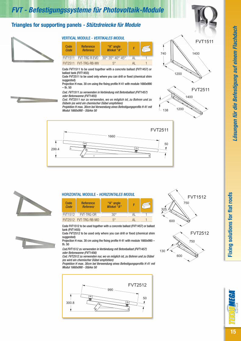
Triangles for supporting panels - Stützdreiecke für Module
ReferenceReferenz
CodeCode
“A” angleWinkel "A"
HORIZONTAL MODULE - HORIZONTALES MODUL
F
FVT1511
1200
1400740
FVT2511
1200138
1400
FVT1512
600
750
325
FVT2512
600
750
130
ReferenceReferenz
CodeCode
“A” angleWinkel "A"
VERTICAL MODULE - VERTIKALES MODUL
F
Code FVT1511 to be used together with a concrete ballast (FVT1457) orballast tank (FVT1455)Code FVT2511 to be used only where you can drill or fixed (chemical shimsuggested)Projection H max. 30 cm using the fixing profile H 41 with module 1660x990– th. 50
Cod. FVT1511 zu verwenden in Verbindung mit Betonballast (FVT1457)oder Betonwanne (FVT1455)Cod. FVT2511 nur zu verwenden, wo es möglich ist, zu Bohren und zuDübeln (es wird ein chemischer Dübel empfohlen)Projektion H max. 30cm bei Verwendung eines Befestigungsprofils H 41 mitModul 1660x990 - Stärke 50
Code FVT1512 to be used together with a concrete ballast (FVT1457) or ballasttank (FVT1455)Code FVT2512 to be used only where you can drill or fixed (chemical shimsuggested)Projection H max. 30 cm using the fixing profile H 41 with module 1660x990 –th. 50
Cod.FVT1512 zu verwenden in Verbindung mit Betonballast (FVT1457)oder Betonwanne (FVT1456)Cod. FVT2512 zu verwenden nur, wo es möglich ist, zu Bohren und zu Dübel(es wird ein chemischer Dübel empfohlen)Projektion H max. 30cm bei Verwendung eines Befestigungsprofils H 41 mitModul 1660x990 - Stärke 50
FVT1512
FVT2512
FVT-TRG-OR
FVT-TRG-RB-MO
30°
5°
AL
AL
FVT1511
FVT2511
FVT-TRG-R-EVO
FVT-TRG-RB-MV
30°-35°-40°-45°
5°
AL
AL
1
1
1
1

16
Fixi
ng s
olut
ions
for f
lat r
oofs
Lösu
ngen
für d
ie B
efes
tigun
g au
f ein
em F
lach
dach
FVT - Fixing for photovoltaic panels
Available only with different tilting, upon request
Auf Anfrage mit verschiedenen Winkeln erhältlich
Available only with different tilting, upon request
Auf Anfrage mit verschiedenen Winkeln erhältlich
ReferenceReferenz
CodeCode
“A” angleWinkel "A"
VERTICAL MODULE - VERTIKALES MODUL
F
To be used only where you can drill or fixed (chemical shim suggested)
Nur zu verwenden , wo es möglich ist, zu Bohren und zu Dübeln(es wird ein chemischer Dübel empfohlen)
FVT1513
1000300
7501100
FVT1513 FVT-TRG-RR 25-30° AL 1
ReferenceReferenz
CodeCode
“A” angleWinkel "A"
FOR TWO VERTICAL MODULES - FÜR ZWEI VERTIKALE MODULE
F
FVT1514
2430
1680
300
2800FVT1514 FVT-TRG-DP 30° AL 1
Double triangle - Doppeldreieck
ReferenceReferenz
CodeCode
“A” angleWinkel "A"
FOR TWO HORIZONTAL MODULES - FÜR ZWEI HORIZONTALEMODULE
FFVT1517
1670
1850890FVT1517 FVT-TRG-DP-O 30° AL 1
Triangles for supporting panels - Stützdreieck für Module
INSTALLATION EXAMPLES - MONTAGEBEISPIEL
FVT1517FVT1514

17
Fixi
ng s
olut
ions
for f
lat r
oofs
Lösu
ngen
für d
ie B
efes
tigun
g au
f ein
em F
lach
dach
FVT - Befestigungssysteme für Photovoltaik-Module
Wind rod for triangles - Verstrebungen für Dreiecke
ReferenceReferenz
CodeCode F
FVT1285
FVT1286
FVT1287
FVT-SCV-ZC
FVT-SCV-ALU
FVTSCV-S-ALU
ZC
ALU
ALU
Center distance mtAchsabstand mt
1,5
1,5
1Upon request, Alu wind rods according to specific length For fixing totriangles, we suggest the screws TE M10x20 (code FVT1325)
Auf Anfrage Aluminiumverstrebungen mit spezifischer Länge Für die Befestigung von Dreiecken werden die Schrauben TE M10x20 (Cod.FVT1325) empfohlen
I
10
10
10
Ballast tanks - Betonwannen
ReferenceReferenz
CodeCode
Volume (m3)Volumen (m³) FWeight Kg
Gewicht kg
Concrete Ballasts - Betonballast
ReferenceReferenz
CodeCode
Weight KgGewicht kg
Threaded bars and fixing nuts M10 STAINLESS STEEL AISI 304 included *For triangle fixing the horizontal module FVT1512 - Weight of the tank filled with concrete
Inklusive Gewindestangen und Befestigungsmuttern M10 INOX AISI 304 * Für Dreiecke zur Befestigung von horizontalen Modulen FVT1512 Relatives Gewicht zuder mit Zement gefüllten Wanne
With thread inserts M10 - For applications on ballasts,see page 28 and page 29
Mit Gewindeeinsätzen M10Für die Anwendungen von Ballast siehe Seite 28 undSeite 29
With thread inserts M10 - Bracket and fixing screwsand nuts included - Max. H projection 30 cm using thefixing profile H 41 with module 1660x990, TH. 50 - Forinstallation instructions, see the technical chapter
Mit Gewindeeinsätzen M10 - Inklusive Halterung undBefestigungsschrauben - Projektion H max. 30cm beiVerwendung von Befestigungsprofilen H 41 mit Modul1660x990 - Stärke 50 - Für die Montageanleitung siehetechnisches Kapitel
FVT1455
150
350
1300
FVT1456
140
350700
FVT1457195
200
465
FVT1465
495
120
FVT1457
FVT1465
FVV-ZVC
FVV-ZVC-1002
40
14
FVT1455
FVT1456*
FVV-VSC-SDZ
FVV-VSC-SDZ-OR
0,06
0,03
S+V
S+V
120
60
1
1
1
1
ReferenceReferenz
CodeCode
FLAT SYSTEM - SYSTEM FLAT
Weight KgGewicht kg
FVT1458
480190
FVT1459
480190
FVT1458
FVT1459
FVV-ZVC-30-1
FVV-ZVC-30-2
33
18
1
1
1660
50
295

18
FVT - Fixing for photovoltaic panels
STF1050150150
19
114114
100
FVT1270
304560
0-909
11x15
132
9347.5
ANGULAR BRACKETS AT 90° - 2 HOLES - 90° WINKELBÜGEL - 2 BOHRUNGEN
ReferenceReferenz
CodeCode
ReferenceReferenz
CodeCode
ReferenceReferenz
CodeCode
ReferenceReferenz
CodeCode
“OMEGA”-SHAPED BRACKETS - "OMEGA" - FÖRMIGER BÜGEL
ARROW-SHAPED REINFORCING BRACKET - SPITZERVERSTÄRKUNGSBÜGEL
Hot galvanizes – Thickness 6 mm – Holes diameter 14 mm - Feuerverzinkt - Stärke 6 mm– Durchmesser der Bohrungen 14 mm
STF1025
STF1030
STF1035
STF-041
STF-021
STF-82
10
10
10
FVT1270 FVS-AV-ZC 10
STF1140
300300
ReferenceReferenz
CodeCode
STF1140 STF-SR300 10
STF1050 STF-B41 10
STF1100 STF-W45 10
ReferenceReferenz
CodeCode
STF1105
STF1110
STF1115
STF1120
STF-WL2
STF-WL3
STF-WL4
STF-WL4R
10
10
10
10STF1105
48
50
STF1100
45
75
58
ReferenceReferenz
CodeCode
STF1101
STF1102
STF-W30A
STF-W30-90A
10
10STF1101
60
130
130
STF1102
60
100
100
75
STF1110
98
47
STF1115
102
86
STF102540
137
STF103040
137
STF103540
137
STF112087
102
Ω S
TRUT
- S
teel
bra
cket
s fo
r STR
UT p
rofil
eΩ
STR
UT -
Sta
hlha
lteru
ngen
für S
TRUT
- Pr
ofile
BRACKET AT 45° - 45° WINKELBÜGEL
BRACKET AT 30° - 30° WINKELBÜGEL
BASIC PLATE FOR BRACKET - BASISPLATTENBÜGEL
BRACKET WITH ADJUSTABLE ANGLE - BÜGEL MIT VERSTELLBAREM WINKEL

19
Met
al s
crew
s an
d nu
tsSc
hrau
ben
und
Met
allk
lein
teile
FVT - Befestigungssysteme für Photovoltaik-Module
STRUT nuts with spring - STRUT- Muttern mit Feder
ReferenceReferenz
CodeCode
HOT GALVANIZED - FEUERVERZINK
M
Head hammer screw - HammerkopfschraubeHOT GALVANIZED - FEUERVERZINK
STAINLESS STEEL 304 - INOX AISI 304
ReferenceReferenz
CodeCode MxH
ReferenceReferenz
CodeCode MxH
Screw kit TCEI with spring - Schrauben- Kit TCEI mit Unterlegscheibe
FVT1330
FVT1332
FVT1335
FVT1337
FVT1340
FVT1342
FVT1344
FVT1345
FVT1346
FVT1350
FVT1355
FVA-TCEI-8x10-INOX
FVA-TCEI-8x20-INOX
FVA-TCEI-8x25-INOX
FVA-TCEI-8x30-INOX
FVA-TCEI-8x40-INOX
FVA-TCEI-8x50-INOX
FVA-TCEI-8x70-INOX
FVA-TCEI-10x25-INOX
FVA-TCEI-10x20-INOX
FVA-TCEI-10x40-INOX
FVA-TCEI-10X50-INOX
M8x10
M8x20
M8x25
M8x30
M8x40
M8x50
M8x70
M10x25
M10x20
M10x40
M10X50
FVT1395
FVT1400
FVA-TM-8X30-ZC
FVA-TM-10X30-ZC
M8x30
M10x30
DAP2000
DAP2005
DAP2010
DAP2020
DAP2025
DAP2030
DAP2040
DAP2045
DAP2050
DAP-M6-S-ZC
DAP-M8-S-ZC
DAP-M10-S-ZC
DAP-M6-C-ZC
FVA-M8-C-ZC
FVA-M10-C-ZC
FVA-M6-L-ZC
FVA-M8-L-ZC
FVA-M10-L-ZC
STAINLESS STEEL 304 - INOX AISI 304
M6
M8
M10
M6
M8
M10
M6
M8
M10
DAP3005
DAP3010
DAP3025
DAP3030
DAP3045
DAP3050
FVA-M8-S-SS
FVA-M10-S-SS
FVA-M8-C-SS
FVA-M10-C-SS
FVA-M8-L-SS
FVA-M10-L-SS
100
100
100
100
100
100
M8
M10
M8
M10
M8
M10
100
100
100
100
100
100
100
100
100
100
100
100
100
100
100
100
100
100
100
100
100
100
S
6
2036
M
C
L
FVT1400
Screw kit TE with nut and washer - Schrauben- Kit TE mit Mutter und UnterlegscheibeSTAINLESS STEEL 304 - INOX AISI 304
ReferenceReferenz
CodeCode MxH
FVT1320
FVT1325
FVA-TE-8x16-INOX
FVA-TE-10x20-INOX
M8x16
M10x20
100
100
20
Met
al s
crew
s an
d nu
tsSc
hrau
ben
und
Met
allk
lein
teile
FVT - Fixing for photovoltaic panels
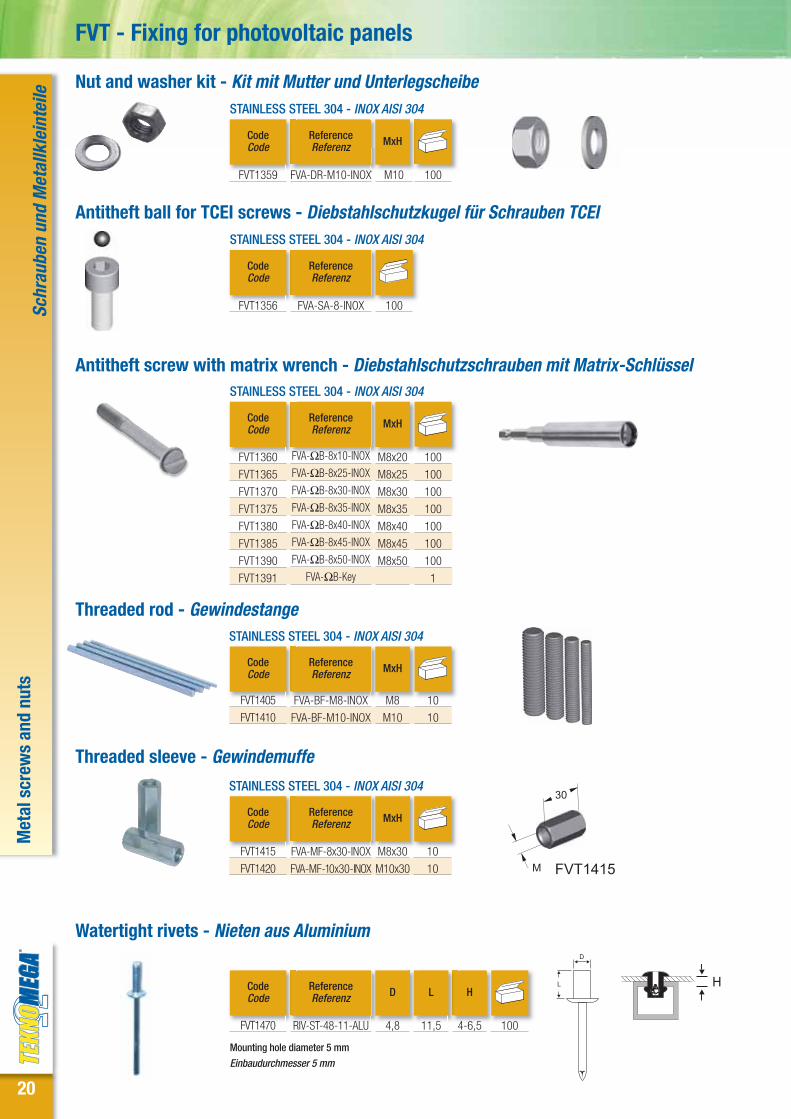
Antitheft ball for TCEI screws - Diebstahlschutzkugel für Schrauben TCEI
ReferenceReferenz
CodeCode
STAINLESS STEEL 304 - INOX AISI 304
FVT1356 FVA-SA-8-INOX 100
Nut and washer kit - Kit mit Mutter und Unterlegscheibe
ReferenceReferenz
CodeCode
STAINLESS STEEL 304 - INOX AISI 304
FVT1359 FVA-DR-M10-INOX 100
Threaded rod - GewindestangeSTAINLESS STEEL 304 - INOX AISI 304
ReferenceReferenz
CodeCode MxH
Threaded sleeve - GewindemuffeSTAINLESS STEEL 304 - INOX AISI 304
ReferenceReferenz
CodeCode MxH
FVT1415
FVT1420
FVA-MF-8x30-INOX
FVA-MF-10x30-INOX
M8x30
M10x30
FVT1405
FVT1410
FVA-BF-M8-INOX
FVA-BF-M10-INOX
M8
M10
FVT1415M
30
10
10
10
10
Watertight rivets - Nieten aus Aluminium
ReferenceReferenz
CodeCode D
FVT1470 RIV-ST-48-11-ALU 4,8
H
4-6,5
L
11,5 100
Antitheft screw with matrix wrench - Diebstahlschutzschrauben mit Matrix-SchlüsselSTAINLESS STEEL 304 - INOX AISI 304
ReferenceReferenz
CodeCode MxH
MxH
FVT1360
FVT1365
FVT1370
FVT1375
FVT1380
FVT1385
FVT1390
FVT1391
FVA-ΩB-8x10-INOX
FVA-ΩB-8x25-INOX
FVA-ΩB-8x30-INOX
FVA-ΩB-8x35-INOX
FVA-ΩB-8x40-INOX
FVA-ΩB-8x45-INOX
FVA-ΩB-8x50-INOX
FVA-ΩB-Key
M8x20
M8x25
M8x30
M8x35
M8x40
M8x45
M8x50
100
100
100
100
100
100
100
1
H
Mounting hole diameter 5 mm
Einbaudurchmesser 5 mm
M10

21
Plastic caps for STRUT profiles - Plastikklappen für Profile STRUT
Neoprene gaskets in rolls - Neoprendichtungen in Rollen
ReferenceReferenz
CodeCode
Dimensions mmMaße mm
FVT1530
FVT1535
FVT1540
FVT-GN-120
FVT-GN-80
FVT-GN-7
120x3 (x10 mt)
80x3 (x10 mt)
7x2 (x 20 mt)
Butyl and bituminous gaskets - Butyl-Dichtungen und bitumenhaltige Dichtungen
ReferenceReferenz
MaterialMaterial
CodeCode
Dimensions mmMaße mm
FVT1550
FVT1551
FVT1552
FVT1555
FVT1560
FVT-GBU-50
FVT-GBU-10
FVT-GBU-120
FVT-MBI-1000
FVT-MBI-K
1
1
1
1
1
Netted butyl tape
Netz- Butylband
Netted butyl tape
Netz- Butylband
Netted butyl tape
Netz- Butylband
Bituminous membrane
Bitumenhaltige Membran
Bituminous mastic
Bituminös Kitt
UseVerwendung
Under brackets and profiles
Unter Halterungen und Profile
Under brackets and profiles
Unter Halterungen und Profilei
Under brackets and profiles
Unter Halterungen und Profile
Roof waterproofing
Imprägnierung Dächer
Waterproofing
Imprägnierung
50x1,5 (x10 mt)
10x1,5 (x10 mt)
120x1,5 (x10 mt)
1000x1,2(x25 mt)
Cartridge
Kartusche Acce
ssor
ies
Zube
hör
FVT - Befestigungssysteme für Photovoltaik-Module
UseVerwendung
1
1
1
Brackets for metal docking
Halterungen x Wellblech
Brackets for metal docking
Halterungen x Wellblech
Z-shaped and aluminium Ω-shapedbrackets
Halterungen Z-Förmig und Ω-Förmig aus Aluminium
ReferenceReferenz
CodeCode
BUL1020
BUL1025
BUL-TP21
BUL-TP41
100
100
The code FVT1555 has an upper coating made of antislip material
Der Code FVT1555 besitzt eine obere Abdeckung aus rutschfestem Aluminium

22
Acce
ssor
ies
Zube
hör
FVT - Fixing for photovoltaic panels
Guide for choosing the TCEI bolts - Anleitung zum Auswählen der Metallkleinteile TCEI
CodeCode
Profile code - Code Profilschiene
Panel Thickness (mm) - Stärke des Paneels (mm)
FVT1040
FVT1045
FVT1050
FVT1055
FVT1060
FVT1065
FVT1066
FVT1070
FVT1075
FVT1080
FVT3031
FVT3034
FVT3036
FVT3039
FVT3041
FVT3044
FVT3046
FVT3049
FVT3051
FVT1111
M8X30
M10X40
29-30-31 32-33-34 35-36 37-38-39 40-41
M8X50
M8X50
42-43-44
M8X50
M8X50
45-46
M8X50
M8X50
47-48-49
FVT3112
50-51CodeCode
M8X25
M10X25
M8X30
M10X40
M8X30
M10X40
M8X40
M10X40
M8X40
M10X40
M8X40
M10X40
M8X40
M10X40
M8X50
M8X50
M8X25
M10X25
M8X30
M10X40
M8X30
M10X40
M8X40
M10X40
M8X40
M10X40
M8X40
M10X40
M8X40
M10X40
M8X50
M8X50
M8X25
M10X25
M8X30
M10X40
M8X30
M10X40
M8X40
M10X40
M8X40
M10X40
M8X40
M10X40
M8X40
M10X40
M8X50
M8X50
M8X25
M10X25
M8X30
M10X40
M8X30
M10X40
M8X40
M10X40
M8X40
M10X40
M8X40
M10X40
M8X40
M10X40
M8X50
M8X50
M8X25
M10X25
M8X30
M10X40
M8X30
M10X40
M8X40
M10X40
M8X40
M10X40
M8X40
M10X40
M8X40
M10X40
M8X50
M8X50
M8X25
M10X25
M8X30
M10X40
M8X30
M10X40
M8X40
M10X40
M8X40
M10X40
M8X40
M10X40
M8X40
M10X40
M8X50
M8X50
M8X25
M10X25
M8X30
M10X40
M8X30
M10X40
M8X40
M10X40
M8X40
M10X40
M8X40
M10X40
M8X40
M10X40
M8X50
M8X50
M8X25
M10X25
M8X30
M10X40
M8X30
M10X40
M8X40
M10X40
M8X40
M10X40
M8X40
M10X40
M8X40
M10X40
M8X50
M8X50
M8X25
M10X25
M8X30
M10X40
M8X30
M10X40
M8X40
M10X40
M8X40
M10X40
M8X40
M10X40
M8X40
M10X40
M8X50
M8X50
M8X25
M10X25
M8X30
M10X40
M8X30
M10X40
M8X40
M10X40
M8X40
M10X40
M8X40
M10X40
M8X40
M10X40
M8X50
M8X50
M8X25
M10X25
M8X30
M10X40
M8X30
M10X40
M8X40
M10X40
M8X40
M10X40
M8X40
M10X40
M8X40
M10X40
M8X50
M8X50
M8X25
M10X25
M8X30
M10X40
M8X30
M10X40
M8X40
M10X40
M8X40
M10X40
M8X40
M10X40
M8X40
M10X40
M8X50
M8X50
M8X50
M8X50
Log spring nut
Mutter mit langer Feder Short spring nut
Mutter mit kurzer Feder
M8X40
M10X40
M8X40
M10X40
M8X40
M10X40
M8X40
M10X40
M8X40
M10X40
M8X40
M10X40
M8X40
M10X40
M8X40
M10X40
FVT1000 FVT1001 FVT1005 FVT1006 FVT1010 FVT1015 PRF1145 PRF1150 PRF1225 PRF1230 PRF9004 PRF9000
M8X20
M10X25
M8X20
M10X25
M8X20
M10X25
M8X20
M10X25
M8X20
M10X25
M8X20
M10X25
M8X20
M10X25
M8X20
M10X25
M8X20
M10X25
M8X20
M10X25
M8X20
M10X25
M8X20
M10X25
M8X20
M10X25
M8X20
M10X25
M8X20
M10X25
M8X20
M10X25
M8X20
M10X25
M8X20
M10X25
M8X20
M10X25
M8X20
M10X25
M8X20
M10X25
M8X20
M10X25
M8X20
M10X25
M8X20
M10X25
M8X20
M10X25
M8X20
M10X25
M8X20
M10X25
M8X20
M10X25
M8X20
M10X25
M8X20
M10X25
M8X20
M10X25
M8X20
M10X25
M8X20
M10X25
M8X20
M10X25
M8X20
M10X25
M8X20
M10X25
M8X20
M10X25
M8X20
M10X25
M8X20
M10X25
M8X20
M10X25
M8X20
M10X25
M8X20
M10X25
M8X20
M10X25
M8X20
M10X25
M8X20
M10X25
M8X20
M10X25
M8X20
M10X25
M8X20
M10X25
M8X20
M10X25
M8X20
M10X25
M8X20
M10X25
M8X20
M10X25
M8X20
M10X25
M8X20
M10X25
M8X20
M10X25
M8X20
M10X25
M8X20
M10X25
M8X20
M10X25
M8X20
M10X25
M8X20
M10X25
M8X20
M10X25
M8X20
M10X25
M8X20
M10X25
M8X20
M10X25
M8X20
M10X25
M8X20
M10X25
M8X20
M10X25
M8X20
M10X25
M8X20
M10X25
M8X20
M10X25
M8X20
M10X25
M8X20
M10X25
M8X20
M10X25
M8X20
M10X25
M8X20
M10X25
M8X20
M10X25
M8X20
M10X25
M8X20
M10X25
M8X20
M10X25
M8X20
M10X25
M8X20
M10X25
M8X20
M10X25
M8X20
M10X25
M8X20
M10X25
M8X20
M10X25
M8X20
M10X25
M8X20
M10X25
M8X20
M10X25
M8X20
M10X25
M8X20
M10X25
M8X20
M10X25
M8X20
M10X25
M8X20
M10X25
M8X20
M10X25
M8X20
M10X25
M8X20
M10X25
M8X20
M10X25
M8X20
M10X25
M8X20
M10X25
M8X20
M10X25
M8X20
M10X25
M8X20
M10X25
M8X20
M10X25
M8X20
M10X25
M8X20
M10X25
M8X20
M10X25
M8X20
M10X25
M8X20
M10X25
M8X20
M10X25
M8X20
M10X25
M8X20
M10X25
M8X20
M10X25
M8X20
M10X25
M8X20
M10X25
M8X20
M10X25
M8X20
M10X25
M8X20
M10X25
M8X20
M10X25
M8X20
M10X25
M8X20
M10X25

23
FVT - Befestigungssysteme für Photovoltaik-Module
TECHNICAL FEATURES - TECHNISCHE DATEN
Conductor - LeiterProved and tested for uses up to 1000 V DC Quick clutch on DIN guidedGeprüft und zertifiziert für Anwendungen bis zu 1000V DC Schnellkupplung auf den DIN-Schienen Screws included lcw according to the standard IEC 947-7-1Inklusive Schrauben Icw nach IEC 947-7-1 StandardInsulating protection between the phases RPB1005: right or left inletsSchutzisolierung zwischen den Phasen RPB1005: Eingänge links oder rechtsInsulating self-extinguishing structure: UL 94V0Selbstverlöschende isolierendes Gehäuse: UL 94V0
BIPOLAR 125A - BIPOLAR 125A
CodeCode
RPB1005
ReferenceReferenz
RPB 125-14
Weight KgGewicht kg
0,206
L
132
H
45
P
50
Center distance between thefixing holes mm
Lochabstand festgelegt mm
110 1
S.p.A.DIVISIONE PROVE E MISURE
RAPPORTO DI PROVA
RP 09-0554 Rev. 00 Pag. 12 di 13
- Tabella 05: VERIFICA DELLA TENUTA DI RIGIDITÀ A FREQUENZA DI ESERCIZIO
Secondo tabella12A EN 60947-1
Tensione diisolamentonominale Ui
[V]
Tensione perprova dielettrica
[Vac]
Esito
NoteTra parti attive didifferente polarità
Tra parti attive didifferente polarità e
l’involucro ricoperto daun foglio di Alluminio
800< Ui 1000 2200 Conforme Conforme Non si verificano scarichedopo 1 minuto
Electrical components - Elektrische Komponenten
TECNICAL TABLES - TECHNISCHE TABELLEN
CodeCode
RPB1005
Ipk kA
20
UY
20
IN/OUT
IN →IN - OUT↔← OUT
← OUT
Cable mm2
Kabel mm²
10 ÷ 35
10 ÷ 35
2,5 ÷ 6
10 ÷ 25
Tip mm²Spitze mm²
10 ÷ 25
10 ÷ 25
1,5 ÷ 6
6 ÷1 6
N°
1
1
11
2
Ø mm
9,0
9,0
5,5
7,5
Wrench torque NmAnziehdrehmoment Nm
2 - 3
2 - 3
2 - 3
2 -3
Icw kA rms 1s
4,2
The bipolar terminal board RPB1005 is proven and tested for the use in DC and is an excellent solution for connecting the string cables
Die bipolare Klemmleiste RPB1005 -geprüft und zertifiziert- für die Verwendung bei Gleichstrom ist eine optimale Lösung zum Zusammenfassen von Strangleitungen
Ω B
LOCK
Spl
itter
with
term
inal
boa
rdΩ
BLO
CK V
erte
iler-
Kle
mm
leis
te

24
Test
repo
rts
Prüf
beric
hte
FVT - Fixing for photovoltaic panels
The test reports contained in the catalogue are available upon request
Die im Katalog enthaltenden Prüfberichte sind auf Anfrage erhältlich

25
Feat
ures
of t
he m
ater
ials
Mat
eria
lspe
zifik
atio
nen
FVT - Befestigungssysteme für Photovoltaik-Module
LEGA DI ALLUMINIO DA ESTRUSIONE EN AW-6060
Caratteristiche fisiche massa volumica : 2,70 g / cm3 conducibilità
termica a 20°C - nello stato O: -nello stato T6:
2,09 1,75
W / cm °K W / cm °K
punto di fusione inferiore : 605 °C calore specifico tra 0° e 100°C: 890 J/Kg °K modulo di elasticità lineare E: 69000 N / mm2
coefficiente di dilatazione termica lineare
-tra 20° e 100°C: -tra 20° e 200°C: -tra 20° e 300°C:
23,0 10-6 24,0 10-6
25,0 10-6
1 / °K 1 / °K 1 / °K
modulo elasticità tangenziale G: 26000 N/ mm2 resistività elettrica a 20°C
-nello stato O: -nello stato T6
3,14 3,25
μΩ cm μΩ cm
Composizione chimica secondo Norma Europea EN 573.3 Altri
Si Fe Cu Mn Mg Cr Zn Ti ciascuno totale
Al
EN AW-6060
0,30 ÷
0,60
0,10 ÷
0,30
0,10 max
0,10 max
0,35 ÷
0,60
0,05 max
0,15 max
0,10 max
0,05 max
0,15 max resto
Proprietà meccaniche minime, secondo Norma Europea EN 755.2 Carico di rottura a
trazione Rm [MPa]
Carico limite di elasticità Rp0.2
[MPa]
Allungamento
Tipi
di p
rofil
o
(1) stato fisico di fornitura
dametro D [mm] per tondi, o spess. S [mm] per barre,
o spess. di parete e per profilimin max min max A %
minA50mm %
min
T4 (*) D ≤ 150 S ≤ 150 120 - 60 - 16 14
T5 D ≤ 150 S ≤ 150 160 - 120 - 8 6
T6 (*) D ≤ 150 S ≤ 150 190 - 150 - 8 6
T64 (*) D ≤ 50 S ≤ 50 180 - 120 - 12 10
Bar
re p
iene
T66 (*) D ≤ 150 S ≤ 150 215 - 160 - 8 6
41 61 - 06 - 021 )*( 4T
6 8 - 021 - 061 5T
6 8 - 051 - 091 )*( 6T
01 21 - 021 - 081 )*( 46T
Tubo
es
trus
o
T66 (*)
e ≤ 15
215 - 160 - 8 6
T4 (*) e ≤ 25 120 - 60 - 16 14
T5 e ≤ 5
5 < e < 25
160
140
-
-
120
100
-
-
8
8
6
6
T6 (*) e ≤ 3
3 < e < 25
190
170
-
-
150
140
-
-
8
8
6
6
T64 (*) e ≤ 15 180 - 120 - 12 10
Prof
ili a
pert
i e c
avi
T66 (*) e ≤ 3
3 < e < 25
215
195
-
-
160
150
-
-
8
8
6
6 NOTA ( * ) : proprietà meccaniche dello st ato fisico indicato ottenibili anche con tempra alla pressa
( 1) : vedasi Tavola relativa a: “Descrizione dei trattam enti e degli stati metallurgici adottati nella produzione standard”
La lega EN AW-6060 è la lega da estrusione più diffusa sul mercato europeo, per le sue doti di alta velocità di deformazione a caldo. Essa consente la realizzazione di profilati con sezione anche complessa, comprendente molteplici cavità e scanalature, per avvicinare quanto più possibile il disegno dell’estruso a quello del manufatto finito, e ridurre al minimo le lavorazioni intermedie.
Acciai per imbutitura e piegatura a freddo EN 10111:2008
Questi acciai sono caratterizzati da limiti massimi di snervamento e di rottura ed allungamenti minimi garantiti. Sono classificati in ordine crescente di formabilità e possono pertanto essere utilizzati nelle diverse
lavorazioni a freddo, dagli stampaggi meno critici (DD11) fino alle più profonde imbutiture (DD14).
CARATTERISTICHE MECCANICHE
Qualità Re (Mpa) Rm (Mpa) A80 (%) A5 (%) min-max min min
EN 10111:2008 1,5 ≤ t ≤ 2,0 2,0≤ t ≤8,0 1,5≤ t ≤2,0 2,0≤ t ≤3,0 3,0≤ t ≤8,0
DD11 170-360 170-340 440 ≥23 ≥24 ≥28
DD12 170-340 170-320 420 ≥25 ≥26 ≥30
DD13 170-330 170-310 400 ≥28 ≥29 ≥33
DD14 170-310 170-290 380 ≥31 ≥32 ≥36
COMPOSIZIONE CHIMICA Qualità C (%) Mn (%) P (%) S (%)
EN 10111:2008 max max max max
DD11 0,12 0,60 0,045 0,045
DD12 0,10 0,45 0,035 0,035
DD13 0,08 0,40 0,030 0,030
DD14 0,08 0,35 0,025 0,025
TABELLE DI COMPARAZIONE EUROPA MATERIALE I D E F GB USA JAPAN
EN 10111:2008 N° UNI
5867:73 DIN
1614/2:86 UNE
36093:91 NF A36-301:92
BS 1449/1:91 ASTM:96 JIS G
3131:96
- - Fe P10 - - - HR4 - - DD11 1,0332 Fe P11 StW22 AP11 1C HR3 A 569
HRCQ SPHC
DD12 1,0398 Fe P12 StW23 AP11 - HR2 A 621 HRDQ SPHD
DD13 1,0335 Fe P13 StW24 AP11 3C HR1 A 622 HRDQSK SPHE
DD14 1,0389 - - - - - - -
FVT1002
93
22.5
22.2
FVT1010FVT1000
41
22
10.5
41
FVT1001
22
47
10.5
41
PRF1225
11x30
41
41
PRF1145
11x30
41
21

26
Exam
ples
of f
ittin
g on
met
al d
ecki
ngBe
fest
igun
gsbe
ispi
ele
auf T
rape
zble
chFVT - Fixing for photovoltaic panels
Application of the vertical module with bracket FVT96XX(gasket FVT1530) and Alu section FVT1001.
Anwendung des vertikalen Moduls mit Halterung FVT96XX(Dichtung FVT1530) und Profil Alu FVT1001.
Application of the vertical module with Alu section FVT1002 fixed withself-drilling and self-threading screws (Butyl gasket FVT1550). Theself-agglomerating gasket tends kneading the screw thread andincreasing the waterproofing.
Anwendung des vertikalen Moduls mit Profil Alu FVT1002 befestigtmit selbstbohrenden und selbstschneidenden Schrauben (Butyl-Dichtung FVT1550). Die selbst- agglomerierende Dichtung tendiertdazu, das Gewinde der Schraube “zu kleben” und so dieWasserdichtigkeit zu erhöhen.
The FVT1002 section can be fixed also by means of watertight rivetsmade of ALUMINIUM FVT1470. After a start with a double rivet, wesuggest the alternate sequence (Butyl gasket FVT1550 suggested).
Das Profil FVT1002 kann auch mit Dichtungsdübeln aus Aluminium FVT1470 befestigt werden. Nach dem Start mit einem Doppeldübelwird die abwechselnde Folge empfohlen (es wird zur Butyl- Dichtunggeraten FVT1550).
Application of the horizontal module with bracket FVT95XX(gasket FVT1530) and hot galvanized section PRF1195.
Anwendung des horizontalen Moduls mit Halterung FVT95XX(Dichtung FVT1530) und feuerverzinktes Profil PRF1195

27
Univ
ersa
l om
egak
it ki
t for
met
al d
ecki
ngUn
iver
sal-
Kit O
meg
amet
al fü
r Tra
pezb
lech
FVT - Befestigungssysteme für Photovoltaik-Module
FVT5000 is a universal system to horizontally fix photovoltaic modules on metal decking with different sections and tilting.This new solution doesn’t involve the use of the section. It’s sold in pre-assembled kit and with the help of the Butyl gasket FVT1552, it makesthe installation rapid and safe.
FVT5000 ist ein universelles System zur horizontalen Befestigung von Photovoltaikmodulen auf Trapezblech mit verschiedenen Durchmessernund Neigungen.Diese neue Lösung sieht nicht die Verwendung von Profilen vor und wird in einem vormontierten Kit verkauft. Mit Hilfe der Butyl- DichtungFVT1552 macht sie die Installation schnell und sicher.
FVT5005 and FVT5010 are universal systems to vertically fix photovoltaic modules on metal decking with different sections and tilting and withdifferent pitches between a sheet and the other.Also these new solutions don’t involve the use of the section. They are sold in pre-assembled kit and with the help of the Butyl gasket FVT1552,they makes the installation rapid and safe.
FVT5005 und FVT5010 sind universelle System zur vertikalen Befestigung von Modulen auf Trapezblech mit verschiedenen Durchmessern undNeigungen und mit verschiedenen Abständen von Wölbung zu Wölbung. Auch diese neue Lösung wird vorgefertigten Kit verkauft und mit Hilfeder Butyl- Dichtung FVT1552 macht sie die Installation vielseitig und wertvoll.
Under patent request - Patentanmeldung
28
Exam
ples
of f
ixin
g on
flat
roof
sBe
fest
igun
gsbe
ispi
ele
auf F
lach
däch
ern
FVT - Fixing for photovoltaic panels
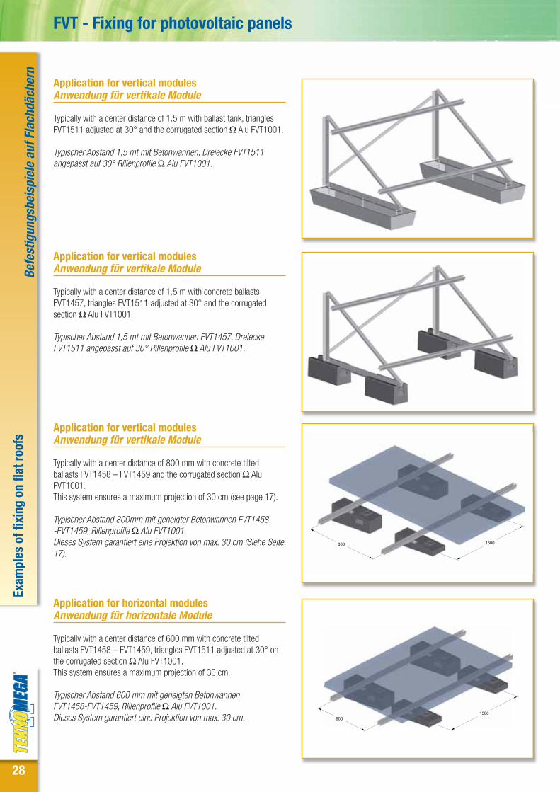
Application for vertical modulesAnwendung für vertikale Module
Typically with a center distance of 1.5 m with ballast tank, trianglesFVT1511 adjusted at 30° and the corrugated section Ω Alu FVT1001.
Typischer Abstand 1,5 mt mit Betonwannen, Dreiecke FVT1511angepasst auf 30° Rillenprofile Ω Alu FVT1001.
Application for vertical modulesAnwendung für vertikale Module
Typically with a center distance of 1.5 m with concrete ballastsFVT1457, triangles FVT1511 adjusted at 30° and the corrugatedsection Ω Alu FVT1001.
Typischer Abstand 1,5 mt mit Betonwannen FVT1457, DreieckeFVT1511 angepasst auf 30° Rillenprofile Ω Alu FVT1001.
800 1500
Application for vertical modulesAnwendung für vertikale Module
Typically with a center distance of 800 mm with concrete tiltedballasts FVT1458 – FVT1459 and the corrugated section Ω AluFVT1001.This system ensures a maximum projection of 30 cm (see page 17).
Typischer Abstand 800mm mit geneigter Betonwannen FVT1458-FVT1459, Rillenprofile Ω Alu FVT1001.Dieses System garantiert eine Projektion von max. 30 cm (Siehe Seite.17).
6001500
Application for horizontal modules Anwendung für horizontale Module
Typically with a center distance of 600 mm with concrete tiltedballasts FVT1458 – FVT1459, triangles FVT1511 adjusted at 30° onthe corrugated section Ω Alu FVT1001.This system ensures a maximum projection of 30 cm.
Typischer Abstand 600 mm mit geneigten BetonwannenFVT1458-FVT1459, Rillenprofile Ω Alu FVT1001.Dieses System garantiert eine Projektion von max. 30 cm.

29
FVT - Befestigungssysteme für Photovoltaik-Module
New application for vertical modulessAnwendung für vertikale Module
Typically with a center distance of 1.5 m with rail FVT1002ballasted with FVT1465, triangles FVT1511 adjusted at 30°and corrugated section Ω Alu FVT1001.
Typischer Abstand 1,5 mt mit Schiene FVT1002, gewichtetmit FVT1465, Dreiecke FVT1511 angepasst auf 30°undRillenprofile Ω Alu FVT1001.
DET. BDET. A DET. C
A BC
Installation of the jaws Montageanleitung der Spannbacken
Ω-shaped intermediate and Z lateral jaws installation onALUMINIUM section or hot galvanizes steel. The assembly canbe carried out with TCEI screw with washer and rectangularnut with spring or by using the pre-assembled kits.
Montage der „Ω- förmigen Zwischenspannbacken” und der“Z-förmigen seitlichen” Spannbacken auf dieAluminiumprofile oder Profile aus feuerverzinktem Stahl. DieMontage kann mit TCEI- Schrauben mit Unterlegscheibe undrechteckiger Mutter ausgeführt werden oder unterVerwendung des vormontierten Kits.
Exam
ples
of f
ixin
g on
flat
roof
sBe
fest
igun
gsbe
ispi
ele
auf F
lach
däch
ern
FVT4031
60
A
FVT4114
24
23
60

30
Exam
ples
of f
ixin
g on
slo
ping
roof
sBe
fest
igun
gsbe
ispi
ele
auf S
pitz
däch
ern
FVT - Fixing for photovoltaic panels
FVT1120 FVT1240 FVT1246 FVT1260
FVT1250 FVT1256 FVT1180 FVT1267
Range of the brackets for sloping roofs - Sortiment von Halterungen auf SpitzdächernTo be fixed on concrete - Für die Halterung auf Beton
To be fixed on wood - Für die Halterung auf Holz
FVT

31
Phot
os o
f the
app
licat
ions
Foto
s vo
n An
wen
dung
en
FVT - Befestigungssysteme für Photovoltaik-Module
Sloping roof- asbestos recovery. Application with mill screws for woodFVT1315Spitzdach. Anwendung mit Holzschrauben FVT1315
Metal decking roof. Application with brackets as per drawingFVT95XXWellblechdach. Anwendung mit Halterungen nach Maß FVT95XX
Flat industrial roof with gravel. Application with ballast tanks FVT1455and triangles at 30° FVT1511Industrie-Flachdach mit Kies. Anwendung mit BetonwannenFVT1455 und 30°- Dreiecke FVT1511
Sloping roof with tiles. Application with stainless steel adjustablebracket FVT1256.Spitzdach mit Ziegeln. Anwendung mit verstellbaren Edelstahl-Halterungen FVT1256
Industrial sheath arched roof. Direct application of the hot galvanizedPRF with Butyl gasket.Gewölbeartige Industrie-Dachschalung. Direkte Anwendung PRFfeuerverzinkt mit Butyl- Dichtung
Flat industrial roof with sheath. Application with ballast tanksFVT1455 and triangles at 30° FVT1511.Industrie-Flachdach. Anwendung mit BetonwannenFVT1455 und 30°- Dreiecke FVT1511

32
FVT - Fixing for photovoltaic panels
Material: Galvanized FeP02 Steel UNI EN 10111-2008Material: Feuerverzinkter Stahl FeP02 UNI EN UNI EN 10111-2008
78,5
210000
79000
1,2*10-5
-
430
190
KN/m3
N/mm2
N/mm2
1/°C
N/mm2
N/mm2
N/mm2
PROFILE 41x21x2.5 mm – Slotted on the bottomPROFIL 41x21x2,5 mm - An der Unterseite geschlitzt
Mechanical features - Mechanische Eigenschaften204,1
1,6
10727
52963
928
2584
7,3
16,1
A
pp
Jx
Jy
Wx
Wy
ix
iy
Section area - Schnittfläche
Linear meter weight - Laufmetergewicht
Moment of inertia X - Trägheitsmoment X
Moment of inertia Y - Trägheitsmoment Y
Resistant moment X - Schnittfläche
Resistant moment Y - Widerstandsmoment X
Inertia ray X - Trägheitsradius X
Inertia ray Y - Trägheitsradius Y
mm2
daN/m
mm4
mm4
mm3
mm3
mm
mm
PROFILE 41x41x2.5 mm – Slotted on three sidesPROFIL 41x41x2,5 mm - An drei Seiten geschlitzt
Mechanical features - Mechanische Eigenschaften249,1
1,96
61156
69661
2799
3398
15,7
16,7
A
pp
Jx
Jy
Wx
Wy
ix
iy
Section area - Schnittfläche
Linear meter weight - Laufmetergewicht
Moment of inertia X - Trägheitsmoment X
Moment of inertia Y - Trägheitsmoment Y
Resistant moment X - Schnittfläche
Resistant moment Y - Widerstandsmoment X
Inertia ray X - Trägheitsradius X
Inertia ray Y - Trägheitsradius Y
mm2
daN/m
mm4
mm4
mm3
mm3
mm
mm
Table of the allowable loads (with Fmax <L/250)Tabelle mit den zulässigen Belastungen (mit Fmax < L/250)
Beam length L (mm)Leitungslänge L (mm)
Uniform load distribution (daN/m)Belastung einheitl. Verteilung (daN/m)
Load at the centerline (daN)In der Mitte konzentrierte Belastung (daN)
554
164
69
35
20
13
9
500
750
1000
1250
1500
1750
2000
141
77
43
28
19
14
11
Table of the allowable loads (with Fmax <L/250)Tabelle mit den zulässigen Belastungen (mit Fmax < L/250)
Beam length L (mm)Leitungslänge L (mm)
Uniform load distribution (daN/m)Belastung einheitl. Verteilung (daN/m)
Load at the centerline (daN)In der Mitte konzentrierte Belastung (daN)
1702
756
395
202
117
74
49
500
750
1000
1250
1500
1750
2000
425
284
213
158
110
81
62
HOT GALVANIZES STEEL PROFILES - FEUERVERZINKTE PROFILE AUS STAHL
X
Y
9.44
X
Y
19.1
5
Specific weight - Spezifisches Gewicht
Longitudinal elasticity module - Longitudinale Elastizitätsmodul
Tangential elasticity module - Tangentiales Elastizitätsmodul
Linear thermal dilatation coefficient - Linearer Wärmeausdehnungskoeffizient
Resistance to the last limit fy - Widerstand gegen die ultimative Grenze fy
Resistance to the yield strength limit fy- Widerstand gegen die Streckgrenze fy
Resistance to the yield limit f0,2 - Widerstand gegen die Dehnungsgrenze f0,2
Ω S
TRUT
- St
eel p
rofil
es –
Tabl
es o
f pro
file
load
sΩ
STR
UT -
Prof
ile a
us S
tahl
- Ta
belle
Bela
stun
gen
der P
rofil
e

33
FVT - Befestigungssysteme für Photovoltaik-Module
Material: Stainless AISI304 Steel UNI EN 10088-3 2005Material : Edelstahl AISI 304 n. 1.4301 EN 10088-3 2005
79,1
196000
86000
1,65*10-5
500
-
190
Specific weight - Spezifisches Gewicht
Longitudinal elasticity module - Longitudinale Elastizitätsmodul
Tangential elasticity module - Tangentiales Elastizitätsmodul
Linear thermal dilatation coefficient - Linearer Wärmeausdehnungskoeffizient
Resistance to the last limit fy - Widerstand gegen die ultimative Grenze fy
Resistance to the yield strength limit fy- Widerstand gegen die Streckgrenze fy
Resistance to the yield limit f0,2 - Widerstand gegen die Dehnungsgrenze f0,2
KN/m3
N/mm2
N/mm2
1/°C
N/mm2
N/mm2
N/mm2
PROFILE 41x21x1.5 mm – Slotted on the bottomPROFIL 41x21x1,5 mm - An der Unterseite geschlitzt
Mechanical features - Mechanische Eigenschaften130,8
1,03
7585
35131
658
1714
7,6
16,4
A
pp
Jx
Jy
Wx
Wy
ix
iy
Section area - Schnittfläche
Linear meter weight - Laufmetergewicht
Moment of inertia X - Trägheitsmoment X
Moment of inertia Y - Trägheitsmoment Y
Resistant moment X - Schnittfläche
Resistant moment Y - Widerstandsmoment X
Inertia ray X - Trägheitsradius X
Inertia ray Y - Trägheitsradius Y
mm2
daN/m
mm4
mm4
mm3
mm3
mm
mm
PROFILE 41x41x1.5 mm – Slotted on the bottomPROFIL 41x41x1,5 mm - An der Unterseite geschlitzt
Mechanical features - Mechanische Eigenschaften157,8
1,25
40701
45668
1864
2228
16,1
17,0
A
pp
Jx
Jy
Wx
Wy
ix
iy
Section area - Schnittfläche
Linear meter weight - Laufmetergewicht
Moment of inertia X - Trägheitsmoment X
Moment of inertia Y - Trägheitsmoment Y
Resistant moment X - Schnittfläche
Resistant moment Y - Widerstandsmoment X
Inertia ray X - Trägheitsradius X
Inertia ray Y - Trägheitsradius Y
mm2
daN/m
mm4
mm4
mm3
mm3
mm
mm
Table of the allowable loads (with Fmax <L/250)Tabelle mit den zulässigen Belastungen (mit Fmax < L/250 )
Beam length L (mm)Leitungslänge L (mm)
Uniform load distribution (daN/m)Belastung einheitl. Verteilung (daN/m)
Load at the centerline (daN)In der Mitte konzentrierte Belastung (daN)
365
108
46
23
14
9
6
500
750
1000
1250
1500
1750
2000
100
51
29
18
13
9
7
Table of the allowable loads (with Fmax <L/250)Tabelle mit den zulässigen Belastungen (mit Fmax < L/250)
Beam length L (mm)Leitungslänge L (mm)
Uniform load distribution (daN/m)Belastung einheitl. Verteilung (daN/m)
Load at the centerline (daN)In der Mitte konzentrierte Belastung (daN)
1134
504
245
125
73
46
31
500
750
1000
1250
1500
1750
2000
283
189
142
98
68
50
38
STAINLESS STEEL PROFILES - EDELSTAHL- PROFILE
X
Y
9.47
X
Y
19.1
7
Ω S
TRUT
- St
ainl
ess s
teel
pro
files
- Ta
bles
of p
rofil
e lo
ads
Ω S
TRUT
- Pr
ofile
aus
Sta
hl -
Tabe
lle B
elast
unge
n de
r Pro
file
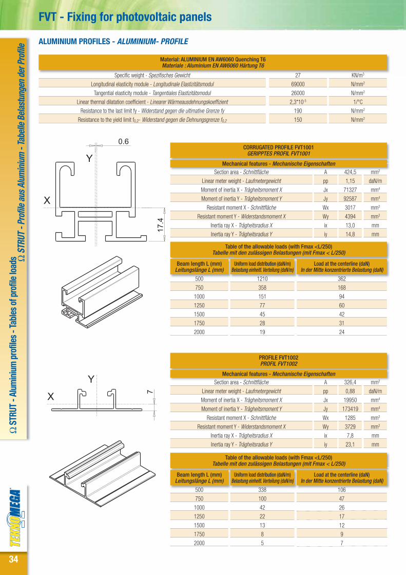
34
Material: ALUMINIUM EN AW6060 Quenching T6Materiale : Aluminium EN AW6060 Härtung T6
27
69000
26000
2,3*10-5
190
150
Specific weight - Spezifisches Gewicht
Longitudinal elasticity module - Longitudinale Elastizitätsmodul
Tangential elasticity module - Tangentiales Elastizitätsmodul
Linear thermal dilatation coefficient - Linearer Wärmeausdehnungskoeffizient
Resistance to the last limit fy - Widerstand gegen die ultimative Grenze fy
Resistance to the yield limit f0,2- Widerstand gegen die Dehnungsgrenze f0,2
KN/m3
N/mm2
N/mm2
1/°C
N/mm2
N/mm2
CORRUGATED PROFILE FVT1001GERIPPTES PROFIL FVT1001
Mechanical features - Mechanische Eigenschaften424,5
1,15
71327
92587
3017
4394
13,0
14,8
A
pp
Jx
Jy
Wx
Wy
ix
iy
Section area - Schnittfläche
Linear meter weight - Laufmetergewicht
Moment of inertia X - Trägheitsmoment X
Moment of inertia Y - Trägheitsmoment Y
Resistant moment X - Schnittfläche
Resistant moment Y - Widerstandsmoment X
Inertia ray X - Trägheitsradius X
Inertia ray Y - Trägheitsradius Y
mm2
daN/m
mm4
mm4
mm3
mm3
mm
mm
PROFILE FVT1002 PROFIL FVT1002
Mechanical features - Mechanische Eigenschaften326,4
0,88
19950
173419
1285
3729
7,8
23,1
A
pp
Jx
Jy
Wx
Wy
ix
iy
Section area - Schnittfläche
Linear meter weight - Laufmetergewicht
Moment of inertia X - Trägheitsmoment X
Moment of inertia Y - Trägheitsmoment Y
Resistant moment X - Schnittfläche
Resistant moment Y - Widerstandsmoment X
Inertia ray X - Trägheitsradius X
Inertia ray Y - Trägheitsradius Y
mm2
daN/m
mm4
mm4
mm3
mm3
mm
mm
Table of the allowable loads (with Fmax <L/250)Tabelle mit den zulässigen Belastungen (mit Fmax < L/250)
Beam length L (mm)Leitungslänge L (mm)
Uniform load distribution (daN/m)Belastung einheitl. Verteilung (daN/m)
Load at the centerline (daN)In der Mitte konzentrierte Belastung (daN)
1210
358
151
77
45
28
19
500
750
1000
1250
1500
1750
2000
362
168
94
60
42
31
24
Table of the allowable loads (with Fmax <L/250)Tabelle mit den zulässigen Belastungen (mit Fmax < L/250)
Beam length L (mm)Leitungslänge L (mm)
Uniform load distribution (daN/m)Belastung einheitl. Verteilung (daN/m)
Load at the centerline (daN)In der Mitte konzentrierte Belastung (daN)
338
100
42
22
13
8
5
500
750
1000
1250
1500
1750
2000
106
47
26
17
12
9
7
ALUMINIUM PROFILES - ALUMINIUM- PROFILE
X
Y
0.6
17.4
X
Y
7
FVT - Fixing for photovoltaic panelsΩ
STR
UT -
Alum
iniu
m p
rofil
es -
Tabl
es o
f pro
file
load
s Ω S
TRUT
- Pr
ofile
aus
Alu
min
ium
- Ta
belle
Bela
stun
gen
der P
rofil
e

35
Material: Aluminium EN AW6060 Quenching T6Material: Aluminium EN AW6060 Härtung T6
27
69000
26000
2,3*10-5
190
150
Specific weight - Spezifisches Gewicht
Longitudinal elasticity module - Longitudinale Elastizitätsmodul
Tangential elasticity module - Tangentiales Elastizitätsmodul
Linear thermal dilatation coefficient - Linearer Wärmeausdehnungskoeffizient
Resistance to the last limit fy - Widerstand gegen die ultimative Grenze fy
Resistance to the yield limit f0,2- Widerstand gegen die Dehnungsgrenze f0,2
KN/m3
N/mm2
N/mm2
1/°C
N/mm2
N/mm2
SIMPLE PROFILE FVT1000 Th. 2.3 mmEINFACHES PROFIL FVT1000 Sp. 2,3 mm
Mechanical features - Mechanische Eigenschaften400,3
1,08
77497
97445
3288
4753
13,9
15,6
A
pp
Jx
Jy
Wx
Wy
ix
iy
Section area - Schnittfläche
Linear meter weight - Laufmetergewicht
Moment of inertia X - Trägheitsmoment X
Moment of inertia Y - Trägheitsmoment Y
Resistant moment X - Schnittfläche
Resistant moment Y - Widerstandsmoment X
Inertia ray X - Trägheitsradius X
Inertia ray Y - Trägheitsradius Y
mm2
daN/m
mm4
mm4
mm3
mm3
mm
mm
SIMPLE PROFILE FVT1010 Th. 1.6 mmEINFACHES PROFIL FVT1010 Sp. 1,6 mm
Mechanical features - Mechanische Eigenschaften293,4
0,79
60429
71873
2542
3506
14,4
15,7
A
pp
Jx
Jy
Wx
Wy
ix
iy
Section area - Schnittfläche
Linear meter weight - Laufmetergewicht
Moment of inertia X - Trägheitsmoment X
Moment of inertia Y - Trägheitsmoment Y
Resistant moment X - Schnittfläche
Resistant moment Y - Widerstandsmoment X
Inertia ray X - Trägheitsradius X
Inertia ray Y - Trägheitsradius Y
mm2
daN/m
mm4
mm4
mm3
mm3
mm
mm
Table of the allowable loads (with Fmax <L/250)Tabelle mit den zulässigen Belastungen (mit Fmax < L/250)
Beam length L (mm)Leitungslänge L (mm)
Uniform load distribution (daN/m)Belastung einheitl. Verteilung (daN/m)
Load at the centerline (daN)In der Mitte konzentrierte Belastung (daN)
1314
389
164
84
49
31
21
500
750
1000
1250
1500
1750
2000
395
183
103
66
46
34
26
Table of the allowable loads (with Fmax <L/250)Tabelle mit den zulässigen Belastungen (mit Fmax < L/250)
Beam length L (mm)Leitungslänge L (mm)
Uniform load distribution (daN/m)Belastung einheitl. Verteilung (daN/m)
Load at the centerline (daN)In der Mitte konzentrierte Belastung (daN)
1025
304
128
66
38
24
16
500
750
1000
1250
1500
1750
2000
305
142
80
51
36
26
20
ALUMINIUM PROFILES - ALUMINIUM- PROFILE
X
Y
17.4
X
Y
17.2
FVT - Befestigungssysteme für Photovoltaik-Module
Ω S
TRUT
- Al
umin
ium
pro
files
- Ta
bles
of p
rofil
e lo
ads Ω
STR
UT -
Prof
ile a
us A
lum
iniu
m -
Tabe
lle B
elast
unge
n de
r Pro
file

3636
List
of a
lpha
num
eric
par
tnum
bers
Verz
eich
nis
der a
lpha
num
eris
chen
Cod
enum
mer
nFVT - Fixing for photovoltaic panels - Befestigungssysteme für Photovoltaik-Module
Code - Code Reference - Referenz Page - Seite Code - Code Reference - Referenz Page - Seite Code - Code Reference - Referenz Page - Seite
BULBUL1020 BUL-TP21 21
BUL1025 BUL-TP41 21
DAPDAP2000 DAP-M6-S-ZC 19
DAP2005 DAP-M8-S-ZC 19
DAP2010 DAP-M10-S-ZC 19
DAP2020 DAP-M6-C-ZC 19
DAP2025 FVA-M8-C-ZC 19
DAP2030 FVA-M10-C-ZC 19
DAP2040 FVA-M6-L-ZC 19
DAP2045 FVA-M8-L-ZC 19
DAP2050 FVA-M10-L-ZC 19
DAP3005 FVA-M8-S-SS 19
DAP3010 FVA-M10-S-SS 19
DAP3025 FVA-M8-C-SS 19
DAP3030 FVA-M10-C-SS 19
DAP3045 FVA-M8-L-SS 19
DAP3050 FVA-M10-L-SS 19
FVTFVT1000 FVP-L3.1-S-ALU 6
FVT1001 FVP-L3.1-PC-ALU 6
FVT1002 FVP-L3.1- K-ALU 6
FVT1005 FVP-L6.2-S-ALU 6
FVT1006 FVP-L6.2-PC-ALU 6
FVT1007 FVP-L6.2- K-ALU 6
FVT1010 FVP-L3.1-SL-ALU 6
FVT1015 FVP-L6.2-SL-ALU 6
FVT1040 FVS-Z33-INOX 8
FVT1045 FVS-Z34-INOX 8
FVT1050 FVS-Z35-INOX 8
FVT1055 FVS-Z37-INOX 8
FVT1060 FVS-Z39-INOX 8
FVT1065 FVS-Z41-INOX 8
FVT1066 FVS-Z43-INOX 8
FVT1070 FVS-Z45-INOX 8
FVT1075 FVS-Z47-INOX 8
FVT1080 FVS-Z49-INOX 8
FVT1111 FVS- -U-EVO 9
FVT1113 FVT-FPP-INOX 9
FVT1115 FVS-PU-INOX 6
FVT1120 FVS-S-105-ZC 10
FVT1125 FVS-S-110-ZC 10
FVT1130 FVS-S-115-ZC 10
FVT1135 FVS-S-120-ZC 10
FVT1140 FVS-S-125-ZC 10
FVT1145 FVS-S-130-ZC 10
FVT1180 FVS-P-105-ZC 10
FVT1185 FVS-P-110-ZC 10
FVT1190 FVS-P-115-ZC 10
FVT1195 FVS-P-120-ZC 10
FVT1200 FVS-P-125-ZC 10
FVT1205 FVS-P-130-ZC 10
FVT1240 FVS-S-RGL-ZC 10
FVT1246 FVS-S-RGL-EVO 10
FVT1250 FVS-P-RGL-ZC 11
FVT1256 FVS-P-RGL-EVO 11
FVT1260 FVS-C-RGL-ZC 11
FVT1265 FVS-C-RGL-INOX 11
FVT1267 FVS-R-RGL-INOX 11
FVT1270 FVS-AV-ZC 18
FVT1285 FVT-SCV-ZC 17
FVT1286 FVT-SCV-ALU 17FVT1287 FVT-SCV-S-ALU 17FVT1299 FVT-SLG-MRS-INOX 12FVT1300 FVA-AF-10X200-INOX 14FVT1305 FVA-AF-10X250-INOX 14FVT1310 FVA-AF-12X250-INOX 14FVT1315 FVA-AF-12X300-INOX 14FVT1316 FVA-AF-12X350-INOX 14FVT1317 FVA-AF-80-50M10-INOX 14FVT1318 FVA-AF-100-50M10-INOX 14FVT1319 FVA-AF-150-50M10-INOX 14FVT1320 FVA-TE-8x16-INOX 19FVT1325 FVA-TE-10x20-INOX 19FVT1330 FVA-TCEI-8x10-INOX 19FVT1332 FVA-TCEI-8x20-INOX 19FVT1335 FVA-TCEI-8x25-INOX 19FVT1337 FVA-TCEI-8x30-INOX 19FVT1340 FVA-TCEI-8x40-INOX 19FVT1342 FVA-TCEI-8x50-INOX 19FVT1344 FVA-TCEI-8x70-INOX 19FVT1345 FVA-TCEI-10x25-INOX 19FVT1346 FVA-TCEI-10x20-INOX 19FVT1350 FVA-TCEI-10x40-INOX 19FVT1355 FVA-TCEI-10x50-INOX 19FVT1356 FVA-SA-8-INOX 20FVT1359 FVA-DR-M10-INOX 20FVT1360 FVA- B-8x10-INOX 20FVT1365 FVA- B-8x25-INOX 20FVT1370 FVA- B-8x30-INOX 20FVT1375 FVA- B-8x35-INOX 20FVT1380 FVA- B-8x40-INOX 20FVT1385 FVA- B-8x45-INOX 20FVT1390 FVA- B-8x50-INOX 20FVT1391 FVA- B-Key 20FVT1395 FVA-TM-8X30-ZC 19FVT1400 FVA-TM-10X30-ZC 19FVT1405 FVA-BF-M8-INOX 20FVT1410 FVA-BF-M10-INOX 20FVT1415 FVA-MF-8x30-INOX 20FVT1420 FVA-MF-10x30-INOX 20FVT1455 FVV-VSC-SDZ 17FVT1456 FVV-VSC-SDZ-OR 17FVT1457 FVV-ZVC 17FVT1458 FVV-ZVC-30-1 17FVT1459 FVV-ZVC-30-2 17FVT1465 FVV-ZVC-1002 17FVT1470 RIV-ST-48-11-ALU 20FVT1511 FVT-TRG-R-EVO 15FVT1512 FVT-TRG-OR 15FVT1513 FVT-TRG-RR 16FVT1514 FVT-TRG-DP-V 16FVT1515 FVT-P2-SS 14FVT1517 FVT-TRG-DP-O 16FVT1530 FVT-GN-120 21FVT1535 FVT-GN-80 21FVT1540 FVT-GN-7 21FVT1545 FVT-VLG 5,5X25-INOX 12FVT1550 FVT-GBU-50 21FVT1551 FVT-GBU-10 21FVT1552 FVT-GBU-120 21FVT1555 FVT-MBI-1000 21FVT1560 FVT-MBI-K 21FVT2511 FVT-TRG-RB-MV 15
FVT2512 FVT-TRG-RB-MO 15
FVT3031 FVS-Z-31-ALU 8
FVT3034 FVS-Z-34-ALU 8
FVT3036 FVS-Z-36-ALU 8
FVT3039 FVS-Z-39-ALU 8
FVT3041 FVS-Z-41-ALU 8
FVT3044 FVS-Z-44-ALU 8
FVT3046 FVS-Z-46-ALU 8
FVT3049 FVS-Z-49-ALU 8
FVT3051 FVS-Z-51-ALU 8
FVT3112 FVS- -U-ALU 9
FVT4031 FVS-ZP-31-ALU 8
FVT4034 FVS-ZP-34-ALU 8
FVT4036 FVS-ZP-36-ALU 8
FVT4039 FVS-ZP-39-ALU 8
FVT4041 FVS-ZP-41-ALU 8
FVT4044 FVS-ZP-44-ALU 8
FVT4046 FVS-ZP-46-ALU 8
FVT4049 FVS-ZP-49-ALU 8
FVT4051 FVS-ZP-51-ALU 8
FVT4114 FVS- -UP-ALU-29-35 9
FVT4115 FVS- -UP-ALU-36-45 9
FVT4116 FVS- -UP-ALU-46-51 9
FVT5000 FVT-SLG-UO80-INOX 13
FVT5005 FVT-SLG-UV280-INOX 13
FVT5010 FVT-SLG-UV400-INOX 13
FVT5030 FVS-UP-30-INOX 13
FVT5033 FVS-UP-33-INOX 13
FVT5036 FVS-UP-36-INOX 13
FVT5038 FVS-UP-38-INOX 13
FVT5041 FVS-UP-41-INOX 13
FVT5043 FVS-UP-43-INOX 13
FVT5046 FVS-UP-46-INOX 13
FVT5048 FVS-UP-48-INOX 13
FVT5051 FVS-UP-51-INOX 13
FVT50XX Dima di Fissaggio 13
FVT95XX FVT-SLG-R 12
FVT96XX FVT-SLG-P 12
PRFPRF1145 PRF-B3-ZF 7
PRF1150 PRF-B4-ZF 7
PRF1155 PRF-B6-ZF 7
PRF1225 PRF-A3-ZF3 7
PRF1230 PRF-A4-ZF3 7
PRF1235 PRF-A6-ZF3 7
PRF9000 PRF-A3-SSF 7
PRF9004 PRF-B3-SSF 7
STFSTF1012 STF-GI-PB-Inox 7
STF1013 STF-GI-PA-Inox 7
STF1025 STF-041 18
STF1030 STF-021 18
STF1035 STF-82 18
STF1050 STF-B41 18
STF1100 STF-W45 18
STF1101 STF-W30A 18
STF1102 STF-W30-90A 18
STF1105 STF-WL2 18
STF1110 STF-WL3 18
STF1115 STF-WL4 18
STF1120 STF-WL4R 18
STF1140 STF-SR300 18

Page-Seite 6 Page-Seite 6 Page-Seite 7 Page-Seite 6-7
Page-Seite 8-9 Page-Seite 10-11 Page-Seite 10 Page-Seite 11
Page-Seite 12 Page-Seite 13 Page-Seite 14
Page-Seite 15 Page-Seite 15 Page-Seite 17 Page-Seite 17
Page-Seite 17 Page-Seite 18 Page-Seite 19-20 Page-Seite 21
Page-Seite 13
Example of a certification for a project Beispiel für die Zertifizierung eines Projekts

Product cataloguesProduktkatalog
Fixing systems for photovoltaic panelsBefestigungssysteme für Photovoltaik-Module
FVT
6/11
EN/
DETeknomega s.r.l.via E. Fermi, 27 - 20090 Buccinasco (MI)tel. +39.02.45707533 - +39.02.48844281Fax +39.02.45705673e-mail: [email protected]
Teknomega GmbH & Co.KGHauptstr. 76 - 67715 Geiselbergtel. 06307 / 9127-127Fax 06307 / 9127-128e-mail: [email protected]